EP3865688A1 - Diverter fittings for cooling systems of an engine - Google Patents
Diverter fittings for cooling systems of an engine Download PDFInfo
- Publication number
- EP3865688A1 EP3865688A1 EP21153363.3A EP21153363A EP3865688A1 EP 3865688 A1 EP3865688 A1 EP 3865688A1 EP 21153363 A EP21153363 A EP 21153363A EP 3865688 A1 EP3865688 A1 EP 3865688A1
- Authority
- EP
- European Patent Office
- Prior art keywords
- cavity
- opening
- coolant
- engine block
- diverter fitting
- Prior art date
- Legal status (The legal status is an assumption and is not a legal conclusion. Google has not performed a legal analysis and makes no representation as to the accuracy of the status listed.)
- Granted
Links
Images



Classifications
-
- F—MECHANICAL ENGINEERING; LIGHTING; HEATING; WEAPONS; BLASTING
- F01—MACHINES OR ENGINES IN GENERAL; ENGINE PLANTS IN GENERAL; STEAM ENGINES
- F01P—COOLING OF MACHINES OR ENGINES IN GENERAL; COOLING OF INTERNAL-COMBUSTION ENGINES
- F01P7/00—Controlling of coolant flow
- F01P7/14—Controlling of coolant flow the coolant being liquid
- F01P7/16—Controlling of coolant flow the coolant being liquid by thermostatic control
-
- F—MECHANICAL ENGINEERING; LIGHTING; HEATING; WEAPONS; BLASTING
- F01—MACHINES OR ENGINES IN GENERAL; ENGINE PLANTS IN GENERAL; STEAM ENGINES
- F01P—COOLING OF MACHINES OR ENGINES IN GENERAL; COOLING OF INTERNAL-COMBUSTION ENGINES
- F01P3/00—Liquid cooling
- F01P3/12—Arrangements for cooling other engine or machine parts
-
- F—MECHANICAL ENGINEERING; LIGHTING; HEATING; WEAPONS; BLASTING
- F01—MACHINES OR ENGINES IN GENERAL; ENGINE PLANTS IN GENERAL; STEAM ENGINES
- F01P—COOLING OF MACHINES OR ENGINES IN GENERAL; COOLING OF INTERNAL-COMBUSTION ENGINES
- F01P7/00—Controlling of coolant flow
- F01P7/14—Controlling of coolant flow the coolant being liquid
-
- F—MECHANICAL ENGINEERING; LIGHTING; HEATING; WEAPONS; BLASTING
- F01—MACHINES OR ENGINES IN GENERAL; ENGINE PLANTS IN GENERAL; STEAM ENGINES
- F01P—COOLING OF MACHINES OR ENGINES IN GENERAL; COOLING OF INTERNAL-COMBUSTION ENGINES
- F01P3/00—Liquid cooling
- F01P3/02—Arrangements for cooling cylinders or cylinder heads
-
- F—MECHANICAL ENGINEERING; LIGHTING; HEATING; WEAPONS; BLASTING
- F01—MACHINES OR ENGINES IN GENERAL; ENGINE PLANTS IN GENERAL; STEAM ENGINES
- F01P—COOLING OF MACHINES OR ENGINES IN GENERAL; COOLING OF INTERNAL-COMBUSTION ENGINES
- F01P3/00—Liquid cooling
- F01P3/20—Cooling circuits not specific to a single part of engine or machine
-
- F—MECHANICAL ENGINEERING; LIGHTING; HEATING; WEAPONS; BLASTING
- F01—MACHINES OR ENGINES IN GENERAL; ENGINE PLANTS IN GENERAL; STEAM ENGINES
- F01P—COOLING OF MACHINES OR ENGINES IN GENERAL; COOLING OF INTERNAL-COMBUSTION ENGINES
- F01P5/00—Pumping cooling-air or liquid coolants
- F01P5/10—Pumping liquid coolant; Arrangements of coolant pumps
-
- F—MECHANICAL ENGINEERING; LIGHTING; HEATING; WEAPONS; BLASTING
- F01—MACHINES OR ENGINES IN GENERAL; ENGINE PLANTS IN GENERAL; STEAM ENGINES
- F01M—LUBRICATING OF MACHINES OR ENGINES IN GENERAL; LUBRICATING INTERNAL COMBUSTION ENGINES; CRANKCASE VENTILATING
- F01M5/00—Heating, cooling, or controlling temperature of lubricant; Lubrication means facilitating engine starting
- F01M5/002—Cooling
- F01M2005/004—Oil-cooled engines
-
- F—MECHANICAL ENGINEERING; LIGHTING; HEATING; WEAPONS; BLASTING
- F01—MACHINES OR ENGINES IN GENERAL; ENGINE PLANTS IN GENERAL; STEAM ENGINES
- F01P—COOLING OF MACHINES OR ENGINES IN GENERAL; COOLING OF INTERNAL-COMBUSTION ENGINES
- F01P3/00—Liquid cooling
- F01P3/02—Arrangements for cooling cylinders or cylinder heads
- F01P2003/021—Cooling cylinders
-
- F—MECHANICAL ENGINEERING; LIGHTING; HEATING; WEAPONS; BLASTING
- F01—MACHINES OR ENGINES IN GENERAL; ENGINE PLANTS IN GENERAL; STEAM ENGINES
- F01P—COOLING OF MACHINES OR ENGINES IN GENERAL; COOLING OF INTERNAL-COMBUSTION ENGINES
- F01P7/00—Controlling of coolant flow
- F01P7/14—Controlling of coolant flow the coolant being liquid
- F01P2007/143—Controlling of coolant flow the coolant being liquid using restrictions
-
- F—MECHANICAL ENGINEERING; LIGHTING; HEATING; WEAPONS; BLASTING
- F01—MACHINES OR ENGINES IN GENERAL; ENGINE PLANTS IN GENERAL; STEAM ENGINES
- F01P—COOLING OF MACHINES OR ENGINES IN GENERAL; COOLING OF INTERNAL-COMBUSTION ENGINES
- F01P7/00—Controlling of coolant flow
- F01P7/14—Controlling of coolant flow the coolant being liquid
- F01P2007/146—Controlling of coolant flow the coolant being liquid using valves
-
- F—MECHANICAL ENGINEERING; LIGHTING; HEATING; WEAPONS; BLASTING
- F01—MACHINES OR ENGINES IN GENERAL; ENGINE PLANTS IN GENERAL; STEAM ENGINES
- F01P—COOLING OF MACHINES OR ENGINES IN GENERAL; COOLING OF INTERNAL-COMBUSTION ENGINES
- F01P2031/00—Fail safe
- F01P2031/32—Deblocking of damaged thermostat
-
- F—MECHANICAL ENGINEERING; LIGHTING; HEATING; WEAPONS; BLASTING
- F01—MACHINES OR ENGINES IN GENERAL; ENGINE PLANTS IN GENERAL; STEAM ENGINES
- F01P—COOLING OF MACHINES OR ENGINES IN GENERAL; COOLING OF INTERNAL-COMBUSTION ENGINES
- F01P2060/00—Cooling circuits using auxiliaries
- F01P2060/04—Lubricant cooler
-
- F—MECHANICAL ENGINEERING; LIGHTING; HEATING; WEAPONS; BLASTING
- F01—MACHINES OR ENGINES IN GENERAL; ENGINE PLANTS IN GENERAL; STEAM ENGINES
- F01P—COOLING OF MACHINES OR ENGINES IN GENERAL; COOLING OF INTERNAL-COMBUSTION ENGINES
- F01P2060/00—Cooling circuits using auxiliaries
- F01P2060/04—Lubricant cooler
- F01P2060/045—Lubricant cooler for transmissions
-
- F—MECHANICAL ENGINEERING; LIGHTING; HEATING; WEAPONS; BLASTING
- F01—MACHINES OR ENGINES IN GENERAL; ENGINE PLANTS IN GENERAL; STEAM ENGINES
- F01P—COOLING OF MACHINES OR ENGINES IN GENERAL; COOLING OF INTERNAL-COMBUSTION ENGINES
- F01P2060/00—Cooling circuits using auxiliaries
- F01P2060/06—Retarder
Definitions
- the present disclosure relates generally to a cooling system for an engine, and more particularly relates to a cooling system that utilizes a passive diverter fitting to divert fluid within the cooling system.
- Engines typically include a cooling system that is configured to circulate coolant through the engine block such that the coolant captures the heat from the engine to cool the engine. The coolant then moves through a radiator such that the coolant loses the heat to the atmosphere before moving back through the engine block.
- the engine cooling system can be used to provide auxiliary cooling to coolers for engine accessories (e.g., transmission coolers, brake coolers, etc.).
- engine accessories e.g., transmission coolers, brake coolers, etc.
- conventional transmission coolers and/or brake coolers often use the engine's coolant to cool the hydraulic fluid used with the transmission and/or brake coolers.
- These coolers for engine accessories typically take the form of a shell and tube heat exchanger, which means that these coolers are typically too large to fit on the engine and must be located elsewhere in the machine chassis.
- German Patent No. DE10127711 (“the 711 patent”) discloses a three-way valve that can be used as a replacement to a thermostatic valve in a cooling system for an engine.
- the three-way valve is used to control the mixing ratio between a supply line to a radiator and a bypass line that bypasses the radiator.
- the three-way valve includes a throttle body that is actively controlled to control the diversion of coolant flow to the radiator and the bypass line.
- An exemplary coolant diverter fitting includes a base defining an interior cavity, an inlet opening extending through the base that is in fluid communication with the interior cavity, an outlet opening that is in fluid communication with the interior cavity, and a bypass opening that is in fluid communication with the interior cavity.
- the base is configured to be removably disposed in a cavity of an engine block.
- the inlet opening is in fluid communication with an area exterior to the engine block when the diverter fitting is disposed in the cavity of the engine block.
- the outlet opening is in fluid communication with the area exterior to the engine block when the diverter fitting is disposed in the cavity of the engine block.
- the bypass opening is in fluid communication with an interior coolant passage of the engine block when the diverter fitting is disposed in the cavity of the engine block.
- An exemplary embodiment of an internal combustion engine includes an engine block defining a block interior coolant passage, a cavity disposed in the engine block, and a diverter fitting disposed in the cavity.
- the cavity includes a receiving opening for receiving coolant, an inner opening that is in fluid communication with the block interior coolant passage, and an outer opening that is in fluid communication with an area exterior to the engine block.
- the diverter fitting includes a base defining an interior cavity, an inlet opening, an outlet opening, and a bypass opening.
- the inlet opening is in fluid communication with the receiving opening of the cavity.
- the outlet opening is in fluid communication with the outer opening of the cavity.
- the bypass opening is in fluid communication with the inner opening of the cavity.
- An exemplary cooling system includes a pump, an engine having an engine block, a diverter fitting, and a radiator.
- the pump is configured to pump coolant through the cooling system.
- the engine block includes a block interior coolant passage, a cavity, and a return opening.
- the cavity is in fluid communication with the block interior coolant passage and an area exterior to the housing, and the return opening is in fluid communication with the block interior coolant passage and the area exterior to the housing.
- the diverter fitting includes a base defining an interior cavity, an inlet opening, an outlet opening, and a bypass opening.
- the inlet opening is in fluid communication with the pump.
- the outlet opening is in fluid communication with the inlet opening
- the bypass opening is in fluid communication with the inlet opening of the diverter fitting and the block interior coolant passage of the engine block.
- the external cooler has an inlet passage in fluid communication with the outlet opening of the diverter fitting and an outlet passage in fluid communication with the return opening of the engine block.
- the radiator is in fluid communication with the engine block and the pump.
- the pump is configured to pump coolant through the diverter fitting such that a first portion of the coolant moves through the outlet opening of the diverter fitting and into the external cooler and a second portion of the coolant moves through the bypass opening of the diverter fitting and into the block interior coolant passage of the engine block.
- the present application discloses diverter fittings used for diverting fluid within a cooling system of an engine. While the diverter fitting described herein is described as being used with an engine, it should be understood that the diverter fitting can be used with any other suitable type of cooling system or any other type of system in which fluid is to be diverted.
- FIG. 1 illustrates an exemplary embodiment of a cooling system 100 for an engine 102 (e.g., an internal combustion engine).
- the cooling system includes a pump 104, a diverter fitting 108, an external cooler 110, and a radiator 114.
- the pump 104 is configured to pump coolant (e.g., water, a mixture that includes water, oil, a mixture that includes oil, or any other suitable type of coolant) through the cooling system 100 to cool down the engine 102, as well as cool down fluid moving through the external cooler 110.
- coolant e.g., water, a mixture that includes water, oil, a mixture that includes oil, or any other suitable type of coolant
- the pump 104 can be, for example, a centrifugal pump, or any other suitable type of pump for an engine.
- the external cooler 110 can be, for example, a transmission cooler, a brake cooler, or any other suitable type of external cooler that receives auxiliary cooling from the cooling system 100 of the engine 102.
- the external cooler 110 can take any suitable form, such as, for example, the form of a 4-port style cooler, a shell and tube style cooler, a bathtub 2-port style cooler, or any other suitable type of cooler.
- the external cooler 110 is connected to an engine block 238 ( FIG. 2 ) of the engine 102 such that the external cooler 110 is in fluid communication with a cavity 242 ( FIG. 2 ) of the engine block 238 and a return opening 244 of the engine block 238.
- the cavity 242 and the return opening 244 are each in fluid communication with both an interior coolant passage 240 ( FIG. 2 ) of the engine block 238 and an exterior 246 ( FIG. 2 ) of the engine block 238.
- the interior coolant passage 240 can be, for example, an entry rail, inlet rail, cylinder head water jacket, or any other coolant passage within the interior of the engine block.
- the diverter fitting 108 includes an inlet opening 224 ( FIG. 2 ), an outlet opening 226 ( FIG. 2 ), and a bypass opening 228 ( FIG. 2 ).
- the inlet opening 224 is configured to be positioned to receive coolant when the diverter fitting 108 is disposed in the cavity 242 of the engine block.
- the inlet opening 224 may be in fluid communication with a coolant passage 248 ( FIG. 2 ) that is positioned on the exterior surface of the engine block 238 and in fluid communication with the pump 104.
- the coolant passage 248 may be disposed in an interior of the engine block 238, and the coolant passage 248 is in fluid communication with the exterior 246 of the engine block.
- the diverter fitting 108 is positioned in the cavity 242 such that the outlet opening 226 is in fluid communication with the exterior 246 of the engine block 238 (and the external cooler 110 when the external cooler 110 is attached to the engine block 238), and such that the bypass opening 228 is in fluid communication with the interior coolant passage 240 of the engine block 238.
- the diverter fitting 108 is a modular component that is able to be inserted into and removed from the engine 102.
- coolant 232 pumped by the pump 104 through the passage 248 moves into the inlet opening 224 of the diverter fitting 108 and is split such that a first portion 234 ( FIG. 2 ) of the coolant 232 moves through the outlet opening 226 and enters the external cooler 110, and a second portion 236 ( FIG. 2 ) of the coolant 232 moves through the bypass opening 228 and enters the interior coolant passage 240 of the engine block 238.
- the first portion 234 of the coolant 232 re-enters the interior coolant passage 240 of the engine block 238 through the return opening 244 after moving through the external cooler 110 such that the first portion 234 and the second portion 236 of the coolant 232 mix in the interior coolant passage 240 of the engine block 238 at a position adjacent to wherein the first portion 234 the interior coolant passage 240 enters the engine block 238.
- the diverter fitting 108 is configured to limit the amount of coolant that moves into the external cooler 110.
- the coolant may move into the radiator 114.
- the coolant entering the radiator 114 may become heated as a result of moving through the external cooler 110 and the engine 102.
- the radiator 114 is configured to cool the coolant by transferring heat from the coolant to the surrounding atmosphere.
- the radiator 114 may take any suitable form, such as, for example any form of a heat exchange that is capable of transferring heat from the coolant to the atmosphere.
- the cooling system 100 includes an oil cooler 106 disposed between the pump 104 and the engine 102.
- the pump 104 may first pump coolant through the oil cooler 106 such that the coolant cools oil that is used for lubricating components of the engine 102.
- the oil cooler 106 may be attached to an exterior of the engine block 238 ( FIG. 2 ) of the engine 102, or the oil cooler 106 may be separated from the engine 102 while remaining in fluid communication with the engine 102.
- the cooling system 100 includes a thermostat housing 112 disposed between and in fluid communication with the engine 102 and the radiator 114. After the coolant moves through the engine 102, the coolant enters the thermostat housing 112.
- the thermostat housing 112 houses a thermostat 130 that is configured to regulate the temperature of the coolant. If the coolant is below a predetermined temperature, the thermostat 130 maintains a normally-closed position such that the coolant moves through a bypass line 118 (rather than moving into the radiator 114) and into the pump 104. If the coolant is above a predetermined temperature, the thermostat 130 moves to an open position such that the coolant moves into the radiator 114.
- the pump 104 pumps a portion of the coolant to an aftercooler 116.
- Coolant moving through the aftercooler 116 cools compressed air leaving a turbocharger compressor (not shown) prior to the air entering the engine 102.
- the coolant moves into the engine 102 after exiting the aftercooler 116 such that the coolant mixes with the coolant that entered the engine through the diverter fitting 108 and the external cooler 110.
- the coolant from the aftercooler 116 moves into the thermostat housing 112 after exiting the aftercooler 116 such that the coolant mixes with the coolant from the engine 102 in the thermostat housing 112.
- the mixed coolant exits the thermostat housing 112 and moves into either the bypass line 118 or the radiator 114 depending on whether the thermostat 130 is in the open or closed position.
- an exemplary embodiment of a passive diverter fitting 108 includes a base 320 defining an interior cavity 322, the inlet opening 224, the outlet opening 226, and the bypass opening 228.
- the base 320 can be made of, for example, iron, plastic, or any other suitable material.
- the diverter fitting 108 is made by a casting process or an injection molding process, including the inlet opening 224, the outlet opening 226, and the bypass opening 228.
- the bypass opening 228 is not made by the same process used to manufacture the other portions of the diverter fitting 108, but the bypass opening 228 is made after the remaining portions of the diverter fitting are manufactured.
- the bypass opening 228 can be made by drilling a hole through the base 320 of the diverter fitting 108.
- the base 320 includes a cylindrical side wall 374, an open first end 370 and a closed second end 372.
- the outlet opening 226 is defined by the open first end 370 of the base 320.
- the cylindrical side wall 374 includes an inner surface 376 and an outer surface 378, in which the inner surface 376 defines the interior cavity 322.
- the inlet opening 224 extends through the cylindrical side wall 374 such that the inlet opening 224 is in fluid communication with the interior cavity 322.
- the inlet opening 224 may be positioned on the base 320 such that an axis extending through the inlet opening 224 is perpendicular to an axis that extends through the outlet opening 226.
- the bypass opening 228 extends through the cylindrical side wall 374 such that the bypass opening 228 is in fluid communication with the interior cavity 322.
- the bypass opening 228 may be positioned on the base 320 such that an axis extending through the inlet opening 228 is perpendicular to an axis that extends through the outlet opening 226.
- the inlet opening 224 is positioned on the base substantially opposite the position of the bypass opening 228 (e.g., between about 150 degrees and about 210 degrees about the cylindrical side wall 374 of the base 320, such as about 180 degrees).
- the base 320 is described as having a cylindrical shape, it should be understood that the base 320 can take any suitable form that is capable of being positioned in the cavity 242 of the engine block.
- the diverter fitting 108 includes a protrusion or rib 380 that extends from the inner surface 376 of the base 320.
- the rib 380 is configured to strengthen the base 320 to prevent failure of the diverter fitting 108.
- coolant entering the interior cavity 322 of the base 320 through the inlet opening 224 may engage the inner surface 376 of the base 320 prior to moving through either the outlet opening 226 or the bypass opening 228, and the pressure exerted on the inner surface 376 by the coolant may cause the diverter fitting 108 to wear over time.
- the rib 380 is configured to provide stiffness to the base 320 to strengthen the base and prevent failure of the diverter fitting 108 due to this wear.
- the rib 380 is positioned on the inner surface 376 substantially opposite to the inlet opening 224 (e.g., between about 150 degrees and about 210 degrees about the cylindrical side wall 374 of the base 320, such as about 180 degrees).
- the rib 380 may, however, be positioned at any location on the base 320 that allows the diverter fitting to strengthen and prevent failure of the diverter fitting.
- the inlet opening 224, the outlet opening 226, and the bypass opening 228 may have any suitable size and shape based on the intended use of the diverter fitting 108. That is, these openings 224, 226, 228 may have any size and shape with any suitable cross-sectional areas that allows for adequate cooling of the external cooler 110.
- the outlet opening 226 and the bypass opening 228 have a circular shape.
- an area defined by the bypass opening 228 is less than an area defined by the outlet opening 226.
- the area defined by the bypass opening 228 may be between about 5% and about 25% of the size of the area defined by the outlet opening 226.
- the diverter fitting 108 is configured to be disposed in a cavity 242 of an engine block 238 such that the diverter fitting 108 is positioned to receive coolant from a pump (e.g., pump 104 shown in FIG. 1 ).
- the engine block 238 includes an oil cooler cavity 450 disposed on its exterior surface, in which the oil cooler cavity 450 is configured to receive an oil cooler (e.g., oil cooler 106 shown in FIG. 1 ).
- the cavity 242 includes a receiving opening 452 that is in fluid communication with the oil cooler cavity 450 such that the oil cooler is in fluid communication with the cavity 242.
- the diverter fitting 108 can be positioned in the cavity 242 such that the inlet opening 224 is in fluid communication with the receiving opening 452 and, consequently, in fluid communication with the oil cooler 106.
- the outlet opening 226 of the diverter fitting 108 is in fluid communication with an outer opening 454 ( FIG. 4 ) of the cavity 242.
- a portion of the coolant e.g., the portion 234 of coolant 232 shown in FIG. 2
- the coolant that is pumped through the inlet opening 224 and into the interior cavity 322 of the diverter fitting 108 moves through the outlet opening 226 of the diverter fitting and through the outer opening 454 of the cavity 242.
- the cavity 242 includes an inner opening 456 that is in fluid communication with the interior coolant passage 240 of the engine block 238.
- the bypass opening 228 is in fluid communication with the inner opening 456 of the cavity 242.
- a portion of the coolant e.g., the portion 236 of coolant 232 shown in FIG. 2
- the coolant moves through the bypass opening 228 and through the inner opening 456 of the cavity 242 such that the coolant moves into the interior coolant passage 240 of the engine block 238.
- the external cooler 110 is attached to the exterior surface of the engine block 238 such that a coolant inlet 658 of the external cooler 110 is in fluid communication with the outer opening 454 of the cavity 242, and such that an outlet (not shown) of the external cooler 110 is in fluid communication with the return opening 244 of the engine block 238.
- a portion of the coolant e.g., the portion 234 of coolant 232 shown in FIG. 2
- the coolant moves into the interior coolant passage 240 of the engine block 238 and mixes with a portion of the coolant (e.g., the portion 236 of coolant 232 shown in FIG.
- the external cooler 110 includes an inlet conduit 660 and an outlet conduit 662, in which a heated fluid (e.g., hydraulic fluid) moves from the inlet conduit 660, through the external cooler 110, and exits through the outlet conduit 662.
- the heated fluid is cooled by the coolant moving through the external cooler.
- the external cooler 110 can be, for example, a transmission cooler, a brake cooler, or any other suitable type of external cooler that receives auxiliary cooling from the cooling system 100.
- the external cooler 110 can take any suitable form, such as, for example, the form of a 4-port style cooler, a shell and tube style cooler, a bathtub 2-port style cooler, or any other suitable type of cooler.
- the external cooler 110 may be, for example, a transmission cooler or a brake cooler.
- Transmission and brake coolers typically take the form of shell and tube style coolers, and shell and tube style coolers are typically too large to be able to fit on an engine, which means these coolers often need to be located elsewhere on a chassis of a machine.
- External coolers may, however, take the form of a 4-port style cooler. In these situations, the external cooler can be attached to the engine because a 4-port style cooler does not have the same size restrictions as the shell and tube style cooler.
- the entire amount of coolant is not moved through the external cooler, but only a portion of the coolant is moved through the external cooler.
- the external cooler can be over-cooled and/or cause a pressure restriction for the pump that is pumping the coolant through the cooling system.
- moving the entire amount of coolant through the 4-port style cooler is a waste of power for the cooling system.
- the shell and tube cooler may not require the entire coolant for proper cooling, which means it is a waste of power to move the entire amount of coolant through the external cooler. While a 4-port external cooler and a shell and tube external cooler are described above, it should be understood that any type of external cooler could be used in situations in which it is not advantageous to move the entire amount of coolant through the external cooler.
- the disclosed diverter fitting 108 is configured to be used in cooling systems for engines to limit the amount of coolant that moves into an external cooler. Referring to FIG. 2 , when the diverter fitting 108 is positioned in the cavity 242 of the engine 102, coolant 232 pumped through the passage 248 moves into the inlet opening 224 of the diverter fitting 108 such that a first portion 234 of the coolant 232 moves through the outlet opening 226 and enters the external cooler 110, and a second portion 236 of the coolant 232 moves through the bypass opening 228 and enters the interior coolant passage 240 of the engine block 238.
- the first portion 234 of the coolant 232 enters the interior coolant passage 240 through the return opening 244 after moving through the external cooler 110 such that the first portion 234 and the second portion 236 of the coolant 232 mix in the interior coolant passage 240 of the engine block 238.
- the sizes of the outlet opening 226 and the bypass opening 228 dictate the amount of coolant that is sent to the external cooler 110.
- the diverter fitting 108 is configured to limit the amount of coolant that moves into the external cooler 110, thus preventing over-cooling of the external cooler, a pressure restriction for the water pump, and a waste of power of the cooling system.
- the diverter fitting 108 is modular, which is advantageous because it allows the diverter fitting to be removed and replaced, if needed, as well as allowing the diverter fitting to be used on multiple engines.
- the replaceability of the diverter fitting 108 is advantageous because it allows diverter fittings 108 having different size outlet openings 226 and bypass openings 228 to be used depending on the situation in which the diverter fitting is being used. For example, if a situation requires more coolant to be supplied to the external cooler, a diverter fitting with a smaller bypass opening 228 can be used, which will allow more of the coolant to move through the outlet opening 226 and into the external cooler 110.
- the cooling system 100 may not include an external cooler 110, and the diverter fitting 108 is not needed.
- a modular diverter fitting 108 is advantageous because the diverter fitting can be removed or omitted, and the openings 242, 244 of the engine block 238 can be capped off.
- the passive design of the diverter fitting 108 is advantageous because it does not require active controlling of the diverter fitting 108 during use of the cooling system.
Landscapes
- Engineering & Computer Science (AREA)
- Chemical & Material Sciences (AREA)
- Combustion & Propulsion (AREA)
- Mechanical Engineering (AREA)
- General Engineering & Computer Science (AREA)
- Lubrication Of Internal Combustion Engines (AREA)
Abstract
Description
- The present disclosure relates generally to a cooling system for an engine, and more particularly relates to a cooling system that utilizes a passive diverter fitting to divert fluid within the cooling system.
- Internal combustion engines used to operate motor vehicles or heavy mechanical equipment generate considerable heat that must be dissipated. If not properly dissipated, heat reduces operating efficiency of the engine and can ultimately lead to damage of the engine. Engines typically include a cooling system that is configured to circulate coolant through the engine block such that the coolant captures the heat from the engine to cool the engine. The coolant then moves through a radiator such that the coolant loses the heat to the atmosphere before moving back through the engine block.
- In some instances, the engine cooling system can be used to provide auxiliary cooling to coolers for engine accessories (e.g., transmission coolers, brake coolers, etc.). For example, conventional transmission coolers and/or brake coolers often use the engine's coolant to cool the hydraulic fluid used with the transmission and/or brake coolers. These coolers for engine accessories typically take the form of a shell and tube heat exchanger, which means that these coolers are typically too large to fit on the engine and must be located elsewhere in the machine chassis.
- German Patent No.
DE10127711 ("the 711 patent") discloses a three-way valve that can be used as a replacement to a thermostatic valve in a cooling system for an engine. The three-way valve is used to control the mixing ratio between a supply line to a radiator and a bypass line that bypasses the radiator. The three-way valve includes a throttle body that is actively controlled to control the diversion of coolant flow to the radiator and the bypass line. - An exemplary coolant diverter fitting includes a base defining an interior cavity, an inlet opening extending through the base that is in fluid communication with the interior cavity, an outlet opening that is in fluid communication with the interior cavity, and a bypass opening that is in fluid communication with the interior cavity. The base is configured to be removably disposed in a cavity of an engine block. The inlet opening is in fluid communication with an area exterior to the engine block when the diverter fitting is disposed in the cavity of the engine block. The outlet opening is in fluid communication with the area exterior to the engine block when the diverter fitting is disposed in the cavity of the engine block. The bypass opening is in fluid communication with an interior coolant passage of the engine block when the diverter fitting is disposed in the cavity of the engine block.
- An exemplary embodiment of an internal combustion engine includes an engine block defining a block interior coolant passage, a cavity disposed in the engine block, and a diverter fitting disposed in the cavity. The cavity includes a receiving opening for receiving coolant, an inner opening that is in fluid communication with the block interior coolant passage, and an outer opening that is in fluid communication with an area exterior to the engine block. The diverter fitting includes a base defining an interior cavity, an inlet opening, an outlet opening, and a bypass opening. The inlet opening is in fluid communication with the receiving opening of the cavity. The outlet opening is in fluid communication with the outer opening of the cavity. The bypass opening is in fluid communication with the inner opening of the cavity.
- An exemplary cooling system includes a pump, an engine having an engine block, a diverter fitting, and a radiator. The pump is configured to pump coolant through the cooling system. The engine block includes a block interior coolant passage, a cavity, and a return opening. The cavity is in fluid communication with the block interior coolant passage and an area exterior to the housing, and the return opening is in fluid communication with the block interior coolant passage and the area exterior to the housing. The diverter fitting includes a base defining an interior cavity, an inlet opening, an outlet opening, and a bypass opening. The inlet opening is in fluid communication with the pump. The outlet opening is in fluid communication with the inlet opening, and the bypass opening is in fluid communication with the inlet opening of the diverter fitting and the block interior coolant passage of the engine block. The external cooler has an inlet passage in fluid communication with the outlet opening of the diverter fitting and an outlet passage in fluid communication with the return opening of the engine block. The radiator is in fluid communication with the engine block and the pump. The pump is configured to pump coolant through the diverter fitting such that a first portion of the coolant moves through the outlet opening of the diverter fitting and into the external cooler and a second portion of the coolant moves through the bypass opening of the diverter fitting and into the block interior coolant passage of the engine block.
-
-
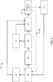
FIG. 1 is a schematic view of an exemplary embodiment of a cooling system for an engine; -
FIG. 2 is a partial top schematic view of the cooling system ofFIG. 1 , in which coolant is shown moving through a diverter fitting and into an engine block and an external cooler; -
FIG. 3 is a perspective view of an exemplary embodiment of a diverter fitting for the cooling system ofFIG. 1 ; -
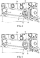
FIG. 4 is a partial perspective view of an exemplary embodiment of an engine block for the cooling system ofFIG. 1 ; -
FIG. 5 is a partial perspective view of the diverter fitting ofFIG. 3 disposed in the engine block ofFIG. 4 ; and -
FIG. 6 is a perspective view of an exemplary embodiment of an external cooler attached to the engine block ofFIG. 4 . - The Detailed Description describes exemplary embodiments of the invention and is not intended to limit the scope of the claims in any way. Indeed, the invention is broader than and unlimited by the exemplary embodiments, and the terms used in the claims have their full ordinary meaning. Features and components of one exemplary embodiment may be incorporated into the other exemplary embodiments. Inventions within the scope of this application may include additional features, or may have less features, than those shown in the exemplary embodiments.
- The present application discloses diverter fittings used for diverting fluid within a cooling system of an engine. While the diverter fitting described herein is described as being used with an engine, it should be understood that the diverter fitting can be used with any other suitable type of cooling system or any other type of system in which fluid is to be diverted.
-
FIG. 1 illustrates an exemplary embodiment of acooling system 100 for an engine 102 (e.g., an internal combustion engine). The cooling system includes apump 104, adiverter fitting 108, anexternal cooler 110, and aradiator 114. Thepump 104 is configured to pump coolant (e.g., water, a mixture that includes water, oil, a mixture that includes oil, or any other suitable type of coolant) through thecooling system 100 to cool down theengine 102, as well as cool down fluid moving through theexternal cooler 110. Thepump 104 can be, for example, a centrifugal pump, or any other suitable type of pump for an engine. Theexternal cooler 110 can be, for example, a transmission cooler, a brake cooler, or any other suitable type of external cooler that receives auxiliary cooling from thecooling system 100 of theengine 102. In addition, theexternal cooler 110 can take any suitable form, such as, for example, the form of a 4-port style cooler, a shell and tube style cooler, a bathtub 2-port style cooler, or any other suitable type of cooler. - Referring to
FIGS. 1 and2 , in certain embodiments, theexternal cooler 110 is connected to an engine block 238 (FIG. 2 ) of theengine 102 such that theexternal cooler 110 is in fluid communication with a cavity 242 (FIG. 2 ) of theengine block 238 and areturn opening 244 of theengine block 238. Thecavity 242 and thereturn opening 244 are each in fluid communication with both an interior coolant passage 240 (FIG. 2 ) of theengine block 238 and an exterior 246 (FIG. 2 ) of theengine block 238. Theinterior coolant passage 240 can be, for example, an entry rail, inlet rail, cylinder head water jacket, or any other coolant passage within the interior of the engine block. - In the illustrated embodiment, the
diverter fitting 108 includes an inlet opening 224 (FIG. 2 ), an outlet opening 226 (FIG. 2 ), and a bypass opening 228 (FIG. 2 ). Theinlet opening 224 is configured to be positioned to receive coolant when thediverter fitting 108 is disposed in thecavity 242 of the engine block. For example, theinlet opening 224 may be in fluid communication with a coolant passage 248 (FIG. 2 ) that is positioned on the exterior surface of theengine block 238 and in fluid communication with thepump 104. In other embodiments, thecoolant passage 248 may be disposed in an interior of theengine block 238, and thecoolant passage 248 is in fluid communication with theexterior 246 of the engine block. - In addition, the
diverter fitting 108 is positioned in thecavity 242 such that the outlet opening 226 is in fluid communication with theexterior 246 of the engine block 238 (and theexternal cooler 110 when theexternal cooler 110 is attached to the engine block 238), and such that thebypass opening 228 is in fluid communication with theinterior coolant passage 240 of theengine block 238. In certain embodiments, thediverter fitting 108 is a modular component that is able to be inserted into and removed from theengine 102. - When the diverter fitting 108 is positioned in the
cavity 242,coolant 232 pumped by thepump 104 through thepassage 248 moves into the inlet opening 224 of the diverter fitting 108 and is split such that a first portion 234 (FIG. 2 ) of thecoolant 232 moves through theoutlet opening 226 and enters theexternal cooler 110, and a second portion 236 (FIG. 2 ) of thecoolant 232 moves through thebypass opening 228 and enters theinterior coolant passage 240 of theengine block 238. Thefirst portion 234 of thecoolant 232 re-enters theinterior coolant passage 240 of theengine block 238 through thereturn opening 244 after moving through theexternal cooler 110 such that thefirst portion 234 and thesecond portion 236 of thecoolant 232 mix in theinterior coolant passage 240 of theengine block 238 at a position adjacent to wherein thefirst portion 234 theinterior coolant passage 240 enters theengine block 238. The diverter fitting 108 is configured to limit the amount of coolant that moves into theexternal cooler 110. - Referring again to
FIG. 1 , after the coolant moves through theexternal cooler 110 and theengine 102, the coolant may move into theradiator 114. The coolant entering theradiator 114 may become heated as a result of moving through theexternal cooler 110 and theengine 102. Theradiator 114 is configured to cool the coolant by transferring heat from the coolant to the surrounding atmosphere. Theradiator 114 may take any suitable form, such as, for example any form of a heat exchange that is capable of transferring heat from the coolant to the atmosphere. After the coolant moves through theradiator 114, the cooled coolant moves back through thepump 104 such that thepump 104 can again pump the coolant through thecooling system 100. - In certain embodiments, the
cooling system 100 includes an oil cooler 106 disposed between thepump 104 and theengine 102. In these embodiments, thepump 104 may first pump coolant through theoil cooler 106 such that the coolant cools oil that is used for lubricating components of theengine 102. Theoil cooler 106 may be attached to an exterior of the engine block 238 (FIG. 2 ) of theengine 102, or theoil cooler 106 may be separated from theengine 102 while remaining in fluid communication with theengine 102. - In some embodiments, the
cooling system 100 includes athermostat housing 112 disposed between and in fluid communication with theengine 102 and theradiator 114. After the coolant moves through theengine 102, the coolant enters thethermostat housing 112. Thethermostat housing 112 houses athermostat 130 that is configured to regulate the temperature of the coolant. If the coolant is below a predetermined temperature, thethermostat 130 maintains a normally-closed position such that the coolant moves through a bypass line 118 (rather than moving into the radiator 114) and into thepump 104. If the coolant is above a predetermined temperature, thethermostat 130 moves to an open position such that the coolant moves into theradiator 114. - In some embodiments, the
pump 104 pumps a portion of the coolant to anaftercooler 116. Coolant moving through theaftercooler 116 cools compressed air leaving a turbocharger compressor (not shown) prior to the air entering theengine 102. In certain embodiments, as shown inFIG. 1 , the coolant moves into theengine 102 after exiting theaftercooler 116 such that the coolant mixes with the coolant that entered the engine through the diverter fitting 108 and theexternal cooler 110. In other embodiments, the coolant from theaftercooler 116 moves into thethermostat housing 112 after exiting theaftercooler 116 such that the coolant mixes with the coolant from theengine 102 in thethermostat housing 112. In each of the embodiments mentioned above, the mixed coolant exits thethermostat housing 112 and moves into either thebypass line 118 or theradiator 114 depending on whether thethermostat 130 is in the open or closed position. - Referring to
FIG. 3 , an exemplary embodiment of a passive diverter fitting 108 includes a base 320 defining aninterior cavity 322, theinlet opening 224, theoutlet opening 226, and thebypass opening 228. The base 320 can be made of, for example, iron, plastic, or any other suitable material. In certain embodiments, the diverter fitting 108 is made by a casting process or an injection molding process, including theinlet opening 224, theoutlet opening 226, and thebypass opening 228. In some embodiments, thebypass opening 228 is not made by the same process used to manufacture the other portions of the diverter fitting 108, but thebypass opening 228 is made after the remaining portions of the diverter fitting are manufactured. For example, thebypass opening 228 can be made by drilling a hole through thebase 320 of thediverter fitting 108. - In the illustrated embodiment, the
base 320 includes acylindrical side wall 374, an openfirst end 370 and a closedsecond end 372. Theoutlet opening 226 is defined by the openfirst end 370 of thebase 320. Thecylindrical side wall 374 includes aninner surface 376 and anouter surface 378, in which theinner surface 376 defines theinterior cavity 322. Theinlet opening 224 extends through thecylindrical side wall 374 such that theinlet opening 224 is in fluid communication with theinterior cavity 322. Theinlet opening 224 may be positioned on the base 320 such that an axis extending through theinlet opening 224 is perpendicular to an axis that extends through theoutlet opening 226. Thebypass opening 228 extends through thecylindrical side wall 374 such that thebypass opening 228 is in fluid communication with theinterior cavity 322. Thebypass opening 228 may be positioned on the base 320 such that an axis extending through theinlet opening 228 is perpendicular to an axis that extends through theoutlet opening 226. In certain embodiments, theinlet opening 224 is positioned on the base substantially opposite the position of the bypass opening 228 (e.g., between about 150 degrees and about 210 degrees about thecylindrical side wall 374 of thebase 320, such as about 180 degrees). Although thebase 320 is described as having a cylindrical shape, it should be understood that the base 320 can take any suitable form that is capable of being positioned in thecavity 242 of the engine block. - In certain embodiments, such as the illustrated embodiment, the diverter fitting 108 includes a protrusion or
rib 380 that extends from theinner surface 376 of thebase 320. Therib 380 is configured to strengthen the base 320 to prevent failure of thediverter fitting 108. For example, coolant entering theinterior cavity 322 of the base 320 through theinlet opening 224 may engage theinner surface 376 of thebase 320 prior to moving through either theoutlet opening 226 or thebypass opening 228, and the pressure exerted on theinner surface 376 by the coolant may cause the diverter fitting 108 to wear over time. Therib 380 is configured to provide stiffness to the base 320 to strengthen the base and prevent failure of the diverter fitting 108 due to this wear. In some embodiments, therib 380 is positioned on theinner surface 376 substantially opposite to the inlet opening 224 (e.g., between about 150 degrees and about 210 degrees about thecylindrical side wall 374 of thebase 320, such as about 180 degrees). Therib 380 may, however, be positioned at any location on the base 320 that allows the diverter fitting to strengthen and prevent failure of the diverter fitting. - The
inlet opening 224, theoutlet opening 226, and thebypass opening 228 may have any suitable size and shape based on the intended use of thediverter fitting 108. That is, theseopenings external cooler 110. In the illustrated embodiment, theoutlet opening 226 and thebypass opening 228 have a circular shape. In certain embodiments, an area defined by thebypass opening 228 is less than an area defined by theoutlet opening 226. For example, the area defined by thebypass opening 228 may be between about 5% and about 25% of the size of the area defined by theoutlet opening 226. - Referring to
FIGS. 3-6 , the diverter fitting 108 is configured to be disposed in acavity 242 of anengine block 238 such that the diverter fitting 108 is positioned to receive coolant from a pump (e.g., pump 104 shown inFIG. 1 ). Referring toFIGS. 4 and 5 , in the illustrated embodiment, theengine block 238 includes an oilcooler cavity 450 disposed on its exterior surface, in which the oilcooler cavity 450 is configured to receive an oil cooler (e.g.,oil cooler 106 shown inFIG. 1 ). Thecavity 242 includes a receivingopening 452 that is in fluid communication with the oilcooler cavity 450 such that the oil cooler is in fluid communication with thecavity 242. The diverter fitting 108 can be positioned in thecavity 242 such that theinlet opening 224 is in fluid communication with the receivingopening 452 and, consequently, in fluid communication with theoil cooler 106. - Referring again to
FIGS. 3-6 , when the diverter fitting 108 is positioned in thecavity 242 of theengine block 238, the outlet opening 226 of the diverter fitting 108 is in fluid communication with an outer opening 454 (FIG. 4 ) of thecavity 242. A portion of the coolant (e.g., theportion 234 ofcoolant 232 shown inFIG. 2 ) that is pumped through theinlet opening 224 and into theinterior cavity 322 of the diverter fitting 108 moves through the outlet opening 226 of the diverter fitting and through theouter opening 454 of thecavity 242. - Referring to
FIG. 4 , thecavity 242 includes aninner opening 456 that is in fluid communication with theinterior coolant passage 240 of theengine block 238. Referring toFIGS. 3-5 , when the diverter fitting 108 is positioned within thecavity 242 of theengine block 238, thebypass opening 228 is in fluid communication with theinner opening 456 of thecavity 242. A portion of the coolant (e.g., theportion 236 ofcoolant 232 shown inFIG. 2 ) that is pumped through theinlet opening 224 and into theinterior cavity 322 of the diverter fitting 108 moves through thebypass opening 228 and through theinner opening 456 of thecavity 242 such that the coolant moves into theinterior coolant passage 240 of theengine block 238. - Referring to
FIGS. 4-6 , theexternal cooler 110 is attached to the exterior surface of theengine block 238 such that acoolant inlet 658 of theexternal cooler 110 is in fluid communication with theouter opening 454 of thecavity 242, and such that an outlet (not shown) of theexternal cooler 110 is in fluid communication with the return opening 244 of theengine block 238. After a portion of the coolant (e.g., theportion 234 ofcoolant 232 shown inFIG. 2 ) moves through theexternal cooler 110, the coolant moves into theinterior coolant passage 240 of theengine block 238 and mixes with a portion of the coolant (e.g., theportion 236 ofcoolant 232 shown inFIG. 2 ) that entered theengine block 238 through thebypass opening 228 of thediverter fitting 108. In various embodiments, theexternal cooler 110 includes aninlet conduit 660 and anoutlet conduit 662, in which a heated fluid (e.g., hydraulic fluid) moves from theinlet conduit 660, through theexternal cooler 110, and exits through theoutlet conduit 662. The heated fluid is cooled by the coolant moving through the external cooler. Theexternal cooler 110 can be, for example, a transmission cooler, a brake cooler, or any other suitable type of external cooler that receives auxiliary cooling from thecooling system 100. In addition, theexternal cooler 110 can take any suitable form, such as, for example, the form of a 4-port style cooler, a shell and tube style cooler, a bathtub 2-port style cooler, or any other suitable type of cooler. - Current cooling systems that include an external cooler move the entire amount of coolant into the external cooler prior to the coolant entering the interior of the engine block. The
external cooler 110 may be, for example, a transmission cooler or a brake cooler. Transmission and brake coolers, however, typically take the form of shell and tube style coolers, and shell and tube style coolers are typically too large to be able to fit on an engine, which means these coolers often need to be located elsewhere on a chassis of a machine. External coolers may, however, take the form of a 4-port style cooler. In these situations, the external cooler can be attached to the engine because a 4-port style cooler does not have the same size restrictions as the shell and tube style cooler. - In certain situations, it is advantageous to have a system in which the entire amount of coolant is not moved through the external cooler, but only a portion of the coolant is moved through the external cooler. For example, if a 4-port style external cooler is used and the entire amount of coolant is moved through the external cooler, the external cooler can be over-cooled and/or cause a pressure restriction for the pump that is pumping the coolant through the cooling system. In addition, moving the entire amount of coolant through the 4-port style cooler is a waste of power for the cooling system. In situations in which a shell and tube external cooler is used, the shell and tube cooler may not require the entire coolant for proper cooling, which means it is a waste of power to move the entire amount of coolant through the external cooler. While a 4-port external cooler and a shell and tube external cooler are described above, it should be understood that any type of external cooler could be used in situations in which it is not advantageous to move the entire amount of coolant through the external cooler.
- The disclosed diverter fitting 108 is configured to be used in cooling systems for engines to limit the amount of coolant that moves into an external cooler. Referring to
FIG. 2 , when the diverter fitting 108 is positioned in thecavity 242 of theengine 102,coolant 232 pumped through thepassage 248 moves into the inlet opening 224 of the diverter fitting 108 such that afirst portion 234 of thecoolant 232 moves through theoutlet opening 226 and enters theexternal cooler 110, and asecond portion 236 of thecoolant 232 moves through thebypass opening 228 and enters theinterior coolant passage 240 of theengine block 238. Thefirst portion 234 of thecoolant 232 enters theinterior coolant passage 240 through thereturn opening 244 after moving through theexternal cooler 110 such that thefirst portion 234 and thesecond portion 236 of thecoolant 232 mix in theinterior coolant passage 240 of theengine block 238. The sizes of theoutlet opening 226 and thebypass opening 228 dictate the amount of coolant that is sent to theexternal cooler 110. The diverter fitting 108 is configured to limit the amount of coolant that moves into theexternal cooler 110, thus preventing over-cooling of the external cooler, a pressure restriction for the water pump, and a waste of power of the cooling system. - In certain embodiments, the diverter fitting 108 is modular, which is advantageous because it allows the diverter fitting to be removed and replaced, if needed, as well as allowing the diverter fitting to be used on multiple engines. The replaceability of the diverter fitting 108 is advantageous because it allows
diverter fittings 108 having differentsize outlet openings 226 andbypass openings 228 to be used depending on the situation in which the diverter fitting is being used. For example, if a situation requires more coolant to be supplied to the external cooler, a diverter fitting with asmaller bypass opening 228 can be used, which will allow more of the coolant to move through theoutlet opening 226 and into theexternal cooler 110. In some situations, thecooling system 100 may not include anexternal cooler 110, and the diverter fitting 108 is not needed. In these situations, a modular diverter fitting 108 is advantageous because the diverter fitting can be removed or omitted, and theopenings engine block 238 can be capped off. In addition, the passive design of the diverter fitting 108 is advantageous because it does not require active controlling of the diverter fitting 108 during use of the cooling system. - It will be appreciated that the foregoing description provides examples of the disclosed system and technique. However, it is contemplated that other implementations of the disclosure may differ in detail from the foregoing examples. All references to the disclosure or examples thereof are intended to reference the particular example being discussed at that point and are not intended to imply any limitation as to the scope of the disclosure more generally. All language of distinction and disparagement with respect to certain features is intended to indicate a lack of preference for those features, but not to exclude such from the scope of the disclosure entirely unless otherwise indicated. Accordingly, this disclosure includes all modification and equivalents of the subject matter recited in the claims appended hereto as permitted by applicable law. Moreover, any combination of the above-described elements in all possible variations thereof is encompassed by the disclosure unless otherwise indicated herein or otherwise clearly contradicted by context.
Claims (10)
- A passive diverter fitting (108) for a cooling system (100) of an engine (102), the engine comprising an engine block (238) defining a block interior coolant passage (240), a cavity (242) in fluid communication with the block interior coolant passage, and a return opening (244) in fluid communication with the block interior coolant passage, the diverter fitting comprising:a base (320) defining an interior cavity (322), wherein the base is configured to be removably disposed in the cavity of the engine block;an inlet opening (224) extending through the base such that the inlet opening is in fluid communication with the interior cavity, wherein the inlet opening is positioned to receive coolant when the passive diverter fitting is disposed in the cavity of the engine block;an outlet opening (226) in fluid communication with the interior cavity, wherein the outlet opening is in fluid communication with the area exterior to the engine block when the passive diverter fitting is disposed in the cavity of the engine block; anda bypass opening (228) extending through the base such that the bypass opening is in fluid communication with the interior cavity, wherein the bypass opening is in fluid communication with the block interior coolant passage when the passive diverter fitting is disposed in the cavity of the engine block.
- The passive diverter fitting according to claim 1, wherein the engine block comprises an oil cooler cavity (450) on an exterior surface of the engine block, and wherein the inlet opening of the diverter fitting is in fluid communication with the oil cooler cavity when the passive diverter fitting is disposed in the outlet cavity of the engine block.
- The passive diverter fitting according to claim 1, wherein the base comprises at least one of iron and plastic.
- The passive diverter fitting according to claim 1, wherein a first area defined by the bypass opening is between about 5% and about 25% of a second area defined by the outlet opening.
- The passive diverter fitting according to claim 1, wherein the base comprises a cylindrical wall (374), an open first end (370), and a closed second end (372); and wherein the inlet opening and the bypass opening extend through the cylindrical wall.
- The passive diverter fitting according to claim 5, wherein the bypass opening is a drilled hole that extends through the cylindrical wall of the base.
- The passive diverter fitting according to claim 6, wherein the inlet opening is positioned on the base such that that inlet opening is between about 150 degrees and about 210 degrees away from the bypass opening relative to the cylindrical wall of the base.
- The passive diverter fitting according to claim 1, wherein the base is made by injection molding.
- The passive diverter fitting according to claim 1, further comprising a rib (380) extending from an inner surface (376) of the base.
- The passive diverter fitting according to claim 9, wherein the rib is positioned on the base such that the rib is between about 150 degrees and about 210 degrees away from the inlet opening relative to the cylindrical wall of the base.
Applications Claiming Priority (1)
| Application Number | Priority Date | Filing Date | Title |
|---|---|---|---|
| US16/789,844 US11525385B2 (en) | 2020-02-13 | 2020-02-13 | Diverter fittings for cooling systems of an engine |
Publications (2)
| Publication Number | Publication Date |
|---|---|
| EP3865688A1 true EP3865688A1 (en) | 2021-08-18 |
| EP3865688B1 EP3865688B1 (en) | 2023-10-18 |
Family
ID=74236112
Family Applications (1)
| Application Number | Title | Priority Date | Filing Date |
|---|---|---|---|
| EP21153363.3A Active EP3865688B1 (en) | 2020-02-13 | 2021-01-26 | Diverter fittings for cooling systems of an engine |
Country Status (3)
| Country | Link |
|---|---|
| US (1) | US11525385B2 (en) |
| EP (1) | EP3865688B1 (en) |
| CN (1) | CN113250803B (en) |
Citations (7)
| Publication number | Priority date | Publication date | Assignee | Title |
|---|---|---|---|---|
| GB1279132A (en) * | 1969-04-02 | 1972-06-28 | Chrysler United Kingdom Ltd Fo | Improvements in or relating to internal combustion engines |
| WO1996003574A1 (en) * | 1994-07-26 | 1996-02-08 | Daewoo Motor Co., Ltd. | Cooling system of an internal combustion engine |
| WO1996029509A1 (en) * | 1995-03-17 | 1996-09-26 | Standard-Thomson Corporation | Electronically controlled engine cooling apparatus |
| DE10127711A1 (en) | 2001-06-07 | 2003-01-02 | Bosch Gmbh Robert | Internal combustion engine three-way valve uses distribution channel and choke surface to form mixing section to linearize flow to cooler depending on choke opening angles. |
| WO2015168313A1 (en) * | 2014-04-30 | 2015-11-05 | Cummins Inc. | System and method for optimizing the integration of engines and vehicle driveline retarders |
| WO2018033669A1 (en) * | 2016-08-16 | 2018-02-22 | Renault S.A.S. | Outer conduit of an outlet of a volute of a heat transfer pump of a heat engine of a vehicle |
| DE102018122702A1 (en) * | 2018-09-17 | 2020-03-19 | Man Truck & Bus Se | Cooling system and method for configuring a cooling system |
Family Cites Families (10)
| Publication number | Priority date | Publication date | Assignee | Title |
|---|---|---|---|---|
| US6634322B2 (en) * | 2001-04-12 | 2003-10-21 | Cold Fire, Llc | Heat exchanger tempering valve |
| US6539899B1 (en) * | 2002-02-11 | 2003-04-01 | Visteon Global Technologies, Inc. | Rotary valve for single-point coolant diversion in engine cooling system |
| US8376029B2 (en) | 2002-10-29 | 2013-02-19 | Duramax Marine, Llc | Keel cooler with fluid flow diverter |
| JP4168417B2 (en) | 2002-11-18 | 2008-10-22 | 株式会社山武 | Fluid detection device |
| US6955141B2 (en) * | 2003-08-06 | 2005-10-18 | General Motors Corporation | Engine cooling system |
| US20060032844A1 (en) * | 2004-08-13 | 2006-02-16 | Kingrey William R | Vehicle coolant heating system |
| US7343882B2 (en) | 2006-04-07 | 2008-03-18 | Emp Advanced Development, Inc. | Fluid valve |
| WO2007136517A2 (en) | 2006-05-15 | 2007-11-29 | Hollis Thomas J | Digital rotary control valve |
| US8978596B2 (en) * | 2012-06-29 | 2015-03-17 | GM Global Technology Operations LLC | Powertrain cooling system with cooling flow modes |
| CN204041199U (en) | 2014-08-14 | 2014-12-24 | 安徽水利水电职业技术学院 | The automatically controlled auxiliary coolant system of a kind of motor combined type |
-
2020
- 2020-02-13 US US16/789,844 patent/US11525385B2/en active Active
-
2021
- 2021-01-26 EP EP21153363.3A patent/EP3865688B1/en active Active
- 2021-02-09 CN CN202110181633.7A patent/CN113250803B/en active Active
Patent Citations (7)
| Publication number | Priority date | Publication date | Assignee | Title |
|---|---|---|---|---|
| GB1279132A (en) * | 1969-04-02 | 1972-06-28 | Chrysler United Kingdom Ltd Fo | Improvements in or relating to internal combustion engines |
| WO1996003574A1 (en) * | 1994-07-26 | 1996-02-08 | Daewoo Motor Co., Ltd. | Cooling system of an internal combustion engine |
| WO1996029509A1 (en) * | 1995-03-17 | 1996-09-26 | Standard-Thomson Corporation | Electronically controlled engine cooling apparatus |
| DE10127711A1 (en) | 2001-06-07 | 2003-01-02 | Bosch Gmbh Robert | Internal combustion engine three-way valve uses distribution channel and choke surface to form mixing section to linearize flow to cooler depending on choke opening angles. |
| WO2015168313A1 (en) * | 2014-04-30 | 2015-11-05 | Cummins Inc. | System and method for optimizing the integration of engines and vehicle driveline retarders |
| WO2018033669A1 (en) * | 2016-08-16 | 2018-02-22 | Renault S.A.S. | Outer conduit of an outlet of a volute of a heat transfer pump of a heat engine of a vehicle |
| DE102018122702A1 (en) * | 2018-09-17 | 2020-03-19 | Man Truck & Bus Se | Cooling system and method for configuring a cooling system |
Also Published As
| Publication number | Publication date |
|---|---|
| US11525385B2 (en) | 2022-12-13 |
| CN113250803A (en) | 2021-08-13 |
| CN113250803B (en) | 2025-01-07 |
| EP3865688B1 (en) | 2023-10-18 |
| US20210254539A1 (en) | 2021-08-19 |
Similar Documents
| Publication | Publication Date | Title |
|---|---|---|
| US6634323B2 (en) | Cooling units for motor vehicles | |
| CN106014591B (en) | Control device for controlling coolant flow of split cooling system | |
| US7207298B2 (en) | Cooling system for an engine | |
| US6681805B2 (en) | Automotive coolant control valve | |
| CN212979863U (en) | Cooling water comprehensive heat management device for vehicle | |
| DE102008034502A1 (en) | Cooling pump for internal combustion engine and cooling system, in which the cooling pump is used | |
| US8944017B2 (en) | Powertrain cooling system with cooling and heating modes for heat exchangers | |
| EP1270896B1 (en) | Method and device for cooling charge air and hydraulic oil | |
| CN102465751A (en) | Hybrid cooling system for internal combustion engine | |
| KR101784428B1 (en) | Cooling system in a vehicle | |
| US9458967B2 (en) | Integrated lubrication cooling system | |
| EP3865688B1 (en) | Diverter fittings for cooling systems of an engine | |
| EP0750099B1 (en) | Thermostat housing for internal combustion engine | |
| US11047291B2 (en) | Engine cooling device and engine system | |
| US20220372907A1 (en) | Fluidic control device of a vehicle | |
| US7096830B2 (en) | Mounting arrangement for electric water pump | |
| EP3800335B1 (en) | Internal combustion engine provided with a liquid cooling system | |
| US20030116104A1 (en) | Liquid cooled power steering pump | |
| KR20150095927A (en) | Valve, particularly an exhaust gas recirculation valve | |
| EP1941165B1 (en) | Cooling system for a work machine | |
| KR102335323B1 (en) | Cooling system for engine | |
| FR2863680B1 (en) | THERMAL CONTROL VALVE FOR A FLUID CIRCUIT, ESPECIALLY FOR A COOLING CIRCUIT OF AN ENGINE. | |
| JP6702508B2 (en) | Outer pipe of volute outlet of heat transfer pump of vehicle heat engine | |
| EP4741643A1 (en) | Engine system with thermostat arrangement for controlling coolant flow through a bypass circuit | |
| CN110552776A (en) | Temperature regulator with integrated casing, thermostatic valve and valve seat |
Legal Events
| Date | Code | Title | Description |
|---|---|---|---|
| PUAI | Public reference made under article 153(3) epc to a published international application that has entered the european phase |
Free format text: ORIGINAL CODE: 0009012 |
|
| STAA | Information on the status of an ep patent application or granted ep patent |
Free format text: STATUS: THE APPLICATION HAS BEEN PUBLISHED |
|
| AK | Designated contracting states |
Kind code of ref document: A1 Designated state(s): AL AT BE BG CH CY CZ DE DK EE ES FI FR GB GR HR HU IE IS IT LI LT LU LV MC MK MT NL NO PL PT RO RS SE SI SK SM TR |
|
| STAA | Information on the status of an ep patent application or granted ep patent |
Free format text: STATUS: REQUEST FOR EXAMINATION WAS MADE |
|
| 17P | Request for examination filed |
Effective date: 20220214 |
|
| RBV | Designated contracting states (corrected) |
Designated state(s): AL AT BE BG CH CY CZ DE DK EE ES FI FR GB GR HR HU IE IS IT LI LT LU LV MC MK MT NL NO PL PT RO RS SE SI SK SM TR |
|
| GRAP | Despatch of communication of intention to grant a patent |
Free format text: ORIGINAL CODE: EPIDOSNIGR1 |
|
| STAA | Information on the status of an ep patent application or granted ep patent |
Free format text: STATUS: GRANT OF PATENT IS INTENDED |
|
| INTG | Intention to grant announced |
Effective date: 20230712 |
|
| GRAS | Grant fee paid |
Free format text: ORIGINAL CODE: EPIDOSNIGR3 |
|
| P01 | Opt-out of the competence of the unified patent court (upc) registered |
Effective date: 20230809 |
|
| GRAA | (expected) grant |
Free format text: ORIGINAL CODE: 0009210 |
|
| STAA | Information on the status of an ep patent application or granted ep patent |
Free format text: STATUS: THE PATENT HAS BEEN GRANTED |
|
| AK | Designated contracting states |
Kind code of ref document: B1 Designated state(s): AL AT BE BG CH CY CZ DE DK EE ES FI FR GB GR HR HU IE IS IT LI LT LU LV MC MK MT NL NO PL PT RO RS SE SI SK SM TR |
|
| REG | Reference to a national code |
Ref country code: GB Ref legal event code: FG4D |
|
| REG | Reference to a national code |
Ref country code: CH Ref legal event code: EP |
|
| REG | Reference to a national code |
Ref country code: IE Ref legal event code: FG4D |
|
| REG | Reference to a national code |
Ref country code: DE Ref legal event code: R096 Ref document number: 602021005877 Country of ref document: DE |
|
| REG | Reference to a national code |
Ref country code: LT Ref legal event code: MG9D |
|
| REG | Reference to a national code |
Ref country code: NL Ref legal event code: MP Effective date: 20231018 |
|
| REG | Reference to a national code |
Ref country code: AT Ref legal event code: MK05 Ref document number: 1622669 Country of ref document: AT Kind code of ref document: T Effective date: 20231018 |
|
| PG25 | Lapsed in a contracting state [announced via postgrant information from national office to epo] |
Ref country code: NL Free format text: LAPSE BECAUSE OF FAILURE TO SUBMIT A TRANSLATION OF THE DESCRIPTION OR TO PAY THE FEE WITHIN THE PRESCRIBED TIME-LIMIT Effective date: 20231018 |
|
| PG25 | Lapsed in a contracting state [announced via postgrant information from national office to epo] |
Ref country code: GR Free format text: LAPSE BECAUSE OF FAILURE TO SUBMIT A TRANSLATION OF THE DESCRIPTION OR TO PAY THE FEE WITHIN THE PRESCRIBED TIME-LIMIT Effective date: 20240119 |
|
| PG25 | Lapsed in a contracting state [announced via postgrant information from national office to epo] |
Ref country code: IS Free format text: LAPSE BECAUSE OF FAILURE TO SUBMIT A TRANSLATION OF THE DESCRIPTION OR TO PAY THE FEE WITHIN THE PRESCRIBED TIME-LIMIT Effective date: 20240218 |
|
| PG25 | Lapsed in a contracting state [announced via postgrant information from national office to epo] |
Ref country code: LT Free format text: LAPSE BECAUSE OF FAILURE TO SUBMIT A TRANSLATION OF THE DESCRIPTION OR TO PAY THE FEE WITHIN THE PRESCRIBED TIME-LIMIT Effective date: 20231018 |
|
| PG25 | Lapsed in a contracting state [announced via postgrant information from national office to epo] |
Ref country code: AT Free format text: LAPSE BECAUSE OF FAILURE TO SUBMIT A TRANSLATION OF THE DESCRIPTION OR TO PAY THE FEE WITHIN THE PRESCRIBED TIME-LIMIT Effective date: 20231018 |
|
| PG25 | Lapsed in a contracting state [announced via postgrant information from national office to epo] |
Ref country code: ES Free format text: LAPSE BECAUSE OF FAILURE TO SUBMIT A TRANSLATION OF THE DESCRIPTION OR TO PAY THE FEE WITHIN THE PRESCRIBED TIME-LIMIT Effective date: 20231018 |
|
| PG25 | Lapsed in a contracting state [announced via postgrant information from national office to epo] |
Ref country code: LT Free format text: LAPSE BECAUSE OF FAILURE TO SUBMIT A TRANSLATION OF THE DESCRIPTION OR TO PAY THE FEE WITHIN THE PRESCRIBED TIME-LIMIT Effective date: 20231018 Ref country code: IS Free format text: LAPSE BECAUSE OF FAILURE TO SUBMIT A TRANSLATION OF THE DESCRIPTION OR TO PAY THE FEE WITHIN THE PRESCRIBED TIME-LIMIT Effective date: 20240218 Ref country code: GR Free format text: LAPSE BECAUSE OF FAILURE TO SUBMIT A TRANSLATION OF THE DESCRIPTION OR TO PAY THE FEE WITHIN THE PRESCRIBED TIME-LIMIT Effective date: 20240119 Ref country code: ES Free format text: LAPSE BECAUSE OF FAILURE TO SUBMIT A TRANSLATION OF THE DESCRIPTION OR TO PAY THE FEE WITHIN THE PRESCRIBED TIME-LIMIT Effective date: 20231018 Ref country code: BG Free format text: LAPSE BECAUSE OF FAILURE TO SUBMIT A TRANSLATION OF THE DESCRIPTION OR TO PAY THE FEE WITHIN THE PRESCRIBED TIME-LIMIT Effective date: 20240118 Ref country code: AT Free format text: LAPSE BECAUSE OF FAILURE TO SUBMIT A TRANSLATION OF THE DESCRIPTION OR TO PAY THE FEE WITHIN THE PRESCRIBED TIME-LIMIT Effective date: 20231018 Ref country code: PT Free format text: LAPSE BECAUSE OF FAILURE TO SUBMIT A TRANSLATION OF THE DESCRIPTION OR TO PAY THE FEE WITHIN THE PRESCRIBED TIME-LIMIT Effective date: 20240219 |
|
| PG25 | Lapsed in a contracting state [announced via postgrant information from national office to epo] |
Ref country code: SE Free format text: LAPSE BECAUSE OF FAILURE TO SUBMIT A TRANSLATION OF THE DESCRIPTION OR TO PAY THE FEE WITHIN THE PRESCRIBED TIME-LIMIT Effective date: 20231018 Ref country code: RS Free format text: LAPSE BECAUSE OF FAILURE TO SUBMIT A TRANSLATION OF THE DESCRIPTION OR TO PAY THE FEE WITHIN THE PRESCRIBED TIME-LIMIT Effective date: 20231018 Ref country code: PL Free format text: LAPSE BECAUSE OF FAILURE TO SUBMIT A TRANSLATION OF THE DESCRIPTION OR TO PAY THE FEE WITHIN THE PRESCRIBED TIME-LIMIT Effective date: 20231018 Ref country code: NO Free format text: LAPSE BECAUSE OF FAILURE TO SUBMIT A TRANSLATION OF THE DESCRIPTION OR TO PAY THE FEE WITHIN THE PRESCRIBED TIME-LIMIT Effective date: 20240118 Ref country code: LV Free format text: LAPSE BECAUSE OF FAILURE TO SUBMIT A TRANSLATION OF THE DESCRIPTION OR TO PAY THE FEE WITHIN THE PRESCRIBED TIME-LIMIT Effective date: 20231018 Ref country code: HR Free format text: LAPSE BECAUSE OF FAILURE TO SUBMIT A TRANSLATION OF THE DESCRIPTION OR TO PAY THE FEE WITHIN THE PRESCRIBED TIME-LIMIT Effective date: 20231018 |
|
| PG25 | Lapsed in a contracting state [announced via postgrant information from national office to epo] |
Ref country code: DK Free format text: LAPSE BECAUSE OF FAILURE TO SUBMIT A TRANSLATION OF THE DESCRIPTION OR TO PAY THE FEE WITHIN THE PRESCRIBED TIME-LIMIT Effective date: 20231018 |
|
| REG | Reference to a national code |
Ref country code: DE Ref legal event code: R097 Ref document number: 602021005877 Country of ref document: DE |
|
| PG25 | Lapsed in a contracting state [announced via postgrant information from national office to epo] |
Ref country code: CZ Free format text: LAPSE BECAUSE OF FAILURE TO SUBMIT A TRANSLATION OF THE DESCRIPTION OR TO PAY THE FEE WITHIN THE PRESCRIBED TIME-LIMIT Effective date: 20231018 |
|
| PG25 | Lapsed in a contracting state [announced via postgrant information from national office to epo] |
Ref country code: SK Free format text: LAPSE BECAUSE OF FAILURE TO SUBMIT A TRANSLATION OF THE DESCRIPTION OR TO PAY THE FEE WITHIN THE PRESCRIBED TIME-LIMIT Effective date: 20231018 |
|
| PG25 | Lapsed in a contracting state [announced via postgrant information from national office to epo] |
Ref country code: SM Free format text: LAPSE BECAUSE OF FAILURE TO SUBMIT A TRANSLATION OF THE DESCRIPTION OR TO PAY THE FEE WITHIN THE PRESCRIBED TIME-LIMIT Effective date: 20231018 Ref country code: SK Free format text: LAPSE BECAUSE OF FAILURE TO SUBMIT A TRANSLATION OF THE DESCRIPTION OR TO PAY THE FEE WITHIN THE PRESCRIBED TIME-LIMIT Effective date: 20231018 Ref country code: RO Free format text: LAPSE BECAUSE OF FAILURE TO SUBMIT A TRANSLATION OF THE DESCRIPTION OR TO PAY THE FEE WITHIN THE PRESCRIBED TIME-LIMIT Effective date: 20231018 Ref country code: IT Free format text: LAPSE BECAUSE OF FAILURE TO SUBMIT A TRANSLATION OF THE DESCRIPTION OR TO PAY THE FEE WITHIN THE PRESCRIBED TIME-LIMIT Effective date: 20231018 Ref country code: EE Free format text: LAPSE BECAUSE OF FAILURE TO SUBMIT A TRANSLATION OF THE DESCRIPTION OR TO PAY THE FEE WITHIN THE PRESCRIBED TIME-LIMIT Effective date: 20231018 Ref country code: DK Free format text: LAPSE BECAUSE OF FAILURE TO SUBMIT A TRANSLATION OF THE DESCRIPTION OR TO PAY THE FEE WITHIN THE PRESCRIBED TIME-LIMIT Effective date: 20231018 Ref country code: CZ Free format text: LAPSE BECAUSE OF FAILURE TO SUBMIT A TRANSLATION OF THE DESCRIPTION OR TO PAY THE FEE WITHIN THE PRESCRIBED TIME-LIMIT Effective date: 20231018 |
|
| PLBE | No opposition filed within time limit |
Free format text: ORIGINAL CODE: 0009261 |
|
| STAA | Information on the status of an ep patent application or granted ep patent |
Free format text: STATUS: NO OPPOSITION FILED WITHIN TIME LIMIT |
|
| PG25 | Lapsed in a contracting state [announced via postgrant information from national office to epo] |
Ref country code: MC Free format text: LAPSE BECAUSE OF FAILURE TO SUBMIT A TRANSLATION OF THE DESCRIPTION OR TO PAY THE FEE WITHIN THE PRESCRIBED TIME-LIMIT Effective date: 20231018 |
|
| PG25 | Lapsed in a contracting state [announced via postgrant information from national office to epo] |
Ref country code: MC Free format text: LAPSE BECAUSE OF FAILURE TO SUBMIT A TRANSLATION OF THE DESCRIPTION OR TO PAY THE FEE WITHIN THE PRESCRIBED TIME-LIMIT Effective date: 20231018 |
|
| REG | Reference to a national code |
Ref country code: CH Ref legal event code: PL |
|
| PG25 | Lapsed in a contracting state [announced via postgrant information from national office to epo] |
Ref country code: LU Free format text: LAPSE BECAUSE OF NON-PAYMENT OF DUE FEES Effective date: 20240126 |
|
| 26N | No opposition filed |
Effective date: 20240719 |
|
| PG25 | Lapsed in a contracting state [announced via postgrant information from national office to epo] |
Ref country code: LU Free format text: LAPSE BECAUSE OF NON-PAYMENT OF DUE FEES Effective date: 20240126 |
|
| PG25 | Lapsed in a contracting state [announced via postgrant information from national office to epo] |
Ref country code: BE Free format text: LAPSE BECAUSE OF NON-PAYMENT OF DUE FEES Effective date: 20240131 |
|
| PG25 | Lapsed in a contracting state [announced via postgrant information from national office to epo] |
Ref country code: FR Free format text: LAPSE BECAUSE OF NON-PAYMENT OF DUE FEES Effective date: 20240131 |
|
| PG25 | Lapsed in a contracting state [announced via postgrant information from national office to epo] |
Ref country code: CH Free format text: LAPSE BECAUSE OF NON-PAYMENT OF DUE FEES Effective date: 20240131 |
|
| PG25 | Lapsed in a contracting state [announced via postgrant information from national office to epo] |
Ref country code: SI Free format text: LAPSE BECAUSE OF FAILURE TO SUBMIT A TRANSLATION OF THE DESCRIPTION OR TO PAY THE FEE WITHIN THE PRESCRIBED TIME-LIMIT Effective date: 20231018 |
|
| PG25 | Lapsed in a contracting state [announced via postgrant information from national office to epo] |
Ref country code: SI Free format text: LAPSE BECAUSE OF FAILURE TO SUBMIT A TRANSLATION OF THE DESCRIPTION OR TO PAY THE FEE WITHIN THE PRESCRIBED TIME-LIMIT Effective date: 20231018 Ref country code: FR Free format text: LAPSE BECAUSE OF NON-PAYMENT OF DUE FEES Effective date: 20240131 Ref country code: CH Free format text: LAPSE BECAUSE OF NON-PAYMENT OF DUE FEES Effective date: 20240131 Ref country code: BE Free format text: LAPSE BECAUSE OF NON-PAYMENT OF DUE FEES Effective date: 20240131 |
|
| REG | Reference to a national code |
Ref country code: BE Ref legal event code: MM Effective date: 20240131 |
|
| PG25 | Lapsed in a contracting state [announced via postgrant information from national office to epo] |
Ref country code: IE Free format text: LAPSE BECAUSE OF NON-PAYMENT OF DUE FEES Effective date: 20240126 |
|
| PG25 | Lapsed in a contracting state [announced via postgrant information from national office to epo] |
Ref country code: IE Free format text: LAPSE BECAUSE OF NON-PAYMENT OF DUE FEES Effective date: 20240126 |
|
| PG25 | Lapsed in a contracting state [announced via postgrant information from national office to epo] |
Ref country code: CY Free format text: LAPSE BECAUSE OF FAILURE TO SUBMIT A TRANSLATION OF THE DESCRIPTION OR TO PAY THE FEE WITHIN THE PRESCRIBED TIME-LIMIT; INVALID AB INITIO Effective date: 20210126 |
|
| PG25 | Lapsed in a contracting state [announced via postgrant information from national office to epo] |
Ref country code: HU Free format text: LAPSE BECAUSE OF FAILURE TO SUBMIT A TRANSLATION OF THE DESCRIPTION OR TO PAY THE FEE WITHIN THE PRESCRIBED TIME-LIMIT; INVALID AB INITIO Effective date: 20210126 |
|
| PG25 | Lapsed in a contracting state [announced via postgrant information from national office to epo] |
Ref country code: FI Free format text: LAPSE BECAUSE OF FAILURE TO SUBMIT A TRANSLATION OF THE DESCRIPTION OR TO PAY THE FEE WITHIN THE PRESCRIBED TIME-LIMIT Effective date: 20231019 |
|
| PG25 | Lapsed in a contracting state [announced via postgrant information from national office to epo] |
Ref country code: TR Free format text: LAPSE BECAUSE OF FAILURE TO SUBMIT A TRANSLATION OF THE DESCRIPTION OR TO PAY THE FEE WITHIN THE PRESCRIBED TIME-LIMIT Effective date: 20231018 |
|
| PGFP | Annual fee paid to national office [announced via postgrant information from national office to epo] |
Ref country code: GB Payment date: 20251220 Year of fee payment: 6 |
|
| PGFP | Annual fee paid to national office [announced via postgrant information from national office to epo] |
Ref country code: DE Payment date: 20251217 Year of fee payment: 6 |