EP3865679A1 - Borescope port engine fluid wash - Google Patents
Borescope port engine fluid wash Download PDFInfo
- Publication number
- EP3865679A1 EP3865679A1 EP21156707.8A EP21156707A EP3865679A1 EP 3865679 A1 EP3865679 A1 EP 3865679A1 EP 21156707 A EP21156707 A EP 21156707A EP 3865679 A1 EP3865679 A1 EP 3865679A1
- Authority
- EP
- European Patent Office
- Prior art keywords
- base
- wash
- spray nozzle
- fluid
- component
- Prior art date
- Legal status (The legal status is an assumption and is not a legal conclusion. Google has not performed a legal analysis and makes no representation as to the accuracy of the status listed.)
- Granted
Links
Images


Classifications
-
- F—MECHANICAL ENGINEERING; LIGHTING; HEATING; WEAPONS; BLASTING
- F01—MACHINES OR ENGINES IN GENERAL; ENGINE PLANTS IN GENERAL; STEAM ENGINES
- F01D—NON-POSITIVE DISPLACEMENT MACHINES OR ENGINES, e.g. STEAM TURBINES
- F01D25/00—Component parts, details, or accessories, not provided for in, or of interest apart from, other groups
- F01D25/002—Cleaning of turbomachines
-
- B—PERFORMING OPERATIONS; TRANSPORTING
- B08—CLEANING
- B08B—CLEANING IN GENERAL; PREVENTION OF FOULING IN GENERAL
- B08B9/00—Cleaning hollow articles by methods or apparatus specially adapted thereto
- B08B9/02—Cleaning pipes or tubes or systems of pipes or tubes
- B08B9/027—Cleaning the internal surfaces; Removal of blockages
- B08B9/032—Cleaning the internal surfaces; Removal of blockages by the mechanical action of a moving fluid, e.g. by flushing
- B08B9/0321—Cleaning the internal surfaces; Removal of blockages by the mechanical action of a moving fluid, e.g. by flushing using pressurised, pulsating or purging fluid
-
- B—PERFORMING OPERATIONS; TRANSPORTING
- B08—CLEANING
- B08B—CLEANING IN GENERAL; PREVENTION OF FOULING IN GENERAL
- B08B9/00—Cleaning hollow articles by methods or apparatus specially adapted thereto
- B08B9/08—Cleaning containers, e.g. tanks
- B08B9/093—Cleaning containers, e.g. tanks by the force of jets or sprays
- B08B9/0936—Cleaning containers, e.g. tanks by the force of jets or sprays using rotating jets
-
- B—PERFORMING OPERATIONS; TRANSPORTING
- B08—CLEANING
- B08B—CLEANING IN GENERAL; PREVENTION OF FOULING IN GENERAL
- B08B2209/00—Details of machines or methods for cleaning hollow articles
- B08B2209/02—Details of apparatuses or methods for cleaning pipes or tubes
- B08B2209/027—Details of apparatuses or methods for cleaning pipes or tubes for cleaning the internal surfaces
- B08B2209/032—Details of apparatuses or methods for cleaning pipes or tubes for cleaning the internal surfaces by the mechanical action of a moving fluid
-
- F—MECHANICAL ENGINEERING; LIGHTING; HEATING; WEAPONS; BLASTING
- F05—INDEXING SCHEMES RELATING TO ENGINES OR PUMPS IN VARIOUS SUBCLASSES OF CLASSES F01-F04
- F05D—INDEXING SCHEME FOR ASPECTS RELATING TO NON-POSITIVE-DISPLACEMENT MACHINES OR ENGINES, GAS-TURBINES OR JET-PROPULSION PLANTS
- F05D2220/00—Application
- F05D2220/30—Application in turbines
- F05D2220/32—Application in turbines in gas turbines
-
- F—MECHANICAL ENGINEERING; LIGHTING; HEATING; WEAPONS; BLASTING
- F05—INDEXING SCHEMES RELATING TO ENGINES OR PUMPS IN VARIOUS SUBCLASSES OF CLASSES F01-F04
- F05D—INDEXING SCHEME FOR ASPECTS RELATING TO NON-POSITIVE-DISPLACEMENT MACHINES OR ENGINES, GAS-TURBINES OR JET-PROPULSION PLANTS
- F05D2230/00—Manufacture
- F05D2230/72—Maintenance
Definitions
- the present disclosure relates to gas turbine engines and, more particularly, to apparatus and methods used to fluid wash gas turbine engines.
- Accessing various blade or vane stages may prove difficult from the engine inlet or exhaust, thereby often requiring washing the engine either by removing other engine equipment, such as bleed valves, or by using dedicated borescope or wash ports to provide access to the engine interior.
- Conventional approaches may be time consuming or difficult to provide access for cleaning purposes, which results in poor cleaning.
- a fluid wash system for a gas turbine engine is disclosed, the gas turbine engine defining an axial direction and comprising a borescope port that provides access to a component within a core flow path of the gas turbine engine.
- the fluid wash system includes a wash line fluidly connected to a pump configured to provide a pressurized flow of wash liquid; a spray nozzle connected to the wash line and configured for extending into the borescope port to provide the pressurized flow of wash liquid to the component within the core flow path; and an attachment mechanism configured to releasably mount the spray nozzle to the borescope port, the attachment mechanism including an alignment mechanism configured to orient the spray nozzle and direct the pressurized flow of wash liquid in a predetermined direction toward the component.
- the attachment mechanism includes a base and the alignment mechanism includes a key extending from the base and configured for engagement with a slot that is cut into a boss configured to receive the base.
- the spray nozzle includes an orifice configured to expel the pressurized flow of wash liquid toward the component.
- the predetermined direction is within a range of about zero degrees to about ninety degrees in a radial inward direction with respect to the axial direction.
- the spray nozzle is a first spray nozzle configured for mounting to the attachment mechanism and configured for orientation with respect to the component at a first predetermined direction and, in various embodiments, the fluid wash system further includes a second spray nozzle configured for mounting to the attachment mechanism and configured for orientation with respect to the component at a second predetermined direction. In various embodiments, the spray nozzle includes a plurality of orifices configured to expel the pressurized flow of wash liquid toward the component.
- the attachment mechanism includes a base and the alignment mechanism includes a slot that is cut into the base and configured to engage a pin extending from a boss configured to receive the base.
- the spray nozzle includes an orifice configured to expel the pressurized flow of wash liquid toward the component in a direction within a range of about zero degrees to about ninety degrees in a radial inward direction with respect to the axial direction and wherein the spray nozzle is rotatable with respect to the base.
- the spray nozzle includes a plurality of orifices configured to expel the pressurized flow of wash liquid toward the component.
- the attachment mechanism includes a base and the alignment mechanism includes a plurality of tines extending circumferentially about the base and configured to engage a plurality of slots that are cut into a boss configured to receive the base.
- the spray nozzle includes an orifice configured to expel the pressurized flow of wash liquid toward the component in a direction within a range of about zero degrees to about ninety degrees in a radial inward direction with respect to the axial direction.
- the spray nozzle includes a plurality of orifices configured to expel the pressurized flow of wash liquid toward the component.
- a fluid wash system for a gas turbine engine is disclosed, the gas turbine engine defining an axial direction and comprising a plurality of borescope ports.
- the fluid wash system includes a pump configured to output a pressurized flow of wash liquid; a nozzle distribution assembly fluidly connected to the pump for receiving the pressurized flow of wash liquid; a plurality of wash lines fluidly connected to the nozzle distribution assembly; and a plurality of spray nozzles, each of the plurality of spray nozzles connected by an attachment mechanism to a respective one of the plurality of wash lines and configured for extending at least partially into or through one of the plurality of borescope ports of the gas turbine engine for providing a portion of the pressurized flow of wash liquid to a component within the gas turbine engine, the attachment mechanism including an alignment mechanism.
- the attachment mechanism includes a base and the alignment mechanism includes a key extending from the base and configured for engagement with a slot that is cut into a boss configured to receive the base.
- the attachment mechanism includes a base and the alignment mechanism includes a slot that is cut into the base and configured to engage a pin extending from a boss configured to receive the base.
- the attachment mechanism includes a base and the alignment mechanism includes a plurality of tines extending circumferentially about the base and configured to engage a plurality of slots that are cut into a boss configured to receive the base.
- a method of washing a gas turbine engine having a borescope hole providing access to a component within a core flow path includes the steps of removing a plug from the borescope hole; inserting a spray nozzle into the borescope hole; and attaching the spray nozzle to the borescope hole using an attachment mechanism, the attachment mechanism including an alignment mechanism configured to orient the spray nozzle and direct a pressurized flow of wash liquid in a predetermined direction toward the component.
- the attachment mechanism includes a base and the alignment mechanism includes a key extending from the base and configured for engagement with a slot that is cut into a boss configured to receive the base.
- the attachment mechanism includes a base and the alignment mechanism includes a slot that is cut into the base and configured to engage a pin extending from a boss configured to receive the base.
- the attachment mechanism includes a base and the alignment mechanism includes a plurality of tines extending circumferentially about the base and configured to engage a plurality of slots that are cut into a boss configured to receive the base.
- references to "a,” “an” or “the” may include one or more than one and that reference to an item in the singular may also include the item in the plural. Further, all ranges may include upper and lower values and all ranges and ratio limits disclosed herein may be combined.
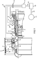
- FIG. 1 schematically illustrates a gas turbine engine 20, in accordance with various embodiments.
- the gas turbine engine 20 is disclosed herein as a two-spool turbofan that generally incorporates a fan section 22, a compressor section 24, a combustor section 26 and a turbine section 28.
- the fan section 22 drives air along a bypass flow path B in a bypass duct defined within a nacelle 15, while the compressor section 24 drives air along a primary or core flow path C for compression and communication into the combustor section 26 and then expansion through the turbine section 28.
- the gas turbine engine 20 generally includes a low speed spool 30 and a high speed spool 32 mounted for rotation about an engine central longitudinal axis A relative to an engine static structure 36 via several bearing systems 38. It should be understood that various bearing systems at various locations may alternatively or additionally be provided and the location of the several bearing systems 38 may be varied as appropriate to the application.
- the low speed spool 30 generally includes an inner shaft 40 that interconnects a fan 42, a low pressure compressor 44 and a low pressure turbine 46.
- the inner shaft 40 is connected to the fan 42 through a speed change mechanism, which, in this gas turbine engine 20, is illustrated as a fan drive gear system 48 configured to drive the fan 42 at a lower speed than that of the low speed spool 30.
- the high speed spool 32 generally includes an outer shaft 50 that interconnects a high pressure compressor 52 and a high pressure turbine 54.
- a combustor 56 is arranged in the gas turbine engine 20 between the high pressure compressor 52 and the high pressure turbine 54.
- a mid-turbine frame 57 of the engine static structure 36 is arranged generally between the high pressure turbine 54 and the low pressure turbine 46 and may include airfoils 59 in the core flow path C for guiding the flow into the low pressure turbine 46.
- the mid-turbine frame 57 further supports the several bearing systems 38 in the turbine section 28.
- the inner shaft 40 and the outer shaft 50 are concentric and rotate via the several bearing systems 38 about the engine central longitudinal axis A, which is collinear with longitudinal axes of the inner shaft 40 and the outer shaft 50.
- the air in the core flow path C is compressed by the low pressure compressor 44 and then the high pressure compressor 52, mixed and burned with fuel in the combustor 56, and then expanded over the high pressure turbine 54 and the low pressure turbine 46.
- the low pressure turbine 46 and the high pressure turbine 54 rotationally drive the respective low speed spool 30 and the high speed spool 32 in response to the expansion.
- each of the positions of the fan section 22, the compressor section 24, the combustor section 26, the turbine section 28, and the fan drive gear system 48 may be varied.
- the fan drive gear system 48 may be located aft of the combustor section 26 or even aft of the turbine section 28, and the fan section 22 may be positioned forward or aft of the location of the fan drive gear system 48.
- the fluid wash system 100 includes a fluid supply 102, a fluid pump 104 and a fluid distribution assembly 106, each of which may be interconnected by a fluid supply conduit 108.
- a plurality of fluid wash lines 110 run from the fluid distribution assembly 106 to a plurality of engine ports 112, each of which typically extends through an engine casing that defines an outer boundary of the core flow path C.
- one or more of the plurality of engine ports 112 may comprise a borescope port 114 (or a plurality of borescope ports extending axially along the engine and circumferentially about the engine) configured to introduce a borescope into the core flow path C or other parts of the gas turbine engine 20 for purposes of inspection or one or more components.
- a nozzle system 120 (which is also configured for predetermined alignment) is connected to each one of the plurality of fluid wash lines 110 and configured for removable attachment with one of the plurality of engine ports 112.
- the nozzle system 120 enables a fluid nozzle (or a spray nozzle) to be releasably secured into an engine port and aligned at a predetermined direction or orientation within, for example, the core flow path C of the gas turbine engine 20.
- This feature ensures the nozzle does not separate from the engine when a pressurized flow of wash liquid is being distributed through the nozzle and into the engine and, further, ensures the pressurized flow of wash liquid is directed at the precise component (or portion of the component) where cleaning is intended to occur.
- a nozzle system 220 is illustrated as part of a fluid wash system, such as, for example, the fluid wash system 100 described above with reference to FIG. 1 .
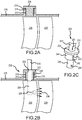
- the nozzle system 220 (illustrated in FIGS. 2B and 2C ) includes a base 222 configured for removable attachment with a borescope port 214.
- the borescope port 214 comprises an aperture 213 that typically extends through a boss 215 that is either integral with (e.g., monolithic) or attached to an engine case 216.
- a plug 224 is illustrated as being disposed within the aperture 213 extending within the boss 215.
- the plug 224 is maintained within the boss 215 using typical methods, including, for example, threads or an external mounting system. Upon removal of the plug 224 from the boss 215, access may be had to the components of the gas turbine engine within the region of the boss 215, including, for example, a plurality of rotor blades 226 disposed downstream of a plurality of stator vanes 228 that are typically disposed in the same axial location as the boss 215.
- the access referred to above is for insertion of a borescope for purposes of inspection.
- the nozzle system 220 may be inserted into the boss 215 and temporarily secured thereto.
- the nozzle system 220 includes the base 222 configured for attachment to the boss 215.
- a nozzle 230 is connected to a wash line 210 (e.g., one of the plurality of fluid wash lines 110 described above with reference to FIG. 1 ) and extends through an aperture 232 that extends through the base 222 and, in various embodiments, the nozzle 230 is held in a fixed position with respect to the base 222, either via a friction fit with the aperture 232 or by an adhesive or similar manner of attachment.
- the nozzle 230 includes an orifice 234, through which a pressurized wash fluid 236 is expelled toward one or more components within the gas turbine engine, including, for example, the plurality of rotor blades 226, during a fluid wash operation.
- the nozzle 230 generally extends radially inward toward the engine central axis A (see FIG. 1 ) and is disposed between a pair of vanes among the plurality of stator vanes 228 when the base 222 is fully positioned within the boss 215.
- the nozzle 230 is either a first spray nozzle or a second spray nozzle, which may be oriented at a first predetermined direction or a second predetermined direction, respectively, with respect to component being washed.
- an alignment mechanism 240 is included within the nozzle system 220 to maintain the nozzle 230 at a fixed orientation during the fluid wash operation.
- the alignment mechanism 240 includes a key 242 that extends outward from a surface 244 of the base 222.
- the key 242 in configured to fit within a slot 246 that is cut into a side of the aperture 232 that extends through the boss 215.
- the key 242 is aligned with the slot 246, thereby preventing the base 222, together with the nozzle 230, from rotating with respect to the boss 215 during a fluid wash operation.
- a mark 251 may be included on a portion of the nozzle system 220 to indicate a direction of the pressurized wash fluid 236 as it leaves the orifice 234.
- the base 222 is securely attached to the boss 215 using, for example, threads or an external mounting system. Secure attachment of the base 222 to the boss 215 prevents the base 222 and the nozzle 230 from becoming loose or being inadvertently removed during the fluid wash operation as well as maintaining the direction of the pressurized wash fluid 236 as it leaves the orifice 234.
- a nozzle system 320 is illustrated as part of a fluid wash system, such as, for example, the fluid wash system 100 described above with reference to FIG. 1 .
- the nozzle system 320 (illustrated in FIGS. 3B and 3C ) includes a base 322 configured for removable attachment with a borescope port 314.
- the borescope port 314 comprises an aperture 313 that typically extends through a boss 315 that is either integral with (e.g., monolithic) or attached to an engine case 316.
- a plug 324 is illustrated as being disposed within the aperture 313 extending within the boss 315.
- the plug 324 is maintained within the boss 315 using a bayonet fixture 350, which, in various embodiments, includes a pin 352 that extends from the boss 315 and a curved slot 354 (see, e.g., the curved slot 356 illustrated in FIG. 3C ) that is cut into the plug 324.
- a bayonet fixture 350 which, in various embodiments, includes a pin 352 that extends from the boss 315 and a curved slot 354 (see, e.g., the curved slot 356 illustrated in FIG. 3C ) that is cut into the plug 324.
- a bayonet fixture 350 which, in various embodiments, includes a pin 352 that extends from the boss 315 and a curved slot 354 (see, e.g., the curved slot 356 illustrated in FIG. 3C ) that is cut into the plug 324.
- the components of the gas turbine engine within the region of the boss 315, including, for example, a plurality of rotor blades
- the nozzle system 320 may be inserted into the boss 315 and temporarily secured thereto.
- the nozzle system 320 includes the base 322 configured for attachment to the boss 315.
- a nozzle 330 is connected to a wash line 310 (e.g., one of the plurality of fluid wash lines 110 described above with reference to FIG. 1 ) and extends through an aperture 332 that extends through the base 322 and, in various embodiments, the nozzle 330 is held in a fixed position with respect to the base 322, either via a friction fit with the aperture 332 or by an adhesive or similar manner of attachment.
- the nozzle 330 includes an orifice 334, through which a pressurized wash fluid 336 is expelled toward one or more components within the gas turbine engine, including, for example, the plurality of rotor blades 326, during a fluid wash operation.
- the nozzle 330 generally extends radially inward toward the engine central axis A (see FIG. 1 ) and is disposed between a pair of vanes among the plurality of stator vanes 328 when the base 322 is fully positioned within the boss 315.
- the nozzle 330 is either a first spray nozzle or a second spray nozzle, which may be oriented at a first predetermined direction or a second predetermined direction, respectively, with respect to component being washed.
- an alignment mechanism 340 is included within the nozzle system 320 to maintain the nozzle 330 at a fixed orientation during the fluid wash operation.
- the alignment mechanism 340 includes the pin 352 that extends from the boss 315 and a curved slot 356 that is cut into the base 322.
- the curved slot 356 is aligned with the pin 352 and the base 322 is rotated such that the pin 352 and the curved slot 356 become locked together, thereby preventing the base 322, together with the nozzle 330, from rotating with respect to the boss 315 during a fluid wash operation.
- a mark 351 may be included on a portion of the nozzle system 320 to indicate a direction of the pressurized wash fluid 336 as it leaves the orifice 334.
- the base 322 is securely attached to the boss 315 using, for example, the curved slot 356 and the pin 352. Secure attachment of the base 322 to the boss 315 prevents the base 322 and the nozzle 330 from becoming loose or being inadvertently removed during the fluid wash operation as well as maintaining the direction of the pressurized wash fluid 336 as it leaves the orifice 334.
- a nozzle system 420 is illustrated as part of a fluid wash system, such as, for example, the fluid wash system 100 described above with reference to FIG. 1 .
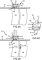
- the nozzle system 420 (illustrated in FIGS. 4B and 4C ) includes a base 422 configured for removable attachment with a borescope port 414.
- the borescope port 414 comprises an aperture 413 that typically extends through a boss 415 that is either integral with (e.g., monolithic) or attached to an engine case 416.
- a plug 424 is illustrated as being disposed within the aperture 413 extending within the boss 415.
- the plug 424 is maintained within the boss 415 using a tine retainer fixture 450, which, in various embodiments, includes a threaded base 458 and a plurality of tines 460 that extend circumferentially about the plug 424 and that are configured to be received within a plurality of slots 462 cut into the boss 415.
- a tine retainer fixture 450 which, in various embodiments, includes a threaded base 458 and a plurality of tines 460 that extend circumferentially about the plug 424 and that are configured to be received within a plurality of slots 462 cut into the boss 415.
- Such plugs may be obtained from Moeller Mfg. Company, LLC, of Wixom Michigan, USA, under the trade name Moeller Click-LocTM Self-Locking Plugs.
- the access referred to above is for insertion of a borescope for purposes of inspection.
- the nozzle system 420 may be inserted into the boss 415 and temporarily secured thereto.
- the nozzle system 420 includes the base 422 configured for attachment to the boss 415.
- a nozzle 430 is connected to a wash line 410 (e.g., one of the plurality of fluid wash lines 110 described above with reference to FIG. 1 ) and extends through an aperture 432 that extends through the base 422 and, in various embodiments, the nozzle 430 is held in a fixed position with respect to the base 422, either via a friction fit with the aperture 432 or by an adhesive or similar manner of attachment.
- the nozzle 430 includes an orifice 434, through which a pressurized wash fluid 436 is expelled toward one or more components within the gas turbine engine, including, for example, the plurality of rotor blades 426, during a fluid wash operation.
- the nozzle 430 generally extends radially inward toward the engine central axis A (see FIG. 1 ) and is disposed between a pair of vanes among the plurality of stator vanes 428 when the base 422 is fully positioned within the boss 415.
- the nozzle 430 is either a first spray nozzle or a second spray nozzle, which may be oriented at a first predetermined direction or a second predetermined direction, respectively, with respect to component being washed.
- an alignment mechanism 440 is included within the nozzle system 420 to maintain the nozzle 430 at a fixed orientation during the fluid wash operation.
- the alignment mechanism 440 includes the tine retainer fixture 450, which, in various embodiments, includes a threaded base 468 and a plurality of tines 470 that extend circumferentially about the base 422 and that are configured to be received within the plurality of slots 462 cut into the boss 415.
- the base 422 When assembling the nozzle system 420 within the boss 415, the base 422 is threaded into the boss 415 until the plurality of tines 470 are engaged with the plurality of slots 462, thereby preventing the base 422, together with the nozzle 430, from rotating with respect to the boss 415 during a fluid wash operation.
- a mark 451 may be included on a portion of the nozzle system 420 to indicate a direction of the pressurized wash fluid 436 as it leaves the orifice 434.
- the base 422 is securely attached to the boss 415 using, for example, a threaded base 468 and corresponding threads cut into the boss 415.
- a nozzle system 520 is illustrated as part of a fluid wash system, such as, for example, the fluid wash system 100 described above with reference to FIG. 1 .
- the nozzle system 520 includes a base 522 configured for removable attachment with a borescope port.
- the base 522 may comprise, for example, the structure associated with any of the base 222, the base 322 and the base 422 described above with reference to FIGS. 2C , 3C and 4C , respectively, including the alignment mechanisms associated therewith.
- a nozzle 530 is connected to a wash line 510 (e.g., one of the plurality of fluid wash lines 110 described above with reference to FIG.
- the nozzle 530 extends through an aperture 532 that extends through the base 522 and, in various embodiments, the nozzle 530 is held in a fixed position with respect to the base 522, either via a friction fit with the aperture 532 or by an adhesive or similar manner of attachment.
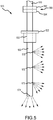
- the nozzle 530 may include a plurality of orifices, including, for example, a first orifice 570 configured to expel pressurized wash fluid in a generally axial direction, a second orifice 572 configured to expel pressurized wash fluid in a generally axial direction, a third orifice 573 configured to expel pressurized wash fluid in a generally axial direction and a generally radial direction (e.g., at a forty-five degree (45°) angle toward an engine central axis A as illustrated in FIG. 1 ), and a fourth orifice 574 configured to expel pressurized wash fluid in a generally radial direction (e.g., toward the engine central axis A).
- a first orifice 570 configured to expel pressurized wash fluid in a generally axial direction
- a second orifice 572 configured to expel pressurized wash fluid in a generally axial direction
- a third orifice 573 configured to expel pressurized wash fluid in a generally
- a predetermined direction of the pressurized flow of wash fluid may be within a range of about zero degrees (or an axial direction) to about ninety degrees (or a radial inward direction); and in various embodiments, the predetermined direction of the pressurized flow of wash fluid may be within a range of about thirty degrees to about sixty degrees.
- Such a configuration permits washing a relatively large area of the engine as opposed to configurations having a single orifice.
- the disclosure contemplates orienting the orifices in any direction, including both generally forward and generally aft directions, circumferential directions (e.g., to wash stator vanes), as well as radially inward and radially outward directions, or combinations of the foregoing directions.
- a coupling mechanism 580 is included to enable quick attachment and release of the nozzle system 520 to the wash line 510.
- the coupling mechanism 580 may comprise a quick release coupler that includes a first end 582 connected to the wash line 510 and a second end 584 connected to the nozzle 530 extending through the base 522.
- the coupling mechanism 580 enables, among other things, for the nozzle system 520 to be separated from the wash line 510 when not in use.
- the coupling mechanism 580 also enables the nozzle system 520 to be securely attached to a boss or other borescope port first, and then connected to the wash line 510 once securely attached.
- a method 600 of washing a gas turbine engine having a borescope hole providing access to a component within a core flow path is described as having at least the following steps.
- a first step 602 includes removing a plug from the borescope hole.
- a second step 604 includes inserting a spray nozzle into the borescope hole.
- a third step 606 includes attaching the spray nozzle to the borescope hole using an attachment mechanism, the attachment mechanism including an alignment mechanism configured to orient the spray nozzle and direct a pressurized flow of wash liquid in a predetermined direction toward the component.
- the attachment mechanism includes a base and the alignment mechanism includes a key extending from the base and configured for engagement with a slot that is cut into a boss configured to receive the base.
- the attachment mechanism includes a base and the alignment mechanism includes a slot that is cut into the base and configured to engage a pin extending from a boss configured to receive the base.
- the attachment mechanism includes a base and the alignment mechanism includes a plurality of tines extending circumferentially about the base and configured to engage a plurality of slots that are cut into a boss configured to receive the base.
- references to "one embodiment,” “an embodiment,” “various embodiments,” etc. indicate that the embodiment described may include a particular feature, structure, or characteristic, but every embodiment may not necessarily include the particular feature, structure, or characteristic. Moreover, such phrases are not necessarily referring to the same embodiment. Further, when a particular feature, structure, or characteristic is described in connection with an embodiment, it is submitted that it is within the knowledge of one skilled in the art to affect such feature, structure, or characteristic in connection with other embodiments whether or not explicitly described. After reading the description, it will be apparent to one skilled in the relevant art(s) how to implement the disclosure in alternative embodiments.
- Numbers, percentages, or other values stated herein are intended to include that value, and also other values that are about or approximately equal to the stated value, as would be appreciated by one of ordinary skill in the art encompassed by various embodiments of the present disclosure.
- a stated value should therefore be interpreted broadly enough to encompass values that are at least close enough to the stated value to perform a desired function or achieve a desired result.
- the stated values include at least the variation to be expected in a suitable industrial process, and may include values that are within 10%, within 5%, within 1%, within 0.1%, or within 0.01% of a stated value.
- the terms “substantially,” “about” or “approximately” as used herein represent an amount close to the stated amount that still performs a desired function or achieves a desired result.
- the term “substantially,” “about” or “approximately” may refer to an amount that is within 10% of, within 5% of, within 1% of, within 0.1% of, and within 0.01% of a stated amount or value
Landscapes
- Engineering & Computer Science (AREA)
- Mechanical Engineering (AREA)
- General Engineering & Computer Science (AREA)
- Turbine Rotor Nozzle Sealing (AREA)
- Cleaning By Liquid Or Steam (AREA)
Abstract
Description
- This application is a non-provisional application claiming priority to U.S. Prov. Appl.
62/976,825 - The present disclosure relates to gas turbine engines and, more particularly, to apparatus and methods used to fluid wash gas turbine engines.
- Deposits or debris formed on the various rotor blades or stator vanes within the compressor and the turbine sections in a gas turbine engine impair the aerodynamic condition and dynamics of the engine, thereby affecting efficiency. Similar buildups of deposits or debris on other components within a gas turbine engine, such as, for example, struts, flow path surfaces and combustor panels, may also impair the affect the efficiency of the engine during operation. Accordingly, at various maintenance intervals, it is desirable to wash the engine in order to reduce build-up on the blades or vanes or other components within a gas turbine engine. Accessing various blade or vane stages may prove difficult from the engine inlet or exhaust, thereby often requiring washing the engine either by removing other engine equipment, such as bleed valves, or by using dedicated borescope or wash ports to provide access to the engine interior. Conventional approaches may be time consuming or difficult to provide access for cleaning purposes, which results in poor cleaning.
- A fluid wash system for a gas turbine engine is disclosed, the gas turbine engine defining an axial direction and comprising a borescope port that provides access to a component within a core flow path of the gas turbine engine. In various embodiments, the fluid wash system includes a wash line fluidly connected to a pump configured to provide a pressurized flow of wash liquid; a spray nozzle connected to the wash line and configured for extending into the borescope port to provide the pressurized flow of wash liquid to the component within the core flow path; and an attachment mechanism configured to releasably mount the spray nozzle to the borescope port, the attachment mechanism including an alignment mechanism configured to orient the spray nozzle and direct the pressurized flow of wash liquid in a predetermined direction toward the component.
- In various embodiments, the attachment mechanism includes a base and the alignment mechanism includes a key extending from the base and configured for engagement with a slot that is cut into a boss configured to receive the base. In various embodiments, the spray nozzle includes an orifice configured to expel the pressurized flow of wash liquid toward the component. In various embodiments, the predetermined direction is within a range of about zero degrees to about ninety degrees in a radial inward direction with respect to the axial direction. In various embodiments, the spray nozzle is a first spray nozzle configured for mounting to the attachment mechanism and configured for orientation with respect to the component at a first predetermined direction and, in various embodiments, the fluid wash system further includes a second spray nozzle configured for mounting to the attachment mechanism and configured for orientation with respect to the component at a second predetermined direction. In various embodiments, the spray nozzle includes a plurality of orifices configured to expel the pressurized flow of wash liquid toward the component.
- In various embodiments, the attachment mechanism includes a base and the alignment mechanism includes a slot that is cut into the base and configured to engage a pin extending from a boss configured to receive the base. In various embodiments, the spray nozzle includes an orifice configured to expel the pressurized flow of wash liquid toward the component in a direction within a range of about zero degrees to about ninety degrees in a radial inward direction with respect to the axial direction and wherein the spray nozzle is rotatable with respect to the base. In various embodiments, the spray nozzle includes a plurality of orifices configured to expel the pressurized flow of wash liquid toward the component.
- In various embodiments, the attachment mechanism includes a base and the alignment mechanism includes a plurality of tines extending circumferentially about the base and configured to engage a plurality of slots that are cut into a boss configured to receive the base. In various embodiments, the spray nozzle includes an orifice configured to expel the pressurized flow of wash liquid toward the component in a direction within a range of about zero degrees to about ninety degrees in a radial inward direction with respect to the axial direction. In various embodiments, the spray nozzle includes a plurality of orifices configured to expel the pressurized flow of wash liquid toward the component.
- A fluid wash system for a gas turbine engine is disclosed, the gas turbine engine defining an axial direction and comprising a plurality of borescope ports. In various embodiments, the fluid wash system includes a pump configured to output a pressurized flow of wash liquid; a nozzle distribution assembly fluidly connected to the pump for receiving the pressurized flow of wash liquid; a plurality of wash lines fluidly connected to the nozzle distribution assembly; and a plurality of spray nozzles, each of the plurality of spray nozzles connected by an attachment mechanism to a respective one of the plurality of wash lines and configured for extending at least partially into or through one of the plurality of borescope ports of the gas turbine engine for providing a portion of the pressurized flow of wash liquid to a component within the gas turbine engine, the attachment mechanism including an alignment mechanism.
- In various embodiments, the attachment mechanism includes a base and the alignment mechanism includes a key extending from the base and configured for engagement with a slot that is cut into a boss configured to receive the base. In various embodiments, the attachment mechanism includes a base and the alignment mechanism includes a slot that is cut into the base and configured to engage a pin extending from a boss configured to receive the base. In various embodiments, the attachment mechanism includes a base and the alignment mechanism includes a plurality of tines extending circumferentially about the base and configured to engage a plurality of slots that are cut into a boss configured to receive the base.
- A method of washing a gas turbine engine having a borescope hole providing access to a component within a core flow path is disclosed. In various embodiments, the method includes the steps of removing a plug from the borescope hole; inserting a spray nozzle into the borescope hole; and attaching the spray nozzle to the borescope hole using an attachment mechanism, the attachment mechanism including an alignment mechanism configured to orient the spray nozzle and direct a pressurized flow of wash liquid in a predetermined direction toward the component.
- In various embodiments, the attachment mechanism includes a base and the alignment mechanism includes a key extending from the base and configured for engagement with a slot that is cut into a boss configured to receive the base. In various embodiments, the attachment mechanism includes a base and the alignment mechanism includes a slot that is cut into the base and configured to engage a pin extending from a boss configured to receive the base. In various embodiments, the attachment mechanism includes a base and the alignment mechanism includes a plurality of tines extending circumferentially about the base and configured to engage a plurality of slots that are cut into a boss configured to receive the base.
- The forgoing features and elements may be combined in any combination, without exclusivity, unless expressly indicated herein otherwise. These features and elements as well as the operation of the disclosed embodiments will become more apparent in light of the following description and accompanying drawings.
- The subject matter of the present disclosure is particularly pointed out and distinctly claimed in the concluding portion of the specification. A more complete understanding of the present disclosure, however, may best be obtained by referring to the following detailed description and claims in connection with the following drawings. While the drawings illustrate various embodiments employing the principles described herein, the drawings do not limit the scope of the claims.
-
FIG. 1 is a cross sectional schematic view of a gas turbine engine, in accordance with various embodiments; -
FIGS. 2A, 2B and 2C illustrate various aspects of a fluid wash system for a gas turbine engine, in accordance with various embodiments; -
FIGS. 3A, 3B and 3C illustrate various aspects of a fluid wash system for a gas turbine engine, in accordance with various embodiments; -
FIGS. 4A, 4B and 4C illustrate various aspects of a fluid wash system for a gas turbine engine, in accordance with various embodiments; -
FIG. 5 illustrates a nozzle system as part of a fluid wash system, in accordance with various embodiments; and -
FIG. 6 describes various method steps involved in fluid washing a gas turbine engine, in accordance with various embodiments. - The following detailed description of various embodiments herein makes reference to the accompanying drawings, which show various embodiments by way of illustration. While these various embodiments are described in sufficient detail to enable those skilled in the art to practice the disclosure, it should be understood that other embodiments may be realized and that changes may be made without departing from the scope of the disclosure. Thus, the detailed description herein is presented for purposes of illustration only and not of limitation. Furthermore, any reference to singular includes plural embodiments, and any reference to more than one component or step may include a singular embodiment or step. Also, any reference to attached, fixed, connected, or the like may include permanent, removable, temporary, partial, full or any other possible attachment option. Additionally, any reference to without contact (or similar phrases) may also include reduced contact or minimal contact. It should also be understood that unless specifically stated otherwise, references to "a," "an" or "the" may include one or more than one and that reference to an item in the singular may also include the item in the plural. Further, all ranges may include upper and lower values and all ranges and ratio limits disclosed herein may be combined.
- Referring now to the drawings,
FIG. 1 schematically illustrates agas turbine engine 20, in accordance with various embodiments. Thegas turbine engine 20 is disclosed herein as a two-spool turbofan that generally incorporates afan section 22, acompressor section 24, acombustor section 26 and aturbine section 28. Thefan section 22 drives air along a bypass flow path B in a bypass duct defined within anacelle 15, while thecompressor section 24 drives air along a primary or core flow path C for compression and communication into thecombustor section 26 and then expansion through theturbine section 28. Although depicted as a two-spool turbofan gas turbine engine in the disclosed non-limiting embodiment, it will be understood that the concepts described herein are not limited to use with two-spool turbofans, as the teachings may be applied to other types of gas turbine engines, including, for example, architectures having three or more spools or only a single spool. - The
gas turbine engine 20 generally includes alow speed spool 30 and ahigh speed spool 32 mounted for rotation about an engine central longitudinal axis A relative to an enginestatic structure 36 viaseveral bearing systems 38. It should be understood that various bearing systems at various locations may alternatively or additionally be provided and the location of theseveral bearing systems 38 may be varied as appropriate to the application. Thelow speed spool 30 generally includes aninner shaft 40 that interconnects afan 42, alow pressure compressor 44 and alow pressure turbine 46. Theinner shaft 40 is connected to thefan 42 through a speed change mechanism, which, in thisgas turbine engine 20, is illustrated as a fandrive gear system 48 configured to drive thefan 42 at a lower speed than that of thelow speed spool 30. Thehigh speed spool 32 generally includes anouter shaft 50 that interconnects ahigh pressure compressor 52 and ahigh pressure turbine 54. Acombustor 56 is arranged in thegas turbine engine 20 between thehigh pressure compressor 52 and thehigh pressure turbine 54. Amid-turbine frame 57 of the enginestatic structure 36 is arranged generally between thehigh pressure turbine 54 and thelow pressure turbine 46 and may includeairfoils 59 in the core flow path C for guiding the flow into thelow pressure turbine 46. Themid-turbine frame 57 further supports theseveral bearing systems 38 in theturbine section 28. Theinner shaft 40 and theouter shaft 50 are concentric and rotate via theseveral bearing systems 38 about the engine central longitudinal axis A, which is collinear with longitudinal axes of theinner shaft 40 and theouter shaft 50. - The air in the core flow path C is compressed by the
low pressure compressor 44 and then thehigh pressure compressor 52, mixed and burned with fuel in thecombustor 56, and then expanded over thehigh pressure turbine 54 and thelow pressure turbine 46. Thelow pressure turbine 46 and thehigh pressure turbine 54 rotationally drive the respectivelow speed spool 30 and thehigh speed spool 32 in response to the expansion. It will be appreciated that each of the positions of thefan section 22, thecompressor section 24, thecombustor section 26, theturbine section 28, and the fandrive gear system 48 may be varied. For example, the fandrive gear system 48 may be located aft of thecombustor section 26 or even aft of theturbine section 28, and thefan section 22 may be positioned forward or aft of the location of the fandrive gear system 48. - Still referring to
FIG. 1 , afluid wash system 100 is illustrated, in accordance with various embodiments. Thefluid wash system 100 includes afluid supply 102, afluid pump 104 and afluid distribution assembly 106, each of which may be interconnected by afluid supply conduit 108. A plurality offluid wash lines 110 run from thefluid distribution assembly 106 to a plurality ofengine ports 112, each of which typically extends through an engine casing that defines an outer boundary of the core flow path C. In various embodiments, for example, one or more of the plurality ofengine ports 112 may comprise a borescope port 114 (or a plurality of borescope ports extending axially along the engine and circumferentially about the engine) configured to introduce a borescope into the core flow path C or other parts of thegas turbine engine 20 for purposes of inspection or one or more components. As described further below, a nozzle system 120 (which is also configured for predetermined alignment) is connected to each one of the plurality offluid wash lines 110 and configured for removable attachment with one of the plurality ofengine ports 112. As will become further apparent from the description below, thenozzle system 120 enables a fluid nozzle (or a spray nozzle) to be releasably secured into an engine port and aligned at a predetermined direction or orientation within, for example, the core flow path C of thegas turbine engine 20. This feature ensures the nozzle does not separate from the engine when a pressurized flow of wash liquid is being distributed through the nozzle and into the engine and, further, ensures the pressurized flow of wash liquid is directed at the precise component (or portion of the component) where cleaning is intended to occur. - Referring now to
FIGS. 2A, 2B and 2C , anozzle system 220 is illustrated as part of a fluid wash system, such as, for example, thefluid wash system 100 described above with reference toFIG. 1 . The nozzle system 220 (illustrated inFIGS. 2B and 2C ) includes a base 222 configured for removable attachment with aborescope port 214. As illustrated, in various embodiments, theborescope port 214 comprises anaperture 213 that typically extends through aboss 215 that is either integral with (e.g., monolithic) or attached to anengine case 216. Referring toFIG. 2A , aplug 224 is illustrated as being disposed within theaperture 213 extending within theboss 215. Theplug 224 is maintained within theboss 215 using typical methods, including, for example, threads or an external mounting system. Upon removal of theplug 224 from theboss 215, access may be had to the components of the gas turbine engine within the region of theboss 215, including, for example, a plurality ofrotor blades 226 disposed downstream of a plurality ofstator vanes 228 that are typically disposed in the same axial location as theboss 215. In various embodiments, the access referred to above is for insertion of a borescope for purposes of inspection. - Referring more particularly to
FIGS. 2B and 2C , upon removal of theplug 224 from theboss 215, thenozzle system 220 may be inserted into theboss 215 and temporarily secured thereto. As illustrated, thenozzle system 220 includes the base 222 configured for attachment to theboss 215. Anozzle 230 is connected to a wash line 210 (e.g., one of the plurality offluid wash lines 110 described above with reference toFIG. 1 ) and extends through anaperture 232 that extends through thebase 222 and, in various embodiments, thenozzle 230 is held in a fixed position with respect to thebase 222, either via a friction fit with theaperture 232 or by an adhesive or similar manner of attachment. Thenozzle 230 includes anorifice 234, through which apressurized wash fluid 236 is expelled toward one or more components within the gas turbine engine, including, for example, the plurality ofrotor blades 226, during a fluid wash operation. As illustrated inFIG. 2B , thenozzle 230 generally extends radially inward toward the engine central axis A (seeFIG. 1 ) and is disposed between a pair of vanes among the plurality ofstator vanes 228 when thebase 222 is fully positioned within theboss 215. In various embodiments, thenozzle 230 is either a first spray nozzle or a second spray nozzle, which may be oriented at a first predetermined direction or a second predetermined direction, respectively, with respect to component being washed. - Still referring particularly to
FIGS. 2B and 2C , analignment mechanism 240 is included within thenozzle system 220 to maintain thenozzle 230 at a fixed orientation during the fluid wash operation. In various embodiments, thealignment mechanism 240 includes a key 242 that extends outward from asurface 244 of thebase 222. The key 242 in configured to fit within aslot 246 that is cut into a side of theaperture 232 that extends through theboss 215. When assembling thenozzle system 220 within theboss 215, the key 242 is aligned with theslot 246, thereby preventing thebase 222, together with thenozzle 230, from rotating with respect to theboss 215 during a fluid wash operation. In various embodiments, amark 251 may be included on a portion of thenozzle system 220 to indicate a direction of thepressurized wash fluid 236 as it leaves theorifice 234. In various embodiments, thebase 222 is securely attached to theboss 215 using, for example, threads or an external mounting system. Secure attachment of the base 222 to theboss 215 prevents thebase 222 and thenozzle 230 from becoming loose or being inadvertently removed during the fluid wash operation as well as maintaining the direction of thepressurized wash fluid 236 as it leaves theorifice 234. In addition, as the direction of thepressurized wash fluid 236 is generally fixed with respect to thebase 222, different nozzle systems exhibiting different directions of the pressurized wash fluid with respect to the base 222 (or with respect to the boss 215) may be employed to achieve more complete washing of all components within the vicinity of theboss 215 during the fluid wash operation. As described in more detail below, various other alignment mechanisms are contemplated as being within the scope of the disclosure. - Referring now to
FIGS. 3A, 3B and 3C , anozzle system 320 is illustrated as part of a fluid wash system, such as, for example, thefluid wash system 100 described above with reference toFIG. 1 . The nozzle system 320 (illustrated inFIGS. 3B and 3C ) includes a base 322 configured for removable attachment with aborescope port 314. As illustrated, in various embodiments, theborescope port 314 comprises anaperture 313 that typically extends through aboss 315 that is either integral with (e.g., monolithic) or attached to anengine case 316. Referring toFIG. 3A , aplug 324 is illustrated as being disposed within theaperture 313 extending within theboss 315. Theplug 324 is maintained within theboss 315 using abayonet fixture 350, which, in various embodiments, includes apin 352 that extends from theboss 315 and a curved slot 354 (see, e.g., thecurved slot 356 illustrated inFIG. 3C ) that is cut into theplug 324. Upon removal of theplug 324 from theboss 315 by twisting the plug with respect to thepin 352, access may be had to the components of the gas turbine engine within the region of theboss 315, including, for example, a plurality ofrotor blades 326 disposed downstream of a plurality ofstator vanes 328 that are typically disposed in the same axial location as theboss 315. In various embodiments, the access referred to above is for insertion of a borescope for purposes of inspection. - Referring more particularly to
FIGS. 3B and 3C , upon removal of theplug 324 from theboss 315, thenozzle system 320 may be inserted into theboss 315 and temporarily secured thereto. As illustrated, thenozzle system 320 includes the base 322 configured for attachment to theboss 315. Anozzle 330 is connected to a wash line 310 (e.g., one of the plurality offluid wash lines 110 described above with reference toFIG. 1 ) and extends through anaperture 332 that extends through thebase 322 and, in various embodiments, thenozzle 330 is held in a fixed position with respect to thebase 322, either via a friction fit with theaperture 332 or by an adhesive or similar manner of attachment. Thenozzle 330 includes anorifice 334, through which apressurized wash fluid 336 is expelled toward one or more components within the gas turbine engine, including, for example, the plurality ofrotor blades 326, during a fluid wash operation. As illustrated inFIG. 3B , thenozzle 330 generally extends radially inward toward the engine central axis A (seeFIG. 1 ) and is disposed between a pair of vanes among the plurality ofstator vanes 328 when thebase 322 is fully positioned within theboss 315. In various embodiments, thenozzle 330 is either a first spray nozzle or a second spray nozzle, which may be oriented at a first predetermined direction or a second predetermined direction, respectively, with respect to component being washed. - Still referring particularly to
FIGS. 3B and 3C , an alignment mechanism 340 is included within thenozzle system 320 to maintain thenozzle 330 at a fixed orientation during the fluid wash operation. In various embodiments, the alignment mechanism 340 includes thepin 352 that extends from theboss 315 and acurved slot 356 that is cut into thebase 322. When assembling thenozzle system 320 within theboss 315, thecurved slot 356 is aligned with thepin 352 and thebase 322 is rotated such that thepin 352 and thecurved slot 356 become locked together, thereby preventing thebase 322, together with thenozzle 330, from rotating with respect to theboss 315 during a fluid wash operation. In various embodiments, amark 351 may be included on a portion of thenozzle system 320 to indicate a direction of thepressurized wash fluid 336 as it leaves theorifice 334. In various embodiments, thebase 322 is securely attached to theboss 315 using, for example, thecurved slot 356 and thepin 352. Secure attachment of the base 322 to theboss 315 prevents thebase 322 and thenozzle 330 from becoming loose or being inadvertently removed during the fluid wash operation as well as maintaining the direction of thepressurized wash fluid 336 as it leaves theorifice 334. In addition, as the direction of thepressurized wash fluid 336 is generally fixed with respect to thebase 322, different nozzle systems exhibiting different directions of the pressurized wash fluid with respect to the base 322 (or with respect to the boss 315) may be employed to achieve more complete washing of all components within the vicinity of theboss 315 during the fluid wash operation. - Referring now to
FIGS. 4A, 4B and 4C , anozzle system 420 is illustrated as part of a fluid wash system, such as, for example, thefluid wash system 100 described above with reference toFIG. 1 . The nozzle system 420 (illustrated inFIGS. 4B and 4C ) includes a base 422 configured for removable attachment with aborescope port 414. As illustrated, in various embodiments, theborescope port 414 comprises anaperture 413 that typically extends through aboss 415 that is either integral with (e.g., monolithic) or attached to anengine case 416. Referring toFIG. 4A , aplug 424 is illustrated as being disposed within theaperture 413 extending within theboss 415. Theplug 424 is maintained within theboss 415 using atine retainer fixture 450, which, in various embodiments, includes a threadedbase 458 and a plurality oftines 460 that extend circumferentially about theplug 424 and that are configured to be received within a plurality ofslots 462 cut into theboss 415. Such plugs may be obtained from Moeller Mfg. Company, LLC, of Wixom Michigan, USA, under the trade name Moeller Click-Loc™ Self-Locking Plugs. Upon removal of theplug 424 from theboss 415 by twisting theplug 424 with respect to theboss 415, access may be had to the components of the gas turbine engine within the region of theboss 415, including, for example, a plurality ofrotor blades 426 disposed downstream of a plurality ofstator vanes 428 that are typically disposed in the same axial location as theboss 415. In various embodiments, the access referred to above is for insertion of a borescope for purposes of inspection. - Referring more particularly to
FIGS. 4B and 4C , upon removal of theplug 424 from theboss 415, thenozzle system 420 may be inserted into theboss 415 and temporarily secured thereto. As illustrated, thenozzle system 420 includes the base 422 configured for attachment to theboss 415. Anozzle 430 is connected to a wash line 410 (e.g., one of the plurality offluid wash lines 110 described above with reference toFIG. 1 ) and extends through anaperture 432 that extends through thebase 422 and, in various embodiments, thenozzle 430 is held in a fixed position with respect to thebase 422, either via a friction fit with theaperture 432 or by an adhesive or similar manner of attachment. Thenozzle 430 includes anorifice 434, through which apressurized wash fluid 436 is expelled toward one or more components within the gas turbine engine, including, for example, the plurality ofrotor blades 426, during a fluid wash operation. As illustrated inFIG. 4B , thenozzle 430 generally extends radially inward toward the engine central axis A (seeFIG. 1 ) and is disposed between a pair of vanes among the plurality ofstator vanes 428 when thebase 422 is fully positioned within theboss 415. In various embodiments, thenozzle 430 is either a first spray nozzle or a second spray nozzle, which may be oriented at a first predetermined direction or a second predetermined direction, respectively, with respect to component being washed. - Still referring particularly to
FIGS. 4B and 4C , an alignment mechanism 440 is included within thenozzle system 420 to maintain thenozzle 430 at a fixed orientation during the fluid wash operation. In various embodiments, the alignment mechanism 440 includes thetine retainer fixture 450, which, in various embodiments, includes a threadedbase 468 and a plurality oftines 470 that extend circumferentially about thebase 422 and that are configured to be received within the plurality ofslots 462 cut into theboss 415. When assembling thenozzle system 420 within theboss 415, thebase 422 is threaded into theboss 415 until the plurality oftines 470 are engaged with the plurality ofslots 462, thereby preventing thebase 422, together with thenozzle 430, from rotating with respect to theboss 415 during a fluid wash operation. In various embodiments, amark 451 may be included on a portion of thenozzle system 420 to indicate a direction of thepressurized wash fluid 436 as it leaves theorifice 434. In various embodiments, thebase 422 is securely attached to theboss 415 using, for example, a threadedbase 468 and corresponding threads cut into theboss 415. Secure attachment of the base 422 to theboss 415 prevents thebase 422 and thenozzle 430 from becoming loose or being inadvertently removed during the fluid wash operation as well as maintaining the direction of thepressurized wash fluid 436 as it leaves theorifice 434. An added benefit of thenozzle system 420 is once the plurality oftines 470 is engaged with the plurality ofslots 462, thenozzle 430 may still be rotated with respect to thebase 422, thereby permitting adjustment of the direction of thepressurized wash fluid 436 during the fluid wash operation. - Referring now to
FIG. 5 , anozzle system 520 is illustrated as part of a fluid wash system, such as, for example, thefluid wash system 100 described above with reference toFIG. 1 . Thenozzle system 520 includes a base 522 configured for removable attachment with a borescope port. In various embodiments, thebase 522 may comprise, for example, the structure associated with any of thebase 222, thebase 322 and the base 422 described above with reference toFIGS. 2C ,3C and4C , respectively, including the alignment mechanisms associated therewith. Anozzle 530 is connected to a wash line 510 (e.g., one of the plurality offluid wash lines 110 described above with reference toFIG. 1 ) and extends through anaperture 532 that extends through thebase 522 and, in various embodiments, thenozzle 530 is held in a fixed position with respect to thebase 522, either via a friction fit with theaperture 532 or by an adhesive or similar manner of attachment. Thenozzle 530 may include a plurality of orifices, including, for example, afirst orifice 570 configured to expel pressurized wash fluid in a generally axial direction, asecond orifice 572 configured to expel pressurized wash fluid in a generally axial direction, athird orifice 573 configured to expel pressurized wash fluid in a generally axial direction and a generally radial direction (e.g., at a forty-five degree (45°) angle toward an engine central axis A as illustrated inFIG. 1 ), and afourth orifice 574 configured to expel pressurized wash fluid in a generally radial direction (e.g., toward the engine central axis A). Broadly speaking, in various embodiments, a predetermined direction of the pressurized flow of wash fluid may be within a range of about zero degrees (or an axial direction) to about ninety degrees (or a radial inward direction); and in various embodiments, the predetermined direction of the pressurized flow of wash fluid may be within a range of about thirty degrees to about sixty degrees. Such a configuration permits washing a relatively large area of the engine as opposed to configurations having a single orifice. Further, while the orifices just described are oriented in a generally aft or radially inward direction, the disclosure contemplates orienting the orifices in any direction, including both generally forward and generally aft directions, circumferential directions (e.g., to wash stator vanes), as well as radially inward and radially outward directions, or combinations of the foregoing directions. In addition, in various embodiments, acoupling mechanism 580 is included to enable quick attachment and release of thenozzle system 520 to thewash line 510. In various embodiments, thecoupling mechanism 580 may comprise a quick release coupler that includes afirst end 582 connected to thewash line 510 and asecond end 584 connected to thenozzle 530 extending through thebase 522. Thecoupling mechanism 580 enables, among other things, for thenozzle system 520 to be separated from thewash line 510 when not in use. Thecoupling mechanism 580 also enables thenozzle system 520 to be securely attached to a boss or other borescope port first, and then connected to thewash line 510 once securely attached. - Referring now to
FIG. 6 , amethod 600 of washing a gas turbine engine having a borescope hole providing access to a component within a core flow path is described as having at least the following steps. Afirst step 602 includes removing a plug from the borescope hole. Asecond step 604 includes inserting a spray nozzle into the borescope hole. Athird step 606 includes attaching the spray nozzle to the borescope hole using an attachment mechanism, the attachment mechanism including an alignment mechanism configured to orient the spray nozzle and direct a pressurized flow of wash liquid in a predetermined direction toward the component. In various embodiments, the attachment mechanism includes a base and the alignment mechanism includes a key extending from the base and configured for engagement with a slot that is cut into a boss configured to receive the base. In various embodiments, the attachment mechanism includes a base and the alignment mechanism includes a slot that is cut into the base and configured to engage a pin extending from a boss configured to receive the base. In various embodiments, the attachment mechanism includes a base and the alignment mechanism includes a plurality of tines extending circumferentially about the base and configured to engage a plurality of slots that are cut into a boss configured to receive the base. - Benefits, other advantages, and solutions to problems have been described herein with regard to specific embodiments. Furthermore, the connecting lines shown in the various figures contained herein are intended to represent exemplary functional relationships and/or physical couplings between the various elements. It should be noted that many alternative or additional functional relationships or physical connections may be present in a practical system. However, the benefits, advantages, solutions to problems, and any elements that may cause any benefit, advantage, or solution to occur or become more pronounced are not to be construed as critical, required, or essential features or elements of the disclosure. The scope of the disclosure is accordingly to be limited by nothing other than the appended claims, in which reference to an element in the singular is not intended to mean "one and only one" unless explicitly so stated, but rather "one or more." Moreover, where a phrase similar to "at least one of A, B, or C" is used in the claims, it is intended that the phrase be interpreted to mean that A alone may be present in an embodiment, B alone may be present in an embodiment, C alone may be present in an embodiment, or that any combination of the elements A, B and C may be present in a single embodiment; for example, A and B, A and C, B and C, or A and B and C. Different cross-hatching is used throughout the figures to denote different parts but not necessarily to denote the same or different materials.
- Systems, methods and apparatus are provided herein. In the detailed description herein, references to "one embodiment," "an embodiment," "various embodiments," etc., indicate that the embodiment described may include a particular feature, structure, or characteristic, but every embodiment may not necessarily include the particular feature, structure, or characteristic. Moreover, such phrases are not necessarily referring to the same embodiment. Further, when a particular feature, structure, or characteristic is described in connection with an embodiment, it is submitted that it is within the knowledge of one skilled in the art to affect such feature, structure, or characteristic in connection with other embodiments whether or not explicitly described. After reading the description, it will be apparent to one skilled in the relevant art(s) how to implement the disclosure in alternative embodiments.
- Numbers, percentages, or other values stated herein are intended to include that value, and also other values that are about or approximately equal to the stated value, as would be appreciated by one of ordinary skill in the art encompassed by various embodiments of the present disclosure. A stated value should therefore be interpreted broadly enough to encompass values that are at least close enough to the stated value to perform a desired function or achieve a desired result. The stated values include at least the variation to be expected in a suitable industrial process, and may include values that are within 10%, within 5%, within 1%, within 0.1%, or within 0.01% of a stated value. Additionally, the terms "substantially," "about" or "approximately" as used herein represent an amount close to the stated amount that still performs a desired function or achieves a desired result. For example, the term "substantially," "about" or "approximately" may refer to an amount that is within 10% of, within 5% of, within 1% of, within 0.1% of, and within 0.01% of a stated amount or value.
- Furthermore, no element, component, or method step in the present disclosure is intended to be dedicated to the public regardless of whether the element, component, or method step is explicitly recited in the claims. No claim element herein is to be construed under the provisions of 35 U.S.C. 112(f) unless the element is expressly recited using the phrase "means for." As used herein, the terms "comprises," "comprising," or any other variation thereof, are intended to cover a non-exclusive inclusion, such that a process, method, article, or apparatus that comprises a list of elements does not include only those elements but may include other elements not expressly listed or inherent to such process, method, article, or apparatus.
- Finally, it should be understood that any of the above described concepts can be used alone or in combination with any or all of the other above described concepts. Although various embodiments have been disclosed and described, one of ordinary skill in this art would recognize that certain modifications would come within the scope of this disclosure. Accordingly, the description is not intended to be exhaustive or to limit the principles described or illustrated herein to any precise form. Many modifications and variations are possible in light of the above teaching.
Claims (15)
- A fluid wash system for a gas turbine engine, the gas turbine engine defining an axial direction and comprising a borescope port that provides access to a component within a core flow path of the gas turbine engine, the fluid wash system comprising:a wash line fluidly connected to a pump configured to provide a pressurized flow of wash liquid;a spray nozzle connected to the wash line and configured for extending into the borescope port to provide the pressurized flow of wash liquid to the component within the core flow path; andan attachment mechanism configured to releasably mount the spray nozzle to the borescope port, the attachment mechanism including an alignment mechanism configured to orient the spray nozzle and direct the pressurized flow of wash liquid in a predetermined direction toward the component.
- A fluid wash system for a gas turbine engine, the gas turbine engine defining an axial direction and comprising a plurality of borescope ports, the fluid wash system comprising:a pump configured to output a pressurized flow of wash liquid;a nozzle distribution assembly fluidly connected to the pump for receiving the pressurized flow of wash liquid;a plurality of wash lines fluidly connected to the nozzle distribution assembly; anda plurality of spray nozzles, each of the plurality of spray nozzles connected by an attachment mechanism to a respective one of the plurality of wash lines and configured for extending at least partially into or through one of the plurality of borescope ports of the gas turbine engine for providing a portion of the pressurized flow of wash liquid to a component within the gas turbine engine, the attachment mechanism including an alignment mechanism.
- The fluid wash system of claim 1 or 2, wherein the attachment mechanism includes a base and the alignment mechanism includes a key extending from the base and configured for engagement with a slot that is cut into a boss configured to receive the base.
- The fluid wash system of claim 3 when dependent on claim 1, wherein the spray nozzle includes an orifice configured to expel the pressurized flow of wash liquid toward the component.
- The fluid wash system of claim 4, wherein the predetermined direction is within a range of about zero degrees to about ninety degrees in a radial inward direction with respect to the axial direction.
- The fluid wash system of claim 4 or 5, wherein the spray nozzle is a first spray nozzle configured for mounting to the attachment mechanism and configured for orientation with respect to the component at a first predetermined direction and wherein the fluid wash system further comprises a second spray nozzle configured for mounting to the attachment mechanism and configured for orientation with respect to the component at a second predetermined direction.
- The fluid wash system of claim 1 or 2, wherein the attachment mechanism includes a base and the alignment mechanism includes a slot that is cut into the base and configured to engage a pin extending from a boss configured to receive the base.
- The fluid wash system of claim 7 when dependent on claim 1, wherein the spray nozzle includes an orifice configured to expel the pressurized flow of wash liquid toward the component in a direction within a range of about zero degrees to about ninety degrees in a radial inward direction with respect to the axial direction.
- The fluid wash system of claim 1 or 2, wherein the attachment mechanism includes a base and the alignment mechanism includes a plurality of tines extending circumferentially about the base and configured to engage a plurality of slots that are cut into a boss configured to receive the base.
- The fluid wash system of claim 9 when dependent on claim 1, wherein the spray nozzle includes an orifice configured to expel the pressurized flow of wash liquid toward the component in a direction within a range of about zero degrees to about ninety degrees in a radial inward direction with respect to the axial direction and wherein the spray nozzle is rotatable with respect to the base.
- The fluid wash system of any of claims 3 to 10 when dependent on claim 1, wherein the spray nozzle includes a plurality of orifices configured to expel the pressurized flow of wash liquid toward the component.
- A method of washing a gas turbine engine having a borescope hole providing access to a component within a core flow path, comprising:removing a plug from the borescope hole;inserting a spray nozzle into the borescope hole; andattaching the spray nozzle to the borescope hole using an attachment mechanism, the attachment mechanism including an alignment mechanism configured to orient the spray nozzle and direct a pressurized flow of wash liquid in a predetermined direction toward the component.
- The method of claim 12, wherein the attachment mechanism includes a base and the alignment mechanism includes a key extending from the base and configured for engagement with a slot that is cut into a boss configured to receive the base.
- The method of claim 12, wherein the attachment mechanism includes a base and the alignment mechanism includes a slot that is cut into the base and configured to engage a pin extending from a boss configured to receive the base.
- The method of claim 12, wherein the attachment mechanism includes a base and the alignment mechanism includes a plurality of tines extending circumferentially about the base and configured to engage a plurality of slots that are cut into a boss configured to receive the base.
Applications Claiming Priority (2)
| Application Number | Priority Date | Filing Date | Title |
|---|---|---|---|
| US202062976825P | 2020-02-14 | 2020-02-14 | |
| US17/155,876 US11572800B2 (en) | 2020-02-14 | 2021-01-22 | Borescope port engine fluid wash |
Publications (2)
| Publication Number | Publication Date |
|---|---|
| EP3865679A1 true EP3865679A1 (en) | 2021-08-18 |
| EP3865679B1 EP3865679B1 (en) | 2023-12-20 |
Family
ID=74595077
Family Applications (1)
| Application Number | Title | Priority Date | Filing Date |
|---|---|---|---|
| EP21156707.8A Active EP3865679B1 (en) | 2020-02-14 | 2021-02-11 | Borescope port engine fluid wash |
Country Status (2)
| Country | Link |
|---|---|
| US (1) | US11572800B2 (en) |
| EP (1) | EP3865679B1 (en) |
Families Citing this family (3)
| Publication number | Priority date | Publication date | Assignee | Title |
|---|---|---|---|---|
| US12139279B1 (en) * | 2020-05-19 | 2024-11-12 | United States Of America As Represented By The Administrator Of Nasa | Visual inspection posable invertebrate robot (VIPIR) system |
| FR3144112A1 (en) * | 2022-12-22 | 2024-06-28 | Safran Aircraft Engines | Improved process for washing a gas turbine engine |
| FR3162652A1 (en) * | 2024-05-29 | 2025-12-05 | Safran Aircraft Engines | Method for cleaning an internal area of a turbomachine by water injection |
Citations (5)
| Publication number | Priority date | Publication date | Assignee | Title |
|---|---|---|---|---|
| DE102011015252A1 (en) * | 2011-03-28 | 2012-10-04 | Lufthansa Technik Ag | Cleaning lance and method for cleaning engines |
| US20130199040A1 (en) * | 2012-02-06 | 2013-08-08 | Rolls-Royce Deutschland Ltd & Co Kg | Device and method for treatment of high-pressure turbine blades of a gas turbine |
| EP2818908A1 (en) * | 2013-06-27 | 2014-12-31 | Olympus Corporation | Endoscope system |
| DE102016206246A1 (en) * | 2016-04-14 | 2017-10-19 | Lufthansa Technik Ag | Method and device for cleaning turbine blades |
| US20190292938A1 (en) * | 2016-10-14 | 2019-09-26 | General Electric Company | Gas turbine engine wash system |
Family Cites Families (7)
| Publication number | Priority date | Publication date | Assignee | Title |
|---|---|---|---|---|
| US7531048B2 (en) * | 2004-10-19 | 2009-05-12 | Honeywell International Inc. | On-wing combustor cleaning using direct insertion nozzle, wash agent, and procedure |
| DE102010045869A1 (en) | 2010-08-03 | 2012-02-23 | Mtu Aero Engines Gmbh | Cleaning a turbo machine stage |
| US9034111B2 (en) * | 2012-07-31 | 2015-05-19 | Ecoservices, Llc | Engine wash system and method |
| US20170056940A1 (en) * | 2015-08-31 | 2017-03-02 | Gary Segler | System for Cleaning a Limited Access Holding Tank |
| US10323539B2 (en) | 2016-03-01 | 2019-06-18 | General Electric Company | System and method for cleaning gas turbine engine components |
| US11313246B2 (en) | 2016-11-30 | 2022-04-26 | General Electric Company | Gas turbine engine wash system |
| US10227891B2 (en) * | 2017-03-29 | 2019-03-12 | General Electric Company | Gas turbine engine wash system |
-
2021
- 2021-01-22 US US17/155,876 patent/US11572800B2/en active Active
- 2021-02-11 EP EP21156707.8A patent/EP3865679B1/en active Active
Patent Citations (5)
| Publication number | Priority date | Publication date | Assignee | Title |
|---|---|---|---|---|
| DE102011015252A1 (en) * | 2011-03-28 | 2012-10-04 | Lufthansa Technik Ag | Cleaning lance and method for cleaning engines |
| US20130199040A1 (en) * | 2012-02-06 | 2013-08-08 | Rolls-Royce Deutschland Ltd & Co Kg | Device and method for treatment of high-pressure turbine blades of a gas turbine |
| EP2818908A1 (en) * | 2013-06-27 | 2014-12-31 | Olympus Corporation | Endoscope system |
| DE102016206246A1 (en) * | 2016-04-14 | 2017-10-19 | Lufthansa Technik Ag | Method and device for cleaning turbine blades |
| US20190292938A1 (en) * | 2016-10-14 | 2019-09-26 | General Electric Company | Gas turbine engine wash system |
Also Published As
| Publication number | Publication date |
|---|---|
| US20210254500A1 (en) | 2021-08-19 |
| US11572800B2 (en) | 2023-02-07 |
| EP3865679B1 (en) | 2023-12-20 |
Similar Documents
| Publication | Publication Date | Title |
|---|---|---|
| US11572800B2 (en) | Borescope port engine fluid wash | |
| US10767555B2 (en) | Fan drive gear system module and inlet guide vane coupling mechanism | |
| US8961112B2 (en) | Torque frame bushing arrangement for gas turbine engine fan drive gear system | |
| EP3231994A1 (en) | Compressor secondary flow aft cone cooling scheme | |
| US9376926B2 (en) | Gas turbine engine fan blade lock assembly | |
| EP3045683B1 (en) | Cooling passages for a mid-turbine frame | |
| EP3246517A1 (en) | Fastener openings for stress distribution | |
| EP3045682B1 (en) | Tie rod for a mid-turbine frame | |
| US10072509B2 (en) | Gas turbine engine nose cone attachment | |
| EP3677838B1 (en) | Combustor liner comprising a stud for a gas turbine engine | |
| US20220364728A1 (en) | Effusion cooling for dilution/quench hole edges in combustor liner panels | |
| EP3453835B1 (en) | Fan exit stator assembly | |
| US10767867B2 (en) | Bearing support assembly | |
| US12049904B2 (en) | Tandem blade rotor disk | |
| US10787921B2 (en) | High pressure turbine rear side plate | |
| EP4328419B1 (en) | Exhaust assembly for purging a nacelle cavity of a propulsion system |
Legal Events
| Date | Code | Title | Description |
|---|---|---|---|
| PUAI | Public reference made under article 153(3) epc to a published international application that has entered the european phase |
Free format text: ORIGINAL CODE: 0009012 |
|
| STAA | Information on the status of an ep patent application or granted ep patent |
Free format text: STATUS: THE APPLICATION HAS BEEN PUBLISHED |
|
| AK | Designated contracting states |
Kind code of ref document: A1 Designated state(s): AL AT BE BG CH CY CZ DE DK EE ES FI FR GB GR HR HU IE IS IT LI LT LU LV MC MK MT NL NO PL PT RO RS SE SI SK SM TR |
|
| STAA | Information on the status of an ep patent application or granted ep patent |
Free format text: STATUS: REQUEST FOR EXAMINATION WAS MADE |
|
| 17P | Request for examination filed |
Effective date: 20220217 |
|
| RBV | Designated contracting states (corrected) |
Designated state(s): AL AT BE BG CH CY CZ DE DK EE ES FI FR GB GR HR HU IE IS IT LI LT LU LV MC MK MT NL NO PL PT RO RS SE SI SK SM TR |
|
| REG | Reference to a national code |
Ref legal event code: R079 Free format text: PREVIOUS MAIN CLASS: F01D0025000000 Ref country code: DE Ref legal event code: R079 Ref document number: 602021007765 Country of ref document: DE Free format text: PREVIOUS MAIN CLASS: F01D0025000000 Ipc: B08B0009093000 |
|
| RIC1 | Information provided on ipc code assigned before grant |
Ipc: F01D 25/00 20060101ALI20230525BHEP Ipc: B08B 9/093 20060101AFI20230525BHEP |
|
| GRAP | Despatch of communication of intention to grant a patent |
Free format text: ORIGINAL CODE: EPIDOSNIGR1 |
|
| STAA | Information on the status of an ep patent application or granted ep patent |
Free format text: STATUS: GRANT OF PATENT IS INTENDED |
|
| INTG | Intention to grant announced |
Effective date: 20230725 |
|
| RAP3 | Party data changed (applicant data changed or rights of an application transferred) |
Owner name: RTX CORPORATION |
|
| GRAS | Grant fee paid |
Free format text: ORIGINAL CODE: EPIDOSNIGR3 |
|
| GRAA | (expected) grant |
Free format text: ORIGINAL CODE: 0009210 |
|
| STAA | Information on the status of an ep patent application or granted ep patent |
Free format text: STATUS: THE PATENT HAS BEEN GRANTED |
|
| AK | Designated contracting states |
Kind code of ref document: B1 Designated state(s): AL AT BE BG CH CY CZ DE DK EE ES FI FR GB GR HR HU IE IS IT LI LT LU LV MC MK MT NL NO PL PT RO RS SE SI SK SM TR |
|
| REG | Reference to a national code |
Ref country code: GB Ref legal event code: FG4D |
|
| REG | Reference to a national code |
Ref country code: DE Ref legal event code: R096 Ref document number: 602021007765 Country of ref document: DE |
|
| REG | Reference to a national code |
Ref country code: CH Ref legal event code: EP |
|
| REG | Reference to a national code |
Ref country code: IE Ref legal event code: FG4D |
|
| PG25 | Lapsed in a contracting state [announced via postgrant information from national office to epo] |
Ref country code: GR Free format text: LAPSE BECAUSE OF FAILURE TO SUBMIT A TRANSLATION OF THE DESCRIPTION OR TO PAY THE FEE WITHIN THE PRESCRIBED TIME-LIMIT Effective date: 20240321 |
|
| REG | Reference to a national code |
Ref country code: LT Ref legal event code: MG9D |
|
| PG25 | Lapsed in a contracting state [announced via postgrant information from national office to epo] |
Ref country code: LT Free format text: LAPSE BECAUSE OF FAILURE TO SUBMIT A TRANSLATION OF THE DESCRIPTION OR TO PAY THE FEE WITHIN THE PRESCRIBED TIME-LIMIT Effective date: 20231220 |
|
| REG | Reference to a national code |
Ref country code: NL Ref legal event code: MP Effective date: 20231220 |
|
| PG25 | Lapsed in a contracting state [announced via postgrant information from national office to epo] |
Ref country code: ES Free format text: LAPSE BECAUSE OF FAILURE TO SUBMIT A TRANSLATION OF THE DESCRIPTION OR TO PAY THE FEE WITHIN THE PRESCRIBED TIME-LIMIT Effective date: 20231220 |
|
| PG25 | Lapsed in a contracting state [announced via postgrant information from national office to epo] |
Ref country code: LT Free format text: LAPSE BECAUSE OF FAILURE TO SUBMIT A TRANSLATION OF THE DESCRIPTION OR TO PAY THE FEE WITHIN THE PRESCRIBED TIME-LIMIT Effective date: 20231220 Ref country code: GR Free format text: LAPSE BECAUSE OF FAILURE TO SUBMIT A TRANSLATION OF THE DESCRIPTION OR TO PAY THE FEE WITHIN THE PRESCRIBED TIME-LIMIT Effective date: 20240321 Ref country code: FI Free format text: LAPSE BECAUSE OF FAILURE TO SUBMIT A TRANSLATION OF THE DESCRIPTION OR TO PAY THE FEE WITHIN THE PRESCRIBED TIME-LIMIT Effective date: 20231220 Ref country code: ES Free format text: LAPSE BECAUSE OF FAILURE TO SUBMIT A TRANSLATION OF THE DESCRIPTION OR TO PAY THE FEE WITHIN THE PRESCRIBED TIME-LIMIT Effective date: 20231220 Ref country code: BG Free format text: LAPSE BECAUSE OF FAILURE TO SUBMIT A TRANSLATION OF THE DESCRIPTION OR TO PAY THE FEE WITHIN THE PRESCRIBED TIME-LIMIT Effective date: 20240320 |
|
| REG | Reference to a national code |
Ref country code: AT Ref legal event code: MK05 Ref document number: 1642053 Country of ref document: AT Kind code of ref document: T Effective date: 20231220 |
|
| PG25 | Lapsed in a contracting state [announced via postgrant information from national office to epo] |
Ref country code: NL Free format text: LAPSE BECAUSE OF FAILURE TO SUBMIT A TRANSLATION OF THE DESCRIPTION OR TO PAY THE FEE WITHIN THE PRESCRIBED TIME-LIMIT Effective date: 20231220 |
|
| PG25 | Lapsed in a contracting state [announced via postgrant information from national office to epo] |
Ref country code: SE Free format text: LAPSE BECAUSE OF FAILURE TO SUBMIT A TRANSLATION OF THE DESCRIPTION OR TO PAY THE FEE WITHIN THE PRESCRIBED TIME-LIMIT Effective date: 20231220 Ref country code: RS Free format text: LAPSE BECAUSE OF FAILURE TO SUBMIT A TRANSLATION OF THE DESCRIPTION OR TO PAY THE FEE WITHIN THE PRESCRIBED TIME-LIMIT Effective date: 20231220 Ref country code: NO Free format text: LAPSE BECAUSE OF FAILURE TO SUBMIT A TRANSLATION OF THE DESCRIPTION OR TO PAY THE FEE WITHIN THE PRESCRIBED TIME-LIMIT Effective date: 20240320 Ref country code: NL Free format text: LAPSE BECAUSE OF FAILURE TO SUBMIT A TRANSLATION OF THE DESCRIPTION OR TO PAY THE FEE WITHIN THE PRESCRIBED TIME-LIMIT Effective date: 20231220 Ref country code: LV Free format text: LAPSE BECAUSE OF FAILURE TO SUBMIT A TRANSLATION OF THE DESCRIPTION OR TO PAY THE FEE WITHIN THE PRESCRIBED TIME-LIMIT Effective date: 20231220 Ref country code: HR Free format text: LAPSE BECAUSE OF FAILURE TO SUBMIT A TRANSLATION OF THE DESCRIPTION OR TO PAY THE FEE WITHIN THE PRESCRIBED TIME-LIMIT Effective date: 20231220 |
|
| PG25 | Lapsed in a contracting state [announced via postgrant information from national office to epo] |
Ref country code: IS Free format text: LAPSE BECAUSE OF FAILURE TO SUBMIT A TRANSLATION OF THE DESCRIPTION OR TO PAY THE FEE WITHIN THE PRESCRIBED TIME-LIMIT Effective date: 20240420 |
|
| PG25 | Lapsed in a contracting state [announced via postgrant information from national office to epo] |
Ref country code: CZ Free format text: LAPSE BECAUSE OF FAILURE TO SUBMIT A TRANSLATION OF THE DESCRIPTION OR TO PAY THE FEE WITHIN THE PRESCRIBED TIME-LIMIT Effective date: 20231220 Ref country code: AT Free format text: LAPSE BECAUSE OF FAILURE TO SUBMIT A TRANSLATION OF THE DESCRIPTION OR TO PAY THE FEE WITHIN THE PRESCRIBED TIME-LIMIT Effective date: 20231220 |
|
| PG25 | Lapsed in a contracting state [announced via postgrant information from national office to epo] |
Ref country code: SK Free format text: LAPSE BECAUSE OF FAILURE TO SUBMIT A TRANSLATION OF THE DESCRIPTION OR TO PAY THE FEE WITHIN THE PRESCRIBED TIME-LIMIT Effective date: 20231220 |
|
| PG25 | Lapsed in a contracting state [announced via postgrant information from national office to epo] |
Ref country code: SM Free format text: LAPSE BECAUSE OF FAILURE TO SUBMIT A TRANSLATION OF THE DESCRIPTION OR TO PAY THE FEE WITHIN THE PRESCRIBED TIME-LIMIT Effective date: 20231220 Ref country code: SK Free format text: LAPSE BECAUSE OF FAILURE TO SUBMIT A TRANSLATION OF THE DESCRIPTION OR TO PAY THE FEE WITHIN THE PRESCRIBED TIME-LIMIT Effective date: 20231220 Ref country code: RO Free format text: LAPSE BECAUSE OF FAILURE TO SUBMIT A TRANSLATION OF THE DESCRIPTION OR TO PAY THE FEE WITHIN THE PRESCRIBED TIME-LIMIT Effective date: 20231220 Ref country code: IT Free format text: LAPSE BECAUSE OF FAILURE TO SUBMIT A TRANSLATION OF THE DESCRIPTION OR TO PAY THE FEE WITHIN THE PRESCRIBED TIME-LIMIT Effective date: 20231220 Ref country code: IS Free format text: LAPSE BECAUSE OF FAILURE TO SUBMIT A TRANSLATION OF THE DESCRIPTION OR TO PAY THE FEE WITHIN THE PRESCRIBED TIME-LIMIT Effective date: 20240420 Ref country code: EE Free format text: LAPSE BECAUSE OF FAILURE TO SUBMIT A TRANSLATION OF THE DESCRIPTION OR TO PAY THE FEE WITHIN THE PRESCRIBED TIME-LIMIT Effective date: 20231220 Ref country code: CZ Free format text: LAPSE BECAUSE OF FAILURE TO SUBMIT A TRANSLATION OF THE DESCRIPTION OR TO PAY THE FEE WITHIN THE PRESCRIBED TIME-LIMIT Effective date: 20231220 Ref country code: AT Free format text: LAPSE BECAUSE OF FAILURE TO SUBMIT A TRANSLATION OF THE DESCRIPTION OR TO PAY THE FEE WITHIN THE PRESCRIBED TIME-LIMIT Effective date: 20231220 |
|
| PG25 | Lapsed in a contracting state [announced via postgrant information from national office to epo] |
Ref country code: PL Free format text: LAPSE BECAUSE OF FAILURE TO SUBMIT A TRANSLATION OF THE DESCRIPTION OR TO PAY THE FEE WITHIN THE PRESCRIBED TIME-LIMIT Effective date: 20231220 Ref country code: PT Free format text: LAPSE BECAUSE OF FAILURE TO SUBMIT A TRANSLATION OF THE DESCRIPTION OR TO PAY THE FEE WITHIN THE PRESCRIBED TIME-LIMIT Effective date: 20240422 |
|
| PG25 | Lapsed in a contracting state [announced via postgrant information from national office to epo] |
Ref country code: PT Free format text: LAPSE BECAUSE OF FAILURE TO SUBMIT A TRANSLATION OF THE DESCRIPTION OR TO PAY THE FEE WITHIN THE PRESCRIBED TIME-LIMIT Effective date: 20240422 Ref country code: PL Free format text: LAPSE BECAUSE OF FAILURE TO SUBMIT A TRANSLATION OF THE DESCRIPTION OR TO PAY THE FEE WITHIN THE PRESCRIBED TIME-LIMIT Effective date: 20231220 |
|
| REG | Reference to a national code |
Ref country code: DE Ref legal event code: R097 Ref document number: 602021007765 Country of ref document: DE |
|
| PG25 | Lapsed in a contracting state [announced via postgrant information from national office to epo] |
Ref country code: MC Free format text: LAPSE BECAUSE OF FAILURE TO SUBMIT A TRANSLATION OF THE DESCRIPTION OR TO PAY THE FEE WITHIN THE PRESCRIBED TIME-LIMIT Effective date: 20231220 |
|
| REG | Reference to a national code |
Ref country code: CH Ref legal event code: PL |
|
| PG25 | Lapsed in a contracting state [announced via postgrant information from national office to epo] |
Ref country code: DK Free format text: LAPSE BECAUSE OF FAILURE TO SUBMIT A TRANSLATION OF THE DESCRIPTION OR TO PAY THE FEE WITHIN THE PRESCRIBED TIME-LIMIT Effective date: 20231220 |
|
| PG25 | Lapsed in a contracting state [announced via postgrant information from national office to epo] |
Ref country code: LU Free format text: LAPSE BECAUSE OF NON-PAYMENT OF DUE FEES Effective date: 20240211 |
|
| PG25 | Lapsed in a contracting state [announced via postgrant information from national office to epo] |
Ref country code: CH Free format text: LAPSE BECAUSE OF NON-PAYMENT OF DUE FEES Effective date: 20240229 |
|
| PLBE | No opposition filed within time limit |
Free format text: ORIGINAL CODE: 0009261 |
|
| STAA | Information on the status of an ep patent application or granted ep patent |
Free format text: STATUS: NO OPPOSITION FILED WITHIN TIME LIMIT |
|
| PG25 | Lapsed in a contracting state [announced via postgrant information from national office to epo] |
Ref country code: SI Free format text: LAPSE BECAUSE OF FAILURE TO SUBMIT A TRANSLATION OF THE DESCRIPTION OR TO PAY THE FEE WITHIN THE PRESCRIBED TIME-LIMIT Effective date: 20231220 |
|
| PG25 | Lapsed in a contracting state [announced via postgrant information from national office to epo] |
Ref country code: SI Free format text: LAPSE BECAUSE OF FAILURE TO SUBMIT A TRANSLATION OF THE DESCRIPTION OR TO PAY THE FEE WITHIN THE PRESCRIBED TIME-LIMIT Effective date: 20231220 Ref country code: LU Free format text: LAPSE BECAUSE OF NON-PAYMENT OF DUE FEES Effective date: 20240211 Ref country code: DK Free format text: LAPSE BECAUSE OF FAILURE TO SUBMIT A TRANSLATION OF THE DESCRIPTION OR TO PAY THE FEE WITHIN THE PRESCRIBED TIME-LIMIT Effective date: 20231220 Ref country code: CH Free format text: LAPSE BECAUSE OF NON-PAYMENT OF DUE FEES Effective date: 20240229 |
|
| 26N | No opposition filed |
Effective date: 20240923 |
|
| REG | Reference to a national code |
Ref country code: BE Ref legal event code: MM Effective date: 20240229 |
|
| PG25 | Lapsed in a contracting state [announced via postgrant information from national office to epo] |
Ref country code: BE Free format text: LAPSE BECAUSE OF NON-PAYMENT OF DUE FEES Effective date: 20240229 |
|
| PG25 | Lapsed in a contracting state [announced via postgrant information from national office to epo] |
Ref country code: IE Free format text: LAPSE BECAUSE OF NON-PAYMENT OF DUE FEES Effective date: 20240211 |
|
| PG25 | Lapsed in a contracting state [announced via postgrant information from national office to epo] |
Ref country code: IE Free format text: LAPSE BECAUSE OF NON-PAYMENT OF DUE FEES Effective date: 20240211 Ref country code: BE Free format text: LAPSE BECAUSE OF NON-PAYMENT OF DUE FEES Effective date: 20240229 |
|
| PG25 | Lapsed in a contracting state [announced via postgrant information from national office to epo] |
Ref country code: CY Free format text: LAPSE BECAUSE OF FAILURE TO SUBMIT A TRANSLATION OF THE DESCRIPTION OR TO PAY THE FEE WITHIN THE PRESCRIBED TIME-LIMIT; INVALID AB INITIO Effective date: 20210211 |
|
| PG25 | Lapsed in a contracting state [announced via postgrant information from national office to epo] |
Ref country code: HU Free format text: LAPSE BECAUSE OF FAILURE TO SUBMIT A TRANSLATION OF THE DESCRIPTION OR TO PAY THE FEE WITHIN THE PRESCRIBED TIME-LIMIT; INVALID AB INITIO Effective date: 20210211 |
|
| PG25 | Lapsed in a contracting state [announced via postgrant information from national office to epo] |
Ref country code: TR Free format text: LAPSE BECAUSE OF FAILURE TO SUBMIT A TRANSLATION OF THE DESCRIPTION OR TO PAY THE FEE WITHIN THE PRESCRIBED TIME-LIMIT Effective date: 20231220 |
|
| P01 | Opt-out of the competence of the unified patent court (upc) registered |
Free format text: CASE NUMBER: UPC_APP_0018592_3865679/2025 Effective date: 20251219 |
|
| PGFP | Annual fee paid to national office [announced via postgrant information from national office to epo] |
Ref country code: GB Payment date: 20260121 Year of fee payment: 6 |
|
| PGFP | Annual fee paid to national office [announced via postgrant information from national office to epo] |
Ref country code: DE Payment date: 20260121 Year of fee payment: 6 |
|
| PGFP | Annual fee paid to national office [announced via postgrant information from national office to epo] |
Ref country code: FR Payment date: 20260121 Year of fee payment: 6 |