EP3865673A1 - Carbon seal assembly - Google Patents
Carbon seal assembly Download PDFInfo
- Publication number
- EP3865673A1 EP3865673A1 EP21156872.0A EP21156872A EP3865673A1 EP 3865673 A1 EP3865673 A1 EP 3865673A1 EP 21156872 A EP21156872 A EP 21156872A EP 3865673 A1 EP3865673 A1 EP 3865673A1
- Authority
- EP
- European Patent Office
- Prior art keywords
- carbon
- seal
- coating
- diamond
- carbide based
- Prior art date
- Legal status (The legal status is an assumption and is not a legal conclusion. Google has not performed a legal analysis and makes no representation as to the accuracy of the status listed.)
- Granted
Links
Images

Classifications
-
- F—MECHANICAL ENGINEERING; LIGHTING; HEATING; WEAPONS; BLASTING
- F16—ENGINEERING ELEMENTS AND UNITS; GENERAL MEASURES FOR PRODUCING AND MAINTAINING EFFECTIVE FUNCTIONING OF MACHINES OR INSTALLATIONS; THERMAL INSULATION IN GENERAL
- F16J—PISTONS; CYLINDERS; SEALINGS
- F16J15/00—Sealings
- F16J15/16—Sealings between relatively-moving surfaces
- F16J15/32—Sealings between relatively-moving surfaces with elastic sealings, e.g. O-rings
- F16J15/3284—Sealings between relatively-moving surfaces with elastic sealings, e.g. O-rings characterised by their structure; Selection of materials
-
- F—MECHANICAL ENGINEERING; LIGHTING; HEATING; WEAPONS; BLASTING
- F01—MACHINES OR ENGINES IN GENERAL; ENGINE PLANTS IN GENERAL; STEAM ENGINES
- F01D—NON-POSITIVE DISPLACEMENT MACHINES OR ENGINES, e.g. STEAM TURBINES
- F01D11/00—Preventing or minimising internal leakage of working-fluid, e.g. between stages
- F01D11/003—Preventing or minimising internal leakage of working-fluid, e.g. between stages by packing rings; Mechanical seals
-
- F—MECHANICAL ENGINEERING; LIGHTING; HEATING; WEAPONS; BLASTING
- F01—MACHINES OR ENGINES IN GENERAL; ENGINE PLANTS IN GENERAL; STEAM ENGINES
- F01D—NON-POSITIVE DISPLACEMENT MACHINES OR ENGINES, e.g. STEAM TURBINES
- F01D25/00—Component parts, details, or accessories, not provided for in, or of interest apart from, other groups
- F01D25/18—Lubricating arrangements
- F01D25/183—Sealing means
-
- F—MECHANICAL ENGINEERING; LIGHTING; HEATING; WEAPONS; BLASTING
- F02—COMBUSTION ENGINES; HOT-GAS OR COMBUSTION-PRODUCT ENGINE PLANTS
- F02C—GAS-TURBINE PLANTS; AIR INTAKES FOR JET-PROPULSION PLANTS; CONTROLLING FUEL SUPPLY IN AIR-BREATHING JET-PROPULSION PLANTS
- F02C7/00—Features, components parts, details or accessories, not provided for in, or of interest apart form groups F02C1/00 - F02C6/00; Air intakes for jet-propulsion plants
- F02C7/28—Arrangement of seals
-
- F—MECHANICAL ENGINEERING; LIGHTING; HEATING; WEAPONS; BLASTING
- F16—ENGINEERING ELEMENTS AND UNITS; GENERAL MEASURES FOR PRODUCING AND MAINTAINING EFFECTIVE FUNCTIONING OF MACHINES OR INSTALLATIONS; THERMAL INSULATION IN GENERAL
- F16J—PISTONS; CYLINDERS; SEALINGS
- F16J15/00—Sealings
- F16J15/16—Sealings between relatively-moving surfaces
- F16J15/26—Sealings between relatively-moving surfaces with stuffing-boxes for rigid sealing rings
- F16J15/30—Sealings between relatively-moving surfaces with stuffing-boxes for rigid sealing rings with sealing rings made of carbon
-
- F—MECHANICAL ENGINEERING; LIGHTING; HEATING; WEAPONS; BLASTING
- F16—ENGINEERING ELEMENTS AND UNITS; GENERAL MEASURES FOR PRODUCING AND MAINTAINING EFFECTIVE FUNCTIONING OF MACHINES OR INSTALLATIONS; THERMAL INSULATION IN GENERAL
- F16J—PISTONS; CYLINDERS; SEALINGS
- F16J15/00—Sealings
- F16J15/16—Sealings between relatively-moving surfaces
- F16J15/34—Sealings between relatively-moving surfaces with slip-ring pressed against a more or less radial face on one member
- F16J15/3496—Sealings between relatively-moving surfaces with slip-ring pressed against a more or less radial face on one member use of special materials
-
- F—MECHANICAL ENGINEERING; LIGHTING; HEATING; WEAPONS; BLASTING
- F05—INDEXING SCHEMES RELATING TO ENGINES OR PUMPS IN VARIOUS SUBCLASSES OF CLASSES F01-F04
- F05D—INDEXING SCHEME FOR ASPECTS RELATING TO NON-POSITIVE-DISPLACEMENT MACHINES OR ENGINES, GAS-TURBINES OR JET-PROPULSION PLANTS
- F05D2220/00—Application
- F05D2220/30—Application in turbines
- F05D2220/32—Application in turbines in gas turbines
-
- F—MECHANICAL ENGINEERING; LIGHTING; HEATING; WEAPONS; BLASTING
- F05—INDEXING SCHEMES RELATING TO ENGINES OR PUMPS IN VARIOUS SUBCLASSES OF CLASSES F01-F04
- F05D—INDEXING SCHEME FOR ASPECTS RELATING TO NON-POSITIVE-DISPLACEMENT MACHINES OR ENGINES, GAS-TURBINES OR JET-PROPULSION PLANTS
- F05D2230/00—Manufacture
- F05D2230/90—Coating; Surface treatment
-
- F—MECHANICAL ENGINEERING; LIGHTING; HEATING; WEAPONS; BLASTING
- F05—INDEXING SCHEMES RELATING TO ENGINES OR PUMPS IN VARIOUS SUBCLASSES OF CLASSES F01-F04
- F05D—INDEXING SCHEME FOR ASPECTS RELATING TO NON-POSITIVE-DISPLACEMENT MACHINES OR ENGINES, GAS-TURBINES OR JET-PROPULSION PLANTS
- F05D2240/00—Components
- F05D2240/55—Seals
-
- F—MECHANICAL ENGINEERING; LIGHTING; HEATING; WEAPONS; BLASTING
- F05—INDEXING SCHEMES RELATING TO ENGINES OR PUMPS IN VARIOUS SUBCLASSES OF CLASSES F01-F04
- F05D—INDEXING SCHEME FOR ASPECTS RELATING TO NON-POSITIVE-DISPLACEMENT MACHINES OR ENGINES, GAS-TURBINES OR JET-PROPULSION PLANTS
- F05D2240/00—Components
- F05D2240/55—Seals
- F05D2240/58—Piston ring seals
-
- F—MECHANICAL ENGINEERING; LIGHTING; HEATING; WEAPONS; BLASTING
- F05—INDEXING SCHEMES RELATING TO ENGINES OR PUMPS IN VARIOUS SUBCLASSES OF CLASSES F01-F04
- F05D—INDEXING SCHEME FOR ASPECTS RELATING TO NON-POSITIVE-DISPLACEMENT MACHINES OR ENGINES, GAS-TURBINES OR JET-PROPULSION PLANTS
- F05D2300/00—Materials; Properties thereof
- F05D2300/20—Oxide or non-oxide ceramics
- F05D2300/22—Non-oxide ceramics
- F05D2300/224—Carbon, e.g. graphite
-
- F—MECHANICAL ENGINEERING; LIGHTING; HEATING; WEAPONS; BLASTING
- F05—INDEXING SCHEMES RELATING TO ENGINES OR PUMPS IN VARIOUS SUBCLASSES OF CLASSES F01-F04
- F05D—INDEXING SCHEME FOR ASPECTS RELATING TO NON-POSITIVE-DISPLACEMENT MACHINES OR ENGINES, GAS-TURBINES OR JET-PROPULSION PLANTS
- F05D2300/00—Materials; Properties thereof
- F05D2300/20—Oxide or non-oxide ceramics
- F05D2300/22—Non-oxide ceramics
- F05D2300/226—Carbides
- F05D2300/2261—Carbides of silicon
-
- F—MECHANICAL ENGINEERING; LIGHTING; HEATING; WEAPONS; BLASTING
- F05—INDEXING SCHEMES RELATING TO ENGINES OR PUMPS IN VARIOUS SUBCLASSES OF CLASSES F01-F04
- F05D—INDEXING SCHEME FOR ASPECTS RELATING TO NON-POSITIVE-DISPLACEMENT MACHINES OR ENGINES, GAS-TURBINES OR JET-PROPULSION PLANTS
- F05D2300/00—Materials; Properties thereof
- F05D2300/20—Oxide or non-oxide ceramics
- F05D2300/22—Non-oxide ceramics
- F05D2300/226—Carbides
- F05D2300/2262—Carbides of titanium, e.g. TiC
-
- F—MECHANICAL ENGINEERING; LIGHTING; HEATING; WEAPONS; BLASTING
- F05—INDEXING SCHEMES RELATING TO ENGINES OR PUMPS IN VARIOUS SUBCLASSES OF CLASSES F01-F04
- F05D—INDEXING SCHEME FOR ASPECTS RELATING TO NON-POSITIVE-DISPLACEMENT MACHINES OR ENGINES, GAS-TURBINES OR JET-PROPULSION PLANTS
- F05D2300/00—Materials; Properties thereof
- F05D2300/20—Oxide or non-oxide ceramics
- F05D2300/22—Non-oxide ceramics
- F05D2300/226—Carbides
- F05D2300/2263—Carbides of tungsten, e.g. WC
-
- F—MECHANICAL ENGINEERING; LIGHTING; HEATING; WEAPONS; BLASTING
- F05—INDEXING SCHEMES RELATING TO ENGINES OR PUMPS IN VARIOUS SUBCLASSES OF CLASSES F01-F04
- F05D—INDEXING SCHEME FOR ASPECTS RELATING TO NON-POSITIVE-DISPLACEMENT MACHINES OR ENGINES, GAS-TURBINES OR JET-PROPULSION PLANTS
- F05D2300/00—Materials; Properties thereof
- F05D2300/60—Properties or characteristics given to material by treatment or manufacturing
- F05D2300/611—Coating
Definitions
- the present disclosure relates to seals and, more particularly, to carbon seals used in gas turbine engines.
- a gas turbine engine typically includes a fan section, a compressor section, a combustor section, and a turbine section. Air entering the compressor section is compressed and delivered into the combustor section where it is mixed with fuel and ignited to generate a high-speed exhaust gas flow. The high-speed exhaust gas flow expands through the turbine section to drive the compressor and the fan section.
- circumferential carbon seals are used in bearing compartments of gas turbine engines to provide a seal between oil used to lubricate parts of the gas turbine engine and other parts of the gas turbine engine.
- Bearing assemblies may also support a rotating shaft of the gas turbine engine.
- the circumferential carbon seals may be sealed against a seal carrier or housing against rotating seal components of the gas turbine engine.
- a seal assembly in one exemplary embodiment, includes a housing that includes a seal flange at least partially defining a seal opening.
- a carbon seal is located at least partially in the seal opening and includes a first axially facing surface.
- the seal flange includes an axially facing surface that has a carbide based coating and a diamond-like carbon coating in engagement with the first axially facing surface on the carbon seal.
- the carbide based coating is in direct contact with the seal flange.
- the diamond-like carbon coating is in direct contact with the carbide based coating on the carbon seal.
- the carbide based coating includes at least one of a tungsten carbide-cobalt or a chromium carbide.
- the carbide based coating and the diamond-like carbon coating extend circumferentially with the flange.
- the carbide based coating and the diamond-like carbon coating create an axial separation between the flange and the carbon seal.
- the carbon seal includes an electrocarbon grade carbon.
- the diamond-like carbon coating is silicon doped.
- the carbide based and the diamond-like carbon coating separate the housing from contacting the carbon seal.
- a shaft is located adjacent a radially inner contact surface of the carbon seal.
- the carbon seal includes a first axial dimension and the radially inner contact surface includes a second axial dimension less than the first axial dimension.
- the radially inner contact surface is located on an inner side of a projection of the carbon seal.
- the carbide based coating is between 76 and 152 micrometers thick.
- the diamond-like carbon coating is approximately 1 micrometer thick.
- a method of using a seal assembly includes locating a carbon seal adjacent a housing and separating the carbon seal from the housing with a carbide based coating and a diamond-like carbon coating. A lubricant is generated between the carbon seal and the diamond-like carbon coating.
- the carbide based coating is in direct contact with the housing.
- the diamond-like carbon coating is at least partially spaced from the housing by the carbide.
- the carbide based coating includes at least one of tungsten carbide-cobalt or chromium carbide.
- generating the lubricant includes forming a graphitic material between the interface of the carbon seal and the diamond-like carbon coating.
- a shaft is rotated adjacent the carbon seal and it includes a velocity of at least 152 m/s relative to the carbon seal.
- the carbide based coating is applied through at least one of a high velocity oxygen fuel coating process or an APS coating process.
- the diamond-like carbon is applied through at least one of a PVD or CVD process.
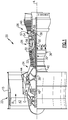
- FIG. 1 schematically illustrates a gas turbine engine 20.
- the gas turbine engine 20 is disclosed herein as a two-spool turbofan that generally incorporates a fan section 22, a compressor section 24, a combustor section 26 and a turbine section 28.
- the fan section 22 drives air along a bypass flow path B in a bypass duct defined within a housing 15, such as a fan case or nacelle, and also drives air along a core flow path C for compression and communication into the combustor section 26 then expansion through the turbine section 28.
- the exemplary engine 20 generally includes a low speed spool 30 and a high speed spool 32 mounted for rotation about an engine central longitudinal axis A relative to an engine static structure 36 via several bearing systems 38. It should be understood that various bearing systems 38 at various locations may alternatively or additionally be provided, and the location of bearing systems 38 may be varied as appropriate to the application.
- the low speed spool 30 generally includes an inner shaft 40 that interconnects, a first (or low) pressure compressor 44 and a first (or low) pressure turbine 46.
- the inner shaft 40 is connected to the fan 42 through a speed change mechanism, which in exemplary gas turbine engine 20 is illustrated as a geared architecture 48 to drive a fan 42 at a lower speed than the low speed spool 30.
- the high speed spool 32 includes an outer shaft 50 that interconnects a second (or high) pressure compressor 52 and a second (or high) pressure turbine 54.
- a combustor 56 is arranged in exemplary gas turbine 20 between the high pressure compressor 52 and the high pressure turbine 54.
- a mid-turbine frame 57 of the engine static structure 36 may be arranged generally between the high pressure turbine 54 and the low pressure turbine 46.
- the mid-turbine frame 57 further supports bearing systems 38 in the turbine section 28.
- the inner shaft 40 and the outer shaft 50 are concentric and rotate via bearing systems 38 about the engine central longitudinal axis A which is colline
- the core airflow is compressed by the low pressure compressor 44 then the high pressure compressor 52, mixed and burned with fuel in the combustor 56, then expanded over the high pressure turbine 54 and low pressure turbine 46.
- the mid-turbine frame 57 includes airfoils 59 which are in the core airflow path C.
- the turbines 46, 54 rotationally drive the respective low speed spool 30 and high speed spool 32 in response to the expansion.
- gear system 48 may be located aft of the low pressure compressor, or aft of the combustor section 26 or even aft of turbine section 28, and fan 42 may be positioned forward or aft of the location of gear system 48.
- the engine 20 in one example is a high-bypass geared aircraft engine.
- the engine 20 bypass ratio is greater than about six (6), with an example embodiment being greater than about ten (10)
- the geared architecture 48 is an epicyclic gear train, such as a planetary gear system or other gear system, with a gear reduction ratio of greater than about 2.3
- the low pressure turbine 46 has a pressure ratio that is greater than about five.
- the engine 20 bypass ratio is greater than about ten (10:1)
- the fan diameter is significantly larger than that of the low pressure compressor 44
- the low pressure turbine 46 has a pressure ratio that is greater than about five 5:1.
- Low pressure turbine 46 pressure ratio is pressure measured prior to inlet of low pressure turbine 46 as related to the pressure at the outlet of the low pressure turbine 46 prior to an exhaust nozzle.
- the geared architecture 48 may be an epicycle gear train, such as a planetary gear system or other gear system, with a gear reduction ratio of greater than about 2.3:1 and less than about 5:1. It should be understood, however, that the above parameters are only exemplary of one embodiment of a geared architecture engine and that the present disclosure is applicable to other gas turbine engines including direct drive turbofans.
- the fan section 22 of the engine 20 is designed for a particular flight condition -- typically cruise at about 0.8 Mach and about 35,000 feet (10,668 meters).
- the flight condition of 0.8 Mach and 35,000 ft (10,668 meters), with the engine at its best fuel consumption - also known as "bucket cruise Thrust Specific Fuel Consumption ('TSFC')" - is the industry standard parameter of lbm of fuel being burned divided by lbf of thrust the engine produces at that minimum point.
- "Low fan pressure ratio” is the pressure ratio across the fan blade alone, without a Fan Exit Guide Vane (“FEGV”) system.
- the low fan pressure ratio as disclosed herein according to one non-limiting embodiment is less than about 1.45.
- Low corrected fan tip speed is the actual fan tip speed in ft/sec divided by an industry standard temperature correction of [(Tram °R) / (518.7 °R)] 0.5 .
- the "Low corrected fan tip speed” as disclosed herein according to one non-limiting embodiment is less than about 1150 ft / second (350.5 meters/second).
- a carbon seal assembly 60 completely surrounds the outer shaft 50.
- the carbon seal assembly 60 could be located around other shafts in the gas turbine engine 20, such as the inner shaft 40 or shafts within the geared architecture 48.
- the carbon seal assembly 60 at least includes a carrier or housing 62 that at least partially enclosing a carbon seal 64.
- the housing 62 and the carbon seal 64 each form a single continuous ring.
- the housing 62 and the carbon seal 64 include multiple circumferential segments jointed together to form a ring with joints or discontinuities.
- the carbon seal 64 can be comprised of a suitable electrocarbon, such as an electrographitic grade carbon, salt impregnated carbon-graphite, resin impregnated carbon-graphite, non-impregnated carbon graphite, salt impregnated electrographite, non-impregnated electrographite either entirely or partially.
- the housing 62 includes an axially extending portion 66 and a radially extending portion 68 that each form a ring.
- the radially extending portion 68 extends radially inward from an axially forward end of the axially extending portion 66 such that a radially inner end of the radially extending portion 68 is a free end and spaced from the outer shaft 50.
- radial or radially and axial or axially is in relation to the central longitudinal axis A and upstream or downstream is in relation to a flow of air through the gas turbine engine 20.
- the fan section 22 is located adjacent an axially forward or upstream end of the gas turbine engine 20 and the turbine section 28 is located adjacent an axially aft or downstream end of the gas turbine engine 20.
- the radially extending portion 68 forms a seal flange and includes an axially forward surface 70 at least partially defining an oil retaining portion 72 that is separated from an air portion 74 on an opposite side of the carbon seal assembly 60.
- An axially aft surface 76 is located on an opposite side of the radially extending portion 68 from the axially forward surface 70.
- the axially aft surface 76 is at least partially covered with multiple layers of coatings.
- a first coating is a carbide based coating 78, such as tungsten carbide-cobalt or chromium carbide, that is directly in contact with the axially surface 76.
- a second layer is a diamond-like carbon (“DLC") coating 80 that covers the carbide based coating 78 and is at least partially spaced form the axially aft surface 76 by the carbide based coating 78. Therefore, the carbon seal 64 is spaced from and not in contact with the housing 62 due at least in part to the carbide based coating 78 and the diamond-like carbon coating 80. Both the carbide based coating 78 and the diamond-like carbon coating 80 extend circumferentially with the radially extending portion 68 to form a complete ring of separation between the radially extending surface 68 and the carbon seal 64.
- DLC diamond-like carbon
- the carbide based coating 78 is applied directly to the axially aft surface 76 on the radially extending portion 68 through one of a high velocity oxygen fuel coating process or an APS coating process.
- the diamond-like carbon coating 80 is spaced from the axially aft surface 76 and the housing 62 by the carbide based coating 78 and is applied through one of a physical vapor deposition ("PVD") or a chemical vapor deposition (“CVD”) process.
- PVD physical vapor deposition
- CVD chemical vapor deposition
- the thicknesses of the carbide based coating 78 and the diamond-like carbon coating 80 are for illustrative purposes only and are not to scale.
- the carbide based coating 78 can have a thickness of between 76 and 152 micrometers (3-6 thousandths of an inch) and the diamond-like carbon coating 80 is approximately 1 micrometer (0.04 thousandths of an inch).
- the diamond-like carbon coating 80 is a thin film formed from a DLC material having sp2 and sp3 content.
- the sp2 content is indicative of graphitic content of the material, while the sp3 content is indicative of the diamond-like content of the material.
- the sp2 content of the film material is greater than the sp3 content.
- Another aspect for characterizing the DLC material is referred to as micro-Raman. Micro-Raman provides a 'G' peak and a 'D' peak, which refer to disorder and graphite respectively.
- the diamond-like carbon coating 80 can be doped with carbide-forming metals to improve wear resistance of the film.
- carbide-forming metals can include tungsten or silicon or combinations thereof, and these metals help to form carbides in the film which increase wear resistance.
- the carbide-forming metal can also or in addition be chromium or molybdenum or combinations thereof, which can also assist in the formation of carbides.
- the diamond-like carbon coating 80 in accordance with the present disclosure produces a low friction and wear-resistant carbon-based seal interface which, for example, can operate effectively between 200 and 350°F (between 93 and 177°C), under elevated sliding velocities. This, in turn, can reduce sub-surface heating (for example due to frictional heating) by reducing the friction coefficient and improving the break-in phase, which will consequently improve long term wear resistance of the carbon seal 64.
- the diamond-like carbon coating 80 creates a carbon-carbon interface with low friction from the beginning of operation, and therefore produces a very short break-in phase.
- a transfer film or graphitic material 92 is formed over the diamond-like carbon coating 80.
- the graphitic material 92 remains through steady state operation of the carbon seal 64 to reduce wear on the carbon seal 64.
- the carbon seal 64 can also include film controllers to reduce the generation of excess graphitic material 92.
- the carbon seal 64 is biased towards the outer shaft 50 with a garter spring 65 when the carbon seal 64 is segmented.
- the garter spring 65 is located in a groove 84 in a radially outer surface of the carbon seal 64 and surrounds the carbon seal 64 to apply a compressive force to the carbon seal 64.
- One feature of the garter spring 65 is a reduction in leakage between the carbon seal 64 and the outer shaft 50 due to the compressive force applied.
- the outer shaft 50 can include a velocity relative to the carbon seal 64 of at least 152 m/s (approximately 500 ft/s) or at least 183 m/s (approximately 600 ft/s).
- the carbon seal 64 includes a projection 86 adjacent the outer shaft 50 having a shaft contacting surface 90.
- the projection 86 forms a clearance gap 88 between the carbon seal 64 and the outer shaft 50.
- the clearance gap 88 results from the projection 86 having a smaller axial dimension than the carbon seal 64.
- the projection 86 includes an axial dimension P1 extending from an axially forward most edge to an axially aft most edge of the shaft contacting surface 90.
- the carbon seal 64 includes an axial dimension C1 that is greater than the axial dimension P1.
- the axial dimension P1 is less than 25% of the axial dimension C1.
- the axial dimension P1 is less than 50% of the axial dimension C1.
- the carbon seal 64 can move relative to the housing 62. Without the coatings 78, 80, the carbon seal 64 is in direct contact with the metallic housing 62 which can cause wear on an axially upstream side 67 of the carbon seal 64.
- One feature of the coatings 78 and 80 is that the carbon seal 64 contacts the diamond-like carbon coating 80 to create a carbon on carbon interface. Additionally, movement between the carbon seal 64 and the housing 62 results in the formation of the graphitic material 92 between the diamond-like carbon coating 80 and the carbon seal 64 as described above.
- the graphitic material 92 reduces frictional forces between the diamond-like carbon coating 80 and the carbon seal 64 to reduce wear on the axially upstream side 67 of the carbon seal 64.
- the illustrated example shows the graphitic material 92 located between a portion of the diamond-like carbon coating 80 and the carbon seal 64, the graphitic material 92 can form in a majority of the contact area between diamond-like carbon coating 80 and carbon seal 64.
Landscapes
- Engineering & Computer Science (AREA)
- General Engineering & Computer Science (AREA)
- Mechanical Engineering (AREA)
- Chemical & Material Sciences (AREA)
- Combustion & Propulsion (AREA)
- Structures Of Non-Positive Displacement Pumps (AREA)
- Gasket Seals (AREA)
Abstract
Description
- The present disclosure relates to seals and, more particularly, to carbon seals used in gas turbine engines.
- A gas turbine engine typically includes a fan section, a compressor section, a combustor section, and a turbine section. Air entering the compressor section is compressed and delivered into the combustor section where it is mixed with fuel and ignited to generate a high-speed exhaust gas flow. The high-speed exhaust gas flow expands through the turbine section to drive the compressor and the fan section.
- In one example, circumferential carbon seals are used in bearing compartments of gas turbine engines to provide a seal between oil used to lubricate parts of the gas turbine engine and other parts of the gas turbine engine. Bearing assemblies may also support a rotating shaft of the gas turbine engine. The circumferential carbon seals may be sealed against a seal carrier or housing against rotating seal components of the gas turbine engine.
- In one exemplary embodiment, a seal assembly includes a housing that includes a seal flange at least partially defining a seal opening. A carbon seal is located at least partially in the seal opening and includes a first axially facing surface. The seal flange includes an axially facing surface that has a carbide based coating and a diamond-like carbon coating in engagement with the first axially facing surface on the carbon seal.
- In a further embodiment of any of the above, the carbide based coating is in direct contact with the seal flange.
- In a further embodiment of any of the above, the diamond-like carbon coating is in direct contact with the carbide based coating on the carbon seal.
- In a further embodiment of any of the above, the carbide based coating includes at least one of a tungsten carbide-cobalt or a chromium carbide.
- In a further embodiment of any of the above, the carbide based coating and the diamond-like carbon coating extend circumferentially with the flange.
- In a further embodiment of any of the above, the carbide based coating and the diamond-like carbon coating create an axial separation between the flange and the carbon seal.
- In a further embodiment of any of the above, the carbon seal includes an electrocarbon grade carbon.
- In a further embodiment of any of the above, the diamond-like carbon coating is silicon doped.
- In a further embodiment of any of the above, the carbide based and the diamond-like carbon coating separate the housing from contacting the carbon seal.
- In a further embodiment of any of the above, a shaft is located adjacent a radially inner contact surface of the carbon seal.
- In a further embodiment of any of the above, the carbon seal includes a first axial dimension and the radially inner contact surface includes a second axial dimension less than the first axial dimension.
- In a further embodiment of any of the above, the radially inner contact surface is located on an inner side of a projection of the carbon seal.
- In a further embodiment of any of the above, the carbide based coating is between 76 and 152 micrometers thick.
- In a further embodiment of any of the above, the diamond-like carbon coating is approximately 1 micrometer thick.
- In another exemplary embodiment, a method of using a seal assembly includes locating a carbon seal adjacent a housing and separating the carbon seal from the housing with a carbide based coating and a diamond-like carbon coating. A lubricant is generated between the carbon seal and the diamond-like carbon coating.
- In a further embodiment of any of the above, the carbide based coating is in direct contact with the housing. The diamond-like carbon coating is at least partially spaced from the housing by the carbide. The carbide based coating includes at least one of tungsten carbide-cobalt or chromium carbide.
- In a further embodiment of any of the above, generating the lubricant includes forming a graphitic material between the interface of the carbon seal and the diamond-like carbon coating.
- In a further embodiment of any of the above, a shaft is rotated adjacent the carbon seal and it includes a velocity of at least 152 m/s relative to the carbon seal.
- In a further embodiment of any of the above, the carbide based coating is applied through at least one of a high velocity oxygen fuel coating process or an APS coating process.
- In a further embodiment of any of the above, the diamond-like carbon is applied through at least one of a PVD or CVD process.
- The various features and advantages of the present disclosure will become apparent to those skilled in the art from the following detailed description. The drawings that accompany the detailed description can be briefly described as follows.
-
Figure 1 is a schematic view of a non-limiting example of a gas turbine engine. -
Figure 2 illustrates an axial view of a shaft and a carbon seal assembly. -
Figure 3 illustrates a cross-sectional view taken along line 3-3 ofFigure 2 . -
Figure 1 schematically illustrates agas turbine engine 20. Thegas turbine engine 20 is disclosed herein as a two-spool turbofan that generally incorporates afan section 22, acompressor section 24, a combustor section 26 and aturbine section 28. Thefan section 22 drives air along a bypass flow path B in a bypass duct defined within ahousing 15, such as a fan case or nacelle, and also drives air along a core flow path C for compression and communication into the combustor section 26 then expansion through theturbine section 28. Although depicted as a two-spool turbofan gas turbine engine in the disclosed non-limiting embodiment, it should be understood that the concepts described herein are not limited to use with two-spool turbofans as the teachings may be applied to other types of turbine engines including three-spool architectures. - The
exemplary engine 20 generally includes alow speed spool 30 and ahigh speed spool 32 mounted for rotation about an engine central longitudinal axis A relative to an enginestatic structure 36 viaseveral bearing systems 38. It should be understood thatvarious bearing systems 38 at various locations may alternatively or additionally be provided, and the location ofbearing systems 38 may be varied as appropriate to the application. - The
low speed spool 30 generally includes aninner shaft 40 that interconnects, a first (or low)pressure compressor 44 and a first (or low)pressure turbine 46. Theinner shaft 40 is connected to thefan 42 through a speed change mechanism, which in exemplarygas turbine engine 20 is illustrated as a gearedarchitecture 48 to drive afan 42 at a lower speed than thelow speed spool 30. Thehigh speed spool 32 includes anouter shaft 50 that interconnects a second (or high)pressure compressor 52 and a second (or high)pressure turbine 54. Acombustor 56 is arranged inexemplary gas turbine 20 between thehigh pressure compressor 52 and thehigh pressure turbine 54. Amid-turbine frame 57 of the enginestatic structure 36 may be arranged generally between thehigh pressure turbine 54 and thelow pressure turbine 46. Themid-turbine frame 57 further supports bearingsystems 38 in theturbine section 28. Theinner shaft 40 and theouter shaft 50 are concentric and rotate viabearing systems 38 about the engine central longitudinal axis A which is collinear with their longitudinal axes. - The core airflow is compressed by the
low pressure compressor 44 then thehigh pressure compressor 52, mixed and burned with fuel in thecombustor 56, then expanded over thehigh pressure turbine 54 andlow pressure turbine 46. Themid-turbine frame 57 includesairfoils 59 which are in the core airflow path C. Theturbines low speed spool 30 andhigh speed spool 32 in response to the expansion. It will be appreciated that each of the positions of thefan section 22,compressor section 24, combustor section 26,turbine section 28, and fandrive gear system 48 may be varied. For example,gear system 48 may be located aft of the low pressure compressor, or aft of the combustor section 26 or even aft ofturbine section 28, andfan 42 may be positioned forward or aft of the location ofgear system 48. - The
engine 20 in one example is a high-bypass geared aircraft engine. In a further example, theengine 20 bypass ratio is greater than about six (6), with an example embodiment being greater than about ten (10), the gearedarchitecture 48 is an epicyclic gear train, such as a planetary gear system or other gear system, with a gear reduction ratio of greater than about 2.3 and thelow pressure turbine 46 has a pressure ratio that is greater than about five. In one disclosed embodiment, theengine 20 bypass ratio is greater than about ten (10:1), the fan diameter is significantly larger than that of thelow pressure compressor 44, and thelow pressure turbine 46 has a pressure ratio that is greater than about five 5:1.Low pressure turbine 46 pressure ratio is pressure measured prior to inlet oflow pressure turbine 46 as related to the pressure at the outlet of thelow pressure turbine 46 prior to an exhaust nozzle. The gearedarchitecture 48 may be an epicycle gear train, such as a planetary gear system or other gear system, with a gear reduction ratio of greater than about 2.3:1 and less than about 5:1. It should be understood, however, that the above parameters are only exemplary of one embodiment of a geared architecture engine and that the present disclosure is applicable to other gas turbine engines including direct drive turbofans. - A significant amount of thrust is provided by the bypass flow B due to the high bypass ratio. The
fan section 22 of theengine 20 is designed for a particular flight condition -- typically cruise at about 0.8 Mach and about 35,000 feet (10,668 meters). The flight condition of 0.8 Mach and 35,000 ft (10,668 meters), with the engine at its best fuel consumption - also known as "bucket cruise Thrust Specific Fuel Consumption ('TSFC')" - is the industry standard parameter of lbm of fuel being burned divided by lbf of thrust the engine produces at that minimum point. "Low fan pressure ratio" is the pressure ratio across the fan blade alone, without a Fan Exit Guide Vane ("FEGV") system. The low fan pressure ratio as disclosed herein according to one non-limiting embodiment is less than about 1.45. "Low corrected fan tip speed" is the actual fan tip speed in ft/sec divided by an industry standard temperature correction of [(Tram °R) / (518.7 °R)]0.5. The "Low corrected fan tip speed" as disclosed herein according to one non-limiting embodiment is less than about 1150 ft / second (350.5 meters/second). - As shown in
Figures 2 and 3 , acarbon seal assembly 60 completely surrounds theouter shaft 50. However, thecarbon seal assembly 60 could be located around other shafts in thegas turbine engine 20, such as theinner shaft 40 or shafts within the gearedarchitecture 48. Thecarbon seal assembly 60 at least includes a carrier orhousing 62 that at least partially enclosing acarbon seal 64. - In the illustrated example, the
housing 62 and thecarbon seal 64 each form a single continuous ring. However, in another example, thehousing 62 and thecarbon seal 64 include multiple circumferential segments jointed together to form a ring with joints or discontinuities. Thecarbon seal 64 can be comprised of a suitable electrocarbon, such as an electrographitic grade carbon, salt impregnated carbon-graphite, resin impregnated carbon-graphite, non-impregnated carbon graphite, salt impregnated electrographite, non-impregnated electrographite either entirely or partially. - As shown in
Figure 3 , thehousing 62 includes anaxially extending portion 66 and aradially extending portion 68 that each form a ring. In the illustrated example, theradially extending portion 68 extends radially inward from an axially forward end of theaxially extending portion 66 such that a radially inner end of theradially extending portion 68 is a free end and spaced from theouter shaft 50. In this disclosure, radial or radially and axial or axially is in relation to the central longitudinal axis A and upstream or downstream is in relation to a flow of air through thegas turbine engine 20. Additionally, thefan section 22 is located adjacent an axially forward or upstream end of thegas turbine engine 20 and theturbine section 28 is located adjacent an axially aft or downstream end of thegas turbine engine 20. - The
radially extending portion 68 forms a seal flange and includes an axiallyforward surface 70 at least partially defining anoil retaining portion 72 that is separated from anair portion 74 on an opposite side of thecarbon seal assembly 60. An axiallyaft surface 76 is located on an opposite side of theradially extending portion 68 from the axiallyforward surface 70. The axially aftsurface 76 is at least partially covered with multiple layers of coatings. A first coating is a carbide based coating 78, such as tungsten carbide-cobalt or chromium carbide, that is directly in contact with theaxially surface 76. A second layer is a diamond-like carbon ("DLC") coating 80 that covers the carbide based coating 78 and is at least partially spaced form the axially aftsurface 76 by the carbide based coating 78. Therefore, thecarbon seal 64 is spaced from and not in contact with thehousing 62 due at least in part to the carbide based coating 78 and the diamond-like carbon coating 80. Both the carbide based coating 78 and the diamond-like carbon coating 80 extend circumferentially with theradially extending portion 68 to form a complete ring of separation between theradially extending surface 68 and thecarbon seal 64. - In the illustrated example, the carbide based coating 78 is applied directly to the axially aft
surface 76 on theradially extending portion 68 through one of a high velocity oxygen fuel coating process or an APS coating process. The diamond-like carbon coating 80 is spaced from the axially aftsurface 76 and thehousing 62 by the carbide based coating 78 and is applied through one of a physical vapor deposition ("PVD") or a chemical vapor deposition ("CVD") process. In the illustrated example, the thicknesses of the carbide based coating 78 and the diamond-like carbon coating 80 are for illustrative purposes only and are not to scale. For example, the carbide based coating 78 can have a thickness of between 76 and 152 micrometers (3-6 thousandths of an inch) and the diamond-like carbon coating 80 is approximately 1 micrometer (0.04 thousandths of an inch). - The diamond-like carbon coating 80 is a thin film formed from a DLC material having sp2 and sp3 content. The sp2 content is indicative of graphitic content of the material, while the sp3 content is indicative of the diamond-like content of the material. In one non-limiting configuration, the sp2 content of the film material is greater than the sp3 content. Another aspect for characterizing the DLC material is referred to as micro-Raman. Micro-Raman provides a 'G' peak and a 'D' peak, which refer to disorder and graphite respectively. The diamond-like carbon coating 80 film for use in the present disclosure can have a I(D)/I(G) peak ratio of < or = 1.0 based on micro-Raman analysis.
- In another non-limiting configuration, the diamond-like carbon coating 80 can be doped with carbide-forming metals to improve wear resistance of the film. Such carbide- forming metals can include tungsten or silicon or combinations thereof, and these metals help to form carbides in the film which increase wear resistance. In some instances, the carbide-forming metal can also or in addition be chromium or molybdenum or combinations thereof, which can also assist in the formation of carbides.
- It should be appreciated that the diamond-like carbon coating 80 in accordance with the present disclosure produces a low friction and wear-resistant carbon-based seal interface which, for example, can operate effectively between 200 and 350°F (between 93 and 177°C), under elevated sliding velocities. This, in turn, can reduce sub-surface heating (for example due to frictional heating) by reducing the friction coefficient and improving the break-in phase, which will consequently improve long term wear resistance of the
carbon seal 64. - The diamond-like carbon coating 80 creates a carbon-carbon interface with low friction from the beginning of operation, and therefore produces a very short break-in phase. During initial operation, a transfer film or
graphitic material 92 is formed over the diamond-like carbon coating 80. Thegraphitic material 92 remains through steady state operation of thecarbon seal 64 to reduce wear on thecarbon seal 64. Thecarbon seal 64 can also include film controllers to reduce the generation of excessgraphitic material 92. - The
carbon seal 64 is biased towards theouter shaft 50 with agarter spring 65 when thecarbon seal 64 is segmented. Thegarter spring 65 is located in agroove 84 in a radially outer surface of thecarbon seal 64 and surrounds thecarbon seal 64 to apply a compressive force to thecarbon seal 64. One feature of thegarter spring 65 is a reduction in leakage between thecarbon seal 64 and theouter shaft 50 due to the compressive force applied. Theouter shaft 50 can include a velocity relative to thecarbon seal 64 of at least 152 m/s (approximately 500 ft/s) or at least 183 m/s (approximately 600 ft/s). - In the illustrated example, the
carbon seal 64 includes aprojection 86 adjacent theouter shaft 50 having ashaft contacting surface 90. Theprojection 86 forms aclearance gap 88 between thecarbon seal 64 and theouter shaft 50. Theclearance gap 88 results from theprojection 86 having a smaller axial dimension than thecarbon seal 64. In the illustrated example, theprojection 86 includes an axial dimension P1 extending from an axially forward most edge to an axially aft most edge of theshaft contacting surface 90. Thecarbon seal 64 includes an axial dimension C1 that is greater than the axial dimension P1. In the illustrated example, the axial dimension P1 is less than 25% of the axial dimension C1. In another example, the axial dimension P1 is less than 50% of the axial dimension C1. - During operation of the
seal assembly 60 in thegas turbine engine 20, thecarbon seal 64 can move relative to thehousing 62. Without the coatings 78, 80, thecarbon seal 64 is in direct contact with themetallic housing 62 which can cause wear on an axiallyupstream side 67 of thecarbon seal 64. One feature of the coatings 78 and 80 is that thecarbon seal 64 contacts the diamond-like carbon coating 80 to create a carbon on carbon interface. Additionally, movement between thecarbon seal 64 and thehousing 62 results in the formation of thegraphitic material 92 between the diamond-like carbon coating 80 and thecarbon seal 64 as described above. Thegraphitic material 92 reduces frictional forces between the diamond-like carbon coating 80 and thecarbon seal 64 to reduce wear on the axiallyupstream side 67 of thecarbon seal 64. Although the illustrated example shows thegraphitic material 92 located between a portion of the diamond-like carbon coating 80 and thecarbon seal 64, thegraphitic material 92 can form in a majority of the contact area between diamond-like carbon coating 80 andcarbon seal 64. - The foregoing description shall be interpreted as illustrative and not in any limiting sense. A worker of ordinary skill in the art would understand that certain modifications could come within the scope of this disclosure. For these reasons, the following claim should be studied to determine the true scope and content of this disclosure.
Claims (15)
- A seal assembly (60) comprising:a housing (62) including a seal flange (68) at least partially defining a seal opening; anda carbon seal (64) located at least partially in the seal opening and including a first axially facing surface (67);wherein the seal flange (68) includes an axially facing surface (76) having a carbide based coating (78) and a diamond-like carbon coating (80) in engagement with the first axially facing surface (67) on the carbon seal (64).
- The assembly (60) of claim 1, wherein the carbide based coating (78) is in direct contact with the seal flange (68), and/or the diamond-like carbon coating (80) is in direct contact with the carbide based coating (78) on the carbon seal (64).
- The assembly (60) of any preceding claim, wherein the carbide based coating (78) and the diamond-like carbon coating (80) extend circumferentially with the flange (68).
- The assembly (60) of any preceding claim, wherein the carbide based coating (78) and the diamond-like carbon coating (80) create an axial separation between the flange (68) and the carbon seal (64).
- The assembly (60) of any preceding claim, wherein the carbon seal (64) includes an electrocarbon grade carbon, the carbide based coating (78) includes at least one of a tungsten carbide-cobalt or a chromium carbide, and/or the diamond-like carbon coating (80) is silicon doped.
- The assembly (60) of any preceding claim, wherein the carbide based and the diamond-like carbon coatings (78, 80) separate the housing (62) from contacting the carbon seal (64).
- The assembly (60) of any preceding claim, further comprising a shaft (50) located adjacent a radially inner contact surface (90) of the carbon seal (64).
- The assembly (60) of claim 7, wherein the carbon seal (64) includes a first axial dimension (C1) and the radially inner contact surface (90) includes a second axial dimension (P1) less than the first axial dimension (C1).
- The assembly (60) of claim 7 or 8, wherein the radially inner contact surface (90) is located on an inner side of a projection (86) of the carbon seal (64).
- The assembly (60) of any preceding claim, wherein the carbide based coating (78) is between 76 and 152 micrometers thick and/or the diamond-like carbon coating (80) is approximately 1 micrometer thick.
- A method of using a seal assembly (60), the method comprising:locating a carbon seal (64) adjacent a housing (62);separating the carbon seal (64) from the housing (62) with a carbide based coating (78) and a diamond-like carbon coating (80); andgenerating a lubricant between the carbon seal (64) and the diamond-like carbon coating (80).
- The method of claim 11, wherein the carbide based coating (78) is in direct contact with the housing (62) and the diamond-like carbon coating (80) is at least partially spaced from the housing (62) by the carbide based coating (78), and the carbide based coating (78) includes at least one of tungsten carbide-cobalt or chromium carbide.
- The method of claim 11 or 12, wherein generating the lubricant includes forming a graphitic material (92) between the interface of the carbon seal (64) and the diamond-like carbon coating (80).
- The method of claim 11, 12 or 13, further comprising rotating a shaft (50) adjacent the carbon seal (64) and the shaft (50) includes a velocity of at least 152 m/s relative to the carbon seal (64).
- The method of any of claims 11 to 14, wherein the carbide based coating (78) is applied through at least one of a high velocity oxygen fuel coating process or an APS coating process, and/or the diamond-like carbon (80) is applied through at least one of a PVD or CVD process.
Applications Claiming Priority (1)
| Application Number | Priority Date | Filing Date | Title |
|---|---|---|---|
| US16/791,269 US11746907B2 (en) | 2020-02-14 | 2020-02-14 | Carbon seal assembly |
Publications (2)
| Publication Number | Publication Date |
|---|---|
| EP3865673A1 true EP3865673A1 (en) | 2021-08-18 |
| EP3865673B1 EP3865673B1 (en) | 2023-04-12 |
Family
ID=74595180
Family Applications (1)
| Application Number | Title | Priority Date | Filing Date |
|---|---|---|---|
| EP21156872.0A Active EP3865673B1 (en) | 2020-02-14 | 2021-02-12 | Carbon seal assembly |
Country Status (2)
| Country | Link |
|---|---|
| US (2) | US11746907B2 (en) |
| EP (1) | EP3865673B1 (en) |
Cited By (1)
| Publication number | Priority date | Publication date | Assignee | Title |
|---|---|---|---|---|
| WO2026064506A1 (en) * | 2024-09-18 | 2026-03-26 | Rtx Corporation | Turbine engine rotor piston seal ring contact hard coatings |
Families Citing this family (2)
| Publication number | Priority date | Publication date | Assignee | Title |
|---|---|---|---|---|
| EP4466476A1 (en) | 2022-01-21 | 2024-11-27 | RTX Corporation | Carbon face seal |
| US12060797B2 (en) | 2022-01-21 | 2024-08-13 | Rtx Corporation | Carbon face seal |
Citations (6)
| Publication number | Priority date | Publication date | Assignee | Title |
|---|---|---|---|---|
| WO2013053411A1 (en) * | 2011-10-14 | 2013-04-18 | Eagleburgmann Germany Gmbh & Co. Kg | Slide ring of a slide ring seal arrangement, having properties which lengthen the service life, and method for the production thereof |
| US20140265145A1 (en) * | 2013-03-15 | 2014-09-18 | Rolls-Royce Corporation | Seals for a gas turbine engine |
| EP3270015A1 (en) * | 2015-03-09 | 2018-01-17 | Nippon Pillar Packing Co., Ltd. | Floating ring mechanical seal |
| EP3284980A1 (en) * | 2015-04-16 | 2018-02-21 | Eagle Industry Co., Ltd. | Sliding part |
| US20190234240A1 (en) * | 2018-01-31 | 2019-08-01 | Pratt & Whitney Canada Corp. | Non-contacting seal with non-abradable coating |
| EP3626694A1 (en) * | 2018-09-19 | 2020-03-25 | United Technologies Corporation | Seal assembly for gas turbine engine |
Family Cites Families (16)
| Publication number | Priority date | Publication date | Assignee | Title |
|---|---|---|---|---|
| US4202553A (en) * | 1978-11-03 | 1980-05-13 | Ceramic Coating Company | Seal cartridge for agitator shaft of a chemical reactor |
| US6145843A (en) * | 1998-10-19 | 2000-11-14 | Stein Seal Company | Hydrodynamic lift seal for use with compressible fluids |
| US7581734B1 (en) * | 2000-05-01 | 2009-09-01 | Schlumberger Technology Corporation | Peek coated seal surfaces |
| US20020079647A1 (en) * | 2000-12-26 | 2002-06-27 | Theodore Michael G. | Mechanical seal with embedded lubrication |
| US7883093B2 (en) * | 2004-07-02 | 2011-02-08 | Nippon Pillar Packing Co., Ltd. | Mechanical seal |
| CN101133184A (en) | 2005-03-02 | 2008-02-27 | 株式会社荏原制作所 | Diamond-coated bearing or seal structures and fluid machinery incorporating them |
| JP2006266285A (en) * | 2005-03-22 | 2006-10-05 | Kayaba Ind Co Ltd | mechanical seal |
| JP5244495B2 (en) * | 2008-08-06 | 2013-07-24 | 三菱重工業株式会社 | Parts for rotating machinery |
| CN102822546B (en) | 2010-03-30 | 2015-10-14 | Ntn株式会社 | Rolling bearing |
| DE202010011173U1 (en) * | 2010-08-09 | 2011-12-22 | Eagleburgmann Germany Gmbh & Co. Kg | Sliding ring with improved inlet properties |
| US9358613B2 (en) * | 2013-04-08 | 2016-06-07 | Baker Hughes Incorporated | Hydrophobic porous hard coating with lubricant, method for making and use of same |
| US20150345642A1 (en) * | 2014-05-29 | 2015-12-03 | Caterpillar Inc. | Thin film coating on mechanical face seals |
| US20150353856A1 (en) | 2014-06-04 | 2015-12-10 | Ardy S. Kleyman | Fluid tight low friction coating systems for dynamically engaging load bearing surfaces |
| US10480657B1 (en) | 2016-10-07 | 2019-11-19 | S. E. Yandle, II | Mechanical pump seal |
| US10385921B2 (en) * | 2017-01-16 | 2019-08-20 | Aktiebolaget Skf | Combination bearing and seal assembly for rotatable shafts |
| US11255432B2 (en) * | 2019-04-05 | 2022-02-22 | Raytheon Technologies Corporation | Low friction, wear resistant piston seal |
-
2020
- 2020-02-14 US US16/791,269 patent/US11746907B2/en active Active
-
2021
- 2021-02-12 EP EP21156872.0A patent/EP3865673B1/en active Active
-
2023
- 2023-06-06 US US18/330,027 patent/US12292116B2/en active Active
Patent Citations (6)
| Publication number | Priority date | Publication date | Assignee | Title |
|---|---|---|---|---|
| WO2013053411A1 (en) * | 2011-10-14 | 2013-04-18 | Eagleburgmann Germany Gmbh & Co. Kg | Slide ring of a slide ring seal arrangement, having properties which lengthen the service life, and method for the production thereof |
| US20140265145A1 (en) * | 2013-03-15 | 2014-09-18 | Rolls-Royce Corporation | Seals for a gas turbine engine |
| EP3270015A1 (en) * | 2015-03-09 | 2018-01-17 | Nippon Pillar Packing Co., Ltd. | Floating ring mechanical seal |
| EP3284980A1 (en) * | 2015-04-16 | 2018-02-21 | Eagle Industry Co., Ltd. | Sliding part |
| US20190234240A1 (en) * | 2018-01-31 | 2019-08-01 | Pratt & Whitney Canada Corp. | Non-contacting seal with non-abradable coating |
| EP3626694A1 (en) * | 2018-09-19 | 2020-03-25 | United Technologies Corporation | Seal assembly for gas turbine engine |
Cited By (1)
| Publication number | Priority date | Publication date | Assignee | Title |
|---|---|---|---|---|
| WO2026064506A1 (en) * | 2024-09-18 | 2026-03-26 | Rtx Corporation | Turbine engine rotor piston seal ring contact hard coatings |
Also Published As
| Publication number | Publication date |
|---|---|
| US20210254719A1 (en) | 2021-08-19 |
| EP3865673B1 (en) | 2023-04-12 |
| US20230323951A1 (en) | 2023-10-12 |
| US12292116B2 (en) | 2025-05-06 |
| US11746907B2 (en) | 2023-09-05 |
Similar Documents
| Publication | Publication Date | Title |
|---|---|---|
| US12292116B2 (en) | Carbon seal assembly | |
| US10920617B2 (en) | Gas turbine engine seal ring assembly | |
| US11149651B2 (en) | Seal ring assembly for a gas turbine engine | |
| EP4006311B1 (en) | Face seal arrangement with reduced force and pressure | |
| EP3712469B1 (en) | Seal plate lubricant slinger | |
| EP3521572A1 (en) | Hydrostatic seal assembly with abradable teeth for gas turbine engine | |
| EP3865672B1 (en) | Carbon seal assembly | |
| US7435052B2 (en) | Shaft oil purge system | |
| US11499442B2 (en) | Bearing compartment seal configuration for a gas turbine engine | |
| US12291970B2 (en) | Carbon seal assembly | |
| US12359626B2 (en) | Rotating sleeve controlling clearance of seal assembly of gas turbine engine | |
| US11313280B2 (en) | Gas turbine engine including seal assembly with abradable coating and cutter | |
| EP4006310B1 (en) | Face seal arrangement with reduced balance ratio | |
| US20220268166A1 (en) | Non-contacting seal assembly with internal coating |
Legal Events
| Date | Code | Title | Description |
|---|---|---|---|
| PUAI | Public reference made under article 153(3) epc to a published international application that has entered the european phase |
Free format text: ORIGINAL CODE: 0009012 |
|
| STAA | Information on the status of an ep patent application or granted ep patent |
Free format text: STATUS: THE APPLICATION HAS BEEN PUBLISHED |
|
| AK | Designated contracting states |
Kind code of ref document: A1 Designated state(s): AL AT BE BG CH CY CZ DE DK EE ES FI FR GB GR HR HU IE IS IT LI LT LU LV MC MK MT NL NO PL PT RO RS SE SI SK SM TR |
|
| STAA | Information on the status of an ep patent application or granted ep patent |
Free format text: STATUS: REQUEST FOR EXAMINATION WAS MADE |
|
| 17P | Request for examination filed |
Effective date: 20220216 |
|
| RBV | Designated contracting states (corrected) |
Designated state(s): AL AT BE BG CH CY CZ DE DK EE ES FI FR GB GR HR HU IE IS IT LI LT LU LV MC MK MT NL NO PL PT RO RS SE SI SK SM TR |
|
| GRAP | Despatch of communication of intention to grant a patent |
Free format text: ORIGINAL CODE: EPIDOSNIGR1 |
|
| STAA | Information on the status of an ep patent application or granted ep patent |
Free format text: STATUS: GRANT OF PATENT IS INTENDED |
|
| INTG | Intention to grant announced |
Effective date: 20221018 |
|
| GRAS | Grant fee paid |
Free format text: ORIGINAL CODE: EPIDOSNIGR3 |
|
| GRAA | (expected) grant |
Free format text: ORIGINAL CODE: 0009210 |
|
| STAA | Information on the status of an ep patent application or granted ep patent |
Free format text: STATUS: THE PATENT HAS BEEN GRANTED |
|
| AK | Designated contracting states |
Kind code of ref document: B1 Designated state(s): AL AT BE BG CH CY CZ DE DK EE ES FI FR GB GR HR HU IE IS IT LI LT LU LV MC MK MT NL NO PL PT RO RS SE SI SK SM TR |
|
| REG | Reference to a national code |
Ref country code: GB Ref legal event code: FG4D |
|
| REG | Reference to a national code |
Ref country code: CH Ref legal event code: EP |
|
| REG | Reference to a national code |
Ref country code: DE Ref legal event code: R096 Ref document number: 602021001849 Country of ref document: DE |
|
| REG | Reference to a national code |
Ref country code: IE Ref legal event code: FG4D |
|
| REG | Reference to a national code |
Ref country code: AT Ref legal event code: REF Ref document number: 1559889 Country of ref document: AT Kind code of ref document: T Effective date: 20230515 |
|
| P01 | Opt-out of the competence of the unified patent court (upc) registered |
Effective date: 20230521 |
|
| REG | Reference to a national code |
Ref country code: LT Ref legal event code: MG9D |
|
| REG | Reference to a national code |
Ref country code: NL Ref legal event code: MP Effective date: 20230412 |
|
| REG | Reference to a national code |
Ref country code: AT Ref legal event code: MK05 Ref document number: 1559889 Country of ref document: AT Kind code of ref document: T Effective date: 20230412 |
|
| PG25 | Lapsed in a contracting state [announced via postgrant information from national office to epo] |
Ref country code: NL Free format text: LAPSE BECAUSE OF FAILURE TO SUBMIT A TRANSLATION OF THE DESCRIPTION OR TO PAY THE FEE WITHIN THE PRESCRIBED TIME-LIMIT Effective date: 20230412 |
|
| PG25 | Lapsed in a contracting state [announced via postgrant information from national office to epo] |
Ref country code: SE Free format text: LAPSE BECAUSE OF FAILURE TO SUBMIT A TRANSLATION OF THE DESCRIPTION OR TO PAY THE FEE WITHIN THE PRESCRIBED TIME-LIMIT Effective date: 20230412 Ref country code: PT Free format text: LAPSE BECAUSE OF FAILURE TO SUBMIT A TRANSLATION OF THE DESCRIPTION OR TO PAY THE FEE WITHIN THE PRESCRIBED TIME-LIMIT Effective date: 20230814 Ref country code: NO Free format text: LAPSE BECAUSE OF FAILURE TO SUBMIT A TRANSLATION OF THE DESCRIPTION OR TO PAY THE FEE WITHIN THE PRESCRIBED TIME-LIMIT Effective date: 20230712 Ref country code: ES Free format text: LAPSE BECAUSE OF FAILURE TO SUBMIT A TRANSLATION OF THE DESCRIPTION OR TO PAY THE FEE WITHIN THE PRESCRIBED TIME-LIMIT Effective date: 20230412 Ref country code: AT Free format text: LAPSE BECAUSE OF FAILURE TO SUBMIT A TRANSLATION OF THE DESCRIPTION OR TO PAY THE FEE WITHIN THE PRESCRIBED TIME-LIMIT Effective date: 20230412 |
|
| RAP4 | Party data changed (patent owner data changed or rights of a patent transferred) |
Owner name: RTX CORPORATION |
|
| PG25 | Lapsed in a contracting state [announced via postgrant information from national office to epo] |
Ref country code: RS Free format text: LAPSE BECAUSE OF FAILURE TO SUBMIT A TRANSLATION OF THE DESCRIPTION OR TO PAY THE FEE WITHIN THE PRESCRIBED TIME-LIMIT Effective date: 20230412 Ref country code: PL Free format text: LAPSE BECAUSE OF FAILURE TO SUBMIT A TRANSLATION OF THE DESCRIPTION OR TO PAY THE FEE WITHIN THE PRESCRIBED TIME-LIMIT Effective date: 20230412 Ref country code: LV Free format text: LAPSE BECAUSE OF FAILURE TO SUBMIT A TRANSLATION OF THE DESCRIPTION OR TO PAY THE FEE WITHIN THE PRESCRIBED TIME-LIMIT Effective date: 20230412 Ref country code: LT Free format text: LAPSE BECAUSE OF FAILURE TO SUBMIT A TRANSLATION OF THE DESCRIPTION OR TO PAY THE FEE WITHIN THE PRESCRIBED TIME-LIMIT Effective date: 20230412 Ref country code: IS Free format text: LAPSE BECAUSE OF FAILURE TO SUBMIT A TRANSLATION OF THE DESCRIPTION OR TO PAY THE FEE WITHIN THE PRESCRIBED TIME-LIMIT Effective date: 20230812 Ref country code: HR Free format text: LAPSE BECAUSE OF FAILURE TO SUBMIT A TRANSLATION OF THE DESCRIPTION OR TO PAY THE FEE WITHIN THE PRESCRIBED TIME-LIMIT Effective date: 20230412 Ref country code: GR Free format text: LAPSE BECAUSE OF FAILURE TO SUBMIT A TRANSLATION OF THE DESCRIPTION OR TO PAY THE FEE WITHIN THE PRESCRIBED TIME-LIMIT Effective date: 20230713 Ref country code: AL Free format text: LAPSE BECAUSE OF FAILURE TO SUBMIT A TRANSLATION OF THE DESCRIPTION OR TO PAY THE FEE WITHIN THE PRESCRIBED TIME-LIMIT Effective date: 20230412 |
|
| PG25 | Lapsed in a contracting state [announced via postgrant information from national office to epo] |
Ref country code: FI Free format text: LAPSE BECAUSE OF FAILURE TO SUBMIT A TRANSLATION OF THE DESCRIPTION OR TO PAY THE FEE WITHIN THE PRESCRIBED TIME-LIMIT Effective date: 20230412 |
|
| REG | Reference to a national code |
Ref country code: DE Ref legal event code: R097 Ref document number: 602021001849 Country of ref document: DE |
|
| PG25 | Lapsed in a contracting state [announced via postgrant information from national office to epo] |
Ref country code: SK Free format text: LAPSE BECAUSE OF FAILURE TO SUBMIT A TRANSLATION OF THE DESCRIPTION OR TO PAY THE FEE WITHIN THE PRESCRIBED TIME-LIMIT Effective date: 20230412 |
|
| PG25 | Lapsed in a contracting state [announced via postgrant information from national office to epo] |
Ref country code: SM Free format text: LAPSE BECAUSE OF FAILURE TO SUBMIT A TRANSLATION OF THE DESCRIPTION OR TO PAY THE FEE WITHIN THE PRESCRIBED TIME-LIMIT Effective date: 20230412 Ref country code: SK Free format text: LAPSE BECAUSE OF FAILURE TO SUBMIT A TRANSLATION OF THE DESCRIPTION OR TO PAY THE FEE WITHIN THE PRESCRIBED TIME-LIMIT Effective date: 20230412 Ref country code: RO Free format text: LAPSE BECAUSE OF FAILURE TO SUBMIT A TRANSLATION OF THE DESCRIPTION OR TO PAY THE FEE WITHIN THE PRESCRIBED TIME-LIMIT Effective date: 20230412 Ref country code: EE Free format text: LAPSE BECAUSE OF FAILURE TO SUBMIT A TRANSLATION OF THE DESCRIPTION OR TO PAY THE FEE WITHIN THE PRESCRIBED TIME-LIMIT Effective date: 20230412 Ref country code: DK Free format text: LAPSE BECAUSE OF FAILURE TO SUBMIT A TRANSLATION OF THE DESCRIPTION OR TO PAY THE FEE WITHIN THE PRESCRIBED TIME-LIMIT Effective date: 20230412 Ref country code: CZ Free format text: LAPSE BECAUSE OF FAILURE TO SUBMIT A TRANSLATION OF THE DESCRIPTION OR TO PAY THE FEE WITHIN THE PRESCRIBED TIME-LIMIT Effective date: 20230412 |
|
| PLBE | No opposition filed within time limit |
Free format text: ORIGINAL CODE: 0009261 |
|
| STAA | Information on the status of an ep patent application or granted ep patent |
Free format text: STATUS: NO OPPOSITION FILED WITHIN TIME LIMIT |
|
| 26N | No opposition filed |
Effective date: 20240115 |
|
| PG25 | Lapsed in a contracting state [announced via postgrant information from national office to epo] |
Ref country code: SI Free format text: LAPSE BECAUSE OF FAILURE TO SUBMIT A TRANSLATION OF THE DESCRIPTION OR TO PAY THE FEE WITHIN THE PRESCRIBED TIME-LIMIT Effective date: 20230412 |
|
| PG25 | Lapsed in a contracting state [announced via postgrant information from national office to epo] |
Ref country code: SI Free format text: LAPSE BECAUSE OF FAILURE TO SUBMIT A TRANSLATION OF THE DESCRIPTION OR TO PAY THE FEE WITHIN THE PRESCRIBED TIME-LIMIT Effective date: 20230412 Ref country code: IT Free format text: LAPSE BECAUSE OF FAILURE TO SUBMIT A TRANSLATION OF THE DESCRIPTION OR TO PAY THE FEE WITHIN THE PRESCRIBED TIME-LIMIT Effective date: 20230412 |
|
| PG25 | Lapsed in a contracting state [announced via postgrant information from national office to epo] |
Ref country code: MC Free format text: LAPSE BECAUSE OF FAILURE TO SUBMIT A TRANSLATION OF THE DESCRIPTION OR TO PAY THE FEE WITHIN THE PRESCRIBED TIME-LIMIT Effective date: 20230412 |
|
| REG | Reference to a national code |
Ref country code: CH Ref legal event code: PL |
|
| PG25 | Lapsed in a contracting state [announced via postgrant information from national office to epo] |
Ref country code: LU Free format text: LAPSE BECAUSE OF NON-PAYMENT OF DUE FEES Effective date: 20240212 |
|
| PG25 | Lapsed in a contracting state [announced via postgrant information from national office to epo] |
Ref country code: CH Free format text: LAPSE BECAUSE OF NON-PAYMENT OF DUE FEES Effective date: 20240229 |
|
| PG25 | Lapsed in a contracting state [announced via postgrant information from national office to epo] |
Ref country code: LU Free format text: LAPSE BECAUSE OF NON-PAYMENT OF DUE FEES Effective date: 20240212 Ref country code: CH Free format text: LAPSE BECAUSE OF NON-PAYMENT OF DUE FEES Effective date: 20240229 |
|
| PG25 | Lapsed in a contracting state [announced via postgrant information from national office to epo] |
Ref country code: BG Free format text: LAPSE BECAUSE OF FAILURE TO SUBMIT A TRANSLATION OF THE DESCRIPTION OR TO PAY THE FEE WITHIN THE PRESCRIBED TIME-LIMIT Effective date: 20230412 |
|
| PG25 | Lapsed in a contracting state [announced via postgrant information from national office to epo] |
Ref country code: BG Free format text: LAPSE BECAUSE OF FAILURE TO SUBMIT A TRANSLATION OF THE DESCRIPTION OR TO PAY THE FEE WITHIN THE PRESCRIBED TIME-LIMIT Effective date: 20230412 |
|
| REG | Reference to a national code |
Ref country code: BE Ref legal event code: MM Effective date: 20240229 |
|
| PG25 | Lapsed in a contracting state [announced via postgrant information from national office to epo] |
Ref country code: BE Free format text: LAPSE BECAUSE OF NON-PAYMENT OF DUE FEES Effective date: 20240229 |
|
| PG25 | Lapsed in a contracting state [announced via postgrant information from national office to epo] |
Ref country code: IE Free format text: LAPSE BECAUSE OF NON-PAYMENT OF DUE FEES Effective date: 20240212 |
|
| PG25 | Lapsed in a contracting state [announced via postgrant information from national office to epo] |
Ref country code: IE Free format text: LAPSE BECAUSE OF NON-PAYMENT OF DUE FEES Effective date: 20240212 Ref country code: BE Free format text: LAPSE BECAUSE OF NON-PAYMENT OF DUE FEES Effective date: 20240229 |
|
| PG25 | Lapsed in a contracting state [announced via postgrant information from national office to epo] |
Ref country code: CY Free format text: LAPSE BECAUSE OF FAILURE TO SUBMIT A TRANSLATION OF THE DESCRIPTION OR TO PAY THE FEE WITHIN THE PRESCRIBED TIME-LIMIT; INVALID AB INITIO Effective date: 20210212 |
|
| PG25 | Lapsed in a contracting state [announced via postgrant information from national office to epo] |
Ref country code: HU Free format text: LAPSE BECAUSE OF FAILURE TO SUBMIT A TRANSLATION OF THE DESCRIPTION OR TO PAY THE FEE WITHIN THE PRESCRIBED TIME-LIMIT; INVALID AB INITIO Effective date: 20210212 |
|
| REG | Reference to a national code |
Ref country code: DE Ref legal event code: R081 Ref document number: 602021001849 Country of ref document: DE Owner name: RTX CORPORATION (N.D.GES.D. STAATES DELAWARE),, US Free format text: FORMER OWNER: RAYTHEON TECHNOLOGIES CORPORATION, FARMINGTON, CT, US |
|
| PG25 | Lapsed in a contracting state [announced via postgrant information from national office to epo] |
Ref country code: TR Free format text: LAPSE BECAUSE OF FAILURE TO SUBMIT A TRANSLATION OF THE DESCRIPTION OR TO PAY THE FEE WITHIN THE PRESCRIBED TIME-LIMIT Effective date: 20230412 |
|
| PGFP | Annual fee paid to national office [announced via postgrant information from national office to epo] |
Ref country code: GB Payment date: 20260121 Year of fee payment: 6 |
|
| PGFP | Annual fee paid to national office [announced via postgrant information from national office to epo] |
Ref country code: DE Payment date: 20260121 Year of fee payment: 6 |
|
| PGFP | Annual fee paid to national office [announced via postgrant information from national office to epo] |
Ref country code: FR Payment date: 20260121 Year of fee payment: 6 |