EP3865043A1 - Trocar - Google Patents
Trocar Download PDFInfo
- Publication number
- EP3865043A1 EP3865043A1 EP19886486.0A EP19886486A EP3865043A1 EP 3865043 A1 EP3865043 A1 EP 3865043A1 EP 19886486 A EP19886486 A EP 19886486A EP 3865043 A1 EP3865043 A1 EP 3865043A1
- Authority
- EP
- European Patent Office
- Prior art keywords
- tube
- inner tube
- control member
- ejection port
- flow control
- Prior art date
- Legal status (The legal status is an assumption and is not a legal conclusion. Google has not performed a legal analysis and makes no representation as to the accuracy of the status listed.)
- Withdrawn
Links
Images



Classifications
-
- A—HUMAN NECESSITIES
- A61—MEDICAL OR VETERINARY SCIENCE; HYGIENE
- A61B—DIAGNOSIS; SURGERY; IDENTIFICATION
- A61B17/00—Surgical instruments, devices or methods
- A61B17/34—Trocars; Puncturing needles
- A61B17/3417—Details of tips or shafts, e.g. grooves, expandable, bendable; Multiple coaxial sliding cannulas, e.g. for dilating
- A61B17/3421—Cannulas
-
- A—HUMAN NECESSITIES
- A61—MEDICAL OR VETERINARY SCIENCE; HYGIENE
- A61M—DEVICES FOR INTRODUCING MEDIA INTO, OR ONTO, THE BODY; DEVICES FOR TRANSDUCING BODY MEDIA OR FOR TAKING MEDIA FROM THE BODY; DEVICES FOR PRODUCING OR ENDING SLEEP OR STUPOR
- A61M3/00—Medical syringes, e.g. enemata; Irrigators
- A61M3/02—Enemata; Irrigators
- A61M3/0279—Cannula; Nozzles; Tips; their connection means
- A61M3/0283—Cannula; Nozzles; Tips; their connection means with at least two inner passageways, a first one for irrigating and a second for evacuating
-
- A—HUMAN NECESSITIES
- A61—MEDICAL OR VETERINARY SCIENCE; HYGIENE
- A61M—DEVICES FOR INTRODUCING MEDIA INTO, OR ONTO, THE BODY; DEVICES FOR TRANSDUCING BODY MEDIA OR FOR TAKING MEDIA FROM THE BODY; DEVICES FOR PRODUCING OR ENDING SLEEP OR STUPOR
- A61M39/00—Tubes, tube connectors, tube couplings, valves, access sites or the like, specially adapted for medical use
- A61M39/22—Valves or arrangement of valves
-
- A—HUMAN NECESSITIES
- A61—MEDICAL OR VETERINARY SCIENCE; HYGIENE
- A61B—DIAGNOSIS; SURGERY; IDENTIFICATION
- A61B17/00—Surgical instruments, devices or methods
- A61B17/34—Trocars; Puncturing needles
- A61B17/3474—Insufflating needles, e.g. Veress needles
-
- A—HUMAN NECESSITIES
- A61—MEDICAL OR VETERINARY SCIENCE; HYGIENE
- A61B—DIAGNOSIS; SURGERY; IDENTIFICATION
- A61B17/00—Surgical instruments, devices or methods
- A61B17/34—Trocars; Puncturing needles
- A61B17/3417—Details of tips or shafts, e.g. grooves, expandable, bendable; Multiple coaxial sliding cannulas, e.g. for dilating
- A61B2017/3454—Details of tips
-
- A—HUMAN NECESSITIES
- A61—MEDICAL OR VETERINARY SCIENCE; HYGIENE
- A61B—DIAGNOSIS; SURGERY; IDENTIFICATION
- A61B17/00—Surgical instruments, devices or methods
- A61B17/34—Trocars; Puncturing needles
- A61B17/3417—Details of tips or shafts, e.g. grooves, expandable, bendable; Multiple coaxial sliding cannulas, e.g. for dilating
- A61B2017/3454—Details of tips
- A61B2017/346—Details of tips with wings
-
- A—HUMAN NECESSITIES
- A61—MEDICAL OR VETERINARY SCIENCE; HYGIENE
- A61B—DIAGNOSIS; SURGERY; IDENTIFICATION
- A61B17/00—Surgical instruments, devices or methods
- A61B17/34—Trocars; Puncturing needles
- A61B2017/348—Means for supporting the trocar against the body or retaining the trocar inside the body
- A61B2017/3482—Means for supporting the trocar against the body or retaining the trocar inside the body inside
-
- A—HUMAN NECESSITIES
- A61—MEDICAL OR VETERINARY SCIENCE; HYGIENE
- A61B—DIAGNOSIS; SURGERY; IDENTIFICATION
- A61B17/00—Surgical instruments, devices or methods
- A61B17/34—Trocars; Puncturing needles
- A61B2017/348—Means for supporting the trocar against the body or retaining the trocar inside the body
- A61B2017/3482—Means for supporting the trocar against the body or retaining the trocar inside the body inside
- A61B2017/3484—Anchoring means, e.g. spreading-out umbrella-like structure
-
- A—HUMAN NECESSITIES
- A61—MEDICAL OR VETERINARY SCIENCE; HYGIENE
- A61B—DIAGNOSIS; SURGERY; IDENTIFICATION
- A61B2217/00—General characteristics of surgical instruments
- A61B2217/002—Auxiliary appliance
- A61B2217/007—Auxiliary appliance with irrigation system
-
- A—HUMAN NECESSITIES
- A61—MEDICAL OR VETERINARY SCIENCE; HYGIENE
- A61M—DEVICES FOR INTRODUCING MEDIA INTO, OR ONTO, THE BODY; DEVICES FOR TRANSDUCING BODY MEDIA OR FOR TAKING MEDIA FROM THE BODY; DEVICES FOR PRODUCING OR ENDING SLEEP OR STUPOR
- A61M25/00—Catheters; Hollow probes
- A61M25/0021—Catheters; Hollow probes characterised by the form of the tubing
- A61M25/0023—Catheters; Hollow probes characterised by the form of the tubing by the form of the lumen, e.g. cross-section, variable diameter
- A61M25/0026—Multi-lumen catheters with stationary elements
- A61M2025/0039—Multi-lumen catheters with stationary elements characterized by lumina being arranged coaxially
Definitions
- the present disclosure relates to a trocar which is used by inserting a tip side thereof into a body cavity of a patient.
- a trocar is used as a guiding tube for the equipment to be inserted.
- a trocar with a perfusion function of the related art described in Patent Literature 1 has a structure in which an access port, a water injection port, and a water absorption port of the equipment are integrated. For example, in surgery which is performed in a manner similar to an in-water endoscopic surgery, three functions are provided to the port, so as to realize suppression of a number of incisional wounds.
- a cross sectional area of a tip opening of the water absorption port is an area greater than or equal to five times a cross sectional area of an opening on an ejection side, so that a flow rate at the outflow side is fast, and contamination such as blood in a surgical field (an area of surgery) can thereby be effectively removed.
- Patent Literature 2 discloses a body wall contact type water tank having functions of a fluid flow entrance to both the incisional wound and the body cavity, in a surgical form such as the in-water endoscopic surgery described above.
- a body wall contact type water tank having functions of a fluid flow entrance to both the incisional wound and the body cavity, in a surgical form such as the in-water endoscopic surgery described above.
- this example structure because there is a storage space for fluid outside of the body cavity and a body cavity flow entrance of the fluid is relatively wide, diffusion of bleeding of the like, which occurs in the body cavity, in the fluid can be suppressed, and a new perfusion solution can be continuously supplied.
- Patent Literature 3 discloses surgical equipment in which an injection direction when the perfusion solution is injected into the body cavity is changed to a direction at a right angle to a tube axis of the trocar, so as to avoid direct flow of a jet to the area of surgery.
- a collar element is provided opposing an ejection port, and the direction of the flow is changed by the collar element.
- Patent Literature 1 because the flow rate at an opening on the ejection side is relatively fast, when, for example, a body cavity which is a surgical target is wide and an amount of contamination included in the perfusion solution in the area of surgery is large, the contamination diffuses throughout a wide range in the area of surgery, and thus, a field of view in the area of surgery tends to be easily blocked.
- Patent Literature 2 because a water tank is provided, a relatively large incisional wound is necessary.
- a surgical instrument for the endoscopic surgery may be used, but when the surgical instrument is inserted into a wide opening, it may be difficult to fix a fulcrum of the equipment.
- Patent Literature 3 when a large amount of perfusion solution is used, the flow rate becomes fast, and the flow direction cannot be sufficiently controlled.
- a diameter of the collar element is set smaller than an inner size of an outer tube in order to maintain an abdominal wall penetration capability (an ability of penetrating an abdominal wall) of the trocar, there may be cases in which the flow direction control cannot be sufficiently performed.
- An advantage of the present disclosure lies in improvement of controllability of the flow of fluid to be supplied with the trocar.
- a trocar which is used by a tip side thereof being inserted into a body cavity of a patient, the trocar comprising: an inner tube that has a center duct line; an outer tube that is placed covering an outer circumference of the inner tube and in which a front end is positioned in the rear of a front end of the inner tube; a flow path that is formed between the inner tube and the outer tube, and that has an ejection port at a position of the front end of the outer tube; and a flow control member that is provided at a position in front of the front end of the outer tube and opposing the ejection port, wherein the flow control member has an inclined surface which is slanted rearward toward an outer side in a radial direction.
- the flow control member may have a concave surface at a portion opposing the ejection port.
- an outer size of the flow control member may be greater than an outer size of the ejection port.
- the flow path may be an annular flow path
- the ejection port may be an annular ejection port
- the flow control member may have a cone shape which widens from an entirety of the outer circumference of the inner tube toward an outer side in the radial direction and in a slanted rearward direction, so that a concave surface is formed on an upper surface of the flow control member.
- a spacer may be provided between an outer circumference of the inner tube and an inner circumference of the outer tube, which maintains a spacing between the outer circumference of the inner tube and the inner circumference of the outer tube.
- a plurality of the spacers may be provided in an equal interval in an outer circumferential direction of the inner tube.
- a “tube axis” is an axis which is a center line of the inner tube and the outer tube.
- a "in front of' is a front side on the tube axis, and is a direction of a forward movement of the trocar when the trocar is inserted into the body cavity along the tube axis.
- a "in the rear of' is a rear side on the tube axis, and is a direction of a backward movement of the trocar along the tube axis.
- a “front end” is an end at the front side.
- a "rear end” is an end at the rear side.
- An “upper surface” is a surface which opposes the ejection port.
- a "radial direction” is a direction of a line segment drawn from the tube axis of the inner tube and the outer tube, orthogonal to the circumferences thereof.
- a flow of the fluid effused from the ejection port may be controlled and may be effectively moved away from the area of surgery.
- FIG. 1 shows an outer appearance of a structure of a trocar 10 according to the present embodiment
- FIG. 2 is a cross sectional diagram in a tube axis direction.
- the trocar 10 has a double tube structure in which two circular cylindrical tubes are placed concentrically, and has a center duct line 16, and an annular flow path 18.
- the center duct line 16 is a hollow duct line inside an inner tube 20, penetrates through the entirety of the inner tube 20, and has respective ends opened.
- the center duct line 16 is used as a passage for inserting and removing a surgical device such as an endoscope.
- a valve 20a is placed, so as to prevent flowing out of fluid from a rear end of the center duct line 16 to the outside, while enabling insertion and removal of the surgical device.
- a length of an outer tube 22 is shorter than the inner tube 20, and both a front end and a rear end thereof are positioned at a side that is further inward than respective ends of the inner tube 20.
- the annular flow path 18 is formed with a vacant space between an inner circumferential surface of the outer tube 22 and an outer circumferential surface of the inner tube 20.
- the annular flow path 18 has the front end opened, but the rear end of the outer tube 22 extends to an outer circumference of the inner tube 20 to close the annular flow path 18.
- the inner tube 20 can move with respect to the outer tube 22 in the tube axis direction, and a valve 22a is placed at the rear end of the outer tube 22 to close the rear end of the annular flow path 18.
- the annular flow path 18 does not need to have a perfect annular shape.
- a gripping portion 24 is provided, covering an outer side of a rear portion of the outer tube 22.
- a front end of the gripping portion 24 is fixed on an outer circumference of the outer tube 22, and a hole passing through the inner tube 20 is provided at a rear end of the gripping portion 24. That is, the inner tube 20 penetrates through the rear end of the gripping portion 24, and can move with respect to the gripping portion 24 ion the tube axis direction.
- a fluid inflow tube 26 which is in communication with the annular flow path 18 is placed toward an outer side in a radial direction. A fluid is supplied from the fluid inflow tube 26 toward the annular flow path 18.
- the front end of the annular flow path 18 ends at a rear side of the front end of the inner tube 20, to form an ejection port 30 which is opened and which has an annular shape.
- the annular ejection port 30 is formed at a front end position of the outer tube 22.
- the fluid (perfusion solution) to be supplied to the annular flow path 18 is effused from the ejection port 30.
- the flow control member 40 has a base 42 having a circular cylindrical shape, and a saucer portion 44 having a cone shape (an inverted circular cone trapezium shape) which widens from an upper end (rear side) of the base 42 toward an outer side in the radial direction and toward a slanted rearward direction.
- An upper surface (surface opposing the ejection port 30) of the saucer portion 44 is a concave surface 46.
- the base 42 is attached on the outer circumference of the inner tube 20, and at a position which is a predetermined distance in front from the ejection port 30. Because of this structure, the fluid effused from the ejection port 30 hits the concave surfaced 46 of the flow control member 40, and the direction of the flow thereof is changed.
- the perfusion solution is suctioned from a suctioning cannula placed at a periphery of a surgical site so that a pressure at the periphery is maintained at a desired pressure.
- the inner tube 20, the outer tube 22, the gripping portion 24, and the like are desirably formed from a plastic such as polycarbonate, but may alternatively be formed from a metal such as the stainless steel.
- the flow control member 40 desirably has a certain degree of flexibility, and is desirably formed from a silicon resin, or other soft plastic materials.
- the valves 20a and 22a are also desirably formed from the plastic.
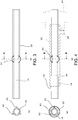
- FIG. 3 shows a structure of the inner tube 20, where (a) is a front view and (b) is a cross sectional view along a line B-B.
- FIG. 4 shows a structure in which the outer tube 22 is placed at an outer side of the inner tube 20, where (a) is a front view (showing the outer tube 22 with a two-dots-and-chain line), and (b) is a cross sectional view along a line B-B.
- a spacer 50 of a plate shape which has a predetermined length in the tube axis direction and which extends toward an outer side in the radial direction.
- three spacers 50 are placed on the outer circumferential surface of the inner tube 20 at equal intervals.
- a cross section of the spacer 50 passing through the tube axis has a trapezoid shape, an inner end of the spacer 50 is fixed on the outer circumferential surface of the inner tube 20, and an outer end of the spacer 50 is in contact with the inner circumferential surface of the outer tube 22.
- the spacer 50 When a position of placement of the spacer 50 is near the rear end of the outer tube 22, the effect of maintaining the space is small, and when the position of placement is near the ejection port 30, the spacer 50 may affect the flow of the fluid effused from the ejection port 30. Therefore, the spacer 50 is desirably placed near an approximate center of the inner tube 20 in the length direction.
- the number of the spacers 50 may be two or more, but when the number is too large, the cross section of the annular flow path 18 becomes small. Therefore, an appropriate number of the spacers 50 is about 3.
- a material which elastically deforms may be desirably employed, such as a plastic.
- a concave groove for housing the outer end of the spacer 50 may be provided on the inner circumferential surface of the outer tube 22.
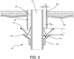
- FIG. 5 is an explanatory diagram of a flow of fluid from the ejection port 30.
- the trocar 10 is inserted in a manner to penetrate through the body wall, and a front end side thereof reaches an inside of the body cavity.
- a peritoneum 52 is an inner wall of a body cavity, and fluid (perfusion solution) is filled in the body cavity.
- the fluid from the annular flow path 18 is effused from the entirety of the annular ejection port 30 toward the front side in the tube axis direction.
- the concave surface 46 is formed on the upper surface (surface opposing the ejection port 30) of the saucer portion 44 of the flow control member 40. Therefore, the fluid effused from the ejection port 30 moves toward the front side in the tube axis direction, as shown by an arrow in FIG. 5 , hits the concave surface 46 of the saucer portion 44 of the flow control member 40, where the direction of the flow thereof is changed, and flows in a radiating direction toward a slanted upward direction.
- the outer end of the saucer portion 44 is set at an side that is further out in the radial direction than the inner circumference of the outer tube 22. Therefore, it is possible to prevent the flow of the fluid, effused in the tube axis direction from the ejection port 30 of the annular flow path 18, from directly flowing in the tube axis direction. Because the flow of the fluid effused from the ejection port 30 contacts the fluid at the periphery, the flow is disturbed. Thus, when the outer end of the saucer portion 44 is set to be equal to or smaller than the inner size of the outer tube 22, the flow in the tube axis direction cannot be effectively prevented.
- the outer size of the saucer portion 44 is set greater than the inner size of the outer tube 22, so that the flow in the tube axis direction can be effectively prevented, and even when a fluid is to flow with a high flow rate, the fluid flow toward the area of surgery can be blocked and can be moved away.
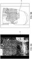
- FIG. 6A is a photograph of a state in which water is filled in a beaker, the trocar 10 is inserted into the water, and a fluid including an ink is effused.
- FIG. 6B is a diagram schematically showing a spreading state of the fluid including the ink. As shown, it can be understood that by changing the flow of the fluid moving in the tube axis direction to a slanted upward direction with the flow control member 40, the disturbance of the fluid flow can be prevented at the area of surgery at a lower side of the flow control member 40.
- the outer size of the flow control member 40 is set greater than the outer size of the outer tube 22, but the outer size of the flow control member 40 may alternatively be smaller than the outer size of the outer tube 22 so long as the outer size of the flow control member 40 is greater than the inner size of the outer tube 22 (that is, the outer size of the ejection port 30). That is, b in FIG. 5 may be set to between 0 and a few mm.
- a relative position in the tube axis direction of the outer tube 22 with respect to the inner tube 20 may be set adjustable so that the position of the flow control member 40 in the tube axis direction is adjustable, to enable adjustment of a distance c in FIG. 5 , between the ejection port 30 and the flow control member 40.
- the distance c may be set to a few mm. In this manner, the distance may be determined based on the use.
- FIG. 7 shows an example configuration in which a female screw portion 24a is provided on an inner wall of a gripping portion 24, and a male screw portion 20b is provided at a corresponding position on an outer circumference of the inner tube 20.
- the inner tube 20 may be rotated with respect to the gripping portion 24, to move the inner tube 20 in a front and rear direction in the tube axis direction, and a distance between the flow control member 40 fixed on the inner tube 20 and the ejection port 30 can thereby be adjusted.
- FIG. 8 shows another example configuration for the gripping portion 24 and the outer circumference of the inner tube 20.
- a protrusion 24b having a semicircular cross section and protruding toward an inner side in the radial direction is provided on the inner wall of the gripping portion 24, and a recess 20c of a corresponding shape is provided on the outer circumference of the inner tube 20.
- the inner tube 20 may be moved in the front-and-rear direction in the tube axis direction so that the position of the inner tube 20 with respect to the outer tube 22 can be changed, and a distance between the ejection port 30 and the flow control member 40 fixed on the inner tube 20 can thereby be adjusted.
- FIG. 9 shows another example configuration of the flow control member 40.
- a flat surface portion 46a which is orthogonal to the tube axis is provided at an inner portion (side closer to the inner tube 20) of the concave surface 46 of the saucer portion 44 formed on the upper surface (surface opposing the ejection port 30) of the flow control member 40, and an inclined surface in a slanted upward direction is provided at an outer circumferential side of the flat surface portion 46a.
- FIG. 10 shows yet another example configuration of the flow control member 40.
- the flow control member 40 is formed from a plurality of (multiple) petal shaped members 60. Specifically, an upper surface of the petal shaped member 60 from a center part in a slanted upward direction forms the saucer portion 44. With such a configuration, the petal shaped member 60 may be opened and closed. Thus, the petal shaped member 60 may be closed when the trocar 10 is inserted into or removed from the body cavity.
- a suitable structure may be employed for the opening and closing of the petal shaped member 60.
- the petal shaped member 60 may be opened and closed by fixing the flow control member 40 on the outer tube 22 at a position a predetermined distance apart from the ejection port 30, and moving the inner tube 20 in the front and in the rear in the tube axis direction.
- the movement of the inner tube 20 in the tube axis direction may be realized by driving with a motor or the like.
- FIG. 11 shows another example configuration of the flow control member 40.
- the flow control member 40 has an umbrella shape. Similar to the above, with this configuration also, the flow control member 40 may be opened and closed.
- the outer size of the flow control member 40 is approximately equal to the outer size of the outer tube 22. Therefore, the trocar 10 can be easily inserted into the body cavity without changing the manipulations of the related art. Because the fluid flowing into the abdominal cavity does not directly reach the area of surgery, a continuous perfusion may be performed while maintaining the field of view.
- a flow close to a stable laminar flow may be created near the area of surgery, diffusion of bleeding during the surgery under the fluid (perfusion solution) can be prevented, and the field of view can continue to be secured.
- the outer size of the trocar 10 is desirably set to a diameter of 12 ⁇ 15 mm, which is equivalent to the outer size of a typical trocar. With such a configuration, an invasiveness similar to the trocar of the related art can be maintained.
- the space between the outer tube 22 and the inner tube 20 is desirably about 1 mm.
- the outer size of the inner tube 20 of the trocar 10 used in the experiment was 9.5 mm, the inner size of the outer tube 22 was 12 mm, and the width of the annular flow path 18 was 1.25 mm.
- a velocity of the fluid flow of the fluid effused from the ejection port 30 was set to approximately 300 ml/min. ⁇ 1000 ml/min.
- the concave surface 46 was employed for the upper surface of the saucer portion 44 of the flow control member 40 in order to change the direction of the fluid flow
- the outer size was set to equivalent to or greater than the outer size of the outer tube 22.
- an angle ⁇ of the inclined surface in the saucer portion 44 with respect to the tube axis direction was about 60 degrees, and was desirably in a range of 75 degrees ⁇ 45 degrees.
- a perfusion experiment simulating bleeding from a rear surface of a pubic bone was performed.
- the cow blood supplied from the trocar 10 flowed toward a suctioning cannula which was separately provided, and there was no blocking of the field of view due to the diffusion of the blood.
Landscapes
- Health & Medical Sciences (AREA)
- Heart & Thoracic Surgery (AREA)
- Life Sciences & Earth Sciences (AREA)
- General Health & Medical Sciences (AREA)
- Veterinary Medicine (AREA)
- Biomedical Technology (AREA)
- Public Health (AREA)
- Animal Behavior & Ethology (AREA)
- Engineering & Computer Science (AREA)
- Anesthesiology (AREA)
- Hematology (AREA)
- Surgery (AREA)
- Pulmonology (AREA)
- Pathology (AREA)
- Nuclear Medicine, Radiotherapy & Molecular Imaging (AREA)
- Medical Informatics (AREA)
- Molecular Biology (AREA)
- Endoscopes (AREA)
- Surgical Instruments (AREA)
Abstract
Description
- The present disclosure relates to a trocar which is used by inserting a tip side thereof into a body cavity of a patient.
- Some surgeries are performed with equipment such as an endoscope (surgical equipment or surgical instrument) being inserted into a body cavity of a patient. In this case, a trocar is used as a guiding tube for the equipment to be inserted.
- A trocar with a perfusion function of the related art described in Patent Literature 1 has a structure in which an access port, a water injection port, and a water absorption port of the equipment are integrated. For example, in surgery which is performed in a manner similar to an in-water endoscopic surgery, three functions are provided to the port, so as to realize suppression of a number of incisional wounds. In addition, a cross sectional area of a tip opening of the water absorption port is an area greater than or equal to five times a cross sectional area of an opening on an ejection side, so that a flow rate at the outflow side is fast, and contamination such as blood in a surgical field (an area of surgery) can thereby be effectively removed.
- Patent Literature 2 discloses a body wall contact type water tank having functions of a fluid flow entrance to both the incisional wound and the body cavity, in a surgical form such as the in-water endoscopic surgery described above. In this example structure, because there is a storage space for fluid outside of the body cavity and a body cavity flow entrance of the fluid is relatively wide, diffusion of bleeding of the like, which occurs in the body cavity, in the fluid can be suppressed, and a new perfusion solution can be continuously supplied.
-
Patent Literature 3 discloses surgical equipment in which an injection direction when the perfusion solution is injected into the body cavity is changed to a direction at a right angle to a tube axis of the trocar, so as to avoid direct flow of a jet to the area of surgery. In other words, a collar element is provided opposing an ejection port, and the direction of the flow is changed by the collar element. -
- Patent Literature 1:
JP 2012-81191 A - Patent Literature 2:
JP 2014-61132 A - Patent Literature 3:
JP 2018-86168 A - In Patent Literature 1, because the flow rate at an opening on the ejection side is relatively fast, when, for example, a body cavity which is a surgical target is wide and an amount of contamination included in the perfusion solution in the area of surgery is large, the contamination diffuses throughout a wide range in the area of surgery, and thus, a field of view in the area of surgery tends to be easily blocked.
- In Patent Literature 2, because a water tank is provided, a relatively large incisional wound is necessary. In addition, with in-water endoscopic surgery, a surgical instrument for the endoscopic surgery may be used, but when the surgical instrument is inserted into a wide opening, it may be difficult to fix a fulcrum of the equipment.
- In
Patent Literature 3, when a large amount of perfusion solution is used, the flow rate becomes fast, and the flow direction cannot be sufficiently controlled. In particular, because a diameter of the collar element is set smaller than an inner size of an outer tube in order to maintain an abdominal wall penetration capability (an ability of penetrating an abdominal wall) of the trocar, there may be cases in which the flow direction control cannot be sufficiently performed. - An advantage of the present disclosure lies in improvement of controllability of the flow of fluid to be supplied with the trocar.
- According to one aspect of the present disclosure, there is provided a trocar which is used by a tip side thereof being inserted into a body cavity of a patient, the trocar comprising: an inner tube that has a center duct line; an outer tube that is placed covering an outer circumference of the inner tube and in which a front end is positioned in the rear of a front end of the inner tube; a flow path that is formed between the inner tube and the outer tube, and that has an ejection port at a position of the front end of the outer tube; and a flow control member that is provided at a position in front of the front end of the outer tube and opposing the ejection port, wherein the flow control member has an inclined surface which is slanted rearward toward an outer side in a radial direction.
- In another configuration, the flow control member may have a concave surface at a portion opposing the ejection port.
- In another configuration, an outer size of the flow control member may be greater than an outer size of the ejection port.
- In another configuration, the flow path may be an annular flow path, and the ejection port may be an annular ejection port.
- In another configuration, the flow control member may have a cone shape which widens from an entirety of the outer circumference of the inner tube toward an outer side in the radial direction and in a slanted rearward direction, so that a concave surface is formed on an upper surface of the flow control member.
- In another configuration, a spacer may be provided between an outer circumference of the inner tube and an inner circumference of the outer tube, which maintains a spacing between the outer circumference of the inner tube and the inner circumference of the outer tube.
- In another configuration, a plurality of the spacers may be provided in an equal interval in an outer circumferential direction of the inner tube.
- Definition of the terms used in the present specification and in the claims are as follows.
- A "tube axis" is an axis which is a center line of the inner tube and the outer tube.
- A "in front of' is a front side on the tube axis, and is a direction of a forward movement of the trocar when the trocar is inserted into the body cavity along the tube axis.
- A "in the rear of' is a rear side on the tube axis, and is a direction of a backward movement of the trocar along the tube axis.
- A "front end" is an end at the front side.
- A "rear end" is an end at the rear side.
- An "upper surface" is a surface which opposes the ejection port.
- A "radial direction" is a direction of a line segment drawn from the tube axis of the inner tube and the outer tube, orthogonal to the circumferences thereof.
- According to the present disclosure, a flow of the fluid effused from the ejection port may be controlled and may be effectively moved away from the area of surgery.
-
-
FIG. 1 is a diagram showing an outer appearance of a structure of a trocar according to an embodiment of the present disclosure. -
FIG. 2 is a diagram showing a cross section of the trocar ofFIG. 1 , in the tube axis direction. -
FIG. 3 is a diagram showing a structure of an inner tube, where (a) is a front view, and (b) is a cross sectional view along a line B-B. -
FIG. 4 is a diagram showing a structure in which anouter tube 22 is placed at an outer side of the inner tube, where (a) is a front view (with the outer tube shown with two-dots-and-chain line), and (b) is a cross sectional view along a line B-B. -
FIG. 5 is an explanatory diagram of a flow of fluid from an ejection port. -
FIG. 6A is a photograph showing a state in which water is filled in a beaker, a trocar is inserted in the water, and a fluid including an ink is effused. -
FIG. 6B is a diagram schematically showing the photograph ofFIG. 6A . -
FIG. 7 is a diagram showing an example configuration in which a female screw portion is provided on an inner wall of a gripping portion, and a male screw portion is provided at a corresponding position at a periphery of the inner tube. -
FIG. 8 is a diagram showing an example configuration in which a projection is provided on an inner wall of the gripping portion, and a concave is provided at a corresponding position at a periphery of the inner tube. -
FIG. 9 is a diagram showing another example structure (structure with a flat surface portion) of a flow control member. -
FIG. 10 is a diagram showing another example structure (petal shape) of the flow control member. -
FIG. 11 is a diagram showing another example structure (umbrella shape) of the flow control member. - An embodiment of the present disclosure will now be described with reference to the drawings. The present disclosure is not limited to the embodiment described herein.
-
FIG. 1 shows an outer appearance of a structure of atrocar 10 according to the present embodiment, andFIG. 2 is a cross sectional diagram in a tube axis direction. - The
trocar 10 has a double tube structure in which two circular cylindrical tubes are placed concentrically, and has acenter duct line 16, and anannular flow path 18. Thecenter duct line 16 is a hollow duct line inside aninner tube 20, penetrates through the entirety of theinner tube 20, and has respective ends opened. Thus, thecenter duct line 16 is used as a passage for inserting and removing a surgical device such as an endoscope. On thecenter duct line 16, avalve 20a is placed, so as to prevent flowing out of fluid from a rear end of thecenter duct line 16 to the outside, while enabling insertion and removal of the surgical device. - A length of an
outer tube 22 is shorter than theinner tube 20, and both a front end and a rear end thereof are positioned at a side that is further inward than respective ends of theinner tube 20. Theannular flow path 18 is formed with a vacant space between an inner circumferential surface of theouter tube 22 and an outer circumferential surface of theinner tube 20. Theannular flow path 18 has the front end opened, but the rear end of theouter tube 22 extends to an outer circumference of theinner tube 20 to close theannular flow path 18. In this example configuration, theinner tube 20 can move with respect to theouter tube 22 in the tube axis direction, and avalve 22a is placed at the rear end of theouter tube 22 to close the rear end of theannular flow path 18. Theannular flow path 18 does not need to have a perfect annular shape. - A gripping
portion 24 is provided, covering an outer side of a rear portion of theouter tube 22. A front end of the grippingportion 24 is fixed on an outer circumference of theouter tube 22, and a hole passing through theinner tube 20 is provided at a rear end of the grippingportion 24. That is, theinner tube 20 penetrates through the rear end of the grippingportion 24, and can move with respect to the grippingportion 24 ion the tube axis direction. - At a position on the
outer tube 22 near the grippingportion 24, afluid inflow tube 26 which is in communication with theannular flow path 18 is placed toward an outer side in a radial direction. A fluid is supplied from thefluid inflow tube 26 toward theannular flow path 18. - The front end of the
annular flow path 18 ends at a rear side of the front end of theinner tube 20, to form anejection port 30 which is opened and which has an annular shape. In other words, theannular ejection port 30 is formed at a front end position of theouter tube 22. The fluid (perfusion solution) to be supplied to theannular flow path 18 is effused from theejection port 30. - At a position at a front side of the
ejection port 30 and opposing theejection port 30, aflow control member 40 is placed. Theflow control member 40 has a base 42 having a circular cylindrical shape, and asaucer portion 44 having a cone shape (an inverted circular cone trapezium shape) which widens from an upper end (rear side) of the base 42 toward an outer side in the radial direction and toward a slanted rearward direction. An upper surface (surface opposing the ejection port 30) of thesaucer portion 44 is aconcave surface 46. Thebase 42 is attached on the outer circumference of theinner tube 20, and at a position which is a predetermined distance in front from theejection port 30. Because of this structure, the fluid effused from theejection port 30 hits the concave surfaced 46 of theflow control member 40, and the direction of the flow thereof is changed. - The perfusion solution is suctioned from a suctioning cannula placed at a periphery of a surgical site so that a pressure at the periphery is maintained at a desired pressure.
- The
inner tube 20, theouter tube 22, the grippingportion 24, and the like are desirably formed from a plastic such as polycarbonate, but may alternatively be formed from a metal such as the stainless steel. Theflow control member 40 desirably has a certain degree of flexibility, and is desirably formed from a silicon resin, or other soft plastic materials. Thevalves -
FIG. 3 shows a structure of theinner tube 20, where (a) is a front view and (b) is a cross sectional view along a line B-B.FIG. 4 shows a structure in which theouter tube 22 is placed at an outer side of theinner tube 20, where (a) is a front view (showing theouter tube 22 with a two-dots-and-chain line), and (b) is a cross sectional view along a line B-B. - As shown, at an outer circumference of a middle portion of the
inner tube 20 in the tube axis direction, aspacer 50 of a plate shape is provided, which has a predetermined length in the tube axis direction and which extends toward an outer side in the radial direction. In the illustrated example configuration, threespacers 50 are placed on the outer circumferential surface of theinner tube 20 at equal intervals. A cross section of thespacer 50 passing through the tube axis has a trapezoid shape, an inner end of thespacer 50 is fixed on the outer circumferential surface of theinner tube 20, and an outer end of thespacer 50 is in contact with the inner circumferential surface of theouter tube 22. By placing such aspacer 50, theannular flow path 18 in the space between theinner tube 20 and theouter tube 22 can be maintained, and an orientation of thetrocar 10 can be stabilized. - When a position of placement of the
spacer 50 is near the rear end of theouter tube 22, the effect of maintaining the space is small, and when the position of placement is near theejection port 30, thespacer 50 may affect the flow of the fluid effused from theejection port 30. Therefore, thespacer 50 is desirably placed near an approximate center of theinner tube 20 in the length direction. The number of thespacers 50 may be two or more, but when the number is too large, the cross section of theannular flow path 18 becomes small. Therefore, an appropriate number of thespacers 50 is about 3. - For the
spacer 50, a material which elastically deforms may be desirably employed, such as a plastic. Further, a concave groove for housing the outer end of thespacer 50 may be provided on the inner circumferential surface of theouter tube 22. -
FIG. 5 is an explanatory diagram of a flow of fluid from theejection port 30. Thetrocar 10 is inserted in a manner to penetrate through the body wall, and a front end side thereof reaches an inside of the body cavity. For example, aperitoneum 52 is an inner wall of a body cavity, and fluid (perfusion solution) is filled in the body cavity. - The fluid from the
annular flow path 18 is effused from the entirety of theannular ejection port 30 toward the front side in the tube axis direction. On the upper surface (surface opposing the ejection port 30) of thesaucer portion 44 of theflow control member 40, theconcave surface 46 is formed. Therefore, the fluid effused from theejection port 30 moves toward the front side in the tube axis direction, as shown by an arrow inFIG. 5 , hits theconcave surface 46 of thesaucer portion 44 of theflow control member 40, where the direction of the flow thereof is changed, and flows in a radiating direction toward a slanted upward direction. In particular, the outer end of thesaucer portion 44 is set at an side that is further out in the radial direction than the inner circumference of theouter tube 22. Therefore, it is possible to prevent the flow of the fluid, effused in the tube axis direction from theejection port 30 of theannular flow path 18, from directly flowing in the tube axis direction. Because the flow of the fluid effused from theejection port 30 contacts the fluid at the periphery, the flow is disturbed. Thus, when the outer end of thesaucer portion 44 is set to be equal to or smaller than the inner size of theouter tube 22, the flow in the tube axis direction cannot be effectively prevented. In the present embodiment, the outer size of thesaucer portion 44 is set greater than the inner size of theouter tube 22, so that the flow in the tube axis direction can be effectively prevented, and even when a fluid is to flow with a high flow rate, the fluid flow toward the area of surgery can be blocked and can be moved away. -
FIG. 6A is a photograph of a state in which water is filled in a beaker, thetrocar 10 is inserted into the water, and a fluid including an ink is effused.FIG. 6B is a diagram schematically showing a spreading state of the fluid including the ink. As shown, it can be understood that by changing the flow of the fluid moving in the tube axis direction to a slanted upward direction with theflow control member 40, the disturbance of the fluid flow can be prevented at the area of surgery at a lower side of theflow control member 40. - In the present embodiment, the outer size of the
flow control member 40 is set greater than the outer size of theouter tube 22, but the outer size of theflow control member 40 may alternatively be smaller than the outer size of theouter tube 22 so long as the outer size of theflow control member 40 is greater than the inner size of the outer tube 22 (that is, the outer size of the ejection port 30). That is, b inFIG. 5 may be set to between 0 and a few mm. - A relative position in the tube axis direction of the
outer tube 22 with respect to theinner tube 20 may be set adjustable so that the position of theflow control member 40 in the tube axis direction is adjustable, to enable adjustment of a distance c inFIG. 5 , between theejection port 30 and theflow control member 40. For example, the distance c may be set to a few mm. In this manner, the distance may be determined based on the use. -
FIG. 7 shows an example configuration in which afemale screw portion 24a is provided on an inner wall of a grippingportion 24, and amale screw portion 20b is provided at a corresponding position on an outer circumference of theinner tube 20. With such a structure, theinner tube 20 may be rotated with respect to the grippingportion 24, to move theinner tube 20 in a front and rear direction in the tube axis direction, and a distance between theflow control member 40 fixed on theinner tube 20 and theejection port 30 can thereby be adjusted. -
FIG. 8 shows another example configuration for the grippingportion 24 and the outer circumference of theinner tube 20. In this example configuration, aprotrusion 24b having a semicircular cross section and protruding toward an inner side in the radial direction is provided on the inner wall of the grippingportion 24, and arecess 20c of a corresponding shape is provided on the outer circumference of theinner tube 20. With such a configuration, theinner tube 20 may be moved in the front-and-rear direction in the tube axis direction so that the position of theinner tube 20 with respect to theouter tube 22 can be changed, and a distance between theejection port 30 and theflow control member 40 fixed on theinner tube 20 can thereby be adjusted. -
FIG. 9 shows another example configuration of theflow control member 40. In this example configuration, aflat surface portion 46a which is orthogonal to the tube axis is provided at an inner portion (side closer to the inner tube 20) of theconcave surface 46 of thesaucer portion 44 formed on the upper surface (surface opposing the ejection port 30) of theflow control member 40, and an inclined surface in a slanted upward direction is provided at an outer circumferential side of theflat surface portion 46a. With such a structure, the flow in the tube axis direction of the fluid effused from theejection port 30 can be received, and the direction of this flow may be changed to a lateral direction (radial direction). -
FIG. 10 shows yet another example configuration of theflow control member 40. In this example configuration, theflow control member 40 is formed from a plurality of (multiple) petal shapedmembers 60. Specifically, an upper surface of the petal shapedmember 60 from a center part in a slanted upward direction forms thesaucer portion 44. With such a configuration, the petal shapedmember 60 may be opened and closed. Thus, the petal shapedmember 60 may be closed when thetrocar 10 is inserted into or removed from the body cavity. For the opening and closing of the petal shapedmember 60, a suitable structure may be employed. For example, the petal shapedmember 60 may be opened and closed by fixing theflow control member 40 on theouter tube 22 at a position a predetermined distance apart from theejection port 30, and moving theinner tube 20 in the front and in the rear in the tube axis direction. Alternatively, the movement of theinner tube 20 in the tube axis direction may be realized by driving with a motor or the like. -
FIG. 11 shows another example configuration of theflow control member 40. In this example configuration, theflow control member 40 has an umbrella shape. Similar to the above, with this configuration also, theflow control member 40 may be opened and closed. - According to the
trocar 10 of the present embodiment, the outer size of theflow control member 40 is approximately equal to the outer size of theouter tube 22. Therefore, thetrocar 10 can be easily inserted into the body cavity without changing the manipulations of the related art. Because the fluid flowing into the abdominal cavity does not directly reach the area of surgery, a continuous perfusion may be performed while maintaining the field of view. - That is, with the
trocar 10 of the present embodiment, a flow close to a stable laminar flow may be created near the area of surgery, diffusion of bleeding during the surgery under the fluid (perfusion solution) can be prevented, and the field of view can continue to be secured. - Specific specifications will now be described.
- The outer size of the
trocar 10 is desirably set to a diameter of 12 ∼ 15 mm, which is equivalent to the outer size of a typical trocar. With such a configuration, an invasiveness similar to the trocar of the related art can be maintained. - As a result of a simulation by a computer and an experiment with a prototype, it was found that the space between the
outer tube 22 and the inner tube 20 (width of theannular flow path 18, "a" inFIG. 5 ) is desirably about 1 mm. The outer size of theinner tube 20 of thetrocar 10 used in the experiment was 9.5 mm, the inner size of theouter tube 22 was 12 mm, and the width of theannular flow path 18 was 1.25 mm. - A velocity of the fluid flow of the fluid effused from the ejection port 30 (perfusion solution) was set to approximately 300 ml/min. ∼ 1000 ml/min., the
concave surface 46 was employed for the upper surface of thesaucer portion 44 of theflow control member 40 in order to change the direction of the fluid flow, and the outer size was set to equivalent to or greater than the outer size of theouter tube 22. - Further, an angle θ of the inclined surface in the
saucer portion 44 with respect to the tube axis direction was about 60 degrees, and was desirably in a range of 75 degrees ∼ 45 degrees. - Using a cray model of an inside of a pelvis and cow blood, a perfusion experiment simulating bleeding from a rear surface of a pubic bone was performed. The cow blood supplied from the
trocar 10 flowed toward a suctioning cannula which was separately provided, and there was no blocking of the field of view due to the diffusion of the blood. - 10 TROCAR; 16 CENTER DUCT LINE; 18 ANNULAR FLOW PATH; 20 INNER TUBE; 22 OUTER TUBE; 26 FLUID INFLOW TUBE; 30 EJECTION PORT; 40 FLOW CONTROL MEMBER; 42 BASE; 44 SAUCER PORTION; 46 CONCAVE SURFACE; 50 SPACER; 60 PETAL SHAPED MEMBER.
Claims (7)
- A trocar which is used by a tip side thereof being inserted into a body cavity of a patient, the trocar comprising:an inner tube that has a center duct line;an outer tube that is placed covering an outer circumference of the inner tube and in which a front end is positioned in the rear of a front end of the inner tube;a flow path that is formed between the inner tube and the outer tube, and that has an ejection port at a position of the front end of the outer tube; anda flow control member that is provided at a position in front of the front end of the outer tube and opposing the ejection port, whereinthe flow control member has an inclined surface which is slanted rearward toward an outer side in a radial direction.
- The trocar according to claim 1, wherein
the flow control member has a concave surface at a portion opposing the ejection port. - The trocar according to claim 2, wherein
an outer size of the flow control member is greater than an outer size of the ejection port. - The trocar according to any one of claims 1 to 3, wherein
the flow path is an annular flow path, and the ejection port is an annular ejection port. - The trocar according to any one of claims 1 to 4, wherein
the flow control member has a cone shape which widens from an entirety of an outer circumference of the inner tube toward an outer side in the radial direction and in a slanted rearward direction, so that a concave surface is formed on an upper surface of the flow control member. - The trocar according to any one of claims 1 to 5, wherein
a spacer is provided between an outer circumference of the inner tube and an inner circumference of the outer tube, which maintains a spacing between the outer circumference of the inner tube and the inner circumference of the outer tube. - The trocar according to claim 6, wherein
a plurality of the spacers are provided at equal intervals in an outer circumferential direction of the inner tube.
Applications Claiming Priority (2)
| Application Number | Priority Date | Filing Date | Title |
|---|---|---|---|
| JP2018216694A JP7078522B2 (en) | 2018-11-19 | 2018-11-19 | Trocar |
| PCT/JP2019/044595 WO2020105528A1 (en) | 2018-11-19 | 2019-11-13 | Trocar |
Publications (2)
| Publication Number | Publication Date |
|---|---|
| EP3865043A1 true EP3865043A1 (en) | 2021-08-18 |
| EP3865043A4 EP3865043A4 (en) | 2022-02-09 |
Family
ID=70774536
Family Applications (1)
| Application Number | Title | Priority Date | Filing Date |
|---|---|---|---|
| EP19886486.0A Withdrawn EP3865043A4 (en) | 2018-11-19 | 2019-11-13 | TROCAR |
Country Status (5)
| Country | Link |
|---|---|
| US (1) | US20220008644A1 (en) |
| EP (1) | EP3865043A4 (en) |
| JP (1) | JP7078522B2 (en) |
| CN (1) | CN113015475A (en) |
| WO (1) | WO2020105528A1 (en) |
Families Citing this family (1)
| Publication number | Priority date | Publication date | Assignee | Title |
|---|---|---|---|---|
| WO2024134602A1 (en) * | 2022-12-23 | 2024-06-27 | Fisher & Paykel Healthcare Limited | Cannula |
Family Cites Families (12)
| Publication number | Priority date | Publication date | Assignee | Title |
|---|---|---|---|---|
| SU1437455A1 (en) * | 1987-03-23 | 1988-11-15 | Хабаровский политехнический институт | Fluid flowrate stabilizer |
| DK199900539A (en) * | 1999-04-21 | 2000-10-22 | Bisgaard Therkel | Expandable Trocar |
| US7435214B2 (en) * | 2004-01-29 | 2008-10-14 | Cannuflow, Inc. | Atraumatic arthroscopic instrument sheath |
| WO2005072402A2 (en) * | 2004-01-29 | 2005-08-11 | Cannuflow, Inc. | Atraumatic arthroscopic instrument sheath |
| JP5331318B2 (en) * | 2007-08-09 | 2013-10-30 | オリンパス株式会社 | Endoscope device |
| EP2608724A4 (en) * | 2010-08-25 | 2014-04-23 | Cardiapex Ltd | Minimally invasive surgical techniques |
| JP5554203B2 (en) | 2010-10-14 | 2014-07-23 | 日機装株式会社 | Trocar |
| CN102489093A (en) * | 2011-12-27 | 2012-06-13 | 刘永宝 | Water curtain injector |
| JP5504316B2 (en) | 2012-09-21 | 2014-05-28 | 日機装株式会社 | Body wall contact water tank and body cavity fluid perfusion system |
| JP2015208549A (en) * | 2014-04-28 | 2015-11-24 | オリンパス株式会社 | Trocar |
| JP6622175B2 (en) * | 2016-11-29 | 2019-12-18 | 国立大学法人千葉大学 | Trocar |
| CN106618451A (en) * | 2016-12-06 | 2017-05-10 | 广州瑞达医疗器械有限公司 | Endoscope sheath |
-
2018
- 2018-11-19 JP JP2018216694A patent/JP7078522B2/en active Active
-
2019
- 2019-11-13 WO PCT/JP2019/044595 patent/WO2020105528A1/en not_active Ceased
- 2019-11-13 EP EP19886486.0A patent/EP3865043A4/en not_active Withdrawn
- 2019-11-13 US US17/293,811 patent/US20220008644A1/en not_active Abandoned
- 2019-11-13 CN CN201980074398.4A patent/CN113015475A/en active Pending
Also Published As
| Publication number | Publication date |
|---|---|
| WO2020105528A1 (en) | 2020-05-28 |
| JP2020081090A (en) | 2020-06-04 |
| JP7078522B2 (en) | 2022-05-31 |
| CN113015475A (en) | 2021-06-22 |
| US20220008644A1 (en) | 2022-01-13 |
| EP3865043A4 (en) | 2022-02-09 |
Similar Documents
| Publication | Publication Date | Title |
|---|---|---|
| ES2708204T3 (en) | Catheter adapter with port that has a combined port and a vented blood control valve | |
| ES2863967T3 (en) | First-entry trocar system | |
| EP2155083B1 (en) | Seal assembly for a cannula | |
| JP4820703B2 (en) | Liquid infusion tool | |
| ES2769810T3 (en) | Optical trocar system | |
| KR100731429B1 (en) | A three-way valve and a transfusion circuit or a transfusion circuit using the three-way valve | |
| JP5943922B2 (en) | Catheter assembly | |
| ES2876945T3 (en) | Catheter assembly system | |
| JP6401906B2 (en) | System and method for providing a catheter assembly | |
| ES2824845T3 (en) | Perforated septum valve and catheter assembly | |
| ES2541703T3 (en) | Systems and methods to provide a flow control valve for a medical device | |
| ES2736960T3 (en) | Multi-purpose blood control valve with central and circumferential cuts | |
| BR112014008349B1 (en) | INTRAVENOUS CATHETER SET | |
| US20030050603A1 (en) | Cannula that provides bi-directional fluid flow that is regulated by a single valve | |
| US9526828B2 (en) | Flow-controlling catheter hub | |
| JP6351591B2 (en) | Medical insertion aid | |
| BR112013001047B1 (en) | SYSTEM TO CONTROL A FLUID FLOW IN A CLOSED CATHETER IV ASSEMBLY | |
| EP1032454A1 (en) | Device for subcutaneous accessibility | |
| US20220008644A1 (en) | Trocar | |
| JP5930481B2 (en) | Connector assembly and male connector | |
| JP6889820B2 (en) | Indwelling needle assembly | |
| JP2018086168A (en) | Trocar | |
| ES2834969T3 (en) | Multipurpose Blood Monitoring Safety Catheter Assembly | |
| KR20240047032A (en) | Duckbill type catheter unit for intraperitoneal ascites drain | |
| JP2024020810A (en) | needle assembly |
Legal Events
| Date | Code | Title | Description |
|---|---|---|---|
| STAA | Information on the status of an ep patent application or granted ep patent |
Free format text: STATUS: THE INTERNATIONAL PUBLICATION HAS BEEN MADE |
|
| PUAI | Public reference made under article 153(3) epc to a published international application that has entered the european phase |
Free format text: ORIGINAL CODE: 0009012 |
|
| STAA | Information on the status of an ep patent application or granted ep patent |
Free format text: STATUS: REQUEST FOR EXAMINATION WAS MADE |
|
| 17P | Request for examination filed |
Effective date: 20210512 |
|
| AK | Designated contracting states |
Kind code of ref document: A1 Designated state(s): AL AT BE BG CH CY CZ DE DK EE ES FI FR GB GR HR HU IE IS IT LI LT LU LV MC MK MT NL NO PL PT RO RS SE SI SK SM TR |
|
| REG | Reference to a national code |
Ref country code: DE Ref legal event code: R079 Free format text: PREVIOUS MAIN CLASS: A61B0001000000 Ipc: A61B0017340000 |
|
| A4 | Supplementary search report drawn up and despatched |
Effective date: 20220110 |
|
| RIC1 | Information provided on ipc code assigned before grant |
Ipc: A61B 17/00 20060101ALN20220103BHEP Ipc: A61B 17/34 20060101AFI20220103BHEP |
|
| DAV | Request for validation of the european patent (deleted) | ||
| DAX | Request for extension of the european patent (deleted) | ||
| STAA | Information on the status of an ep patent application or granted ep patent |
Free format text: STATUS: THE APPLICATION IS DEEMED TO BE WITHDRAWN |
|
| 18D | Application deemed to be withdrawn |
Effective date: 20240601 |