EP3865003A1 - Slide rail assembly - Google Patents
Slide rail assembly Download PDFInfo
- Publication number
- EP3865003A1 EP3865003A1 EP20179445.0A EP20179445A EP3865003A1 EP 3865003 A1 EP3865003 A1 EP 3865003A1 EP 20179445 A EP20179445 A EP 20179445A EP 3865003 A1 EP3865003 A1 EP 3865003A1
- Authority
- EP
- European Patent Office
- Prior art keywords
- rail
- feature
- working member
- state
- contact
- Prior art date
- Legal status (The legal status is an assumption and is not a legal conclusion. Google has not performed a legal analysis and makes no representation as to the accuracy of the status listed.)
- Granted
Links
Images






Classifications
-
- A—HUMAN NECESSITIES
- A47—FURNITURE; DOMESTIC ARTICLES OR APPLIANCES; COFFEE MILLS; SPICE MILLS; SUCTION CLEANERS IN GENERAL
- A47B—TABLES; DESKS; OFFICE FURNITURE; CABINETS; DRAWERS; GENERAL DETAILS OF FURNITURE
- A47B88/00—Drawers for tables, cabinets or like furniture; Guides for drawers
- A47B88/40—Sliding drawers; Slides or guides therefor
- A47B88/403—Drawer slides being extractable on two or more sides of the cabinet
-
- A—HUMAN NECESSITIES
- A47—FURNITURE; DOMESTIC ARTICLES OR APPLIANCES; COFFEE MILLS; SPICE MILLS; SUCTION CLEANERS IN GENERAL
- A47B—TABLES; DESKS; OFFICE FURNITURE; CABINETS; DRAWERS; GENERAL DETAILS OF FURNITURE
- A47B88/00—Drawers for tables, cabinets or like furniture; Guides for drawers
- A47B88/40—Sliding drawers; Slides or guides therefor
- A47B88/423—Fastening devices for slides or guides
-
- A—HUMAN NECESSITIES
- A47—FURNITURE; DOMESTIC ARTICLES OR APPLIANCES; COFFEE MILLS; SPICE MILLS; SUCTION CLEANERS IN GENERAL
- A47B—TABLES; DESKS; OFFICE FURNITURE; CABINETS; DRAWERS; GENERAL DETAILS OF FURNITURE
- A47B88/00—Drawers for tables, cabinets or like furniture; Guides for drawers
- A47B88/40—Sliding drawers; Slides or guides therefor
- A47B88/49—Sliding drawers; Slides or guides therefor with double extensible guides or parts
- A47B88/493—Sliding drawers; Slides or guides therefor with double extensible guides or parts with rollers, ball bearings, wheels, or the like
-
- H—ELECTRICITY
- H05—ELECTRIC TECHNIQUES NOT OTHERWISE PROVIDED FOR
- H05K—PRINTED CIRCUITS; CASINGS OR CONSTRUCTIONAL DETAILS OF ELECTRIC APPARATUS; MANUFACTURE OF ASSEMBLAGES OF ELECTRICAL COMPONENTS
- H05K7/00—Constructional details common to different types of electric apparatus
- H05K7/14—Mounting supporting structure in casing or on frame or rack
- H05K7/1485—Servers; Data center rooms, e.g. 19-inch computer racks
- H05K7/1488—Cabinets therefor, e.g. chassis or racks or mechanical interfaces between blades and support structures
- H05K7/1489—Cabinets therefor, e.g. chassis or racks or mechanical interfaces between blades and support structures characterized by the mounting of blades therein, e.g. brackets, rails, trays
-
- A—HUMAN NECESSITIES
- A47—FURNITURE; DOMESTIC ARTICLES OR APPLIANCES; COFFEE MILLS; SPICE MILLS; SUCTION CLEANERS IN GENERAL
- A47B—TABLES; DESKS; OFFICE FURNITURE; CABINETS; DRAWERS; GENERAL DETAILS OF FURNITURE
- A47B88/00—Drawers for tables, cabinets or like furniture; Guides for drawers
- A47B88/40—Sliding drawers; Slides or guides therefor
- A47B88/423—Fastening devices for slides or guides
- A47B2088/4235—Fastening devices for slides or guides having a latch mechanism coupling or disconnecting a drawer with drawer side slide from the rest of the slide members
-
- A—HUMAN NECESSITIES
- A47—FURNITURE; DOMESTIC ARTICLES OR APPLIANCES; COFFEE MILLS; SPICE MILLS; SUCTION CLEANERS IN GENERAL
- A47B—TABLES; DESKS; OFFICE FURNITURE; CABINETS; DRAWERS; GENERAL DETAILS OF FURNITURE
- A47B2210/00—General construction of drawers, guides and guide devices
- A47B2210/0002—Guide construction for drawers
- A47B2210/0029—Guide bearing means
- A47B2210/0032—Balls
-
- A—HUMAN NECESSITIES
- A47—FURNITURE; DOMESTIC ARTICLES OR APPLIANCES; COFFEE MILLS; SPICE MILLS; SUCTION CLEANERS IN GENERAL
- A47B—TABLES; DESKS; OFFICE FURNITURE; CABINETS; DRAWERS; GENERAL DETAILS OF FURNITURE
- A47B2210/00—General construction of drawers, guides and guide devices
- A47B2210/0002—Guide construction for drawers
- A47B2210/0051—Guide position
- A47B2210/0059—Guide located at the side of the drawer
-
- A—HUMAN NECESSITIES
- A47—FURNITURE; DOMESTIC ARTICLES OR APPLIANCES; COFFEE MILLS; SPICE MILLS; SUCTION CLEANERS IN GENERAL
- A47B—TABLES; DESKS; OFFICE FURNITURE; CABINETS; DRAWERS; GENERAL DETAILS OF FURNITURE
- A47B2210/00—General construction of drawers, guides and guide devices
- A47B2210/0002—Guide construction for drawers
- A47B2210/0064—Guide sequencing or synchronisation
- A47B2210/007—Three slide synchronisation
-
- A—HUMAN NECESSITIES
- A47—FURNITURE; DOMESTIC ARTICLES OR APPLIANCES; COFFEE MILLS; SPICE MILLS; SUCTION CLEANERS IN GENERAL
- A47B—TABLES; DESKS; OFFICE FURNITURE; CABINETS; DRAWERS; GENERAL DETAILS OF FURNITURE
- A47B2210/00—General construction of drawers, guides and guide devices
- A47B2210/0002—Guide construction for drawers
- A47B2210/0064—Guide sequencing or synchronisation
- A47B2210/0081—Telescopic drawer rails with stop blocks, e.g. synchronization buffers
-
- A—HUMAN NECESSITIES
- A47—FURNITURE; DOMESTIC ARTICLES OR APPLIANCES; COFFEE MILLS; SPICE MILLS; SUCTION CLEANERS IN GENERAL
- A47B—TABLES; DESKS; OFFICE FURNITURE; CABINETS; DRAWERS; GENERAL DETAILS OF FURNITURE
- A47B88/00—Drawers for tables, cabinets or like furniture; Guides for drawers
- A47B88/50—Safety devices or the like for drawers
- A47B88/57—Safety devices or the like for drawers preventing complete withdrawal of the drawer
Definitions
- the present invention relates to a slide rail assembly and more particularly to one that allows opening in two directions, or a two-way slide rail assembly.
- FIG. 1 to FIG. 4 of US Patent No. 5,871,265 disclose a conventional two-way slide assembly that includes an outer slide member, an inner slide member, and an intermediate slide member mounted between the outer slide member and the inner slide member.
- the arm at one end of the intermediate slide member is provided with two end stops, and the intermediate slide member is prevented from traveling in a certain direction when one of the two end stops contacts the inner slide member.
- the slide members take up a considerable amount of space when mounted between a drawer and a cabinet body and may therefore have a negative effect on the storage capacity of the drawer.
- FIG. 5 to FIG. 12 of the afore-cited US patent discloses a sequencing latch for preventing the intermediate slide member of a drawer slide assembly from protruding from either end of a two-way cabinet (or rack).
- the cams on the inner slide member apply a force to a latching arm on the intermediate slide member until the latching arm pivots through an aperture in the intermediate slide member and engages with a receptacle of the outer slide member.
- the latching mechanism of the sequencing latch shortens the distance for which the intermediate slide member can be displaced, making it relatively inconvenient for a user to access the objects in the drawer.
- the present invention relates to a slide rail assembly that allows opening in two directions and whose design has no negative effect on the distance for which each movable rail of the assembly can be displaced.
- a slide rail assembly includes a first rail, a second rail, a third rail, a first auxiliary structure, a first working member, and a first contact feature.
- the second rail can be displaced with respect to the first rail, and the third rail with respect to the second rail.
- the first auxiliary structure is disposed on the first rail.
- the first working member is movably mounted on the second rail and is configured to be in either one of a first state and a second state with respect to the second rail.
- the first contact feature is disposed on the third rail.
- the first working member in the first state is brought into contact with the first auxiliary structure and is thus switched from the first state to the second state.
- the third rail is displaced from the first extended position to the retracted position in a second direction, which is the opposite direction of the first direction, the first contact feature on the third rail is brought into contact with the first working member in the second state so as to drive and thereby retract the second rail with respect to the first rail in the second direction.
- the slide rail assembly further includes a second working member movably mounted on the second rail and a second contact feature disposed on the third rail.
- the second working member is configured to be in either one of the first state and the second state with respect to the second rail and is in the first state when the third rail is at the retracted position with respect to the first rail.
- the second contact feature on the third rail is brought into contact with the second working member in the first state to displace the second rail in the first direction.
- the slide rail assembly further includes a first guiding feature disposed on the first rail.
- the second working member in the first state is brought into contact with the first guiding feature and is thus switched from the first state to the second state so that the second contact feature can move past the second working member in the second state in the first direction.
- the first working member and the second working member are pivotally connected to the second rail.
- the first working member is disposed adjacent to a front portion of the second rail, and the second working member is disposed adjacent to a rear portion of the second rail.
- the first contact feature is disposed adjacent to a front portion of the third rail, and the second contact feature is disposed adjacent to a rear portion of the third rail.
- the third rail includes an upper wall, a lower wall, and a longitudinal wall connected between the upper wall and the lower wall of the third rail, and the first contact feature and the second contact feature are adjacent to the upper wall and the lower wall of the third rail respectively.
- the first auxiliary structure is disposed adjacent to a front portion of the first rail, and the first guiding feature is disposed adjacent to a rear portion of the first rail.
- the first rail includes an upper wall, a lower wall, and a longitudinal wall connected between the upper wall and the lower wall of the first rail, and both the first auxiliary structure and the first guiding feature are adjacent to the upper wall of the first rail.
- the slide rail assembly further includes a second auxiliary structure and a second guiding feature.
- the third rail is displaced from the retracted position to a second extended position in the second direction
- the second working member in the second state is brought into contact with the second auxiliary structure and is thus switched from the second state to the first state.
- the second contact feature on the third rail is brought into contact with the second working member in the first state so as to drive and thereby retract the second rail with respect to the first rail in the first direction.
- the first contact feature on the third rail is brought into contact with the first working member in the second state to displace the second rail in the second direction.
- the first working member in the second state is brought into contact with the second guiding feature and is thus switched from the second state to the first state so that the first contact feature can move past the first working member in the first state in the second direction.
- the second auxiliary structure is disposed adjacent to the rear portion of the first rail, and the second guiding feature is disposed adjacent to the front portion of the first rail.
- both the second auxiliary structure and the second guiding feature are adjacent to the lower wall of the first rail.
- the slide rail assembly further includes a first slide facilitating device movably mounted between the first rail and the second rail and a second slide facilitating device movably mounted between the second rail and the third rail.
- the first rail is provided with a first blocking feature
- the second rail is provided with a second blocking feature so that when the second rail is at a first predetermined position, a front section and a rear section of the first slide facilitating device are located between and abut respectively against the first blocking feature and the second blocking feature.
- the second rail is provided with a third blocking feature
- the third rail is provided with a fourth blocking feature so that when the third rail is at the first extended position, a front section and a rear section of the second slide facilitating device are located between and abut respectively against the third blocking feature and the fourth blocking feature.
- the first rail is provided with a fifth blocking feature
- the second rail is provided with a sixth blocking feature so that when the second rail is at a second predetermined position, the rear section and the front section of the first slide facilitating device are located between and abut respectively against the fifth blocking feature and the sixth blocking feature.
- the second rail is provided with a seventh blocking feature
- the third rail is provided with an eighth blocking feature so that when the third rail is at the second extended position, the rear section and the front section of the second slide facilitating device are located between and abut respectively against the seventh blocking feature and the eighth blocking feature.
- a slide rail assembly includes a first rail, a second rail, a third rail, a working member, and a contact feature.
- the second rail can be displaced with respect to the first rail, and the third rail with respect to the second rail.
- the working member is movably mounted on the second rail and can be switched between two states with respect to the second rail.
- the contact feature is disposed on the third rail.
- the third rail can be displaced from a retracted position to a first extended position in a first direction, and in the course in which the third rail is displaced from the first extended position to the retracted position in a second direction, which is the opposite direction of the first direction, the contact feature on the third rail is brought into contact with the working member in one of the two states so as to drive and thereby retract the second rail with respect to the first rail in the second direction.
- the working member is pivotally connected with respect to the second rail via a shaft whose extending direction is substantially the same as the length direction of the second rail, and an auxiliary structure is disposed on the first rail.
- the working member in the other one of the two states is brought into contact with the auxiliary structure and is thus switched from the other one to the one of the two states.
- the slide rail assembly further includes a guiding feature disposed on the first rail.
- the contact feature on the third rail is brought into contact with the working member in the one of the two states to help displace the second rail in the second direction
- the working member in the one of the two states is brought into contact with the guiding feature and is thus switched from the one to the other one of the two states so that the contact feature can move past the working member in the other one of the two states in the second direction.
- the slide rail assembly includes a first rail 22, a second rail 24, a third rail 26, a first auxiliary structure 28, a first working member 30, and a first contact feature 32.
- the slide rail assembly further includes a second auxiliary structure 34, a second working member 36, a second contact feature 38, a first guiding feature 40, and a second guiding feature 42.
- the first rail 22 has a front portion f1 and a rear portion r1.
- the first rail 22 includes an upper wall 44a, a lower wall 44b, and a longitudinal wall 46 connected between the upper wall 44a and the lower wall 44b of the first rail 22.
- the upper wall 44a, the lower wall 44b, and the longitudinal wall 46 of the first rail 22 jointly define a first channel.
- the first auxiliary structure 28 and the second guiding feature 42 are provided on the first rail 22, e.g., adjacent to the front portion f1 of the first rail 22.
- the first auxiliary structure 28 and the second guiding feature 42 are integrated into a first component 48, and the first component 48 is connected to the first rail 22 at a position adjacent to the front portion f1.
- the first auxiliary structure 28 and the second guiding feature 42 are two independent portions directly integrated into the first rail 22.
- the present invention has no limitation on how the first auxiliary structure 28 and the second guiding feature 42 are provided on the first rail 22.
- Both the first auxiliary structure 28 and the second guiding feature 42 are located in the first channel and protrude transversely with respect to the longitudinal wall 46 of the first rail 22.
- the first auxiliary structure 28 includes a first auxiliary section 28a and a first wall 28b, which are located at a rear portion and a front portion of the first auxiliary structure 28 respectively.
- the first auxiliary section 28a is an inclined surface or a curved surface.
- the second guiding feature 42 includes a first guiding section 42a, a second guiding section 42b, and a middle section 42c connected between the first guiding section 42a and the second guiding section 42b.
- the middle section 42c has a transverse height with respect to the longitudinal wall 46 of the first rail 22, and each of the first guiding section 42a and the second guiding section 42b is an inclined surface or a curved surface.
- the second auxiliary structure 34 and the first guiding feature 40 are provided on the first rail 22, e.g., adjacent to the rear portion r1 of the first rail 22.
- the second auxiliary structure 34 and the first guiding feature 40 are integrated into a second component 52, and the second component 52 is connected to the first rail 22 at a position adjacent to the rear portion r1.
- the second auxiliary structure 34 and the first guiding feature 40 are two independent portions directly integrated into the first rail 22.
- the present invention has no limitation on how the second auxiliary structure 34 and the first guiding feature 40 are provided on the first rail 22.
- Both the second auxiliary structure 34 and the first guiding feature 40 are located in the first channel and protrude transversely with respect to the longitudinal wall 46 of the first rail 22.
- the second auxiliary structure 34 includes a second auxiliary section 34a and a second wall 34b, which are located at a front portion and a rear portion of the second auxiliary structure 34 respectively.
- the second auxiliary section 34a is an inclined surface or a curved surface.
- the first guiding feature 40 includes a first guiding section 40a, a second guiding section 40b, and a middle section 40c connected between the first guiding section 40a and the second guiding section 40b.
- the middle section 40c has a transverse height with respect to the longitudinal wall 46 of the first rail 22, and each of the first guiding section 40a and the second guiding section 40b is an inclined surface or a curved surface.
- both the first auxiliary structure 28 and the first guiding feature 40 are adjacent to the upper wall 44a of the first rail 22, and both the second auxiliary structure 34 and the second guiding feature 42 are adjacent to the lower wall 44b of the first rail 22.
- the second rail 24 can be displaced with respect to the first rail 22.
- the second rail 24 is movably mounted in the first channel of the first rail 22 by way of example.
- the second rail 24 has a front portion f2 and a rear portion r2.
- the second rail 24 includes an upper wall 56a, a lower wall 56b, and a longitudinal wall 58 connected between the upper wall 56a and the second wall 56b of the second rail 24.
- the upper wall 56a, the lower wall 56b, and the longitudinal wall 58 of the second rail 24 jointly define a second channel.
- both the first working member 30 and the second working member 36 are movably mounted on the second rail 24.
- the first working member 30 and the second working member 36 have substantially the same structural configuration, and both the first working member 30 and the second working member 36 are pivotally connected to the second rail 24.
- the first working member 30 is provided adjacent to the front portion f2 of the second rail 24, and the second working member 36 is provided adjacent to the rear portion r2 of the second rail 24.
- the slide rail assembly further includes a first slide facilitating device 60 movably mounted between the first rail 22 and the second rail 24 so that the first rail 22 and the second rail 24 can be displaced with respect to each other smoothly.
- the first slide facilitating device 60 has an upper portion 61a, a lower portion 61b, and a main body portion 63 connected between the upper portion 61a and the lower portion 61b of the first slide facilitating device 60.
- the upper portion 61a is provided with a plurality of first upper rolling members B1 (e.g., rolling balls or rolling wheels) supported between the upper wall 44a of the first rail 22 and the upper wall 56a of the second rail 24 in a rollable manner
- first upper rolling members B1 e.g., rolling balls or rolling wheels
- first lower rolling members B2 e.g., rolling balls or rolling wheels
- a first blocking feature 62 is provided on, and adjacent to the front portion f1 of, the first rail 22.
- the first blocking feature 62 protrudes transversely with respect to the longitudinal wall 46 of the first rail 22 by way of example.
- the second rail 24 is provided with at least one second blocking feature 64.
- two second blocking features 64 are located respectively on the upper wall 56a and the lower wall 56b of the second rail 24 and are adjacent to the rear portion r2 of the second rail 24.
- the third rail 26 can be displaced with respect to the second rail 24.
- the third rail 26 is movably mounted in the second channel of the second rail 24 by way of example.
- the third rail 26 has a front portion f3 and a rear portion r3.
- the third rail 26 includes an upper wall 66a, a lower wall 66b, and a longitudinal wall 68 connected between the upper wall 66a and the lower wall 66b of the third rail 26.
- both the first contact feature 32 and the second contact feature 38 are provided on the third rail 26.
- the first contact feature 32 is provided adjacent to the front portion f3 of the third rail 26, and the second contact feature 38 is provided adjacent to the rear portion r3 of the third rail 26, with the first contact feature 32 being adjacent to the upper wall 66a of the third rail 26, and the second contact feature 38 being adjacent to the lower wall 66b of the third rail 26.
- the first contact feature 32 and the second contact feature 38 are provided on the longitudinal wall 68 of the third rail 26, and the first contact feature 32 and the second contact feature 38 protrude transversely with respect to the longitudinal wall 68 of the third rail 26 toward the longitudinal wall 58 of the second rail 24.
- the slide rail assembly further includes a second slide facilitating device 70 movably mounted between the second rail 24 and the third rail 26 so that the second rail 24 and the third rail 26 can be displaced with respect to each other smoothly.
- the second slide facilitating device 70 has an upper portion 72a, a lower portion 72b, and a main body portion 74 connected between the upper portion 72a and the lower portion 72b of the second slide facilitating device 70.
- the upper portion 72a is provided with a plurality of second upper rolling members B3 (e.g., rolling balls or rolling wheels) supported between the upper wall 56a of the second rail 24 and the upper wall 66a of the third rail 26 in a rollable manner
- the lower portion 72b is provided with a plurality of second lower rolling members B4 (e.g., rolling balls or rolling wheels) supported between the lower wall 56b of the second rail 24 and the lower wall 66b of the third rail 26 in a rollable manner.
- a third blocking feature 76 is provided on, and adjacent to the front portion f2 of, the second rail 24.
- the third blocking feature 76 protrudes transversely with respect to the longitudinal wall 58 of the second rail 24 by way of example.
- the third rail 26 is provided with at least one fourth blocking feature 78.
- two fourth blocking features 78 are located respectively on the upper wall 66a and the lower wall 66b of the third rail 26 and are adjacent to the rear portion r3 of the third rail 26.
- a fifth blocking feature 80 is provided on, and adjacent to the rear portion r1 of, the first rail 22.
- the fifth blocking feature 80 protrudes transversely with respect to the longitudinal wall 46 of the first rail 22 by way of example.
- the second rail 24 is provided with at least one sixth blocking feature 82.
- two sixth blocking features 82 are located respectively on the upper wall 56a and the lower wall 56b of the second rail 24 and are adjacent to the front portion f2 of the second rail 24.
- a seventh blocking feature 84 is provided on, and adjacent to the rear portion r2 of, the second rail 24.
- the seventh blocking feature 84 protrudes transversely with respect to the longitudinal wall 58 of the second rail 24 by way of example.
- the third rail 26 is provided with at least one eighth blocking feature 86.
- two eighth blocking features 86 are located respectively on the upper wall 66a and the lower wall 66b of the third rail 26 and are adjacent to the front portion f3 of the third rail 26.
- the third rail 26 is further provided with a first actuating feature 88 and a second actuating feature 90, which are adjacent to the upper wall 66a and the lower wall 66b of the third rail 26 respectively.
- the first actuating feature 88 and the second actuating feature 90 have substantially the same structural configuration and both protrude with respect to the longitudinal wall 68 of the third rail 26 toward the longitudinal wall 58 of the second rail 24. Take the first actuating feature 88 for example.
- the first actuating feature 88 has a first actuating section A1 at a front portion and a second actuating section A2 at a rear portion. Each of the first actuating section A1 and the second actuating section A2 is an inclined surface or a curved surface.
- the first working member 30 and the second working member 36 have substantially the same structural configuration, and the principle by which the first working member 30 is mounted on the second rail 24 is substantially the same as that by which the second working member 36 is mounted on the second rail 24. Take the second working member 36 for example.
- the second working member 36 is mounted on a base 92 on the second rail 24. More specifically, the base 92 is connected (e.g., fixedly connected) to the longitudinal wall 58 of the second rail 24 by a connecting member 94 and can therefore be viewed as a part of the second rail 24.
- the base 92 includes an upper supporting portion 96a, a lower supporting portion 96b, and a side portion 98 connected between the upper supporting portion 96a and the lower supporting portion 96b.
- the second working member 36 is pivotally connected with respect to the second rail 24 via a shaft 100.
- the shaft 100 is pivotally connected to the base 92 and extends in a direction that is substantially the same as the length direction of the second rail 24, i.e., both directions are longitudinal directions.
- the second working member 36 includes an upper working portion 102, a lower working portion 104, and a middle portion 106 connected between the upper working portion 102 and the lower working portion 104.
- the base 92 has a first space K1
- the second rail 24 (or more particularly its longitudinal wall 58) has a second space K2 corresponding to the first space K1.
- the first space K1 and the second space K2 bring a first side L1 and a second side L2 of the second rail 24 into communication with each other, wherein the first side L1 faces the first rail 22 (or more particularly its longitudinal wall 46) and the second side L2 faces the third rail 26 (or more particularly its longitudinal wall 68).
- the second working member 36 is received in the first space K1 of the base 92, and the upper working portion 102 of the second working member 36 branches into a first extension section 102a and a second extension section 102b.
- each working member i.e., the first working member 30 or the second working member 36
- each working member can be moved and thereby switched between two states with respect to the second rail 24.
- the second working member 36 can be moved with respect to the second rail 24 and end up in one of a first state S1 (see FIG. 4 ) and a second state S2 (see FIG. 5 ).
- the shaft 100 allows the second working member 36 to pivot from the first state S1 to the second state S2 in a first pivoting direction R1 and from the second state S2 back to the first state S1 in a second pivoting direction R2, which is the opposite direction of the first pivoting direction R1.
- the second rail 24 (or more particularly the base 92 connected thereto) has an upper blocking portion 108 and a lower blocking portion 110.
- the first extension section 102a and the second extension section 102b of the upper working portion 102 of the second working member 36 define a first receiving space X1 therebetween for receiving the upper blocking portion 108 of the second rail 24 (or more particularly of the base 92), wherein the upper blocking portion 108 has a smaller size than the first receiving space X1.
- first extension section 104a and the second extension section 104b of the lower working portion 104 of the second working member 36 define a second receiving space X2 therebetween for receiving the lower blocking portion 110 of the second rail 24 (or more particularly of the base 92), wherein the lower blocking portion 110 has a smaller size than the second receiving space X2.
- the first extension section 102a of the upper working portion 102 of the second working member 36 is blocked in the second pivoting direction R2 by the upper blocking portion 108 of the second rail 24 and thus produces a position-limiting effect.
- the first extension section 104a of the lower working portion 104 of the second working member 36 is blocked in the first pivoting direction R1 by the lower blocking portion 110 of the second rail 24 and thus produces a position-limiting effect.
- one of the second working member 36 and the base 92 has at least one retaining feature 112 (such as but not limited to a rib) for providing frictional resistance between the second working member 36 and the base 92 while the second working member 36 is being pivoted with respect to the base 92, thereby helping to retain the second working member 36 in the first state S1 or the second state S2.
- retaining feature 112 such as but not limited to a rib
- FIG. 6 shows the slide rail assembly in a retracted state.
- the first working member 30 corresponds to an intermediate position between the first auxiliary structure 28 and the second guiding feature 42 of the first rail 22
- the second working member 36 corresponds to an intermediate position between the second auxiliary structure 34 and the first guiding feature 40 of the first rail 22.
- FIG. 6 omits the first slide facilitating device 60, the second slide facilitating device 70, the lower wall 44b of the first rail 22, the lower wall 56b of the second rail 24, and the lower wall 66b of the third rail 26.
- the third rail 26 is at a retracted position R with respect to the first rail 22, the second rail 24 is retracted with respect to the first rail 22, and the first working member 30 is in the first state S1.
- the upper working portion 114 of the first working member 30 is sunken toward and hence close to the first rail 22 (or more particularly its longitudinal wall 46), with the second extension section 114b of the upper working portion 114 corresponding to the first auxiliary section 28a of the first auxiliary structure 28, and the first extension section 114a of the upper working portion 114 being offset from the first contact feature 32 on the third rail 26;
- the lower working portion 116 of the first working member 30 is tilted up toward and hence close to the third rail 26 (or more particularly its longitudinal wall 68), with the second extension section 116b of the lower working portion 116 being offset from the second guiding feature 42 of the first rail 22.
- the second working member 36 is also in the first state S1 when the third rail 26 is at the retracted position R with respect to the first rail 22.
- the upper working portion 102 of the second working member 36 is sunken toward and hence close to the first rail 22 (or more particularly its longitudinal wall 46), with the second extension section 102b of the upper working portion 102 corresponding to the second guiding section 40b of the first guiding feature 40;
- the lower working portion 104 of the second working member 36 is tilted up toward and hence close to the third rail 26 (or more particularly its longitudinal wall 68), with the first extension section 104a of the lower working portion 104 corresponding to the second contact feature 38 on the third rail 26.
- the third rail 26 can be displaced from the retracted position R in a first direction D1 or a second direction D2, which is the opposite direction of the first direction D1.
- the third rail 26 is displaced in the first direction D1 to begin with.
- the second contact feature 38 on the third rail 26 is brought into contact with the lower working portion 104 (or more particularly its first extension section 104a) of the second working member 36, which is now in the first state S1, and can therefore help drive the second rail 24 into displacement in the first direction D1; in other words, the second rail 24 and the third rail 26 will be able to be displaced simultaneously in the first direction D1.
- the upper working portion 102 (or more particularly its second extension section 102b) of the second working member 36 in the first state S1 is brought into contact with the second guiding section 40b of the first guiding feature 40, and the second working member 36 is switched from the first state S1 (see FIG. 7 ) to the second state S2 (see FIG. 8 ) as a result.
- FIG. 7 the upper working portion 102 (or more particularly its second extension section 102b) of the second working member 36 in the first state S1 (see FIG. 7 ) is brought into contact with the second guiding section 40b of the first guiding feature 40, and the second working member 36 is switched from the first state S1 (see FIG. 7 ) to the second state S2 (see FIG. 8 ) as a result.
- the upper working portion 102 of the second working member 36 is configured to be guided by the second guiding section 40b of the first guiding feature 40 and will eventually move past the first guiding feature 40 such that the lower working portion 104 (or more particularly its first extension section 104a) of the second working member 36 no longer corresponds to, but is offset from, the second contact feature 38 on the third rail 26, thereby allowing the second contact feature 38 on the third rail 26 to move past the second working member 36 (which is now in the second state S2) in the first direction D1; that is to say, the second rail 24 and the third rail 26 will no longer be able to be simultaneously displaced in the first direction D1.
- the second rail 24 is displaced in the first direction D1 differentially with respect to the third rail 26.
- the upper working portion 114 (or more particularly its second extension section 114b) of the first working member 30 in the first state S1 is brought into contact with the first auxiliary section 28a of the first auxiliary structure 28, thereby switching the first working member 30 from the first state S1 (see FIG. 8 ) to the second state S2 (see FIG. 9 ).
- FIG. 8 the upper working portion 114 (or more particularly its second extension section 114b) of the first working member 30 in the first state S1 is brought into contact with the first auxiliary section 28a of the first auxiliary structure 28, thereby switching the first working member 30 from the first state S1 (see FIG. 8 ) to the second state S2 (see FIG. 9 ).
- the upper working portion 114 of the first working member 30 is configured to be guided by the first auxiliary section 28a of the first auxiliary structure 28 and will eventually move past the first auxiliary structure 28, and once the first working member 30 enters the second state S2, the upper working portion 114 of the first working member 30 is no longer offset from the first contact feature 32 on the third rail 26.
- the upper working portion 114 (or more particularly its first extension section 114a) of the first working member 30 corresponds to the first contact feature 32 on the third rail 26 when the first working member 30 is in the second state S2.
- a front section 60a and a rear section 60b of the first slide facilitating device 60 are located between and abut respectively against the first blocking feature 62 and the second blocking feature 64; for example, the front section 60a of the first slide facilitating device 60 abuts against the first blocking feature 62 of the first rail 22 while the second blocking feature 64 of the second rail 24 abuts against the rear section 60b of the first slide facilitating device 60.
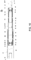
- FIG. 10 omits the first auxiliary structure 28 and the second guiding feature 42 on the first component 48 and the second auxiliary structure 34 and the first guiding feature 40 on the second component 52.
- the first contact feature 32 on the third rail 26 is brought into contact with the upper working portion 114 (or more particularly its first extension section 114a) of the first working member 30, which is now in the second state S2, and can hence drive and thereby retract the second rail 24 with respect to the first rail 22 in the second direction D2, bringing the slide rail assembly back to the retracted state.
- the third rail 26 arrives again at the retracted position R with respect to the first rail 22, both the first working member 30 and the second working member 36 are in the second state S2.
- the lower working portion 116 (or more particularly its second extension section 116b) of the first working member 30 corresponds to the second guiding section 42b of the second guiding feature 42; and when the second working member 36 is in the second state S2 with respect to the second rail 24, the lower working portion 104 (or more particularly its second extension section 104b) of the second working member 36 corresponds to the second auxiliary section 34a of the second auxiliary structure 34.
- the third rail 26 in this state can be displaced with respect to the first rail 22 from the retracted position R in the second direction D2.
- the first contact feature 32 on the third rail 26 is brought into contact with the upper working portion 114 (or more particularly its first extension section 114a) of the first working member 30, which is now in the second state S2, and can therefore help drive the second rail 24 into displacement in the second direction D2; in other words, the second rail 24 and the third rail 26 will be able to be displaced simultaneously in the second direction D2.
- the lower working portion 104 (or more particularly its second extension section 104b) of the second working member 36 in the second state S2 is brought into contact with the second auxiliary section 34a of the second auxiliary structure 34, and the second working member 36 is thus switched from the second state S2 (see FIG. 12 ) to the first state S1 (see FIG. 13 ).
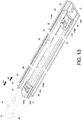
- the lower working portion 116 (or more particularly its second extension section 116b) of the first working member 30 in the second state S2 is brought into contact with the second guiding feature 42 (or more particularly its second guiding section 42b), and the first working member 30 is thus switched from the second state S2 (see FIG. 12 ) to the first state S1 (see FIG. 13 ), allowing the first contact feature 32 to move past the first working member 30 (or more particularly its first extension section 114a), which is now in the first state S1, in the second direction D2, as shown in FIG. 13 .
- the slide rail assembly is in an extended state (such as but not limited to a fully extended state).
- the rear section 60b and the front section 60a of the first slide facilitating device 60 are located between and abut respectively against the fifth blocking feature 80 and the sixth blocking feature 82; for example, the rear section 60b of the first slide facilitating device 60 abuts against the fifth blocking feature 80 of the first rail 22 while the sixth blocking feature 82 of the second rail 24 abuts against the front section 60a of the first slide facilitating device 60.
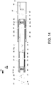
- FIG. 14 omits the first auxiliary structure 28 and the second guiding feature 42 on the first component 48 and the second auxiliary structure 34 and the first guiding feature 40 on the second component 52.
- the second contact feature 38 on the third rail 26 is brought into contact with the lower working portion 104 (or more particularly its first extension section 104a) of the second working member 36, which is now in the first state S1, and can hence drive and thereby retract the second rail 24 with respect to the first rail 22 in the first direction D1, bringing the slide rail assembly to the retracted state again (see FIG. 6 ).
- the working principle involved is similar to that shown in FIG. 11 and FIG. 12 .
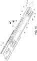
- FIG. 15 and FIG. 16 show a case in which the third rail 26 is being displaced with respect to the first rail 22 in the first direction D1 toward the first extended position P1, and yet in which an unexpected force application (due to some man-made or external factor) has switched the first working member 30 from the second state S2 (e.g., a predetermined state) to the first state S1 (e.g., an unexpected state) such that when the third rail 26 is subsequently displaced from the first extended position P1 in the second direction D2, the first contact feature 32 on the third rail 26 is unable to contact the first working member 30.
- the second state S2 e.g., a predetermined state
- the first state S1 e.g., an unexpected state
- a user can bring the second actuating feature 90 (or more particularly its first actuating section A1 or second actuating section A2) into contact with the lower working portion 116 (or more particularly its first extension section 116a) of the first working member 30, which is now in the first state S1, in order for the second actuating feature 90 to switch the first working member 30 from the first state S1 (see FIG. 15 ) to the second state S2 (see FIG.
- the first contact feature 32 on the third rail 26 will contact the upper working portion 114 (or more particularly its first extension section 114a) of the first working member 30 in the second state S2 so as to drive and thereby retract the second rail 24 with respect to the first rail 22 in the second direction D2.
- a user can operate, i.e., displace, the third rail 26 so that the first actuating feature 88 (or more particularly its first actuating section A1 or second actuating section A2) switches the second working member 36 from the second state S2 to the first state S1, ensuring that while the third rail 26 is being displaced from the second extended position P2 in the first direction D1, the second contact feature 38 on the third rail 26 will contact the second working member 36 in the first state S1 so as to drive and thereby retract the second rail 24 with respect to the first rail 22 in the first direction D1.
- the first actuating feature 88 or more particularly its first actuating section A1 or second actuating section A2
- switches the second working member 36 from the second state S2 to the first state S1 ensuring that while the third rail 26 is being displaced from the second extended position P2 in the first direction D1, the second contact feature 38 on the third rail 26 will contact the second working member 36 in the first state S1 so as to drive and thereby retract the second rail 24 with respect to the first
Landscapes
- Engineering & Computer Science (AREA)
- Computer Hardware Design (AREA)
- General Engineering & Computer Science (AREA)
- Microelectronics & Electronic Packaging (AREA)
- Drawers Of Furniture (AREA)
- Seats For Vehicles (AREA)
Abstract
Description
- The present invention relates to a slide rail assembly and more particularly to one that allows opening in two directions, or a two-way slide rail assembly.
-
FIG. 1 to FIG. 4 ofUS Patent No. 5,871,265 disclose a conventional two-way slide assembly that includes an outer slide member, an inner slide member, and an intermediate slide member mounted between the outer slide member and the inner slide member. As shown inFIG. 4 of the US patent, the arm at one end of the intermediate slide member is provided with two end stops, and the intermediate slide member is prevented from traveling in a certain direction when one of the two end stops contacts the inner slide member. With relatively wide cross sections, however, the slide members take up a considerable amount of space when mounted between a drawer and a cabinet body and may therefore have a negative effect on the storage capacity of the drawer. - As a solution to the problem stated above, the embodiment shown in
FIG. 5 to FIG. 12 of the afore-cited US patent discloses a sequencing latch for preventing the intermediate slide member of a drawer slide assembly from protruding from either end of a two-way cabinet (or rack). When the inner slide member of the drawer slide assembly is moved, the cams on the inner slide member apply a force to a latching arm on the intermediate slide member until the latching arm pivots through an aperture in the intermediate slide member and engages with a receptacle of the outer slide member. While the use of the cams and the receptacle allows for bi-directional travel limitation of the intermediate slide member, the latching mechanism of the sequencing latch shortens the distance for which the intermediate slide member can be displaced, making it relatively inconvenient for a user to access the objects in the drawer. - The present invention relates to a slide rail assembly that allows opening in two directions and whose design has no negative effect on the distance for which each movable rail of the assembly can be displaced.
- The objective of the invention is achieved by the subject-matter of the independent claims. Advantageous embodiments are disclosed by the dependent claims.
- According to one aspect of the present invention, a slide rail assembly includes a first rail, a second rail, a third rail, a first auxiliary structure, a first working member, and a first contact feature. The second rail can be displaced with respect to the first rail, and the third rail with respect to the second rail. The first auxiliary structure is disposed on the first rail. The first working member is movably mounted on the second rail and is configured to be in either one of a first state and a second state with respect to the second rail. The first contact feature is disposed on the third rail. When the third rail is at a retracted position with respect to the first rail, the second rail is retracted with respect to the first rail, and the first working member is in the first state. In the course in which the third rail is displaced from the retracted position to a first extended position in a first direction, the first working member in the first state is brought into contact with the first auxiliary structure and is thus switched from the first state to the second state. In the course in which the third rail is displaced from the first extended position to the retracted position in a second direction, which is the opposite direction of the first direction, the first contact feature on the third rail is brought into contact with the first working member in the second state so as to drive and thereby retract the second rail with respect to the first rail in the second direction.
- Preferably, the slide rail assembly further includes a second working member movably mounted on the second rail and a second contact feature disposed on the third rail. The second working member is configured to be in either one of the first state and the second state with respect to the second rail and is in the first state when the third rail is at the retracted position with respect to the first rail. In the course in which the third rail is displaced from the retracted position to the first extended position in the first direction, the second contact feature on the third rail is brought into contact with the second working member in the first state to displace the second rail in the first direction.
- Preferably, the slide rail assembly further includes a first guiding feature disposed on the first rail. In the course in which the second rail is displaced in the first direction, the second working member in the first state is brought into contact with the first guiding feature and is thus switched from the first state to the second state so that the second contact feature can move past the second working member in the second state in the first direction.
- Preferably, the first working member and the second working member are pivotally connected to the second rail.
- Preferably, the first working member is disposed adjacent to a front portion of the second rail, and the second working member is disposed adjacent to a rear portion of the second rail.
- Preferably, the first contact feature is disposed adjacent to a front portion of the third rail, and the second contact feature is disposed adjacent to a rear portion of the third rail.
- Preferably, the third rail includes an upper wall, a lower wall, and a longitudinal wall connected between the upper wall and the lower wall of the third rail, and the first contact feature and the second contact feature are adjacent to the upper wall and the lower wall of the third rail respectively.
- Preferably, the first auxiliary structure is disposed adjacent to a front portion of the first rail, and the first guiding feature is disposed adjacent to a rear portion of the first rail.
- Preferably, the first rail includes an upper wall, a lower wall, and a longitudinal wall connected between the upper wall and the lower wall of the first rail, and both the first auxiliary structure and the first guiding feature are adjacent to the upper wall of the first rail.
- Preferably, the slide rail assembly further includes a second auxiliary structure and a second guiding feature. In the course in which the third rail is displaced from the retracted position to a second extended position in the second direction, the second working member in the second state is brought into contact with the second auxiliary structure and is thus switched from the second state to the first state. In the course in which the third rail is displaced from the second extended position to the retracted position in the first direction, the second contact feature on the third rail is brought into contact with the second working member in the first state so as to drive and thereby retract the second rail with respect to the first rail in the first direction.
- Preferably, in the course in which the third rail is displaced from the retracted position to the second extended position in the second direction, the first contact feature on the third rail is brought into contact with the first working member in the second state to displace the second rail in the second direction.
- Preferably, in the course in which the second rail is displaced in the second direction, the first working member in the second state is brought into contact with the second guiding feature and is thus switched from the second state to the first state so that the first contact feature can move past the first working member in the first state in the second direction.
- Preferably, the second auxiliary structure is disposed adjacent to the rear portion of the first rail, and the second guiding feature is disposed adjacent to the front portion of the first rail.
- Preferably, both the second auxiliary structure and the second guiding feature are adjacent to the lower wall of the first rail.
- Preferably, the slide rail assembly further includes a first slide facilitating device movably mounted between the first rail and the second rail and a second slide facilitating device movably mounted between the second rail and the third rail.
- Preferably, the first rail is provided with a first blocking feature, and the second rail is provided with a second blocking feature so that when the second rail is at a first predetermined position, a front section and a rear section of the first slide facilitating device are located between and abut respectively against the first blocking feature and the second blocking feature. Preferably, the second rail is provided with a third blocking feature, and the third rail is provided with a fourth blocking feature so that when the third rail is at the first extended position, a front section and a rear section of the second slide facilitating device are located between and abut respectively against the third blocking feature and the fourth blocking feature.
- Preferably, the first rail is provided with a fifth blocking feature, and the second rail is provided with a sixth blocking feature so that when the second rail is at a second predetermined position, the rear section and the front section of the first slide facilitating device are located between and abut respectively against the fifth blocking feature and the sixth blocking feature. Preferably, the second rail is provided with a seventh blocking feature, and the third rail is provided with an eighth blocking feature so that when the third rail is at the second extended position, the rear section and the front section of the second slide facilitating device are located between and abut respectively against the seventh blocking feature and the eighth blocking feature.
- According to another aspect of the present invention, a slide rail assembly includes a first rail, a second rail, a third rail, a working member, and a contact feature. The second rail can be displaced with respect to the first rail, and the third rail with respect to the second rail. The working member is movably mounted on the second rail and can be switched between two states with respect to the second rail. The contact feature is disposed on the third rail. The third rail can be displaced from a retracted position to a first extended position in a first direction, and in the course in which the third rail is displaced from the first extended position to the retracted position in a second direction, which is the opposite direction of the first direction, the contact feature on the third rail is brought into contact with the working member in one of the two states so as to drive and thereby retract the second rail with respect to the first rail in the second direction.
- Preferably, the working member is pivotally connected with respect to the second rail via a shaft whose extending direction is substantially the same as the length direction of the second rail, and an auxiliary structure is disposed on the first rail. In the course in which the third rail is displaced from the retracted position to the first extended position in the first direction, the working member in the other one of the two states is brought into contact with the auxiliary structure and is thus switched from the other one to the one of the two states.
- Preferably, the slide rail assembly further includes a guiding feature disposed on the first rail. In the course in which the third rail is displaced from the retracted position to a second extended position in the second direction, the contact feature on the third rail is brought into contact with the working member in the one of the two states to help displace the second rail in the second direction, and in the course in which the second rail is displaced in the second direction, the working member in the one of the two states is brought into contact with the guiding feature and is thus switched from the one to the other one of the two states so that the contact feature can move past the working member in the other one of the two states in the second direction.
-
-
FIG. 1 is a perspective view of the slide rail assembly according to an embodiment of the present invention; -
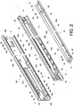
FIG. 2 is an exploded perspective view of the slide rail assembly according to the embodiment of the present invention, showing in particular the first rail, the second rail, and the third rail of the slide rail assembly; -
FIG. 3 is a partial exploded perspective view showing in particular the second rail and a working member of the slide rail assembly according to the embodiment of the present invention; -
FIG. 4 is a schematic view showing that the working member according to the embodiment of the present invention is in a first state with respect to the second rail; -
FIG. 5 is a schematic view showing that the working member according to the embodiment of the present invention is in a second state with respect to the second rail; -
FIG. 6 is a schematic view showing that the slide rail assembly according to the embodiment of the present invention is in a retracted state; -
FIG. 7 is a schematic view showing that the third rail according to the embodiment of the present invention is able to displace the second rail in a first direction; -
FIG. 8 is a schematic view showing that the third rail and the second rail according to the embodiment of the present invention are displaced in the first direction; -
FIG. 9 is a schematic view showing that the third rail and the second rail according to the embodiment of the present invention are further displaced in the first direction; -
FIG. 10 is a schematic view showing that the third rail and the second rail according to the embodiment of the present invention are further displaced in the first direction and thus bring the slide rail assembly into an extended state; -
FIG. 11 is a schematic view showing that the third rail according to the embodiment of the present invention is able to drive and thereby retract the second rail in a second direction with respect to the first rail; -
FIG. 12 is a schematic view showing that the slide rail assembly according to the embodiment of the present invention is in the retracted state; -
FIG. 13 is a schematic view showing that the third rail and the second rail according to the embodiment of the present invention can be displaced in the second direction; -
FIG. 14 is a schematic view showing that the third rail and the second rail according to the embodiment of the present invention are displaced in the second direction and thus bring the slide rail assembly into an extended state; -
FIG. 15 is a schematic view showing that the working member of the second rail is in an unexpected state, and that the contact feature on the third rail is adjacent to the working member; and -
FIG. 16 is a schematic view showing that the working member of the second rail is driven into a predetermined state by the contact feature on the third rail. - Referring to
FIG. 1 andFIG. 2 , the slide rail assembly according to an embodiment of the present invention includes afirst rail 22, asecond rail 24, athird rail 26, a firstauxiliary structure 28, a first workingmember 30, and afirst contact feature 32. Preferably, the slide rail assembly further includes a secondauxiliary structure 34, a second workingmember 36, asecond contact feature 38, afirst guiding feature 40, and asecond guiding feature 42. - The
first rail 22 has a front portion f1 and a rear portion r1. Thefirst rail 22 includes anupper wall 44a, alower wall 44b, and alongitudinal wall 46 connected between theupper wall 44a and thelower wall 44b of thefirst rail 22. Theupper wall 44a, thelower wall 44b, and thelongitudinal wall 46 of thefirst rail 22 jointly define a first channel. - Preferably, the first
auxiliary structure 28 and thesecond guiding feature 42 are provided on thefirst rail 22, e.g., adjacent to the front portion f1 of thefirst rail 22. Here, by way of example, the firstauxiliary structure 28 and thesecond guiding feature 42 are integrated into afirst component 48, and thefirst component 48 is connected to thefirst rail 22 at a position adjacent to the front portion f1. In an alternative embodiment, the firstauxiliary structure 28 and thesecond guiding feature 42 are two independent portions directly integrated into thefirst rail 22. The present invention has no limitation on how the firstauxiliary structure 28 and thesecond guiding feature 42 are provided on thefirst rail 22. Both the firstauxiliary structure 28 and thesecond guiding feature 42 are located in the first channel and protrude transversely with respect to thelongitudinal wall 46 of thefirst rail 22. The firstauxiliary structure 28 includes a firstauxiliary section 28a and afirst wall 28b, which are located at a rear portion and a front portion of the firstauxiliary structure 28 respectively. The firstauxiliary section 28a is an inclined surface or a curved surface. Thesecond guiding feature 42 includes afirst guiding section 42a, asecond guiding section 42b, and amiddle section 42c connected between thefirst guiding section 42a and thesecond guiding section 42b. Themiddle section 42c has a transverse height with respect to thelongitudinal wall 46 of thefirst rail 22, and each of thefirst guiding section 42a and thesecond guiding section 42b is an inclined surface or a curved surface. - Similarly, the second
auxiliary structure 34 and thefirst guiding feature 40 are provided on thefirst rail 22, e.g., adjacent to the rear portion r1 of thefirst rail 22. Here, by way of example, the secondauxiliary structure 34 and thefirst guiding feature 40 are integrated into asecond component 52, and thesecond component 52 is connected to thefirst rail 22 at a position adjacent to the rear portion r1. In an alternative embodiment, the secondauxiliary structure 34 and thefirst guiding feature 40 are two independent portions directly integrated into thefirst rail 22. The present invention has no limitation on how the secondauxiliary structure 34 and thefirst guiding feature 40 are provided on thefirst rail 22. Both the secondauxiliary structure 34 and thefirst guiding feature 40 are located in the first channel and protrude transversely with respect to thelongitudinal wall 46 of thefirst rail 22. The secondauxiliary structure 34 includes a secondauxiliary section 34a and asecond wall 34b, which are located at a front portion and a rear portion of the secondauxiliary structure 34 respectively. The secondauxiliary section 34a is an inclined surface or a curved surface. Thefirst guiding feature 40 includes afirst guiding section 40a, asecond guiding section 40b, and amiddle section 40c connected between thefirst guiding section 40a and thesecond guiding section 40b. Themiddle section 40c has a transverse height with respect to thelongitudinal wall 46 of thefirst rail 22, and each of thefirst guiding section 40a and thesecond guiding section 40b is an inclined surface or a curved surface. - Preferably, both the first
auxiliary structure 28 and thefirst guiding feature 40 are adjacent to theupper wall 44a of thefirst rail 22, and both the secondauxiliary structure 34 and thesecond guiding feature 42 are adjacent to thelower wall 44b of thefirst rail 22. - The
second rail 24 can be displaced with respect to thefirst rail 22. Here, thesecond rail 24 is movably mounted in the first channel of thefirst rail 22 by way of example. Thesecond rail 24 has a front portion f2 and a rear portion r2. Thesecond rail 24 includes anupper wall 56a, alower wall 56b, and alongitudinal wall 58 connected between theupper wall 56a and thesecond wall 56b of thesecond rail 24. Theupper wall 56a, thelower wall 56b, and thelongitudinal wall 58 of thesecond rail 24 jointly define a second channel. - Preferably, both the first working
member 30 and the second workingmember 36 are movably mounted on thesecond rail 24. Here, by way of example, the first workingmember 30 and the second workingmember 36 have substantially the same structural configuration, and both the first workingmember 30 and the second workingmember 36 are pivotally connected to thesecond rail 24. The first workingmember 30 is provided adjacent to the front portion f2 of thesecond rail 24, and the second workingmember 36 is provided adjacent to the rear portion r2 of thesecond rail 24. - Preferably, the slide rail assembly further includes a first
slide facilitating device 60 movably mounted between thefirst rail 22 and thesecond rail 24 so that thefirst rail 22 and thesecond rail 24 can be displaced with respect to each other smoothly. For example, the firstslide facilitating device 60 has anupper portion 61a, alower portion 61b, and amain body portion 63 connected between theupper portion 61a and thelower portion 61b of the firstslide facilitating device 60. Theupper portion 61a is provided with a plurality of first upper rolling members B1 (e.g., rolling balls or rolling wheels) supported between theupper wall 44a of thefirst rail 22 and theupper wall 56a of thesecond rail 24 in a rollable manner, and thelower portion 61b is provided with a plurality of first lower rolling members B2 (e.g., rolling balls or rolling wheels) supported between thelower wall 44b of thefirst rail 22 and thelower wall 56b of thesecond rail 24 in a rollable manner. - Preferably, a
first blocking feature 62 is provided on, and adjacent to the front portion f1 of, thefirst rail 22. Here, thefirst blocking feature 62 protrudes transversely with respect to thelongitudinal wall 46 of thefirst rail 22 by way of example. It is also preferable that thesecond rail 24 is provided with at least onesecond blocking feature 64. Here, by way of example, two second blocking features 64 are located respectively on theupper wall 56a and thelower wall 56b of thesecond rail 24 and are adjacent to the rear portion r2 of thesecond rail 24. - The
third rail 26 can be displaced with respect to thesecond rail 24. Here, thethird rail 26 is movably mounted in the second channel of thesecond rail 24 by way of example. Thethird rail 26 has a front portion f3 and a rear portion r3. Thethird rail 26 includes anupper wall 66a, alower wall 66b, and alongitudinal wall 68 connected between theupper wall 66a and thelower wall 66b of thethird rail 26. - Preferably, both the
first contact feature 32 and thesecond contact feature 38 are provided on thethird rail 26. For example, thefirst contact feature 32 is provided adjacent to the front portion f3 of thethird rail 26, and thesecond contact feature 38 is provided adjacent to the rear portion r3 of thethird rail 26, with thefirst contact feature 32 being adjacent to theupper wall 66a of thethird rail 26, and thesecond contact feature 38 being adjacent to thelower wall 66b of thethird rail 26. - Preferably, the
first contact feature 32 and thesecond contact feature 38 are provided on thelongitudinal wall 68 of thethird rail 26, and thefirst contact feature 32 and thesecond contact feature 38 protrude transversely with respect to thelongitudinal wall 68 of thethird rail 26 toward thelongitudinal wall 58 of thesecond rail 24. - Preferably, the slide rail assembly further includes a second
slide facilitating device 70 movably mounted between thesecond rail 24 and thethird rail 26 so that thesecond rail 24 and thethird rail 26 can be displaced with respect to each other smoothly. For example, the secondslide facilitating device 70 has anupper portion 72a, alower portion 72b, and amain body portion 74 connected between theupper portion 72a and thelower portion 72b of the secondslide facilitating device 70. Theupper portion 72a is provided with a plurality of second upper rolling members B3 (e.g., rolling balls or rolling wheels) supported between theupper wall 56a of thesecond rail 24 and theupper wall 66a of thethird rail 26 in a rollable manner, and thelower portion 72b is provided with a plurality of second lower rolling members B4 (e.g., rolling balls or rolling wheels) supported between thelower wall 56b of thesecond rail 24 and thelower wall 66b of thethird rail 26 in a rollable manner. - Preferably, a
third blocking feature 76 is provided on, and adjacent to the front portion f2 of, thesecond rail 24. Here, thethird blocking feature 76 protrudes transversely with respect to thelongitudinal wall 58 of thesecond rail 24 by way of example. It is also preferable that thethird rail 26 is provided with at least onefourth blocking feature 78. Here, by way of example, two fourth blocking features 78 are located respectively on theupper wall 66a and thelower wall 66b of thethird rail 26 and are adjacent to the rear portion r3 of thethird rail 26. - Preferably, a
fifth blocking feature 80 is provided on, and adjacent to the rear portion r1 of, thefirst rail 22. Here, thefifth blocking feature 80 protrudes transversely with respect to thelongitudinal wall 46 of thefirst rail 22 by way of example. It is also preferable that thesecond rail 24 is provided with at least onesixth blocking feature 82. Here, by way of example, two sixth blocking features 82 are located respectively on theupper wall 56a and thelower wall 56b of thesecond rail 24 and are adjacent to the front portion f2 of thesecond rail 24. - Preferably, a
seventh blocking feature 84 is provided on, and adjacent to the rear portion r2 of, thesecond rail 24. Here, theseventh blocking feature 84 protrudes transversely with respect to thelongitudinal wall 58 of thesecond rail 24 by way of example. It is also preferable that thethird rail 26 is provided with at least oneeighth blocking feature 86. Here, by way of example, two eighth blocking features 86 are located respectively on theupper wall 66a and thelower wall 66b of thethird rail 26 and are adjacent to the front portion f3 of thethird rail 26. - Preferably, the
third rail 26 is further provided with afirst actuating feature 88 and asecond actuating feature 90, which are adjacent to theupper wall 66a and thelower wall 66b of thethird rail 26 respectively. Thefirst actuating feature 88 and thesecond actuating feature 90 have substantially the same structural configuration and both protrude with respect to thelongitudinal wall 68 of thethird rail 26 toward thelongitudinal wall 58 of thesecond rail 24. Take thefirst actuating feature 88 for example. Thefirst actuating feature 88 has a first actuating section A1 at a front portion and a second actuating section A2 at a rear portion. Each of the first actuating section A1 and the second actuating section A2 is an inclined surface or a curved surface. - The first working
member 30 and the second workingmember 36 have substantially the same structural configuration, and the principle by which the first workingmember 30 is mounted on thesecond rail 24 is substantially the same as that by which the second workingmember 36 is mounted on thesecond rail 24. Take the second workingmember 36 for example. Referring toFIG. 3 , the second workingmember 36 is mounted on a base 92 on thesecond rail 24. More specifically, thebase 92 is connected (e.g., fixedly connected) to thelongitudinal wall 58 of thesecond rail 24 by a connectingmember 94 and can therefore be viewed as a part of thesecond rail 24. Thebase 92 includes an upper supportingportion 96a, a lower supportingportion 96b, and aside portion 98 connected between the upper supportingportion 96a and the lower supportingportion 96b. The second workingmember 36 is pivotally connected with respect to thesecond rail 24 via ashaft 100. For example, theshaft 100 is pivotally connected to thebase 92 and extends in a direction that is substantially the same as the length direction of thesecond rail 24, i.e., both directions are longitudinal directions. The second workingmember 36 includes an upper workingportion 102, alower working portion 104, and amiddle portion 106 connected between the upper workingportion 102 and the lower workingportion 104. - Preferably, the
base 92 has a first space K1, and the second rail 24 (or more particularly its longitudinal wall 58) has a second space K2 corresponding to the first space K1. The first space K1 and the second space K2 bring a first side L1 and a second side L2 of thesecond rail 24 into communication with each other, wherein the first side L1 faces the first rail 22 (or more particularly its longitudinal wall 46) and the second side L2 faces the third rail 26 (or more particularly its longitudinal wall 68). - Preferably, the second working
member 36 is received in the first space K1 of thebase 92, and the upper workingportion 102 of the second workingmember 36 branches into afirst extension section 102a and asecond extension section 102b. - As shown in
FIG. 4 and FIG. 5 , each working member (i.e., the first workingmember 30 or the second working member 36) can be moved and thereby switched between two states with respect to thesecond rail 24. Take the second workingmember 36 for example. The second workingmember 36 can be moved with respect to thesecond rail 24 and end up in one of a first state S1 (seeFIG. 4 ) and a second state S2 (seeFIG. 5 ). For example, theshaft 100 allows the second workingmember 36 to pivot from the first state S1 to the second state S2 in a first pivoting direction R1 and from the second state S2 back to the first state S1 in a second pivoting direction R2, which is the opposite direction of the first pivoting direction R1. - Preferably, the second rail 24 (or more particularly the base 92 connected thereto) has an
upper blocking portion 108 and alower blocking portion 110. Thefirst extension section 102a and thesecond extension section 102b of the upper workingportion 102 of the second workingmember 36 define a first receiving space X1 therebetween for receiving theupper blocking portion 108 of the second rail 24 (or more particularly of the base 92), wherein theupper blocking portion 108 has a smaller size than the first receiving space X1. Similarly, thefirst extension section 104a and thesecond extension section 104b of the lower workingportion 104 of the second workingmember 36 define a second receiving space X2 therebetween for receiving thelower blocking portion 110 of the second rail 24 (or more particularly of the base 92), wherein thelower blocking portion 110 has a smaller size than the second receiving space X2. - Preferably, when the second working
member 36 is in the first state S1 (seeFIG. 4 ), thefirst extension section 102a of the upper workingportion 102 of the second workingmember 36 is blocked in the second pivoting direction R2 by theupper blocking portion 108 of thesecond rail 24 and thus produces a position-limiting effect. Similarly, once the second workingmember 36 is pivoted from the first state S1 to the second state S2 (seeFIG. 5 ), thefirst extension section 104a of the lower workingportion 104 of the second workingmember 36 is blocked in the first pivoting direction R1 by thelower blocking portion 110 of thesecond rail 24 and thus produces a position-limiting effect. - Preferably, referring back to
FIG. 3 , one of the second workingmember 36 and thebase 92 has at least one retaining feature 112 (such as but not limited to a rib) for providing frictional resistance between the second workingmember 36 and the base 92 while the second workingmember 36 is being pivoted with respect to thebase 92, thereby helping to retain the second workingmember 36 in the first state S1 or the second state S2. -
FIG. 6 shows the slide rail assembly in a retracted state. Preferably, the first workingmember 30 corresponds to an intermediate position between the firstauxiliary structure 28 and thesecond guiding feature 42 of thefirst rail 22, and the second workingmember 36 corresponds to an intermediate position between the secondauxiliary structure 34 and thefirst guiding feature 40 of thefirst rail 22. Please note thatFIG. 6 omits the firstslide facilitating device 60, the secondslide facilitating device 70, thelower wall 44b of thefirst rail 22, thelower wall 56b of thesecond rail 24, and thelower wall 66b of thethird rail 26. - More specifically, when the
third rail 26 is at a retracted position R with respect to thefirst rail 22, thesecond rail 24 is retracted with respect to thefirst rail 22, and the first workingmember 30 is in the first state S1. For example, while the first workingmember 30 is in the first state S1 with respect to thesecond rail 24, the upper workingportion 114 of the first workingmember 30 is sunken toward and hence close to the first rail 22 (or more particularly its longitudinal wall 46), with thesecond extension section 114b of the upper workingportion 114 corresponding to the firstauxiliary section 28a of the firstauxiliary structure 28, and thefirst extension section 114a of the upper workingportion 114 being offset from thefirst contact feature 32 on thethird rail 26; on the other hand, the lower workingportion 116 of the first workingmember 30 is tilted up toward and hence close to the third rail 26 (or more particularly its longitudinal wall 68), with thesecond extension section 116b of the lower workingportion 116 being offset from thesecond guiding feature 42 of thefirst rail 22. - Preferably, the second working
member 36 is also in the first state S1 when thethird rail 26 is at the retracted position R with respect to thefirst rail 22. For example, while the second workingmember 36 is in the first state S1 with respect to thesecond rail 24, the upper workingportion 102 of the second workingmember 36 is sunken toward and hence close to the first rail 22 (or more particularly its longitudinal wall 46), with thesecond extension section 102b of the upper workingportion 102 corresponding to thesecond guiding section 40b of thefirst guiding feature 40; on the other hand, the lower workingportion 104 of the second workingmember 36 is tilted up toward and hence close to the third rail 26 (or more particularly its longitudinal wall 68), with thefirst extension section 104a of the lower workingportion 104 corresponding to thesecond contact feature 38 on thethird rail 26. - Referring to
FIG. 6 andFIG. 7 , thethird rail 26 can be displaced from the retracted position R in a first direction D1 or a second direction D2, which is the opposite direction of the first direction D1. Here, by way of example, thethird rail 26 is displaced in the first direction D1 to begin with. In the course in which thethird rail 26 is displaced in the first direction D1 to a first extended position, thesecond contact feature 38 on thethird rail 26 is brought into contact with the lower working portion 104 (or more particularly itsfirst extension section 104a) of the second workingmember 36, which is now in the first state S1, and can therefore help drive thesecond rail 24 into displacement in the first direction D1; in other words, thesecond rail 24 and thethird rail 26 will be able to be displaced simultaneously in the first direction D1. - Referring to
FIG. 7 andFIG. 8 , in the course in which thesecond rail 24 is displaced in the first direction D1 along with thethird rail 26, the upper working portion 102 (or more particularly itssecond extension section 102b) of the second workingmember 36 in the first state S1 (seeFIG. 7 ) is brought into contact with thesecond guiding section 40b of thefirst guiding feature 40, and the second workingmember 36 is switched from the first state S1 (seeFIG. 7 ) to the second state S2 (seeFIG. 8 ) as a result. As shown inFIG. 8 , the upper workingportion 102 of the second workingmember 36 is configured to be guided by thesecond guiding section 40b of thefirst guiding feature 40 and will eventually move past thefirst guiding feature 40 such that the lower working portion 104 (or more particularly itsfirst extension section 104a) of the second workingmember 36 no longer corresponds to, but is offset from, thesecond contact feature 38 on thethird rail 26, thereby allowing thesecond contact feature 38 on thethird rail 26 to move past the second working member 36 (which is now in the second state S2) in the first direction D1; that is to say, thesecond rail 24 and thethird rail 26 will no longer be able to be simultaneously displaced in the first direction D1. - Referring to
FIG. 8 andFIG. 9 , while thethird rail 26 is being further displaced in the first direction D1, thesecond rail 24 is displaced in the first direction D1 differentially with respect to thethird rail 26. During the process, the upper working portion 114 (or more particularly itssecond extension section 114b) of the first workingmember 30 in the first state S1 is brought into contact with the firstauxiliary section 28a of the firstauxiliary structure 28, thereby switching the first workingmember 30 from the first state S1 (seeFIG. 8 ) to the second state S2 (seeFIG. 9 ). As shown inFIG. 9 , the upper workingportion 114 of the first workingmember 30 is configured to be guided by the firstauxiliary section 28a of the firstauxiliary structure 28 and will eventually move past the firstauxiliary structure 28, and once the first workingmember 30 enters the second state S2, the upper workingportion 114 of the first workingmember 30 is no longer offset from thefirst contact feature 32 on thethird rail 26. In other words, the upper working portion 114 (or more particularly itsfirst extension section 114a) of the first workingmember 30 corresponds to thefirst contact feature 32 on thethird rail 26 when the first workingmember 30 is in the second state S2. - Referring to
FIG. 9 andFIG. 10 , when thethird rail 26 reaches the first extended position P1 after being further displaced with respect to thefirst rail 22 in the first direction D1, thesecond rail 24 arrives at a first predetermined position Y1, and the slide rail assembly is in an extended state (such as but not limited to a fully extended state). - Preferably, when the
second rail 24 is at the first predetermined position Y1 with respect to thefirst rail 22, afront section 60a and arear section 60b of the firstslide facilitating device 60 are located between and abut respectively against thefirst blocking feature 62 and thesecond blocking feature 64; for example, thefront section 60a of the firstslide facilitating device 60 abuts against thefirst blocking feature 62 of thefirst rail 22 while thesecond blocking feature 64 of thesecond rail 24 abuts against therear section 60b of the firstslide facilitating device 60. It is also preferable that when thethird rail 26 is at the first extended position P1, afront section 70a and arear section 70b of the secondslide facilitating device 70 are located between and abut respectively against thethird blocking feature 76 and thefourth blocking feature 78; for example, thefront section 70a of the secondslide facilitating device 70 abuts against thethird blocking feature 76 of thesecond rail 24 while thefourth blocking feature 78 of thethird rail 26 abuts against therear section 70b of the secondslide facilitating device 70. It is worth mentioning thatFIG. 10 omits the firstauxiliary structure 28 and thesecond guiding feature 42 on thefirst component 48 and the secondauxiliary structure 34 and thefirst guiding feature 40 on thesecond component 52. - Referring to
FIG. 11 andFIG. 12 , in the course in which thethird rail 26 is displaced from the first extended position PI to the retracted position R in the second direction D2, thefirst contact feature 32 on thethird rail 26 is brought into contact with the upper working portion 114 (or more particularly itsfirst extension section 114a) of the first workingmember 30, which is now in the second state S2, and can hence drive and thereby retract thesecond rail 24 with respect to thefirst rail 22 in the second direction D2, bringing the slide rail assembly back to the retracted state. It is worth mentioning that when thethird rail 26 arrives again at the retracted position R with respect to thefirst rail 22, both the first workingmember 30 and the second workingmember 36 are in the second state S2. - Referring to
FIG. 12 , when the first workingmember 30 is in the second state S2 with respect to thesecond rail 24, the lower working portion 116 (or more particularly itssecond extension section 116b) of the first workingmember 30 corresponds to thesecond guiding section 42b of thesecond guiding feature 42; and when the second workingmember 36 is in the second state S2 with respect to thesecond rail 24, the lower working portion 104 (or more particularly itssecond extension section 104b) of the second workingmember 36 corresponds to the secondauxiliary section 34a of the secondauxiliary structure 34. Thethird rail 26 in this state can be displaced with respect to thefirst rail 22 from the retracted position R in the second direction D2. While thethird rail 26 is being displaced to a second extended position in the second direction D2, thefirst contact feature 32 on thethird rail 26 is brought into contact with the upper working portion 114 (or more particularly itsfirst extension section 114a) of the first workingmember 30, which is now in the second state S2, and can therefore help drive thesecond rail 24 into displacement in the second direction D2; in other words, thesecond rail 24 and thethird rail 26 will be able to be displaced simultaneously in the second direction D2. - Referring to
FIG. 12 andFIG. 13 , in the course in which thethird rail 26 is displaced from the retracted position R in the second direction D2, the lower working portion 104 (or more particularly itssecond extension section 104b) of the second workingmember 36 in the second state S2 is brought into contact with the secondauxiliary section 34a of the secondauxiliary structure 34, and the second workingmember 36 is thus switched from the second state S2 (seeFIG. 12 ) to the first state S1 (seeFIG. 13 ). Moreover, in the course in which thesecond rail 24 is displaced in the second direction D2, the lower working portion 116 (or more particularly itssecond extension section 116b) of the first workingmember 30 in the second state S2 is brought into contact with the second guiding feature 42 (or more particularly itssecond guiding section 42b), and the first workingmember 30 is thus switched from the second state S2 (seeFIG. 12 ) to the first state S1 (seeFIG. 13 ), allowing thefirst contact feature 32 to move past the first working member 30 (or more particularly itsfirst extension section 114a), which is now in the first state S1, in the second direction D2, as shown inFIG. 13 . - Referring to
FIG. 14 , when thethird rail 26 reaches the second extended position P2 after being further displaced with respect to thefirst rail 22 in the second direction D2, thesecond rail 24 arrives at a second predetermined position Y2, and the slide rail assembly is in an extended state (such as but not limited to a fully extended state). - Preferably, when the
second rail 24 is at the second predetermined position Y2 with respect to thefirst rail 22, therear section 60b and thefront section 60a of the firstslide facilitating device 60 are located between and abut respectively against thefifth blocking feature 80 and thesixth blocking feature 82; for example, therear section 60b of the firstslide facilitating device 60 abuts against thefifth blocking feature 80 of thefirst rail 22 while thesixth blocking feature 82 of thesecond rail 24 abuts against thefront section 60a of the firstslide facilitating device 60. It is also preferable that when thethird rail 26 is at the second extended position P2, therear section 70b and thefront section 70a of the secondslide facilitating device 70 are located between and abut respectively against theseventh blocking feature 84 and theeighth blocking feature 86; for example, therear section 70b of the secondslide facilitating device 70 abuts against theseventh blocking feature 84 of thesecond rail 24 while theeighth blocking feature 86 of thethird rail 26 abuts against thefront section 70a of the secondslide facilitating device 70. It is worth mentioning thatFIG. 14 omits the firstauxiliary structure 28 and thesecond guiding feature 42 on thefirst component 48 and the secondauxiliary structure 34 and thefirst guiding feature 40 on thesecond component 52. - Referring sequentially to
FIG. 14 andFIG. 13 , in the course in which thethird rail 26 is displaced from the second extended position P2 to the retracted position R in the first direction D1, thesecond contact feature 38 on thethird rail 26 is brought into contact with the lower working portion 104 (or more particularly itsfirst extension section 104a) of the second workingmember 36, which is now in the first state S1, and can hence drive and thereby retract thesecond rail 24 with respect to thefirst rail 22 in the first direction D1, bringing the slide rail assembly to the retracted state again (seeFIG. 6 ). The working principle involved is similar to that shown inFIG. 11 andFIG. 12 . -
FIG. 15 andFIG. 16 show a case in which thethird rail 26 is being displaced with respect to thefirst rail 22 in the first direction D1 toward the first extended position P1, and yet in which an unexpected force application (due to some man-made or external factor) has switched the first workingmember 30 from the second state S2 (e.g., a predetermined state) to the first state S1 (e.g., an unexpected state) such that when thethird rail 26 is subsequently displaced from the first extended position P1 in the second direction D2, thefirst contact feature 32 on thethird rail 26 is unable to contact the first workingmember 30. By operating, i.e., displacing, thethird rail 26, however, a user can bring the second actuating feature 90 (or more particularly its first actuating section A1 or second actuating section A2) into contact with the lower working portion 116 (or more particularly itsfirst extension section 116a) of the first workingmember 30, which is now in the first state S1, in order for thesecond actuating feature 90 to switch the first workingmember 30 from the first state S1 (seeFIG. 15 ) to the second state S2 (seeFIG. 16 ), ensuring that while thethird rail 26 is being displaced from the first extended position P1 in the second direction D2, thefirst contact feature 32 on thethird rail 26 will contact the upper working portion 114 (or more particularly itsfirst extension section 114a) of the first workingmember 30 in the second state S2 so as to drive and thereby retract thesecond rail 24 with respect to thefirst rail 22 in the second direction D2. - By the same working principle, a user can operate, i.e., displace, the
third rail 26 so that the first actuating feature 88 (or more particularly its first actuating section A1 or second actuating section A2) switches the second workingmember 36 from the second state S2 to the first state S1, ensuring that while thethird rail 26 is being displaced from the second extended position P2 in the first direction D1, thesecond contact feature 38 on thethird rail 26 will contact the second workingmember 36 in the first state S1 so as to drive and thereby retract thesecond rail 24 with respect to thefirst rail 22 in the first direction D1. - It can be known from the above that the embodiment described above preferably has the following features:
- 1. While the
third rail 26 is being retracted with respect to thefirst rail 22 from an extended position (e.g., the first extended position P1 or the second extended position P2), one of the contact features will contact the corresponding working member in the predetermined state to ensure that thesecond rail 24 can be retracted with respect to thefirst rail 22. - 2. The
third rail 26 as well as thesecond rail 24 can be pulled out with respect to thefirst rail 22 in two opposite directions (e.g., the first direction D1 and the second direction D2) to enable two-way opening without producing any negative effect on the distance for which each of thesecond rail 24 and thethird rail 26 can be displaced. - While the present invention has been disclosed through the foregoing embodiment, it should be understood that the embodiment is not intended to be restrictive of the scope of the invention. The scope of the patent protection sought by the applicant is defined by the appended claims.
Claims (15)
- A slide rail assembly, comprising:a first rail (22);a second rail (24) displaceable with respect to the first rail (22); anda third rail (26) displaceable with respect to the second rail (24);characterized inthat the slide rail assembly further comprises:a first auxiliary structure (28) disposed on the first rail (22);a first working member (30) movably mounted on the second rail (24) and configured to be in either one of a first state (S1) and a second state (S2) with respect to the second rail (24); anda first contact feature (32) disposed on the third rail (26);wherein when the third rail (26) is at a retracted position (R) with respect to the first rail (22), the second rail (24) is retracted with respect to the first rail (22), and the first working member (30) is in the first state (S1);wherein while the third rail (26) is being displaced from the retracted position (R) to a first extended position (P1) in a first direction (D1), the first working member (30) in the first state (S1) is brought into contact with the first auxiliary structure (28) and is thus switched from the first state (S1) to the second state (S2);wherein while the third rail (26) is being displaced from the first extended position (P1) to the retracted position (R) in a second direction (D2), which is the opposite direction of the first direction (D1), the first contact feature (32) on the third rail (26) is brought into contact with the first working member (30) in the second state (S2) so as to drive and thereby retract the second rail (24) with respect to the first rail (22) in the second direction (D2).
- The slide rail assembly as claimed in claim 1, further comprising a second working member (36) movably mounted on the second rail (24) and a second contact feature (38) disposed on the third rail (26), wherein the second working member (36) is configured to be in either one of the first state (S1) and the second state (S2) with respect to the second rail (24); the second working member (36) is in the first state (S1) when the third rail (26) is at the retracted position (R) with respect to the first rail (22); and while the third rail (26) is being displaced from the retracted position (R) to the first extended position (P1) in the first direction (D1), the second contact feature (38) on the third rail (26) is brought into contact with the second working member (36) in the first state (S1) to help displace the second rail (24) in the first direction (D1).
- The slide rail assembly as claimed in claim 2, wherein the first working member (30) and the second working member (36) are pivotally connected to the second rail (24); wherein the first working member (30) is disposed adjacent to a front portion (f2) of the second rail (24), and the second working member (36) is disposed adjacent to a rear portion (r2) of the second rail (24).
- The slide rail assembly as claimed in claim 2 or 3, wherein the first contact feature (32) is disposed adjacent to a front portion (f3) of the third rail (26), and the second contact feature (38) is disposed adjacent to a rear portion (r3) of the third rail (26); wherein the third rail (26) includes an upper wall (66a), a lower wall (66b), and a longitudinal wall (68) connected between the upper wall (66a) and the lower wall (66b) of the third rail (26), and the first contact feature (32) and the second contact feature (38) are adjacent to the upper wall (66a) and the lower wall (66b) of the third rail (26) respectively.
- The slide rail assembly as claimed in any of claims 2-4, further comprising a first guiding feature (40) disposed on the first rail (22), wherein while the second rail (24) is being displaced in the first direction (D1), the second working member (36) in the first state (S1) is brought into contact with the first guiding feature (40) and is thus switched from the first state (S1) to the second state (S2), allowing the second contact feature (38) to move past the second working member (36) in the second state (S2) in the first direction (D1).
- The slide rail assembly as claimed in claim 5, wherein the first auxiliary structure (28) is disposed adjacent to a front portion (f1) of the first rail (22), and the first guiding feature (40) is disposed adjacent to a rear portion (r1) of the first rail (22); wherein the first rail (22) includes an upper wall (44a), a lower wall (44b), and a longitudinal wall (46) connected between the upper wall (44a) and the lower wall (44b) of the first rail (22), and both the first auxiliary structure (28) and the first guiding feature (40) are adjacent to the upper wall (44a) of the first rail (22).
- The slide rail assembly as claimed in claim 5 or 6, further comprising a second auxiliary structure (34) and a second guiding feature (42), wherein while the third rail (26) is being displaced from the retracted position (R) to a second extended position (P2) in the second direction (D2), the second working member (36) in the second state (S2) is brought into contact with the second auxiliary structure (34) and is thus switched from the second state (S2) to the first state (S1); and while the third rail (26) is being displaced from the second extended position (P2) to the retracted position (R) in the first direction (D1), the second contact feature (38) on the third rail (26) is brought into contact with the second working member (36) in the first state (S1) so as to drive and thereby retract the second rail (24) with respect to the first rail (22) in the first direction (D1).
- The slide rail assembly as claimed in claim 7, wherein while the third rail (26) is being displaced from the retracted position (R) to the second extended position (P2) in the second direction (D2), the first contact feature (32) on the third rail (26) is brought into contact with the first working member (30) in the second state (S2) to displace the second rail (24) in the second direction (D2).
- The slide rail assembly as claimed in claim 7 or 8, wherein while the second rail (24) is being displaced in the second direction (D2), the first working member (30) in the second state (S2) is brought into contact with the second guiding feature (42) and is thus switched from the second state (S2) to the first state (S1), allowing the first contact feature (32) to move past the first working member (30) in the first state (S1) in the second direction (D2).
- The slide rail assembly as claimed in any of claims 7-9, wherein the second auxiliary structure (34) is disposed adjacent to the rear portion (r1) of the first rail (22), and the second guiding feature (42) is disposed adjacent to the front portion (f1) of the first rail (22); wherein both the second auxiliary structure (34) and the second guiding feature (42) are adjacent to the lower wall (44b) of the first rail (22).
- The slide rail assembly as claimed in any of claims 2-10, further comprising a first slide facilitating device (60) movably mounted between the first rail (22) and the second rail (24) and a second slide facilitating device (70) movably mounted between the second rail (24) and the third rail (26).
- The slide rail assembly as claimed in claim 11, wherein the first rail (22) is provided with a first blocking feature (62), the second rail (24) is provided with a second blocking feature (64), and when the second rail (24) is at a first predetermined position (Y1), a front section (60a) and a rear section (60b) of the first slide facilitating device (60) are located between and abut respectively against the first blocking feature (62) and the second blocking feature (64); wherein the second rail (24) is provided with a third blocking feature (76), the third rail (26) is provided with a fourth blocking feature (78), and when the third rail (26) is at the first extended position (P1), a front section (70a) and a rear section (70b) of the second slide facilitating device (70) are located between and abut respectively against the third blocking feature (76) and the fourth blocking feature (78); wherein the first rail (22) is provided with a fifth blocking feature (80), the second rail (24) is provided with a sixth blocking feature (82), and when the second rail (24) is at a second predetermined position (Y2), the rear section (60b) and the front section (60a) of the first slide facilitating device (60) are located between and abut respectively against the fifth blocking feature (80) and the sixth blocking feature (82); and wherein the second rail (24) is provided with a seventh blocking feature (84), the third rail (26) is provided with an eighth blocking feature (86), and when the third rail (26) is at the second extended position (P2), the rear section (70b) and the front section (70a) of the second slide facilitating device (70) are located between and abut respectively against the seventh blocking feature (84) and the eighth blocking feature (86).
- A slide rail assembly, comprising:a first rail (22);a second rail (24) displaceable with respect to the first rail (22); anda third rail (26) displaceable with respect to the second rail (24);characterized inthat the slide rail assembly further comprise:a working member (30) movably mounted on the second rail (24) and switchable between two states (S1, S2) with respect to the second rail (24);anda contact feature (32) disposed on the third rail (26);wherein the third rail (26) is displaceable from a retracted position (R) to a first extended position (P1) in a first direction (D1);wherein while the third rail (26) is being displaced from the first extended position (P1) to the retracted position (R) in a second direction (D2), which is the opposite direction of the first direction (D1), the contact feature (32) on the third rail (26) is brought into contact with the working member (30) in one of the two states (S1, S2) so as to drive and thereby retract the second rail (24) with respect to the first rail (22) in the second direction (D2).
- The slide rail assembly as claimed in claim 13, wherein the working member (30) is pivotally connected with respect to the second rail (24) via a shaft (100), the shaft (100) extends in a direction substantially identical to a length direction of the second rail (24), an auxiliary structure (28) is disposed on the first rail (22), and while the third rail (26) is being displaced from the retracted position (R) to the first extended position (P1) in the first direction (D1), the working member (30) in the other one of the two states (S1, S2) is brought into contact with the auxiliary structure (28) and is thus switched from the other one to the one of the two states (S1, S2).
- The slide rail assembly as claimed in claim 13 or 14, further comprising a guiding feature (42) disposed on the first rail (22), wherein while the third rail (26) is being displaced from the retracted position (R) to a second extended position (P2) in the second direction (D2), the contact feature (32) on the third rail (26) is brought into contact with the working member (30) in the one of the two states (S1, S2) to displace the second rail (24) in the second direction (D2); and while the second rail (24) is being displaced in the second direction (D2), the working member (30) in the one of the two states (S1, S2) is brought into contact with the guiding feature (42) and is thus switched from the one to the other one of the two states (S1, S2), allowing the contact feature (32) to move past the working member (30) in the other one of the two states (S1, S2) in the second direction (D2).
Applications Claiming Priority (1)
| Application Number | Priority Date | Filing Date | Title |
|---|---|---|---|
| TW109104916A TWI710340B (en) | 2020-02-14 | 2020-02-14 | Slide rail assembly |
Publications (2)
| Publication Number | Publication Date |
|---|---|
| EP3865003A1 true EP3865003A1 (en) | 2021-08-18 |
| EP3865003B1 EP3865003B1 (en) | 2022-10-12 |
Family
ID=71092377
Family Applications (1)
| Application Number | Title | Priority Date | Filing Date |
|---|---|---|---|
| EP20179445.0A Active EP3865003B1 (en) | 2020-02-14 | 2020-06-11 | Slide rail assembly |
Country Status (4)
| Country | Link |
|---|---|
| US (1) | US11140983B2 (en) |
| EP (1) | EP3865003B1 (en) |
| JP (1) | JP7022788B2 (en) |
| TW (1) | TWI710340B (en) |
Families Citing this family (3)
| Publication number | Priority date | Publication date | Assignee | Title |
|---|---|---|---|---|
| DE102022130217A1 (en) * | 2022-11-15 | 2024-05-16 | Accuride International Gmbh | Sliding stop device |
| US20240415368A1 (en) * | 2023-06-15 | 2024-12-19 | Haier Us Appliance Solutions, Inc. | End cap as engagement and disengagement mechanism for a slide assembly |
| CN117356854A (en) * | 2023-10-31 | 2024-01-09 | 清远市星徽精密制造有限公司 | A portable guide rail interlocking mechanism |
Citations (5)
| Publication number | Priority date | Publication date | Assignee | Title |
|---|---|---|---|---|
| US4872734A (en) * | 1987-06-22 | 1989-10-10 | Robert Rechberg | Drawer slides with self-actuating latching systems |
| US5871265A (en) | 1996-10-09 | 1999-02-16 | Accuride International Inc. | Two-way slide |
| US20070164644A1 (en) * | 2006-01-19 | 2007-07-19 | Shih-Long Hwang | Locating structure for a slide assembly |
| US20110135224A1 (en) * | 2009-12-04 | 2011-06-09 | King Slide Works Co., Ltd. | Slide assembly |
| US20140265792A1 (en) * | 2013-03-18 | 2014-09-18 | Nan Juen International Co., Ltd. | Pres-control type sliding rail assembly |
Family Cites Families (7)
| Publication number | Priority date | Publication date | Assignee | Title |
|---|---|---|---|---|
| TW566128U (en) * | 2003-03-03 | 2003-12-11 | Nan Juen Int Co Ltd | Structure of rail capable of synchronous drawing out and pushing in |
| US8132875B2 (en) * | 2008-08-18 | 2012-03-13 | Jheng-Hong Juang | Three-sectional rail structure |
| JP3177386U (en) * | 2012-05-19 | 2012-08-02 | 宜瑪工業股▲ふん▼有限公司 | Slide rail for two-way drawer and its drawer set |
| US8511765B1 (en) | 2012-08-07 | 2013-08-20 | E-Make Co., Ltd. | Two way travel drawer slide |
| US8733864B2 (en) | 2012-08-08 | 2014-05-27 | E-Make Co., Ltd. | Two way drawer slide |
| US9279280B1 (en) * | 2014-08-28 | 2016-03-08 | King Slide Works Co., Ltd. | Slide rail assembly |
| JP6647762B2 (en) * | 2018-01-31 | 2020-02-14 | スガツネ工業株式会社 | Holding device |
-
2020
- 2020-02-14 TW TW109104916A patent/TWI710340B/en active
- 2020-06-04 US US16/892,676 patent/US11140983B2/en active Active
- 2020-06-11 EP EP20179445.0A patent/EP3865003B1/en active Active
- 2020-07-08 JP JP2020117495A patent/JP7022788B2/en active Active
Patent Citations (5)
| Publication number | Priority date | Publication date | Assignee | Title |
|---|---|---|---|---|
| US4872734A (en) * | 1987-06-22 | 1989-10-10 | Robert Rechberg | Drawer slides with self-actuating latching systems |
| US5871265A (en) | 1996-10-09 | 1999-02-16 | Accuride International Inc. | Two-way slide |
| US20070164644A1 (en) * | 2006-01-19 | 2007-07-19 | Shih-Long Hwang | Locating structure for a slide assembly |
| US20110135224A1 (en) * | 2009-12-04 | 2011-06-09 | King Slide Works Co., Ltd. | Slide assembly |
| US20140265792A1 (en) * | 2013-03-18 | 2014-09-18 | Nan Juen International Co., Ltd. | Pres-control type sliding rail assembly |
Also Published As
| Publication number | Publication date |
|---|---|
| US11140983B2 (en) | 2021-10-12 |
| EP3865003B1 (en) | 2022-10-12 |
| US20210251385A1 (en) | 2021-08-19 |
| TW202130304A (en) | 2021-08-16 |
| TWI710340B (en) | 2020-11-21 |
| JP2021126492A (en) | 2021-09-02 |
| JP7022788B2 (en) | 2022-02-18 |
Similar Documents
| Publication | Publication Date | Title |
|---|---|---|
| EP3865003B1 (en) | Slide rail assembly | |
| TWI704889B (en) | Slide rail assembly | |
| EP3763247B1 (en) | Slide rail assembly | |
| EP3750445B1 (en) | Slide rail assembly and operation method thereof | |
| EP3763246B1 (en) | Slide rail assembly | |
| EP4035568A1 (en) | Slide rail assembly | |
| EP3808215B1 (en) | Slide rail assembly | |
| JP6945021B2 (en) | Slide rail assembly and its slide rail kit | |
| EP4327696A1 (en) | Slide rail assembly | |
| EP4537705A1 (en) | Slide rail assembly | |
| EP3225132A1 (en) | Driving mechanism and driving method for furniture parts | |
| TW202112275A (en) | Slide rail assembly | |
| EP3840552A1 (en) | Slide rail assembly | |
| EP4570126A1 (en) | Slide rail assembly | |
| EP3763245B1 (en) | Slide rail assembly | |
| EP4501174B1 (en) | Slide rail assembly | |
| CN114680489B (en) | Slide rail assembly and slide rail external member thereof | |
| EP4327697A1 (en) | Slide rail assembly and slide rail kit | |
| EP4563040A1 (en) | Slide rail assembly | |
| EP3387951B1 (en) | Clutch system for furniture parts | |
| CN114847691B (en) | Sliding rail assembly | |
| CN113273829A (en) | Sliding rail assembly | |
| EP4403732A1 (en) | Slide rail mechanism | |
| CN111425522B (en) | Slide rail assembly and slide rail external member thereof | |
| EP4563039A1 (en) | Slide rail assembly |
Legal Events
| Date | Code | Title | Description |
|---|---|---|---|
| PUAI | Public reference made under article 153(3) epc to a published international application that has entered the european phase |
Free format text: ORIGINAL CODE: 0009012 |
|
| STAA | Information on the status of an ep patent application or granted ep patent |
Free format text: STATUS: REQUEST FOR EXAMINATION WAS MADE |
|
| 17P | Request for examination filed |
Effective date: 20210625 |
|
| AK | Designated contracting states |
Kind code of ref document: A1 Designated state(s): AL AT BE BG CH CY CZ DE DK EE ES FI FR GB GR HR HU IE IS IT LI LT LU LV MC MK MT NL NO PL PT RO RS SE SI SK SM TR |
|
| GRAP | Despatch of communication of intention to grant a patent |
Free format text: ORIGINAL CODE: EPIDOSNIGR1 |
|
| STAA | Information on the status of an ep patent application or granted ep patent |
Free format text: STATUS: GRANT OF PATENT IS INTENDED |
|
| RIC1 | Information provided on ipc code assigned before grant |
Ipc: H05K 7/14 20060101ALN20220331BHEP Ipc: A47B 88/403 20170101ALI20220331BHEP Ipc: A47B 88/423 20170101ALI20220331BHEP Ipc: A47B 88/493 20170101AFI20220331BHEP |
|
| INTG | Intention to grant announced |
Effective date: 20220503 |
|
| GRAS | Grant fee paid |
Free format text: ORIGINAL CODE: EPIDOSNIGR3 |
|
| GRAA | (expected) grant |
Free format text: ORIGINAL CODE: 0009210 |
|
| STAA | Information on the status of an ep patent application or granted ep patent |
Free format text: STATUS: THE PATENT HAS BEEN GRANTED |
|
| AK | Designated contracting states |
Kind code of ref document: B1 Designated state(s): AL AT BE BG CH CY CZ DE DK EE ES FI FR GB GR HR HU IE IS IT LI LT LU LV MC MK MT NL NO PL PT RO RS SE SI SK SM TR |
|
| REG | Reference to a national code |
Ref country code: GB Ref legal event code: FG4D |
|
| REG | Reference to a national code |
Ref country code: CH Ref legal event code: EP |
|
| REG | Reference to a national code |
Ref country code: DE Ref legal event code: R096 Ref document number: 602020005563 Country of ref document: DE |
|
| REG | Reference to a national code |
Ref country code: IE Ref legal event code: FG4D |
|
| REG | Reference to a national code |
Ref country code: AT Ref legal event code: REF Ref document number: 1523628 Country of ref document: AT Kind code of ref document: T Effective date: 20221115 |
|
| REG | Reference to a national code |
Ref country code: LT Ref legal event code: MG9D |
|
| REG | Reference to a national code |
Ref country code: NL Ref legal event code: MP Effective date: 20221012 |
|
| REG | Reference to a national code |
Ref country code: AT Ref legal event code: MK05 Ref document number: 1523628 Country of ref document: AT Kind code of ref document: T Effective date: 20221012 |
|
| PG25 | Lapsed in a contracting state [announced via postgrant information from national office to epo] |
Ref country code: NL Free format text: LAPSE BECAUSE OF FAILURE TO SUBMIT A TRANSLATION OF THE DESCRIPTION OR TO PAY THE FEE WITHIN THE PRESCRIBED TIME-LIMIT Effective date: 20221012 |
|
| PG25 | Lapsed in a contracting state [announced via postgrant information from national office to epo] |
Ref country code: SE Free format text: LAPSE BECAUSE OF FAILURE TO SUBMIT A TRANSLATION OF THE DESCRIPTION OR TO PAY THE FEE WITHIN THE PRESCRIBED TIME-LIMIT Effective date: 20221012 Ref country code: PT Free format text: LAPSE BECAUSE OF FAILURE TO SUBMIT A TRANSLATION OF THE DESCRIPTION OR TO PAY THE FEE WITHIN THE PRESCRIBED TIME-LIMIT Effective date: 20230213 Ref country code: NO Free format text: LAPSE BECAUSE OF FAILURE TO SUBMIT A TRANSLATION OF THE DESCRIPTION OR TO PAY THE FEE WITHIN THE PRESCRIBED TIME-LIMIT Effective date: 20230112 Ref country code: LT Free format text: LAPSE BECAUSE OF FAILURE TO SUBMIT A TRANSLATION OF THE DESCRIPTION OR TO PAY THE FEE WITHIN THE PRESCRIBED TIME-LIMIT Effective date: 20221012 Ref country code: FI Free format text: LAPSE BECAUSE OF FAILURE TO SUBMIT A TRANSLATION OF THE DESCRIPTION OR TO PAY THE FEE WITHIN THE PRESCRIBED TIME-LIMIT Effective date: 20221012 Ref country code: ES Free format text: LAPSE BECAUSE OF FAILURE TO SUBMIT A TRANSLATION OF THE DESCRIPTION OR TO PAY THE FEE WITHIN THE PRESCRIBED TIME-LIMIT Effective date: 20221012 Ref country code: AT Free format text: LAPSE BECAUSE OF FAILURE TO SUBMIT A TRANSLATION OF THE DESCRIPTION OR TO PAY THE FEE WITHIN THE PRESCRIBED TIME-LIMIT Effective date: 20221012 |
|
| PG25 | Lapsed in a contracting state [announced via postgrant information from national office to epo] |
Ref country code: RS Free format text: LAPSE BECAUSE OF FAILURE TO SUBMIT A TRANSLATION OF THE DESCRIPTION OR TO PAY THE FEE WITHIN THE PRESCRIBED TIME-LIMIT Effective date: 20221012 Ref country code: PL Free format text: LAPSE BECAUSE OF FAILURE TO SUBMIT A TRANSLATION OF THE DESCRIPTION OR TO PAY THE FEE WITHIN THE PRESCRIBED TIME-LIMIT Effective date: 20221012 Ref country code: LV Free format text: LAPSE BECAUSE OF FAILURE TO SUBMIT A TRANSLATION OF THE DESCRIPTION OR TO PAY THE FEE WITHIN THE PRESCRIBED TIME-LIMIT Effective date: 20221012 Ref country code: IS Free format text: LAPSE BECAUSE OF FAILURE TO SUBMIT A TRANSLATION OF THE DESCRIPTION OR TO PAY THE FEE WITHIN THE PRESCRIBED TIME-LIMIT Effective date: 20230212 Ref country code: HR Free format text: LAPSE BECAUSE OF FAILURE TO SUBMIT A TRANSLATION OF THE DESCRIPTION OR TO PAY THE FEE WITHIN THE PRESCRIBED TIME-LIMIT Effective date: 20221012 Ref country code: GR Free format text: LAPSE BECAUSE OF FAILURE TO SUBMIT A TRANSLATION OF THE DESCRIPTION OR TO PAY THE FEE WITHIN THE PRESCRIBED TIME-LIMIT Effective date: 20230113 |
|
| REG | Reference to a national code |
Ref country code: DE Ref legal event code: R097 Ref document number: 602020005563 Country of ref document: DE |
|
| PG25 | Lapsed in a contracting state [announced via postgrant information from national office to epo] |
Ref country code: SM Free format text: LAPSE BECAUSE OF FAILURE TO SUBMIT A TRANSLATION OF THE DESCRIPTION OR TO PAY THE FEE WITHIN THE PRESCRIBED TIME-LIMIT Effective date: 20221012 Ref country code: RO Free format text: LAPSE BECAUSE OF FAILURE TO SUBMIT A TRANSLATION OF THE DESCRIPTION OR TO PAY THE FEE WITHIN THE PRESCRIBED TIME-LIMIT Effective date: 20221012 Ref country code: EE Free format text: LAPSE BECAUSE OF FAILURE TO SUBMIT A TRANSLATION OF THE DESCRIPTION OR TO PAY THE FEE WITHIN THE PRESCRIBED TIME-LIMIT Effective date: 20221012 Ref country code: DK Free format text: LAPSE BECAUSE OF FAILURE TO SUBMIT A TRANSLATION OF THE DESCRIPTION OR TO PAY THE FEE WITHIN THE PRESCRIBED TIME-LIMIT Effective date: 20221012 Ref country code: CZ Free format text: LAPSE BECAUSE OF FAILURE TO SUBMIT A TRANSLATION OF THE DESCRIPTION OR TO PAY THE FEE WITHIN THE PRESCRIBED TIME-LIMIT Effective date: 20221012 |
|
| PLBE | No opposition filed within time limit |
Free format text: ORIGINAL CODE: 0009261 |
|
| STAA | Information on the status of an ep patent application or granted ep patent |
Free format text: STATUS: NO OPPOSITION FILED WITHIN TIME LIMIT |
|
| PG25 | Lapsed in a contracting state [announced via postgrant information from national office to epo] |
Ref country code: SK Free format text: LAPSE BECAUSE OF FAILURE TO SUBMIT A TRANSLATION OF THE DESCRIPTION OR TO PAY THE FEE WITHIN THE PRESCRIBED TIME-LIMIT Effective date: 20221012 Ref country code: AL Free format text: LAPSE BECAUSE OF FAILURE TO SUBMIT A TRANSLATION OF THE DESCRIPTION OR TO PAY THE FEE WITHIN THE PRESCRIBED TIME-LIMIT Effective date: 20221012 |
|
| 26N | No opposition filed |
Effective date: 20230713 |
|
| PG25 | Lapsed in a contracting state [announced via postgrant information from national office to epo] |
Ref country code: SI Free format text: LAPSE BECAUSE OF FAILURE TO SUBMIT A TRANSLATION OF THE DESCRIPTION OR TO PAY THE FEE WITHIN THE PRESCRIBED TIME-LIMIT Effective date: 20221012 |
|
| PG25 | Lapsed in a contracting state [announced via postgrant information from national office to epo] |
Ref country code: MC Free format text: LAPSE BECAUSE OF FAILURE TO SUBMIT A TRANSLATION OF THE DESCRIPTION OR TO PAY THE FEE WITHIN THE PRESCRIBED TIME-LIMIT Effective date: 20221012 |
|
| PG25 | Lapsed in a contracting state [announced via postgrant information from national office to epo] |
Ref country code: MC Free format text: LAPSE BECAUSE OF FAILURE TO SUBMIT A TRANSLATION OF THE DESCRIPTION OR TO PAY THE FEE WITHIN THE PRESCRIBED TIME-LIMIT Effective date: 20221012 |
|
| REG | Reference to a national code |
Ref country code: CH Ref legal event code: PL |
|
| REG | Reference to a national code |
Ref country code: BE Ref legal event code: MM Effective date: 20230630 |
|
| PG25 | Lapsed in a contracting state [announced via postgrant information from national office to epo] |
Ref country code: LU Free format text: LAPSE BECAUSE OF NON-PAYMENT OF DUE FEES Effective date: 20230611 |
|
| PG25 | Lapsed in a contracting state [announced via postgrant information from national office to epo] |
Ref country code: LU Free format text: LAPSE BECAUSE OF NON-PAYMENT OF DUE FEES Effective date: 20230611 |
|
| PG25 | Lapsed in a contracting state [announced via postgrant information from national office to epo] |
Ref country code: CH Free format text: LAPSE BECAUSE OF NON-PAYMENT OF DUE FEES Effective date: 20230630 |
|
| PG25 | Lapsed in a contracting state [announced via postgrant information from national office to epo] |
Ref country code: IT Free format text: LAPSE BECAUSE OF FAILURE TO SUBMIT A TRANSLATION OF THE DESCRIPTION OR TO PAY THE FEE WITHIN THE PRESCRIBED TIME-LIMIT Effective date: 20221012 Ref country code: FR Free format text: LAPSE BECAUSE OF NON-PAYMENT OF DUE FEES Effective date: 20230630 Ref country code: BE Free format text: LAPSE BECAUSE OF NON-PAYMENT OF DUE FEES Effective date: 20230630 |
|
| PG25 | Lapsed in a contracting state [announced via postgrant information from national office to epo] |
Ref country code: BG Free format text: LAPSE BECAUSE OF FAILURE TO SUBMIT A TRANSLATION OF THE DESCRIPTION OR TO PAY THE FEE WITHIN THE PRESCRIBED TIME-LIMIT Effective date: 20221012 |
|
| PG25 | Lapsed in a contracting state [announced via postgrant information from national office to epo] |
Ref country code: BG Free format text: LAPSE BECAUSE OF FAILURE TO SUBMIT A TRANSLATION OF THE DESCRIPTION OR TO PAY THE FEE WITHIN THE PRESCRIBED TIME-LIMIT Effective date: 20221012 |
|
| PGFP | Annual fee paid to national office [announced via postgrant information from national office to epo] |
Ref country code: DE Payment date: 20250410 Year of fee payment: 6 |
|
| PGFP | Annual fee paid to national office [announced via postgrant information from national office to epo] |
Ref country code: GB Payment date: 20250408 Year of fee payment: 6 |
|
| PG25 | Lapsed in a contracting state [announced via postgrant information from national office to epo] |
Ref country code: CY Free format text: LAPSE BECAUSE OF FAILURE TO SUBMIT A TRANSLATION OF THE DESCRIPTION OR TO PAY THE FEE WITHIN THE PRESCRIBED TIME-LIMIT; INVALID AB INITIO Effective date: 20200611 |
|
| PGFP | Annual fee paid to national office [announced via postgrant information from national office to epo] |
Ref country code: IE Payment date: 20250408 Year of fee payment: 6 |
|
| PG25 | Lapsed in a contracting state [announced via postgrant information from national office to epo] |
Ref country code: HU Free format text: LAPSE BECAUSE OF FAILURE TO SUBMIT A TRANSLATION OF THE DESCRIPTION OR TO PAY THE FEE WITHIN THE PRESCRIBED TIME-LIMIT; INVALID AB INITIO Effective date: 20200611 |
|
| PG25 | Lapsed in a contracting state [announced via postgrant information from national office to epo] |
Ref country code: TR Free format text: LAPSE BECAUSE OF FAILURE TO SUBMIT A TRANSLATION OF THE DESCRIPTION OR TO PAY THE FEE WITHIN THE PRESCRIBED TIME-LIMIT Effective date: 20221012 |