EP3864379B1 - Electronic flow meter with pressure sensor - Google Patents
Electronic flow meter with pressure sensor Download PDFInfo
- Publication number
- EP3864379B1 EP3864379B1 EP19790453.5A EP19790453A EP3864379B1 EP 3864379 B1 EP3864379 B1 EP 3864379B1 EP 19790453 A EP19790453 A EP 19790453A EP 3864379 B1 EP3864379 B1 EP 3864379B1
- Authority
- EP
- European Patent Office
- Prior art keywords
- sensor
- flow
- electronic
- flow meter
- sensor element
- Prior art date
- Legal status (The legal status is an assumption and is not a legal conclusion. Google has not performed a legal analysis and makes no representation as to the accuracy of the status listed.)
- Active
Links
Images


Classifications
-
- G—PHYSICS
- G01—MEASURING; TESTING
- G01F—MEASURING VOLUME, VOLUME FLOW, MASS FLOW OR LIQUID LEVEL; METERING BY VOLUME
- G01F1/00—Measuring the volume flow or mass flow of fluid or fluent solid material wherein the fluid passes through a meter in a continuous flow
- G01F1/66—Measuring the volume flow or mass flow of fluid or fluent solid material wherein the fluid passes through a meter in a continuous flow by measuring frequency, phase shift or propagation time of electromagnetic or other waves, e.g. using ultrasonic flowmeters
- G01F1/662—Constructional details
-
- G—PHYSICS
- G01—MEASURING; TESTING
- G01L—MEASURING FORCE, STRESS, TORQUE, WORK, MECHANICAL POWER, MECHANICAL EFFICIENCY, OR FLUID PRESSURE
- G01L19/00—Details of, or accessories for, apparatus for measuring steady or quasi-steady pressure of a fluent medium insofar as such details or accessories are not special to particular types of pressure gauges
- G01L19/0092—Pressure sensor associated with other sensors, e.g. for measuring acceleration or temperature
-
- G—PHYSICS
- G01—MEASURING; TESTING
- G01L—MEASURING FORCE, STRESS, TORQUE, WORK, MECHANICAL POWER, MECHANICAL EFFICIENCY, OR FLUID PRESSURE
- G01L19/00—Details of, or accessories for, apparatus for measuring steady or quasi-steady pressure of a fluent medium insofar as such details or accessories are not special to particular types of pressure gauges
- G01L19/08—Means for indicating or recording, e.g. for remote indication
- G01L19/12—Alarms or signals
-
- G—PHYSICS
- G01—MEASURING; TESTING
- G01L—MEASURING FORCE, STRESS, TORQUE, WORK, MECHANICAL POWER, MECHANICAL EFFICIENCY, OR FLUID PRESSURE
- G01L9/00—Measuring steady of quasi-steady pressure of fluid or fluent solid material by electric or magnetic pressure-sensitive elements; Transmitting or indicating the displacement of mechanical pressure-sensitive elements, used to measure the steady or quasi-steady pressure of a fluid or fluent solid material, by electric or magnetic means
- G01L9/0041—Transmitting or indicating the displacement of flexible diaphragms
- G01L9/0072—Transmitting or indicating the displacement of flexible diaphragms using variations in capacitance
-
- G—PHYSICS
- G01—MEASURING; TESTING
- G01F—MEASURING VOLUME, VOLUME FLOW, MASS FLOW OR LIQUID LEVEL; METERING BY VOLUME
- G01F15/00—Details of, or accessories for, apparatus of groups G01F1/00 - G01F13/00 insofar as such details or appliances are not adapted to particular types of such apparatus
- G01F15/14—Casings, e.g. of special material
-
- G—PHYSICS
- G01—MEASURING; TESTING
- G01F—MEASURING VOLUME, VOLUME FLOW, MASS FLOW OR LIQUID LEVEL; METERING BY VOLUME
- G01F15/00—Details of, or accessories for, apparatus of groups G01F1/00 - G01F13/00 insofar as such details or appliances are not adapted to particular types of such apparatus
- G01F15/18—Supports or connecting means for meters
- G01F15/185—Connecting means, e.g. bypass conduits
Definitions
- the present invention relates to an electronic flow meter including a flow sensor and a pressure sensor, wherein a pair of ultrasound transducers of the flow sensor and a ceramic pressure sensor element are surface mounted to one or more printed circuit boards arranged in a housing of the flow meter.
- Smart metering system for use in water distribution-networks enables an increasing amount of data to be measured, collected and analyzed.
- other relevant data may be pressure, temperature, noise, etc.
- By analyzing the data important insights into the state and operation of the network can be obtained. For example, leaks may be identified by analyzing noise and pressure changes, or pressure may be monitored to be able to reduce pumping power.
- the infrastructure for collecting data provided by the meters can be exploited to also collect sensor data.
- sensors in an electronic flow meter may be restricted by space constrains and the risk of interference with flow meter operation. Further, sensors must be robust and have a lifetime of preferably 10-20 years without the need for periodic maintenance.
- EP3367074A1 relates to an electronic flow meter comprising a housing formed by a polymer structure, the housing including a compartment and a flow tube.
- the electronic flow meter components are protected from ingress of water from the distribution-network or the surrounding environment.
- WO200b053193A1 relates to an electronic flow meter, wherein ultrasonic transducers and a pressure sensor are coupled to a flexible printed circuit board.
- JP2017096979A relates to an electronic flow meter comprising a temperature sensor, a pressure sensor and an ultrasonic flow meter.
- the ultrasonic transducers are arranged on an inner sleeve.
- DE19713526A1 discloses an electronic flow meter comprising a pressure sensor and an ultrasonic flow meter.
- the ultrasonic transducers are arranged on an inner sleeve.
- An object of the present invention is to provide an alternative to the prior art. More specifically, it may be seen as a further object of the present invention to provide a flow meter with a built-in pressure sensor operationally connected to the flow meter control electronics.
- Fig. 1 shows an electronic flow meter 1, such as a water meter for installation as part of a utility infrastructure.
- the electronic flow meter is configured for measuring fluid flow as well fluid pressure of a fluid flowing through the utility infrastructure.
- the flow meter comprises a flow tube 2 provided with flow channel 21 extending between an inlet 22 and an outlet 23 adapted for being connected to the utility infrastructure and the piping system at a consumption side, respectively.
- an electronics housing 3 and the flow tube are provided as a monolithic polymer structure, the flow tube being defined by a first wall and the housing being partly defined by a second circumferential wall forming a housing opening, wherein the first wall separates an inner bore of the flow tube from an inner compartment of the housing.
- the electronics housing may be formed as a separate element and subsequently mounted on or otherwise connected to the flow tube.
- the electronics housing and/or flow tube is advantageously made by injection molding and of a polymer material, such as a glass fiber reinforced polyphenylene sulfide with a 20-40% fiber content.
- the housing is closed off by a cover (not shown) configured for sealed engagement with the housing opening to provide a fluid-tight enclosure.
- the flow sensor includes a pair of ultrasound transducer elements 41 mounted on a main printed circuit board (PCB) 42.
- the main PCB may be of a one- or more layer structure provided with surface mounted devices and/or circuits on one or both of its upwards- and downwards facing sides (421, 422).
- the flow sensor is configured for operating the ultrasound transducers to transmit and receive ultrasound signals through a fluid flow in the flow channel and to determine a flow rate of the fluid based on the time of flight of the transmitted and received ultrasound signals.
- a pressure sensor 5 including a sensor element 51 is arranged inside the electronics housing.
- a top-side 53 of the sensor element is arranged in fluid communication with the flow channel via a sensor bore 31 provided in an inner surface 32 of the electronics housing.
- the sensor bore extends between the flow channel and the inside of the electronics housing through a wall of the flow tube 33 and the electronics housing.
- a backing device 6 is provided to force the sensor element against a sealing element 55 arranged to provide a fluid tight sealing between the sensor element and the inner surface of the electronic housing.
- the sensor element is a ceramic sensor element and the ceramic pressure sensor is a capacitive sensor including layers of ceramic material provided with electrodes.
- the top-side of the sensor element is constituted by a layer of ceramic material functioning as a flexible sensor diaphragm deflecting dependent on the pressure of the sensed fluid.
- the sensor diaphragm deflects and the distance between the electrodes is affect.
- the ceramic sensor diaphragm may additional be provided with a thin steel membrane or plate and a coating, such as a polytetrafluoroetylen (PTFE) coating, to protect the part of the sensor in contact with the fluid.
- PTFE polytetrafluoroetylen
- the sensor element may be a micro electro-mechanical system sensor (MEMS sensor) or a strain gauge sensor using a plurality of strain gauges to measure changes in the strain of a diaphragm part of the sensor element.
- MEMS sensor micro electro-mechanical system sensor
- a strain gauge based sensor may comprise four strain gauges included in a Wheatstone Bridge circuitry. When diaphragm deflects the strain gauge cause a voltage output across the Wheatstone Bridge indicative of the pressure.
- silicon piezoresistive technology or ceramic piezoresistive sensing technology may be used to detect changes in stain in the diaphragm part of the ceramic pressure element.
- the meter may be configured to operate the pressure sensor dependent on the flow rate and the flow sensor dependent on the pressure. Detected changes in pressure may thus be used as a trigger for measuring the flow rate. Similar, changes in flow rate may be used as a trigger for measuring pressure.
- the flow sensor may be used to determine periods with no flow through the flow tube and the pressure sensor may be activated to measure pressure in these periods. Since flow in the flow tube affects pressure measurements, it is desirable to be able to correlate flow and pressure measurements and to be able to determine the flow at the time of a given pressure measurement.
- the electronic flow meter including a sensor element mounted on the main PCB 42 is shown.
- the sensor element is mounted on the downwards facing side 421 of the main PCB arranged inside the electronics housing facing towards the flow tube.
- the sensor element is mounted as a surface-mounted device, i.e. placed directly onto the surface of the main PCB, during mounting of components on the PCB. This allows for a highly automated manufacturing process reducing complexity and cost.
- An electronic measurement circuit 52 associated with the sensor element is arranged on either the downwards facing side 421 or the opposite upper facing side 422 of the main PCB.
- the electronic measurement circuit is electrically connected to a central processing unit mounted on the main PCB and configured for transforming the response of the sensor element into a signal indicative of the pressure in the flow channel.
- the main PCB is provided with cut-outs 43 allowing the backing device to engage directly with the sensor element. Applying the pressure of the backing device directly to the sensor element allows for an increased compression pressure to be applied to the sealing element 55 arranged between the sensor element and the inner surface of in the electronic housing.
- Fig. 4 -7 illustrates an embodiment of the electronic flow meter wherein the sensor element and its associated measurement circuit is mounted on a dedicated sensor printed circuit board (PCB) 54 electrically connected to the main PCB.
- the main PCB is provided with a cut-out 57 for receiving the sensor PCB 54 and a socket 59 for electrically connecting the sensor PCB to the main PCB.
- the sensor PCB includes a plug or contact face 58, such an edge connector, configured for engaging the socket on the main PCB.
- the sensor- and main PCBs are substantially arranged in the same plane, aligning a downwards facing surface of the sensor element and the ultrasound transducers.
- the cut-out for the sensor PCB is wider than the sensor PCB allowing the backing device to engage the sensor element.
- the sensor element may be arranged on the sensor PCB and measurement circuit associated with the sensor element may be arranged on the main PCB.
- the sealing element 55 is arranged in a circular recess 332 provided in the inner surface of the electronics housing.
- a fluid chamber is thus provided between the ceramic pressure element and the recess 332, into which pressurized fluid from the flow tube may be introduced.
- a drain channel 7 may be provided to drain away any fluids that may escape the sealing element 55.
- a drain channel inlet 71 is provided outside a periphery of the sealing element.
- an additional sealing element may be provided in a circumferential recess 333 provided around the circular recess providing the fluid chamber.
- the drain channel extends through the wall of the flow tube to an outlet 72 provided in an external surface of the flow tube or electronics chamber.
- the backing device includes a rigid force carrying member 61 adapted for being joined with the electronics housing, e.g. by screws and corresponding bosses provided as in integrated part of the electronics housing. Studs 62 adapted to engage the sensor element extend for the for carrying member allowing a certain backing force to be applied to the sensor element.
- the top-side sensor element may be provided with a protective membrane serving to prevent sedimentation on the sensor element.
- a protective membrane may have a thickness from 100-500 microns only serving to protect the ceramic element without affecting sensor precision.
- the protective membrane may in one embodiment be an integrated part of the electronics housing formed by the same material as the electronic housing by through injection molding. Alternatively, the protective membrane may be arranged as an insert in the injection molded electronics housing.
- the electronic flow meter further comprises a self-contained power source, such as a battery pack (not shown) for powering the central processing unit, the flow sensor and the pressure sensor.
- the electronic flow meter may further include wireless communication means such as a radio device for communicating with external devices.
- the electronic flow meter further comprises a measuring tube 24 arranged in the flow channel.
- the measuring tube extends between the ultrasound transducer and in the shown embodiment, the measuring tube is mounted on a reflector holding arrangement 8 serving to fixate a pair of reflectors 81 in the flow channel.
- the reflectors reflect the ultrasound signals transmitted by the ultrasound transducers, such that the ultrasound signals are directed from the transmitting transducer to the opposite transducer being operated as a receiver.
- the measuring tube creates a narrow passage along an outer periphery of the flow channel adjacent to an interior surface 25 of the flow tube. This narrow passage may be open in both ends such that a limited amount of fluid may flow on an outside of the measuring tube. Alternatively, the narrow passage may be closed at one end by a fluid tight connection 26 provided between the interior surface of the flow tube and an upstream or downstream end of the flow tube.
- an opening 311 of the sensor bore is provided in the interior surface 25 of the flow tube in the narrow passage between the flow tube wall and the measuring tube.
- pressure measurements performed by the measurement circuit may be controlled by the central processing unit, dependent on the flow sensed via the flow sensor.
- the central processing unit may correlate flow data and sensor data to identify pressure measurements performed during either static flow conditions where no flow exists or the flow rate is insignificant and various flow conditions subject to different flow rates.
- an electronic flow meter including a pressure sensor
- the pressure sensor includes a sensor element and an associated electronic measurement circuit mounted on a dedicated sensor PCB.
- other types of sensors may also be implemented on the dedicated sensor PCB.
- the electronic flow meter may easily be equipped with different types of sensors.
- This modular design also provides the advantage that different sensors may be incorporated into the electronic meter with minimal effect on the remaining parts of the meter electronics, such as the configuration of the main PCB, central processing unit and flow sensor.
- Other types of sensors may be sensors for measuring biological substances in a fluid, conductivity, such as a conductivity sensor configured for determining the chlorine concentration in a fluid or temperature.
- Such sensors may include different types of sensor elements mounted on the sensor PCB and dedicated measurement circuits.
Landscapes
- Physics & Mathematics (AREA)
- General Physics & Mathematics (AREA)
- Chemical & Material Sciences (AREA)
- Analytical Chemistry (AREA)
- Electromagnetism (AREA)
- Fluid Mechanics (AREA)
- Measuring Volume Flow (AREA)
Description
- The present invention relates to an electronic flow meter including a flow sensor and a pressure sensor, wherein a pair of ultrasound transducers of the flow sensor and a ceramic pressure sensor element are surface mounted to one or more printed circuit boards arranged in a housing of the flow meter.
- Smart metering system for use in water distribution-networks enables an increasing amount of data to be measured, collected and analyzed. In addition to consumption data, other relevant data may be pressure, temperature, noise, etc. By analyzing the data, important insights into the state and operation of the network can be obtained. For example, leaks may be identified by analyzing noise and pressure changes, or pressure may be monitored to be able to reduce pumping power. To be able to gather such data in an efficient and cost-effective manner, it is advantageous to integrate sensors in smart meters or electronic flow meter that are distributed throughout the distribution-network. Hereby, the infrastructure for collecting data provided by the meters, can be exploited to also collect sensor data.
- However, integration of sensors in an electronic flow meter may be restricted by space constrains and the risk of interference with flow meter operation. Further, sensors must be robust and have a lifetime of preferably 10-20 years without the need for periodic maintenance.
-
EP3367074A1 relates to an electronic flow meter comprising a housing formed by a polymer structure, the housing including a compartment and a flow tube. The electronic flow meter components are protected from ingress of water from the distribution-network or the surrounding environment. -
WO200b053193A1 -
JP2017096979A -
DE19713526A1 discloses an electronic flow meter comprising a pressure sensor and an ultrasonic flow meter. The ultrasonic transducers are arranged on an inner sleeve. - An object of the present invention is to provide an alternative to the prior art. More specifically, it may be seen as a further object of the present invention to provide a flow meter with a built-in pressure sensor operationally connected to the flow meter control electronics.
- Thus, the above described object and several other objects are intended to be obtained in a first aspect of the invention by providing an electronic flow meter according to
claim 1. - The electronic flowmeter according to the invention will now be described in more detail with regards to the accompanying figures. The figures show one way of implementing the present invention and is not to be construed as being limiting to other possible embodiments falling within the scope of the attached claim set.
-
Figure 1 shows a cross-section of one embodiment of a flow meter, -
Figure 2 shows an embodiment of an electronics housing of a flow meter, -
Figure 3 shows and exploded view of a flow meter, -
Figure 4 shown a cross-section of another embodiment of a flow meter, -
Figure 5 shows an exploded view of a separate flow meter and pressure sensor PCB, -
Figure 6 shows a flow meter PCB provided with a pressure sensor PCB, -
Fig. 7 shows a cross-section ofFig. 6 along line AA, -
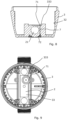
Figure 8 shown a cross-section of a flow meter housing, and -
Figure 9 shows another embodiment of an electronics housing of a flow meter. -
Fig. 1 shows anelectronic flow meter 1, such as a water meter for installation as part of a utility infrastructure. The electronic flow meter is configured for measuring fluid flow as well fluid pressure of a fluid flowing through the utility infrastructure. The flow meter comprises aflow tube 2 provided withflow channel 21 extending between aninlet 22 and anoutlet 23 adapted for being connected to the utility infrastructure and the piping system at a consumption side, respectively. - In the shown embodiment, an
electronics housing 3 and the flow tube are provided as a monolithic polymer structure, the flow tube being defined by a first wall and the housing being partly defined by a second circumferential wall forming a housing opening, wherein the first wall separates an inner bore of the flow tube from an inner compartment of the housing. However, in other embodiments, the electronics housing may be formed as a separate element and subsequently mounted on or otherwise connected to the flow tube. The electronics housing and/or flow tube is advantageously made by injection molding and of a polymer material, such as a glass fiber reinforced polyphenylene sulfide with a 20-40% fiber content. Additionally, the housing is closed off by a cover (not shown) configured for sealed engagement with the housing opening to provide a fluid-tight enclosure. - Inside the electronics housing a
flow sensor 4 is arranged. The flow sensor includes a pair ofultrasound transducer elements 41 mounted on a main printed circuit board (PCB) 42. The main PCB may be of a one- or more layer structure provided with surface mounted devices and/or circuits on one or both of its upwards- and downwards facing sides (421, 422). The flow sensor is configured for operating the ultrasound transducers to transmit and receive ultrasound signals through a fluid flow in the flow channel and to determine a flow rate of the fluid based on the time of flight of the transmitted and received ultrasound signals. - Additionally, a
pressure sensor 5 including asensor element 51 is arranged inside the electronics housing. A top-side 53 of the sensor element is arranged in fluid communication with the flow channel via asensor bore 31 provided in aninner surface 32 of the electronics housing. The sensor bore extends between the flow channel and the inside of the electronics housing through a wall of theflow tube 33 and the electronics housing. Further, abacking device 6 is provided to force the sensor element against asealing element 55 arranged to provide a fluid tight sealing between the sensor element and the inner surface of the electronic housing. - In one embodiment the sensor element is a ceramic sensor element and the ceramic pressure sensor is a capacitive sensor including layers of ceramic material provided with electrodes. The top-side of the sensor element is constituted by a layer of ceramic material functioning as a flexible sensor diaphragm deflecting dependent on the pressure of the sensed fluid. When the sensor is subjected to a fluid under pressure, the sensor diaphragm deflects and the distance between the electrodes is affect. The ceramic sensor diaphragm may additional be provided with a thin steel membrane or plate and a coating, such as a polytetrafluoroetylen (PTFE) coating, to protect the part of the sensor in contact with the fluid.
- Alternatively, the sensor element may be a micro electro-mechanical system sensor (MEMS sensor) or a strain gauge sensor using a plurality of strain gauges to measure changes in the strain of a diaphragm part of the sensor element. In one embodiment a strain gauge based sensor may comprise four strain gauges included in a Wheatstone Bridge circuitry. When diaphragm deflects the strain gauge cause a voltage output across the Wheatstone Bridge indicative of the pressure. As an alternative to foil strain gauges silicon piezoresistive technology or ceramic piezoresistive sensing technology may be used to detect changes in stain in the diaphragm part of the ceramic pressure element.
- By including both a pressure sensor and a flow sensor in the electronic flow meter, the meter may be configured to operate the pressure sensor dependent on the flow rate and the flow sensor dependent on the pressure. Detected changes in pressure may thus be used as a trigger for measuring the flow rate. Similar, changes in flow rate may be used as a trigger for measuring pressure. Especially, the flow sensor may be used to determine periods with no flow through the flow tube and the pressure sensor may be activated to measure pressure in these periods. Since flow in the flow tube affects pressure measurements, it is desirable to be able to correlate flow and pressure measurements and to be able to determine the flow at the time of a given pressure measurement.
- Referring to
Fig. 1 and 3 , one embodiment of the electronic flow meter including a sensor element mounted on themain PCB 42 is shown. The sensor element is mounted on the downwards facingside 421 of the main PCB arranged inside the electronics housing facing towards the flow tube. The sensor element is mounted as a surface-mounted device, i.e. placed directly onto the surface of the main PCB, during mounting of components on the PCB. This allows for a highly automated manufacturing process reducing complexity and cost. Anelectronic measurement circuit 52 associated with the sensor element is arranged on either the downwards facingside 421 or the opposite upper facing side 422 of the main PCB. The electronic measurement circuit is electrically connected to a central processing unit mounted on the main PCB and configured for transforming the response of the sensor element into a signal indicative of the pressure in the flow channel. - Above the sensor element, the main PCB is provided with cut-
outs 43 allowing the backing device to engage directly with the sensor element. Applying the pressure of the backing device directly to the sensor element allows for an increased compression pressure to be applied to the sealingelement 55 arranged between the sensor element and the inner surface of in the electronic housing. -
Fig. 4 -7 illustrates an embodiment of the electronic flow meter wherein the sensor element and its associated measurement circuit is mounted on a dedicated sensor printed circuit board (PCB) 54 electrically connected to the main PCB. The main PCB is provided with a cut-out 57 for receiving thesensor PCB 54 and asocket 59 for electrically connecting the sensor PCB to the main PCB. The sensor PCB includes a plug orcontact face 58, such an edge connector, configured for engaging the socket on the main PCB. When the sensor PCB is mounted in the socket, the sensor- and main PCBs are substantially arranged in the same plane, aligning a downwards facing surface of the sensor element and the ultrasound transducers. The cut-out for the sensor PCB is wider than the sensor PCB allowing the backing device to engage the sensor element. Alternatively, the sensor element may be arranged on the sensor PCB and measurement circuit associated with the sensor element may be arranged on the main PCB. - In the embodiments shown in
figures 1-3 and4-7 , respectively, the sealingelement 55 is arranged in acircular recess 332 provided in the inner surface of the electronics housing. A fluid chamber is thus provided between the ceramic pressure element and therecess 332, into which pressurized fluid from the flow tube may be introduced. As seen fromFig. 8 and Fig. 9 , adrain channel 7 may be provided to drain away any fluids that may escape the sealingelement 55. Adrain channel inlet 71 is provided outside a periphery of the sealing element. To contain and guide any fluids that might have escaped the sealing element towards the drain channel, an additional sealing element may be provided in acircumferential recess 333 provided around the circular recess providing the fluid chamber. The drain channel extends through the wall of the flow tube to anoutlet 72 provided in an external surface of the flow tube or electronics chamber. - The backing device includes a rigid
force carrying member 61 adapted for being joined with the electronics housing, e.g. by screws and corresponding bosses provided as in integrated part of the electronics housing.Studs 62 adapted to engage the sensor element extend for the for carrying member allowing a certain backing force to be applied to the sensor element. - Furthermore, the top-side sensor element may be provided with a protective membrane serving to prevent sedimentation on the sensor element. Such protective membrane may have a thickness from 100-500 microns only serving to protect the ceramic element without affecting sensor precision. The protective membrane may in one embodiment be an integrated part of the electronics housing formed by the same material as the electronic housing by through injection molding. Alternatively, the protective membrane may be arranged as an insert in the injection molded electronics housing.
- The electronic flow meter further comprises a self-contained power source, such as a battery pack (not shown) for powering the central processing unit, the flow sensor and the pressure sensor. The electronic flow meter may further include wireless communication means such as a radio device for communicating with external devices.
- As seen from
Fig. 1 and4 , the electronic flow meter further comprises a measuringtube 24 arranged in the flow channel. The measuring tube extends between the ultrasound transducer and in the shown embodiment, the measuring tube is mounted on areflector holding arrangement 8 serving to fixate a pair ofreflectors 81 in the flow channel. The reflectors reflect the ultrasound signals transmitted by the ultrasound transducers, such that the ultrasound signals are directed from the transmitting transducer to the opposite transducer being operated as a receiver. Extending along the flow channel, the measuring tube creates a narrow passage along an outer periphery of the flow channel adjacent to aninterior surface 25 of the flow tube. This narrow passage may be open in both ends such that a limited amount of fluid may flow on an outside of the measuring tube. Alternatively, the narrow passage may be closed at one end by a fluidtight connection 26 provided between the interior surface of the flow tube and an upstream or downstream end of the flow tube. - As seen from
Fig. 1 and4 , anopening 311 of the sensor bore is provided in theinterior surface 25 of the flow tube in the narrow passage between the flow tube wall and the measuring tube. By positioning the opening of the sensor bore in this area, the sensor bore and thus the pressure sensor is shielded from pressure surges occurring in the distribution network or the piping installation at the point of consumption. Such pressure surges, also known as water hammer, may be significant and cause sensors and other equipment to be damaged. Still, as the sensor bore is in direct fluid communication with the flow channel, the pressure in the sensor bores is equal to that of the flow channel. Additionally, as flow through the flow tube may affect the static and/or dynamic pressure in the flow tube, pressure measurements performed by the measurement circuit may be controlled by the central processing unit, dependent on the flow sensed via the flow sensor. The central processing unit may correlate flow data and sensor data to identify pressure measurements performed during either static flow conditions where no flow exists or the flow rate is insignificant and various flow conditions subject to different flow rates. - Above, various embodiment of an electronic flow meter including a pressure sensor has been described. The pressure sensor includes a sensor element and an associated electronic measurement circuit mounted on a dedicated sensor PCB. In further embodiments of an electronic flow meter according to the invention, other types of sensors may also be implemented on the dedicated sensor PCB. By providing a sensor on a dedicated sensor PCB electrically connected to the main PCB, e.g. by a socket and edge connectors, the electronic flow meter may easily be equipped with different types of sensors. This modular design also provides the advantage that different sensors may be incorporated into the electronic meter with minimal effect on the remaining parts of the meter electronics, such as the configuration of the main PCB, central processing unit and flow sensor. Other types of sensors may be sensors for measuring biological substances in a fluid, conductivity, such as a conductivity sensor configured for determining the chlorine concentration in a fluid or temperature. Such sensors may include different types of sensor elements mounted on the sensor PCB and dedicated measurement circuits.
- Although the present invention has been described in connection with the specified embodiments, it should not be construed as being in any way limited to the presented examples. The scope of the present invention is set out by the accompanying claim set. In the context of the claims, the terms "comprising" or "comprises" do not exclude other possible elements or steps. Also, the mentioning of references such as "a" or "an" etc. should not be construed as excluding a plurality. The use of reference signs in the claims with respect to elements indicated in the figures shall also not be construed as limiting the scope of the invention.
Claims (13)
- An electronic flow meter (1) comprising:- a flow tube (2) provided with flow channel (21) extending between an inlet (22) and an outlet (23)- an electronics housing (3) arranged in association with the flow tube, wherein a sensor bore (31) in fluid communication with the flow channel is provided in an inner surface (32) of the electronic housing;- a flow sensor (4) including a pair of ultrasound transducers (41) mounted on a main printed circuit board (42) arranged inside the electronics housing, the flow sensor being configured for measuring a flow rate of a fluid flowing through the flow tube,- a pressure sensor (5) including a sensor element (51) and an associated electronic measurement circuit (52);wherein a top-side (53) of the sensor element is arranged opposite the sensor bore in fluid communication with the flow channel via the sensor bore (31) and a backing device (6) is provided to force the sensor element against a sealing element (55) arranged to provide a sealing between the sensor element and the inner surface of in the electronic housing,characterized in that the electronic flowmeter further comprises a measuring tube (24) arranged in the flow channel (21) extending between the ultrasound transducers, and an opening (311) of the sensor bore (31) is provided in an interior surface (25) of the flow tube overlapped by the measuring tube, andextending along the flow channel, the measuring tube creates a narrow passage along an outer periphery of the flow channel adjacent to the interior surface (25) of the flow tube,and the opening (311) of the sensor bore is provided in the interior surface of the flow tube in the narrow passage between a flow tube wall and the measuring tube.
- The electronic flow meter according to claim 1, wherein the sensor element (51) is mounted on the main PCB or a dedicated sensor PCB (54) electrically connected to the main PCB.
- The electronic flow meter according to claim 1 or 2, wherein the sensor element (51) is mounted on a downwards facing side (421) of the main PCB arranged inside the electronics housing facing towards the flow tube together with two ultrasound transducer elements (41).
- The electronic flow meter according to any of the preceding claims, wherein the main PCB or the sensor PCB is provided with cut-outs (43) above parts of the sensor element (51) allowing the backing device to engage directly with the sensor element.
- The electronic flow meter according to any of the preceding claims, wherein the backing device includes a rigid force carrying members (61) provided with studs (62) adapted to engage with the sensor element (51).
- The electronic flow meter according to any of the preceding claims, wherein the top-side of the sensor element (51) is provided with a protective membrane having a thickness from 100-500 microns.
- The electronic flow meter according to any of the preceding claims, wherein the sensor element (51) is a ceramic sensor element.
- The electronic flow meter according to any of the preceding claims, wherein the sensor element (51) is a ceramic capacitive pressure element responsive to changes in ambient pressure.
- The electronic flow meter according to any of the preceding claims, wherein the sensor bore extends through the wall(s) (33) of the flow tube and electronic housing.
- The electronic flow meter according to any of the preceding claims, wherein the flow meter further comprises a central processing unit mounted on the printed circuit board, the flow sensor and the pressure sensor being electrically connected to the central processing unit.
- The electronic flow meter according to any of the preceding claims, wherein the flow meter further comprises a self-contained power source for powering the central processing unit, the flow sensor and the pressure sensor.
- The electronic flow meter according to any of the preceding claims, wherein a fluid tight connection (26) is provided between the interior surface of the flow tube and an upstream or downstream end of the measuring tube.
- The electronic flow meter according to any of the preceding claims, wherein the electronics housing and the flow tube are provided as a monolithic polymer structure.
Applications Claiming Priority (2)
| Application Number | Priority Date | Filing Date | Title |
|---|---|---|---|
| DKPA201870666 | 2018-10-11 | ||
| PCT/DK2019/050313 WO2020074050A1 (en) | 2018-10-11 | 2019-10-11 | Electronic flow meter with pressure sensor |
Publications (3)
| Publication Number | Publication Date |
|---|---|
| EP3864379A1 EP3864379A1 (en) | 2021-08-18 |
| EP3864379C0 EP3864379C0 (en) | 2024-06-26 |
| EP3864379B1 true EP3864379B1 (en) | 2024-06-26 |
Family
ID=68295908
Family Applications (1)
| Application Number | Title | Priority Date | Filing Date |
|---|---|---|---|
| EP19790453.5A Active EP3864379B1 (en) | 2018-10-11 | 2019-10-11 | Electronic flow meter with pressure sensor |
Country Status (2)
| Country | Link |
|---|---|
| EP (1) | EP3864379B1 (en) |
| WO (1) | WO2020074050A1 (en) |
Families Citing this family (4)
| Publication number | Priority date | Publication date | Assignee | Title |
|---|---|---|---|---|
| CN114061677B (en) * | 2021-11-27 | 2024-09-20 | 觉隆传感技术(深圳)有限公司 | Multi-channel large-caliber ultrasonic water meter with layered layout of column type transducers |
| IT202200002867A1 (en) * | 2022-02-16 | 2023-08-16 | Pietro Fiorentini Spa | Improved device for measuring a fluid, preferably a liquid. |
| US12292317B2 (en) * | 2022-02-28 | 2025-05-06 | Mueller International, Llc | Ultrasonic flow meter assembly |
| US12281925B2 (en) * | 2022-05-31 | 2025-04-22 | Itron Global Sarl | Pressure sensor embedded in a metering device |
Citations (2)
| Publication number | Priority date | Publication date | Assignee | Title |
|---|---|---|---|---|
| DE19713526A1 (en) * | 1997-04-01 | 1998-10-08 | Elster Produktion Gmbh | Device for ultrasonic flow measurement |
| JP2017096979A (en) * | 2017-01-30 | 2017-06-01 | 愛知時計電機株式会社 | Ultrasonic flowmeter |
Family Cites Families (5)
| Publication number | Priority date | Publication date | Assignee | Title |
|---|---|---|---|---|
| DE102004061404A1 (en) * | 2004-12-21 | 2006-07-06 | Robert Bosch Gmbh | Ultrasonic flow meter and method for flow measurement by means of ultrasound |
| EP2130004A1 (en) * | 2006-10-31 | 2009-12-09 | IMI Vision Limited | Ultrasonic flow-rate measurement device and system |
| DE102012209149A1 (en) * | 2012-05-31 | 2013-12-05 | Robert Bosch Gmbh | Ultrasonic sensor e.g. ultrasonic flow meter for detecting property of fluid medium in air tract of engine of motor vehicle, has flow control element which is comprised in upstream and downstream of measuring element |
| US10746580B2 (en) * | 2016-07-13 | 2020-08-18 | Gwf Messsysteme Ag | Flow meter with measuring channel |
| EP3367074A1 (en) * | 2017-02-23 | 2018-08-29 | Kamstrup A/S | Electronic flow meter including a built-in pressure sensor |
-
2019
- 2019-10-11 WO PCT/DK2019/050313 patent/WO2020074050A1/en not_active Ceased
- 2019-10-11 EP EP19790453.5A patent/EP3864379B1/en active Active
Patent Citations (2)
| Publication number | Priority date | Publication date | Assignee | Title |
|---|---|---|---|---|
| DE19713526A1 (en) * | 1997-04-01 | 1998-10-08 | Elster Produktion Gmbh | Device for ultrasonic flow measurement |
| JP2017096979A (en) * | 2017-01-30 | 2017-06-01 | 愛知時計電機株式会社 | Ultrasonic flowmeter |
Also Published As
| Publication number | Publication date |
|---|---|
| EP3864379A1 (en) | 2021-08-18 |
| WO2020074050A1 (en) | 2020-04-16 |
| EP3864379C0 (en) | 2024-06-26 |
Similar Documents
| Publication | Publication Date | Title |
|---|---|---|
| EP2414788B1 (en) | Flow meter unit with water-tight casing | |
| WO2020074050A1 (en) | Electronic flow meter with pressure sensor | |
| JP3323513B2 (en) | Pressure sensor module with non-polluting body | |
| CN101495846B (en) | Redundant mechanical and electronic remote seal system | |
| RU2487329C2 (en) | Metering pressure converter, method to monitor condition of metering pressure converter and pressure sensor | |
| US7401522B2 (en) | Pressure sensor using compressible sensor body | |
| US9869600B2 (en) | Pressure sensor | |
| CN105258742B (en) | Ultrasonic consumption meter with locking mechanism | |
| US5672832A (en) | Chemically inert flow meter within caustic fluids having non-contaminating body | |
| US5072190A (en) | Pressure sensing device having fill fluid contamination detector | |
| CA2625102A1 (en) | Apparatus and method for detecting fluid entering a wellbore | |
| CN110017861B (en) | Embedded sensor and fluid line system | |
| WO1997030333A8 (en) | Flow meter within caustic fluids having non-contaminating body | |
| EP3488192B1 (en) | Vortex flowmeter with reduced process intrusion | |
| EP3367074A1 (en) | Electronic flow meter including a built-in pressure sensor | |
| CN106471193A (en) | Pressure sensor apparatus for common network | |
| US10048149B2 (en) | Relative pressure sensor | |
| CN101273257B (en) | Pressure transmitter with sound pressure sensor | |
| KR101865801B1 (en) | Inline-type apparatus for remotely measuring pressure and flow in water pipe | |
| JPH10197316A (en) | Density corrected liquid level detector | |
| KR20240008521A (en) | Water Leak Sensor Using Hetero Piezoelectric Element | |
| WO2000025102A1 (en) | Device for measuring a medium under pressure | |
| JP4882369B2 (en) | Air pressure detection system | |
| CN219757419U (en) | Ultrasonic flowmeter | |
| KR100687261B1 (en) | Differential pressure flow meter |
Legal Events
| Date | Code | Title | Description |
|---|---|---|---|
| STAA | Information on the status of an ep patent application or granted ep patent |
Free format text: STATUS: UNKNOWN |
|
| STAA | Information on the status of an ep patent application or granted ep patent |
Free format text: STATUS: THE INTERNATIONAL PUBLICATION HAS BEEN MADE |
|
| PUAI | Public reference made under article 153(3) epc to a published international application that has entered the european phase |
Free format text: ORIGINAL CODE: 0009012 |
|
| STAA | Information on the status of an ep patent application or granted ep patent |
Free format text: STATUS: REQUEST FOR EXAMINATION WAS MADE |
|
| 17P | Request for examination filed |
Effective date: 20210507 |
|
| AK | Designated contracting states |
Kind code of ref document: A1 Designated state(s): AL AT BE BG CH CY CZ DE DK EE ES FI FR GB GR HR HU IE IS IT LI LT LU LV MC MK MT NL NO PL PT RO RS SE SI SK SM TR |
|
| DAV | Request for validation of the european patent (deleted) | ||
| DAX | Request for extension of the european patent (deleted) | ||
| GRAP | Despatch of communication of intention to grant a patent |
Free format text: ORIGINAL CODE: EPIDOSNIGR1 |
|
| STAA | Information on the status of an ep patent application or granted ep patent |
Free format text: STATUS: GRANT OF PATENT IS INTENDED |
|
| INTG | Intention to grant announced |
Effective date: 20230907 |
|
| GRAJ | Information related to disapproval of communication of intention to grant by the applicant or resumption of examination proceedings by the epo deleted |
Free format text: ORIGINAL CODE: EPIDOSDIGR1 |
|
| STAA | Information on the status of an ep patent application or granted ep patent |
Free format text: STATUS: REQUEST FOR EXAMINATION WAS MADE |
|
| GRAP | Despatch of communication of intention to grant a patent |
Free format text: ORIGINAL CODE: EPIDOSNIGR1 |
|
| STAA | Information on the status of an ep patent application or granted ep patent |
Free format text: STATUS: GRANT OF PATENT IS INTENDED |
|
| INTC | Intention to grant announced (deleted) | ||
| INTG | Intention to grant announced |
Effective date: 20240124 |
|
| GRAS | Grant fee paid |
Free format text: ORIGINAL CODE: EPIDOSNIGR3 |
|
| GRAA | (expected) grant |
Free format text: ORIGINAL CODE: 0009210 |
|
| STAA | Information on the status of an ep patent application or granted ep patent |
Free format text: STATUS: THE PATENT HAS BEEN GRANTED |
|
| AK | Designated contracting states |
Kind code of ref document: B1 Designated state(s): AL AT BE BG CH CY CZ DE DK EE ES FI FR GB GR HR HU IE IS IT LI LT LU LV MC MK MT NL NO PL PT RO RS SE SI SK SM TR |
|
| REG | Reference to a national code |
Ref country code: GB Ref legal event code: FG4D |
|
| REG | Reference to a national code |
Ref country code: CH Ref legal event code: EP |
|
| REG | Reference to a national code |
Ref country code: DE Ref legal event code: R096 Ref document number: 602019054273 Country of ref document: DE |
|
| U01 | Request for unitary effect filed |
Effective date: 20240711 |
|
| U07 | Unitary effect registered |
Designated state(s): AT BE BG DE DK EE FI FR IT LT LU LV MT NL PT SE SI Effective date: 20240725 |
|
| PG25 | Lapsed in a contracting state [announced via postgrant information from national office to epo] |
Ref country code: HR Free format text: LAPSE BECAUSE OF FAILURE TO SUBMIT A TRANSLATION OF THE DESCRIPTION OR TO PAY THE FEE WITHIN THE PRESCRIBED TIME-LIMIT Effective date: 20240626 |
|
| PG25 | Lapsed in a contracting state [announced via postgrant information from national office to epo] |
Ref country code: GR Free format text: LAPSE BECAUSE OF FAILURE TO SUBMIT A TRANSLATION OF THE DESCRIPTION OR TO PAY THE FEE WITHIN THE PRESCRIBED TIME-LIMIT Effective date: 20240927 |
|
| PG25 | Lapsed in a contracting state [announced via postgrant information from national office to epo] |
Ref country code: NO Free format text: LAPSE BECAUSE OF FAILURE TO SUBMIT A TRANSLATION OF THE DESCRIPTION OR TO PAY THE FEE WITHIN THE PRESCRIBED TIME-LIMIT Effective date: 20240926 Ref country code: HR Free format text: LAPSE BECAUSE OF FAILURE TO SUBMIT A TRANSLATION OF THE DESCRIPTION OR TO PAY THE FEE WITHIN THE PRESCRIBED TIME-LIMIT Effective date: 20240626 Ref country code: GR Free format text: LAPSE BECAUSE OF FAILURE TO SUBMIT A TRANSLATION OF THE DESCRIPTION OR TO PAY THE FEE WITHIN THE PRESCRIBED TIME-LIMIT Effective date: 20240927 Ref country code: RS Free format text: LAPSE BECAUSE OF FAILURE TO SUBMIT A TRANSLATION OF THE DESCRIPTION OR TO PAY THE FEE WITHIN THE PRESCRIBED TIME-LIMIT Effective date: 20240926 |
|
| U20 | Renewal fee for the european patent with unitary effect paid |
Year of fee payment: 6 Effective date: 20241025 |
|
| PG25 | Lapsed in a contracting state [announced via postgrant information from national office to epo] |
Ref country code: PL Free format text: LAPSE BECAUSE OF FAILURE TO SUBMIT A TRANSLATION OF THE DESCRIPTION OR TO PAY THE FEE WITHIN THE PRESCRIBED TIME-LIMIT Effective date: 20240626 |
|
| PG25 | Lapsed in a contracting state [announced via postgrant information from national office to epo] |
Ref country code: IS Free format text: LAPSE BECAUSE OF FAILURE TO SUBMIT A TRANSLATION OF THE DESCRIPTION OR TO PAY THE FEE WITHIN THE PRESCRIBED TIME-LIMIT Effective date: 20241026 |
|
| PG25 | Lapsed in a contracting state [announced via postgrant information from national office to epo] |
Ref country code: CZ Free format text: LAPSE BECAUSE OF FAILURE TO SUBMIT A TRANSLATION OF THE DESCRIPTION OR TO PAY THE FEE WITHIN THE PRESCRIBED TIME-LIMIT Effective date: 20240626 |
|
| PG25 | Lapsed in a contracting state [announced via postgrant information from national office to epo] |
Ref country code: RO Free format text: LAPSE BECAUSE OF FAILURE TO SUBMIT A TRANSLATION OF THE DESCRIPTION OR TO PAY THE FEE WITHIN THE PRESCRIBED TIME-LIMIT Effective date: 20240626 Ref country code: SK Free format text: LAPSE BECAUSE OF FAILURE TO SUBMIT A TRANSLATION OF THE DESCRIPTION OR TO PAY THE FEE WITHIN THE PRESCRIBED TIME-LIMIT Effective date: 20240626 |
|
| PG25 | Lapsed in a contracting state [announced via postgrant information from national office to epo] |
Ref country code: SM Free format text: LAPSE BECAUSE OF FAILURE TO SUBMIT A TRANSLATION OF THE DESCRIPTION OR TO PAY THE FEE WITHIN THE PRESCRIBED TIME-LIMIT Effective date: 20240626 Ref country code: ES Free format text: LAPSE BECAUSE OF FAILURE TO SUBMIT A TRANSLATION OF THE DESCRIPTION OR TO PAY THE FEE WITHIN THE PRESCRIBED TIME-LIMIT Effective date: 20240626 |
|
| PG25 | Lapsed in a contracting state [announced via postgrant information from national office to epo] |
Ref country code: SM Free format text: LAPSE BECAUSE OF FAILURE TO SUBMIT A TRANSLATION OF THE DESCRIPTION OR TO PAY THE FEE WITHIN THE PRESCRIBED TIME-LIMIT Effective date: 20240626 Ref country code: SK Free format text: LAPSE BECAUSE OF FAILURE TO SUBMIT A TRANSLATION OF THE DESCRIPTION OR TO PAY THE FEE WITHIN THE PRESCRIBED TIME-LIMIT Effective date: 20240626 Ref country code: RO Free format text: LAPSE BECAUSE OF FAILURE TO SUBMIT A TRANSLATION OF THE DESCRIPTION OR TO PAY THE FEE WITHIN THE PRESCRIBED TIME-LIMIT Effective date: 20240626 Ref country code: PL Free format text: LAPSE BECAUSE OF FAILURE TO SUBMIT A TRANSLATION OF THE DESCRIPTION OR TO PAY THE FEE WITHIN THE PRESCRIBED TIME-LIMIT Effective date: 20240626 Ref country code: IS Free format text: LAPSE BECAUSE OF FAILURE TO SUBMIT A TRANSLATION OF THE DESCRIPTION OR TO PAY THE FEE WITHIN THE PRESCRIBED TIME-LIMIT Effective date: 20241026 Ref country code: ES Free format text: LAPSE BECAUSE OF FAILURE TO SUBMIT A TRANSLATION OF THE DESCRIPTION OR TO PAY THE FEE WITHIN THE PRESCRIBED TIME-LIMIT Effective date: 20240626 Ref country code: CZ Free format text: LAPSE BECAUSE OF FAILURE TO SUBMIT A TRANSLATION OF THE DESCRIPTION OR TO PAY THE FEE WITHIN THE PRESCRIBED TIME-LIMIT Effective date: 20240626 |
|
| PLBE | No opposition filed within time limit |
Free format text: ORIGINAL CODE: 0009261 |
|
| STAA | Information on the status of an ep patent application or granted ep patent |
Free format text: STATUS: NO OPPOSITION FILED WITHIN TIME LIMIT |
|
| REG | Reference to a national code |
Ref country code: CH Ref legal event code: PL |
|
| 26N | No opposition filed |
Effective date: 20250327 |
|
| GBPC | Gb: european patent ceased through non-payment of renewal fee |
Effective date: 20241011 |
|
| PG25 | Lapsed in a contracting state [announced via postgrant information from national office to epo] |
Ref country code: MC Free format text: LAPSE BECAUSE OF FAILURE TO SUBMIT A TRANSLATION OF THE DESCRIPTION OR TO PAY THE FEE WITHIN THE PRESCRIBED TIME-LIMIT Effective date: 20240626 |
|
| PG25 | Lapsed in a contracting state [announced via postgrant information from national office to epo] |
Ref country code: GB Free format text: LAPSE BECAUSE OF NON-PAYMENT OF DUE FEES Effective date: 20241011 |
|
| PG25 | Lapsed in a contracting state [announced via postgrant information from national office to epo] |
Ref country code: CH Free format text: LAPSE BECAUSE OF NON-PAYMENT OF DUE FEES Effective date: 20241031 |
|
| PG25 | Lapsed in a contracting state [announced via postgrant information from national office to epo] |
Ref country code: IE Free format text: LAPSE BECAUSE OF NON-PAYMENT OF DUE FEES Effective date: 20241011 |
|
| U20 | Renewal fee for the european patent with unitary effect paid |
Year of fee payment: 7 Effective date: 20251028 |
|
| PG25 | Lapsed in a contracting state [announced via postgrant information from national office to epo] |
Ref country code: CY Free format text: LAPSE BECAUSE OF FAILURE TO SUBMIT A TRANSLATION OF THE DESCRIPTION OR TO PAY THE FEE WITHIN THE PRESCRIBED TIME-LIMIT; INVALID AB INITIO Effective date: 20191011 |
|
| PG25 | Lapsed in a contracting state [announced via postgrant information from national office to epo] |
Ref country code: HU Free format text: LAPSE BECAUSE OF FAILURE TO SUBMIT A TRANSLATION OF THE DESCRIPTION OR TO PAY THE FEE WITHIN THE PRESCRIBED TIME-LIMIT; INVALID AB INITIO Effective date: 20191011 |