EP3864325B1 - Smart valve with integrated electronics - Google Patents
Smart valve with integrated electronics Download PDFInfo
- Publication number
- EP3864325B1 EP3864325B1 EP19797903.2A EP19797903A EP3864325B1 EP 3864325 B1 EP3864325 B1 EP 3864325B1 EP 19797903 A EP19797903 A EP 19797903A EP 3864325 B1 EP3864325 B1 EP 3864325B1
- Authority
- EP
- European Patent Office
- Prior art keywords
- valve
- electronics module
- data
- sensors
- valve stem
- Prior art date
- Legal status (The legal status is an assumption and is not a legal conclusion. Google has not performed a legal analysis and makes no representation as to the accuracy of the status listed.)
- Active
Links
Images



Classifications
-
- F—MECHANICAL ENGINEERING; LIGHTING; HEATING; WEAPONS; BLASTING
- F15—FLUID-PRESSURE ACTUATORS; HYDRAULICS OR PNEUMATICS IN GENERAL
- F15B—SYSTEMS ACTING BY MEANS OF FLUIDS IN GENERAL; FLUID-PRESSURE ACTUATORS, e.g. SERVOMOTORS; DETAILS OF FLUID-PRESSURE SYSTEMS, NOT OTHERWISE PROVIDED FOR
- F15B19/00—Testing; Calibrating; Fault detection or monitoring; Simulation or modelling of fluid-pressure systems or apparatus not otherwise provided for
- F15B19/005—Fault detection or monitoring
-
- F—MECHANICAL ENGINEERING; LIGHTING; HEATING; WEAPONS; BLASTING
- F16—ENGINEERING ELEMENTS AND UNITS; GENERAL MEASURES FOR PRODUCING AND MAINTAINING EFFECTIVE FUNCTIONING OF MACHINES OR INSTALLATIONS; THERMAL INSULATION IN GENERAL
- F16K—VALVES; TAPS; COCKS; ACTUATING-FLOATS; DEVICES FOR VENTING OR AERATING
- F16K1/00—Lift valves or globe valves, i.e. cut-off apparatus with closure members having at least a component of their opening and closing motion perpendicular to the closing faces
- F16K1/16—Lift valves or globe valves, i.e. cut-off apparatus with closure members having at least a component of their opening and closing motion perpendicular to the closing faces with pivoted closure-members
- F16K1/18—Lift valves or globe valves, i.e. cut-off apparatus with closure members having at least a component of their opening and closing motion perpendicular to the closing faces with pivoted closure-members with pivoted discs or flaps
- F16K1/22—Lift valves or globe valves, i.e. cut-off apparatus with closure members having at least a component of their opening and closing motion perpendicular to the closing faces with pivoted closure-members with pivoted discs or flaps with axis of rotation crossing the valve member, e.g. butterfly valves
- F16K1/221—Lift valves or globe valves, i.e. cut-off apparatus with closure members having at least a component of their opening and closing motion perpendicular to the closing faces with pivoted closure-members with pivoted discs or flaps with axis of rotation crossing the valve member, e.g. butterfly valves specially adapted operating means therefor
-
- F—MECHANICAL ENGINEERING; LIGHTING; HEATING; WEAPONS; BLASTING
- F16—ENGINEERING ELEMENTS AND UNITS; GENERAL MEASURES FOR PRODUCING AND MAINTAINING EFFECTIVE FUNCTIONING OF MACHINES OR INSTALLATIONS; THERMAL INSULATION IN GENERAL
- F16K—VALVES; TAPS; COCKS; ACTUATING-FLOATS; DEVICES FOR VENTING OR AERATING
- F16K1/00—Lift valves or globe valves, i.e. cut-off apparatus with closure members having at least a component of their opening and closing motion perpendicular to the closing faces
- F16K1/16—Lift valves or globe valves, i.e. cut-off apparatus with closure members having at least a component of their opening and closing motion perpendicular to the closing faces with pivoted closure-members
- F16K1/18—Lift valves or globe valves, i.e. cut-off apparatus with closure members having at least a component of their opening and closing motion perpendicular to the closing faces with pivoted closure-members with pivoted discs or flaps
- F16K1/22—Lift valves or globe valves, i.e. cut-off apparatus with closure members having at least a component of their opening and closing motion perpendicular to the closing faces with pivoted closure-members with pivoted discs or flaps with axis of rotation crossing the valve member, e.g. butterfly valves
-
- F—MECHANICAL ENGINEERING; LIGHTING; HEATING; WEAPONS; BLASTING
- F16—ENGINEERING ELEMENTS AND UNITS; GENERAL MEASURES FOR PRODUCING AND MAINTAINING EFFECTIVE FUNCTIONING OF MACHINES OR INSTALLATIONS; THERMAL INSULATION IN GENERAL
- F16K—VALVES; TAPS; COCKS; ACTUATING-FLOATS; DEVICES FOR VENTING OR AERATING
- F16K1/00—Lift valves or globe valves, i.e. cut-off apparatus with closure members having at least a component of their opening and closing motion perpendicular to the closing faces
- F16K1/16—Lift valves or globe valves, i.e. cut-off apparatus with closure members having at least a component of their opening and closing motion perpendicular to the closing faces with pivoted closure-members
- F16K1/18—Lift valves or globe valves, i.e. cut-off apparatus with closure members having at least a component of their opening and closing motion perpendicular to the closing faces with pivoted closure-members with pivoted discs or flaps
- F16K1/22—Lift valves or globe valves, i.e. cut-off apparatus with closure members having at least a component of their opening and closing motion perpendicular to the closing faces with pivoted closure-members with pivoted discs or flaps with axis of rotation crossing the valve member, e.g. butterfly valves
- F16K1/222—Shaping of the valve member
-
- F—MECHANICAL ENGINEERING; LIGHTING; HEATING; WEAPONS; BLASTING
- F16—ENGINEERING ELEMENTS AND UNITS; GENERAL MEASURES FOR PRODUCING AND MAINTAINING EFFECTIVE FUNCTIONING OF MACHINES OR INSTALLATIONS; THERMAL INSULATION IN GENERAL
- F16K—VALVES; TAPS; COCKS; ACTUATING-FLOATS; DEVICES FOR VENTING OR AERATING
- F16K31/00—Actuating devices; Operating means; Releasing devices
- F16K31/02—Actuating devices; Operating means; Releasing devices electric; magnetic
- F16K31/04—Actuating devices; Operating means; Releasing devices electric; magnetic using a motor
-
- F—MECHANICAL ENGINEERING; LIGHTING; HEATING; WEAPONS; BLASTING
- F16—ENGINEERING ELEMENTS AND UNITS; GENERAL MEASURES FOR PRODUCING AND MAINTAINING EFFECTIVE FUNCTIONING OF MACHINES OR INSTALLATIONS; THERMAL INSULATION IN GENERAL
- F16K—VALVES; TAPS; COCKS; ACTUATING-FLOATS; DEVICES FOR VENTING OR AERATING
- F16K37/00—Special means in or on valves or other cut-off apparatus for indicating or recording operation thereof, or for enabling an alarm to be given
- F16K37/0025—Electrical or magnetic means
- F16K37/0041—Electrical or magnetic means for measuring valve parameters
-
- F—MECHANICAL ENGINEERING; LIGHTING; HEATING; WEAPONS; BLASTING
- F16—ENGINEERING ELEMENTS AND UNITS; GENERAL MEASURES FOR PRODUCING AND MAINTAINING EFFECTIVE FUNCTIONING OF MACHINES OR INSTALLATIONS; THERMAL INSULATION IN GENERAL
- F16K—VALVES; TAPS; COCKS; ACTUATING-FLOATS; DEVICES FOR VENTING OR AERATING
- F16K37/00—Special means in or on valves or other cut-off apparatus for indicating or recording operation thereof, or for enabling an alarm to be given
- F16K37/0025—Electrical or magnetic means
- F16K37/005—Electrical or magnetic means for measuring fluid parameters
-
- G—PHYSICS
- G05—CONTROLLING; REGULATING
- G05D—SYSTEMS FOR CONTROLLING OR REGULATING NON-ELECTRIC VARIABLES
- G05D15/00—Control of mechanical force or stress; Control of mechanical pressure
- G05D15/01—Control of mechanical force or stress; Control of mechanical pressure characterised by the use of electric means
-
- F—MECHANICAL ENGINEERING; LIGHTING; HEATING; WEAPONS; BLASTING
- F15—FLUID-PRESSURE ACTUATORS; HYDRAULICS OR PNEUMATICS IN GENERAL
- F15B—SYSTEMS ACTING BY MEANS OF FLUIDS IN GENERAL; FLUID-PRESSURE ACTUATORS, e.g. SERVOMOTORS; DETAILS OF FLUID-PRESSURE SYSTEMS, NOT OTHERWISE PROVIDED FOR
- F15B2211/00—Circuits for servomotor systems
- F15B2211/60—Circuit components or control therefor
- F15B2211/63—Electronic controllers
- F15B2211/6303—Electronic controllers using input signals
- F15B2211/634—Electronic controllers using input signals representing a state of a valve
Definitions
- the sensors 25 may be in data and power communication with the electronics module 20 via wire or cables 84, or alternatively, may be in wireless data communication with or welded/attached/connected directly to the electronics module 20 in other exemplary embodiments.
- the sensors 25 may also alternatively be powered by battery (not illustrated, and may be external or internal).
- the valve body 82 may be hollow and the electronics module 20 (including microprocessor 23 and sensors 25), may be located within the hollowed valve body 82, and a conductor 21 may connect the electronics module 20 to the actuator 15.
- any description or disclosure regarding analysis and processing based on sensor 25 retrieved/observed data, measurements or metrics 60 that is described as performed by the microprocessor 23 may also be performed by remotely and also by microprocessors 16a or 17a within the actuators 15, as the primary conductor 21 relays, transmits and communicates data 60 between the actuator 15 and the electronics module 20 which contains the microprocessor 23.
- the microprocessor 23 and its components are generally implemented as electronic circuitry and processor-based computational components controlled by computer instructions stored in physical data storage components 50, including various types of electronic memory and/or mass-storage devices. It should be noted, at the onset, that computer instructions stored in physical data storage devices 50 and executed within processors or microcontrollers 23 comprise the control components of a wide variety of modern devices, machines, and systems, and are as tangible, physical, and real as any other component of a device, machine, or system. Occasionally, statements are encountered that suggest that computer-instruction-implemented control logic is "merely software" or something abstract and less tangible than physical machine components. Those familiar with modern science and technology understand that this is not the case. Computer instructions executed by processors must be physical entities stored in physical devices.
- the data 60 may be collected and analyzed both singularly and collectively to determine faults, predicted faults, comparison to base line readings, and others using statistical models such as Bayesian decision making and fine analysis of raw data 60 using Fast Fourier Transforms (hereinafter, also "FFT").
- FFT Fast Fourier Transforms
- the computations may be distributed between the microprocessors 23 and other computing units or electronics within the actuator 15 (such as microprocessors 16a or 17a).
- the various embodiments may be embodied in an electrical, optical, acoustical or other form of propagated signal (e.g., carrier waves, infrared signals, digital signals, etc.), or wire line, wireless, or other communications/telemetry medium.
- propagated signal e.g., carrier waves, infrared signals, digital signals, etc.
- wire line e.g., wireless, or other communications/telemetry medium.
- the risk assessment or analysis unit 52 may receive the categorized data 60 from the data collection unit 51 in order to determine if there is any present or future risk likely at the smart valve 10 and may make predictions not limited to remaining valve life, remaining actuator life, service intervals, potential pending failure or loss of service, and preventative maintenance. The risk may be based on real time events that are taking place in the operations and/or based on predictive events that are likely to occur.
- the risk assessment or analysis unit 23 may classify the risks for the microprocessor 23 and/or the operator (such as whether to create an alert or alarm). By way of example only, techniques such as Fourier analysis of data 60 from the vibration sensor 31 can extract differences in fundamental frequencies that can show shifts in baseline performance measured at commissioning compared to long term operation.
Landscapes
- Engineering & Computer Science (AREA)
- General Engineering & Computer Science (AREA)
- Mechanical Engineering (AREA)
- Physics & Mathematics (AREA)
- Fluid Mechanics (AREA)
- General Physics & Mathematics (AREA)
- Automation & Control Theory (AREA)
- Indication Of The Valve Opening Or Closing Status (AREA)
Description
- Not Applicable.
- Not Applicable.
- Technical field: The subject matter generally relates to apparatus and techniques for monitoring and managing industrial process control systems, in particular the underlying valves and actuators. The subject matter further relates to predictive analysis based on the monitored characteristics of the underlying valves and actuators of industrial process control systems. From
DE 20 2018 101 944 U1 ,DE 10 2016 215156 A1 ,EP 2 385 280 A1 ,US 5 616 829 A , andUS 6 240 789 B1 valves are known, which comprise a sensor for measuring characteristics of the valve. - The overall performance of the process of the industrial process control system can be characterized by monitoring key metrics tied to the process. Key metrics can be measured both directly and indirectly with advantages and disadvantages inherent to both techniques. Indirect measurements are conventionally used in attempt to obtain empirical data through a process of deduction. As an example, actuator operating torque on an electric actuator can be deduced by monitoring the motor current. Valve wear can be deduced by obtaining a baseline vibration measurement by comparing this measurement to vibration overtime. Direct measurement techniques are the most desirable but also the most impractical and have not thus far been successfully commercially implemented in practice. It is important to understand valve torque and to characterize it overtime to better understand how the valve is performing in the process. Measuring valve torque directly has been conventionally impractical.
- The valve stem which is attached to the valve is directly engaged with the actuator making it very difficult to couple a load cell or other device to directly measure torque. The challenges when monitoring key metrics of a control valve include the placement of the sensors, providing power to the sensors, and processing data from the sensors. Therefore, a need exists for an apparatus and a technique that can provide direct measurement of key metrics that have been conventionally very difficult to obtain and measure given the physical constraints of a control valve.
- The embodiments disclosed herein relate to an apparatus for monitoring a valve, as defined in appended independent claim 1, and having a control element, wherein the control element is actuated by an actuator, including a valve stem having a bore therethrough, wherein the bore is defined by a wall of the valve stem, and further wherein the valve stem is connected at a first end to the actuator and at a second end to the control element; and an electronics module within the bore of the valve stem, wherein the electronics module further includes a microprocessor and one or more sensors within the valve stem. Another embodiment disclosed herein relates to an apparatus for monitoring a valve as defined in appended independent claim 5. Furthermore, a method as defined in appended independent claim 8 is also disclosed.
- The embodiments may be better understood, and numerous objects, features, and advantages made apparent to those skilled in the art by referencing the accompanying drawings. These drawings are used to illustrate only typical embodiments of this invention, and are not to be considered limiting of its scope, for the invention may admit to other equally effective embodiments. The figures are not necessarily to scale and certain features and certain views of the figures may be shown exaggerated in scale or in schematic in the interest of clarity and conciseness.
-
FIG. 1 depicts a schematic diagram of an exemplary embodiment of a smart valve with an integrated electronics module and actuator. -
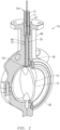
FIG. 2 depicts a partially cut away view of an exemplary embodiment of a smart valve having an integrated electronics module. -
FIG. 3 depicts an isometric side view of an exemplary embodiment of a smart valve having an electric actuator and an integrated electronics module. -
FIG. 4 depicts an isometric side view of an exemplary embodiment of a smart valve having of a pneumatic actuator and an integrated electronics module. -
FIG. 5 depicts a schematic diagram of an exemplary embodiment of an integrated electronics module. -
FIG. 6 depicts a block diagram of an exemplary embodiment of an integrated electronics module. -
FIG. 7 depicts a schematic diagram of an exemplary embodiment of a microcontroller or microprocessor for smart valve and integrated electronics module system. -
FIG. 8 depicts a schematic diagram of an alternate exemplary embodiment of a smart valve with an integrated electronics module and actuator. -
FIG. 9 depicts a partial front perspective view of an exemplary embodiment of a valve stem defining a bore for a smart valve and integrated electronics module system. -
FIG. 10 depicts a partial front perspective view of an exemplary embodiment of a valve stem defining a slot for a smart valve and integrated electronics module system. -
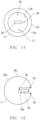
FIG. 11 depicts a cross sectional lateral view of a schematic diagram of an exemplary embodiment of a valve stem defining a bore for a smart valve and integrated electronics module system. -
FIG. 12 depicts a cross sectional lateral view of a schematic diagram of an exemplary embodiment of a valve stem defining a slot for a smart valve and integrated electronics module system. - The description that follows includes exemplary apparatus, methods, techniques, and instruction sequences that embody techniques of the inventive subject matter. However, it is understood that the described embodiments may be practiced without these specific details.
-
FIG. 1 depicts a schematic diagram of an exemplary embodiment of an improved valve, smart valve, orsmart valve system 10 with an integratedelectronics module 20 andactuator 15.FIG. 2 depicts a partially cut away view of an exemplary embodiment of asmart valve 10 having an integratedelectronics module 20. The challenges when designing a valve apparatus orsystem 10 to monitor key metrics which characterize the performance and wear of acontrol valve 10 include: the placement of thesensors 25, providing power to the sensors, andprocessing data 60 received from thesensors 25. Additionally, ifsensors 25 are placed on avalve stem 11 or avalve 10, there has not previously been an effective solution providing the necessary data communication and power connection between thesensors 25 and microcontrollers ormicroprocessors 23 capable of receiving and processing thesensor data 60. - By way of example only, in the exemplary embodiments as shown in
FIGs. 1 and2 , the disclosure proposes embedding anelectronics module 20 inside a cavity or hollow 90 of avalve stem 11 to address the challenge of placingsensors 25 on avalve 10 for direct measurement ofkey metrics 60. A conventional valve stem may be a solid metal cylinder which applies the acting force on the underlying valve. The solid stem may typically be used to reduce manufacturing cost but in terms of mechanical strength, avalve shaft 11 defining acavity 90 can also supply the required stem force while meeting Maximum Allowable Stem Shear Torque, or MAST, requirements. Theshaft 11 with acavity 90 has the added benefit of providing a housing for theelectronics module 20, direct access to theunderlying control element 13 such as adisk 14,ball 19, gate (not illustrated) and otherflow control elements 13 as known in the art, and theshaft 11 with acavity 90 also provides an electrical pathway to the controllingactuator 15 which can provide power to theelectronic module 20 and act as a data communication gateway. - As shown in
FIG. 1 and2 , thesmart valve 10 may be situated in an industrialprocess control system 70, where thesmart valve 10 may control amedia flow 18 through aflow control element 13 set within avalve body 82. Thesmart valve 10 further includes anactuator 15 and avalve stem 11 defining a hollow orcavity 90, wherein the hollow or cavity 90 (which may be abore 12, aslot 92, a passage or any other hole or void defined in the stem 11) is defined longitudinally or lengthwise therethrough the valve stem 11 (e.g. along the length of thevalve stem 11, wherein the length of thevalve stem 11 may be defined by the distance from oneend 11a to theother end 11b of the valve stem 11). In alternate exemplary embodiments, thebore 12,slot 92 orcavity 90 may instead by defined laterally or otherwise across or through the valve stem 11 (by way of example only, perpendicular to the length of the valve stem 11). Thevalve stem 11 may connect at thefirst end 11 a to theactuator 15 and at thesecond end 11b to theflow control element 13. Further, thevalve stem 11 supplies an acting force from theactuator 15 upon theunderlying control element 13. Thevalve body 82 may further include abonnet 86 which defines a passage orpassageway 87 between thevalve body 82 and theactuator 15. Thevalve stem 11 may be inserted into passage orpassageway 87 of thebonnet 86. Theactuator 15 may be an electronic, pneumatic, hydraulic, manual, or anyother actuator 15 as known in the art to manipulate avalve stem 11 and thus theflow control element 13. - An
electronics module 20 is embedded, integrated into or housed within thecavity 90 defined as abore 12 ofvalve stem 11. In alternative exemplary embodiments, theelectronics module 20 may be embedded, integrated into or housed within thecavity 90 defined as aslot 92 of the valve stem 11 (see, e.g.FIGs. 10 and12 ). A primary orcenter conductor 21 may connect theelectronics module 20 with theactuator 15, and theprimary conductor 21 may provide power and data communication between theactuator 15 and theelectronics module 20 within thesmart valve 10. Theprimary conductor 21 may be a wire or a cable in certain exemplary embodiments, providing a single wire path for power and data communication between the controllingactuator 15 and theelectronics module 20. In alternative exemplary embodiments, the end of the valve shaft orstem 11 may be connected to acenter conductor 21, that has a "spring loaded" contact point that can engage with the center conductor of the actuator pinion or quadrant gear (see e.g. quadrant gear withcenter conductor 16 inFIG. 3 and pinion withcenter conductor 17 inFIG. 4 ), similar to a stationary slip ring. The engagement or contact point provides electrical contact between both thevalve 10 and theactuator 15 without a need for a physical wire or cable between thevalve 10 and the actuator 15 - thus theprimary conductor 21 may not necessarily be a wire or cable in these alternate exemplary embodiments. Theelectronics module 20 is further encased in epoxy within thecavity 90 of thevalve stem 11. Thecavity 90 of thevalve stem 11 provides theelectronic module 20 with direct access to thecontrol element 13.Insulation 22 may be provided to insulate theprimary conductor 21 from the conducting stem wall orbody electrical circuit 24. As shown onFIG. 1 , theelectronics module 20 may be in data communication with (e.g. receiving data signals 60 from and transmitting data signals 60 to) one ormore sensors 25, such as one or more load cell, strain gauge, orpressure sensors 30, and one ormore thermocouples 35 or temperature sensors. Theelectronics module 20 may be in further data communication with aflow sensor 43 and accelerometer 31 (not shown inFIG. 1 ). In certain exemplary embodiments, one or more of thesensors 25 may be located within theelectronics module 20 or within the valve stem bore 12;other sensors 25 may optionally be located on or within theflow control element 13. Furthermore, one or more of thesesensors 25 may optionally be installed, mounted or attached, by way of example only, to the valve stem wall/bodyinterior surface body exterior surface Additional sensors 25 which may be in data communication with theelectronics module 20 are further described below. -
FIG. 3 and4 depict isometric side views of alternate exemplary embodiments of asmart valve 10 each having integratedelectronics modules 20, and showingalternate control elements 13 and alternate types ofactuators 15.FIG. 3 depicts thesmart valve 10 as being a butterfly valve having adisc 14, wherein thesmart valve 10 is actuated by anelectronic actuator 15. Theactuator 15 may optionally include a digital or analog interface or display, oralert system 55a accessible or viewable by an operator of thevalve 10. Theintegrated electronics module 20 is contained or embedded within thecavity 90, bore 12 orslot 92 of thevalve stem 11, which connects to the top of thedisc 14. Theelectronics module 20 is in data communication with theprimary conductor 21, which is further in data communication (and/or physically connected) to the quadrant gear with acenter conductor 16. The quadrant gear may have an electromechanical coupling with the center conductor. The center conductor may include or be in data communication with a microprocessor, microcontroller orcomputing unit 16a in theactuator 15. Additionally, thecenter conductor 21 may be used to connect or supply power to the encapsulatedelectronics module 20 and to simultaneously provide an electrical communication path for digital communication between the encapsulatedelectronics 20 and theconnected actuator 15. The electronic communication, by way of example only, may be in the form FSK (Frequency Shift Keying), modulation, or other communication modes.FIG. 4 depicts thesmart valve 10 as being a ballvalve having ball 19, wherein thesmart valve 10 is actuated by apneumatic actuator 15. Theintegrated electronics module 20 is contained or embedded within thevalve stem 11, which connects to the top of theball 19 orcontrol element 13. Theelectronics module 20 is in data communication with theprimary conductor 21, which is further in data communication (and/or physically connected) to the pinion with acenter conductor 17. The center conductor may include or be in data communication with a microprocessor, microcontroller orcomputing unit 17a in theactuator 15. - In alternative exemplary embodiments of the
smart valve 10, thecontrol element 13 may be animproved control element 13, wherein thecontrol element 13, such as thedisc 14 or ball 19 (or other control element 13) may be hollow or define a bore, hollow orcavity 81. See, for example the alternative exemplary embodiment ofFIG. 8 , wherein thecontrol element 13 has a bore, hollow orcavity 81 defined by thewalls 80 of thecontrol element 13. The bore, hollow orcavity 81 does not necessarily extend through thecontrol element 13, but in some exemplary embodiments may do so. Theelectronics module 20 is encased in epoxy within thebore 81 of theflow control element 13, and aconductor 21 may transmit and receive data, data signals or metrics, and supply power to theelectronics module 20 and its components (includingmicroprocessor 23 and one or more sensors 25) through anopening 83 in thewalls 80 between thestem 11 and thecontrol element 13. Thesensors 25 may be located within thebore 81 or within theelectronics module 20, or attached or mounted to aninterior surface 80a or anexterior surface 80b of thecontrol element wall 80. In the exemplary embodiments depicted inFIGs. 1-8 , thesensors 25 may be in data and power communication with theelectronics module 20 via wire orcables 84, or alternatively, may be in wireless data communication with or welded/attached/connected directly to theelectronics module 20 in other exemplary embodiments. Thesensors 25 may also alternatively be powered by battery (not illustrated, and may be external or internal). In further alternative exemplary embodiments (not illustrated), thevalve body 82 may be hollow and the electronics module 20 (includingmicroprocessor 23 and sensors 25), may be located within the hollowedvalve body 82, and aconductor 21 may connect theelectronics module 20 to theactuator 15. - In alternative exemplary embodiments of the stem or
shaft 11, as depicted inFIGs. 10 and12 , thestem 11 may define acavity 90 as a slot 92 (compare with, e.g., thecavity 90 being defined as abore 12 in thestem 11 ofFIGs. 9 and11 ).FIGs. 9 and 10 depict partial front perspective views of the alternate exemplary embodiments of avalve stem 11 for housing anintegrated electronics module 20 of asmart valve 10.FIGs. 11 and 12 depict cross sectional lateral views of thestem 11 housing theintegrated electronics module 20 in alternate exemplary embodiments. In the alternative exemplary embodiment as depicted inFIGs. 10 and12 , theslot 92 may be defined substantially along the length of thebody 92a of thestem 11 and may house theelectronics module 20 as substantially similarly described above regarding the embodiments defining thecavity 90 as abore 12. Theslot 92 may be defined by the internal orinterior surface 92b ofstem 11. Moreover, theslot 92 of theimproved stem 11 also includes epoxy 26 to encase theelectronics module 20 withinslot 92 of thestem 11, or to theinterior surface 92b of theslot 92. -
FIG. 5 depicts a schematic diagram of an exemplary embodiment of anintegrated electronics module 20. The electronics module or embeddedelectronics 20 provides an access point forsensors 25 embedded within thevalve 10 such aspressure sensors 30 and flow sensors (or self-heating thermocouples 35 and/or flow measurement sensors) (see e.g.FIG. 1 ). Theelectronics module 20 may include one or more of the following: a communications andpower module 28; a microprocessor, microcontroller orcomputing unit 23; one or more load cell(s), strain gauge(s), or pressure sensor(s) 30; anaccelerometer 31, which may in certain exemplary embodiments be a 3-axis accelerometer; atemperature sensor 32 orthermocouple 35; acurrent sensor 33; apressure transducer 34; anemissions sensor 36; and any otheradditional sensors 25.FIG. 6 depicts a block diagram of an exemplary embodiment of anintegrated electronics module 20, and of the data and/or power communication pathways of theelectronics module 20. InFIG. 6 , the communication and power module or block 28 of theelectronics module 20 receives data and power from and transmits data to theprimary conductor 21. The optional communication andpower block 28 may also communicate data and/or supplies power to themicrocontroller module 23, and further to thesensor interface 42. Thesensor interface 42 receives or obtains one or more data ormetric measurements 60 from thesensors 25 which may include one or more of the following types of sensors 25 (and may include multiples of each type of sensor 25): a force, strain, orpressure sensor 30; a vibration sensor oraccelerometer 31; atemperature sensor 32 orthermocouple 35; aflow sensor 43; atorque sensor 44; anemissions sensor 45; and/or acurrent sensor 33. Theprimary conductor 21, communication andpower module 28, themicrocontroller module 23, and the sensor interface 42 (and sensors 25) may both receive and transmitdata 60 and power interchangeably between the data communication connections or pathways. Thesensor interface 42 may also provide power and instructions in the form of data to thesensors 25 retrieving or measuring data ormetrics 60. - Regarding each type of
sensor 25, thecurrent sensor 33 may sense, record, measure or obtain and transmit a measurement, metric ordata 60 of theelectric actuator 15 motor current. Thedata 60 of theelectric actuator 15 motor current is indicative of output torque of thevalve 10 andactuator 15 wear; in particular, an increase in the measured motor current may be proportional to the output torque of thevalve 10 andactuator 15 wear. The strain gauge, pressure sensor and/orload cell 30 may sense, record, measure or obtain and transmit a metric ordata 60 of thevalve stem 11 torque. The data or metric 60 on thevalve stem 11 torque is indicative of theactuator 15 torque, the packing torque and the valve seat torque (depending onvalve 10 position), as thevalve stem 11 torque is the sum of these torques. Theelectronics module 20 may contain the embeddedsensors 25, optionally as strain gauges, pressure sensors orload cells 30 at the extremes, ends oredges 29 of the circuit board of themicroprocessor 23 orelectronics module 20 to detect valve stem 11 torsional forces which then can be directly correlated tovalve stem 11 torque. This measurement technique is made possible through the encasing of theelectronics module 20 inepoxy 26 which is bound to theelectronics assembly module 20 and theinterior surface valve stem 11. Thestrain gauge 30 may also optionally be placed, adhered, or attached onto the stem body/wallinterior surface wall exterior surface interior surface 80a of thecontrol element 13wall 80, and/or theexterior surface 80b of thecontrol element 13wall 80 to obtaindirect torque measurements 60. The valve stem 11 will generally experience primarily torsional forces, but may also experience internal pressure, bending, and tension shaft forces, which may be sensed or observed byother sensors 25. An optionalsecond pressure sensor 30 may sense, record, measure or obtain and transmit a metric ordata 60 of apneumatic actuator 15 air pressure.Measurements 60 regarding the acting air pressure may be indicative of the output torque of thesmart valve 10. The accelerometer or 3-axis accelerometer 31 may sense, record, measure or obtain and transmit a measurement, metric ordata 60 of the valve vibration. The valve vibration is indicative of valve seat wear when thecontrol element 13 is entering or leaving the seat; the valve vibration may also indicate cavitation if present, and can also indicate packing wear. Thethermocouple 35 ortemperature sensor 32 may sense, record, measure or obtain and transmit a measurement, metric ordatapoint 60 of the valve temperature, which is indicative of or correlated to accelerated packing and valve seat wear due to temperature. A valvestem emissions sensor 36 may measure, sense, obtain or record and transmit a data ormeasurement 60 regarding the presence and amount of gas emissions between thevalve 10 andvalve stem 11, which may correlate to or indicate escape or leakage of themedia 18 or its fumes into theprocess system 70 andvalve 10 or valve seal wear/deterioration. The valvestem emissions sensor 36 may obtain thedata 60 via anaperture 27 in the valve stem wall/body FIG. 1 ). In alternate exemplary embodiments, such as depicted inFIG. 8 , theaperture 27 and valvestem emissions sensor 36 may be located on or within thecontrol element 13. Theaperture 27 may also extend through the epoxy 26 so that theemissions sensor 36 may have access to emissions entering through theaperture 27. Asecond thermocouple 35 ortemperature sensor 32 may also sense and transmit data, measurements, ormetrics 60 regarding the thermal differential of themedia flow 18 or media fluid, which may be correlated tovalve 10 torque and cavitation. Apressure transducer 34 may sense, record, measure or obtain and transmit a measurement, metric ordata 60 of the media pressure, which may also be correlated tovalve 10 torque and cavitation. Data, metrics, ormeasurements 60 regarding the media type, which correlates to the valve torque and operation may be entered as input into the microprocessor orcomputing unit 23 of theelectronics module 20. The data, metrics, signals, andmeasurements 60 regarding the actuator motor current, actuator air pressure, valve stem torque, valve vibration, valve temperature, emissions, media type, media flow and media pressure may be transmitted to and received by the microprocessor orcomputing unit 23. The data or signals 60 may be further processed and analyzed by the microprocessor orcomputing unit 23 to provide predictive modeling or analysis, or to determine desiredvalve 10 parameters for thesmart valve system 10 as further described forFIG. 7 . -
FIG. 7 depicts a schematic diagram of an exemplary embodiment of a microcontroller or microprocessor 23 (and also microprocessor orcomputing units smart valve 10 andintegrated electronics module 20 system. The microprocessor, microcontroller or computing unit 23 (includingmicroprocessors storage device 50, adata collection unit 51, a risk assessment oranalysis unit 52, ahistorical data unit 53, acomparative analysis unit 54, anotification unit 55, and atransceiver unit 56. Generally, any description or disclosure regarding analysis and processing based onsensor 25 retrieved/observed data, measurements ormetrics 60 that is described as performed by themicroprocessor 23 may also be performed by remotely and also bymicroprocessors actuators 15, as theprimary conductor 21 relays, transmits and communicatesdata 60 between the actuator 15 and theelectronics module 20 which contains themicroprocessor 23. - The
microprocessor 23 and its components are generally implemented as electronic circuitry and processor-based computational components controlled by computer instructions stored in physicaldata storage components 50, including various types of electronic memory and/or mass-storage devices. It should be noted, at the onset, that computer instructions stored in physicaldata storage devices 50 and executed within processors ormicrocontrollers 23 comprise the control components of a wide variety of modern devices, machines, and systems, and are as tangible, physical, and real as any other component of a device, machine, or system. Occasionally, statements are encountered that suggest that computer-instruction-implemented control logic is "merely software" or something abstract and less tangible than physical machine components. Those familiar with modern science and technology understand that this is not the case. Computer instructions executed by processors must be physical entities stored in physical devices. Otherwise, the processors would not be able to access and execute the instructions. The term "software" can be applied to a symbolic representation of a program or routine, such as a printout or displayed list of programming-language statements, but such symbolic representations of computer programs are not executed by processors. Instead, processors fetch and execute computer instructions stored in physical states within physicaldata storage devices 50. Similarly, computer-readable media are physicaldata storage media 50, such as disks, memories, and mass-storage devices that store data in a tangible, physical form that can be subsequently retrieved from the physicaldata storage media 50. Moreover, the physicaldata storage media 50 may optionally be integral with themicroprocessor 23. - The
microprocessor 23 accesses and uses a variety of different types of stored or received information, signals, feedback, data, metrics, measurements orinputs 60, including, user/operator input, in order to generate output controls or commands that may trigger or change processes of themicroprocessor 23 or thesmart valve 10, or otherwise transmit signals and data. Such changed processes may include: disabling power to theactuator 15 orvalve 10; changing the position of thecontrol element 13; and visual and audible alerts or alarms to the operator of theprocess system 70, amongst others. The data 60 (for example, from theaccelerometer 31,flow sensor 43,temperature sensor 32,strain gauge 30, and/or torque sensors 44) may be collected and analyzed both singularly and collectively to determine faults, predicted faults, comparison to base line readings, and others using statistical models such as Bayesian decision making and fine analysis ofraw data 60 using Fast Fourier Transforms (hereinafter, also "FFT"). The computations may be distributed between themicroprocessors 23 and other computing units or electronics within the actuator 15 (such asmicroprocessors metrics 60, or input/stored variables, metrics, information ordata 60, whether received to themicroprocessor 23 by user-input or feedback from any of thesensors 25, includes at least: electric actuator motor current, pneumatic actuator air pressure, valve stem torque, valve vibration, valve temperature, valve stem emissions, media type, media flow, media pressure, and actuator dwell time amongst others. Additional information used by themicroprocessor 23 in its algorithms may include one or more stored control schedules, algorithms, immediate control inputs received through a control ordisplay interface 55a, and data, commands, commissioning, and other information received from other processing systems (including the data communication between the computingunits data 60. Further, in alternative exemplary embodiments, themicroprocessor 23 may monitor and coordinate data feedback and/orinput 60 for thevalve 10 to automatically adjust the position of thecontrol element 13, or theactuator 15, or to alert an operator of maintenance or repair needs as based on the measurements/metrics 60 or saved/storeddata 60 for thevalve 10. Analog anddigital interfaces 55a of themicrocontroller 23 may process thesensor data 60 and perform real-time analysis of the collecteddata 60. Themicroprocessor 23 can extract and deduce from the raw real-time sensor data 60 information or predictions regarding (and not limited to): remainingvalve 10 life, remainingactuator 15 life, service intervals, potential pending failure or loss of service, and preventative maintenance. By way of example only, themicroprocessor 23 may monitor and record thevalve 10 vibration, and valve stem 11torque data 60 over several periods of time into the physicaldata storage component 50, and adjust the position of thesmart valve 10 accordingly to account for wear/deterioration for anecessary media flow 18 volume or amount and/or alert the operator when the sensed data or metric 60 exceeds a stored desired data value or set of parameters for the corresponding senseddata 60. This history anddata 60 stored by the physicaldata storage component 50 may be further used to troubleshoot, maintain, and repair the components of thesmart valve 10 by the operator or manufacturer of the system, or by themicroprocessor 23 itself. In addition to optionally generating control output to manipulate the components of the smart valve 10 (by way of example only, theactuator 15 and the control element 13), the microprocessor may optionally also provide a LED, graphic, display or analog interface (including a digital or analog interface oralarm system 55a) that allows users/operators to easily input controls and may also provide or transmit output, data, signals and other information to remote entities, other microcontrollers, and to users through an information-output interface. Theinterface system 55a may be an actuator 15 mounted electronics having the ability to display information and in-turn communicate further information to a process controller or other instrumentation connected to a network foractuator 15, including, but not limited to, cloud-based network and storage. Digital communication may allow the electronics or computing units within theactuator 15 to directly communicate with the encapsulatedelectronics module 20. In this manner, themicroprocessor 23 may act as a mechanism to sense or receive feedback to adjust and correct thesmart valve 10 system(s). While, in certain exemplary embodiments, the encapsulatedmicroprocessor 23 may not have a direct display/digital interface 55a, themicroprocessor 23 may include a LED indicator visible through a window on the valve stem shaft 11 (not illustrated). - Embodiments of the technology may take the form of an entirely hardware embodiment, an entirely software embodiment (including firmware, resident software, micro-code, etc.) or an embodiment combining software and hardware aspects that may all generally be referred to herein as a "circuit," "module" or "system." Furthermore, embodiments of the disclosed subject matter may take the form of a computer program product embodied in any tangible medium of expression having computer usable program code embodied in the medium. The described embodiments may be provided as a computer program product, or software, that may include a machine-readable medium having stored thereon instructions, which may be used to program a computer system (or other electronic device(s)) to perform a process according to embodiments, whether presently described or not, since every conceivable variation is not enumerated herein. A machine readable medium includes any mechanism for storing or transmitting information in a form (e.g., software, processing application) readable by a machine (e.g., a computer). The machine-readable medium may include, but is not limited to, magnetic storage medium; optical storage medium; magneto-optical storage medium; read only memory; random access memory; erasable programmable memory; flash memory; or other types of medium suitable for storing electronic instructions. In addition, the various embodiments may be embodied in an electrical, optical, acoustical or other form of propagated signal (e.g., carrier waves, infrared signals, digital signals, etc.), or wire line, wireless, or other communications/telemetry medium.
- Computer program code for carrying out operations of the embodiments may be written in any combination of one or more programming languages. The program code may execute entirely on a user's computer, partly on the user's computer, as a stand-alone software package, partly on the user's computer and partly on a remote computer or entirely on the remote computer or server. In the latter scenario, the remote computer may be connected to the user's computer through any type of network, including a local area network (LAN), a personal area network (PAN), or a wide area network (WAN), or the connection may be made to an external computer (for example, through the Internet using an Internet Service Provider).
- The
storage device 50 may be any suitable storage device for storing data. Thedata collection unit 51 may collect, gather, manipulate, and/or categorize thedata 60 transmitted by thesensors 25 about the smart orintelligent valve 10 as well asprocess system 70 and/ormedia 18 and received by themicroprocessor 23 orelectronics module 20. Eachsensor 25 contributes metrics ordata 60 which lead to a partial view of the underlyingsmart valve 10 andactuator 15 condition. When combining themetrics 60 of a group or plurality ofsensors 25 using real-time analytical techniques, an accurate evaluation of thevalve 10 andactuator 15 condition may be obtained. Thedata collection unit 51 may manipulate the collected data into a format that allows the operator and/or themicroprocessor 23 to take appropriate action during the operations. The risk assessment oranalysis unit 52 may receive the categorizeddata 60 from thedata collection unit 51 in order to determine if there is any present or future risk likely at thesmart valve 10 and may make predictions not limited to remaining valve life, remaining actuator life, service intervals, potential pending failure or loss of service, and preventative maintenance. The risk may be based on real time events that are taking place in the operations and/or based on predictive events that are likely to occur. The risk assessment oranalysis unit 23 may classify the risks for themicroprocessor 23 and/or the operator (such as whether to create an alert or alarm). By way of example only, techniques such as Fourier analysis ofdata 60 from thevibration sensor 31 can extract differences in fundamental frequencies that can show shifts in baseline performance measured at commissioning compared to long term operation. These changes can be directly correlated to actuator 15 andvalve 10 performance and lead to predictive methods that indicatepotential actuator 15 andvalve 10 failure or predict the need for service. When this analysis is correlated withdirect torque measurements 60 of thevalve stem 11, the statistical significance of the correlated data results in accurate predictive assertions. - The
historical data unit 53 may categorize the historical data, measurements ormetrics 60 collected by thedata collection unit 51. Thecomparative analysis unit 54 may compare the data, measurements ormetrics 60 collected by thedata collection unit 51, the classified risks, and/or thehistorical data 60 in order to determine a course of action for the operator and/ormicroprocessor 23. Thecomparative analysis unit 54 may further determine if the sensed metrics, data ormeasurements 60 is within a predetermined set of parameter values as previously input into themicroprocessor 23. Thesmart valve 10 parameters may be any suitable parameters set by the manufacturer, operator, the client, or any other suitable source or algorithm. Thecomparative analysis unit 54 may make a determination of how serious the risk is based on thedata 60 sensed and collected. Thecomparative analysis unit 54 may relay information to thenotification unit 55 so that thenotification unit 55 may alert the operator and/or take action. Thenotification unit 55 may alert the operator ormicroprocessor 23 of a real time condition, and/or a predicted condition about thesmart valve 10 and/or theprocess control system 70. Thenotification unit 55 may include the visual display interface(s) (such as interface orvisual alarm system 55a ofFIG. 3 ), audible sounds or alarms, a kinetic or automated response, and/or a combination thereof. Thetransceiver unit 56 and/or the transmitter may be any suitable device configured to send and/or receive data to the microprocessor 23 (such as, by way of example, in certain exemplary embodiments, the primary conductor 21). Theimplementation unit 57 may be configured create and execute an implementation plan for remediation of the valve 10 (including, but not limited to disabling or enabling power to theactuator 15 orvalve 10; adjusting theactuator 15 orvalve 10, changing the position of thecontrol element 13; and visual and audible alerts or alarms to the operator of theprocess system 70, amongst others). In another example, the operator and/or themicroprocessor 23 may update, determine or provide predictions as to thesmart valve 10 parameters, and/or data as operations are being performed. The operator and/or themicroprocessor 23 could notify or update thehistorical data unit 53 of any conditions, or parameters, that need to be compared in the future. - While butterfly and ball valves have been illustrated as exemplary embodiments. Any type of industrial valve having a stem may be implemented as the
smart valve 10. - While the exemplary embodiments are described with reference to various implementations and exploitations, it will be understood that these exemplary embodiments are illustrative and that the scope of the inventive subject matter is not limited to them. Many variations, modifications, additions and improvements are possible.
- Plural instances may be provided for components, operations or structures described herein as a single instance. In general, structures and functionality presented as separate components in the exemplary configurations may be implemented as a combined structure or component. Similarly, structures and functionality presented as a single component may be implemented as separate components. These and other variations, modifications, additions, and improvements may fall within the scope of the invention as defined by the appended claims.
Claims (10)
- An apparatus for monitoring a valve (10) having a control element (13), wherein the control element (13) is actuated by an actuator (15), comprising:a valve stem (11) having a cavity (90) defined within the valve stem (11), wherein the valve stem (11) is connected at a first end (11a) to the actuator (15) and at a second end (11b) to the control element (13); andan electronics module (20) embedded within the cavity (90) of the valve stem (11), wherein the electronics module (20) further comprises one or more sensors (25) within the valve stem (11), the one or more sensors (25) being configured to collect data from the valve (10);characterised in thatthe electronics module (20) further comprises a microprocessor (23) ; andwherein the electronics module (20) is encased in epoxy within the cavity (90) of the valve stem (11); andthe microprocessor (23) is configured to receive data from the sensors (25); wherein the microprocessor (23) comprises:a data collection unit (51) configured to receive data regarding the valve (10) from the sensors (25);a risk assessment analysis unit (52) configured to evaluate a condition of the valve (10) based on the received data;a historical data unit (53) to compile data over time;a comparative analysis unit (54) to compare data, determine or predict via analysis and responsive to the data collection unit (51), the risk analysis unit (52), and the historical data unit (53) configured to generate a report detailing actual failure, a likelihood of a failure and/or a probability of future failure or need for service; andan implementation unit (57) configured create and execute an implementation plan for remediation of the valve (10).
- The apparatus according to claim 1, further comprising a conductor connecting the electronics module (20) to the actuator.
- The apparatus according to any of the preceding claims, wherein the one or more sensors (25) comprise an accelerometer (31);and/or wherein the one or more sensors (25) comprise a thermocouple (35), and/or wherein the one or more sensors (25) comprise a strain gauge (30) mounted on an end of the electronics module and in particular on an end of a circuit board of the microprocessor (23);and/or further comprising an aperture (27) defined through the wall of the valve stem (11), and further wherein the one or more sensors (25) comprise an emissions sensor (36);and/or wherein the cavity (90) is defined along the length of the valve stem (11).
- The apparatus according to any of the preceding claims, the valve stem (11) having a bore (12) therethrough, wherein the bore (12) is defined by a wall of the valve stem (11) and defines the cavity (90).
- An apparatus for monitoring a valve (10), wherein the valve (10) is actuated by an actuator (15), comprising:a flow control element (13) of the valve (10), wherein a wall of the flow control element defines a bore (81), configuring a hollow flow control element; andan electronics module (20) within the bore (81) of the flow control element (13), wherein the electronics module (20) further comprises one or more sensors (25) within the flow control element (13), the one or more sensors (25) being configured to collect data from the valve (10); characterised in that the electronics module (20) further comprises a microprocessor (23); andwherein the electronics module (20) is encased in epoxy within the bore (81) of the flow control element (13); andthe microprocessor (23) is configured to receive data from the sensors; wherein the microprocessor (23) comprises:a data collection unit (51) configured to receive data regarding the valve (10) from the sensors (25);a risk assessment analysis unit (52) configured to evaluate a condition of the valve (10) based on the received data;a historical data unit (53) to compile data over time;a comparative analysis unit (54) to compare data, determine or predict via analysis and responsive to the data collection unit (51), the risk analysis unit (52), and the historical data unit (53) configured to generate a report detailing actual failure, a likelihood of a failure and/or a probability of future failure or need for service; andan implementation unit (57) configured create and execute an implementation plan for remediation of the valve (10).
- The apparatus according to the preceding claim, further comprising a valve stem (11) attached at one end (11b) to the flow control element (13), and at another end (11a) to the actuator (15); wherein the valve stem (11) defines a second bore therethrough
- The apparatus according to the preceding claim, further comprising a conductor connecting the electronics module to the actuator, wherein the conductor receives and transmits data between electronics module and the actuator.
- A method for directly measuring a metric (60) of a valve (10), comprising the steps of:providing a valve stem (11), wherein the valve stem (11) defines acavity (90); embedding an electronics module (20) in the cavity (90) of the valvestem (11); further comprising the step of encasing the electronics module (20) inthe cavity (90) and encasing the electronics module (20) in epoxy in the cavity (90);connecting a conductor (21) at one end to the electronics module (20), wherein the conductor (21) is connected at an opposite end toan actuator (15) of the valve (10); supplying power to the electronics module (20) with the conductor (21); receiving data from the electronics module (20) with the conductor (21); transmitting data to the electronics module (20) with the conductor (21); andproviding a sensor (25) and a microprocessor (23) in the electronics module (20); andfurther comprising the steps of observing and recording the metric (60) of the valve (10) with the sensor (25);transmitting the metric (60) from the sensor (25) to the electronics module (20); andcomparing the observed and recorded metric (60) with a stored data;further comprising the step of predicting at least one of: a failure of the valve (10), a servicing interval of the valve (10), or a maintaining step for the valve (10), and in particular further comprising the step of alerting of the predicted valve failure through a visual alarm.
- The method according to the preceding claim, wherein the metric (60) comprises a torque of the valve (10) and the sensor (25) comprises a pressure sensor (30) in the valve stem (11),and/or wherein the metric (60) comprises a vibration of the valve (10) and the sensor (25) comprises an accelerometer (31) in the valve stem (11),and/or further comprising the step of providing a second sensor (25) attached to an exterior wall (12c) of the valve stem (11), wherein the second sensor (25) is a strain gauge (30).
- The apparatus for monitoring the valve, according to claim 1 wherein the plurality of sensors (25) is at least two sensors selected from the group of sensors (25) consisting of a load cell (30), a strain gauge (30), a pressure sensor (30), an accelerometer (31), a 3-axis accelerometer (31), a temperature sensor (32), a thermocouple (35) , a flow sensor (43), a current sensor (33), a pressure transducer (34), an emissions sensor (36), and a torque sensor (44).
Applications Claiming Priority (2)
| Application Number | Priority Date | Filing Date | Title |
|---|---|---|---|
| US201862744793P | 2018-10-12 | 2018-10-12 | |
| PCT/US2019/056070 WO2020077332A1 (en) | 2018-10-12 | 2019-10-14 | Smart valve with integrated electronics |
Publications (3)
| Publication Number | Publication Date |
|---|---|
| EP3864325A1 EP3864325A1 (en) | 2021-08-18 |
| EP3864325C0 EP3864325C0 (en) | 2023-08-02 |
| EP3864325B1 true EP3864325B1 (en) | 2023-08-02 |
Family
ID=68426847
Family Applications (1)
| Application Number | Title | Priority Date | Filing Date |
|---|---|---|---|
| EP19797903.2A Active EP3864325B1 (en) | 2018-10-12 | 2019-10-14 | Smart valve with integrated electronics |
Country Status (8)
| Country | Link |
|---|---|
| US (2) | US11408451B2 (en) |
| EP (1) | EP3864325B1 (en) |
| CN (1) | CN112840148B (en) |
| AU (1) | AU2019356593B2 (en) |
| CA (1) | CA3115709A1 (en) |
| MX (1) | MX2021004078A (en) |
| WO (1) | WO2020077332A1 (en) |
| ZA (1) | ZA202102385B (en) |
Families Citing this family (18)
| Publication number | Priority date | Publication date | Assignee | Title |
|---|---|---|---|---|
| US11408451B2 (en) * | 2018-10-12 | 2022-08-09 | Bray International, Inc. | Smart valve with integrated electronics |
| US11626822B2 (en) | 2019-10-28 | 2023-04-11 | Hale Products, Inc. | Low-speed high torque motor control and foam system |
| US20210287121A1 (en) | 2020-03-16 | 2021-09-16 | Bray International, Inc. | Real-time Configurator Validation and Recommendation Engine |
| WO2021257882A1 (en) * | 2020-06-19 | 2021-12-23 | Hale Products, Inc. | Fire truck valve checker system and method |
| US11499880B2 (en) * | 2020-08-03 | 2022-11-15 | Fisher Controls International Llc | Methods and apparatus for pressure-based direct measurement of a final control element variable |
| CN112303258B (en) * | 2020-10-31 | 2022-11-11 | 张家港市金秋环保科技有限公司 | Ventilation valve and use method thereof |
| EP4396479A1 (en) * | 2021-09-01 | 2024-07-10 | Celeros Flow Technology, LLC | Systems and methods for monitoring a valve |
| IT202100026630A1 (en) * | 2021-10-18 | 2023-04-18 | Pietro Fiorentini Spa | IMPROVED VALVE ASSEMBLY. |
| US20230213115A1 (en) * | 2021-12-31 | 2023-07-06 | Dresser, Llc | Detecting noise on flow controls |
| WO2024040359A1 (en) * | 2022-08-23 | 2024-02-29 | Gabriel Eliceo Madariaga Elgueta | System and method for measuring fluid flow in pressurised and/or atmospheric systems that uses at least one valve as a sensor element |
| US12554271B2 (en) * | 2022-12-29 | 2026-02-17 | Dresser, Llc | Valve actuation control |
| CN115899368A (en) * | 2022-12-30 | 2023-04-04 | 江苏考拉环保科技有限公司 | Valve mechanism for drinking water monitoring and use method thereof |
| US20240272037A1 (en) * | 2023-02-14 | 2024-08-15 | True Analytics, LLC | Valve performance detection systems, processes, and methods |
| EP4538817A1 (en) * | 2023-10-05 | 2025-04-16 | Emerson Process Management Chennai Private Limited | Failure prediction of a pneumatic control system |
| CN118395317B (en) * | 2024-06-25 | 2024-09-17 | 深圳市南海核电技术有限公司 | Intelligent analysis platform for electric valve |
| DE102024119882A1 (en) * | 2024-07-12 | 2026-01-15 | Auma Riester Gmbh & Co. Kg | Actuator, assembly and arrangement |
| WO2026036197A1 (en) * | 2024-08-12 | 2026-02-19 | Newvision Tecnologia E Servicos Ltda | Actuator and controller system for valves and regulating components |
| CN120292310B (en) * | 2025-06-02 | 2025-09-19 | 河南泉舜流体控制科技有限公司 | A butterfly valve monitoring system with switch quantity acquisition |
Citations (1)
| Publication number | Priority date | Publication date | Assignee | Title |
|---|---|---|---|---|
| EP3235546A1 (en) * | 2016-04-19 | 2017-10-25 | Belimo Holding AG | Damper blade with sensor |
Family Cites Families (89)
| Publication number | Priority date | Publication date | Assignee | Title |
|---|---|---|---|---|
| US5251148A (en) | 1990-06-01 | 1993-10-05 | Valtek, Inc. | Integrated process control valve |
| US5549137A (en) | 1993-08-25 | 1996-08-27 | Rosemount Inc. | Valve positioner with pressure feedback, dynamic correction and diagnostics |
| US5616829A (en) * | 1995-03-09 | 1997-04-01 | Teledyne Industries Inc. | Abnormality detection/suppression system for a valve apparatus |
| CA2220308A1 (en) | 1996-11-05 | 1998-05-05 | Douglas P. Arduini | A smart automatic safety valve having remote electromagnetic shut-off protection and reset control from seismic or other sensors |
| US6028534A (en) | 1997-06-02 | 2000-02-22 | Schlumberger Technology Corporation | Formation data sensing with deployed remote sensors during well drilling |
| US6056008A (en) | 1997-09-22 | 2000-05-02 | Fisher Controls International, Inc. | Intelligent pressure regulator |
| US6240789B1 (en) * | 1998-05-15 | 2001-06-05 | Crane Nuclear, Inc. | Permanently instrumented actuated valve assembly, with internally-gauged, permanently instrumented shaft |
| US6371162B1 (en) | 2000-04-20 | 2002-04-16 | Fisher Controls International, Inc. | Electric actuator for fluid control valves |
| US6708083B2 (en) | 2001-06-20 | 2004-03-16 | Frederick L. Orthlieb | Low-power home heating or cooling system |
| US7797062B2 (en) | 2001-08-10 | 2010-09-14 | Rockwell Automation Technologies, Inc. | System and method for dynamic multi-objective optimization of machine selection, integration and utilization |
| US6752024B2 (en) | 2001-08-16 | 2004-06-22 | Neil R. Davie | Valve packing gland pressure sensing by capacitance measurement |
| US20030033867A1 (en) | 2001-08-16 | 2003-02-20 | Posey David Tyler | Valve monitor |
| US7097351B2 (en) | 2002-09-30 | 2006-08-29 | Flowserve Management Company | System of monitoring operating conditions of rotating equipment |
| TW595080B (en) | 2002-12-30 | 2004-06-21 | Metal Ind Res & Dev Ct | Embedded internet integrated chip controlled valve actuator |
| TWI223042B (en) | 2003-02-24 | 2004-11-01 | Seibu Electric & Machinery Co | Self-diagnosis valve actuator and intelligent valve actuator |
| US7581434B1 (en) | 2003-09-25 | 2009-09-01 | Rockwell Automation Technologies, Inc. | Intelligent fluid sensor for machinery diagnostics, prognostics, and control |
| US7647940B2 (en) | 2004-04-05 | 2010-01-19 | Westlock Control Corporation | Device and method for pneumatic valve control |
| JP2007536634A (en) | 2004-05-04 | 2007-12-13 | フィッシャー−ローズマウント・システムズ・インコーポレーテッド | Service-oriented architecture for process control systems |
| US7173539B2 (en) | 2004-09-30 | 2007-02-06 | Florida Power And Light Company | Condition assessment system and method |
| NO320973B1 (en) * | 2004-10-13 | 2006-02-20 | Dalseide & Floysand Group As | Device for fire protection of helmets and valves in a pipeline |
| US20070021140A1 (en) | 2005-07-22 | 2007-01-25 | Keyes Marion A Iv | Wireless power transmission systems and methods |
| US20070034264A1 (en) | 2005-08-12 | 2007-02-15 | Stonel Corporation | Apparatus for valve communication and control |
| US7283894B2 (en) | 2006-02-10 | 2007-10-16 | Dresser, Inc. | System and method for fluid regulation |
| GB2479089B (en) | 2006-04-21 | 2011-11-23 | Flowserve Man Co | Rotary encoder with built-in-self-test |
| US8898633B2 (en) | 2006-08-24 | 2014-11-25 | Siemens Industry, Inc. | Devices, systems, and methods for configuring a programmable logic controller |
| US8036837B2 (en) * | 2008-02-29 | 2011-10-11 | Fisher Controls International Llc | Diagnostic method for detecting control valve component failure |
| US7930045B2 (en) | 2008-10-07 | 2011-04-19 | Emerson Process Management Power & Water Solutions, Inc. | Two-stage model predictive control technique |
| IT1399484B1 (en) * | 2010-03-23 | 2013-04-19 | Caleffi Spa | VALVE DEVICE FOR THE INTERCEPTION AND / OR DETECTION OF THE FLUID FLOW IN A THERMAL SYSTEM, AND ITS RELATION PROCESS OF FLOW RATE. |
| US8707886B2 (en) | 2010-05-17 | 2014-04-29 | Taylor Innovations, L.L.C. | Protection cap assembly with leak detection capability for a pressurized valve |
| FR2961284B1 (en) | 2010-06-09 | 2013-04-19 | Ksb Sas | POSITION SENSOR VALVE |
| US8600566B1 (en) | 2011-02-04 | 2013-12-03 | The United States Of America As Represented By The Secretary Of The Navy | Thermal management smart valve with rupture detection and isolation |
| CH704831A1 (en) | 2011-04-14 | 2012-10-15 | Belimo Holding Ag | A method and system for automated function control in a heating, ventilation and air conditioning. |
| CN202327346U (en) | 2011-11-15 | 2012-07-11 | 神华集团有限责任公司 | High-pressure-difference pressure reducing valve |
| US9529348B2 (en) | 2012-01-24 | 2016-12-27 | Emerson Process Management Power & Water Solutions, Inc. | Method and apparatus for deploying industrial plant simulators using cloud computing technologies |
| US9625349B2 (en) | 2012-02-29 | 2017-04-18 | Fisher Controls International Llc | Time-stamped emissions data collection for process control devices |
| US9330560B2 (en) | 2012-05-02 | 2016-05-03 | Flowserve Management Company | Reconfigurable equipment monitoring systems and methods |
| US9188242B2 (en) | 2012-05-08 | 2015-11-17 | Control Components, Inc. | Low diffusivity barrier fluid packing system |
| US9528629B2 (en) | 2012-06-27 | 2016-12-27 | Fisher Controls International Llc | Methods and apparatus to use vibration data to determine a condition of a process control device |
| DE102012017320B4 (en) | 2012-09-03 | 2014-08-28 | Siepmann-Werke Gmbh & Co. Kg | Apparatus and method for monitoring control or shut-off valves |
| US20140209825A1 (en) | 2013-01-29 | 2014-07-31 | Veedims, Llc | System and method for remote control and monitoring of a valve |
| US9989394B2 (en) | 2013-02-15 | 2018-06-05 | Metropolitan Industries, Inc. | Automatic shut off valve |
| WO2014152117A1 (en) | 2013-03-14 | 2014-09-25 | Fisher Controls International Llc | Valve prognostics for polymeric components based on accelerated aging techniques |
| US9303786B2 (en) | 2013-04-16 | 2016-04-05 | Honeywell International Inc. | Autonomous valve control and monitoring |
| US20150041689A1 (en) | 2013-08-07 | 2015-02-12 | Woodward, Inc. | Fluid-Actuated Butterfly Valve |
| CN205036952U (en) | 2013-11-25 | 2016-02-17 | 费希尔控制国际公司 | Use device of electronic valve actuator diagnosis valve |
| US10808864B2 (en) * | 2014-06-17 | 2020-10-20 | Fisher Controls International Llc | System and method for controlling a field device |
| US9869981B2 (en) | 2014-08-11 | 2018-01-16 | Fisher Controls International Llc | Control device diagnostic using accelerometer |
| AU2014406529B2 (en) | 2014-09-15 | 2019-10-31 | Flowserve Pte. Ltd. | Sensors for valve systems and related assemblies, systems and methods |
| US10385991B2 (en) | 2014-09-15 | 2019-08-20 | Flowserve Management Company | Sensors for valve systems, valve systems including sensors and related methods |
| DE102014015889B4 (en) | 2014-10-27 | 2024-10-10 | Samson Ag | Control valve comprising a sealing arrangement |
| EP3029535A3 (en) | 2014-12-03 | 2016-07-13 | Rockwell Automation Technologies, Inc. | P&ID and control system synchronization |
| US10337647B2 (en) | 2014-12-15 | 2019-07-02 | General Electric Company | Obstruction detection for a control valve |
| US10623244B2 (en) | 2014-12-19 | 2020-04-14 | Emerson Process Management Lllp | Data transfer on an industrial process network |
| EP3267274B1 (en) | 2015-03-02 | 2020-05-13 | Ampo, S. Coop. | System for the predictive maintenance of valves and method for carrying out said maintenance |
| US10254749B2 (en) | 2015-03-27 | 2019-04-09 | Rockwell Automation Technologies, Inc. | Systems and methods for virtually tagging and securing industrial equipment |
| US9971344B2 (en) | 2015-03-27 | 2018-05-15 | Rockwell Automation Technologies, Inc. | Systems and methods for assessing a quality of an industrial enterprise |
| EP3115666A1 (en) * | 2015-07-08 | 2017-01-11 | Ulefos Esco AS | A smart valve and automated monitoring of the conditions of the pipings using the smart valves |
| US9945701B2 (en) | 2015-07-17 | 2018-04-17 | Fisher Controls International Llc | Actuator bracket having a sensor |
| CN205047968U (en) * | 2015-09-21 | 2016-02-24 | 浙江纽沃阀门有限公司 | Instruction type stop valve |
| US10962133B2 (en) | 2015-11-13 | 2021-03-30 | Hadi Said Hillo | Universal automated regulator valve with remote monitoring and control |
| CN108604087A (en) | 2016-02-08 | 2018-09-28 | 欧帝责任有限公司 | Intelligent electromagnetic valve and its method, system, software, user interface |
| US20170242555A1 (en) | 2016-02-19 | 2017-08-24 | General Electric Company | User interface component for browsing industrial assets |
| US10252109B2 (en) * | 2016-05-13 | 2019-04-09 | Icon Health & Fitness, Inc. | Weight platform treadmill |
| US10590752B2 (en) | 2016-06-13 | 2020-03-17 | Saudi Arabian Oil Company | Automated preventive and predictive maintenance of downhole valves |
| US10135705B2 (en) | 2016-06-30 | 2018-11-20 | Rockwell Automation Technologies, Inc. | Industrial internet of things data pipeline for a data lake |
| DE102016215156A1 (en) * | 2016-08-15 | 2018-02-15 | Festo Ag & Co. Kg | Fluid controller |
| US10404569B2 (en) | 2016-08-22 | 2019-09-03 | General Electric Company | Internet of things associate |
| US20180058255A1 (en) | 2016-08-31 | 2018-03-01 | General Electric Technology Gmbh | Guide Condition Assessment Module For A Valve And Actuator Monitoring System |
| US20180058249A1 (en) | 2016-08-31 | 2018-03-01 | General Electric Technology Gmbh | Valve Stroke And Spindle Way Counter Module For A Valve And Actuator Monitoring System |
| US10626749B2 (en) | 2016-08-31 | 2020-04-21 | General Electric Technology Gmbh | Spindle vibration evaluation module for a valve and actuator monitoring system |
| US10619760B2 (en) | 2016-10-24 | 2020-04-14 | Fisher Controls International Llc | Time-series analytics for control valve health assessment |
| US10877465B2 (en) | 2016-10-24 | 2020-12-29 | Fisher-Rosemount Systems, Inc. | Process device condition and performance monitoring |
| US9934671B1 (en) | 2016-10-24 | 2018-04-03 | Fisher Controls International Llc | Valve service detection through data analysis |
| US11662748B2 (en) | 2016-11-22 | 2023-05-30 | Wint Wi Ltd | Appliance based tariff |
| US9915375B1 (en) | 2017-02-10 | 2018-03-13 | Fisher Controls International Llc | Methods and apparatus to monitor health information of a valve |
| EP3586067B1 (en) | 2017-02-22 | 2025-10-08 | Tyco Fire & Security GmbH | Integrated smart actuator device |
| CN206522471U (en) * | 2017-03-01 | 2017-09-26 | 王晓光 | Band temperature measuring point Multifunction ball valve |
| US10233786B2 (en) | 2017-03-28 | 2019-03-19 | General Electric Technology Gmbh | Actuator spring lifetime supervision module for a valve and actuator monitoring system |
| GB2575758B (en) | 2017-05-01 | 2023-04-12 | Fisher Rosemount Systems Inc | Open architecture industrial control system |
| WO2018204384A1 (en) | 2017-05-01 | 2018-11-08 | Johnson Controls Technology Company | Flow control device for an hvac system |
| CN109598006B (en) | 2017-09-30 | 2024-03-29 | 西门子公司 | Method, apparatus and storage medium for adjusting product model |
| JP2019066352A (en) * | 2017-10-02 | 2019-04-25 | 株式会社東芝 | Vibration detection device |
| US10732593B2 (en) | 2017-10-31 | 2020-08-04 | Fisher Controls International Llc | Methods and apparatus for coordinating operation of valves |
| US10107415B1 (en) | 2017-11-13 | 2018-10-23 | Flowserve Management Company | Anti-backlash valve positioner |
| CN109826991B (en) | 2017-11-23 | 2020-12-04 | 西门子瑞士有限公司 | Actuating mechanism, control valve and valve control system |
| US10641668B2 (en) | 2018-01-23 | 2020-05-05 | Dresser, Llc | Measuring deformation of a compression spring to monitor performance of a safety valve |
| US11002380B2 (en) | 2018-02-06 | 2021-05-11 | Fisher Controls International Llc | Methods and apparatus to validate valve position parameters |
| DE202018101944U1 (en) * | 2018-04-11 | 2018-05-25 | EBRO Armaturen Gebr. Bröer GmbH | butterfly valve |
| US11408451B2 (en) * | 2018-10-12 | 2022-08-09 | Bray International, Inc. | Smart valve with integrated electronics |
-
2019
- 2019-10-14 US US16/600,864 patent/US11408451B2/en active Active
- 2019-10-14 CN CN201980067074.8A patent/CN112840148B/en active Active
- 2019-10-14 EP EP19797903.2A patent/EP3864325B1/en active Active
- 2019-10-14 MX MX2021004078A patent/MX2021004078A/en unknown
- 2019-10-14 AU AU2019356593A patent/AU2019356593B2/en active Active
- 2019-10-14 WO PCT/US2019/056070 patent/WO2020077332A1/en not_active Ceased
- 2019-10-14 CA CA3115709A patent/CA3115709A1/en active Pending
-
2021
- 2021-04-12 ZA ZA2021/02385A patent/ZA202102385B/en unknown
-
2022
- 2022-07-18 US US17/866,787 patent/US20220349429A1/en not_active Abandoned
Patent Citations (1)
| Publication number | Priority date | Publication date | Assignee | Title |
|---|---|---|---|---|
| EP3235546A1 (en) * | 2016-04-19 | 2017-10-25 | Belimo Holding AG | Damper blade with sensor |
Also Published As
| Publication number | Publication date |
|---|---|
| CN112840148A (en) | 2021-05-25 |
| CN112840148B (en) | 2024-03-12 |
| US20200116170A1 (en) | 2020-04-16 |
| AU2019356593A1 (en) | 2021-05-13 |
| EP3864325A1 (en) | 2021-08-18 |
| US20220349429A1 (en) | 2022-11-03 |
| ZA202102385B (en) | 2024-02-28 |
| EP3864325C0 (en) | 2023-08-02 |
| CA3115709A1 (en) | 2020-04-16 |
| AU2019356593B2 (en) | 2025-05-29 |
| MX2021004078A (en) | 2021-09-14 |
| WO2020077332A1 (en) | 2020-04-16 |
| BR112021006912A2 (en) | 2021-07-20 |
| US11408451B2 (en) | 2022-08-09 |
Similar Documents
| Publication | Publication Date | Title |
|---|---|---|
| US20220349429A1 (en) | Smart Valve with Integrated Electronics | |
| US20230287990A1 (en) | Smart Valve Adaptor with Integrated Electronics | |
| CN204127434U (en) | For actuator and the process control system of control valve | |
| US20240344632A1 (en) | Valve with Load Cell | |
| US20250290575A1 (en) | Bracket Torque Device | |
| HK40042799A (en) | Smart valve with integrated electronics | |
| EP4260033B1 (en) | Bracket torque device | |
| HK40042799B (en) | Smart valve with integrated electronics | |
| BR112021006912B1 (en) | APPARATUS FOR MONITORING A VALVE, METHOD FOR DIRECTLY MEASURING A METRIC OF A VALVE AND ACQUIRING DATA FROM A VALVE IN A PROCESS SYSTEM | |
| HK40048980A (en) | Smart valve adaptor with integrated electronics | |
| HK40048980B (en) | Smart valve adaptor with integrated electronics | |
| WO2022125897A1 (en) | Bracket torque device | |
| HK40090352A (en) | Bracket torque device |
Legal Events
| Date | Code | Title | Description |
|---|---|---|---|
| STAA | Information on the status of an ep patent application or granted ep patent |
Free format text: STATUS: UNKNOWN |
|
| STAA | Information on the status of an ep patent application or granted ep patent |
Free format text: STATUS: THE INTERNATIONAL PUBLICATION HAS BEEN MADE |
|
| PUAI | Public reference made under article 153(3) epc to a published international application that has entered the european phase |
Free format text: ORIGINAL CODE: 0009012 |
|
| STAA | Information on the status of an ep patent application or granted ep patent |
Free format text: STATUS: REQUEST FOR EXAMINATION WAS MADE |
|
| 17P | Request for examination filed |
Effective date: 20210510 |
|
| AK | Designated contracting states |
Kind code of ref document: A1 Designated state(s): AL AT BE BG CH CY CZ DE DK EE ES FI FR GB GR HR HU IE IS IT LI LT LU LV MC MK MT NL NO PL PT RO RS SE SI SK SM TR |
|
| DAV | Request for validation of the european patent (deleted) | ||
| DAX | Request for extension of the european patent (deleted) | ||
| STAA | Information on the status of an ep patent application or granted ep patent |
Free format text: STATUS: EXAMINATION IS IN PROGRESS |
|
| 17Q | First examination report despatched |
Effective date: 20220426 |
|
| GRAP | Despatch of communication of intention to grant a patent |
Free format text: ORIGINAL CODE: EPIDOSNIGR1 |
|
| STAA | Information on the status of an ep patent application or granted ep patent |
Free format text: STATUS: GRANT OF PATENT IS INTENDED |
|
| INTG | Intention to grant announced |
Effective date: 20230309 |
|
| GRAS | Grant fee paid |
Free format text: ORIGINAL CODE: EPIDOSNIGR3 |
|
| GRAA | (expected) grant |
Free format text: ORIGINAL CODE: 0009210 |
|
| STAA | Information on the status of an ep patent application or granted ep patent |
Free format text: STATUS: THE PATENT HAS BEEN GRANTED |
|
| AK | Designated contracting states |
Kind code of ref document: B1 Designated state(s): AL AT BE BG CH CY CZ DE DK EE ES FI FR GB GR HR HU IE IS IT LI LT LU LV MC MK MT NL NO PL PT RO RS SE SI SK SM TR |
|
| REG | Reference to a national code |
Ref country code: GB Ref legal event code: FG4D |
|
| REG | Reference to a national code |
Ref country code: CH Ref legal event code: EP |
|
| REG | Reference to a national code |
Ref country code: DE Ref legal event code: R096 Ref document number: 602019034154 Country of ref document: DE |
|
| REG | Reference to a national code |
Ref country code: IE Ref legal event code: FG4D |
|
| U01 | Request for unitary effect filed |
Effective date: 20230810 |
|
| U07 | Unitary effect registered |
Designated state(s): AT BE BG DE DK EE FI FR IT LT LU LV MT NL PT SE SI Effective date: 20230829 |
|
| U20 | Renewal fee for the european patent with unitary effect paid |
Year of fee payment: 5 Effective date: 20230831 |
|
| PG25 | Lapsed in a contracting state [announced via postgrant information from national office to epo] |
Ref country code: GR Free format text: LAPSE BECAUSE OF FAILURE TO SUBMIT A TRANSLATION OF THE DESCRIPTION OR TO PAY THE FEE WITHIN THE PRESCRIBED TIME-LIMIT Effective date: 20231103 |
|
| PG25 | Lapsed in a contracting state [announced via postgrant information from national office to epo] |
Ref country code: IS Free format text: LAPSE BECAUSE OF FAILURE TO SUBMIT A TRANSLATION OF THE DESCRIPTION OR TO PAY THE FEE WITHIN THE PRESCRIBED TIME-LIMIT Effective date: 20231202 |
|
| PG25 | Lapsed in a contracting state [announced via postgrant information from national office to epo] |
Ref country code: RS Free format text: LAPSE BECAUSE OF FAILURE TO SUBMIT A TRANSLATION OF THE DESCRIPTION OR TO PAY THE FEE WITHIN THE PRESCRIBED TIME-LIMIT Effective date: 20230802 Ref country code: NO Free format text: LAPSE BECAUSE OF FAILURE TO SUBMIT A TRANSLATION OF THE DESCRIPTION OR TO PAY THE FEE WITHIN THE PRESCRIBED TIME-LIMIT Effective date: 20231102 Ref country code: IS Free format text: LAPSE BECAUSE OF FAILURE TO SUBMIT A TRANSLATION OF THE DESCRIPTION OR TO PAY THE FEE WITHIN THE PRESCRIBED TIME-LIMIT Effective date: 20231202 Ref country code: HR Free format text: LAPSE BECAUSE OF FAILURE TO SUBMIT A TRANSLATION OF THE DESCRIPTION OR TO PAY THE FEE WITHIN THE PRESCRIBED TIME-LIMIT Effective date: 20230802 Ref country code: GR Free format text: LAPSE BECAUSE OF FAILURE TO SUBMIT A TRANSLATION OF THE DESCRIPTION OR TO PAY THE FEE WITHIN THE PRESCRIBED TIME-LIMIT Effective date: 20231103 |
|
| PG25 | Lapsed in a contracting state [announced via postgrant information from national office to epo] |
Ref country code: PL Free format text: LAPSE BECAUSE OF FAILURE TO SUBMIT A TRANSLATION OF THE DESCRIPTION OR TO PAY THE FEE WITHIN THE PRESCRIBED TIME-LIMIT Effective date: 20230802 |
|
| PG25 | Lapsed in a contracting state [announced via postgrant information from national office to epo] |
Ref country code: ES Free format text: LAPSE BECAUSE OF FAILURE TO SUBMIT A TRANSLATION OF THE DESCRIPTION OR TO PAY THE FEE WITHIN THE PRESCRIBED TIME-LIMIT Effective date: 20230802 |
|
| PG25 | Lapsed in a contracting state [announced via postgrant information from national office to epo] |
Ref country code: SM Free format text: LAPSE BECAUSE OF FAILURE TO SUBMIT A TRANSLATION OF THE DESCRIPTION OR TO PAY THE FEE WITHIN THE PRESCRIBED TIME-LIMIT Effective date: 20230802 Ref country code: RO Free format text: LAPSE BECAUSE OF FAILURE TO SUBMIT A TRANSLATION OF THE DESCRIPTION OR TO PAY THE FEE WITHIN THE PRESCRIBED TIME-LIMIT Effective date: 20230802 Ref country code: ES Free format text: LAPSE BECAUSE OF FAILURE TO SUBMIT A TRANSLATION OF THE DESCRIPTION OR TO PAY THE FEE WITHIN THE PRESCRIBED TIME-LIMIT Effective date: 20230802 Ref country code: CZ Free format text: LAPSE BECAUSE OF FAILURE TO SUBMIT A TRANSLATION OF THE DESCRIPTION OR TO PAY THE FEE WITHIN THE PRESCRIBED TIME-LIMIT Effective date: 20230802 Ref country code: SK Free format text: LAPSE BECAUSE OF FAILURE TO SUBMIT A TRANSLATION OF THE DESCRIPTION OR TO PAY THE FEE WITHIN THE PRESCRIBED TIME-LIMIT Effective date: 20230802 |
|
| REG | Reference to a national code |
Ref country code: DE Ref legal event code: R097 Ref document number: 602019034154 Country of ref document: DE |
|
| PG25 | Lapsed in a contracting state [announced via postgrant information from national office to epo] |
Ref country code: MC Free format text: LAPSE BECAUSE OF FAILURE TO SUBMIT A TRANSLATION OF THE DESCRIPTION OR TO PAY THE FEE WITHIN THE PRESCRIBED TIME-LIMIT Effective date: 20230802 |
|
| REG | Reference to a national code |
Ref country code: CH Ref legal event code: PL |
|
| PLBE | No opposition filed within time limit |
Free format text: ORIGINAL CODE: 0009261 |
|
| STAA | Information on the status of an ep patent application or granted ep patent |
Free format text: STATUS: NO OPPOSITION FILED WITHIN TIME LIMIT |
|
| 26N | No opposition filed |
Effective date: 20240503 |
|
| PG25 | Lapsed in a contracting state [announced via postgrant information from national office to epo] |
Ref country code: CH Free format text: LAPSE BECAUSE OF NON-PAYMENT OF DUE FEES Effective date: 20231031 |
|
| PG25 | Lapsed in a contracting state [announced via postgrant information from national office to epo] |
Ref country code: CH Free format text: LAPSE BECAUSE OF NON-PAYMENT OF DUE FEES Effective date: 20231031 |
|
| PG25 | Lapsed in a contracting state [announced via postgrant information from national office to epo] |
Ref country code: IE Free format text: LAPSE BECAUSE OF NON-PAYMENT OF DUE FEES Effective date: 20231014 |
|
| PG25 | Lapsed in a contracting state [announced via postgrant information from national office to epo] |
Ref country code: IE Free format text: LAPSE BECAUSE OF NON-PAYMENT OF DUE FEES Effective date: 20231014 |
|
| U20 | Renewal fee for the european patent with unitary effect paid |
Year of fee payment: 6 Effective date: 20241028 |
|
| PG25 | Lapsed in a contracting state [announced via postgrant information from national office to epo] |
Ref country code: CY Free format text: LAPSE BECAUSE OF FAILURE TO SUBMIT A TRANSLATION OF THE DESCRIPTION OR TO PAY THE FEE WITHIN THE PRESCRIBED TIME-LIMIT; INVALID AB INITIO Effective date: 20191014 |
|
| PG25 | Lapsed in a contracting state [announced via postgrant information from national office to epo] |
Ref country code: HU Free format text: LAPSE BECAUSE OF FAILURE TO SUBMIT A TRANSLATION OF THE DESCRIPTION OR TO PAY THE FEE WITHIN THE PRESCRIBED TIME-LIMIT; INVALID AB INITIO Effective date: 20191014 |
|
| U20 | Renewal fee for the european patent with unitary effect paid |
Year of fee payment: 7 Effective date: 20251022 |
|
| PG25 | Lapsed in a contracting state [announced via postgrant information from national office to epo] |
Ref country code: TR Free format text: LAPSE BECAUSE OF FAILURE TO SUBMIT A TRANSLATION OF THE DESCRIPTION OR TO PAY THE FEE WITHIN THE PRESCRIBED TIME-LIMIT Effective date: 20230802 |
|
| PGFP | Annual fee paid to national office [announced via postgrant information from national office to epo] |
Ref country code: GB Payment date: 20251029 Year of fee payment: 7 |