EP3863876B2 - Electric utility vehicle driveline recharging - Google Patents
Electric utility vehicle driveline recharging Download PDFInfo
- Publication number
- EP3863876B2 EP3863876B2 EP19786733.6A EP19786733A EP3863876B2 EP 3863876 B2 EP3863876 B2 EP 3863876B2 EP 19786733 A EP19786733 A EP 19786733A EP 3863876 B2 EP3863876 B2 EP 3863876B2
- Authority
- EP
- European Patent Office
- Prior art keywords
- vehicle
- shaft
- agricultural
- electric motors
- driveline
- Prior art date
- Legal status (The legal status is an assumption and is not a legal conclusion. Google has not performed a legal analysis and makes no representation as to the accuracy of the status listed.)
- Active
Links
Images


Classifications
-
- B—PERFORMING OPERATIONS; TRANSPORTING
- B60—VEHICLES IN GENERAL
- B60L—PROPULSION OF ELECTRICALLY-PROPELLED VEHICLES; SUPPLYING ELECTRIC POWER FOR AUXILIARY EQUIPMENT OF ELECTRICALLY-PROPELLED VEHICLES; ELECTRODYNAMIC BRAKE SYSTEMS FOR VEHICLES IN GENERAL; MAGNETIC SUSPENSION OR LEVITATION FOR VEHICLES; MONITORING OPERATING VARIABLES OF ELECTRICALLY-PROPELLED VEHICLES; ELECTRIC SAFETY DEVICES FOR ELECTRICALLY-PROPELLED VEHICLES
- B60L53/00—Methods of charging batteries, specially adapted for electric vehicles; Charging stations or on-board charging equipment therefor; Exchange of energy storage elements in electric vehicles
- B60L53/10—Methods of charging batteries, specially adapted for electric vehicles; Charging stations or on-board charging equipment therefor; Exchange of energy storage elements in electric vehicles characterised by the energy transfer between the charging station and the vehicle
- B60L53/14—Conductive energy transfer
- B60L53/16—Connectors, e.g. plugs or sockets, specially adapted for charging electric vehicles
-
- B—PERFORMING OPERATIONS; TRANSPORTING
- B60—VEHICLES IN GENERAL
- B60K—ARRANGEMENT OR MOUNTING OF PROPULSION UNITS OR OF TRANSMISSIONS IN VEHICLES; ARRANGEMENT OR MOUNTING OF PLURAL DIVERSE PRIME-MOVERS IN VEHICLES; AUXILIARY DRIVES FOR VEHICLES; INSTRUMENTATION OR DASHBOARDS FOR VEHICLES; ARRANGEMENTS IN CONNECTION WITH COOLING, AIR INTAKE, GAS EXHAUST OR FUEL SUPPLY OF PROPULSION UNITS IN VEHICLES
- B60K1/00—Arrangement or mounting of electrical propulsion units
- B60K1/04—Arrangement or mounting of electrical propulsion units of the electric storage means for propulsion
-
- B—PERFORMING OPERATIONS; TRANSPORTING
- B60—VEHICLES IN GENERAL
- B60K—ARRANGEMENT OR MOUNTING OF PROPULSION UNITS OR OF TRANSMISSIONS IN VEHICLES; ARRANGEMENT OR MOUNTING OF PLURAL DIVERSE PRIME-MOVERS IN VEHICLES; AUXILIARY DRIVES FOR VEHICLES; INSTRUMENTATION OR DASHBOARDS FOR VEHICLES; ARRANGEMENTS IN CONNECTION WITH COOLING, AIR INTAKE, GAS EXHAUST OR FUEL SUPPLY OF PROPULSION UNITS IN VEHICLES
- B60K17/00—Arrangement or mounting of transmissions in vehicles
- B60K17/22—Arrangement or mounting of transmissions in vehicles characterised by arrangement, location, or type of main drive shafting, e.g. cardan shaft
-
- B—PERFORMING OPERATIONS; TRANSPORTING
- B60—VEHICLES IN GENERAL
- B60K—ARRANGEMENT OR MOUNTING OF PROPULSION UNITS OR OF TRANSMISSIONS IN VEHICLES; ARRANGEMENT OR MOUNTING OF PLURAL DIVERSE PRIME-MOVERS IN VEHICLES; AUXILIARY DRIVES FOR VEHICLES; INSTRUMENTATION OR DASHBOARDS FOR VEHICLES; ARRANGEMENTS IN CONNECTION WITH COOLING, AIR INTAKE, GAS EXHAUST OR FUEL SUPPLY OF PROPULSION UNITS IN VEHICLES
- B60K17/00—Arrangement or mounting of transmissions in vehicles
- B60K17/28—Arrangement or mounting of transmissions in vehicles characterised by arrangement, location, or type of power take-off
-
- B—PERFORMING OPERATIONS; TRANSPORTING
- B60—VEHICLES IN GENERAL
- B60K—ARRANGEMENT OR MOUNTING OF PROPULSION UNITS OR OF TRANSMISSIONS IN VEHICLES; ARRANGEMENT OR MOUNTING OF PLURAL DIVERSE PRIME-MOVERS IN VEHICLES; AUXILIARY DRIVES FOR VEHICLES; INSTRUMENTATION OR DASHBOARDS FOR VEHICLES; ARRANGEMENTS IN CONNECTION WITH COOLING, AIR INTAKE, GAS EXHAUST OR FUEL SUPPLY OF PROPULSION UNITS IN VEHICLES
- B60K17/00—Arrangement or mounting of transmissions in vehicles
- B60K17/34—Arrangement or mounting of transmissions in vehicles for driving both front and rear wheels, e.g. four wheel drive vehicles
- B60K17/356—Arrangement or mounting of transmissions in vehicles for driving both front and rear wheels, e.g. four wheel drive vehicles having fluid or electric motor, for driving one or more wheels
-
- B—PERFORMING OPERATIONS; TRANSPORTING
- B60—VEHICLES IN GENERAL
- B60K—ARRANGEMENT OR MOUNTING OF PROPULSION UNITS OR OF TRANSMISSIONS IN VEHICLES; ARRANGEMENT OR MOUNTING OF PLURAL DIVERSE PRIME-MOVERS IN VEHICLES; AUXILIARY DRIVES FOR VEHICLES; INSTRUMENTATION OR DASHBOARDS FOR VEHICLES; ARRANGEMENTS IN CONNECTION WITH COOLING, AIR INTAKE, GAS EXHAUST OR FUEL SUPPLY OF PROPULSION UNITS IN VEHICLES
- B60K23/00—Arrangement or mounting of control devices for vehicle transmissions, or parts thereof, not otherwise provided for
- B60K23/08—Arrangement or mounting of control devices for vehicle transmissions, or parts thereof, not otherwise provided for for changing number of driven wheels, for switching from driving one axle to driving two or more axles
-
- B—PERFORMING OPERATIONS; TRANSPORTING
- B60—VEHICLES IN GENERAL
- B60L—PROPULSION OF ELECTRICALLY-PROPELLED VEHICLES; SUPPLYING ELECTRIC POWER FOR AUXILIARY EQUIPMENT OF ELECTRICALLY-PROPELLED VEHICLES; ELECTRODYNAMIC BRAKE SYSTEMS FOR VEHICLES IN GENERAL; MAGNETIC SUSPENSION OR LEVITATION FOR VEHICLES; MONITORING OPERATING VARIABLES OF ELECTRICALLY-PROPELLED VEHICLES; ELECTRIC SAFETY DEVICES FOR ELECTRICALLY-PROPELLED VEHICLES
- B60L50/00—Electric propulsion with power supplied within the vehicle
- B60L50/50—Electric propulsion with power supplied within the vehicle using propulsion power supplied by batteries or fuel cells
- B60L50/53—Electric propulsion with power supplied within the vehicle using propulsion power supplied by batteries or fuel cells in combination with an external power supply, e.g. from overhead contact lines
-
- B—PERFORMING OPERATIONS; TRANSPORTING
- B60—VEHICLES IN GENERAL
- B60L—PROPULSION OF ELECTRICALLY-PROPELLED VEHICLES; SUPPLYING ELECTRIC POWER FOR AUXILIARY EQUIPMENT OF ELECTRICALLY-PROPELLED VEHICLES; ELECTRODYNAMIC BRAKE SYSTEMS FOR VEHICLES IN GENERAL; MAGNETIC SUSPENSION OR LEVITATION FOR VEHICLES; MONITORING OPERATING VARIABLES OF ELECTRICALLY-PROPELLED VEHICLES; ELECTRIC SAFETY DEVICES FOR ELECTRICALLY-PROPELLED VEHICLES
- B60L53/00—Methods of charging batteries, specially adapted for electric vehicles; Charging stations or on-board charging equipment therefor; Exchange of energy storage elements in electric vehicles
- B60L53/50—Charging stations characterised by energy-storage or power-generation means
-
- B—PERFORMING OPERATIONS; TRANSPORTING
- B60—VEHICLES IN GENERAL
- B60L—PROPULSION OF ELECTRICALLY-PROPELLED VEHICLES; SUPPLYING ELECTRIC POWER FOR AUXILIARY EQUIPMENT OF ELECTRICALLY-PROPELLED VEHICLES; ELECTRODYNAMIC BRAKE SYSTEMS FOR VEHICLES IN GENERAL; MAGNETIC SUSPENSION OR LEVITATION FOR VEHICLES; MONITORING OPERATING VARIABLES OF ELECTRICALLY-PROPELLED VEHICLES; ELECTRIC SAFETY DEVICES FOR ELECTRICALLY-PROPELLED VEHICLES
- B60L53/00—Methods of charging batteries, specially adapted for electric vehicles; Charging stations or on-board charging equipment therefor; Exchange of energy storage elements in electric vehicles
- B60L53/60—Monitoring or controlling charging stations
- B60L53/62—Monitoring or controlling charging stations in response to charging parameters, e.g. current, voltage or electrical charge
-
- B—PERFORMING OPERATIONS; TRANSPORTING
- B60—VEHICLES IN GENERAL
- B60L—PROPULSION OF ELECTRICALLY-PROPELLED VEHICLES; SUPPLYING ELECTRIC POWER FOR AUXILIARY EQUIPMENT OF ELECTRICALLY-PROPELLED VEHICLES; ELECTRODYNAMIC BRAKE SYSTEMS FOR VEHICLES IN GENERAL; MAGNETIC SUSPENSION OR LEVITATION FOR VEHICLES; MONITORING OPERATING VARIABLES OF ELECTRICALLY-PROPELLED VEHICLES; ELECTRIC SAFETY DEVICES FOR ELECTRICALLY-PROPELLED VEHICLES
- B60L9/00—Electric propulsion with power supply external to the vehicle
-
- F—MECHANICAL ENGINEERING; LIGHTING; HEATING; WEAPONS; BLASTING
- F15—FLUID-PRESSURE ACTUATORS; HYDRAULICS OR PNEUMATICS IN GENERAL
- F15B—SYSTEMS ACTING BY MEANS OF FLUIDS IN GENERAL; FLUID-PRESSURE ACTUATORS, e.g. SERVOMOTORS; DETAILS OF FLUID-PRESSURE SYSTEMS, NOT OTHERWISE PROVIDED FOR
- F15B15/00—Fluid-actuated devices for displacing a member from one position to another; Gearing associated therewith
- F15B15/18—Combined units comprising both motor and pump
-
- B—PERFORMING OPERATIONS; TRANSPORTING
- B60—VEHICLES IN GENERAL
- B60Y—INDEXING SCHEME RELATING TO ASPECTS CROSS-CUTTING VEHICLE TECHNOLOGY
- B60Y2200/00—Type of vehicle
- B60Y2200/20—Off-Road Vehicles
- B60Y2200/22—Agricultural vehicles
- B60Y2200/221—Tractors
-
- F—MECHANICAL ENGINEERING; LIGHTING; HEATING; WEAPONS; BLASTING
- F16—ENGINEERING ELEMENTS AND UNITS; GENERAL MEASURES FOR PRODUCING AND MAINTAINING EFFECTIVE FUNCTIONING OF MACHINES OR INSTALLATIONS; THERMAL INSULATION IN GENERAL
- F16H—GEARING
- F16H2200/00—Transmissions for multiple ratios
- F16H2200/0021—Transmissions for multiple ratios specially adapted for electric vehicles
-
- Y—GENERAL TAGGING OF NEW TECHNOLOGICAL DEVELOPMENTS; GENERAL TAGGING OF CROSS-SECTIONAL TECHNOLOGIES SPANNING OVER SEVERAL SECTIONS OF THE IPC; TECHNICAL SUBJECTS COVERED BY FORMER USPC CROSS-REFERENCE ART COLLECTIONS [XRACs] AND DIGESTS
- Y02—TECHNOLOGIES OR APPLICATIONS FOR MITIGATION OR ADAPTATION AGAINST CLIMATE CHANGE
- Y02T—CLIMATE CHANGE MITIGATION TECHNOLOGIES RELATED TO TRANSPORTATION
- Y02T90/00—Enabling technologies or technologies with a potential or indirect contribution to GHG emissions mitigation
- Y02T90/10—Technologies relating to charging of electric vehicles
- Y02T90/12—Electric charging stations
-
- Y—GENERAL TAGGING OF NEW TECHNOLOGICAL DEVELOPMENTS; GENERAL TAGGING OF CROSS-SECTIONAL TECHNOLOGIES SPANNING OVER SEVERAL SECTIONS OF THE IPC; TECHNICAL SUBJECTS COVERED BY FORMER USPC CROSS-REFERENCE ART COLLECTIONS [XRACs] AND DIGESTS
- Y02—TECHNOLOGIES OR APPLICATIONS FOR MITIGATION OR ADAPTATION AGAINST CLIMATE CHANGE
- Y02T—CLIMATE CHANGE MITIGATION TECHNOLOGIES RELATED TO TRANSPORTATION
- Y02T90/00—Enabling technologies or technologies with a potential or indirect contribution to GHG emissions mitigation
- Y02T90/10—Technologies relating to charging of electric vehicles
- Y02T90/14—Plug-in electric vehicles
Definitions
- the present invention relates to driveline/transmission systems for utility vehicles, particularly self-propelled agricultural machines such as farm tractors, and more particularly to such systems for electrically powered vehicles.
- United States patent US 8,469,127 describes an example of a hybrid drive line for an agricultural or industrial utility vehicle, such as a tractor.
- the driveline includes a drive assembly which generates a mechanical torque by means of an internal combustion engine and first, second and third electrical motors.
- the drive assembly has a first mechanical output shaft, driven by the second electric motor, which serves to drive at least one vehicle axle, and a second mechanical output shaft in the form of a power take-off (PTO) shaft.
- PTO power take-off
- the internal combustion engine and first electric motor are each coupled to drive the second mechanical output shaft (PTO).
- first and second electric motors are positioned adjacent one another (with driveshafts parallel and spaced apart) with the respective output driveshafts drivingly connected to one of the sun and planetary gears of an epicyclic gear arrangement, via one or more gear linkages for spatial reasons, with the outer epicylic ring gear driving the first output shaft and axle or axles of the vehicle, and the sun gear driving the second output shaft and the PTO.
- the third and, in some configurations, fourth electric motors are connected or connectable into the motive power portion of the driveline (to one or both of the front and rear axles) downstream of the drive to the PTO.
- Control issues also become a problem in an arrangement such as that of US 8,469,127 with the need for coordination of the output speeds of the internal combustion engine and at least the first electric motor to ensure that the first electric motor is not being effectively driven in reverse (i.e. acting as a generator).
- the per-vehicle fossil fuel usage and emissions issue is addressed at least partially by a fully electric vehicle, with pure electrical drives being more efficient (less energy wasting) than internal combustion engines.
- Some spatial concerns remain as the space currently filled by an internal combustion engine (and conventional gearbox or continuously variable transmission (CVT)) in a conventional vehicle is instead given over to storage batteries (as it is understandably a goal that a working farm tractor should not have to return to base for recharging part-way through a working day) and power electronics for control of the electric motors.
- CVT continuously variable transmission
- the latter may be simplified or avoided in a so-called intermediate hybrid in which a fully electric power source, operating at one or a limited range of speeds, is coupled with a conventional CVT.
- agricultural/utility vehicle having as its motive power source one or more electric motors supplied by one or more rechargeable batteries, which electric motor or motors are connected to drivingly rotate a shaft of a driveline when coupled to provide motive power to one or more axles of the vehicle, the vehicle having one or more recharging inputs which, when coupled to an appropriate power source, cause the driveline shaft to rotate, causing the, or one of the, electric motors to act as a generator to recharge the one or more rechargeable batteries.
- the driveline includes a hydraulic pump driven by rotation of the driveline shaft to supply pressurised fluid to one or more consumers on or attached to the vehicle, and the recharging input comprises an external source of hydraulic pressure operable to cause the hydraulic pump to act as a hydraulic motor rotatably driving the driveline shaft and thereby the, or one of the, electric motors.
- the vehicle suitably carries an external port providing the recharging input to receive hydraulic pressure to drive the hydraulic pump.
- a flow limiter may be provided to restrict the flow of pressurised hydraulic fluid by reference to one or more charging characteristics of the or each rechargeable battery, and a charge control mechanism may be provided configured to periodically adjust the flow of pressurised hydraulic fluid by the flow limiter in dependence on a current charge level of the or each rechargeable battery.
- the appropriate power source comprises connection of the PTO shaft to an externally-driven source of rotation, which drives at least one of the electric motors via the driveline shaft to act as a generator.
- the PTO shaft is suitably further provided with a connecting shaft to drivingly couple with a PTO shaft of another agricultural/utility vehicle, and the or each electric motor is preferably provided with a current limiter to control a maximum recharge current by reference to one or more charging characteristics of the or each electric motor when driven in a reverse (charging) mode.
- the appropriate power source is preferably provided by a further vehicle.
- both vehicles have respective electronic control units (ECU)
- the ECU's are preferably connected during recharging (by ISOBUS or similar connection), with the ECU of the agricultural/utility vehicle being charged controlling delivery by the appropriate power source via the ECU of the further vehicle.
- a method of recharging the storage battery or batteries of an agricultural/utility vehicle which vehicle includes one or more electric motors driven by said storage battery or batteries and which electric motors rotationally drive a driveline shaft providing rotational drive to one or more motive power axles of the vehicle or one or more consumers coupled with the vehicle to receive a rotational drive therefrom, the method comprising coupling an external energy source to cause the driveline shaft and thereby the, or one of the, electric motors to operate as a generator.
- the vehicle comprises a hydraulic pump coupled to be driven by the driveline shaft, and the coupling of an external energy source suitably comprises coupling an external source of fluid pressure such as to cause the hydraulic pump to operate as a hydraulic motor, and thereby cause the, or one of the, electric motors to operate as a generator.
- the coupling of an external energy source suitably comprises coupling an external source of rotational energy to the PTO shaft such as to cause the, or one of the, electric motors to operate as a generator, and thereby deliver a charge to the or one of the batteries.
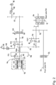
- FIG. 1 schematically illustrates an agricultural vehicle 10 in the form of a tractor, having front wheels 12 driven by a front axle 14, rear wheels 16 driven by a rear axle 18, a front hood 20 covering inter alia a storage battery 22 coupled via a power electronics (switching/charging) stage 24 to first and second electric motors M1, M2.
- the electric motors M1, M2 form part of a driveline (indicated generally by dashed line 26) providing motive power to the front and rear axles 14, 18 under control of an electronic control unit (ECU) 28.
- the driveline 26 also includes a power take-off shaft 30 which outputs a driven rotary drive to implements such as balers, tedders etc. coupled to the rear of the tractor.
- the tractor 10 includes a user station in the form of a cab 32 which may suitably comprise a user interface/control unit 34 by means of which a user may set or adjust operational parameters via the ECU 28.
- Figure 2 shows an exemplary first configuration of the driveline.
- the first M1 and second M2 electric drive motors are close coupled (connected to each other) with their respective output shafts 38, 40 being coaxial.
- an epicyclic (planetary) gear arrangement PG (which may optionally be enclosed within the single housing 42) with the first input shaft 38 directly (drivingly) coupled to the sun gear 44 thereof, and the second input shaft 40 directly coupled to one or more of the planetary gears 46 of the epicyclic PG.
- the outer ring gear 48 of the epicyclic PG is directly coupled to a first output shaft 40A and from there, via one or more connecting gears 50, drives an input shaft 52 of the drive to the front and rear axles 14, 18.
- the output shaft 52 is connected via a differential and braking unit 54 to the rear axle 18, and via a gearing linkage 56 and clutch unit 58 to the front axle 14.
- the second output shaft 38 (an extension of the first input shaft and suitably a unitary body therewith) is connected via a brake and clutch unit 60 to a reduction gearing 62 which in turn drives the PTO output shaft 30.
- the clutch portion C of the brake and clutch unit 60 is operable to connect/disconnect the PTO shaft 30 from the second output shaft 38.
- the brake portion B of the brake and clutch unit 60 is on the motor side (relative to the clutch portion C) and, when actuated, prevents rotation of the second output shaft 38 and first electric motor M1.
- the first electric motor M1 drives a main hydraulic pump PM 64 via the second output shaft 38 and a gearing linkage 68.
- the main pump 64 supplies pressurised fluid from a first fluid reservoir R1 to consumers on or attached to the vehicle e.g. lifting cylinders forming part of a front or rear linkage, a front loader, and/or a front suspension of the vehicle.
- the second electric motor M2 drives a steering hydraulic pump PST 66 via the input shaft 52 and a gearing linkage 70.
- the steering pump 66 supplies pressurised fluid from a second fluid reservoir R2 (which may be separate from or common with R1) to a hydraulic steering system of the vehicle/ tractor.
- the main pump PM 64 (supplying fluid to e.g. the lifting cylinders or the front suspension) is installed in the drive line connected to motor M1 but prior to the clutch/brake assembly 60 connecting the PTO 30 in this first embodiment. This has some major advantages:
- a first option is to connect a suitable electric power supply, via an external connector (80; Fig. 1 ) on the vehicle and the power electronics stage 24, to the battery or batteries 22.
- This conventional option is typically performed at some base location for the vehicle and suitably carried out overnight.
- the second output shaft 38 is driven by an external source to cause the or each of the electric motors M1, M2 to act as a generator and thereby supply a charging current to the or each of the storage batteries 22.
- an external source of hydraulic pressure P IN is coupled, via an external connector 82 on the vehicle, to drive the main hydraulic pump 64 as a hydraulic motor. Through gearing linkage 68 this drives the second output shaft 38. Note that in this situation, both the brake B and clutch C of the brake/clutch arrangement 60 should be disengaged to prevent driving of the PTO 30. Note also that if the second electric motor M2 is to be connected to the first M1 so that both are charging, a further clutch mechanism (not shown) should be provided to disengage the drive to the front and rear axles 14, 18.
- the fluid input from the connector 82 to the pump 64 may suitably include a flow limiter 84 controlled by the ECU (28; Fig. 1 ) to control the fluid flow and thereby the pump speed and generating motor speed by reference to a charging characteristic and/or charge level of the battery or batteries 22.
- FIG. 3 schematically illustrates the second option, with vehicle 10 being charged by a further an agricultural vehicle 110 (in the form of a tractor).
- the further vehicle 110 has front wheels 112 driven by a front axle 114, rear wheels 116 driven by a rear axle 118, and a front hood 120.
- a driveline (indicated generally by dashed line 126) provides motive power to the front and rear axles 114, 118 under control of an electronic control unit (ECU) 128.
- the driveline 126 also includes front and rear power take-off shafts 90, 130 which output a driven rotary drive to implements coupled to the vehicle 110.
- the vehicle 110 includes a user station in the form of a cab 132 which may suitably comprise a user interface/control unit 134 by means of which a user may set or adjust operational parameters via the ECU 128.
- an external source of rotational energy 86 is coupled to drive the PTO 30 and gearing linkage 62 of the vehicle 10.
- both the brake B of the brake/clutch arrangement 60 should be disengaged and the clutch C engaged to couple the PTO 30 to the second output shaft 38.
- the PTO shaft 30 is suitably provided with a connecting shaft (such as a cardan shaft) 88 to drivingly couple with one of the PTO shafts 90, 130 of the further vehicle 110 (providing the source of the rotational energy 86).
- the connecting shaft 88 suitably connects the rear-mounted PTO 30 of the vehicle 10 to be charged with the front-mounted PTO 90 of the further (charging) vehicle 110.
- the power electronic stage (24; Fig. 1 ) suitably acts as a current limiter to control a maximum recharge current by reference to one or more charging characteristics of the or each motor M1, M2 and/or charge level of the battery or batteries 22 when driven in this "reverse" (charging) mode.
- both vehicles 10, 110 in the arrangement of Fig. 3 have respective ECU's 28, 128, these ECU's are preferably connected during recharging (by ISOBUS link 92 or similar connection), with the ECU of the agricultural/utility vehicle 10 being charged controlling delivery by the appropriate power source, by controlling the PTO 90 of the further (charging) vehicle 110 via the ECU 128 of the further vehicle 110.
- Such an ISOBUS link 92 may also be used to control the delivery of hydraulic pressure from the further vehicle 110 to the first 10 where the power supply is in the form of the first option described above.
- an agricultural/utility vehicle 10 which has as its motive power source one or more electric motors M1, M2 supplied by one or more rechargeable batteries 22 to drivingly rotate a shaft 38 of the vehicle driveline.
- an external power source P IN , 86 is applied to cause the driveline shaft 38 to rotate, resulting in the, or one of the, electric motors M1 acting as a generator to recharge the batteries 22.
- the external power source may comprise a source of fluid pressure P IN driving a hydraulic pump 64 of the driveline as a hydraulic motor, or an external source of rotational energy 86 coupled to a power take-off shaft 30 of the vehicle.
Landscapes
- Engineering & Computer Science (AREA)
- Mechanical Engineering (AREA)
- Transportation (AREA)
- Chemical & Material Sciences (AREA)
- Combustion & Propulsion (AREA)
- Power Engineering (AREA)
- Sustainable Development (AREA)
- Sustainable Energy (AREA)
- Life Sciences & Earth Sciences (AREA)
- Physics & Mathematics (AREA)
- Fluid Mechanics (AREA)
- General Engineering & Computer Science (AREA)
- Electric Propulsion And Braking For Vehicles (AREA)
- Arrangement And Driving Of Transmission Devices (AREA)
- Hybrid Electric Vehicles (AREA)
Description
- The present invention relates to driveline/transmission systems for utility vehicles, particularly self-propelled agricultural machines such as farm tractors, and more particularly to such systems for electrically powered vehicles.
- It is known that conventional agricultural vehicles such as tractors powered by internal combustion engines are not ecologically efficient due to the high volumes of fossil fuels consumed during operation. Furthermore, despite the legal imposition of increasingly stringent exhaust gas emission standards, generated pollution from such vehicles continues to be a concern. With the expectation that future legislation will only be more stringent, cleaner (more fuel efficient/less polluting) solutions such as hybrid or fully electric vehicles are desired.
- United States patent
US 8,469,127 describes an example of a hybrid drive line for an agricultural or industrial utility vehicle, such as a tractor. The driveline includes a drive assembly which generates a mechanical torque by means of an internal combustion engine and first, second and third electrical motors. The drive assembly has a first mechanical output shaft, driven by the second electric motor, which serves to drive at least one vehicle axle, and a second mechanical output shaft in the form of a power take-off (PTO) shaft. The internal combustion engine and first electric motor are each coupled to drive the second mechanical output shaft (PTO). - In one configuration of the driveline of
US 8,469,127 , first and second electric motors are positioned adjacent one another (with driveshafts parallel and spaced apart) with the respective output driveshafts drivingly connected to one of the sun and planetary gears of an epicyclic gear arrangement, via one or more gear linkages for spatial reasons, with the outer epicylic ring gear driving the first output shaft and axle or axles of the vehicle, and the sun gear driving the second output shaft and the PTO. The third and, in some configurations, fourth electric motors are connected or connectable into the motive power portion of the driveline (to one or both of the front and rear axles) downstream of the drive to the PTO. - Whilst it is understood that such a hybrid arrangement is more ecologically efficient in terms of reduced pollution through reduced fossil fuel usage and hence reduced emissions, the above-described arrangement is wasteful and costly in terms of the number of components (up to four electric motors in addition to an internal combustion engine) and causes problems from simply trying to physically accommodate them all in the relatively constrained space available under a tractor hood. It is an aim of tractor manufacturers to keep the profile of the hood as low as possible to improve the users view of the area in front of the vehicle and to either side of the hood around the front wheels. Control issues also become a problem in an arrangement such as that of
US 8,469,127 with the need for coordination of the output speeds of the internal combustion engine and at least the first electric motor to ensure that the first electric motor is not being effectively driven in reverse (i.e. acting as a generator). - The per-vehicle fossil fuel usage and emissions issue is addressed at least partially by a fully electric vehicle, with pure electrical drives being more efficient (less energy wasting) than internal combustion engines. Some spatial concerns remain as the space currently filled by an internal combustion engine (and conventional gearbox or continuously variable transmission (CVT)) in a conventional vehicle is instead given over to storage batteries (as it is understandably a goal that a working farm tractor should not have to return to base for recharging part-way through a working day) and power electronics for control of the electric motors. The latter may be simplified or avoided in a so-called intermediate hybrid in which a fully electric power source, operating at one or a limited range of speeds, is coupled with a conventional CVT. Whilst it is expected that ongoing developments in battery technology will continue to reduce the physical volume required to accommodate rechargeable battery storage sufficient to supply increasing capabilities of a working vehicle for a full day's work without recharging, it is also the case that unplanned conditions (e.g. heavier than expected soil due to weather conditions) may cause storage batteries to discharge faster than planned. In such circumstances it is not desirable that the vehicle have to be towed back to the base for recharging.
- In accordance with the invention there is provided agricultural/utility vehicle having as its motive power source one or more electric motors supplied by one or more rechargeable batteries, which electric motor or motors are connected to drivingly rotate a shaft of a driveline when coupled to provide motive power to one or more axles of the vehicle, the vehicle having one or more recharging inputs which, when coupled to an appropriate power source, cause the driveline shaft to rotate, causing the, or one of the, electric motors to act as a generator to recharge the one or more rechargeable batteries.
- The driveline includes a hydraulic pump driven by rotation of the driveline shaft to supply pressurised fluid to one or more consumers on or attached to the vehicle, and the recharging input comprises an external source of hydraulic pressure operable to cause the hydraulic pump to act as a hydraulic motor rotatably driving the driveline shaft and thereby the, or one of the, electric motors. In such an arrangement, the vehicle suitably carries an external port providing the recharging input to receive hydraulic pressure to drive the hydraulic pump. A flow limiter may be provided to restrict the flow of pressurised hydraulic fluid by reference to one or more charging characteristics of the or each rechargeable battery, and a charge control mechanism may be provided configured to periodically adjust the flow of pressurised hydraulic fluid by the flow limiter in dependence on a current charge level of the or each rechargeable battery.
- In a preferred arrangement, where the vehicle driveline includes a power take-off (PTO) drive shaft driven by the, or one of the, electric motors via the driveline shaft to provide rotational drive to an implement connected with the vehicle, the appropriate power source comprises connection of the PTO shaft to an externally-driven source of rotation, which drives at least one of the electric motors via the driveline shaft to act as a generator. In such an arrangement, the PTO shaft is suitably further provided with a connecting shaft to drivingly couple with a PTO shaft of another agricultural/utility vehicle, and the or each electric motor is preferably provided with a current limiter to control a maximum recharge current by reference to one or more charging characteristics of the or each electric motor when driven in a reverse (charging) mode.
- The appropriate power source, whether electrical, mechanical or hydraulic, is preferably provided by a further vehicle. Where both vehicles have respective electronic control units (ECU), the ECU's are preferably connected during recharging (by ISOBUS or similar connection), with the ECU of the agricultural/utility vehicle being charged controlling delivery by the appropriate power source via the ECU of the further vehicle.
- In accordance with a further aspect of the present invention there is provided a method of recharging the storage battery or batteries of an agricultural/utility vehicle, which vehicle includes one or more electric motors driven by said storage battery or batteries and which electric motors rotationally drive a driveline shaft providing rotational drive to one or more motive power axles of the vehicle or one or more consumers coupled with the vehicle to receive a rotational drive therefrom, the method comprising coupling an external energy source to cause the driveline shaft and thereby the, or one of the, electric motors to operate as a generator.
- The vehicle comprises a hydraulic pump coupled to be driven by the driveline shaft, and the coupling of an external energy source suitably comprises coupling an external source of fluid pressure such as to cause the hydraulic pump to operate as a hydraulic motor, and thereby cause the, or one of the, electric motors to operate as a generator. Where the vehicle comprises a power take-off (PTO) shaft directly driven by one or more of the electric motors, the coupling of an external energy source suitably comprises coupling an external source of rotational energy to the PTO shaft such as to cause the, or one of the, electric motors to operate as a generator, and thereby deliver a charge to the or one of the batteries.
- Further advantages of the invention will become apparent from reading the following description of specific embodiments with reference to the appended drawings in which:-
-
Figure 1 is a representation of an agricultural/utility vehicle, in the form of a tractor, provided with a driveline according to one or more embodiments of the present invention; -
Figure 2 is a schematic view of an embodiment of driveline of the vehicle ofFig. 1 ; and -
Figure 3 shows the vehicle ofFig. 1 being charged by a further vehicle. -
Figure 1 schematically illustrates anagricultural vehicle 10 in the form of a tractor, havingfront wheels 12 driven by afront axle 14,rear wheels 16 driven by arear axle 18, afront hood 20 covering inter alia astorage battery 22 coupled via a power electronics (switching/charging)stage 24 to first and second electric motors M1, M2. The electric motors M1, M2 form part of a driveline (indicated generally by dashed line 26) providing motive power to the front andrear axles driveline 26 also includes a power take-off shaft 30 which outputs a driven rotary drive to implements such as balers, tedders etc. coupled to the rear of the tractor. Thetractor 10 includes a user station in the form of acab 32 which may suitably comprise a user interface/control unit 34 by means of which a user may set or adjust operational parameters via theECU 28. -
Figure 2 shows an exemplary first configuration of the driveline. The first M1 and second M2 electric drive motors are close coupled (connected to each other) with theirrespective output shafts line 42. - Mounted adjacent the motive power unit M1, M2 is an epicyclic (planetary) gear arrangement PG (which may optionally be enclosed within the single housing 42) with the
first input shaft 38 directly (drivingly) coupled to thesun gear 44 thereof, and thesecond input shaft 40 directly coupled to one or more of the planetary gears 46 of the epicyclic PG. Theouter ring gear 48 of the epicyclic PG is directly coupled to a first output shaft 40A and from there, via one or more connecting gears 50, drives aninput shaft 52 of the drive to the front andrear axles output shaft 52 is connected via a differential andbraking unit 54 to therear axle 18, and via agearing linkage 56 andclutch unit 58 to thefront axle 14. - The second output shaft 38 (an extension of the first input shaft and suitably a unitary body therewith) is connected via a brake and
clutch unit 60 to areduction gearing 62 which in turn drives thePTO output shaft 30. The clutch portion C of the brake andclutch unit 60 is operable to connect/disconnect thePTO shaft 30 from thesecond output shaft 38. The brake portion B of the brake andclutch unit 60 is on the motor side (relative to the clutch portion C) and, when actuated, prevents rotation of thesecond output shaft 38 and first electric motor M1. - The first electric motor M1 drives a main
hydraulic pump PM 64 via thesecond output shaft 38 and agearing linkage 68. Themain pump 64 supplies pressurised fluid from a first fluid reservoir R1 to consumers on or attached to the vehicle e.g. lifting cylinders forming part of a front or rear linkage, a front loader, and/or a front suspension of the vehicle. - The second electric motor M2 drives a steering hydraulic pump PST 66 via the
input shaft 52 and agearing linkage 70. The steering pump 66 supplies pressurised fluid from a second fluid reservoir R2 (which may be separate from or common with R1) to a hydraulic steering system of the vehicle/ tractor. - The main pump PM 64 (supplying fluid to e.g. the lifting cylinders or the front suspension) is installed in the drive line connected to motor M1 but prior to the clutch/
brake assembly 60 connecting thePTO 30 in this first embodiment. This has some major advantages: - 1. Only one pump (i.e. 66) is required to ensure steering and that pump is constantly driven;
- 2. Installing the
main pump 64 in the driveline connected with M1 enables thismain pump 64 to be switched off e.g. when driving on the road where there is minor hydraulic consumption compared to field work. In the case that increased steering power is requested (e.g. when turning), the motor M1 may be activated while thePTO 30 branch is disconnected by the clutch part C of the brake/clutch assembly 60. - 3. In the case where the tractor is operated with an implement, both the
main pump PM 64 and the PTO 30 may be operated. - In order to recharge the storage battery or
batteries 22, a first option is to connect a suitable electric power supply, via an external connector (80;Fig. 1 ) on the vehicle and thepower electronics stage 24, to the battery orbatteries 22. This conventional option is typically performed at some base location for the vehicle and suitably carried out overnight. - In order to recharge the storage battery or
batteries 22 in a field location, where a suitable source of electrical power may be unavailable, two options are provided. In both options, thesecond output shaft 38 is driven by an external source to cause the or each of the electric motors M1, M2 to act as a generator and thereby supply a charging current to the or each of thestorage batteries 22. - In the first option, an external source of hydraulic pressure PIN is coupled, via an
external connector 82 on the vehicle, to drive the mainhydraulic pump 64 as a hydraulic motor. Throughgearing linkage 68 this drives thesecond output shaft 38. Note that in this situation, both the brake B and clutch C of the brake/clutch arrangement 60 should be disengaged to prevent driving of thePTO 30. Note also that if the second electric motor M2 is to be connected to the first M1 so that both are charging, a further clutch mechanism (not shown) should be provided to disengage the drive to the front andrear axles - The fluid input from the
connector 82 to thepump 64 may suitably include a flow limiter 84 controlled by the ECU (28;Fig. 1 ) to control the fluid flow and thereby the pump speed and generating motor speed by reference to a charging characteristic and/or charge level of the battery orbatteries 22. -
Figure 3 schematically illustrates the second option, withvehicle 10 being charged by a further an agricultural vehicle 110 (in the form of a tractor). Thefurther vehicle 110 hasfront wheels 112 driven by afront axle 114,rear wheels 116 driven by arear axle 118, and afront hood 120. A driveline (indicated generally by dashed line 126) provides motive power to the front andrear axles driveline 126 also includes front and rear power take-offshafts vehicle 110. Thevehicle 110 includes a user station in the form of acab 132 which may suitably comprise a user interface/control unit 134 by means of which a user may set or adjust operational parameters via the ECU 128. - In the second option, an external source of
rotational energy 86 is coupled to drive thePTO 30 and gearinglinkage 62 of thevehicle 10. Note that in this situation, both the brake B of the brake/clutch arrangement 60 should be disengaged and the clutch C engaged to couple thePTO 30 to thesecond output shaft 38. ThePTO shaft 30 is suitably provided with a connecting shaft (such as a cardan shaft) 88 to drivingly couple with one of thePTO shafts Fig. 3 , the connectingshaft 88 suitably connects the rear-mountedPTO 30 of thevehicle 10 to be charged with the front-mountedPTO 90 of the further (charging)vehicle 110. - The power electronic stage (24;
Fig. 1 ) suitably acts as a current limiter to control a maximum recharge current by reference to one or more charging characteristics of the or each motor M1, M2 and/or charge level of the battery orbatteries 22 when driven in this "reverse" (charging) mode. - Where both
vehicles Fig. 3 have respective ECU's 28, 128, these ECU's are preferably connected during recharging (byISOBUS link 92 or similar connection), with the ECU of the agricultural/utility vehicle 10 being charged controlling delivery by the appropriate power source, by controlling thePTO 90 of the further (charging)vehicle 110 via the ECU 128 of thefurther vehicle 110. Such anISOBUS link 92 may also be used to control the delivery of hydraulic pressure from thefurther vehicle 110 to the first 10 where the power supply is in the form of the first option described above. - In the foregoing the applicants have described an agricultural/
utility vehicle 10 which has as its motive power source one or more electric motors M1, M2 supplied by one or morerechargeable batteries 22 to drivingly rotate ashaft 38 of the vehicle driveline. To recharge thebatteries 22, an external power source PIN, 86 is applied to cause thedriveline shaft 38 to rotate, resulting in the, or one of the, electric motors M1 acting as a generator to recharge thebatteries 22. The external power source may comprise a source of fluid pressure PIN driving ahydraulic pump 64 of the driveline as a hydraulic motor, or an external source ofrotational energy 86 coupled to a power take-offshaft 30 of the vehicle. - From reading of the present disclosure, other modifications within the scope of the invention as defined in the appended claims will be apparent to those skilled in the art. Such modifications may involve other features which are already known in the field of vehicle driveline and power transmission systems and component parts therefore and which may be used instead of or in addition to features described herein.
Claims (11)
- An agricultural/utility vehicle (10) having as its motive power source one or more electric motors (M1, M2) supplied by one or more rechargeable batteries (22), which electric motor or motors (M1, M2) are connected to drivingly rotate a shaft (38) of a drive line when coupled to provide motive power to one or more axles (14, 18) of the vehicle, wherein the vehicle having one or more recharging inputs (82, 30) which, when coupled to an appropriate power source (PIN, 86), cause the driveline shaft (38) to rotate, causing the, or one of the, electric motors (M1) to act as a generator to recharge the one or more rechargeable batteries (22)
characterized in that
the drive line includes a hydraulic pump (64) driven by rotation of the driveline shaft (38) supplying pressurised fluid to one or more consumers on or attached to the vehicle, the recharging input (82) comprising an external source of hydraulic pressure (PIN) operable to cause the hydraulic pump (64) to act as a hydraulic motor rotatably driving the driveline shaft (38) and thereby the, or one of the, electric motors (M1). - An agricultural/utility vehicle as claimed in claim 1, wherein the vehicle carries an external port (82) providing the recharging input to receive hydraulic pressure to drive the hydraulic pump (64).
- An agricultural/utility vehicle as claimed in claim 1 or claim 2, further comprising a flow limiter (84) restricting the flow of pressurised hydraulic fluid to the hydraulic pump (64) by reference to one or more charging characteristics of the or each rechargeable battery (M1).
- An agricultural/utility vehicle as claimed in claim 3, further comprising a charge control mechanism (28) configured to periodically adjust the flow of pressurised hydraulic fluid by the flow limiter (84) in dependence on a current charge level of the or each rechargeable battery (M1).
- An agricultural/utility vehicle as claimed in claim 1, wherein the vehicle driveline includes a power take-off (PTO) drive shaft (30) driven by the, or one of the, electric motors (M1, M2) via the driveline shaft (38) to provide rotational drive to an implement connected with the vehicle, the appropriate power source comprising connection of the PTO shaft (30) to an externally-driven source of rotation (86), which drives at least one of the electric motors (M1) via the driveline shaft (38) to act as a generator.
- An agricultural/utility vehicle as claimed in claim 5, wherein the PTO shaft (30) is further provided with a connecting shaft (88) to drivingly couple with a PTO shaft of another agricultural/utility vehicle.
- An agricultural/utility vehicle as claimed in claim 5 or claim 6, wherein the or each electric motor (M1, M2) is provided with a current limiter (24) to control a maximum recharge current by reference to one or more charging characteristics of the or each electric motor (M1) when driven in a reverse (charging) mode.
- A method of recharging the storage battery or batteries (22) of an agricultural/utility vehicle (10), which vehicle includes one or more electric motors (M1, M2) driven by said storage battery or batteries and which electric motors rotationally drive a driveline shaft (38) providing rotational drive to one or more motive power axles (14, 18) of the vehicle or one or more consumers coupled with the vehicle to receive a rotational drive therefrom, the method comprising:- coupling an external energy source (PIN, 86) to cause the driveline shaft (38) and thereby the, or one of the, electric motors (M1, M2) to operate as a generator and thereby charge the battery or batteries (22)characterized in that
the vehicle comprises a hydraulic pump (64) coupled to be driven by the driveline shaft (38), and the coupling of an external energy source comprises coupling an external source of fluid pressure (PIN), such as to cause the hydraulic pump to (64) operate as a hydraulic motor, and thereby cause the, or one of the, electric motors (M1) to operate as a generator. - A method as claimed in claim 8, wherein the appropriate power source is provided by a further vehicle (110).
- A method as claimed in claim 9, wherein the agricultural/utility vehicle (10) and further vehicle (110) each have respective electronic control units ECU (28, 128), with the ECU's (28, 128) being connected during recharging, and the ECU (28) of the agricultural/utility vehicle (10) controlling delivery by the appropriate power source via the ECU (128) of the further vehicle (110).
- A method as claimed in claim 9, wherein the ECUs of the agricultural/utility vehicle (10) and the further vehicle (110) are configured to communicate using ISOBUS and the method further comprises connecting the ECU's (28, 128) using an ISOBUS link.
Applications Claiming Priority (2)
| Application Number | Priority Date | Filing Date | Title |
|---|---|---|---|
| GBGB1816590.2A GB201816590D0 (en) | 2018-10-11 | 2018-10-11 | Electric utility vehicle driveline recharging |
| PCT/EP2019/076696 WO2020074342A1 (en) | 2018-10-11 | 2019-10-02 | Electric utility vehicle driveline recharging |
Publications (3)
| Publication Number | Publication Date |
|---|---|
| EP3863876A1 EP3863876A1 (en) | 2021-08-18 |
| EP3863876B1 EP3863876B1 (en) | 2022-08-10 |
| EP3863876B2 true EP3863876B2 (en) | 2025-04-23 |
Family
ID=64394815
Family Applications (1)
| Application Number | Title | Priority Date | Filing Date |
|---|---|---|---|
| EP19786733.6A Active EP3863876B2 (en) | 2018-10-11 | 2019-10-02 | Electric utility vehicle driveline recharging |
Country Status (4)
| Country | Link |
|---|---|
| US (1) | US11858365B2 (en) |
| EP (1) | EP3863876B2 (en) |
| GB (1) | GB201816590D0 (en) |
| WO (1) | WO2020074342A1 (en) |
Families Citing this family (12)
| Publication number | Priority date | Publication date | Assignee | Title |
|---|---|---|---|---|
| US11926209B2 (en) * | 2020-02-19 | 2024-03-12 | Deere & Company | Electric power take off |
| US11912151B2 (en) * | 2020-07-31 | 2024-02-27 | Robert Bosch Gmbh | Reconfigurable electric vehicle chassis |
| DE102021118661A1 (en) * | 2021-07-20 | 2023-01-26 | Audi Aktiengesellschaft | powertrain and motor vehicle |
| DE102021209593A1 (en) * | 2021-09-01 | 2023-03-02 | Zf Friedrichshafen Ag | Drive unit for an electric vehicle |
| US11991943B2 (en) * | 2022-02-03 | 2024-05-28 | Zimeno Inc. | Vehicle electric motor hydraulic pump decoupling |
| JP7796612B2 (en) * | 2022-08-30 | 2026-01-09 | 株式会社クボタ | Electric work vehicle and charging method |
| EP4279305A1 (en) * | 2022-10-19 | 2023-11-22 | Volvo Construction Equipment AB | A charging arrangement and a method for charging an electrically powered working machine |
| US12351009B2 (en) * | 2022-10-31 | 2025-07-08 | Dana Heavy Vehicle Systems Group, Llc | Systems and methods for an electric axle |
| GB202218507D0 (en) * | 2022-12-08 | 2023-01-25 | Agco Int Gmbh | Vehicle powertrain, method and vehicle |
| US20250135857A1 (en) * | 2023-10-30 | 2025-05-01 | Kubota Corporation | Electric work vehicle |
| IT202300023826A1 (en) * | 2023-11-10 | 2025-05-10 | Carraro Spa | TRANSMISSION GROUP FOR ELECTRIC VEHICLES |
| JP2025187951A (en) * | 2024-06-13 | 2025-12-25 | トラクターズ アンド ファーム イクイップメント リミテッド | Powertrain for agricultural tractor with dual drive and dual independent output electrical machine |
Citations (2)
| Publication number | Priority date | Publication date | Assignee | Title |
|---|---|---|---|---|
| US20090018716A1 (en) † | 2007-07-12 | 2009-01-15 | Joseph Mario Ambrosio | Parallel hybrid drive system utilizing power take off connection as transfer for a secondary energy source |
| US20110024255A1 (en) † | 2009-07-28 | 2011-02-03 | Gomm Ralf | Electrical interrupt system and method for use in a hybrid system |
Family Cites Families (18)
| Publication number | Priority date | Publication date | Assignee | Title |
|---|---|---|---|---|
| JPH07223589A (en) | 1994-02-07 | 1995-08-22 | Mitsubishi Heavy Ind Ltd | Electric charging system for submersible body |
| DE4425387C1 (en) | 1994-07-19 | 1996-04-11 | Schmetz Roland Dipl Wirtsch In | Agricultural tractor with electromechanical transmission |
| DE19623738C2 (en) * | 1996-06-14 | 1998-08-06 | Deere & Co | Electric vehicle |
| DE10052231A1 (en) * | 2000-10-21 | 2002-05-02 | Daimler Chrysler Ag | vehicle |
| US7128671B2 (en) * | 2001-12-20 | 2006-10-31 | Huan-Lung Gu | Hybrid power system with external auxiliary motor |
| DE102005044180A1 (en) * | 2005-09-15 | 2007-09-06 | Deere & Company, Moline | Drive system for an agricultural or industrial utility vehicle and method for operating a drive system |
| US20070107957A1 (en) * | 2005-11-16 | 2007-05-17 | Lonnie Lehrer | Automobile propulsion system |
| JP4052483B2 (en) * | 2006-05-30 | 2008-02-27 | 三菱重工業株式会社 | Work vehicle |
| US8978798B2 (en) * | 2007-10-12 | 2015-03-17 | Odyne Systems, Llc | Hybrid vehicle drive system and method and idle reduction system and method |
| US7828091B2 (en) * | 2007-12-12 | 2010-11-09 | Wedderburn Jr Cosburn Henry | Air electric vehicle |
| US7828099B2 (en) * | 2008-02-25 | 2010-11-09 | Stephen Heckeroth | Electric tractor |
| US20100117594A1 (en) * | 2008-11-13 | 2010-05-13 | International Truck Intellectual Property Company, Llc | Strategy for maintaining state of charge of a low-voltage battery bank in a hybrid electric vehicle having a high-voltage traction battery bank |
| US20110031051A1 (en) * | 2009-07-17 | 2011-02-10 | Albert Donald George | Rechargeable electric vehicle with extended driving range, and method of converting vehicle with internal combustion (IC) engine to rechargeable electric vehicle |
| GB0915402D0 (en) * | 2009-09-04 | 2009-10-07 | Agco Gmbh | Tractors |
| KR101302262B1 (en) * | 2011-03-30 | 2013-09-02 | 가부시끼 가이샤 구보다 | Working car |
| US20120262018A1 (en) * | 2011-04-18 | 2012-10-18 | Hardial Singh Thiara | Self generating electrical system |
| US8984973B1 (en) * | 2013-11-07 | 2015-03-24 | Agco International Gmbh | Multiple speed power take off |
| GB2521626C (en) | 2013-12-23 | 2019-10-30 | Subsea 7 Ltd | Transmission of power underwater |
-
2018
- 2018-10-11 GB GBGB1816590.2A patent/GB201816590D0/en not_active Ceased
-
2019
- 2019-10-02 WO PCT/EP2019/076696 patent/WO2020074342A1/en not_active Ceased
- 2019-10-02 US US17/284,593 patent/US11858365B2/en active Active
- 2019-10-02 EP EP19786733.6A patent/EP3863876B2/en active Active
Patent Citations (2)
| Publication number | Priority date | Publication date | Assignee | Title |
|---|---|---|---|---|
| US20090018716A1 (en) † | 2007-07-12 | 2009-01-15 | Joseph Mario Ambrosio | Parallel hybrid drive system utilizing power take off connection as transfer for a secondary energy source |
| US20110024255A1 (en) † | 2009-07-28 | 2011-02-03 | Gomm Ralf | Electrical interrupt system and method for use in a hybrid system |
Non-Patent Citations (1)
| Title |
|---|
| MARISA KOCKOT, VOLKER KEGEL, VANESSA TRÖSTER, CLAUDIA SCHRANK: "SESAM - Entwicklung eines vollelektrifizierten Traktors - Teilvorhaben: Umsetzung eines vollelektrifizierten Traktors - kabelgeführt und batteriebetrieben", ABSCHLUSSBERICHT ZUM VERBUNDVORHABEN; FÖRDERKENNZEICHEN 01ME12122A; PROJEKTLAUFZEIT 01.01.2013-31.12.2015, 28 June 2016 (2016-06-28), XP093159158 † |
Also Published As
| Publication number | Publication date |
|---|---|
| EP3863876B1 (en) | 2022-08-10 |
| US20210252987A1 (en) | 2021-08-19 |
| GB201816590D0 (en) | 2018-11-28 |
| EP3863876A1 (en) | 2021-08-18 |
| US11858365B2 (en) | 2024-01-02 |
| WO2020074342A1 (en) | 2020-04-16 |
Similar Documents
| Publication | Publication Date | Title |
|---|---|---|
| EP3863876B2 (en) | Electric utility vehicle driveline recharging | |
| EP3863877B1 (en) | Utility vehicle driveline | |
| US8347998B2 (en) | Working machine with one or more electric machines for driving, braking, and/or generating power and a method for operating such a working machine | |
| EP3498516B1 (en) | Articulated tracked vehicle | |
| US11845337B2 (en) | Electric hybrid transmission architecture for a work vehicle | |
| CN102427978B (en) | Construction machinery and equipment and the method for operating construction machinery and equipment | |
| US7424924B2 (en) | Hybrid electric vehicle powertrain with torque transfer case | |
| WO2011138308A1 (en) | Tractor with hybrid power system | |
| US8157034B2 (en) | Vehicle assembly with independent electric wheel motors for electric hybrid vehicles | |
| GB2493961A (en) | Power takeoff drive system for an agricultural tractor | |
| SE543431C2 (en) | A powertrain for a vehicle | |
| CN120156284A (en) | Electrohydraulic hybrid drive for a motor vehicle | |
| US20220134860A1 (en) | Hybrid agricultural vehicle | |
| EP3946997B1 (en) | Hybrid transmission unit for a tractor and tractor comprising the same | |
| CN110242409B (en) | Series connection dual-motor global automatic gear shifting transmission system | |
| EP4488094A1 (en) | Agricultural machine with improved mounting volume | |
| JP7803390B2 (en) | Paddy field farming machine | |
| CN223890790U (en) | Agricultural machinery driving system and agricultural machinery | |
| US20260091668A1 (en) | Independent power split transfer drivetrain for electric vehicles and a method thereof | |
| GB2454888A (en) | Hybrid vehicle motor control matched to generation capability | |
| WO2021110243A1 (en) | A hybrid powertrain system for a vehicle | |
| CN224130872U (en) | CVT power assembly of efficient tractor | |
| WO2024121635A1 (en) | Vehicle powertrain, method and vehicle | |
| CN117621797A (en) | Dual-motor independently controlled heavy tractor hybrid power system |
Legal Events
| Date | Code | Title | Description |
|---|---|---|---|
| STAA | Information on the status of an ep patent application or granted ep patent |
Free format text: STATUS: UNKNOWN |
|
| STAA | Information on the status of an ep patent application or granted ep patent |
Free format text: STATUS: THE INTERNATIONAL PUBLICATION HAS BEEN MADE |
|
| PUAI | Public reference made under article 153(3) epc to a published international application that has entered the european phase |
Free format text: ORIGINAL CODE: 0009012 |
|
| STAA | Information on the status of an ep patent application or granted ep patent |
Free format text: STATUS: REQUEST FOR EXAMINATION WAS MADE |
|
| 17P | Request for examination filed |
Effective date: 20210511 |
|
| AK | Designated contracting states |
Kind code of ref document: A1 Designated state(s): AL AT BE BG CH CY CZ DE DK EE ES FI FR GB GR HR HU IE IS IT LI LT LU LV MC MK MT NL NO PL PT RO RS SE SI SK SM TR |
|
| DAV | Request for validation of the european patent (deleted) | ||
| DAX | Request for extension of the european patent (deleted) | ||
| GRAP | Despatch of communication of intention to grant a patent |
Free format text: ORIGINAL CODE: EPIDOSNIGR1 |
|
| STAA | Information on the status of an ep patent application or granted ep patent |
Free format text: STATUS: GRANT OF PATENT IS INTENDED |
|
| INTG | Intention to grant announced |
Effective date: 20220520 |
|
| GRAS | Grant fee paid |
Free format text: ORIGINAL CODE: EPIDOSNIGR3 |
|
| GRAA | (expected) grant |
Free format text: ORIGINAL CODE: 0009210 |
|
| STAA | Information on the status of an ep patent application or granted ep patent |
Free format text: STATUS: THE PATENT HAS BEEN GRANTED |
|
| AK | Designated contracting states |
Kind code of ref document: B1 Designated state(s): AL AT BE BG CH CY CZ DE DK EE ES FI FR GB GR HR HU IE IS IT LI LT LU LV MC MK MT NL NO PL PT RO RS SE SI SK SM TR |
|
| REG | Reference to a national code |
Ref country code: AT Ref legal event code: REF Ref document number: 1510262 Country of ref document: AT Kind code of ref document: T Effective date: 20220815 Ref country code: CH Ref legal event code: EP |
|
| REG | Reference to a national code |
Ref country code: IE Ref legal event code: FG4D |
|
| REG | Reference to a national code |
Ref country code: DE Ref legal event code: R096 Ref document number: 602019018197 Country of ref document: DE |
|
| REG | Reference to a national code |
Ref country code: NL Ref legal event code: MP Effective date: 20220810 |
|
| REG | Reference to a national code |
Ref country code: LT Ref legal event code: MG9D |
|
| PG25 | Lapsed in a contracting state [announced via postgrant information from national office to epo] |
Ref country code: SE Free format text: LAPSE BECAUSE OF FAILURE TO SUBMIT A TRANSLATION OF THE DESCRIPTION OR TO PAY THE FEE WITHIN THE PRESCRIBED TIME-LIMIT Effective date: 20220810 Ref country code: RS Free format text: LAPSE BECAUSE OF FAILURE TO SUBMIT A TRANSLATION OF THE DESCRIPTION OR TO PAY THE FEE WITHIN THE PRESCRIBED TIME-LIMIT Effective date: 20220810 Ref country code: PT Free format text: LAPSE BECAUSE OF FAILURE TO SUBMIT A TRANSLATION OF THE DESCRIPTION OR TO PAY THE FEE WITHIN THE PRESCRIBED TIME-LIMIT Effective date: 20221212 Ref country code: NO Free format text: LAPSE BECAUSE OF FAILURE TO SUBMIT A TRANSLATION OF THE DESCRIPTION OR TO PAY THE FEE WITHIN THE PRESCRIBED TIME-LIMIT Effective date: 20221110 Ref country code: NL Free format text: LAPSE BECAUSE OF FAILURE TO SUBMIT A TRANSLATION OF THE DESCRIPTION OR TO PAY THE FEE WITHIN THE PRESCRIBED TIME-LIMIT Effective date: 20220810 Ref country code: LV Free format text: LAPSE BECAUSE OF FAILURE TO SUBMIT A TRANSLATION OF THE DESCRIPTION OR TO PAY THE FEE WITHIN THE PRESCRIBED TIME-LIMIT Effective date: 20220810 Ref country code: LT Free format text: LAPSE BECAUSE OF FAILURE TO SUBMIT A TRANSLATION OF THE DESCRIPTION OR TO PAY THE FEE WITHIN THE PRESCRIBED TIME-LIMIT Effective date: 20220810 Ref country code: FI Free format text: LAPSE BECAUSE OF FAILURE TO SUBMIT A TRANSLATION OF THE DESCRIPTION OR TO PAY THE FEE WITHIN THE PRESCRIBED TIME-LIMIT Effective date: 20220810 |
|
| REG | Reference to a national code |
Ref country code: AT Ref legal event code: MK05 Ref document number: 1510262 Country of ref document: AT Kind code of ref document: T Effective date: 20220810 |
|
| PG25 | Lapsed in a contracting state [announced via postgrant information from national office to epo] |
Ref country code: PL Free format text: LAPSE BECAUSE OF FAILURE TO SUBMIT A TRANSLATION OF THE DESCRIPTION OR TO PAY THE FEE WITHIN THE PRESCRIBED TIME-LIMIT Effective date: 20220810 Ref country code: IS Free format text: LAPSE BECAUSE OF FAILURE TO SUBMIT A TRANSLATION OF THE DESCRIPTION OR TO PAY THE FEE WITHIN THE PRESCRIBED TIME-LIMIT Effective date: 20221210 Ref country code: HR Free format text: LAPSE BECAUSE OF FAILURE TO SUBMIT A TRANSLATION OF THE DESCRIPTION OR TO PAY THE FEE WITHIN THE PRESCRIBED TIME-LIMIT Effective date: 20220810 Ref country code: GR Free format text: LAPSE BECAUSE OF FAILURE TO SUBMIT A TRANSLATION OF THE DESCRIPTION OR TO PAY THE FEE WITHIN THE PRESCRIBED TIME-LIMIT Effective date: 20221111 |
|
| PG25 | Lapsed in a contracting state [announced via postgrant information from national office to epo] |
Ref country code: SM Free format text: LAPSE BECAUSE OF FAILURE TO SUBMIT A TRANSLATION OF THE DESCRIPTION OR TO PAY THE FEE WITHIN THE PRESCRIBED TIME-LIMIT Effective date: 20220810 Ref country code: RO Free format text: LAPSE BECAUSE OF FAILURE TO SUBMIT A TRANSLATION OF THE DESCRIPTION OR TO PAY THE FEE WITHIN THE PRESCRIBED TIME-LIMIT Effective date: 20220810 Ref country code: ES Free format text: LAPSE BECAUSE OF FAILURE TO SUBMIT A TRANSLATION OF THE DESCRIPTION OR TO PAY THE FEE WITHIN THE PRESCRIBED TIME-LIMIT Effective date: 20220810 Ref country code: DK Free format text: LAPSE BECAUSE OF FAILURE TO SUBMIT A TRANSLATION OF THE DESCRIPTION OR TO PAY THE FEE WITHIN THE PRESCRIBED TIME-LIMIT Effective date: 20220810 Ref country code: CZ Free format text: LAPSE BECAUSE OF FAILURE TO SUBMIT A TRANSLATION OF THE DESCRIPTION OR TO PAY THE FEE WITHIN THE PRESCRIBED TIME-LIMIT Effective date: 20220810 Ref country code: AT Free format text: LAPSE BECAUSE OF FAILURE TO SUBMIT A TRANSLATION OF THE DESCRIPTION OR TO PAY THE FEE WITHIN THE PRESCRIBED TIME-LIMIT Effective date: 20220810 |
|
| REG | Reference to a national code |
Ref country code: DE Ref legal event code: R026 Ref document number: 602019018197 Country of ref document: DE |
|
| PLBI | Opposition filed |
Free format text: ORIGINAL CODE: 0009260 |
|
| PLAX | Notice of opposition and request to file observation + time limit sent |
Free format text: ORIGINAL CODE: EPIDOSNOBS2 |
|
| PG25 | Lapsed in a contracting state [announced via postgrant information from national office to epo] |
Ref country code: SK Free format text: LAPSE BECAUSE OF FAILURE TO SUBMIT A TRANSLATION OF THE DESCRIPTION OR TO PAY THE FEE WITHIN THE PRESCRIBED TIME-LIMIT Effective date: 20220810 Ref country code: MC Free format text: LAPSE BECAUSE OF FAILURE TO SUBMIT A TRANSLATION OF THE DESCRIPTION OR TO PAY THE FEE WITHIN THE PRESCRIBED TIME-LIMIT Effective date: 20220810 Ref country code: EE Free format text: LAPSE BECAUSE OF FAILURE TO SUBMIT A TRANSLATION OF THE DESCRIPTION OR TO PAY THE FEE WITHIN THE PRESCRIBED TIME-LIMIT Effective date: 20220810 |
|
| REG | Reference to a national code |
Ref country code: CH Ref legal event code: PL |
|
| 26 | Opposition filed |
Opponent name: DEERE & COMPANY/JOHN DEERE GMBH & CO. KG Effective date: 20230510 |
|
| P01 | Opt-out of the competence of the unified patent court (upc) registered |
Effective date: 20230518 |
|
| REG | Reference to a national code |
Ref country code: BE Ref legal event code: MM Effective date: 20221031 |
|
| PG25 | Lapsed in a contracting state [announced via postgrant information from national office to epo] |
Ref country code: LU Free format text: LAPSE BECAUSE OF NON-PAYMENT OF DUE FEES Effective date: 20221002 Ref country code: AL Free format text: LAPSE BECAUSE OF FAILURE TO SUBMIT A TRANSLATION OF THE DESCRIPTION OR TO PAY THE FEE WITHIN THE PRESCRIBED TIME-LIMIT Effective date: 20220810 |
|
| PG25 | Lapsed in a contracting state [announced via postgrant information from national office to epo] |
Ref country code: LI Free format text: LAPSE BECAUSE OF NON-PAYMENT OF DUE FEES Effective date: 20221031 Ref country code: CH Free format text: LAPSE BECAUSE OF NON-PAYMENT OF DUE FEES Effective date: 20221031 |
|
| PG25 | Lapsed in a contracting state [announced via postgrant information from national office to epo] |
Ref country code: SI Free format text: LAPSE BECAUSE OF FAILURE TO SUBMIT A TRANSLATION OF THE DESCRIPTION OR TO PAY THE FEE WITHIN THE PRESCRIBED TIME-LIMIT Effective date: 20220810 |
|
| PLBB | Reply of patent proprietor to notice(s) of opposition received |
Free format text: ORIGINAL CODE: EPIDOSNOBS3 |
|
| PG25 | Lapsed in a contracting state [announced via postgrant information from national office to epo] |
Ref country code: BE Free format text: LAPSE BECAUSE OF NON-PAYMENT OF DUE FEES Effective date: 20221031 |
|
| PG25 | Lapsed in a contracting state [announced via postgrant information from national office to epo] |
Ref country code: IE Free format text: LAPSE BECAUSE OF NON-PAYMENT OF DUE FEES Effective date: 20221002 |
|
| PG25 | Lapsed in a contracting state [announced via postgrant information from national office to epo] |
Ref country code: CY Free format text: LAPSE BECAUSE OF FAILURE TO SUBMIT A TRANSLATION OF THE DESCRIPTION OR TO PAY THE FEE WITHIN THE PRESCRIBED TIME-LIMIT Effective date: 20220810 |
|
| PG25 | Lapsed in a contracting state [announced via postgrant information from national office to epo] |
Ref country code: MK Free format text: LAPSE BECAUSE OF FAILURE TO SUBMIT A TRANSLATION OF THE DESCRIPTION OR TO PAY THE FEE WITHIN THE PRESCRIBED TIME-LIMIT Effective date: 20220810 Ref country code: HU Free format text: LAPSE BECAUSE OF FAILURE TO SUBMIT A TRANSLATION OF THE DESCRIPTION OR TO PAY THE FEE WITHIN THE PRESCRIBED TIME-LIMIT; INVALID AB INITIO Effective date: 20191002 |
|
| GBPC | Gb: european patent ceased through non-payment of renewal fee |
Effective date: 20231002 |
|
| PG25 | Lapsed in a contracting state [announced via postgrant information from national office to epo] |
Ref country code: TR Free format text: LAPSE BECAUSE OF FAILURE TO SUBMIT A TRANSLATION OF THE DESCRIPTION OR TO PAY THE FEE WITHIN THE PRESCRIBED TIME-LIMIT Effective date: 20220810 |
|
| PG25 | Lapsed in a contracting state [announced via postgrant information from national office to epo] |
Ref country code: GB Free format text: LAPSE BECAUSE OF NON-PAYMENT OF DUE FEES Effective date: 20231002 |
|
| PG25 | Lapsed in a contracting state [announced via postgrant information from national office to epo] |
Ref country code: GB Free format text: LAPSE BECAUSE OF NON-PAYMENT OF DUE FEES Effective date: 20231002 Ref country code: BG Free format text: LAPSE BECAUSE OF FAILURE TO SUBMIT A TRANSLATION OF THE DESCRIPTION OR TO PAY THE FEE WITHIN THE PRESCRIBED TIME-LIMIT Effective date: 20220810 |
|
| PG25 | Lapsed in a contracting state [announced via postgrant information from national office to epo] |
Ref country code: MT Free format text: LAPSE BECAUSE OF FAILURE TO SUBMIT A TRANSLATION OF THE DESCRIPTION OR TO PAY THE FEE WITHIN THE PRESCRIBED TIME-LIMIT Effective date: 20220810 |
|
| APAH | Appeal reference modified |
Free format text: ORIGINAL CODE: EPIDOSCREFNO |
|
| APBP | Date of receipt of notice of appeal recorded |
Free format text: ORIGINAL CODE: EPIDOSNNOA2O |
|
| APBU | Appeal procedure closed |
Free format text: ORIGINAL CODE: EPIDOSNNOA9O |
|
| PUAH | Patent maintained in amended form |
Free format text: ORIGINAL CODE: 0009272 |
|
| STAA | Information on the status of an ep patent application or granted ep patent |
Free format text: STATUS: PATENT MAINTAINED AS AMENDED |
|
| 27A | Patent maintained in amended form |
Effective date: 20250423 |
|
| AK | Designated contracting states |
Kind code of ref document: B2 Designated state(s): AL AT BE BG CH CY CZ DE DK EE ES FI FR GB GR HR HU IE IS IT LI LT LU LV MC MK MT NL NO PL PT RO RS SE SI SK SM TR |
|
| REG | Reference to a national code |
Ref country code: DE Ref legal event code: R102 Ref document number: 602019018197 Country of ref document: DE |
|
| PGFP | Annual fee paid to national office [announced via postgrant information from national office to epo] |
Ref country code: DE Payment date: 20251021 Year of fee payment: 7 |
|
| PGFP | Annual fee paid to national office [announced via postgrant information from national office to epo] |
Ref country code: IT Payment date: 20251021 Year of fee payment: 7 |
|
| PGFP | Annual fee paid to national office [announced via postgrant information from national office to epo] |
Ref country code: FR Payment date: 20251030 Year of fee payment: 7 |