EP3863150A1 - Misalignment detection device and coil device - Google Patents
Misalignment detection device and coil device Download PDFInfo
- Publication number
- EP3863150A1 EP3863150A1 EP19868509.1A EP19868509A EP3863150A1 EP 3863150 A1 EP3863150 A1 EP 3863150A1 EP 19868509 A EP19868509 A EP 19868509A EP 3863150 A1 EP3863150 A1 EP 3863150A1
- Authority
- EP
- European Patent Office
- Prior art keywords
- coil
- temperature
- axis
- induction heating
- misalignment
- Prior art date
- Legal status (The legal status is an assumption and is not a legal conclusion. Google has not performed a legal analysis and makes no representation as to the accuracy of the status listed.)
- Pending
Links
Images



Classifications
-
- B—PERFORMING OPERATIONS; TRANSPORTING
- B60—VEHICLES IN GENERAL
- B60L—PROPULSION OF ELECTRICALLY-PROPELLED VEHICLES; SUPPLYING ELECTRIC POWER FOR AUXILIARY EQUIPMENT OF ELECTRICALLY-PROPELLED VEHICLES; ELECTRODYNAMIC BRAKE SYSTEMS FOR VEHICLES IN GENERAL; MAGNETIC SUSPENSION OR LEVITATION FOR VEHICLES; MONITORING OPERATING VARIABLES OF ELECTRICALLY-PROPELLED VEHICLES; ELECTRIC SAFETY DEVICES FOR ELECTRICALLY-PROPELLED VEHICLES
- B60L53/00—Methods of charging batteries, specially adapted for electric vehicles; Charging stations or on-board charging equipment therefor; Exchange of energy storage elements in electric vehicles
- B60L53/30—Constructional details of charging stations
- B60L53/35—Means for automatic or assisted adjustment of the relative position of charging devices and vehicles
- B60L53/37—Means for automatic or assisted adjustment of the relative position of charging devices and vehicles using optical position determination, e.g. using cameras
-
- H—ELECTRICITY
- H01—ELECTRIC ELEMENTS
- H01F—MAGNETS; INDUCTANCES; TRANSFORMERS; SELECTION OF MATERIALS FOR THEIR MAGNETIC PROPERTIES
- H01F27/00—Details of transformers or inductances, in general
- H01F27/40—Structural association with built-in electric component, e.g. fuse
- H01F27/402—Association of measuring or protective means
-
- B—PERFORMING OPERATIONS; TRANSPORTING
- B60—VEHICLES IN GENERAL
- B60L—PROPULSION OF ELECTRICALLY-PROPELLED VEHICLES; SUPPLYING ELECTRIC POWER FOR AUXILIARY EQUIPMENT OF ELECTRICALLY-PROPELLED VEHICLES; ELECTRODYNAMIC BRAKE SYSTEMS FOR VEHICLES IN GENERAL; MAGNETIC SUSPENSION OR LEVITATION FOR VEHICLES; MONITORING OPERATING VARIABLES OF ELECTRICALLY-PROPELLED VEHICLES; ELECTRIC SAFETY DEVICES FOR ELECTRICALLY-PROPELLED VEHICLES
- B60L53/00—Methods of charging batteries, specially adapted for electric vehicles; Charging stations or on-board charging equipment therefor; Exchange of energy storage elements in electric vehicles
- B60L53/10—Methods of charging batteries, specially adapted for electric vehicles; Charging stations or on-board charging equipment therefor; Exchange of energy storage elements in electric vehicles characterised by the energy transfer between the charging station and the vehicle
- B60L53/12—Inductive energy transfer
-
- B—PERFORMING OPERATIONS; TRANSPORTING
- B60—VEHICLES IN GENERAL
- B60L—PROPULSION OF ELECTRICALLY-PROPELLED VEHICLES; SUPPLYING ELECTRIC POWER FOR AUXILIARY EQUIPMENT OF ELECTRICALLY-PROPELLED VEHICLES; ELECTRODYNAMIC BRAKE SYSTEMS FOR VEHICLES IN GENERAL; MAGNETIC SUSPENSION OR LEVITATION FOR VEHICLES; MONITORING OPERATING VARIABLES OF ELECTRICALLY-PROPELLED VEHICLES; ELECTRIC SAFETY DEVICES FOR ELECTRICALLY-PROPELLED VEHICLES
- B60L53/00—Methods of charging batteries, specially adapted for electric vehicles; Charging stations or on-board charging equipment therefor; Exchange of energy storage elements in electric vehicles
- B60L53/30—Constructional details of charging stations
- B60L53/35—Means for automatic or assisted adjustment of the relative position of charging devices and vehicles
- B60L53/38—Means for automatic or assisted adjustment of the relative position of charging devices and vehicles specially adapted for charging by inductive energy transfer
-
- B—PERFORMING OPERATIONS; TRANSPORTING
- B60—VEHICLES IN GENERAL
- B60M—POWER SUPPLY LINES, AND DEVICES ALONG RAILS, FOR ELECTRICALLY- PROPELLED VEHICLES
- B60M7/00—Power lines or rails specially adapted for electrically-propelled vehicles of special types, e.g. suspension tramway, ropeway, underground railway
- B60M7/003—Power lines or rails specially adapted for electrically-propelled vehicles of special types, e.g. suspension tramway, ropeway, underground railway for vehicles using stored power (e.g. charging stations)
-
- G—PHYSICS
- G01—MEASURING; TESTING
- G01B—MEASURING LENGTH, THICKNESS OR SIMILAR LINEAR DIMENSIONS; MEASURING ANGLES; MEASURING AREAS; MEASURING IRREGULARITIES OF SURFACES OR CONTOURS
- G01B21/00—Measuring arrangements or details thereof, where the measuring technique is not covered by the other groups of this subclass, unspecified or not relevant
- G01B21/22—Measuring arrangements or details thereof, where the measuring technique is not covered by the other groups of this subclass, unspecified or not relevant for measuring angles or tapers; for testing the alignment of axes
- G01B21/24—Measuring arrangements or details thereof, where the measuring technique is not covered by the other groups of this subclass, unspecified or not relevant for measuring angles or tapers; for testing the alignment of axes for testing alignment of axes
-
- H—ELECTRICITY
- H01—ELECTRIC ELEMENTS
- H01F—MAGNETS; INDUCTANCES; TRANSFORMERS; SELECTION OF MATERIALS FOR THEIR MAGNETIC PROPERTIES
- H01F38/00—Adaptations of transformers or inductances for specific applications or functions
- H01F38/14—Inductive couplings
-
- H—ELECTRICITY
- H01—ELECTRIC ELEMENTS
- H01F—MAGNETS; INDUCTANCES; TRANSFORMERS; SELECTION OF MATERIALS FOR THEIR MAGNETIC PROPERTIES
- H01F7/00—Magnets
- H01F7/06—Electromagnets; Actuators including electromagnets
- H01F7/08—Electromagnets; Actuators including electromagnets with armatures
- H01F7/126—Supporting or mounting
-
- H—ELECTRICITY
- H01—ELECTRIC ELEMENTS
- H01F—MAGNETS; INDUCTANCES; TRANSFORMERS; SELECTION OF MATERIALS FOR THEIR MAGNETIC PROPERTIES
- H01F7/00—Magnets
- H01F7/06—Electromagnets; Actuators including electromagnets
- H01F7/08—Electromagnets; Actuators including electromagnets with armatures
- H01F7/127—Assembling
-
- H—ELECTRICITY
- H02—GENERATION; CONVERSION OR DISTRIBUTION OF ELECTRIC POWER
- H02J—ELECTRIC POWER NETWORKS; CIRCUIT ARRANGEMENTS OR SYSTEMS FOR SUPPLYING OR DISTRIBUTING ELECTRIC POWER; SYSTEMS FOR STORING ELECTRIC ENERGY
- H02J50/00—Circuit arrangements or systems for wireless supply or distribution of electric power
- H02J50/005—Mechanical details of housing or structure aiming to accommodate the power transfer means, e.g. mechanical integration of coils, antennas or transducers into emitting or receiving devices
-
- H—ELECTRICITY
- H02—GENERATION; CONVERSION OR DISTRIBUTION OF ELECTRIC POWER
- H02J—ELECTRIC POWER NETWORKS; CIRCUIT ARRANGEMENTS OR SYSTEMS FOR SUPPLYING OR DISTRIBUTING ELECTRIC POWER; SYSTEMS FOR STORING ELECTRIC ENERGY
- H02J50/00—Circuit arrangements or systems for wireless supply or distribution of electric power
- H02J50/10—Circuit arrangements or systems for wireless supply or distribution of electric power using inductive coupling
-
- H—ELECTRICITY
- H02—GENERATION; CONVERSION OR DISTRIBUTION OF ELECTRIC POWER
- H02J—ELECTRIC POWER NETWORKS; CIRCUIT ARRANGEMENTS OR SYSTEMS FOR SUPPLYING OR DISTRIBUTING ELECTRIC POWER; SYSTEMS FOR STORING ELECTRIC ENERGY
- H02J50/00—Circuit arrangements or systems for wireless supply or distribution of electric power
- H02J50/90—Circuit arrangements or systems for wireless supply or distribution of electric power involving detection or optimisation of position, e.g. alignment
-
- H—ELECTRICITY
- H01—ELECTRIC ELEMENTS
- H01F—MAGNETS; INDUCTANCES; TRANSFORMERS; SELECTION OF MATERIALS FOR THEIR MAGNETIC PROPERTIES
- H01F7/00—Magnets
- H01F7/06—Electromagnets; Actuators including electromagnets
- H01F2007/062—Details of terminals or connectors for electromagnets
-
- H—ELECTRICITY
- H01—ELECTRIC ELEMENTS
- H01F—MAGNETS; INDUCTANCES; TRANSFORMERS; SELECTION OF MATERIALS FOR THEIR MAGNETIC PROPERTIES
- H01F27/00—Details of transformers or inductances, in general
- H01F27/40—Structural association with built-in electric component, e.g. fuse
- H01F27/402—Association of measuring or protective means
- H01F2027/406—Temperature sensor or protection
-
- H—ELECTRICITY
- H01—ELECTRIC ELEMENTS
- H01F—MAGNETS; INDUCTANCES; TRANSFORMERS; SELECTION OF MATERIALS FOR THEIR MAGNETIC PROPERTIES
- H01F27/00—Details of transformers or inductances, in general
- H01F27/34—Special means for preventing or reducing unwanted electric or magnetic effects, e.g. no-load losses, reactive currents, harmonics, oscillations, leakage fields
- H01F27/38—Auxiliary core members; Auxiliary coils or windings
-
- H—ELECTRICITY
- H02—GENERATION; CONVERSION OR DISTRIBUTION OF ELECTRIC POWER
- H02J—ELECTRIC POWER NETWORKS; CIRCUIT ARRANGEMENTS OR SYSTEMS FOR SUPPLYING OR DISTRIBUTING ELECTRIC POWER; SYSTEMS FOR STORING ELECTRIC ENERGY
- H02J7/00—Circuit arrangements for charging or discharging batteries or for supplying loads from batteries
- H02J7/02—Circuit arrangements for charging or discharging batteries or for supplying loads from batteries for charging batteries from AC mains by converters
-
- Y—GENERAL TAGGING OF NEW TECHNOLOGICAL DEVELOPMENTS; GENERAL TAGGING OF CROSS-SECTIONAL TECHNOLOGIES SPANNING OVER SEVERAL SECTIONS OF THE IPC; TECHNICAL SUBJECTS COVERED BY FORMER USPC CROSS-REFERENCE ART COLLECTIONS [XRACs] AND DIGESTS
- Y02—TECHNOLOGIES OR APPLICATIONS FOR MITIGATION OR ADAPTATION AGAINST CLIMATE CHANGE
- Y02T—CLIMATE CHANGE MITIGATION TECHNOLOGIES RELATED TO TRANSPORTATION
- Y02T10/00—Road transport of goods or passengers
- Y02T10/60—Other road transportation technologies with climate change mitigation effect
- Y02T10/70—Energy storage systems for electromobility, e.g. batteries
-
- Y—GENERAL TAGGING OF NEW TECHNOLOGICAL DEVELOPMENTS; GENERAL TAGGING OF CROSS-SECTIONAL TECHNOLOGIES SPANNING OVER SEVERAL SECTIONS OF THE IPC; TECHNICAL SUBJECTS COVERED BY FORMER USPC CROSS-REFERENCE ART COLLECTIONS [XRACs] AND DIGESTS
- Y02—TECHNOLOGIES OR APPLICATIONS FOR MITIGATION OR ADAPTATION AGAINST CLIMATE CHANGE
- Y02T—CLIMATE CHANGE MITIGATION TECHNOLOGIES RELATED TO TRANSPORTATION
- Y02T10/00—Road transport of goods or passengers
- Y02T10/60—Other road transportation technologies with climate change mitigation effect
- Y02T10/7072—Electromobility specific charging systems or methods for batteries, ultracapacitors, supercapacitors or double-layer capacitors
-
- Y—GENERAL TAGGING OF NEW TECHNOLOGICAL DEVELOPMENTS; GENERAL TAGGING OF CROSS-SECTIONAL TECHNOLOGIES SPANNING OVER SEVERAL SECTIONS OF THE IPC; TECHNICAL SUBJECTS COVERED BY FORMER USPC CROSS-REFERENCE ART COLLECTIONS [XRACs] AND DIGESTS
- Y02—TECHNOLOGIES OR APPLICATIONS FOR MITIGATION OR ADAPTATION AGAINST CLIMATE CHANGE
- Y02T—CLIMATE CHANGE MITIGATION TECHNOLOGIES RELATED TO TRANSPORTATION
- Y02T90/00—Enabling technologies or technologies with a potential or indirect contribution to GHG emissions mitigation
- Y02T90/10—Technologies relating to charging of electric vehicles
- Y02T90/12—Electric charging stations
-
- Y—GENERAL TAGGING OF NEW TECHNOLOGICAL DEVELOPMENTS; GENERAL TAGGING OF CROSS-SECTIONAL TECHNOLOGIES SPANNING OVER SEVERAL SECTIONS OF THE IPC; TECHNICAL SUBJECTS COVERED BY FORMER USPC CROSS-REFERENCE ART COLLECTIONS [XRACs] AND DIGESTS
- Y02—TECHNOLOGIES OR APPLICATIONS FOR MITIGATION OR ADAPTATION AGAINST CLIMATE CHANGE
- Y02T—CLIMATE CHANGE MITIGATION TECHNOLOGIES RELATED TO TRANSPORTATION
- Y02T90/00—Enabling technologies or technologies with a potential or indirect contribution to GHG emissions mitigation
- Y02T90/10—Technologies relating to charging of electric vehicles
- Y02T90/14—Plug-in electric vehicles
Definitions
- the present disclosure relates to a misalignment detection device and a coil device.
- Patent Literatures 1 to 3 disclose techniques relating to positional misalignments of coils. Specifically, the techniques of Patent Literatures 1 to 3 reduce positional misalignment between coils by providing guidance information to vehicles. For example, in Patent Literature 1, occurrence of misalignment between coils is inhibited by using an image obtained by a camera.
- a wireless power supply device may be installed outdoors. Outdoors, there are many factors that cause noise, such as dust and dirt, in a technique based on image processing. Therefore, there has been a demand for a technique that can reliably detect positional misalignment of a coil regardless of a state of an environment in which a wireless power supply device is installed.
- the present disclosure describes a misalignment detection device and a coil device that are not easily affected by surroundings.
- the misalignment detection device configured to detect misalignment of a second coil with respect to a first coil including a conductive wire wound around a coil axis.
- the misalignment detection device includes: a first induction heating unit and a second induction heating unit which receive lines of magnetic force generated by the first coil and are juxtaposed line-symmetrically with a second axis, which intersects the coil axis and a first axis intersecting the coil axis, being a line of symmetry; a first temperature measurement unit which is disposed adjacent to the first induction heating unit and outputs a first temperature; a second temperature measurement unit which is disposed adjacent to the second induction heating unit and outputs a second temperature; and a processing unit which detects misalignment of the second coil with respect to the first coil along the first axis on the basis of an evaluation value evaluating a difference between the first temperature and the second temperature.
- misalignment detection device and the coil device according to the present disclosure it is possible to perform positional misalignment detection that is not easily affected by surroundings.
- the misalignment detection device configured to detect misalignment of a second coil with respect to a first coil including a conductive wire wound around a coil axis.
- the misalignment detection device includes: a first induction heating unit and a second induction heating unit which receive lines of magnetic force generated by the first coil and are juxtaposed line-symmetrically with a second axis, which intersects the coil axis and a first axis intersecting the coil axis, being a line of symmetry; a first temperature measurement unit which is disposed adjacent to the first induction heating unit and outputs a first temperature; a second temperature measurement unit which is disposed adjacent to the second induction heating unit and outputs a second temperature; and a processing unit which detects misalignment of the second coil with respect to the first coil along the first axis on the basis of an evaluation value evaluating a difference between the first temperature and the second temperature.
- This device has the first induction heating unit and the second induction heating unit which are disposed line-symmetrically. These induction heating units generate heat when they receive the lines of magnetic force generated by the first coil. Further, the lines of magnetic force generated by the first coil correspond to a position of the second coil with respect to the first coil. That is, heating values of the first induction heating unit and the second induction heating unit depend on the lines of magnetic force provided to the respective induction heating units. As a result, temperatures corresponding to the heat generated by the respective induction heating units are acquired by the respective temperature measurement units. The acquired temperatures are provided to the processing unit.
- the processing unit can obtain the misalignment of the second coil with respect to the first coil on the basis of the evaluation value for evaluating the difference between the first temperature and the second temperature provided by the respective temperature measurement units.
- the first temperature is governed by the number of lines of magnetic force passing through the first induction heating unit
- the second temperature is governed by the number of lines of magnetic force passing through the second induction heating unit. That is, the first temperature and the second temperature are not easily affected by an environment in which the first coil and the second coil are disposed. Therefore, since the misalignment detection device is not affected by a state of an environment in which it is disposed, it is possible to perform positional misalignment detection that is not easily affected by surroundings.
- the first induction heating unit and the second induction heating unit may be coils. According to this configuration, induction heating in accordance with the lines of magnetic force can be appropriately generated.
- the evaluation value may be a difference obtained by subtracting one of the first temperature and the second temperature from the other. According to this evaluation value, the difference between the first temperature and the second temperature can be easily evaluated.
- the evaluation value may be a ratio of one of the first temperature and the second temperature to the other. With this evaluation value, the difference between the first temperature and the second temperature can be evaluated and the misalignment can be detected.
- the misalignment detection device may further include a third induction heating unit and a fourth induction heating unit which receive the lines of magnetic force generated by the first coil and are juxtaposed line-symmetrically with the first axis being the line of symmetry, a third temperature measurement unit which is disposed adjacent to the third induction heating unit and obtains a third temperature, and a fourth temperature measurement unit which is disposed adjacent to the fourth induction heating unit and obtains a fourth temperature.
- the processing unit may detect the misalignment of the second coil with respect to the first coil along the second axis on the basis of an evaluation value evaluating a difference between the third temperature and the fourth temperature. According to this configuration, the misalignment of the second coil with respect to the first coil along misalignment detection axes intersecting each other can be detected.
- the coil device includes: a coil including a conductive wire wound around a coil axis; a first induction heating unit and a second induction heating unit which receive lines of magnetic force generated by the coil and are juxtaposed line-symmetrically with a second axis, which intersects the coil axis and a first axis intersecting the coil axis, being a line of symmetry; a first temperature measurement unit which is disposed adjacent to the first induction heating unit and outputs a first temperature; a second temperature measurement unit which is disposed adjacent to the second induction heating unit and outputs a second temperature; and a processing unit which detects misalignment of the counterpart coil with respect to the coil along the first axis on the basis of an evaluation value evaluating a difference between the first temperature and the second temperature.
- heating values generated in the first induction heating unit and the second induction heating unit vary depending on a form of the lines of magnetic force in accordance with a positional relationship between the coil and the counterpart coil. Temperatures caused by the heating values are acquired by a first temperature acquisition unit and a second temperature acquisition unit. As a result, the misalignment of the counterpart coil with respect to the coil can be detected on the basis of the difference between the first temperature and the second temperature provided by the respective temperature acquisition units.
- the first temperature is governed by the number of lines of magnetic force passing through the first induction heating unit
- the second temperature is governed by the number of lines of magnetic force passing through the second induction heating unit.
- the first temperature and the second temperature are not easily affected by an environment in which the first coil and the second coil are disposed. Therefore, since the coil device is not affected by a state of an environment in which it is disposed, it is possible to perform positional misalignment detection that is not easily affected by surroundings.
- the coil device may further include a housing which accommodates the coil. According to this configuration, the coil can be protected.
- the housing may further accommodate the first induction heating unit, the second induction heating unit, the first temperature measurement unit, and the second temperature measurement unit. According to this configuration, the first induction heating unit, the second induction heating unit, the first temperature measurement unit, and the second temperature measurement unit can be protected.
- a coil device 1 is used, for example, for a power transmitting device 101 or a power receiving device 102 in a wireless power supply system 100.
- the wireless power supply system 100 charges a battery 201 mounted in a vehicle 200 such as an electric vehicle or a hybrid vehicle.
- the coil device 1 may be used for both the power receiving device 102 and the power transmitting device 101.
- the coil device 1 serving as the power transmitting device 101 is fixed to, for example, a road surface G.
- An external electric power source is connected to the coil device 1 via a power transmitting circuit, a rectifying circuit, and the like.
- the coil device 1 serving as the power receiving device 102 is fixed to, for example, a chassis of the vehicle 200.
- the battery 201 is connected to the power receiving device 102 via a power receiving circuit, a charging circuit, and the like.
- the power transmitting device 101 and the power receiving device 102 face each other in a vertical direction.
- a power transmitting coil CA and a power receiving coil CB inside them are electromagnetically coupled to form an electromagnetic coupling circuit.
- wireless power supply is performed from the power transmitting coil CA of the power transmitting device 101 to the power receiving coil CB of the power receiving device 102.
- the power receiving device 102 receives electric power from the power transmitting device 101 in a non-contact manner.
- the electromagnetic coupling circuit may be a circuit that supplies electric power using an "electromagnetic induction" or may be a circuit that supplies electric power using a "magnetic resonance.”
- the coil device 1 will be described in more detail by exemplifying an aspect in which the coil device 1 is used as the power transmitting device 101.
- a shape of the coil device 1 is, for example, flat.
- the coil device 1 includes a housing 2, the power transmitting coil CA (a first coil), and a misalignment detection device 3.
- the housing 2 accommodates at least the power transmitting coil CA.
- the housing 2 includes a cover 4 and a base 6. At least the power transmitting coil CA is disposed in an accommodation space S surrounded by the cover 4 and the base 6.
- the cover 4 is a box body disposed on a front surface side of the power transmitting coil CA.
- the cover 4 is an exterior member.
- the cover 4 protects interior parts including the power transmitting coil CA.
- the cover 4 is made of, for example, a non-magnetic and non-conductive material.
- GFRP glass fiber reinforced plastic
- the base 6 is a plate-shaped member disposed on a back surface side of the power transmitting coil CA.
- the base 6 secures rigidity of the entire coil device 1.
- a material of the base 6 is, for example, non-magnetic and conductive.
- a material having a relatively high rigidity is used for the material of the base 6.
- the material of the base 6 for example, aluminum, which is a metal material having a low magnetic permeability, may be used. According to the selection of the material of the base 6, the base 6 can shield leaking magnetic flux from flowing to the outside. In other words, the base 6 has a magnetic shielding property.
- the cover 4 and the base 6 form the accommodation space S that accommodates the power transmitting coil CA and the like.
- the cover 4 faces the power receiving device 102.
- the base 6 is disposed on a side fixed to the road surface G.
- a surface close to and facing the other coil device is referred to as a "front surface.”
- a surface away from other coil device, that is, a surface opposite to the front surface, is referred to as a "back surface.”
- the power transmitting coil CA transmits and receives electric power to and from the power receiving coil CB (a counterpart coil or a second coil; see Fig. 1 ) included in the power receiving device 102.
- the power transmitting coil CA generates magnetic flux for transmission and reception of the electric power.
- the power transmitting coil CA is formed, for example, by a conductive wire 7 wound in a substantially rectangular spiral shape in the same plane.
- the power transmitting coil CA is, for example, a circular coil. In the circular coil, the conductive wire 7 is wound in a winding direction to surround a winding axis ZA (a coil axis).
- the winding direction is a direction extending in a spiral shape and is a direction along a plane perpendicular to the winding axis ZA.
- a litz wire in which a plurality of conductor strands insulated from each other are twisted is used.
- a litz wire having inhibited high frequency resistance due to the skin effect may be used.
- a single wire made of copper or aluminum may be used.
- the power transmitting coil CA is fitted, for example, in a groove of a bobbin 8 which is a flat plate-shaped member.
- the bobbin 8 is made of a non-magnetic and non-conductive material. Examples of the non-magnetic and non-conductive material include silicone and a polyphenylene sulfide resin.
- a position of the power transmitting coil CA in the accommodation space S is determined.
- a ferrite plate may be provided between the bobbin 8 and the base 6. In other words, the ferrite plate may be disposed between the power transmitting coil CA and the base 6.
- the ferrite plate may be substantially equal in size to the bobbin 8. Further, the ferrite plate may be larger than the bobbin 8.
- the bobbin 8 is interposed between the ferrite plate and the power transmitting coil CA. Therefore, the power transmitting coil CA does not abut the ferrite plate.
- the power transmitting coil CA may abut the ferrite plate.
- the misalignment detection device 3 includes coils C1, C2, C3, and C4, temperature sensors H1, H2, H3, and H4, and a processing device 9 (a processing unit).
- the coil C1 is a first induction heating unit.
- the coil C2 is a second induction heating unit.
- the coil C3 is a third induction heating unit.
- the coil C4 is a fourth induction heating unit.
- the temperature sensor H1 is a first temperature measurement unit.
- the temperature sensor H2 is a second temperature measurement unit.
- the temperature sensor H3 is a third temperature measurement unit.
- the temperature sensor H4 is a fourth temperature measurement unit.
- the coils C1, C2, C3, and C4 and the temperature sensors H1, H2, H3, and H4 are accommodated inside the housing 2.
- the processing device 9 may not be accommodated in the housing 2.
- the processing device 9 may be accommodated in the housing 2.
- the misalignment detection device 3 has the winding axis ZA, an axis line XA (a first axis), and an axis line YA (a second axis).
- the axis lines XA and YA are misalignment detection axes in the misalignment detection device 3. Further, the axis lines XA and YA are also a line of symmetry.
- the axis line XA is orthogonal to (intersects) the axis line YA and the winding axis ZA.
- the axis line YA is orthogonal to (intersects) the axis line XA and the winding axis ZA.
- the winding axis ZA and the axis lines XA and YA form a three-axis orthogonal coordinate system.
- the misalignment detection device 3 detects misalignment of the power receiving coil CB of the power receiving device 102 with respect to the power transmitting coil CA of the power transmitting device 101.
- the "misalignment” referred to here may be defined as, for example, a relative position of a winding axis ZB of the power receiving coil CB with respect to the winding axis ZA of the power transmitting coil CA. That is, when the winding axis ZA of the power transmitting coil CA is on the same straight line as the winding axis ZB of the power receiving coil CB (see Fig.
- a positional relationship between the power transmitting coil CA and the power receiving coil CB, at which a desired transmission efficiency is achieved may not be “misalignment.” For example, for a positional relationship that maximizes the transmission efficiency, it may be determined that there is no “misalignment.” Further, for a positional relationship that does not achieve the desired transmission efficiency, it may be determined that there is “misalignment.”
- misalignment detection axis is defined as a reference for indicating this misalignment.
- the misalignment detection device 3 detects the misalignment in a direction of the axis line XA using the coils C1 and C2 and the temperature sensors H1 and H2.
- the coils C1 and C2 are juxtaposed along the axis line XA with the axis line XA set as the misalignment detection axis.
- the coils C1 and C2 are disposed line-symmetrically with the axis line YA set as the axis of symmetry when viewed in a plan view in a direction of the winding axis ZA.
- the coils C1 and C2 are disposed on both sides of the winding axis ZA with the winding axis ZA interposed therebetween.
- Line symmetry includes symmetry between positions at which the coils C1 and C2 are disposed. Further, line symmetry also includes symmetry between planar shapes of the coils C1 and C2.
- the misalignment detection device 3 detects the misalignment in a direction of the axis line YA using the coils C3 and C4 and the temperature sensors H3 and H4.
- the coils C3 and C4 are juxtaposed along the axis line YA with the axis line YA set as the misalignment detection axis.
- the coils C3 and C4 are disposed line-symmetrically with the axis XA set as the axis of symmetry when viewed in a plan view in the direction of the winding axis ZA.
- the coils C3 and C4 are disposed on both sides of the winding axis ZA with the winding axis ZA interposed therebetween.
- the coils C1, C2, C3, and C4 are configured of wound conductive wires like the power transmitting coil CA and the power receiving coil CB.
- outer shapes of the coils C1, C2, C3, and C4 are shown as triangles with solid lines. That is, the coils C1, C2, C3, and C4 in Fig. 3 are not shown with the wound conductive wires.
- the coils C1, C2, C3, and C4 have isosceles triangle shapes when viewed in a plan view. As described above, the arrangement of the coils C1, C2, C3 and C4 is line symmetric. Therefore, the planar shapes of the coils C1, C2, C3, and C4 are congruent with each other.
- the coils C1, C2, C3 and C4 are held by bobbins B1, B2, B3 and B4.
- the bobbins B1, B2, B3, and B4 are separate from each other.
- the bobbins B1, B2, B3, and B4 may be disposed with gaps provided therebetween. According to this arrangement, the coils C1, C2, C3, and C4 and the bobbins B1, B2, B3, and B4 can be formed to be thermally independent from each other. Therefore, differences in temperature between the coils C1, C2, C3 and C4 and between the bobbins B1, B2, B3 and B4 can be appropriately generated.
- the bobbins B1, B2, B3, and B4 that hold the coils C1, C2, C3, and C4 are attached to a back surface of the cover 4 (see Fig. 2 ).
- the coils C1, C2, C3, and C4 are disposed above the power transmitting coil CA.
- the coils C1, C2, C3, and C4 are disposed to be separated from the power transmitting coil CA in the direction of the winding axis ZA of the power transmitting coil CA. According to this arrangement, the coils C1, C2, C3 and C4 face the power transmitting coil CA.
- the temperature sensors H1, H2, H3, and H4 output data related to temperatures to the processing device 9.
- the temperature sensors H1, H2, H3, and H4 are disposed adjacent to the coils C1, C2, C3, and C4, respectively.
- the temperature sensors H1, H2, H3, and H4 are attached to back surfaces of the bobbins B1, B2, B3, and B4.
- the temperature sensors H1, H2, H3, and H4 may be embedded in the bobbins B1, B2, B3, and B4.
- Positions at which the temperature sensors H1, H2, H3, and H4 are provided are positions at which temperatures of the coils C1, C2, C3, and C4 can be acquired.
- the fact that each temperature can be acquired means that, for example, the temperature sensor H1 acquires a temperature at which heat generated by the coil C1 is dominant.
- the temperature at the position at which the temperature sensor H1 is provided is a temperature when influence of the heat generated by the coil C1 is dominant and influence of the heat generated by the coils C2, C3, and C4 is in a negligible range as compared with that of the heat generated by the coil C1.
- providing the temperature sensor H1 adjacent to the coil C1 may mean disposing the temperature sensor H1 at a position at which the heat generated by the coil C1 is dominant. Therefore, the temperature sensors H1, H2, H3, and H4 may not be disposed close to each other, but may be disposed to be largely separated from each other.
- the processing device 9 detects presence or absence of the misalignment using the temperature T1 (a first temperature), the temperature T2 (a second temperature), the temperature T3 (a third temperature), and the temperature T4 (a fourth temperature) which are provided by the temperature sensors H1, H2, H3, and H4.
- the processing device 9 is, for example, an arbitrary suitable processor such as a central processing unit (CPU) or a dedicated processor specialized for each type of processing (for example, a digital signal processor (DSP)).
- the processing device 9 can appropriately include a read only memory (ROM) and a random access memory (RAM) for executing the processing.
- FIG. 4 shows the winding axis ZB of the power receiving device 102 mounted in the vehicle 200 coincides with the winding axis ZA of the power transmitting device 101 embedded in the road surface G.
- Fig. 5 shows cross-sections of the power receiving device 102 and the power transmitting device 101 along line IV-IV. In Fig. 5 , only the power receiving coil CB of the power receiving device 102, the power transmitting coil CA of the power transmitting device 101, and the coils C1 and C2 are shown.
- Fig. 5 shows lines of magnetic force M generated between the power transmitting coil CA and the power receiving coil CB.
- the coils C1 and C2 are present between the power transmitting coil CA and the power receiving coil CB. Therefore, the lines of magnetic force M pass through the coils C1 and C2.
- the lines of magnetic force M are symmetrical with respect to the winding axes ZA and ZB.
- the number of the lines of magnetic force M passing through the coil C1 is the same as the number of the lines of magnetic force M passing through the coil C2.
- nine lines of magnetic force M pass through each of the coils C1 and C2.
- induced currents are generated in the coils C1 and C2. Magnitudes of the induced currents depend on the number of the lines of magnetic force M passing through the coils C1 and C2. In the example shown in Fig. 5 , nine lines of magnetic force M pass through each of the coils C1 and C2. Therefore, the magnitude of the induced current generated in the coil C1 is the same as the magnitude of the induced current generated in the coil C2. When the induced currents are generated in the coils C1 and C2, the coils C1 and C2 generate heat. These heating values depend on the magnitudes of the induced currents.
- the heating values of the coils C1 and C2 are also the same.
- the temperature of the coil C1 is the same as the temperature of the coil C2.
- the coils C1 and C2 have been shown as examples of the induction heating units.
- the misalignment detection device 3 utilizes the heat generated in accordance with the lines of magnetic force M passing therethrough. Therefore, the induction heating units are not limited to the coils as long as heat generation corresponding to the lines of magnetic force M can be obtained.
- the induction heating units may be metal ring-shaped members.
- Fig. 6 shows a case in which there is misalignment.
- the winding axis ZB of the power receiving device 102 mounted in the vehicle 200 is misaligned with the winding axis ZA of the power transmitting device 101 embedded in the road surface G (see misalignment D).
- Fig. 7 shows a cross-section of the power receiving device 102 and the power transmitting device 101 along line VI-VI.
- the lines of magnetic force M are not symmetrical with respect to the winding axes ZA and ZB.
- the lines of magnetic force M are emitted from the power transmitting coil CA and directed to the power receiving coil CB.
- a distribution of the lines of magnetic force M is not symmetrical.
- the number of the lines of magnetic force M passing through the coil C1 is eight.
- the number of the lines of magnetic force M passing through the coil C2 is ten.
- the temperature T1 related to the coil C1 is different from the temperature T2 related to the coil C2 (T1 ⁇ T2).
- the temperature of the bobbin B1 is different from the temperature of the bobbin B2.
- the processing device 9 detects presence or absence of the misalignment by using an evaluation value for evaluating the difference between the temperature T1 of the coil C1 and the temperature T2 of the coil C2.
- the processing device 9 uses the difference between the temperature T1 of the coil C1 and the temperature T2 of the coil C2 as the evaluation value. In other words, the processing device 9 uses the difference between the temperature T1 of the bobbin B1 and the temperature T2 of the bobbin B2 as the evaluation value. For example, the temperature T2 of the coil C2 is subtracted from the temperature T1 of the coil C1. In other words, the temperature T2 of the bobbin B2 is subtracted from the temperature T1 of the bobbin B1. As a result, a difference ⁇ T (T1-T2) is obtained.
- the processing device 9 may determine that there is no misalignment.
- the processing device 9 may determine that there is misalignment. Further, the processing device 9 may specify a direction of the misalignment on the basis of a sign (positive or negative) of the difference ⁇ T.
- the coil device 1 and the misalignment detection device 3 have the coils C1 and C2 and the coils C3 and C4 which are disposed line-symmetrically.
- these coils C1, C2, C3, and C4 receive the lines of magnetic force M generated by the power transmitting coil CA, induced currents are generated, and the induced currents generate heat.
- the lines of magnetic force M generated by the power transmitting coil CA correspond to a position of the power receiving coil CB with respect to the power transmitting coil CA. That is, the heating values of the coils C1, C2, C3, and C4 depend on the number of the lines of magnetic force M provided to the respective coils C1, C2, C3, and C4.
- the temperatures corresponding to the heat generated by the respective coils C1, C2, C3, and C4 are acquired by the respective temperature sensors H1, H2, H3, and H4.
- the acquired temperatures T1, T2, T3, and T4 are provided to the processing device 9.
- the processing device 9 can obtain the misalignment of the power receiving coil CB with respect to the power transmitting coil CA on the basis of the temperatures T1, T2, T3, and T4 provided by the respective temperature sensors H1, H2, H3, and H4 and the difference ⁇ T to be evaluated.
- the temperatures T1, T2, T3, and T4 are governed by the number of the lines of magnetic force M passing through the coils C1, C2, C3, and C4, respectively.
- the temperatures T1, T2, T3, and T4 are not easily affected by an environment in which the power transmitting coil CA and the power receiving coil CB are disposed. Accordingly, since the coil device 1 and the misalignment detection device 3 are not affected by the state of an environment in which they are installed, it is possible to perform positional misalignment detection that is not easily affected by surroundings.
- the misalignment detection device 3 detects the misalignment of the power transmitting coil CA and the power receiving coil CB in accordance with the heat generated by the coils C1, C2, C3, and C4. Therefore, the misalignment detection device 3 does not need to use image processing using a camera. As a result, it is relatively simple to perform configuring and processing of the misalignment detection device 3 as compared with a configuration using a camera. As a result, the misalignment detection device 3 can reduce costs. Further, the misalignment detection device 3 is not easily affected by dust and dirt. As a result, the misalignment detection device 3 can perform positional misalignment detection that is not easily affected by surroundings.
- the first induction heating unit and the second induction heating unit are the coils C1 and C2. According to this configuration, induction heating in accordance with the lines of magnetic force M can be appropriately generated.
- the evaluation value is the difference ⁇ T obtained by subtracting one of the temperatures T1 and T2 from the other. According to this evaluation value, the difference between the temperatures T1 and T2 can be easily evaluated.
- the coil device 1 includes the housing 2 that accommodates the power transmitting coil CA. According to this configuration, the power transmitting coil CA can be protected.
- the housing 2 accommodates the coils C1, C2, C3, and C4 and the temperature sensors H1, H2, H3, and H4. According to this configuration, the coils C1, C2, C3, and C4 and the temperature sensors H1, H2, H3, and H4 can be protected.
- the coil device 1 and the misalignment detection device 3 of the present disclosure have been described, the coil device 1 and the misalignment detection device 3 of the present disclosure are not limited to the above aspects.
- a ratio between the temperatures T1 and T2 may be used instead of the difference ⁇ T in temperature. Presence or absence of the misalignment can be appropriately detected also with this evaluation value. For example, a temperature generated in a case in which the maximum allowable misalignment occurs is calculated in advance through actual measurement or analysis. Then, a threshold ratio is obtained from the obtained temperature.
- the number of the misalignment detection axes included in the misalignment detection devices 3A and 3B may be one.
- the misalignment detection device 3A shown in part (a) of Fig. 8 uses the axis line XA as the misalignment detection axis.
- the misalignment detection device 3A has the axis line YA as the axis of symmetry.
- the misalignment detection device 3B shown in part (b) of Fig. 8 uses the axis line YA as the misalignment detection axis.
- the misalignment detection device 3B has the axis line XA as the axis of symmetry. According to such a configuration, the configuration of the misalignment detection devices 3A and 3B can be simplified.
- a planar shape of each coil of misalignment detection devices 3C, 3D, 3E, and 3F may be formed into a desired shape.
- coils C1c, C2c, C3c, and C4c of the misalignment detection device 3C may each have a trapezoidal shape.
- the coils C1c, C2c, C3c, and C4c may be disposed along an outer edge portion of the power transmitting coil CA.
- coils C1d, C2d, C3d, and C4d of the misalignment detection device 3D may have rectangular shapes.
- coils C1e, C2e, C3e, and C4e of the misalignment detection device 3E may have elliptical shapes.
- coils C1f, C2f, C3f, and C4f of the misalignment detection device 3F may have circular shapes.
- Axis lines XB and YB of the misalignment detection device 3F shown in part (d) of Fig. 9 may be diagonal lines in a square-shaped power transmitting coil CA.
- the coils C1f and C2f are disposed with the axis line YB set as the axis of symmetry.
- the axis line XB serves as the misalignment detection axis.
- the coils C3f and C4f are disposed with the axis line XB set as the axis of symmetry.
- the axis line YB serves as the misalignment detection axis.
- the misalignment detection devices 3C, 3D, 3E, and 3F can appropriately detect the misalignment of the power receiving coil CB with respect to the power transmitting coil CA.
- coils C1g and C2g of the misalignment detection device 3G and temperature sensors H1g and H2g may be disposed outside the housing 2. According to this configuration, it is possible to obtain a coil device 1G in which a misalignment detection device 3G is retrofitted to an existing coil device.
Landscapes
- Engineering & Computer Science (AREA)
- Power Engineering (AREA)
- Computer Networks & Wireless Communication (AREA)
- Physics & Mathematics (AREA)
- Mechanical Engineering (AREA)
- Electromagnetism (AREA)
- Transportation (AREA)
- General Physics & Mathematics (AREA)
- Electric Propulsion And Braking For Vehicles (AREA)
- Charge And Discharge Circuits For Batteries Or The Like (AREA)
- General Induction Heating (AREA)
- Measurement Of Length, Angles, Or The Like Using Electric Or Magnetic Means (AREA)
Abstract
Description
- The present disclosure relates to a misalignment detection device and a coil device.
- In a wireless power supply device using a coil, positional misalignment of another coil with respect to one coil affects performance of the wireless power supply device. For example,
Patent Literatures 1 to 3 disclose techniques relating to positional misalignments of coils. Specifically, the techniques ofPatent Literatures 1 to 3 reduce positional misalignment between coils by providing guidance information to vehicles. For example, inPatent Literature 1, occurrence of misalignment between coils is inhibited by using an image obtained by a camera. -
- [Patent Literature 1]
Japanese Unexamined Patent Publication No. 2010-226945 - [Patent Literature 2]
Japanese Unexamined Patent Publication No. 2012-80770 - [Patent Literature 3]
Japanese Patent No. 5749208 - A wireless power supply device may be installed outdoors. Outdoors, there are many factors that cause noise, such as dust and dirt, in a technique based on image processing. Therefore, there has been a demand for a technique that can reliably detect positional misalignment of a coil regardless of a state of an environment in which a wireless power supply device is installed.
- The present disclosure describes a misalignment detection device and a coil device that are not easily affected by surroundings.
- One aspect of the present disclosure is a misalignment detection device configured to detect misalignment of a second coil with respect to a first coil including a conductive wire wound around a coil axis. The misalignment detection device includes: a first induction heating unit and a second induction heating unit which receive lines of magnetic force generated by the first coil and are juxtaposed line-symmetrically with a second axis, which intersects the coil axis and a first axis intersecting the coil axis, being a line of symmetry; a first temperature measurement unit which is disposed adjacent to the first induction heating unit and outputs a first temperature; a second temperature measurement unit which is disposed adjacent to the second induction heating unit and outputs a second temperature; and a processing unit which detects misalignment of the second coil with respect to the first coil along the first axis on the basis of an evaluation value evaluating a difference between the first temperature and the second temperature.
- According to the misalignment detection device and the coil device according to the present disclosure, it is possible to perform positional misalignment detection that is not easily affected by surroundings.
-
-
Fig. 1 is a diagram explaining a wireless power supply system using a coil device. -
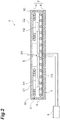
Fig. 2 is a cross-sectional view showing a configuration of the coil device. -
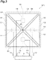
Fig. 3 is a plan view showing a main coil included in the coil device. -
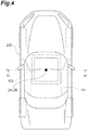
Fig. 4 is a diagram illustrating a case in which coils do not deviate from each other in the wireless power supply system. -
Fig. 5 is a conceptual diagram showing lines of magnetic force between a coil of a power transmitting device and a coil of a power receiving device inFig. 4 . -
Fig. 6 is a diagram illustrating a case in which the coils deviate from each other in the wireless power supply system s . -
Fig. 7 is a conceptual diagram showing lines of magnetic force between a coil of a power transmitting device and a coil of a power receiving device inFig. 6 . -
Fig. 8 is a plan view showing an arrangement of coils of a misalignment detection device according to a modified example. -
Fig. 9 is a plan view showing planar shapes of coils of a misalignment detection device according to another modified example. -
Fig. 10 is a cross-sectional view showing a configuration of a coil device according to still another modified example. - Hereinafter, a misalignment detection device and a coil device of the present disclosure will be described with reference to the drawings. Also, in the description of the drawings, the same elements will be denoted by the same reference numerals, and repeated descriptions thereof will be omitted.
- One aspect of the present disclosure is a misalignment detection device configured to detect misalignment of a second coil with respect to a first coil including a conductive wire wound around a coil axis. The misalignment detection device includes: a first induction heating unit and a second induction heating unit which receive lines of magnetic force generated by the first coil and are juxtaposed line-symmetrically with a second axis, which intersects the coil axis and a first axis intersecting the coil axis, being a line of symmetry; a first temperature measurement unit which is disposed adjacent to the first induction heating unit and outputs a first temperature; a second temperature measurement unit which is disposed adjacent to the second induction heating unit and outputs a second temperature; and a processing unit which detects misalignment of the second coil with respect to the first coil along the first axis on the basis of an evaluation value evaluating a difference between the first temperature and the second temperature.
- This device has the first induction heating unit and the second induction heating unit which are disposed line-symmetrically. These induction heating units generate heat when they receive the lines of magnetic force generated by the first coil. Further, the lines of magnetic force generated by the first coil correspond to a position of the second coil with respect to the first coil. That is, heating values of the first induction heating unit and the second induction heating unit depend on the lines of magnetic force provided to the respective induction heating units. As a result, temperatures corresponding to the heat generated by the respective induction heating units are acquired by the respective temperature measurement units. The acquired temperatures are provided to the processing unit. The processing unit can obtain the misalignment of the second coil with respect to the first coil on the basis of the evaluation value for evaluating the difference between the first temperature and the second temperature provided by the respective temperature measurement units. The first temperature is governed by the number of lines of magnetic force passing through the first induction heating unit, and the second temperature is governed by the number of lines of magnetic force passing through the second induction heating unit. That is, the first temperature and the second temperature are not easily affected by an environment in which the first coil and the second coil are disposed. Therefore, since the misalignment detection device is not affected by a state of an environment in which it is disposed, it is possible to perform positional misalignment detection that is not easily affected by surroundings.
- In one aspect, the first induction heating unit and the second induction heating unit may be coils. According to this configuration, induction heating in accordance with the lines of magnetic force can be appropriately generated.
- In one aspect, the evaluation value may be a difference obtained by subtracting one of the first temperature and the second temperature from the other. According to this evaluation value, the difference between the first temperature and the second temperature can be easily evaluated.
- In one aspect, the evaluation value may be a ratio of one of the first temperature and the second temperature to the other. With this evaluation value, the difference between the first temperature and the second temperature can be evaluated and the misalignment can be detected.
- The misalignment detection device according to one aspect may further include a third induction heating unit and a fourth induction heating unit which receive the lines of magnetic force generated by the first coil and are juxtaposed line-symmetrically with the first axis being the line of symmetry, a third temperature measurement unit which is disposed adjacent to the third induction heating unit and obtains a third temperature, and a fourth temperature measurement unit which is disposed adjacent to the fourth induction heating unit and obtains a fourth temperature. The processing unit may detect the misalignment of the second coil with respect to the first coil along the second axis on the basis of an evaluation value evaluating a difference between the third temperature and the fourth temperature. According to this configuration, the misalignment of the second coil with respect to the first coil along misalignment detection axes intersecting each other can be detected.
- Another aspect of the present disclosure is a coil device configured to perform transmission and reception of electric power to and from a counterpart coil. The coil device includes: a coil including a conductive wire wound around a coil axis; a first induction heating unit and a second induction heating unit which receive lines of magnetic force generated by the coil and are juxtaposed line-symmetrically with a second axis, which intersects the coil axis and a first axis intersecting the coil axis, being a line of symmetry; a first temperature measurement unit which is disposed adjacent to the first induction heating unit and outputs a first temperature; a second temperature measurement unit which is disposed adjacent to the second induction heating unit and outputs a second temperature; and a processing unit which detects misalignment of the counterpart coil with respect to the coil along the first axis on the basis of an evaluation value evaluating a difference between the first temperature and the second temperature.
- In this coil device, heating values generated in the first induction heating unit and the second induction heating unit vary depending on a form of the lines of magnetic force in accordance with a positional relationship between the coil and the counterpart coil. Temperatures caused by the heating values are acquired by a first temperature acquisition unit and a second temperature acquisition unit. As a result, the misalignment of the counterpart coil with respect to the coil can be detected on the basis of the difference between the first temperature and the second temperature provided by the respective temperature acquisition units. The first temperature is governed by the number of lines of magnetic force passing through the first induction heating unit, and the second temperature is governed by the number of lines of magnetic force passing through the second induction heating unit. That is, the first temperature and the second temperature are not easily affected by an environment in which the first coil and the second coil are disposed. Therefore, since the coil device is not affected by a state of an environment in which it is disposed, it is possible to perform positional misalignment detection that is not easily affected by surroundings.
- The coil device according to another aspect may further include a housing which accommodates the coil. According to this configuration, the coil can be protected.
- In another aspect, the housing may further accommodate the first induction heating unit, the second induction heating unit, the first temperature measurement unit, and the second temperature measurement unit. According to this configuration, the first induction heating unit, the second induction heating unit, the first temperature measurement unit, and the second temperature measurement unit can be protected.
- As shown in
Fig. 1 , acoil device 1 is used, for example, for apower transmitting device 101 or apower receiving device 102 in a wirelesspower supply system 100. The wirelesspower supply system 100 charges abattery 201 mounted in avehicle 200 such as an electric vehicle or a hybrid vehicle. Thecoil device 1 may be used for both thepower receiving device 102 and thepower transmitting device 101. - When the
coil device 1 is used for thepower transmitting device 101, thecoil device 1 serving as thepower transmitting device 101 is fixed to, for example, a road surface G. An external electric power source is connected to thecoil device 1 via a power transmitting circuit, a rectifying circuit, and the like. On the other hand, when thecoil device 1 is used for thepower receiving device 102, thecoil device 1 serving as thepower receiving device 102 is fixed to, for example, a chassis of thevehicle 200. Thebattery 201 is connected to thepower receiving device 102 via a power receiving circuit, a charging circuit, and the like. - The
power transmitting device 101 and thepower receiving device 102 face each other in a vertical direction. A power transmitting coil CA and a power receiving coil CB inside them are electromagnetically coupled to form an electromagnetic coupling circuit. As a result, wireless power supply is performed from the power transmitting coil CA of thepower transmitting device 101 to the power receiving coil CB of thepower receiving device 102. In other words, thepower receiving device 102 receives electric power from thepower transmitting device 101 in a non-contact manner. The electromagnetic coupling circuit may be a circuit that supplies electric power using an "electromagnetic induction" or may be a circuit that supplies electric power using a "magnetic resonance." - Hereinafter, the
coil device 1 will be described in more detail by exemplifying an aspect in which thecoil device 1 is used as thepower transmitting device 101. - A shape of the
coil device 1 is, for example, flat. As shown inFig. 2 , thecoil device 1 includes ahousing 2, the power transmitting coil CA (a first coil), and amisalignment detection device 3. - The
housing 2 accommodates at least the power transmitting coil CA. Thehousing 2 includes acover 4 and abase 6. At least the power transmitting coil CA is disposed in an accommodation space S surrounded by thecover 4 and thebase 6. - The
cover 4 is a box body disposed on a front surface side of the power transmitting coil CA. Thecover 4 is an exterior member. Thecover 4 protects interior parts including the power transmitting coil CA. Thecover 4 is made of, for example, a non-magnetic and non-conductive material. For the material of thecover 4, for example, glass fiber reinforced plastic (GFRP) may be used. - The
base 6 is a plate-shaped member disposed on a back surface side of the power transmitting coil CA. Thebase 6 secures rigidity of theentire coil device 1. A material of thebase 6 is, for example, non-magnetic and conductive. A material having a relatively high rigidity is used for the material of thebase 6. - For the material of the
base 6, for example, aluminum, which is a metal material having a low magnetic permeability, may be used. According to the selection of the material of thebase 6, thebase 6 can shield leaking magnetic flux from flowing to the outside. In other words, thebase 6 has a magnetic shielding property. - The
cover 4 and thebase 6 form the accommodation space S that accommodates the power transmitting coil CA and the like. When thecoil device 1 is applied to thepower transmitting device 101, thecover 4 faces thepower receiving device 102. Further, thebase 6 is disposed on a side fixed to the road surface G. In each flat portion of thecoil device 1, a surface close to and facing the other coil device is referred to as a "front surface." A surface away from other coil device, that is, a surface opposite to the front surface, is referred to as a "back surface." - The power transmitting coil CA transmits and receives electric power to and from the power receiving coil CB (a counterpart coil or a second coil; see
Fig. 1 ) included in thepower receiving device 102. The power transmitting coil CA generates magnetic flux for transmission and reception of the electric power. The power transmitting coil CA is formed, for example, by aconductive wire 7 wound in a substantially rectangular spiral shape in the same plane. The power transmitting coil CA is, for example, a circular coil. In the circular coil, theconductive wire 7 is wound in a winding direction to surround a winding axis ZA (a coil axis). In this case, the winding direction is a direction extending in a spiral shape and is a direction along a plane perpendicular to the winding axis ZA. For theconductive wire 7, for example, a litz wire in which a plurality of conductor strands insulated from each other are twisted is used. For theconductive wire 7, a litz wire having inhibited high frequency resistance due to the skin effect may be used. For theconductive wire 7, a single wire made of copper or aluminum may be used. - The power transmitting coil CA is fitted, for example, in a groove of a
bobbin 8 which is a flat plate-shaped member. Thebobbin 8 is made of a non-magnetic and non-conductive material. Examples of the non-magnetic and non-conductive material include silicone and a polyphenylene sulfide resin. By fixing thebobbin 8 to thebase 6, a position of the power transmitting coil CA in the accommodation space S is determined. If necessary, a ferrite plate may be provided between thebobbin 8 and thebase 6. In other words, the ferrite plate may be disposed between the power transmitting coil CA and thebase 6. The ferrite plate may be substantially equal in size to thebobbin 8. Further, the ferrite plate may be larger than thebobbin 8. Thebobbin 8 is interposed between the ferrite plate and the power transmitting coil CA. Therefore, the power transmitting coil CA does not abut the ferrite plate. The power transmitting coil CA may abut the ferrite plate. - As shown in
Figs. 2 and3 , themisalignment detection device 3 includes coils C1, C2, C3, and C4, temperature sensors H1, H2, H3, and H4, and a processing device 9 (a processing unit). The coil C1 is a first induction heating unit. The coil C2 is a second induction heating unit. The coil C3 is a third induction heating unit. The coil C4 is a fourth induction heating unit. The temperature sensor H1 is a first temperature measurement unit. The temperature sensor H2 is a second temperature measurement unit. The temperature sensor H3 is a third temperature measurement unit. The temperature sensor H4 is a fourth temperature measurement unit. The coils C1, C2, C3, and C4 and the temperature sensors H1, H2, H3, and H4 are accommodated inside thehousing 2. Also, theprocessing device 9 may not be accommodated in thehousing 2. Theprocessing device 9 may be accommodated in thehousing 2. - The
misalignment detection device 3 has the winding axis ZA, an axis line XA (a first axis), and an axis line YA (a second axis). The axis lines XA and YA are misalignment detection axes in themisalignment detection device 3. Further, the axis lines XA and YA are also a line of symmetry. The axis line XA is orthogonal to (intersects) the axis line YA and the winding axis ZA. The axis line YA is orthogonal to (intersects) the axis line XA and the winding axis ZA. The winding axis ZA and the axis lines XA and YA form a three-axis orthogonal coordinate system. - The
misalignment detection device 3 detects misalignment of the power receiving coil CB of thepower receiving device 102 with respect to the power transmitting coil CA of thepower transmitting device 101. The "misalignment" referred to here may be defined as, for example, a relative position of a winding axis ZB of the power receiving coil CB with respect to the winding axis ZA of the power transmitting coil CA. That is, when the winding axis ZA of the power transmitting coil CA is on the same straight line as the winding axis ZB of the power receiving coil CB (seeFig. 4 ), there may be no "misalignment." On the other hand, when the winding axis ZA of the power transmitting coil CA is not on the same straight line as the winding axis ZB of the power receiving coil CB (seeFIG. 6 ), there may be "misalignment." In other words, when the power transmitting coil CA and the power receiving coil CB are viewed in a plan view and the winding axis ZA of the power transmitting coil CA and the winding axis ZB of the power receiving coil CB are located at different positions, it may be determined that there is "misalignment." Also, the definition of "misalignment" may be based on configurations different from those of the winding axes ZA and ZB. For example, a positional relationship between the power transmitting coil CA and the power receiving coil CB, at which a desired transmission efficiency is achieved, may not be "misalignment." For example, for a positional relationship that maximizes the transmission efficiency, it may be determined that there is no "misalignment." Further, for a positional relationship that does not achieve the desired transmission efficiency, it may be determined that there is "misalignment." - The misalignment of the power receiving coil CB with respect to the power transmitting coil CA is indicated by misalignment along the axis line XA and misalignment along the axis line YA. Therefore, the misalignment detection axis is defined as a reference for indicating this misalignment.
- The
misalignment detection device 3 detects the misalignment in a direction of the axis line XA using the coils C1 and C2 and the temperature sensors H1 and H2. The coils C1 and C2 are juxtaposed along the axis line XA with the axis line XA set as the misalignment detection axis. The coils C1 and C2 are disposed line-symmetrically with the axis line YA set as the axis of symmetry when viewed in a plan view in a direction of the winding axis ZA. The coils C1 and C2 are disposed on both sides of the winding axis ZA with the winding axis ZA interposed therebetween. Line symmetry includes symmetry between positions at which the coils C1 and C2 are disposed. Further, line symmetry also includes symmetry between planar shapes of the coils C1 and C2. - The
misalignment detection device 3 detects the misalignment in a direction of the axis line YA using the coils C3 and C4 and the temperature sensors H3 and H4. The coils C3 and C4 are juxtaposed along the axis line YA with the axis line YA set as the misalignment detection axis. The coils C3 and C4 are disposed line-symmetrically with the axis XA set as the axis of symmetry when viewed in a plan view in the direction of the winding axis ZA. The coils C3 and C4 are disposed on both sides of the winding axis ZA with the winding axis ZA interposed therebetween. - The coils C1, C2, C3, and C4 are configured of wound conductive wires like the power transmitting coil CA and the power receiving coil CB. In
Fig. 3 , outer shapes of the coils C1, C2, C3, and C4 are shown as triangles with solid lines. That is, the coils C1, C2, C3, and C4 inFig. 3 are not shown with the wound conductive wires. According to the illustration ofFig. 3 , the coils C1, C2, C3, and C4 have isosceles triangle shapes when viewed in a plan view. As described above, the arrangement of the coils C1, C2, C3 and C4 is line symmetric. Therefore, the planar shapes of the coils C1, C2, C3, and C4 are congruent with each other. - The coils C1, C2, C3 and C4 are held by bobbins B1, B2, B3 and B4. The bobbins B1, B2, B3, and B4 are separate from each other. In addition, the bobbins B1, B2, B3, and B4 may be disposed with gaps provided therebetween. According to this arrangement, the coils C1, C2, C3, and C4 and the bobbins B1, B2, B3, and B4 can be formed to be thermally independent from each other. Therefore, differences in temperature between the coils C1, C2, C3 and C4 and between the bobbins B1, B2, B3 and B4 can be appropriately generated.
- The bobbins B1, B2, B3, and B4 that hold the coils C1, C2, C3, and C4 are attached to a back surface of the cover 4 (see
Fig. 2 ). The coils C1, C2, C3, and C4 are disposed above the power transmitting coil CA. In other words, the coils C1, C2, C3, and C4 are disposed to be separated from the power transmitting coil CA in the direction of the winding axis ZA of the power transmitting coil CA. According to this arrangement, the coils C1, C2, C3 and C4 face the power transmitting coil CA. - The temperature sensors H1, H2, H3, and H4 output data related to temperatures to the
processing device 9. The temperature sensors H1, H2, H3, and H4 are disposed adjacent to the coils C1, C2, C3, and C4, respectively. Specifically, the temperature sensors H1, H2, H3, and H4 are attached to back surfaces of the bobbins B1, B2, B3, and B4. Also, the temperature sensors H1, H2, H3, and H4 may be embedded in the bobbins B1, B2, B3, and B4. - Positions at which the temperature sensors H1, H2, H3, and H4 are provided are positions at which temperatures of the coils C1, C2, C3, and C4 can be acquired. The fact that each temperature can be acquired means that, for example, the temperature sensor H1 acquires a temperature at which heat generated by the coil C1 is dominant. In other words, the temperature at the position at which the temperature sensor H1 is provided is a temperature when influence of the heat generated by the coil C1 is dominant and influence of the heat generated by the coils C2, C3, and C4 is in a negligible range as compared with that of the heat generated by the coil C1. For example, providing the temperature sensor H1 adjacent to the coil C1 may mean disposing the temperature sensor H1 at a position at which the heat generated by the coil C1 is dominant. Therefore, the temperature sensors H1, H2, H3, and H4 may not be disposed close to each other, but may be disposed to be largely separated from each other.
- The
processing device 9 detects presence or absence of the misalignment using the temperature T1 (a first temperature), the temperature T2 (a second temperature), the temperature T3 (a third temperature), and the temperature T4 (a fourth temperature) which are provided by the temperature sensors H1, H2, H3, and H4. Theprocessing device 9 is, for example, an arbitrary suitable processor such as a central processing unit (CPU) or a dedicated processor specialized for each type of processing (for example, a digital signal processor (DSP)). Theprocessing device 9 can appropriately include a read only memory (ROM) and a random access memory (RAM) for executing the processing. - A case in which there is no misalignment will be illustrated. As shown in
Fig. 4 , the winding axis ZB of thepower receiving device 102 mounted in thevehicle 200 coincides with the winding axis ZA of thepower transmitting device 101 embedded in the road surface G.Fig. 5 shows cross-sections of thepower receiving device 102 and thepower transmitting device 101 along line IV-IV. InFig. 5 , only the power receiving coil CB of thepower receiving device 102, the power transmitting coil CA of thepower transmitting device 101, and the coils C1 and C2 are shown. -
Fig. 5 shows lines of magnetic force M generated between the power transmitting coil CA and the power receiving coil CB. The coils C1 and C2 are present between the power transmitting coil CA and the power receiving coil CB. Therefore, the lines of magnetic force M pass through the coils C1 and C2. Here, when the power receiving coil CB is not misaligned with the power transmitting coil CA, the lines of magnetic force M are symmetrical with respect to the winding axes ZA and ZB. In other words, the number of the lines of magnetic force M passing through the coil C1 is the same as the number of the lines of magnetic force M passing through the coil C2. For example, in the example shown inFig. 5 , nine lines of magnetic force M pass through each of the coils C1 and C2. - When the lines of magnetic force M pass through the coils C1 and C2, induced currents are generated in the coils C1 and C2. Magnitudes of the induced currents depend on the number of the lines of magnetic force M passing through the coils C1 and C2. In the example shown in
Fig. 5 , nine lines of magnetic force M pass through each of the coils C1 and C2. Therefore, the magnitude of the induced current generated in the coil C1 is the same as the magnitude of the induced current generated in the coil C2. When the induced currents are generated in the coils C1 and C2, the coils C1 and C2 generate heat. These heating values depend on the magnitudes of the induced currents. As described above, since the magnitudes of the induced currents generated in the coils C1 and C2 are the same, the heating values of the coils C1 and C2 are also the same. As a result, the temperature of the coil C1 is the same as the temperature of the coil C2. - In the present disclosure, the coils C1 and C2 have been shown as examples of the induction heating units. The
misalignment detection device 3 utilizes the heat generated in accordance with the lines of magnetic force M passing therethrough. Therefore, the induction heating units are not limited to the coils as long as heat generation corresponding to the lines of magnetic force M can be obtained. For example, the induction heating units may be metal ring-shaped members. - Next, a case in which there is misalignment will be illustrated. As shown in
Fig. 6 , the winding axis ZB of thepower receiving device 102 mounted in thevehicle 200 is misaligned with the winding axis ZA of thepower transmitting device 101 embedded in the road surface G (see misalignment D).Fig. 7 shows a cross-section of thepower receiving device 102 and thepower transmitting device 101 along line VI-VI. - As shown in
Fig. 7 , when the power receiving coil CB is misaligned with the power transmitting coil CA, the lines of magnetic force M are not symmetrical with respect to the winding axes ZA and ZB. The lines of magnetic force M are emitted from the power transmitting coil CA and directed to the power receiving coil CB. However, since the power receiving coil CB is misaligned with the power transmitting coil CA, a distribution of the lines of magnetic force M is not symmetrical. As a result, there is a difference between the number of the lines of magnetic force M passing through the coil C1 and the number of the lines of magnetic force M passing through the coil C2. In the example ofFig. 7 , the number of the lines of magnetic force M passing through the coil C1 is eight. On the other hand, the number of the lines of magnetic force M passing through the coil C2 is ten. - When the numbers of the lines of magnetic force M passing through the coils C1 and C2 are different from each other, the magnitudes of the induced currents generated in the coils C1 and C2 are also different from each other. As a result, the heating values of the coils C1 and C2 due to the induced currents are also different from each other. Therefore, as a result, the temperature T1 related to the coil C1 is different from the temperature T2 related to the coil C2 (T1<T2). In other words, the temperature of the bobbin B1 is different from the temperature of the bobbin B2.
- That is, by evaluating the difference in temperature between the coils C1 and C2, it is possible to detect presence or absence of the misalignment of the power receiving coil CB with respect to the power transmitting coil CA. In other words, by evaluating the difference in temperature between the bobbins B1 and B2, it is possible to detect presence or absence of the misalignment of the power receiving coil CB with respect to the power transmitting coil CA. The
processing device 9 detects presence or absence of the misalignment by using an evaluation value for evaluating the difference between the temperature T1 of the coil C1 and the temperature T2 of the coil C2. - The
processing device 9 uses the difference between the temperature T1 of the coil C1 and the temperature T2 of the coil C2 as the evaluation value. In other words, theprocessing device 9 uses the difference between the temperature T1 of the bobbin B1 and the temperature T2 of the bobbin B2 as the evaluation value. For example, the temperature T2 of the coil C2 is subtracted from the temperature T1 of the coil C1. In other words, the temperature T2 of the bobbin B2 is subtracted from the temperature T1 of the bobbin B1. As a result, a difference ΔT (T1-T2) is obtained. When an absolute value |ΔT| of the difference ΔT is included in a preset range (0≤|ΔT|≤Tth), theprocessing device 9 may determine that there is no misalignment. On the other hand, when the difference ΔT is not included in the preset range (Tth<|ΔT|), theprocessing device 9 may determine that there is misalignment. Further, theprocessing device 9 may specify a direction of the misalignment on the basis of a sign (positive or negative) of the difference ΔT. - In short, the
coil device 1 and themisalignment detection device 3 have the coils C1 and C2 and the coils C3 and C4 which are disposed line-symmetrically. When these coils C1, C2, C3, and C4 receive the lines of magnetic force M generated by the power transmitting coil CA, induced currents are generated, and the induced currents generate heat. In addition, the lines of magnetic force M generated by the power transmitting coil CA correspond to a position of the power receiving coil CB with respect to the power transmitting coil CA. That is, the heating values of the coils C1, C2, C3, and C4 depend on the number of the lines of magnetic force M provided to the respective coils C1, C2, C3, and C4. As a result, the temperatures corresponding to the heat generated by the respective coils C1, C2, C3, and C4 are acquired by the respective temperature sensors H1, H2, H3, and H4. The acquired temperatures T1, T2, T3, and T4 are provided to theprocessing device 9. Then, theprocessing device 9 can obtain the misalignment of the power receiving coil CB with respect to the power transmitting coil CA on the basis of the temperatures T1, T2, T3, and T4 provided by the respective temperature sensors H1, H2, H3, and H4 and the difference ΔT to be evaluated. The temperatures T1, T2, T3, and T4 are governed by the number of the lines of magnetic force M passing through the coils C1, C2, C3, and C4, respectively. Therefore, the temperatures T1, T2, T3, and T4 are not easily affected by an environment in which the power transmitting coil CA and the power receiving coil CB are disposed. Accordingly, since thecoil device 1 and themisalignment detection device 3 are not affected by the state of an environment in which they are installed, it is possible to perform positional misalignment detection that is not easily affected by surroundings. - The
misalignment detection device 3 detects the misalignment of the power transmitting coil CA and the power receiving coil CB in accordance with the heat generated by the coils C1, C2, C3, and C4. Therefore, themisalignment detection device 3 does not need to use image processing using a camera. As a result, it is relatively simple to perform configuring and processing of themisalignment detection device 3 as compared with a configuration using a camera. As a result, themisalignment detection device 3 can reduce costs. Further, themisalignment detection device 3 is not easily affected by dust and dirt. As a result, themisalignment detection device 3 can perform positional misalignment detection that is not easily affected by surroundings. - The first induction heating unit and the second induction heating unit are the coils C1 and C2. According to this configuration, induction heating in accordance with the lines of magnetic force M can be appropriately generated.
- The evaluation value is the difference ΔT obtained by subtracting one of the temperatures T1 and T2 from the other. According to this evaluation value, the difference between the temperatures T1 and T2 can be easily evaluated.
- The
coil device 1 includes thehousing 2 that accommodates the power transmitting coil CA. According to this configuration, the power transmitting coil CA can be protected. - The
housing 2 accommodates the coils C1, C2, C3, and C4 and the temperature sensors H1, H2, H3, and H4. According to this configuration, the coils C1, C2, C3, and C4 and the temperature sensors H1, H2, H3, and H4 can be protected. - Although the
coil device 1 and themisalignment detection device 3 of the present disclosure have been described, thecoil device 1 and themisalignment detection device 3 of the present disclosure are not limited to the above aspects. - For example, as a value for evaluating the difference in temperature, a ratio between the temperatures T1 and T2 (T2/T1) may be used instead of the difference ΔT in temperature. Presence or absence of the misalignment can be appropriately detected also with this evaluation value. For example, a temperature generated in a case in which the maximum allowable misalignment occurs is calculated in advance through actual measurement or analysis. Then, a threshold ratio is obtained from the obtained temperature. Here, provided that temperatures T1R and T2R are obtained when the maximum misalignment occurs in one direction (for example, a rightward direction of the paper surface in
Fig. 7 ), the threshold ratio in one direction is (TSR=T2R/T1R). On the other hand, provided that temperatures TIL and T2L are obtained when the maximum misalignment occurs in the other direction (for example, a leftward direction of the paper surface inFig. 7 ), the threshold ratio in the other direction is (TSL=T2L/T1L). Then, theprocessing device 9 compares the ratio (T2/T1) obtained when the coils are operated with the threshold ratio (TSR and TSL). Specifically, theprocessing device 9 may determine that there is no misalignment when the ratio (T2/T1) is included in a range indicated by the threshold ratio (TSL≤(T2/T1)≤TSR). On the other hand, when the ratio (T2/T1) is not included in the range indicated by the threshold ratio ((T2/T1)<TSL or TSR<(T2/T1)), theprocessing device 9 may determine that there is misalignment. - As shown in part (a) of
Fig. 8 and part (b) ofFig. 8 , the number of the misalignment detection axes included in themisalignment detection devices misalignment detection device 3A shown in part (a) ofFig. 8 uses the axis line XA as the misalignment detection axis. Themisalignment detection device 3A has the axis line YA as the axis of symmetry. Themisalignment detection device 3B shown in part (b) ofFig. 8 uses the axis line YA as the misalignment detection axis. Themisalignment detection device 3B has the axis line XA as the axis of symmetry. According to such a configuration, the configuration of themisalignment detection devices - As shown in part (a) of
Fig. 9 , part (b) ofFig. 9 , part (c) ofFig. 9 , and part (d) ofFig. 9 , a planar shape of each coil ofmisalignment detection devices Fig. 9 , coils C1c, C2c, C3c, and C4c of themisalignment detection device 3C may each have a trapezoidal shape. The coils C1c, C2c, C3c, and C4c may be disposed along an outer edge portion of the power transmitting coil CA. As shown in part (b) ofFig. 9 , coils C1d, C2d, C3d, and C4d of themisalignment detection device 3D may have rectangular shapes. As shown in part (c) ofFig. 9 , coils C1e, C2e, C3e, and C4e of themisalignment detection device 3E may have elliptical shapes. As shown in part (d) ofFig. 9 , coils C1f, C2f, C3f, and C4f of themisalignment detection device 3F may have circular shapes. Axis lines XB and YB of themisalignment detection device 3F shown in part (d) ofFig. 9 may be diagonal lines in a square-shaped power transmitting coil CA. According to the configuration of the axes XB and YB, the coils C1f and C2f are disposed with the axis line YB set as the axis of symmetry. In addition, the axis line XB serves as the misalignment detection axis. The coils C3f and C4f are disposed with the axis line XB set as the axis of symmetry. The axis line YB serves as the misalignment detection axis. Themisalignment detection devices - As shown in
Fig. 10 , coils C1g and C2g of themisalignment detection device 3G and temperature sensors H1g and H2g may be disposed outside thehousing 2. According to this configuration, it is possible to obtain acoil device 1G in which amisalignment detection device 3G is retrofitted to an existing coil device. -
- 1 Coil device
- 2 Housing
- 3, 3A, 3B, 3C, 3D, 3E, 3F, 3G Misalignment detection device
- 4 Cover
- 6 Base
- 7 Conductive wire
- 8 Bobbin
- 9 Processing device (processing unit)
- 100 Wireless power supply system
- 101 Power transmitting device
- 102 Power receiving device
- 200 Vehicle
- 201 Battery
- B1, B2, B4, B4 Bobbin
- CA Power transmitting coil (first coil)
- CB Power receiving coil (second coil or counterpart coil)
- C1 Coil (first induction heating unit)
- C2 Coil (second induction heating unit)
- C3 Coil (third induction heating unit)
- C4 Coil (fourth induction heating unit)
- G Road surface
- H1, H1g Temperature sensor (first temperature measurement unit)
- H2, H2g Temperature sensor (second temperature measurement unit)
- H3 Temperature sensor (third temperature measurement unit)
- H4 Temperature sensor (fourth temperature measurement unit)
- S Accommodation space
- T1 Temperature (first temperature)
- T2 Temperature (second temperature)
- T3 Temperature (third temperature)
- T4 Temperature (fourth temperature)
- M Lines of magnetic force
- XA, XB Axis line (first axis)
- YA, YB Axis line (second axis)
- ZA, ZB Winding axis (coil axis)
Claims (8)
- A misalignment detection device configured to detect misalignment of a second coil with respect to a first coil including a conductive wire wound around a coil axis, comprising:a first induction heating unit and a second induction heating unit which receive lines of magnetic force generated by the first coil and are juxtaposed line-symmetrically with a second axis, which intersects the coil axis and a first axis intersecting the coil axis, being a line of symmetry;a first temperature measurement unit which is disposed adjacent to the first induction heating unit and outputs a first temperature;a second temperature measurement unit which is disposed adjacent to the second induction heating unit and outputs a second temperature; anda processing unit which detects misalignment of the second coil with respect to the first coil along the first axis on the basis of an evaluation value evaluating a difference between the first temperature and the second temperature.
- The misalignment detection device according to claim 1, wherein the first induction heating unit and the second induction heating unit are coils.
- The misalignment detection device according to claim 1 or 2, wherein the evaluation value is a difference obtained by subtracting one of the first temperature and the second temperature from the other.
- The misalignment detection device according to claim 1 or 2, wherein the evaluation value is a ratio of one of the first temperature and the second temperature to the other.
- The misalignment detection device according to any one of claims 1 to 4, further comprising:a third induction heating unit and a fourth induction heating unit which receive the lines of magnetic force generated by the first coil and are juxtaposed line-symmetrically with the first axis being the line of symmetry;a third temperature measurement unit which is disposed adjacent to the third induction heating unit and obtains a third temperature; anda fourth temperature measurement unit which is disposed adjacent to the fourth induction heating unit and obtains a fourth temperature,wherein the processing unit detects the misalignment of the second coil with respect to the first coil along the second axis on the basis of an evaluation value evaluating a difference between the third temperature and the fourth temperature.
- A coil device configured to perform transmission and reception of electric power to and from a counterpart coil, comprising:a coil including a conductive wire wound around a coil axis;a first induction heating unit and a second induction heating unit which receive lines of magnetic force generated by the coil and are juxtaposed line-symmetrically with a second axis, which intersects the coil axis and a first axis intersecting the coil axis, being a line of symmetry;a first temperature measurement unit which is disposed adjacent to the first induction heating unit and outputs a first temperature;a second temperature measurement unit which is disposed adjacent to the second induction heating unit and outputs a second temperature; anda processing unit which detects misalignment of the counterpart coil with respect to the coil along the first axis on the basis of an evaluation value evaluating a difference between the first temperature and the second temperature.
- The coil device according to claim 6, further comprising a housing which accommodates the coil.
- The coil device according to claim 7, wherein the housing further accommodates the first induction heating unit, the second induction heating unit, the first temperature measurement unit, and the second temperature measurement unit.
Applications Claiming Priority (2)
| Application Number | Priority Date | Filing Date | Title |
|---|---|---|---|
| JP2018189910 | 2018-10-05 | ||
| PCT/JP2019/027976 WO2020070945A1 (en) | 2018-10-05 | 2019-07-16 | Misalignment detection device and coil device |
Publications (2)
| Publication Number | Publication Date |
|---|---|
| EP3863150A1 true EP3863150A1 (en) | 2021-08-11 |
| EP3863150A4 EP3863150A4 (en) | 2022-06-15 |
Family
ID=70055383
Family Applications (1)
| Application Number | Title | Priority Date | Filing Date |
|---|---|---|---|
| EP19868509.1A Pending EP3863150A4 (en) | 2018-10-05 | 2019-07-16 | Misalignment detection device and coil device |
Country Status (4)
| Country | Link |
|---|---|
| US (1) | US11912149B2 (en) |
| EP (1) | EP3863150A4 (en) |
| JP (1) | JP7036222B2 (en) |
| WO (1) | WO2020070945A1 (en) |
Cited By (1)
| Publication number | Priority date | Publication date | Assignee | Title |
|---|---|---|---|---|
| EP4583366A4 (en) * | 2022-10-06 | 2026-01-14 | Samsung Electronics Co Ltd | ELECTRONIC DEVICE WITH MULTI-COILS |
Families Citing this family (2)
| Publication number | Priority date | Publication date | Assignee | Title |
|---|---|---|---|---|
| CN113858982B (en) * | 2021-09-14 | 2024-04-05 | 合肥有感科技有限责任公司 | Wireless charging foreign matter detection method |
| CN115593262B (en) * | 2022-11-18 | 2023-04-07 | 国网天津市电力公司滨海供电分公司 | Electric automobile charging method, device, system, robot and station yard |
Family Cites Families (15)
| Publication number | Priority date | Publication date | Assignee | Title |
|---|---|---|---|---|
| JPS55146121A (en) | 1979-05-04 | 1980-11-14 | Otsuka Hiroshi | Automatic pillow |
| JP2008017562A (en) | 2006-07-03 | 2008-01-24 | Mitsubishi Electric Corp | Contactless charger |
| JP2010080770A (en) | 2008-09-26 | 2010-04-08 | Alps Electric Co Ltd | Electronic circuit module and method of inspecting the same |
| WO2010098397A1 (en) | 2009-02-25 | 2010-09-02 | マスプロ電工株式会社 | Power supply system of mobile unit |
| JP4905571B2 (en) | 2010-03-10 | 2012-03-28 | トヨタ自動車株式会社 | Vehicle parking assistance device and vehicle equipped with the same |
| JP5749208B2 (en) | 2012-03-26 | 2015-07-15 | 株式会社東芝 | Power transmission device, power reception device, control device, and wireless power transmission system |
| US9755436B2 (en) | 2013-02-14 | 2017-09-05 | Toyota Jidosha Kabushiki Kaisha | Power receiving device and power transmitting device |
| JP6147112B2 (en) * | 2013-06-25 | 2017-06-14 | ローム株式会社 | Wireless power transmission apparatus and control method thereof |
| JP2015100230A (en) | 2013-11-20 | 2015-05-28 | トヨタ自動車株式会社 | Non-contact power transmission and reception system |
| JP6330637B2 (en) * | 2014-11-28 | 2018-05-30 | トヨタ自動車株式会社 | Power receiving device |
| JP6176272B2 (en) * | 2015-02-27 | 2017-08-09 | トヨタ自動車株式会社 | Power transmission system |
| CN107580742B (en) * | 2015-04-07 | 2019-01-18 | 日产自动车株式会社 | The temperature estimation rneans and temperature estimation method of non-contact power receiving device |
| JP6474527B2 (en) * | 2016-02-24 | 2019-02-27 | ローム株式会社 | Wireless power transmission device and charger |
| KR102546697B1 (en) * | 2016-06-16 | 2023-06-21 | 현대자동차주식회사 | Coil alignment method in wireless power transfer system and apparatus using the same |
| JP7059887B2 (en) * | 2018-10-12 | 2022-04-26 | トヨタ自動車株式会社 | Power receiving device, power transmission system, and control method of power receiving device |
-
2019
- 2019-07-16 JP JP2020549966A patent/JP7036222B2/en active Active
- 2019-07-16 WO PCT/JP2019/027976 patent/WO2020070945A1/en not_active Ceased
- 2019-07-16 US US17/269,565 patent/US11912149B2/en active Active
- 2019-07-16 EP EP19868509.1A patent/EP3863150A4/en active Pending
Cited By (1)
| Publication number | Priority date | Publication date | Assignee | Title |
|---|---|---|---|---|
| EP4583366A4 (en) * | 2022-10-06 | 2026-01-14 | Samsung Electronics Co Ltd | ELECTRONIC DEVICE WITH MULTI-COILS |
Also Published As
| Publication number | Publication date |
|---|---|
| EP3863150A4 (en) | 2022-06-15 |
| JP7036222B2 (en) | 2022-03-15 |
| US11912149B2 (en) | 2024-02-27 |
| JPWO2020070945A1 (en) | 2021-09-02 |
| US20210323428A1 (en) | 2021-10-21 |
| WO2020070945A1 (en) | 2020-04-09 |
Similar Documents
| Publication | Publication Date | Title |
|---|---|---|
| US9950636B2 (en) | Foreign matter detection device and method for wireless power supply device | |
| US11264834B2 (en) | Coil apparatus | |
| JP4772744B2 (en) | Signal transmission coil communication device for non-contact power feeding device | |
| CN109313975B (en) | Coil device and holding member | |
| US11322984B2 (en) | Coil device | |
| US11912149B2 (en) | Misalignment detection device and coil device | |
| ES2750628T3 (en) | Acoustic electromagnetic transducer | |
| JP6131588B2 (en) | Current sensor | |
| CN105264389B (en) | Current measuring device and current calculation method | |
| US11841258B2 (en) | Coriolis measuring sensor and coriolis measuring device having a coriolis measuring sensor | |
| JP6179160B2 (en) | Wireless power transmission equipment | |
| US20140230565A1 (en) | Magneto Inductive Flow Measuring Device | |
| EP1357513A2 (en) | Noncontact sensor coil and tag system | |
| US20210215845A1 (en) | Foreign Object Detector, Wireless Power Transmission System Comprising a Foreign Object Detector and Method of Detecting a Foreign Object | |
| JP2019526805A (en) | Apparatus and method for measuring the current intensity of one individual conductor of a multiconductor system | |
| CN116806403A (en) | Method and device for recovering electrical energy for single-phase or multiphase power cables | |
| KR20200060275A (en) | Magnetic core for a current measurement sensor | |
| CA2951066A1 (en) | Measuring arrangement for detecting a magnetic unidirectional flux in the core of a transformer | |
| US20220258621A1 (en) | Coil device, power supply device, and detection device | |
| JP2014085248A (en) | Current sensor and current detection method | |
| EP2921864B1 (en) | Current Sensor | |
| US10379138B2 (en) | Adapter for receiving an integrated circuit | |
| JP6631903B2 (en) | Current sensor and distribution board equipped with it | |
| EP3982381A1 (en) | Power transformer | |
| JP6172567B2 (en) | Foreign object detection device and method for non-contact power feeding device |
Legal Events
| Date | Code | Title | Description |
|---|---|---|---|
| STAA | Information on the status of an ep patent application or granted ep patent |
Free format text: STATUS: THE INTERNATIONAL PUBLICATION HAS BEEN MADE |
|
| PUAI | Public reference made under article 153(3) epc to a published international application that has entered the european phase |
Free format text: ORIGINAL CODE: 0009012 |
|
| STAA | Information on the status of an ep patent application or granted ep patent |
Free format text: STATUS: REQUEST FOR EXAMINATION WAS MADE |
|
| 17P | Request for examination filed |
Effective date: 20210420 |
|
| AK | Designated contracting states |
Kind code of ref document: A1 Designated state(s): AL AT BE BG CH CY CZ DE DK EE ES FI FR GB GR HR HU IE IS IT LI LT LU LV MC MK MT NL NO PL PT RO RS SE SI SK SM TR |
|
| DAV | Request for validation of the european patent (deleted) | ||
| DAX | Request for extension of the european patent (deleted) | ||
| A4 | Supplementary search report drawn up and despatched |
Effective date: 20220518 |
|
| RIC1 | Information provided on ipc code assigned before grant |
Ipc: H02J 7/02 20160101ALI20220512BHEP Ipc: H01F 7/06 20060101ALI20220512BHEP Ipc: H01F 27/40 20060101ALI20220512BHEP Ipc: H01F 27/38 20060101ALI20220512BHEP Ipc: H01F 7/127 20060101ALI20220512BHEP Ipc: H01F 7/126 20060101ALI20220512BHEP Ipc: B60L 53/38 20190101ALI20220512BHEP Ipc: B60L 53/12 20190101ALI20220512BHEP Ipc: H02J 50/00 20160101ALI20220512BHEP Ipc: B60M 7/00 20060101ALI20220512BHEP Ipc: B60L 53/36 20190101ALI20220512BHEP Ipc: B60L 5/00 20060101ALI20220512BHEP Ipc: H02J 50/10 20160101ALI20220512BHEP Ipc: H02J 7/00 20060101ALI20220512BHEP Ipc: H01F 38/14 20060101ALI20220512BHEP Ipc: H02J 50/90 20160101AFI20220512BHEP |