EP3863143B1 - Power supply device - Google Patents
Power supply device Download PDFInfo
- Publication number
- EP3863143B1 EP3863143B1 EP21155749.1A EP21155749A EP3863143B1 EP 3863143 B1 EP3863143 B1 EP 3863143B1 EP 21155749 A EP21155749 A EP 21155749A EP 3863143 B1 EP3863143 B1 EP 3863143B1
- Authority
- EP
- European Patent Office
- Prior art keywords
- battery
- voltage
- controller
- batteries
- connection
- Prior art date
- Legal status (The legal status is an assumption and is not a legal conclusion. Google has not performed a legal analysis and makes no representation as to the accuracy of the status listed.)
- Active
Links
Images


Classifications
-
- H—ELECTRICITY
- H02—GENERATION; CONVERSION OR DISTRIBUTION OF ELECTRIC POWER
- H02J—ELECTRIC POWER NETWORKS; CIRCUIT ARRANGEMENTS OR SYSTEMS FOR SUPPLYING OR DISTRIBUTING ELECTRIC POWER; SYSTEMS FOR STORING ELECTRIC ENERGY
- H02J7/00—Circuit arrangements for charging or discharging batteries or for supplying loads from batteries
- H02J7/50—Circuit arrangements for charging or discharging batteries or for supplying loads from batteries acting upon multiple batteries simultaneously or sequentially
- H02J7/575—Parallel/serial switching of connection of batteries to charge or load circuit
-
- H—ELECTRICITY
- H02—GENERATION; CONVERSION OR DISTRIBUTION OF ELECTRIC POWER
- H02J—ELECTRIC POWER NETWORKS; CIRCUIT ARRANGEMENTS OR SYSTEMS FOR SUPPLYING OR DISTRIBUTING ELECTRIC POWER; SYSTEMS FOR STORING ELECTRIC ENERGY
- H02J7/00—Circuit arrangements for charging or discharging batteries or for supplying loads from batteries
- H02J7/50—Circuit arrangements for charging or discharging batteries or for supplying loads from batteries acting upon multiple batteries simultaneously or sequentially
- H02J7/52—Circuit arrangements for charging or discharging batteries or for supplying loads from batteries acting upon multiple batteries simultaneously or sequentially for charge balancing, e.g. equalisation of charge between batteries
-
- H—ELECTRICITY
- H02—GENERATION; CONVERSION OR DISTRIBUTION OF ELECTRIC POWER
- H02J—ELECTRIC POWER NETWORKS; CIRCUIT ARRANGEMENTS OR SYSTEMS FOR SUPPLYING OR DISTRIBUTING ELECTRIC POWER; SYSTEMS FOR STORING ELECTRIC ENERGY
- H02J7/00—Circuit arrangements for charging or discharging batteries or for supplying loads from batteries
- H02J7/80—Circuit arrangements for charging or discharging batteries or for supplying loads from batteries including monitoring or indicating arrangements
- H02J7/82—Control of state of charge [SOC]
-
- H—ELECTRICITY
- H02—GENERATION; CONVERSION OR DISTRIBUTION OF ELECTRIC POWER
- H02J—ELECTRIC POWER NETWORKS; CIRCUIT ARRANGEMENTS OR SYSTEMS FOR SUPPLYING OR DISTRIBUTING ELECTRIC POWER; SYSTEMS FOR STORING ELECTRIC ENERGY
- H02J7/00—Circuit arrangements for charging or discharging batteries or for supplying loads from batteries
- H02J7/865—Battery or charger load switching, e.g. concurrent charging and load supply
-
- Y—GENERAL TAGGING OF NEW TECHNOLOGICAL DEVELOPMENTS; GENERAL TAGGING OF CROSS-SECTIONAL TECHNOLOGIES SPANNING OVER SEVERAL SECTIONS OF THE IPC; TECHNICAL SUBJECTS COVERED BY FORMER USPC CROSS-REFERENCE ART COLLECTIONS [XRACs] AND DIGESTS
- Y02—TECHNOLOGIES OR APPLICATIONS FOR MITIGATION OR ADAPTATION AGAINST CLIMATE CHANGE
- Y02T—CLIMATE CHANGE MITIGATION TECHNOLOGIES RELATED TO TRANSPORTATION
- Y02T10/00—Road transport of goods or passengers
- Y02T10/60—Other road transportation technologies with climate change mitigation effect
- Y02T10/70—Energy storage systems for electromobility, e.g. batteries
Definitions
- the present invention relates to a power supply device.
- a quick charging device includes first and second battery modules, in which the first and second battery modules are connected in series while being charged, and the first and second battery modules are connected in parallel while being discharged.
- WO 2019/082776 A1 describes a storage system that enables series or parallel connection of two batteries. Before the batteries are switched to parallel connection, the voltages of the two batteries are compared. In case the voltages differ by more than a predetermined threshold, the battery with the higher voltage is discharged to the battery with the lower voltage via a power converter.
- the present invention has been made in view of the above description, and an object of the present invention is to provide a power supply device capable of properly charging batteries the connection of which can be switched between a series connection and a parallel connection.
- a power supply device which includes a first battery and a second battery that are electrically chargeable and dischargeable; a voltage detector that detects respective voltages of the first battery and the second battery; a switching section configured to switch a connection between the first battery and the second battery to a series connection or a parallel connection; and a controller configured to control the switching section, wherein in a case where the connection between the first battery and the second battery is switched from the series connection to the parallel connection to charge the first battery and the second battery by an external charger, the controller does not switch the connection between the first battery and the second battery to the parallel connection, does not charge one battery having a larger voltage out of the first battery and the second battery, and separately charges the other battery having a smaller voltage when a potential difference between the voltage of the first battery detected by the voltage detector and the voltage of the second battery detected by the voltage detector is a predetermined threshold value or higher, and the controller switches the connection between the first battery and the second battery to the parallel connection and charges the first battery
- the controller controls the switching section to connect the external charger to the first battery and to supply constant current electric power from the external charger to the first battery for a certain period of time, and controls the switching section to connect the external charger to the second battery and to supply the constant current electric power from the external charger to the second battery for a certain period of time
- the voltage detector detects the voltage of the first battery in a case where the constant current electric power is supplied from the external charger to the first battery, and detects the voltage of the second battery in a case where the constant current electric power is supplied from the external charger to the second battery
- the controller calculates an actual voltage increase in the first battery per unit time in the certain period of time based on the voltage of the first battery detected by the voltage detector and calculates an actual voltage increase in the second battery per unit time in the certain period of time based on the voltage of the second battery detected by the voltage detector, and in a case where the potential difference is the threshold value or higher, the controller calculates a charging time based on the actual voltage increase in the first battery per unit time and the potential
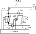
- FIG. 1 is a block diagram illustrating a configuration example of the power supply device 1 according to the embodiment.
- the power supply device 1 is a high-voltage power supply device that is mounted on a vehicle such as an electric vehicle (EV) and supplies electric power to a high-voltage load section (for example, an inverter) provided in the vehicle.
- a high-voltage load section for example, an inverter
- the power supply device 1 includes battery units 10, a current detector 20, voltage detectors 30A and 30B, switching section 40, and a controller 50.
- the battery units 10 are connected to an external quick charger (external charger) CG and store electric power supplied from the quick charger CG.
- the battery units 10 supply the stored electric power to a high-voltage load section such as an inverter.
- the battery units 10 include a battery 10A as a first battery and a battery 10B as a second battery.
- the battery 10A is a storage battery that is chargeable and dischargeable with direct current electric power, and includes a plurality of battery cells.
- the respective battery cells are formed of secondary batteries that are chargeable and dischargeable, and are formed of, for example, lithium ion batteries.
- the respective battery cells are connected in series with adjacent battery cells.
- the battery 10A stores therein the electric power supplied from the quick charger CG, and supplies the stored electric power to a high-voltage load section such as an inverter.
- the battery 10B is formed in the same manner as the battery 10A. That is, the battery 10B is a storage battery that is chargeable and dischargeable with direct current electric power, and includes a plurality of battery cells.
- the respective battery cells are formed of secondary batteries that are chargeable and dischargeable, and are formed of, for example, lithium ion batteries.
- the respective battery cells are connected in series with adjacent battery cells.
- the battery 10B stores therein the electric power supplied from the quick charger CG, and supplies the stored electric power to a high-voltage load section such as an inverter.
- the current detector 20 detects a current.
- the current detector 20 is provided between the quick charger CG and the battery units 10, and detects a current of the electric power supplied from the quick charger CG to the battery units 10.
- the current detector 20 detects, for example, a current IA of the electric power supplied from the quick charger CG to the battery 10A.
- the current detector 20 detects a current IB of the electric power supplied from the quick charger CG to the battery 10B.
- the current detector 20 is connected to the controller 50 and outputs the detected currents IA and IB to the controller 50.
- the voltage detector 30A detects a voltage.
- the voltage detector 30A is connected in parallel with the battery 10A and detects a voltage between a positive electrode and negative electrode of the battery 10A.
- the voltage detector 30A is connected to the controller 50 and outputs a detected voltage VA of the battery 10A to the controller 50.
- the voltage detector 30B detects a voltage.
- the voltage detector 30B is connected in parallel with the battery 10B and detects a voltage between a positive electrode and negative electrode of the battery 10B.
- the voltage detector 30B is connected to the controller 50 and outputs a detected voltage VB of the battery 10B to the controller 50.
- the switching section 40 switch a connection between the battery 10A and the battery 10B.
- the switching section 40 switch the connection between the battery 10A and the battery 10B to a series connection or a parallel connection based on, for example, a switching signal output from the controller 50.
- the switching section 40 include a switch SW_A, a switch SW_B, and a switch SW_C.
- switches SW_A to SW_C for example, a semiconductor relay, a mechanical relay, or the like may be used, but any switch may be used as far as the switch can allow or shut off the electric power to pass through a current path.
- the switch SW_A is a switch that allows or shuts off the electric power to pass through the current path and that connects the battery 10A and the battery 10B in parallel.
- the switch SW_A is provided between a node P1 and the negative electrode of the battery 10A.
- the node P1 is a node through which a negative electrode of the quick charger CG is connected to a connection wire connecting the negative electrodes of the batteries 10A and 10B.
- the switch SW_B is a switch that allows or shuts off the electric power to pass through the current path and that connects the battery 10A and the battery 10B in parallel.
- the switch SW_B is provided between a node P2 and the positive electrode of the battery 10B.
- the node P2 is a node through which a positive electrode of the quick charger CG is connected to a connection wire connecting the positive electrodes of the respective batteries 10A and 10B.
- the switch SW C is a switch that allows or shuts off the electric power to pass through the current path and that connects the battery 10A and the battery 10B in series.
- the switch SW_C is provided between the negative electrode of the battery 10A and the positive electrode of the battery 10B. By turning the switch SW_C on, the negative electrode of the battery 10A and the positive electrode of the battery 10B are electrically connected to each other, and by turning the switch SW_C off, the negative electrode of the battery 10A and the positive electrode of the battery 10B are electrically shut off from each other.
- the switching section 40 In the switching section 40 formed as described above, by turning the switches SW_A and SW_B on and turning the switch SW C off based on the switching signal from the controller 50, the connection between the battery 10A and the battery 10B is switched to the parallel connection. In addition, in the switching section 40, by turning the switch SW_C on and turning the switches SW_A and SW_B off, the connection between the battery 10A and the battery 10B is switched to the series connection. Furthermore, the switching section 40, by turning the switch SW_A on and turning the switches SW_B and SW_C off, separately connect the battery 10A to the quick charger CG without connecting the battery 10B to the quick charger CG. Furthermore, the switching section 40, by turning the switch SW B on and turning the switches SW_A and SW_C off, separately connect the battery 10B to the quick charger CG without connecting the battery 10A to the quick charger CG.
- the controller 50 controls the switching section 40.
- the controller 50 includes an electronic circuit with a well-known microcomputer as a main component, the microcomputer including CPU, ROM and RAM constituting a storage section, and an interface.
- the controller 50 outputs the switching signal to the switching section 40, so that the connection between the batteries 10A and 10B is switched to the series connection or the parallel connection.
- the controller 50 switches the connection between the batteries 10A and 10B to the series connection, so that the electric power with a high-voltage (for example, about 1000 V) is supplied to the load section.
- the controller 50 switches the connection between the batteries 10A and 10B to the series connection or the parallel connection according to a charging voltage of the electric power supplied from the quick charger CG.
- the controller 50 switches the connection between the batteries 10A and 10B to the series connection to charge the batteries 10A and 10B connected in series with the high-voltage (for example, about 1000V) electric power supplied from the quick charger CG.
- the controller 50 switches the connection between the batteries 10A and 10B to the parallel connection to charge the batteries 10A and 10B connected in parallel with the low-voltage (for example, about 500 V) electric power supplied from the quick charger CG.
- the controller 50 executes a process for equalizing the voltages of the batteries 10A and 10B.
- the controller 50 calculates, for example, a potential difference between the voltage VA of the battery 10A detected by the voltage detector 30A and the voltage VB of the battery 10B detected by the voltage detector 30B.
- the controller 50 switches the connection between the batteries 10A and 10B to the parallel connection to charge the batteries 10A and 10B.
- the controller 50 does not switch the connection between the batteries 10A and 10B to the parallel connection, and executes first the process for equalizing the voltages of the batteries 10A and 10B. For example, as this equalization process, the controller 50 does not charge one battery having a larger voltage out of the battery 10A and the battery 10B, and separately charges the other battery having a smaller voltage. For example, when the voltage VA of the battery 10A is smaller than the voltage VB of the battery 10B, the controller 50 separately connects the battery 10A to the quick charger CG to charge the battery 10A without connecting the battery 10B to the quick charger CG. In contrast, when the voltage VB of the battery 10B is smaller than the voltage VA of the battery 10A, the controller 50 separately connects the battery 10B to the quick charger CG to charge the battery 10B without connecting the battery 10A to the quick charger CG.
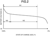
- FIG. 2 is a diagram illustrating a relation between a battery voltage and a state of charge (SOC) according to the embodiment.
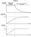
- FIG. 3 is a diagram illustrating an example of quick charging according to the embodiment.
- FIG. 4 is a diagram illustrating a relation between a voltage increase and a time according to the embodiment.
- a usable range W1 of each of the batteries 10A and 10B is determined based on the state of charge.
- the usable range W1 is generally in a range of about 30% to 100% of the state of charge in each of the batteries 10A and 10B.
- the batteries 10A and 10B are each charged with constant current electric power in a range W2 (the state of charge is about 30% to 80%), which is a part of the usable range W1, and is charged with constant voltage electric power in a remaining range W3 (the state of charge is about 80% to 100%) .
- the batteries 10A and 10B are each charged with the constant current electric power until the battery voltage reaches an upper limit voltage Vmax (the state of charge is about 80%) at a time T1, and after the battery voltage reaches the upper limit voltage Vmax at the time T1, the batteries 10A and 10B are each charged with the constant voltage electric power to reduce a charging current. While the batteries 10A and 10B are each being charged with the constant voltage electric power, the charging current gradually decreases to be fully charged (the state of charge is 100%).
- the state of charge in each of the batteries 10A and 10B increases in proportion to time in a case where the batteries 10A and 10B are charged with the constant current electric power.
- the battery voltage of each of the batteries 10A and 10B also increases in proportion to time in the case where the batteries 10A and 10B are charged with the constant current electric power.
- the battery voltage increases in proportion to time as described above. For example, as illustrated in FIG.
- a battery voltage Vt in a case of charging with the constant current electric power during a charging time t can be calculated (see Expression (1) below). That is, it can be known that how much time the battery takes to be charged in order to eliminate the potential difference between the battery 10A and the battery 10B, from the proportional relation between the battery voltage and the charging time.
- Vt V1 ⁇ V0 / t1 ⁇ t0 ⁇ t + V0
- FIG. 5 is a timing chart illustrating the voltage equalization process according to the embodiment.
- the controller 50 switches the connection between the batteries 10A and 10B to the series connection. Therefore, in a case of charging by the parallel connection, the switch SW_C is firstly turned off. In this case, the switches SW_A and SW_B are also turned off.
- the controller 50 firstly detects an initial voltage VA0 of the battery 10A by the voltage detector 30A, and detects an initial voltage VB0 of the battery 10B by the voltage detector 30B.
- the controller 50 turns the switch SW_A on to separately connect the battery 10A to the quick charger CG without connecting the battery 10B to the quick charger CG.
- the controller 50 supplies the constant current electric power from the quick charger CG to the battery 10A for a certain period of time. In this case, the current IA equivalent to a maximum current Imax of the quick charger CG flows through the battery 10A.
- the controller 50 turns the switch SW_A off at a time T2 after the certain period of time has elapsed, and detects the voltage VA1 of the battery 10A by the voltage detector 30A.
- the controller 50 turns the switch SW_B on to separately connect the battery 10B to the quick charger CG without connecting the battery 10A to the quick charger CG. Then, the controller 50 supplies the constant current electric power from the quick charger CG to the battery 10B for a certain period of time. In this case, the current IB equivalent to a maximum current Imax of the quick charger CG flows through the battery 10B.
- the controller 50 turns the switch SW_B off at a time T3 after the certain period of time has elapsed, and detects the voltage VB1 of the battery 10B by the voltage detector 30B.
- the controller 50 calculates an actual voltage increase in the battery 10A per unit time in the certain period of time based on the voltage VA1 of the battery 10A detected by the voltage detector 30A. In addition, the controller 50 calculates an actual voltage increase in the battery 10B per unit time in the certain period of time based on the voltage VB1 of the battery 10B detected by the voltage detector 30B.
- the controller 50 turns the switches SW_A and SW_B on to switch the connection between the respective batteries 10A and 10B to the parallel connection, so that the batteries 10A and 10B are charged.
- the controller 50 calculates the charging time based on the actual voltage increase in the battery 10B per unit time and the potential difference.
- the controller 50 calculates that the charging time is one second. Then, the controller 50 separately charges the battery 10B between a time T4 and a time T5 based on the calculated charging time. In a case where the potential difference between the voltage VA1 of the battery 10A and the voltage VB2 of the battery 10B is lower than the threshold value after charging the battery 10B, the controller 50 turns the switches SW_A and SW_B on at a time T6 to switch the connection between the respective batteries 10A and 10B to the parallel connection, so that the batteries 10A and 10B are charged. In this case, a charging current Ia flowing through the batteries 10A and 10B connected in parallel is about half of the maximum current Imax of the quick charger CG.
- FIG. 6 is a flowchart illustrating the operation example of the power supply device 1 according to the embodiment.
- the controller 50 firstly turns the switches SW_A, SW_B, and SW_C off (step S1).
- the controller 50 detects an initial voltage of the battery 10A by the voltage detector 30A, and detects an initial voltage of the battery 10B by the voltage detector 30B (step S2).
- the controller 50 turns the switch SW_A on to separately connect the battery 10A to the quick charger CG without connecting the battery 10B to the quick charger CG (step S3).
- the controller 50 supplies the constant current electric power from the quick charger CG to the battery 10A for a certain period of time, and detects the voltage VA of the battery 10A by the voltage detector 30A (step S4).
- the controller 50 turns the switch SW_B on to separately connect the battery 10B to the quick charger CG without connecting the battery 10A to the quick charger CG (step S5).
- the controller 50 supplies the constant current electric power from the quick charger CG to the battery 10B for a certain period of time, and detects the voltage VB of the battery 10B by the voltage detector 30B (step S6).
- the controller 50 determines whether the potential difference between the voltage VA of the battery 10A and the voltage VB of the battery 10B is lower than the threshold value (step S7). In a case where the potential difference between the voltage VA of the battery 10A and the voltage VB of the battery 10B is lower than the threshold value (Yes at step S7), the controller 50 turns the switches SW_A and SW_B on to switch the connection between the respective batteries 10A and 10B to the parallel connection, so that the batteries 10A and 10B are charged (step S8). Then, in a case where the state of charge of each of the batteries 10A and 10B reaches 100% and the parallel charging is ended, the controller 50 turns the switches SW A and SW B off to end the parallel charging (step S9).
- the controller 50 calculates the charging time of the battery 10A (step S11).
- the controller 50 calculates the charging time based on, for example, the actual voltage increase in the battery 10A per unit time and the potential difference.
- the controller 50 turns the switch SW_A on during the calculated charging time, so as to separately connect the battery 10A to the quick charger CG and to supply the constant current electric power from the quick charger CG to the battery 10A for a certain period of time, so that the battery 10A is charged (step S12).
- the controller 50 detects the voltage VA of the battery 10A by the voltage detector 30A (step S13), and determines whether the potential difference between the voltage VA of the battery 10A after charging and the voltage VB of the battery 10B is lower than the threshold value after returning to step S7.
- the controller 50 calculates the charging time of the battery 10B (step S14).
- the controller 50 calculates the charging time based on, for example, the actual voltage increase in the battery 10B per unit time and the potential difference.
- the controller 50 turns the switch SW_B on during the calculated charging time, so as to separately connect the battery 10B to the quick charger CG and to supply the constant current electric power from the quick charger CG to the battery 10B for a certain period of time, so that the battery 10B is charged (step S15).
- the controller 50 detects the voltage VB of the battery 10B by the voltage detector 30B (step S16), and determines whether the potential difference between the voltage VA of the battery 10A and the voltage VB of the battery 10B after charging is lower than the threshold value after returning to step S7.
- the power supply device 1 includes the battery 10A and the battery 10B that is chargeable and dischargeable with the electric power, the voltage detector 30A that detects the voltage VA of the battery 10A, the voltage detector 30B that detects the voltage VB of the battery 10B, the switching section 40 that switch the connection between the battery 10A and the battery 10B to the series connection or the parallel connection, and the controller 50 that controls the switching section 40.
- the controller 50 does not switch the connection between the battery 10A and the battery 10B to the parallel connection, does not charge one battery having a larger voltage out of the battery 10A and the battery 10B, and separately charges the other battery having a smaller voltage when the potential difference between the voltage VA of the battery 10A detected by the voltage detector 30A and the voltage VB of the battery 10B detected by the voltage detector 30B is the predetermined threshold value or higher; and the controller 50 switches the connection between the battery 10A and the battery 10B to the parallel connection to charge the battery 10A and the battery 10B when the potential difference is lower than the threshold value.
- the power supply device 1 can switch the connection between the batteries 10A and 10B to the series connection, so that the batteries 10A and 10B are chargeable in series.
- the controller 50 can switch the connection between the batteries 10A and 10B to the parallel connection, so that the batteries 10A and 10B are chargeable in parallel. That is, the power supply device 1 can correspond to the quick charger CG having a specification with a different charging voltage.
- the power supply device 1 equalizes the voltages of the respective batteries 10A and 10B by charging and then connects the batteries 10A and 10B in parallel, the excessive inrush current can be prevented from flowing between the batteries 10A and 10B due to the potential difference. As a result, the power supply device 1 can properly charge the batteries 10A and 10B the connection of which can be switched between the series connection and the parallel connection. Since the power supply device 1 separately charges one battery having a smaller voltage in the voltage equalization process, the voltage equalization process can be performed without wasting energy compared with the conventional control through which the battery is discharged to perform voltage equalization. Since the power supply device 1 does not perform an adjustment by discharging during the voltage equalization process, it is possible to suppress an increase in the charging time. In the power supply device 1, it is possible to reduce parts such as a discharge resistor and a switch that are required for performing the voltage equalization by discharging a battery as in the related art, thereby making it possible to suppress an increase in the number of parts.
- the controller 50 controls the switching section 40 to connect the external charger CG to the battery 10A and to supply the constant current electric power from the external charger CG to the battery 10A for a certain period of time, and controls the switching section 40 to connect the external charger CG to the battery 10B and to supply the constant current electric power from the external charger CG to the battery 10B for a certain period of time.
- the voltage detector 30A detects the voltage VA of the battery 10A in a case where the constant current electric power is supplied from the external charger CG to the battery 10A.
- the voltage detector 30B detects the voltage VB of the battery 10B in a case where the constant current electric power is supplied from the external charger CG to the battery 10B.
- the controller 50 calculates the actual voltage increase in the battery 10A per unit time in the certain period of time based on the voltage VA of the battery 10A detected by the voltage detector 30A. In addition, the controller 50 calculates the actual voltage increase in the battery 10B per unit time in the certain period of time based on the voltage VB of the battery 10B detected by the voltage detector 30B. In a case where the potential difference between the batteries 10A and 10B is the threshold value or higher and the voltage VA of the battery 10A is smaller than the voltage VB of the battery 10B, the controller 50 calculates the charging time based on the actual voltage increase in the battery 10A per unit time and the potential difference, and charges the battery 10A based on the calculated charging time.
- the controller 50 calculates the charging time based on the actual voltage increase in the battery 10B per unit time and the potential difference, and charges the battery 10B based on the calculated charging time.
- the power supply device 1 since the power supply device 1 can execute the voltage equalization process while charging the batteries with the maximum current Imax of the external charger CG, an increase in the charging time can be suppressed. Since the power supply device 1 charges the batteries 10A and 10B based on the calculated charging time, an increase in the number of times to separately charge the battery having a low-voltage can be suppressed compared with a case of charging based on a predetermined charging time. As a result, the power supply device 1 can properly charge the batteries 10A and 10B the connection of which can be switched between the series connection and the parallel connection.
- FIG. 7 is a block diagram illustrating a configuration example of a power supply device 1A according to the modified example of the embodiment.
- the power supply device 1A according to the modified example is different from the power supply device 1 according to the embodiment in that a common voltage detector 30C detects the voltages VA and VB of the respective batteries 10A and 10B.
- the power supply device 1A includes the battery units 10, the current detector 20, the voltage detector 30C, the switching section 40, the controller 50, a charging relay RY1, and a main relay RY2.
- the charging relay RY1 is provided on a quick charging path, is turned on based on the switching signal output from the controller 50 to allow the current of the electric power supplied from the quick charger CG to the batteries 10A and 10B to pass through the path, and is turned off to shut off the current of the electric power supplied from the quick charger CG to the batteries 10A and 10B.
- the main relay RY2 is provided on a path through which electric power is supplied to an inverter IV, is turned on based on the switching signal output from the controller 50 to allow the current of the electric power supplied from the batteries 10A and 10B to the inverter IV to pass through the path, and is turned off to shut off the current of the electric power supplied from the batteries 10A and 10B to the inverter IV.
- One end of the voltage detector 30C is connected between the charging relay RY1 on a positive electrode side and the node P2, and the other end is connected between the charging relay RY1 on a negative electrode side and the node P1.
- the voltage detector 30C detects the voltage VA of the battery 10A in a state where the switch SW_A is turned on and the switches SW_B and SW_C, the charging relay RY1, and the main relay RY2 are turned off.
- the voltage detector 30C is connected to the controller 50 and outputs the detected voltage VA of the battery 10A to the controller 50.
- the voltage detector 30C detects the voltage VB of the battery 10B in a state where the switch SW B is turned on and the switches SW A and SW_C, the charging relay RY1, and the main relay RY2 are turned off.
- the voltage detector 30C outputs the detected voltage VB of the battery 10B to the controller 50.
- the power supply device 1A since the power supply device 1A according to the modified example detects the voltages VA and VB of the respective batteries 10A and 10B by the common voltage detector 30C, it is possible to prevent a voltage error due to the different voltage detectors from each other and to suppress a decrease in the accuracy of the voltage equalization process.
- the controller 50 inputs the current detected by the current detector 20, but the present invention is not limited thereto, and for example, the controller 50 may input the current value during the quick charging by communication from the quick charger CG.
- the controller 50 inputs the voltages VA and VB detected by the voltage detectors 30A and 30B respectively, but the present invention is not limited thereto, and for example, in a case where the voltages of the respective batteries 10A and 10B can be acquired from a battery management system (BMS) or a cell voltage sensor (CVS), which is provided on each of the batteries 10A and 10B, the voltages of the respective batteries 10A and 10B may be obtained from the BMS or the CVS.
- BMS battery management system
- CVS cell voltage sensor
- the power supply device 1 may include three or more batteries.
- the power supply device when the potential difference between the first battery and the second battery is the threshold value or higher, the connection between the first and second batteries is not switched to the parallel connection, and one battery having a larger voltage out of the first battery and the second battery is not charged and the other battery having a smaller voltage is separately charged; and when the potential difference is lower than the threshold value, the connection between the first and second batteries is switched to the parallel connection to charge the first and second batteries.
- the power supply device can equalize the voltages of the first and second batteries by charging and then connect the first and second batteries in parallel, thereby making it possible to properly charge the batteries the connection of which can be switched between the series connection and the parallel connection.
Landscapes
- Engineering & Computer Science (AREA)
- Power Engineering (AREA)
- Charge And Discharge Circuits For Batteries Or The Like (AREA)
- Secondary Cells (AREA)
Description
- The present invention relates to a power supply device.
- In the related art, as a power supply device, for example, it is disclosed in
Japanese Patent Application Laid-open No. 2018-033263 - In the quick charging device described in
Japanese Patent Application Laid-open No. 2018-033263 -
WO 2019/082776 A1 describes a storage system that enables series or parallel connection of two batteries. Before the batteries are switched to parallel connection, the voltages of the two batteries are compared. In case the voltages differ by more than a predetermined threshold, the battery with the higher voltage is discharged to the battery with the lower voltage via a power converter. - The present invention has been made in view of the above description, and an object of the present invention is to provide a power supply device capable of properly charging batteries the connection of which can be switched between a series connection and a parallel connection.
- In order to achieve the above mentioned object, a power supply device according to
claim 1 is provided, which includes a first battery and a second battery that are electrically chargeable and dischargeable; a voltage detector that detects respective voltages of the first battery and the second battery; a switching section configured to switch a connection between the first battery and the second battery to a series connection or a parallel connection; and a controller configured to control the switching section, wherein in a case where the connection between the first battery and the second battery is switched from the series connection to the parallel connection to charge the first battery and the second battery by an external charger, the controller does not switch the connection between the first battery and the second battery to the parallel connection, does not charge one battery having a larger voltage out of the first battery and the second battery, and separately charges the other battery having a smaller voltage when a potential difference between the voltage of the first battery detected by the voltage detector and the voltage of the second battery detected by the voltage detector is a predetermined threshold value or higher, and the controller switches the connection between the first battery and the second battery to the parallel connection and charges the first battery and the second battery when the potential difference is lower than the threshold value. - In the power supply device, the controller controls the switching section to connect the external charger to the first battery and to supply constant current electric power from the external charger to the first battery for a certain period of time, and controls the switching section to connect the external charger to the second battery and to supply the constant current electric power from the external charger to the second battery for a certain period of time, the voltage detector detects the voltage of the first battery in a case where the constant current electric power is supplied from the external charger to the first battery, and detects the voltage of the second battery in a case where the constant current electric power is supplied from the external charger to the second battery, the controller calculates an actual voltage increase in the first battery per unit time in the certain period of time based on the voltage of the first battery detected by the voltage detector and calculates an actual voltage increase in the second battery per unit time in the certain period of time based on the voltage of the second battery detected by the voltage detector, and in a case where the potential difference is the threshold value or higher, the controller calculates a charging time based on the actual voltage increase in the first battery per unit time and the potential difference and charges the first battery based on the calculated charging time when the voltage of the first battery is smaller than the voltage of the second battery, and the controller calculates a charging time based on the actual voltage increase in the second battery per unit time and the potential difference and charges the second battery based on the calculated charging time when the voltage of the second battery is smaller than the voltage of the first battery.
- The above and other objects, features, advantages and technical and industrial significance of this invention will be better understood by reading the following detailed description of presently preferred embodiments of the invention, when considered in connection with the accompanying drawings.
-
-
FIG. 1 is a block diagram illustrating a configuration example of a power supply device according to an embodiment; -
FIG. 2 is a diagram illustrating a relation between a battery voltage and a state of charge (SOC) according to the embodiment; -
FIG. 3 is a diagram illustrating an example of quick charging according to the embodiment; -
FIG. 4 is a diagram illustrating a relation between a voltage increase and a time according to the embodiment; -
FIG. 5 is a timing chart illustrating a voltage equalization process according to the embodiment; -
FIG. 6 is a flowchart illustrating an operation example of the power supply device according to the embodiment; and -
FIG. 7 is a block diagram illustrating a configuration example of a power supply device according to a modified example of the embodiment. - A mode for carrying out the present invention (an embodiment) will be described in detail with reference to the drawings. The present invention is not limited to the contents described in the following embodiment. In addition, the components described below include components that can be easily thought of by those skilled in the art and that are substantially the same. Furthermore, the configurations described below can be combined as appropriate. However, the scope of the invention is solely defined by the appended claim.
- A
power supply device 1 according to an embodiment will be described with reference to the drawings.FIG. 1 is a block diagram illustrating a configuration example of thepower supply device 1 according to the embodiment. Thepower supply device 1 is a high-voltage power supply device that is mounted on a vehicle such as an electric vehicle (EV) and supplies electric power to a high-voltage load section (for example, an inverter) provided in the vehicle. Hereinafter, thepower supply device 1 will be described in detail. - As illustrated in
FIG. 1 , thepower supply device 1 includesbattery units 10, acurrent detector 20,voltage detectors switching section 40, and acontroller 50. - The
battery units 10 are connected to an external quick charger (external charger) CG and store electric power supplied from the quick charger CG. Thebattery units 10 supply the stored electric power to a high-voltage load section such as an inverter. Thebattery units 10 include abattery 10A as a first battery and abattery 10B as a second battery. - The
battery 10A is a storage battery that is chargeable and dischargeable with direct current electric power, and includes a plurality of battery cells. The respective battery cells are formed of secondary batteries that are chargeable and dischargeable, and are formed of, for example, lithium ion batteries. The respective battery cells are connected in series with adjacent battery cells. Thebattery 10A stores therein the electric power supplied from the quick charger CG, and supplies the stored electric power to a high-voltage load section such as an inverter. - The
battery 10B is formed in the same manner as thebattery 10A. That is, thebattery 10B is a storage battery that is chargeable and dischargeable with direct current electric power, and includes a plurality of battery cells. The respective battery cells are formed of secondary batteries that are chargeable and dischargeable, and are formed of, for example, lithium ion batteries. The respective battery cells are connected in series with adjacent battery cells. Thebattery 10B stores therein the electric power supplied from the quick charger CG, and supplies the stored electric power to a high-voltage load section such as an inverter. - The
current detector 20 detects a current. Thecurrent detector 20 is provided between the quick charger CG and thebattery units 10, and detects a current of the electric power supplied from the quick charger CG to thebattery units 10. Thecurrent detector 20 detects, for example, a current IA of the electric power supplied from the quick charger CG to thebattery 10A. In addition, thecurrent detector 20 detects a current IB of the electric power supplied from the quick charger CG to thebattery 10B. Thecurrent detector 20 is connected to thecontroller 50 and outputs the detected currents IA and IB to thecontroller 50. - The
voltage detector 30A detects a voltage. Thevoltage detector 30A is connected in parallel with thebattery 10A and detects a voltage between a positive electrode and negative electrode of thebattery 10A. Thevoltage detector 30A is connected to thecontroller 50 and outputs a detected voltage VA of thebattery 10A to thecontroller 50. - The
voltage detector 30B detects a voltage. Thevoltage detector 30B is connected in parallel with thebattery 10B and detects a voltage between a positive electrode and negative electrode of thebattery 10B. Thevoltage detector 30B is connected to thecontroller 50 and outputs a detected voltage VB of thebattery 10B to thecontroller 50. - The
switching section 40 switch a connection between thebattery 10A and thebattery 10B. Theswitching section 40 switch the connection between thebattery 10A and thebattery 10B to a series connection or a parallel connection based on, for example, a switching signal output from thecontroller 50. Theswitching section 40 include a switch SW_A, a switch SW_B, and a switch SW_C. As the switches SW_A to SW_C, for example, a semiconductor relay, a mechanical relay, or the like may be used, but any switch may be used as far as the switch can allow or shut off the electric power to pass through a current path. - The switch SW_A is a switch that allows or shuts off the electric power to pass through the current path and that connects the
battery 10A and thebattery 10B in parallel. The switch SW_A is provided between a node P1 and the negative electrode of thebattery 10A. Here, the node P1 is a node through which a negative electrode of the quick charger CG is connected to a connection wire connecting the negative electrodes of thebatteries battery 10A and the negative electrode of thebattery 10B are electrically connected to each other, and the negative electrode of thebattery 10A and the negative electrode of the quick charger CG are electrically connected to each other. By turning the switch SW_A off, the negative electrode of thebattery 10A and the negative electrode of thebattery 10B are electrically shut off from each other, and the negative electrode of thebattery 10A and the negative electrode of the quick charger CG are electrically shut off from each other. - The switch SW_B is a switch that allows or shuts off the electric power to pass through the current path and that connects the
battery 10A and thebattery 10B in parallel. The switch SW_B is provided between a node P2 and the positive electrode of thebattery 10B. Here, the node P2 is a node through which a positive electrode of the quick charger CG is connected to a connection wire connecting the positive electrodes of therespective batteries battery 10A and the positive electrode of thebattery 10B are electrically connected to each other, and the positive electrode of thebattery 10B and the positive electrode of the quick charger CG are electrically connected to each other. By turning the switch SW_B off, the positive electrode of thebattery 10A and the positive electrode of thebattery 10B are electrically shut off from each other, and the positive electrode of thebattery 10B and the positive electrode of the quick charger CG are electrically shut off from each other. - The switch SW C is a switch that allows or shuts off the electric power to pass through the current path and that connects the
battery 10A and thebattery 10B in series. The switch SW_C is provided between the negative electrode of thebattery 10A and the positive electrode of thebattery 10B. By turning the switch SW_C on, the negative electrode of thebattery 10A and the positive electrode of thebattery 10B are electrically connected to each other, and by turning the switch SW_C off, the negative electrode of thebattery 10A and the positive electrode of thebattery 10B are electrically shut off from each other. - In the
switching section 40 formed as described above, by turning the switches SW_A and SW_B on and turning the switch SW C off based on the switching signal from thecontroller 50, the connection between thebattery 10A and thebattery 10B is switched to the parallel connection. In addition, in theswitching section 40, by turning the switch SW_C on and turning the switches SW_A and SW_B off, the connection between thebattery 10A and thebattery 10B is switched to the series connection. Furthermore, the switchingsection 40, by turning the switch SW_A on and turning the switches SW_B and SW_C off, separately connect thebattery 10A to the quick charger CG without connecting thebattery 10B to the quick charger CG. Furthermore, the switchingsection 40, by turning the switch SW B on and turning the switches SW_A and SW_C off, separately connect thebattery 10B to the quick charger CG without connecting thebattery 10A to the quick charger CG. - The
controller 50 controls theswitching section 40. Thecontroller 50 includes an electronic circuit with a well-known microcomputer as a main component, the microcomputer including CPU, ROM and RAM constituting a storage section, and an interface. Thecontroller 50 outputs the switching signal to theswitching section 40, so that the connection between thebatteries - For example, in a case where the electric power is supplied to a load section (for example, an inverter) from the
batteries controller 50 switches the connection between thebatteries batteries controller 50 switches the connection between thebatteries controller 50 switches the connection between thebatteries batteries controller 50 switches the connection between thebatteries batteries - In a case where the electric power is supplied to the load section by the
batteries batteries batteries controller 50 executes a process for equalizing the voltages of thebatteries controller 50 calculates, for example, a potential difference between the voltage VA of thebattery 10A detected by thevoltage detector 30A and the voltage VB of thebattery 10B detected by thevoltage detector 30B. Then, in a case where the calculated potential difference is compared with a predetermined threshold value, and the potential difference is lower than the threshold value, an excessive inrush current does not flow between thebatteries controller 50 switches the connection between thebatteries batteries - In contrast, when the potential difference is the threshold value or higher, the excessive inrush current flows between the
batteries controller 50 does not switch the connection between thebatteries batteries controller 50 does not charge one battery having a larger voltage out of thebattery 10A and thebattery 10B, and separately charges the other battery having a smaller voltage. For example, when the voltage VA of thebattery 10A is smaller than the voltage VB of thebattery 10B, thecontroller 50 separately connects thebattery 10A to the quick charger CG to charge thebattery 10A without connecting thebattery 10B to the quick charger CG. In contrast, when the voltage VB of thebattery 10B is smaller than the voltage VA of thebattery 10A, thecontroller 50 separately connects thebattery 10B to the quick charger CG to charge thebattery 10B without connecting thebattery 10A to the quick charger CG. - Next, the equalization process will be described in detail.
FIG. 2 is a diagram illustrating a relation between a battery voltage and a state of charge (SOC) according to the embodiment.FIG. 3 is a diagram illustrating an example of quick charging according to the embodiment.FIG. 4 is a diagram illustrating a relation between a voltage increase and a time according to the embodiment. As illustrated inFIG. 2 , in thebatteries batteries batteries batteries - In the quick charging by the quick charger CG as illustrated in
FIG. 3 , for example, thebatteries batteries batteries - As illustrated in
FIG. 3 , the state of charge in each of thebatteries batteries batteries batteries FIG. 4 , in a case where an initial voltage V0, an initial voltage time t0, a charging end time t1, and a voltage V1 at the charging end time t1 are known, a battery voltage Vt in a case of charging with the constant current electric power during a charging time t can be calculated (see Expression (1) below). That is, it can be known that how much time the battery takes to be charged in order to eliminate the potential difference between thebattery 10A and thebattery 10B, from the proportional relation between the battery voltage and the charging time.
- Next, an actual voltage equalization process will be described in detail.
FIG. 5 is a timing chart illustrating the voltage equalization process according to the embodiment. In a case where the electric power is supplied to a load section (for example, an inverter) from each of thebatteries controller 50 switches the connection between thebatteries - At the time T1 illustrated in
FIG. 5 , thecontroller 50 firstly detects an initial voltage VA0 of thebattery 10A by thevoltage detector 30A, and detects an initial voltage VB0 of thebattery 10B by thevoltage detector 30B. Next, thecontroller 50 turns the switch SW_A on to separately connect thebattery 10A to the quick charger CG without connecting thebattery 10B to the quick charger CG. Then, thecontroller 50 supplies the constant current electric power from the quick charger CG to thebattery 10A for a certain period of time. In this case, the current IA equivalent to a maximum current Imax of the quick charger CG flows through thebattery 10A. Thecontroller 50 turns the switch SW_A off at a time T2 after the certain period of time has elapsed, and detects the voltage VA1 of thebattery 10A by thevoltage detector 30A. - Next, the
controller 50 turns the switch SW_B on to separately connect thebattery 10B to the quick charger CG without connecting thebattery 10A to the quick charger CG. Then, thecontroller 50 supplies the constant current electric power from the quick charger CG to thebattery 10B for a certain period of time. In this case, the current IB equivalent to a maximum current Imax of the quick charger CG flows through thebattery 10B. Thecontroller 50 turns the switch SW_B off at a time T3 after the certain period of time has elapsed, and detects the voltage VB1 of thebattery 10B by thevoltage detector 30B. - The
controller 50 calculates an actual voltage increase in thebattery 10A per unit time in the certain period of time based on the voltage VA1 of thebattery 10A detected by thevoltage detector 30A. In addition, thecontroller 50 calculates an actual voltage increase in thebattery 10B per unit time in the certain period of time based on the voltage VB1 of thebattery 10B detected by thevoltage detector 30B. - In a case where the potential difference between the voltage VA1 of the
battery 10A and the voltage VB1 of thebattery 10B is lower than the threshold value, thecontroller 50 turns the switches SW_A and SW_B on to switch the connection between therespective batteries batteries battery 10A and the voltage VB1 of thebattery 10B is the threshold value or higher and the voltage VB1 of thebattery 10B is smaller than the voltage VA1 of thebattery 10A, thecontroller 50 calculates the charging time based on the actual voltage increase in thebattery 10B per unit time and the potential difference. For example, in a case where the actual voltage increase per second is 3 V and the potential difference is 3 V, thecontroller 50 calculates that the charging time is one second. Then, thecontroller 50 separately charges thebattery 10B between a time T4 and a time T5 based on the calculated charging time. In a case where the potential difference between the voltage VA1 of thebattery 10A and the voltage VB2 of thebattery 10B is lower than the threshold value after charging thebattery 10B, thecontroller 50 turns the switches SW_A and SW_B on at a time T6 to switch the connection between therespective batteries batteries batteries - Next, an operation example of the
power supply device 1 will be described with reference to the flowchart.FIG. 6 is a flowchart illustrating the operation example of thepower supply device 1 according to the embodiment. In a case where charging is performed by switching the connection between thebatteries controller 50 firstly turns the switches SW_A, SW_B, and SW_C off (step S1). Next, thecontroller 50 detects an initial voltage of thebattery 10A by thevoltage detector 30A, and detects an initial voltage of thebattery 10B by thevoltage detector 30B (step S2). Next, thecontroller 50 turns the switch SW_A on to separately connect thebattery 10A to the quick charger CG without connecting thebattery 10B to the quick charger CG (step S3). Then, thecontroller 50 supplies the constant current electric power from the quick charger CG to thebattery 10A for a certain period of time, and detects the voltage VA of thebattery 10A by thevoltage detector 30A (step S4). Next, thecontroller 50 turns the switch SW_B on to separately connect thebattery 10B to the quick charger CG without connecting thebattery 10A to the quick charger CG (step S5). Then, thecontroller 50 supplies the constant current electric power from the quick charger CG to thebattery 10B for a certain period of time, and detects the voltage VB of thebattery 10B by thevoltage detector 30B (step S6). - The
controller 50 determines whether the potential difference between the voltage VA of thebattery 10A and the voltage VB of thebattery 10B is lower than the threshold value (step S7). In a case where the potential difference between the voltage VA of thebattery 10A and the voltage VB of thebattery 10B is lower than the threshold value (Yes at step S7), thecontroller 50 turns the switches SW_A and SW_B on to switch the connection between therespective batteries batteries batteries controller 50 turns the switches SW A and SW B off to end the parallel charging (step S9). - At step S7 described above, in a case where the potential difference between the voltage VA of the
battery 10A and the voltage VB of thebattery 10B is the threshold value or higher (No at step S7) and the voltage VA of thebattery 10A is smaller than the voltage VB of thebattery 10B (Yes at step S10), thecontroller 50 calculates the charging time of thebattery 10A (step S11). Thecontroller 50 calculates the charging time based on, for example, the actual voltage increase in thebattery 10A per unit time and the potential difference. Then, thecontroller 50 turns the switch SW_A on during the calculated charging time, so as to separately connect thebattery 10A to the quick charger CG and to supply the constant current electric power from the quick charger CG to thebattery 10A for a certain period of time, so that thebattery 10A is charged (step S12). Next, thecontroller 50 detects the voltage VA of thebattery 10A by thevoltage detector 30A (step S13), and determines whether the potential difference between the voltage VA of thebattery 10A after charging and the voltage VB of thebattery 10B is lower than the threshold value after returning to step S7. - At step S10 described above, in a case where the voltage VB of the
battery 10B is smaller than the voltage VA of thebattery 10A (No at step S10), thecontroller 50 calculates the charging time of thebattery 10B (step S14). Thecontroller 50 calculates the charging time based on, for example, the actual voltage increase in thebattery 10B per unit time and the potential difference. Then, thecontroller 50 turns the switch SW_B on during the calculated charging time, so as to separately connect thebattery 10B to the quick charger CG and to supply the constant current electric power from the quick charger CG to thebattery 10B for a certain period of time, so that thebattery 10B is charged (step S15). Next, thecontroller 50 detects the voltage VB of thebattery 10B by thevoltage detector 30B (step S16), and determines whether the potential difference between the voltage VA of thebattery 10A and the voltage VB of thebattery 10B after charging is lower than the threshold value after returning to step S7. - As described above, the
power supply device 1 according to the embodiment includes thebattery 10A and thebattery 10B that is chargeable and dischargeable with the electric power, thevoltage detector 30A that detects the voltage VA of thebattery 10A, thevoltage detector 30B that detects the voltage VB of thebattery 10B, the switchingsection 40 that switch the connection between thebattery 10A and thebattery 10B to the series connection or the parallel connection, and thecontroller 50 that controls theswitching section 40. In a case where the connection between thebattery 10A and thebattery 10B is switched from the series connection to the parallel connection to charge thebattery 10A and thebattery 10B by the external charger CG, thecontroller 50 does not switch the connection between thebattery 10A and thebattery 10B to the parallel connection, does not charge one battery having a larger voltage out of thebattery 10A and thebattery 10B, and separately charges the other battery having a smaller voltage when the potential difference between the voltage VA of thebattery 10A detected by thevoltage detector 30A and the voltage VB of thebattery 10B detected by thevoltage detector 30B is the predetermined threshold value or higher; and thecontroller 50 switches the connection between thebattery 10A and thebattery 10B to the parallel connection to charge thebattery 10A and thebattery 10B when the potential difference is lower than the threshold value. - With this configuration, in a case where the charging voltage of the electric power supplied from the quick charger CG is a relatively high-voltage (for example, about 1000 V), the
power supply device 1 can switch the connection between thebatteries batteries controller 50 can switch the connection between thebatteries batteries power supply device 1 can correspond to the quick charger CG having a specification with a different charging voltage. In this case, since thepower supply device 1 equalizes the voltages of therespective batteries batteries batteries power supply device 1 can properly charge thebatteries power supply device 1 separately charges one battery having a smaller voltage in the voltage equalization process, the voltage equalization process can be performed without wasting energy compared with the conventional control through which the battery is discharged to perform voltage equalization. Since thepower supply device 1 does not perform an adjustment by discharging during the voltage equalization process, it is possible to suppress an increase in the charging time. In thepower supply device 1, it is possible to reduce parts such as a discharge resistor and a switch that are required for performing the voltage equalization by discharging a battery as in the related art, thereby making it possible to suppress an increase in the number of parts. - In the
power supply device 1, thecontroller 50 controls theswitching section 40 to connect the external charger CG to thebattery 10A and to supply the constant current electric power from the external charger CG to thebattery 10A for a certain period of time, and controls theswitching section 40 to connect the external charger CG to thebattery 10B and to supply the constant current electric power from the external charger CG to thebattery 10B for a certain period of time. Thevoltage detector 30A detects the voltage VA of thebattery 10A in a case where the constant current electric power is supplied from the external charger CG to thebattery 10A. Thevoltage detector 30B detects the voltage VB of thebattery 10B in a case where the constant current electric power is supplied from the external charger CG to thebattery 10B. Thecontroller 50 calculates the actual voltage increase in thebattery 10A per unit time in the certain period of time based on the voltage VA of thebattery 10A detected by thevoltage detector 30A. In addition, thecontroller 50 calculates the actual voltage increase in thebattery 10B per unit time in the certain period of time based on the voltage VB of thebattery 10B detected by thevoltage detector 30B. In a case where the potential difference between thebatteries battery 10A is smaller than the voltage VB of thebattery 10B, thecontroller 50 calculates the charging time based on the actual voltage increase in thebattery 10A per unit time and the potential difference, and charges thebattery 10A based on the calculated charging time. In contrast, in a case where the voltage VB of thebattery 10B is smaller than the voltage VA of thebattery 10A, thecontroller 50 calculates the charging time based on the actual voltage increase in thebattery 10B per unit time and the potential difference, and charges thebattery 10B based on the calculated charging time. With this configuration, since thepower supply device 1 can execute the voltage equalization process while charging the batteries with the maximum current Imax of the external charger CG, an increase in the charging time can be suppressed. Since thepower supply device 1 charges thebatteries power supply device 1 can properly charge thebatteries - Next, a modified example of the embodiment will be described. In the modified example, the same components as in the embodiment are denoted by the same reference numerals, and the detailed descriptions thereof will not be repeated.
FIG. 7 is a block diagram illustrating a configuration example of apower supply device 1A according to the modified example of the embodiment. Thepower supply device 1A according to the modified example is different from thepower supply device 1 according to the embodiment in that acommon voltage detector 30C detects the voltages VA and VB of therespective batteries - The
power supply device 1A includes thebattery units 10, thecurrent detector 20, thevoltage detector 30C, the switchingsection 40, thecontroller 50, a charging relay RY1, and a main relay RY2. - The charging relay RY1 is provided on a quick charging path, is turned on based on the switching signal output from the
controller 50 to allow the current of the electric power supplied from the quick charger CG to thebatteries batteries - The main relay RY2 is provided on a path through which electric power is supplied to an inverter IV, is turned on based on the switching signal output from the
controller 50 to allow the current of the electric power supplied from thebatteries batteries - One end of the
voltage detector 30C is connected between the charging relay RY1 on a positive electrode side and the node P2, and the other end is connected between the charging relay RY1 on a negative electrode side and the node P1. Thevoltage detector 30C detects the voltage VA of thebattery 10A in a state where the switch SW_A is turned on and the switches SW_B and SW_C, the charging relay RY1, and the main relay RY2 are turned off. Thevoltage detector 30C is connected to thecontroller 50 and outputs the detected voltage VA of thebattery 10A to thecontroller 50. In addition, thevoltage detector 30C detects the voltage VB of thebattery 10B in a state where the switch SW B is turned on and the switches SW A and SW_C, the charging relay RY1, and the main relay RY2 are turned off. Thevoltage detector 30C outputs the detected voltage VB of thebattery 10B to thecontroller 50. - As described above, since the
power supply device 1A according to the modified example detects the voltages VA and VB of therespective batteries common voltage detector 30C, it is possible to prevent a voltage error due to the different voltage detectors from each other and to suppress a decrease in the accuracy of the voltage equalization process. - In the above description, the example in which the
controller 50 inputs the current detected by thecurrent detector 20, but the present invention is not limited thereto, and for example, thecontroller 50 may input the current value during the quick charging by communication from the quick charger CG. - It is described that the
controller 50 inputs the voltages VA and VB detected by thevoltage detectors respective batteries batteries respective batteries - Although the example in which the
power supply device 1 includes twobatteries power supply device 1 may include three or more batteries. - In the power supply device according to the embodiment, when the potential difference between the first battery and the second battery is the threshold value or higher, the connection between the first and second batteries is not switched to the parallel connection, and one battery having a larger voltage out of the first battery and the second battery is not charged and the other battery having a smaller voltage is separately charged; and when the potential difference is lower than the threshold value, the connection between the first and second batteries is switched to the parallel connection to charge the first and second batteries. With this configuration, the power supply device can equalize the voltages of the first and second batteries by charging and then connect the first and second batteries in parallel, thereby making it possible to properly charge the batteries the connection of which can be switched between the series connection and the parallel connection.
Claims (1)
- A power supply device (1, 1A) comprising:a first battery (10A) and a second battery (10B) that are electrically chargeable anddischargeable;a voltage detector (30A, 30B, 30C) configured to detect respective voltages of the first battery (10A) and the second battery (10B);a switching section (40) configured to switch a connection between the first battery (10A) and the second battery (10B) to a series connection or a parallel connection; anda controller (50) configured to control the switching section (40), whereinin a case where the connection between the first battery (10A) and the second battery (10B) is switched from the series connection to the parallel connection to charge the first battery (10A) and the second battery (10B) by an external charger (CG), prior to switching the connection between the first battery (10A) and the second battery (10B) to the parallel connection, the controller (50) is configured not to charge one battery having a larger voltage out of the first battery (10A) and the second battery (10B), and separately to charge the other battery having a smaller voltage when a potential difference between the voltage (VA) of the first battery (10A) detected by the voltage detector (30A, 30C) and the voltage (VB) of the second battery (10B) detected by the voltage detector (30B, 30C) is a predetermined threshold value or higher, and the controller (50) is configured to switch the connection between the first battery (10A) and the second battery (10B) to the parallel connection and to charge the first battery (10A) and the second battery (10B) when the potential difference is lower than the threshold value;characterized in that:the controller (50) is configured to control the switching section (40) to connect the external charger (CG) to the first battery (10A) and to supply constant current electric power from the external charger (CG) to the first battery (10A) for a certain period of time, and to controlthe switching section (40) to connect the external charger (CG) to the second battery (10B) and to supply the constant current electric power from the external charger (CG) to the second battery (10B) for a certain period of time,the voltage detector (30A, 30B, 30C) is configured to detect the voltage (VA) of the first battery (10A) in a case where the constant current electric power is supplied from the external charger (CG) to the first battery (10A), and to detectthe voltage (VB) of the second battery (10B) in a case where the constant current electric power is supplied from the external charger (CG) to the second battery (10B), the controller (50) is configured to calculate an actual voltage increase in the first battery (10A) per unit time in the certain period of time based on the voltage (VA) of the first battery (10A) detected by the voltage detector (30A, 30C) and to calculate an actual voltage increase in the second battery (10B) per unit time in the certain period of time based on the voltage (VB) of the second battery (10B) detected by the voltage detector (30B, 30C), andin a case where the potential difference is the threshold value or higher, the controller (50) is configured to calculate a charging time based on the actual voltage increase in the first battery (10A) per unit time and the potential difference and charges the first battery (10A) based on the calculated charging time when the voltage (VA) of the first battery (10A) is smaller than the voltage (VB) of the second battery (10B), and the controller (50) is configured to calculate a charging time based on the actual voltage increase in the second battery (10B) per unit time and the potential difference and charges the second battery (10B) based on the calculated charging time when the voltage (VB) of the second battery (10B) is smaller than the voltage (VA) of the first battery (10A).
Applications Claiming Priority (1)
| Application Number | Priority Date | Filing Date | Title |
|---|---|---|---|
| JP2020020385A JP7083858B2 (en) | 2020-02-10 | 2020-02-10 | Power supply |
Publications (2)
| Publication Number | Publication Date |
|---|---|
| EP3863143A1 EP3863143A1 (en) | 2021-08-11 |
| EP3863143B1 true EP3863143B1 (en) | 2022-02-23 |
Family
ID=74561755
Family Applications (1)
| Application Number | Title | Priority Date | Filing Date |
|---|---|---|---|
| EP21155749.1A Active EP3863143B1 (en) | 2020-02-10 | 2021-02-08 | Power supply device |
Country Status (4)
| Country | Link |
|---|---|
| US (1) | US11581747B2 (en) |
| EP (1) | EP3863143B1 (en) |
| JP (1) | JP7083858B2 (en) |
| CN (1) | CN113258632B (en) |
Families Citing this family (7)
| Publication number | Priority date | Publication date | Assignee | Title |
|---|---|---|---|---|
| KR102361334B1 (en) * | 2018-05-09 | 2022-02-09 | 주식회사 엘지에너지솔루션 | Battery control apparatus, and energy storage system including the same |
| KR20220121601A (en) * | 2021-02-25 | 2022-09-01 | 주식회사 엘지에너지솔루션 | A method for balancing modules and a battery system providing the method |
| KR20230064264A (en) * | 2021-11-03 | 2023-05-10 | 엘지전자 주식회사 | Energy Storage System |
| JP7773343B2 (en) * | 2021-11-05 | 2025-11-19 | Fdk株式会社 | Battery bank unit, remaining charge time calculation method, and remaining charge time calculation program |
| JP7578119B2 (en) * | 2022-06-13 | 2024-11-06 | いすゞ自動車株式会社 | Vehicle power supply unit |
| JP7708322B2 (en) | 2022-09-09 | 2025-07-15 | 株式会社デンソー | Power conversion device and program |
| US20260048683A1 (en) * | 2024-08-15 | 2026-02-19 | Tesla, Inc. | Electric vehicle range extender integration |
Family Cites Families (9)
| Publication number | Priority date | Publication date | Assignee | Title |
|---|---|---|---|---|
| JPH07154924A (en) * | 1993-11-26 | 1995-06-16 | Nec Corp | Battery usage method for portable electronic devices |
| JP5386556B2 (en) * | 2011-08-03 | 2014-01-15 | 株式会社日立製作所 | Battery system |
| FR2992929B1 (en) * | 2012-07-06 | 2014-06-20 | Renault Sa | SYSTEM FOR MANAGING THE CHARGE OF A BATTERY AND RECUPERATIVE BRAKING OF A VEHICLE POWERED AT LEAST IN PART BY THE BATTERY AND ASSOCIATED REGULATION METHOD |
| JP2019526834A (en) * | 2016-08-24 | 2019-09-19 | キネストラル・テクノロジーズ・インコーポレイテッドKinestral Technologies,Inc. | Boost circuit for electrochromic devices |
| JP6779708B2 (en) | 2016-08-25 | 2020-11-04 | 矢崎総業株式会社 | Quick charging device |
| KR20180133018A (en) * | 2017-06-02 | 2018-12-13 | 현대자동차주식회사 | Battery system for vehicle and controlling method |
| JP7009915B2 (en) * | 2017-10-27 | 2022-01-26 | 株式会社デンソー | Power storage system |
| JP7073669B2 (en) * | 2017-10-27 | 2022-05-24 | 株式会社デンソー | Power storage system |
| EP3664251B1 (en) * | 2018-12-07 | 2021-03-03 | Yazaki Corporation | Power supply system |
-
2020
- 2020-02-10 JP JP2020020385A patent/JP7083858B2/en active Active
-
2021
- 2021-01-21 US US17/155,060 patent/US11581747B2/en active Active
- 2021-02-08 EP EP21155749.1A patent/EP3863143B1/en active Active
- 2021-02-08 CN CN202110183606.3A patent/CN113258632B/en active Active
Also Published As
| Publication number | Publication date |
|---|---|
| JP2021126027A (en) | 2021-08-30 |
| US11581747B2 (en) | 2023-02-14 |
| JP7083858B2 (en) | 2022-06-13 |
| CN113258632A (en) | 2021-08-13 |
| EP3863143A1 (en) | 2021-08-11 |
| CN113258632B (en) | 2024-02-09 |
| US20210249875A1 (en) | 2021-08-12 |
Similar Documents
| Publication | Publication Date | Title |
|---|---|---|
| EP3863143B1 (en) | Power supply device | |
| US10427547B2 (en) | Quick charging device | |
| US10756548B2 (en) | Quick charging device with switching unit for individual battery module discharging | |
| EP3764508B1 (en) | Power supply device | |
| CN107064668B (en) | Abnormal detector and method for detecting abnormality | |
| JP6725201B2 (en) | Charge leveling device and power supply system | |
| US9705343B2 (en) | Voltage equalizer | |
| US8680814B2 (en) | Battery charger and battery charging method | |
| US11277012B2 (en) | Battery control unit and battery system | |
| US12451705B2 (en) | Method of battery balancing and battery system providing the same | |
| US12034323B2 (en) | Battery control unit and battery system | |
| CN101192757A (en) | Charging system, charging device and battery assembly | |
| US20170225572A1 (en) | Weld detection apparatus and weld detection method | |
| EP3770002B1 (en) | Method for capacitor precharging and capacitance measurement in electric vehicle drive system | |
| JP7337567B2 (en) | power supply | |
| EP4447261A1 (en) | Battery control system and battery control method | |
| JP6380012B2 (en) | Power storage device and method of connecting power storage device | |
| JP2025122229A (en) | METHOD FOR DETECTING DEFECTIVE BATTERY CELLS AND BATTERY MANAGEMENT SYSTEM PROVIDING THE SAME - Patent application | |
| JP2021192571A (en) | Cell balance control device | |
| KR20150002178U (en) | Apparatus for battery cell balancing |
Legal Events
| Date | Code | Title | Description |
|---|---|---|---|
| PUAI | Public reference made under article 153(3) epc to a published international application that has entered the european phase |
Free format text: ORIGINAL CODE: 0009012 |
|
| STAA | Information on the status of an ep patent application or granted ep patent |
Free format text: STATUS: REQUEST FOR EXAMINATION WAS MADE |
|
| 17P | Request for examination filed |
Effective date: 20210208 |
|
| AK | Designated contracting states |
Kind code of ref document: A1 Designated state(s): AL AT BE BG CH CY CZ DE DK EE ES FI FR GB GR HR HU IE IS IT LI LT LU LV MC MK MT NL NO PL PT RO RS SE SI SK SM TR |
|
| RIN1 | Information on inventor provided before grant (corrected) |
Inventor name: SHIGEZANE, YASUYUKI Inventor name: OISHI, EIICHIRO Inventor name: TSUBAKI, KAZUYA Inventor name: SUGIMURA, KAZUO Inventor name: MORIMOTO, MITSUAKI |
|
| RIC1 | Information provided on ipc code assigned before grant |
Ipc: H02J 7/00 20060101AFI20211015BHEP |
|
| GRAP | Despatch of communication of intention to grant a patent |
Free format text: ORIGINAL CODE: EPIDOSNIGR1 |
|
| STAA | Information on the status of an ep patent application or granted ep patent |
Free format text: STATUS: GRANT OF PATENT IS INTENDED |
|
| INTG | Intention to grant announced |
Effective date: 20211203 |
|
| GRAS | Grant fee paid |
Free format text: ORIGINAL CODE: EPIDOSNIGR3 |
|
| GRAA | (expected) grant |
Free format text: ORIGINAL CODE: 0009210 |
|
| STAA | Information on the status of an ep patent application or granted ep patent |
Free format text: STATUS: THE PATENT HAS BEEN GRANTED |
|
| AK | Designated contracting states |
Kind code of ref document: B1 Designated state(s): AL AT BE BG CH CY CZ DE DK EE ES FI FR GB GR HR HU IE IS IT LI LT LU LV MC MK MT NL NO PL PT RO RS SE SI SK SM TR |
|
| REG | Reference to a national code |
Ref country code: GB Ref legal event code: FG4D |
|
| REG | Reference to a national code |
Ref country code: CH Ref legal event code: EP |
|
| REG | Reference to a national code |
Ref country code: DE Ref legal event code: R096 Ref document number: 602021000016 Country of ref document: DE |
|
| REG | Reference to a national code |
Ref country code: AT Ref legal event code: REF Ref document number: 1471189 Country of ref document: AT Kind code of ref document: T Effective date: 20220315 |
|
| REG | Reference to a national code |
Ref country code: IE Ref legal event code: FG4D |
|
| REG | Reference to a national code |
Ref country code: LT Ref legal event code: MG9D |
|
| REG | Reference to a national code |
Ref country code: NL Ref legal event code: MP Effective date: 20220223 |
|
| REG | Reference to a national code |
Ref country code: AT Ref legal event code: MK05 Ref document number: 1471189 Country of ref document: AT Kind code of ref document: T Effective date: 20220223 |
|
| PG25 | Lapsed in a contracting state [announced via postgrant information from national office to epo] |
Ref country code: SE Free format text: LAPSE BECAUSE OF FAILURE TO SUBMIT A TRANSLATION OF THE DESCRIPTION OR TO PAY THE FEE WITHIN THE PRESCRIBED TIME-LIMIT Effective date: 20220223 Ref country code: RS Free format text: LAPSE BECAUSE OF FAILURE TO SUBMIT A TRANSLATION OF THE DESCRIPTION OR TO PAY THE FEE WITHIN THE PRESCRIBED TIME-LIMIT Effective date: 20220223 Ref country code: PT Free format text: LAPSE BECAUSE OF FAILURE TO SUBMIT A TRANSLATION OF THE DESCRIPTION OR TO PAY THE FEE WITHIN THE PRESCRIBED TIME-LIMIT Effective date: 20220623 Ref country code: NO Free format text: LAPSE BECAUSE OF FAILURE TO SUBMIT A TRANSLATION OF THE DESCRIPTION OR TO PAY THE FEE WITHIN THE PRESCRIBED TIME-LIMIT Effective date: 20220523 Ref country code: NL Free format text: LAPSE BECAUSE OF FAILURE TO SUBMIT A TRANSLATION OF THE DESCRIPTION OR TO PAY THE FEE WITHIN THE PRESCRIBED TIME-LIMIT Effective date: 20220223 Ref country code: LT Free format text: LAPSE BECAUSE OF FAILURE TO SUBMIT A TRANSLATION OF THE DESCRIPTION OR TO PAY THE FEE WITHIN THE PRESCRIBED TIME-LIMIT Effective date: 20220223 Ref country code: HR Free format text: LAPSE BECAUSE OF FAILURE TO SUBMIT A TRANSLATION OF THE DESCRIPTION OR TO PAY THE FEE WITHIN THE PRESCRIBED TIME-LIMIT Effective date: 20220223 Ref country code: ES Free format text: LAPSE BECAUSE OF FAILURE TO SUBMIT A TRANSLATION OF THE DESCRIPTION OR TO PAY THE FEE WITHIN THE PRESCRIBED TIME-LIMIT Effective date: 20220223 Ref country code: BG Free format text: LAPSE BECAUSE OF FAILURE TO SUBMIT A TRANSLATION OF THE DESCRIPTION OR TO PAY THE FEE WITHIN THE PRESCRIBED TIME-LIMIT Effective date: 20220523 |
|
| PG25 | Lapsed in a contracting state [announced via postgrant information from national office to epo] |
Ref country code: PL Free format text: LAPSE BECAUSE OF FAILURE TO SUBMIT A TRANSLATION OF THE DESCRIPTION OR TO PAY THE FEE WITHIN THE PRESCRIBED TIME-LIMIT Effective date: 20220223 Ref country code: LV Free format text: LAPSE BECAUSE OF FAILURE TO SUBMIT A TRANSLATION OF THE DESCRIPTION OR TO PAY THE FEE WITHIN THE PRESCRIBED TIME-LIMIT Effective date: 20220223 Ref country code: GR Free format text: LAPSE BECAUSE OF FAILURE TO SUBMIT A TRANSLATION OF THE DESCRIPTION OR TO PAY THE FEE WITHIN THE PRESCRIBED TIME-LIMIT Effective date: 20220524 Ref country code: FI Free format text: LAPSE BECAUSE OF FAILURE TO SUBMIT A TRANSLATION OF THE DESCRIPTION OR TO PAY THE FEE WITHIN THE PRESCRIBED TIME-LIMIT Effective date: 20220223 Ref country code: AT Free format text: LAPSE BECAUSE OF FAILURE TO SUBMIT A TRANSLATION OF THE DESCRIPTION OR TO PAY THE FEE WITHIN THE PRESCRIBED TIME-LIMIT Effective date: 20220223 |
|
| PG25 | Lapsed in a contracting state [announced via postgrant information from national office to epo] |
Ref country code: IS Free format text: LAPSE BECAUSE OF FAILURE TO SUBMIT A TRANSLATION OF THE DESCRIPTION OR TO PAY THE FEE WITHIN THE PRESCRIBED TIME-LIMIT Effective date: 20220623 |
|
| PG25 | Lapsed in a contracting state [announced via postgrant information from national office to epo] |
Ref country code: SM Free format text: LAPSE BECAUSE OF FAILURE TO SUBMIT A TRANSLATION OF THE DESCRIPTION OR TO PAY THE FEE WITHIN THE PRESCRIBED TIME-LIMIT Effective date: 20220223 Ref country code: SK Free format text: LAPSE BECAUSE OF FAILURE TO SUBMIT A TRANSLATION OF THE DESCRIPTION OR TO PAY THE FEE WITHIN THE PRESCRIBED TIME-LIMIT Effective date: 20220223 Ref country code: RO Free format text: LAPSE BECAUSE OF FAILURE TO SUBMIT A TRANSLATION OF THE DESCRIPTION OR TO PAY THE FEE WITHIN THE PRESCRIBED TIME-LIMIT Effective date: 20220223 Ref country code: EE Free format text: LAPSE BECAUSE OF FAILURE TO SUBMIT A TRANSLATION OF THE DESCRIPTION OR TO PAY THE FEE WITHIN THE PRESCRIBED TIME-LIMIT Effective date: 20220223 Ref country code: DK Free format text: LAPSE BECAUSE OF FAILURE TO SUBMIT A TRANSLATION OF THE DESCRIPTION OR TO PAY THE FEE WITHIN THE PRESCRIBED TIME-LIMIT Effective date: 20220223 Ref country code: CZ Free format text: LAPSE BECAUSE OF FAILURE TO SUBMIT A TRANSLATION OF THE DESCRIPTION OR TO PAY THE FEE WITHIN THE PRESCRIBED TIME-LIMIT Effective date: 20220223 |
|
| REG | Reference to a national code |
Ref country code: DE Ref legal event code: R097 Ref document number: 602021000016 Country of ref document: DE |
|
| PG25 | Lapsed in a contracting state [announced via postgrant information from national office to epo] |
Ref country code: AL Free format text: LAPSE BECAUSE OF FAILURE TO SUBMIT A TRANSLATION OF THE DESCRIPTION OR TO PAY THE FEE WITHIN THE PRESCRIBED TIME-LIMIT Effective date: 20220223 |
|
| PLBE | No opposition filed within time limit |
Free format text: ORIGINAL CODE: 0009261 |
|
| STAA | Information on the status of an ep patent application or granted ep patent |
Free format text: STATUS: NO OPPOSITION FILED WITHIN TIME LIMIT |
|
| 26N | No opposition filed |
Effective date: 20221124 |
|
| PG25 | Lapsed in a contracting state [announced via postgrant information from national office to epo] |
Ref country code: IT Free format text: LAPSE BECAUSE OF FAILURE TO SUBMIT A TRANSLATION OF THE DESCRIPTION OR TO PAY THE FEE WITHIN THE PRESCRIBED TIME-LIMIT Effective date: 20220223 |
|
| PG25 | Lapsed in a contracting state [announced via postgrant information from national office to epo] |
Ref country code: MC Free format text: LAPSE BECAUSE OF FAILURE TO SUBMIT A TRANSLATION OF THE DESCRIPTION OR TO PAY THE FEE WITHIN THE PRESCRIBED TIME-LIMIT Effective date: 20220223 |
|
| REG | Reference to a national code |
Ref country code: BE Ref legal event code: MM Effective date: 20230228 |
|
| PG25 | Lapsed in a contracting state [announced via postgrant information from national office to epo] |
Ref country code: LU Free format text: LAPSE BECAUSE OF NON-PAYMENT OF DUE FEES Effective date: 20230208 |
|
| REG | Reference to a national code |
Ref country code: IE Ref legal event code: MM4A |
|
| PG25 | Lapsed in a contracting state [announced via postgrant information from national office to epo] |
Ref country code: IE Free format text: LAPSE BECAUSE OF NON-PAYMENT OF DUE FEES Effective date: 20230208 Ref country code: FR Free format text: LAPSE BECAUSE OF NON-PAYMENT OF DUE FEES Effective date: 20230228 |
|
| PG25 | Lapsed in a contracting state [announced via postgrant information from national office to epo] |
Ref country code: BE Free format text: LAPSE BECAUSE OF NON-PAYMENT OF DUE FEES Effective date: 20230228 |
|
| REG | Reference to a national code |
Ref country code: CH Ref legal event code: PL |
|
| PG25 | Lapsed in a contracting state [announced via postgrant information from national office to epo] |
Ref country code: CH Free format text: LAPSE BECAUSE OF NON-PAYMENT OF DUE FEES Effective date: 20240229 |
|
| PG25 | Lapsed in a contracting state [announced via postgrant information from national office to epo] |
Ref country code: CH Free format text: LAPSE BECAUSE OF NON-PAYMENT OF DUE FEES Effective date: 20240229 |
|
| PG25 | Lapsed in a contracting state [announced via postgrant information from national office to epo] |
Ref country code: CY Free format text: LAPSE BECAUSE OF FAILURE TO SUBMIT A TRANSLATION OF THE DESCRIPTION OR TO PAY THE FEE WITHIN THE PRESCRIBED TIME-LIMIT; INVALID AB INITIO Effective date: 20210208 |
|
| PG25 | Lapsed in a contracting state [announced via postgrant information from national office to epo] |
Ref country code: HU Free format text: LAPSE BECAUSE OF FAILURE TO SUBMIT A TRANSLATION OF THE DESCRIPTION OR TO PAY THE FEE WITHIN THE PRESCRIBED TIME-LIMIT; INVALID AB INITIO Effective date: 20210208 |
|
| GBPC | Gb: european patent ceased through non-payment of renewal fee |
Effective date: 20250208 |
|
| PG25 | Lapsed in a contracting state [announced via postgrant information from national office to epo] |
Ref country code: TR Free format text: LAPSE BECAUSE OF FAILURE TO SUBMIT A TRANSLATION OF THE DESCRIPTION OR TO PAY THE FEE WITHIN THE PRESCRIBED TIME-LIMIT Effective date: 20220223 |
|
| PG25 | Lapsed in a contracting state [announced via postgrant information from national office to epo] |
Ref country code: GB Free format text: LAPSE BECAUSE OF NON-PAYMENT OF DUE FEES Effective date: 20250208 |
|
| PG25 | Lapsed in a contracting state [announced via postgrant information from national office to epo] |
Ref country code: SI Free format text: LAPSE BECAUSE OF FAILURE TO SUBMIT A TRANSLATION OF THE DESCRIPTION OR TO PAY THE FEE WITHIN THE PRESCRIBED TIME-LIMIT Effective date: 20220223 |
|
| PGFP | Annual fee paid to national office [announced via postgrant information from national office to epo] |
Ref country code: DE Payment date: 20251230 Year of fee payment: 6 |