EP3863126A1 - Lever type connector - Google Patents
Lever type connector Download PDFInfo
- Publication number
- EP3863126A1 EP3863126A1 EP21154013.3A EP21154013A EP3863126A1 EP 3863126 A1 EP3863126 A1 EP 3863126A1 EP 21154013 A EP21154013 A EP 21154013A EP 3863126 A1 EP3863126 A1 EP 3863126A1
- Authority
- EP
- European Patent Office
- Prior art keywords
- lever
- connector body
- electric wire
- boss
- connector
- Prior art date
- Legal status (The legal status is an assumption and is not a legal conclusion. Google has not performed a legal analysis and makes no representation as to the accuracy of the status listed.)
- Granted
Links
Images




Classifications
-
- H—ELECTRICITY
- H01—ELECTRIC ELEMENTS
- H01R—ELECTRICALLY-CONDUCTIVE CONNECTIONS; STRUCTURAL ASSOCIATIONS OF A PLURALITY OF MUTUALLY-INSULATED ELECTRICAL CONNECTING ELEMENTS; COUPLING DEVICES; CURRENT COLLECTORS
- H01R13/00—Details of coupling devices of the kinds covered by groups H01R12/70 or H01R24/00 - H01R33/00
- H01R13/62—Means for facilitating engagement or disengagement of coupling parts or for holding them in engagement
- H01R13/629—Additional means for facilitating engagement or disengagement of coupling parts, e.g. aligning or guiding means, levers, gas pressure electrical locking indicators, manufacturing tolerances
- H01R13/62933—Comprising exclusively pivoting lever
- H01R13/62955—Pivoting lever comprising supplementary/additional locking means
-
- H—ELECTRICITY
- H01—ELECTRIC ELEMENTS
- H01R—ELECTRICALLY-CONDUCTIVE CONNECTIONS; STRUCTURAL ASSOCIATIONS OF A PLURALITY OF MUTUALLY-INSULATED ELECTRICAL CONNECTING ELEMENTS; COUPLING DEVICES; CURRENT COLLECTORS
- H01R13/00—Details of coupling devices of the kinds covered by groups H01R12/70 or H01R24/00 - H01R33/00
- H01R13/62—Means for facilitating engagement or disengagement of coupling parts or for holding them in engagement
- H01R13/629—Additional means for facilitating engagement or disengagement of coupling parts, e.g. aligning or guiding means, levers, gas pressure electrical locking indicators, manufacturing tolerances
- H01R13/62933—Comprising exclusively pivoting lever
-
- H—ELECTRICITY
- H01—ELECTRIC ELEMENTS
- H01R—ELECTRICALLY-CONDUCTIVE CONNECTIONS; STRUCTURAL ASSOCIATIONS OF A PLURALITY OF MUTUALLY-INSULATED ELECTRICAL CONNECTING ELEMENTS; COUPLING DEVICES; CURRENT COLLECTORS
- H01R13/00—Details of coupling devices of the kinds covered by groups H01R12/70 or H01R24/00 - H01R33/00
- H01R13/46—Bases; Cases
- H01R13/502—Bases; Cases composed of different pieces
-
- H—ELECTRICITY
- H01—ELECTRIC ELEMENTS
- H01R—ELECTRICALLY-CONDUCTIVE CONNECTIONS; STRUCTURAL ASSOCIATIONS OF A PLURALITY OF MUTUALLY-INSULATED ELECTRICAL CONNECTING ELEMENTS; COUPLING DEVICES; CURRENT COLLECTORS
- H01R13/00—Details of coupling devices of the kinds covered by groups H01R12/70 or H01R24/00 - H01R33/00
- H01R13/56—Means for preventing chafing or fracture of flexible leads at outlet from coupling part
Definitions
- One or more embodiments of the present invention relate to a lever type connector.
- a lever type connector has been known, which assists fitting and detachment relative to a counterpart connector by rotating a lever rotatably provided on a connector body (see, for example, Patent Literatures 1 and 2).
- the lever is formed in a U-shaped cross section including a pair of arm portions and a coupling portion that couples the two arm portions.
- boss portions formed on two outer side faces of the connector body are inserted into boss fitting holes formed in the two arm portions while the pair of arm portions are expanded outward by using elasticity. Therefore, the lever is rotatable.
- One or more embodiments of the present invention have been made in view of the above-described circumstances, and an object thereof is to provide a lever type connector with excellent assembly workability that allows the lever to be easily positioned relative to the connector body.
- a lever type connector including: a connector body including: a pair of side walls; and boss portions protruding from outer surfaces of the pair of side walls, respectively; and a lever having a substantially U-shape and rotatably attachable to the connector body, the lever including: a pair of arm portions having boss fitting holes into which the boss portions are inserted, respectively; and a coupling portion that couples one ends of the pair of arm portions, wherein a fitting force and a detachment force of the connector body relative to a counterpart connector is applied by rotation operation of the lever, wherein an electric wire cover is attached to the connector body, the electric wire cover being configured to cover one or more electric wires drawn out from the connector body, wherein the electric wire cover includes an electric wire lead-out portion having a tubular shape, the electric wire lead-out portion through which the one or more electric wires are allowed to be drawn out together, wherein the coupling portion includes a recessed sliding portion recessed in an arc shape, and where
- One or more embodiments of the present invention can provide a lever type connector having excellent assembly workability, in which a lever can be easily positioned relative to a connector body.
- FIG. 1 is a side view of a lever type connector 1 according to an embodiment of the present invention.
- FIG. 2 is a side view of the lever type connector 1 according to the present embodiment before a lever 20 is attached thereto.
- the lever type connector 1 includes a connector body 10 to be fitted and connected to a counterpart connector 2 described below, and the lever 20 to be attached to the connector body 10.
- An electric wire cover 30 is attached to the connector body 10 in advance.
- the lever 20 is attached to the connector body 10 to which the electric wire cover 30 is attached in an attachment direction A from the rear to the front.
- FIG. 3 is a perspective view of the connector body 10 to which the electric wire cover 30 is attached in advance.
- the connector body 10 is formed in a square tubular shape.
- the connector body 10 includes a terminal accommodating portion 13.
- a plurality of terminal fittings (not illustrated) to which terminals of an electric wire (not illustrated) are crimped and connected are accommodated and held in the terminal accommodating portion 13.
- the connector body 10 includes a pair of side walls 12a, 12b that are vertically disposed to face each other.
- a boss portion 14 for supporting the lever protrudes from an outer surface of each of the side walls 12a, 12b of the connector body 10.
- the boss portion 14 is a shaft that rotatably supports the lever 20.
- the boss portion 14 includes a support shaft portion 14a formed in a cylindrical shape, and a coming-off prevention protrusion 14b protruding laterally from an upper end of the support shaft portion 14a.
- a body-side mark (mark) 17 for visible positioning at the time of attaching the lever 20 to the connector body 10 is provided, at a position in a vicinity of the boss portion 14.
- the body-side mark 17 is provided in a vicinity of an edge portion on an attachment side of the lever 20 of the side wall 12a.
- the body-side mark 17 is formed of an "arrow” indicating a direction, and is arranged along the attachment direction A of the lever 20. The direction of the "arrow" of the body-side mark 17 is directed to the lever 20 side.
- the side walls 12a, 12b of the connector body 10 each are provided with a temporarily locking protrusion 18.
- the temporarily locking protrusion 18 includes a pair of protruding portions 18a, 18b protruding from an outer surface of each of the side walls 12a, 12b, and a locking groove portion 18c between the protruding portions 18a, 18b.
- the electric wire cover 30 is attached to a rear portion of the connector body 10, which is a side opposite to a fitting side with the counterpart connector 2. As a result, in the connector body 10, a rear portion of the terminal accommodating portion 13 is covered by the electric wire cover 30, and a plurality of electric wires (not illustrated) drawn out from the respective terminal accommodating portions 13 are protected.
- the electric wire cover 30 includes a cover body 31 attached to a rear portion of the connector body 10, and a cylindrical electric wire lead-out portion 32 formed on a rear portion of the cover body 31, which is a side opposite to an attachment side to the connector body 10.
- the electric wire lead-out portion 32 is formed on a rear portion of the cover body 31 near an end of the electric wire cover 30 in a width direction.
- a plurality of electric wires (not illustrated) drawn out from the terminal accommodating portion 13 of the connector body 10 are bundled and pass through the electric wire lead-out portion 32.
- the electric wire lead-out portion 32 includes an electric wire lead-out port 32a which is an outlet of the electric wires.
- a plurality of electric wires drawn out from the terminal accommodating portion 13 are guided to the electric wire lead-out portion 32 by the cover body 31 and are bundled, and are drawn out together from the electric wire lead-out port 32a of the electric wire lead-out portion 32.
- the electric wire cover 30 attached to the connector body 10 includes a step portion 35 on the attachment side of the lever 20 to be attached to the connector body 10 in the electric wire lead-out portion 32.
- the step portion 35 is formed at a position in the electric wire lead-out portion 32, which is near the cover body 31.
- an inner diameter of the electric wire lead-out portion 32 of the electric wire cover 30 is increased on the cover body 31 side.
- the electric wire cover 30 is configured such that a plurality of electric wires drawn out from the terminal accommodating portion 13 of the connector body 10 are smoothly guided to the electric wire lead-out portion 32 through a part with an increased diameter, and drawn out from the electric wire lead-out port 32a.
- an end portion side relative to the step portion 35 is defined as a sliding portion 34 having a smooth outer peripheral surface.
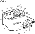
- FIG. 4 is a perspective view of the lever 20 to be attached to the connector body 10.
- FIGS. 5A and 5B illustrate the lever 20 attached to the connector body 10
- FIG. 5A is a front view of the lever 20
- FIG. 5B is a sectional view taken along a line IV-IV in FIG. 5A .
- the lever 20 includes a pair of arm portions 22a, 22b disposed to face each other, and a coupling portion 23 that couples one end side of the arm portion 22a to one end side of the arm portion 22b.
- the lever 20 is formed in a substantially U shape as a whole.
- the coupling portion 23 of the lever 20 serves as an operating portion, and the lever 20 is rotated relative to the connector body 10 by gripping the operating portion.
- the arm portions 22a, 22b of the lever 20 are plate-shaped members that cover the pair of side walls 12a, 12b of the connector body 10, and each include a boss fitting hole 21 into which the boss portion 14 is rotatably fitted.
- the arm portions 22a, 22b respectively cover the outer surfaces of the pair of side walls 12a, 12b from the rear of the connector body 10, and the boss portion 14 is inserted into the boss fitting hole 21.
- the arm portions 22a, 22b are respectively attached to the pair of side walls 12a, 12b so as to be rotatable within a predetermined angle range around an axis of the support shaft portion 14a of the boss portion 14.
- the boss fitting hole 21 includes an inner peripheral protruding ridge 21a, protruding radially inward, at an inner peripheral portion thereof.
- the inner peripheral protruding ridge 21a is formed along a circumferential direction except for a part of the boss fitting hole 21.
- a portion where the inner peripheral protruding ridge 21a is not formed is defined as a protrusion insertion portion 21b.
- the inner peripheral protruding ridge 21a has an inner diameter slightly larger than an outer diameter of the support shaft portion 14a of the boss portion 14, and the protrusion insertion portion 21b has an inner shape slightly larger than an outer shape of the coming-off prevention protrusion 14b of the boss portion 14.
- the arm portions 22a, 22b each have a boss guiding groove 25 connected to the boss fitting hole 21 on an inner surface thereof.
- the boss guiding groove 25 has a width larger than an outer diameter of the boss portion 14.
- the boss guiding groove 25 is formed over an edge portion of each of the arm portions 22a, 22b from the boss fitting hole 21, and a bottom surface thereof is defined as a guiding surface 25a gradually inclined inward from the edge portion of each of the arm portions 22a, 22b toward the boss fitting hole 21 side.
- the arm portion 22a that covers the side wall 12a of the connector body 10 including the body-side mark 17 is provided with, on an outer surface thereof, a lever-side mark (mark) 27 for visible positioning at the time of attaching the lever 20 to the connector body 10.
- the lever-side mark 27 is provided in a vicinity of an edge portion of the arm portion 22a on an attachment side to the connector body 10.
- the lever side mark 27 is formed of an "arrow” indicating a direction, and is arranged along the attachment direction A to the connector body 10. The direction of the "arrow" of the lever-side mark 27 is directed to the connector body 10 side.
- the arm portions 22a, 22b of the lever 20 each have a temporarily locking portion 28.
- the temporarily locking portion 28 includes a pair of slits 28a that penetrate each of the arm portions 22a, 22b, an elastic portion 28b provided by forming the pair of slits 28a, and a locking claw portion 28c formed on the elastic portion 28b.
- the locking claw portions 28c are formed on inner surface sides of the arm portions 22a, 22b, which face each other.
- the elastic portion 28b is elastically deformable relative to the arm portions 22a, 22b in a direction perpendicular to a plane.
- the lever 20 includes a recessed sliding portion 29 on the coupling portion 23.
- the recessed sliding portion 29 is formed on an electric wire lead-out portion 32 side of the electric wire cover 30 when the lever 20 is attached to the connector body 10.
- the recessed sliding portion 29 is formed in a recessed shape recessed in an arc shape.
- the sliding portion 34 of the electric wire lead-out portion 32 formed in an arc shape in a cross-sectional view may be disposed in the recessed sliding portion 29.
- An inner surface of the recessed sliding portion 29 is defined as a tapered surface 29a that is gradually inclined in a direction away from the electric wire lead-out portion 32 toward the attachment direction A (see FIG. 2 ) to the connector body 10 to which the electric wire cover 30 is attached.
- FIGS. 6A and 6B are side views illustrating a procedure of attaching the lever 20 to the connector body 10
- FIG. 6A is a side view of the lever 20 during attachment thereof
- FIG. 6B is a side view of the lever 20 immediately after attachment thereof
- FIG. 7 is a side view of a state in which the lever 20 attached to the connector body 10 is rotated to a temporarily locking position.
- the recessed sliding portion 29 formed on the coupling portion 23 of the lever 20 is positioned relative to the sliding portion 34, which is a part of an outer peripheral portion of the electric wire lead-out portion 32 of the electric wire cover 30, while being brought close to the sliding portion 34. Then, the sliding portion 34 of the electric wire lead-out portion 32 of the electric wire cover 30 enters the recessed sliding portion 29 of the lever 20, and the lever 20 is positioned relative to the connector body 10. As a result, a position of the lever 20 relative to the connector body 10 in a direction perpendicular to the attachment direction A and an attachment angle of the lever 20 relative to the connector body 10 are adjusted.
- the lever 20 is brought close to the connector body 10 in a direction indicated by the lever-side mark 27. Then, the boss portion 14 of the connector body 10 enters the edge portion of the boss guiding groove 25 of the lever 20 and abuts against the guiding surface 25a. In this state, the lever 20 is pushed against the connector body 10. Then, the boss portion 14 is guided in the boss guiding groove 25 while being in sliding contact with the guiding surface 25a, and is moved relatively along the boss guiding groove 25, whereby the arm portions 22a, 22b are pushed outward and elastically deformed.
- the recessed sliding portion 29 of the lever 20 is slid relative to the sliding portion 34 of the electric wire lead-out portion 32 of the electric wire cover 30 that has entered the recessed sliding portion 29.
- the position of the lever 20 relative to the connector body 10 in a direction perpendicular to the attachment direction A and the attachment angle of the lever 20 relative to the connector body 10 are maintained.
- the step portion 35 of the electric wire lead-out portion 32 abuts against the tapered surface 29a of the recessed sliding portion 29 and slides.
- the coupling portion 23 is not caught by the step portion 35 of the electric wire lead-out portion 32, and thus, the lever 20 is smoothly and relatively moved toward the connector body 10.
- the boss portion 14 reaches the boss fitting hole 21 of each of the arm portions 22a, 22b of the lever 20.
- the lever 20 is moved relatively toward the connector body 10 after the lever 20 is positioned relative to the connector body 10 according to the body-side mark 17 and the lever-side mark 27, so that the coming-off prevention protrusion 14b of the boss portion 14 is easily matched with the protrusion insertion portion 21b of the boss fitting hole 21 in a plan view.
- the boss portion 14 when the boss portion 14 reaches the boss fitting hole 21, the elastically deformed arm portions 22a, 22b are restored, and the boss portion 14 including the support shaft portion 14a and the coming-off prevention protrusion 14b is inserted into the boss fitting hole 21 including the inner peripheral protruding ridge 21a and the protrusion insertion portion 21b.
- the coming-off prevention protrusion 14b of the boss portion 14 is disposed outside the inner peripheral protruding ridge 21a of the boss fitting hole 21.
- the lever 20 is rotatably attached to the connector body 10 to which the electric wire cover 30 is attached.
- the lever 20 When the boss portion 14 is inserted into the boss fitting hole 21, the lever 20 is rotated relative to the connector body 10 in one direction (a direction of an arrow X1) as illustrated in FIG. 7 , and the open end of the cam groove 26 is disposed at a temporarily locking position ⁇ directed to the fitting side with the counterpart connector 2 (see FIG. 1 ). Then, the coming-off prevention protrusion 14b formed on the boss portion 14 of each of the arm portions 22a, 22b moves to an outside of the inner peripheral protruding ridge 21a of the boss fitting hole 21, and is locked to the inner peripheral protruding ridge 21a. As a result, the lever 20 is maintained in an attachment state relative to the connector body 10, and detachment of the lever 20 from the connector body 10 due to the application of an external force or the like is prevented.
- FIG. 8 is a perspective view of the counterpart connector 2.
- the counterpart connector 2 to which the lever type connector 1 according to the present embodiment is to be fitted includes a connector body 50 and a flange portion 60.
- the connector body 50 is formed in a square tubular shape having a smaller outer shape than that of the connector body 10 of the lever type connector 1, and includes a terminal accommodating portion 53, which accommodates a plurality of terminal fittings, therein.
- a bolt insertion hole 61 is formed in the flange portion 60, and a bolt (not illustrated) inserted into the bolt insertion hole 61 is screwed into a screw hole formed in an attachment portion (not illustrated) such as a housing, and thereby the counterpart connector 2 is fixed to the attachment portion.
- a pair of wall portions 63a, 63b are formed in the flange portion 60.
- the wall portion 63a, 63b are respectively disposed with gaps between the wall portions 63a, 63b and a pair of side walls 52a, 52b of the connector body 50.
- Cam shafts 64 protruding toward the side walls 52a, 52b are respectively formed on the wall portions 63a, 63b.
- the connector body 50 of the counterpart connector 2 is fitted into the connector body 10 in a state in which the lever 20 is disposed at the temporarily locking position ⁇ . Then, the cam shaft 64 provided on the counterpart connector 2 is inserted into the cam groove 26 from one end side. In this state, the lever 20 is rotated in one direction (a direction of an arrow X2 in FIG. 1 ), and the lever 20 is disposed at the final locking position ⁇ along the connector body 10 (see FIG. 1 ). Then, the cam shaft 64 inserted into one end of the cam groove 26 is relatively guided to the other end of the cam groove 26 that reaches the vicinity of the boss fitting hole 21. As a result, the counterpart connector 2 is pulled and fitted to the connector body 10, and the terminal fittings of the respective terminal accommodating portions 13, 53 are electrically connected to each other.
- an operator attaches the lever 20 to the connector body 10 by positioning the recessed sliding portion 29 of the lever 20 relative to the sliding portion 34, which is a part of the outer peripheral portion of the electric wire lead-out portion 32 of the electric wire cover 30, while bringing the recessed sliding portion 29 close to the sliding portion 34. Then, the recessed sliding portion 29 is slid on the electric wire lead-out portion 32, and the lever 20 is guided to the connector body 10. As a result, the position of the boss fitting hole 21 of the lever 20 is aligned with the position of the boss portion 14 of the connector body 10, and the boss portion 14 is inserted into the boss fitting hole 21, so that the lever 20 can be rotatably attached to the connector body 10.
- the lever 20 can be easily attached to the connector body 10 by being positioned relative to the connector body 10 without using a positioning jig or the like. Accordingly, the attaching workability of the lever 20 relative to the connector body 10 can be improved, and the burden on the operator can be reduced.
- the inner surface of the recessed sliding portion 29 is defined as the tapered surface 29a that is gradually inclined in a direction away from the electric wire lead-out portion 32 toward the attachment direction A of the lever 20 to the connector body 10. Therefore, even if a protruding portion such as the step portion 35 is provided on the outer peripheral portion of the electric wire lead-out portion 32 of the electric wire cover 30, the protruding portion such as the step portion 35 abuts against the tapered surface 29a of the recessed sliding portion 29 and slides when the lever 20 is attached to the connector body 10. Therefore, the protruding portion of the electric wire lead-out portion 32 is not caught by the coupling portion 23 of the lever 20, and thus, the lever 20 can be smoothly and relatively moved toward the connector body 10 and attached to the connector body 10.
- the operator can check a positioning state of the lever 20 relative to the connector body 10 and the attachment direction of the lever 20 to the connector body 10 by visually confirming that the direction indicated by the arrow of the body-side mark 17 of the connector body 10 faces the direction indicated by the arrow of the lever-side mark 27 of the lever 20.
- the attachment workability of the lever 20 relative to the connector body 10 can be further improved, and the burden on the operator can be reduced.
- an operator attaches the lever to the connector body by positioning the lever relative to the connector body while bringing the recessed sliding portion in contact with the part of the outer peripheral portion of the electric wire lead out portion of the electric wire cover. Then, the recessed sliding portion is slid on the electric wire lead-out portion, and the lever is guided to the connector body.
- the positions of the boss fitting holes of the lever are aligned with the positions of the boss portions of the connector body, and the boss portions are inserted into the boss fitting holes, so that the lever can be rotatably attached to the connector body. Therefore, the lever can be easily attached to the connector body by being positioned relative to the connector body without using a positioning jig or the like. Accordingly, the attachment workability of the lever relative to the connector body can be improved, and the burden on the operator can be reduced.
- the lever type connector having the configuration of the above [2] even if a protruding portion such as a step portion or a protrusion is provided on the outer peripheral portion of the electric wire lead-out portion of the electric wire cover, the protruding portion abuts against the tapered surface of the recessed sliding portion and slides when the lever is attached to the connector body. Therefore, the protruding portion of the electric wire lead-out portion is not caught by the coupling portion of the lever, and thus, the lever can be smoothly and relatively moved toward the connector body and attached to the connector body.
- a protruding portion such as a step portion or a protrusion
- the operator can check a positioning state of the lever relative to the connector body and an attachment direction of the lever to the connector body by visually confirming that the directions indicated by the arrows of the marks for positioning of the connector body and the lever are opposed to each other.
- the attachment workability of the lever relative to the connector body can be further improved, and the burden on the operator can be reduced.
Landscapes
- Details Of Connecting Devices For Male And Female Coupling (AREA)
- Manufacturing Of Electrical Connectors (AREA)
Abstract
Description
- One or more embodiments of the present invention relate to a lever type connector.
- A lever type connector has been known, which assists fitting and detachment relative to a counterpart connector by rotating a lever rotatably provided on a connector body (see, for example,
Patent Literatures 1 and 2). - In this type of lever type connector, the lever is formed in a U-shaped cross section including a pair of arm portions and a coupling portion that couples the two arm portions. When the lever is attached to the connector body, boss portions formed on two outer side faces of the connector body are inserted into boss fitting holes formed in the two arm portions while the pair of arm portions are expanded outward by using elasticity. Therefore, the lever is rotatable.
- Patent Literature 1:
JP-A-2009-26488 - Patent Literature 2:
JP-A-2018-81847 - When the lever is attached to the connector body of the above lever type connector, an operator must attach the lever to the connector body while visually aligning a position of the boss fitting hole of the lever with the boss portion of the connector body. In particular, when a coming-off prevention protrusion for locking the lever to prevent it from coming off is formed at the boss portion, an attachment angle of the lever relative to the connector body must also be visually adjusted. Therefore, it is required to improve the attachment workability of the lever to the connector body to reduce the burden on the operator.
- One or more embodiments of the present invention have been made in view of the above-described circumstances, and an object thereof is to provide a lever type connector with excellent assembly workability that allows the lever to be easily positioned relative to the connector body.
- In one or more embodiments of the present invention, there is provided a lever type connector including: a connector body including: a pair of side walls; and boss portions protruding from outer surfaces of the pair of side walls, respectively; and a lever having a substantially U-shape and rotatably attachable to the connector body, the lever including: a pair of arm portions having boss fitting holes into which the boss portions are inserted, respectively; and a coupling portion that couples one ends of the pair of arm portions, wherein a fitting force and a detachment force of the connector body relative to a counterpart connector is applied by rotation operation of the lever, wherein an electric wire cover is attached to the connector body, the electric wire cover being configured to cover one or more electric wires drawn out from the connector body, wherein the electric wire cover includes an electric wire lead-out portion having a tubular shape, the electric wire lead-out portion through which the one or more electric wires are allowed to be drawn out together, wherein the coupling portion includes a recessed sliding portion recessed in an arc shape, and wherein in attaching the lever to the connector body, the lever is positioned relative to the connector body by bringing the recessed sliding portion in contact with a part of an outer peripheral portion of the electric wire lead-out portion of the electric wire cover so as to allow positions of the boss fitting holes to be aligned with positions of the boss portions, and the lever is rotatably attached to the connector body in a state where the boss portions are inserted into the boss fitting holes.
- One or more embodiments of the present invention can provide a lever type connector having excellent assembly workability, in which a lever can be easily positioned relative to a connector body.
- The one or more embodiments of the present invention have been briefly described as above. Further, details of the present invention will be clarified by reading a mode (hereinafter, referred to as an "embodiment") for carrying out the invention to be described below with reference to the accompanying drawings.
-
-
FIG. 1 is a side view of a lever type connector according to an embodiment of the present invention. -
FIG. 2 is a side view of the lever type connector according to the present embodiment before a lever is attached thereto. -
FIG. 3 is a perspective view of a connector body to which an electric wire cover is attached in advance. -
FIG. 4 is a perspective view of a lever attached to the connector body. -
FIGS. 5A and 5B illustrate the lever attached to the connector body,FIG. 5A is a front view of the lever, andFIG. 5B is a sectional view taken along a line IV-IV inFIG. 5A . -
FIGS. 6A and 6B are side views illustrating a procedure of attaching the lever to the connector body,FIG. 6A is a side view of the lever during attachment of the lever, andFIG. 6B is a side view of the lever immediately after attachment of the lever. -
FIG. 7 is a side view of a state in which a lever attached to the connector body is rotated to a temporarily locking position. -
FIG. 8 is a perspective view of a counterpart connector. - Hereinafter, an embodiment of the present invention will be described with reference to the drawings.
-
FIG. 1 is a side view of alever type connector 1 according to an embodiment of the present invention.FIG. 2 is a side view of thelever type connector 1 according to the present embodiment before alever 20 is attached thereto. - As illustrated in
FIGS. 1 and2 , thelever type connector 1 according to the present embodiment includes aconnector body 10 to be fitted and connected to acounterpart connector 2 described below, and thelever 20 to be attached to theconnector body 10. Anelectric wire cover 30 is attached to theconnector body 10 in advance. Thelever 20 is attached to theconnector body 10 to which theelectric wire cover 30 is attached in an attachment direction A from the rear to the front. -
FIG. 3 is a perspective view of theconnector body 10 to which theelectric wire cover 30 is attached in advance. - As illustrated in
FIG. 3 , theconnector body 10 is formed in a square tubular shape. Theconnector body 10 includes a terminal accommodatingportion 13. A plurality of terminal fittings (not illustrated) to which terminals of an electric wire (not illustrated) are crimped and connected are accommodated and held in theterminal accommodating portion 13. Theconnector body 10 includes a pair ofside walls boss portion 14 for supporting the lever protrudes from an outer surface of each of theside walls connector body 10. - The
boss portion 14 is a shaft that rotatably supports thelever 20. Theboss portion 14 includes asupport shaft portion 14a formed in a cylindrical shape, and a coming-offprevention protrusion 14b protruding laterally from an upper end of thesupport shaft portion 14a. - In one
side wall 12a of theconnector body 10, a body-side mark (mark) 17 for visible positioning at the time of attaching thelever 20 to theconnector body 10 is provided, at a position in a vicinity of theboss portion 14. The body-side mark 17 is provided in a vicinity of an edge portion on an attachment side of thelever 20 of theside wall 12a. The body-side mark 17 is formed of an "arrow" indicating a direction, and is arranged along the attachment direction A of thelever 20. The direction of the "arrow" of the body-side mark 17 is directed to thelever 20 side. - The
side walls connector body 10 each are provided with a temporarily lockingprotrusion 18. The temporarily lockingprotrusion 18 includes a pair of protrudingportions side walls locking groove portion 18c between theprotruding portions - The
electric wire cover 30 is attached to a rear portion of theconnector body 10, which is a side opposite to a fitting side with thecounterpart connector 2. As a result, in theconnector body 10, a rear portion of theterminal accommodating portion 13 is covered by theelectric wire cover 30, and a plurality of electric wires (not illustrated) drawn out from the respectiveterminal accommodating portions 13 are protected. - The
electric wire cover 30 includes acover body 31 attached to a rear portion of theconnector body 10, and a cylindrical electric wire lead-outportion 32 formed on a rear portion of thecover body 31, which is a side opposite to an attachment side to theconnector body 10. The electric wire lead-outportion 32 is formed on a rear portion of thecover body 31 near an end of theelectric wire cover 30 in a width direction. A plurality of electric wires (not illustrated) drawn out from theterminal accommodating portion 13 of theconnector body 10 are bundled and pass through the electric wire lead-outportion 32. The electric wire lead-outportion 32 includes an electric wire lead-outport 32a which is an outlet of the electric wires. - In the
connector body 10 to which theelectric wire cover 30 is attached, a plurality of electric wires drawn out from theterminal accommodating portion 13 are guided to the electric wire lead-outportion 32 by thecover body 31 and are bundled, and are drawn out together from the electric wire lead-outport 32a of the electric wire lead-outportion 32. - The
electric wire cover 30 attached to theconnector body 10 includes astep portion 35 on the attachment side of thelever 20 to be attached to theconnector body 10 in the electric wire lead-outportion 32. Thestep portion 35 is formed at a position in the electric wire lead-outportion 32, which is near thecover body 31. By providing thestep portion 35, an inner diameter of the electric wire lead-outportion 32 of theelectric wire cover 30 is increased on thecover body 31 side. Theelectric wire cover 30 is configured such that a plurality of electric wires drawn out from theterminal accommodating portion 13 of theconnector body 10 are smoothly guided to the electric wire lead-outportion 32 through a part with an increased diameter, and drawn out from the electric wire lead-outport 32a. - In a wall surface of the electric wire lead-out
portion 32 on the attachment side of thelever 20 to be attached to theconnector body 10, an end portion side relative to thestep portion 35 is defined as a slidingportion 34 having a smooth outer peripheral surface. -
FIG. 4 is a perspective view of thelever 20 to be attached to theconnector body 10.FIGS. 5A and 5B illustrate thelever 20 attached to theconnector body 10,FIG. 5A is a front view of thelever 20, andFIG. 5B is a sectional view taken along a line IV-IV inFIG. 5A . - As illustrated in
FIGS. 4 ,5A, and 5B , thelever 20 includes a pair ofarm portions coupling portion 23 that couples one end side of thearm portion 22a to one end side of thearm portion 22b. Thelever 20 is formed in a substantially U shape as a whole. Thecoupling portion 23 of thelever 20 serves as an operating portion, and thelever 20 is rotated relative to theconnector body 10 by gripping the operating portion. - The
arm portions lever 20 are plate-shaped members that cover the pair ofside walls connector body 10, and each include aboss fitting hole 21 into which theboss portion 14 is rotatably fitted. Thearm portions side walls connector body 10, and theboss portion 14 is inserted into theboss fitting hole 21. As a result, thearm portions side walls support shaft portion 14a of theboss portion 14. - The boss
fitting hole 21 includes an inner peripheral protrudingridge 21a, protruding radially inward, at an inner peripheral portion thereof. The inner peripheral protrudingridge 21a is formed along a circumferential direction except for a part of theboss fitting hole 21. In theboss fitting hole 21, a portion where the inner peripheral protrudingridge 21a is not formed is defined as aprotrusion insertion portion 21b. The inner peripheral protrudingridge 21a has an inner diameter slightly larger than an outer diameter of thesupport shaft portion 14a of theboss portion 14, and theprotrusion insertion portion 21b has an inner shape slightly larger than an outer shape of the coming-off prevention protrusion 14b of theboss portion 14. - The
arm portions boss guiding groove 25 connected to theboss fitting hole 21 on an inner surface thereof. Theboss guiding groove 25 has a width larger than an outer diameter of theboss portion 14. Theboss guiding groove 25 is formed over an edge portion of each of thearm portions boss fitting hole 21, and a bottom surface thereof is defined as a guidingsurface 25a gradually inclined inward from the edge portion of each of thearm portions boss fitting hole 21 side. - Of the
arm portions lever 20, thearm portion 22a that covers theside wall 12a of theconnector body 10 including the body-side mark 17 is provided with, on an outer surface thereof, a lever-side mark (mark) 27 for visible positioning at the time of attaching thelever 20 to theconnector body 10. The lever-side mark 27 is provided in a vicinity of an edge portion of thearm portion 22a on an attachment side to theconnector body 10. Thelever side mark 27 is formed of an "arrow" indicating a direction, and is arranged along the attachment direction A to theconnector body 10. The direction of the "arrow" of the lever-side mark 27 is directed to theconnector body 10 side. - A
cam groove 26, which extends from an edge portion of each of thearm portions boss fitting hole 21, is provided in an outer surface of each of thearm portions cam groove 26 is open at the edge portion of each of thearm portions cam shaft 64 described below, which is formed on thecounterpart connector 2, is inserted into thecam groove 26 from the open end side. - The
arm portions lever 20 each have a temporarily lockingportion 28. The temporarily lockingportion 28 includes a pair ofslits 28a that penetrate each of thearm portions elastic portion 28b provided by forming the pair ofslits 28a, and a lockingclaw portion 28c formed on theelastic portion 28b. The lockingclaw portions 28c are formed on inner surface sides of thearm portions elastic portion 28b is elastically deformable relative to thearm portions - The
lever 20 includes a recessed slidingportion 29 on thecoupling portion 23. In thecoupling portion 23, the recessed slidingportion 29 is formed on an electric wire lead-outportion 32 side of theelectric wire cover 30 when thelever 20 is attached to theconnector body 10. The recessed slidingportion 29 is formed in a recessed shape recessed in an arc shape. The slidingportion 34 of the electric wire lead-outportion 32 formed in an arc shape in a cross-sectional view may be disposed in the recessed slidingportion 29. - An inner surface of the recessed sliding
portion 29 is defined as atapered surface 29a that is gradually inclined in a direction away from the electric wire lead-outportion 32 toward the attachment direction A (seeFIG. 2 ) to theconnector body 10 to which theelectric wire cover 30 is attached. - Next, a case where the
lever 20 is attached to theconnector body 10 to which theelectric wire cover 30 is attached in advance will be described. -
FIGS. 6A and 6B are side views illustrating a procedure of attaching thelever 20 to theconnector body 10,FIG. 6A is a side view of thelever 20 during attachment thereof, andFIG. 6B is a side view of thelever 20 immediately after attachment thereof.FIG. 7 is a side view of a state in which thelever 20 attached to theconnector body 10 is rotated to a temporarily locking position. - First, as illustrated in
FIG. 6A , positions and directions of the body-side mark 17 of theconnector body 10 to which theelectric wire cover 30 is attached and the lever-side mark 27 of thelever 20 are checked. Then, thelever 20 is brought close to theconnector body 10 while causing the direction indicated by the "arrow" of the body-side mark 17 to face the direction indicated by the "arrow" of the lever-side mark 27. - The recessed sliding
portion 29 formed on thecoupling portion 23 of thelever 20 is positioned relative to the slidingportion 34, which is a part of an outer peripheral portion of the electric wire lead-outportion 32 of theelectric wire cover 30, while being brought close to the slidingportion 34. Then, the slidingportion 34 of the electric wire lead-outportion 32 of theelectric wire cover 30 enters the recessed slidingportion 29 of thelever 20, and thelever 20 is positioned relative to theconnector body 10. As a result, a position of thelever 20 relative to theconnector body 10 in a direction perpendicular to the attachment direction A and an attachment angle of thelever 20 relative to theconnector body 10 are adjusted. - Next, as illustrated in
FIG. 6B , thelever 20 is brought close to theconnector body 10 in a direction indicated by the lever-side mark 27. Then, theboss portion 14 of theconnector body 10 enters the edge portion of theboss guiding groove 25 of thelever 20 and abuts against the guidingsurface 25a. In this state, thelever 20 is pushed against theconnector body 10. Then, theboss portion 14 is guided in theboss guiding groove 25 while being in sliding contact with the guidingsurface 25a, and is moved relatively along theboss guiding groove 25, whereby thearm portions - At this time, the recessed sliding
portion 29 of thelever 20 is slid relative to the slidingportion 34 of the electric wire lead-outportion 32 of theelectric wire cover 30 that has entered the recessed slidingportion 29. As a result, the position of thelever 20 relative to theconnector body 10 in a direction perpendicular to the attachment direction A and the attachment angle of thelever 20 relative to theconnector body 10 are maintained. - When the recessed sliding
portion 29 reaches thestep portion 35 of the electric wire lead-outportion 32, thestep portion 35 abuts against the taperedsurface 29a of the recessed slidingportion 29 and slides. As a result, thecoupling portion 23 is not caught by thestep portion 35 of the electric wire lead-outportion 32, and thus, thelever 20 is smoothly and relatively moved toward theconnector body 10. - Thereafter, the
boss portion 14 reaches theboss fitting hole 21 of each of thearm portions lever 20. In this case, thelever 20 is moved relatively toward theconnector body 10 after thelever 20 is positioned relative to theconnector body 10 according to the body-side mark 17 and the lever-side mark 27, so that the coming-off prevention protrusion 14b of theboss portion 14 is easily matched with theprotrusion insertion portion 21b of theboss fitting hole 21 in a plan view. Therefore, when theboss portion 14 reaches theboss fitting hole 21, the elasticallydeformed arm portions boss portion 14 including thesupport shaft portion 14a and the coming-off prevention protrusion 14b is inserted into theboss fitting hole 21 including the inner peripheral protrudingridge 21a and theprotrusion insertion portion 21b. The coming-off prevention protrusion 14b of theboss portion 14 is disposed outside the inner peripheral protrudingridge 21a of theboss fitting hole 21. As a result, thelever 20 is rotatably attached to theconnector body 10 to which theelectric wire cover 30 is attached. - When the
boss portion 14 is inserted into theboss fitting hole 21, thelever 20 is rotated relative to theconnector body 10 in one direction (a direction of an arrow X1) as illustrated inFIG. 7 , and the open end of thecam groove 26 is disposed at a temporarily locking position α directed to the fitting side with the counterpart connector 2 (seeFIG. 1 ). Then, the coming-off prevention protrusion 14b formed on theboss portion 14 of each of thearm portions ridge 21a of theboss fitting hole 21, and is locked to the inner peripheral protrudingridge 21a. As a result, thelever 20 is maintained in an attachment state relative to theconnector body 10, and detachment of thelever 20 from theconnector body 10 due to the application of an external force or the like is prevented. - When the
lever 20 is rotated to be disposed at the temporarily locking position α, the lockingclaw portion 28c provided on theelastic portion 28b of the temporarily lockingportion 28 of each of thearm portions lever 20 enters the lockinggroove portion 18c of the temporarily lockingprotrusion 18 formed on each of theside walls connector body 10. As a result, thelever 20 is maintained in a state of being disposed at the temporarily locking position α when the lockingclaw portion 28c is locked to the lockinggroove portion 18c. Thelever type connector 1 is fitted to thecounterpart connector 2 in a state in which thelever 20 is disposed at the temporarily locking position α. -
FIG. 8 is a perspective view of thecounterpart connector 2. - As illustrated in
FIG. 8 , thecounterpart connector 2 to which thelever type connector 1 according to the present embodiment is to be fitted includes aconnector body 50 and aflange portion 60. Theconnector body 50 is formed in a square tubular shape having a smaller outer shape than that of theconnector body 10 of thelever type connector 1, and includes aterminal accommodating portion 53, which accommodates a plurality of terminal fittings, therein. - A
bolt insertion hole 61 is formed in theflange portion 60, and a bolt (not illustrated) inserted into thebolt insertion hole 61 is screwed into a screw hole formed in an attachment portion (not illustrated) such as a housing, and thereby thecounterpart connector 2 is fixed to the attachment portion. - A pair of
wall portions flange portion 60. Thewall portion wall portions side walls connector body 50.Cam shafts 64 protruding toward theside walls wall portions - In order to fit the
lever type connector 1 to thecounterpart connector 2, theconnector body 50 of thecounterpart connector 2 is fitted into theconnector body 10 in a state in which thelever 20 is disposed at the temporarily locking position α. Then, thecam shaft 64 provided on thecounterpart connector 2 is inserted into thecam groove 26 from one end side. In this state, thelever 20 is rotated in one direction (a direction of an arrow X2 inFIG. 1 ), and thelever 20 is disposed at the final locking position β along the connector body 10 (seeFIG. 1 ). Then, thecam shaft 64 inserted into one end of thecam groove 26 is relatively guided to the other end of thecam groove 26 that reaches the vicinity of theboss fitting hole 21. As a result, thecounterpart connector 2 is pulled and fitted to theconnector body 10, and the terminal fittings of the respectiveterminal accommodating portions - In this fitting state, when the
lever 20 is rotated in the other direction (a direction opposite to the direction of the arrow X2 inFIG. 1 ) to be disposed at the temporarily locking position α, thecam shaft 64 of thecounterpart connector 2 pulled into the other end side of thecam groove 26 is pushed out to one end side of thecam groove 26. As a result, theconnector body 50 of thecounterpart connector 2 is pushed out and detached from theconnector body 10 of thelever type connector 1, and the electrical connection state between the terminal fittings of the respectiveterminal accommodating portions - As described above, according to the
lever type connector 1 of the present embodiment, an operator attaches thelever 20 to theconnector body 10 by positioning the recessed slidingportion 29 of thelever 20 relative to the slidingportion 34, which is a part of the outer peripheral portion of the electric wire lead-outportion 32 of theelectric wire cover 30, while bringing the recessed slidingportion 29 close to the slidingportion 34. Then, the recessed slidingportion 29 is slid on the electric wire lead-outportion 32, and thelever 20 is guided to theconnector body 10. As a result, the position of theboss fitting hole 21 of thelever 20 is aligned with the position of theboss portion 14 of theconnector body 10, and theboss portion 14 is inserted into theboss fitting hole 21, so that thelever 20 can be rotatably attached to theconnector body 10. Therefore, thelever 20 can be easily attached to theconnector body 10 by being positioned relative to theconnector body 10 without using a positioning jig or the like. Accordingly, the attaching workability of thelever 20 relative to theconnector body 10 can be improved, and the burden on the operator can be reduced. - The inner surface of the recessed sliding
portion 29 is defined as thetapered surface 29a that is gradually inclined in a direction away from the electric wire lead-outportion 32 toward the attachment direction A of thelever 20 to theconnector body 10. Therefore, even if a protruding portion such as thestep portion 35 is provided on the outer peripheral portion of the electric wire lead-outportion 32 of theelectric wire cover 30, the protruding portion such as thestep portion 35 abuts against the taperedsurface 29a of the recessed slidingportion 29 and slides when thelever 20 is attached to theconnector body 10. Therefore, the protruding portion of the electric wire lead-outportion 32 is not caught by thecoupling portion 23 of thelever 20, and thus, thelever 20 can be smoothly and relatively moved toward theconnector body 10 and attached to theconnector body 10. - Further, the operator can check a positioning state of the
lever 20 relative to theconnector body 10 and the attachment direction of thelever 20 to theconnector body 10 by visually confirming that the direction indicated by the arrow of the body-side mark 17 of theconnector body 10 faces the direction indicated by the arrow of the lever-side mark 27 of thelever 20. As a result, the attachment workability of thelever 20 relative to theconnector body 10 can be further improved, and the burden on the operator can be reduced. - The present invention is not limited to the above embodiment, and modifications, improvements, and the like can be made as appropriate. In addition, materials, shapes, dimensions, numbers, arrangement positions or the like of elements in the embodiment described above are optional and not limited as long as the present invention can be achieved.
- Here, features of the lever type connector according to the embodiment of the present invention described above are briefly summarized in the following [1] to [3].
- [1] A lever type connector (1) including:
- a connector body (10) including:
- a pair of side walls (12a, 12b); and
- boss portions (14) protruding from outer surfaces of the pair of side walls (12a, 12b), respectively; and
- a lever (20) having a substantially U-shape and rotatably attachable to the connector body (10), the lever (20) including:
- a pair of arm portions (22a, 22b) having boss fitting holes (21) into which the boss portions (14) are inserted, respectively, and
- a coupling portion (23) that couples one ends of the pair of arm portions (22a, 22b),
- wherein a fitting force and a detachment force of the connector body (10) relative to a counterpart connector (2) is applied by rotation operation of the lever (20),
- wherein an electric wire cover (30) is attached to the connector body (10), the electric wire cover (30) being configured to cover one or more electric wires drawn out from the connector body (10),
- wherein the electric wire cover (30) includes an electric wire lead-out portion (32) having a tubular shape, the electric wire lead-out portion (32) through which the one or more electric wires are allowed to be drawn out together,
- wherein the coupling portion (23) includes a recessed sliding portion (29) recessed in an arc shape, and
- wherein in attaching the lever (20) to the connector body (10), the lever (20) is positioned relative to the connector body (10) by bringing the recessed sliding portion (29) in contact with a part of an outer peripheral portion of the electric wire lead-out portion (32) of the electric wire cover (30) so as to allow positions of the boss fitting holes (21) to be aligned with positions of the boss portions (14), and the lever (20) is rotatably attached to the connector body (10) in a state where the boss portions (14) are inserted into the boss fitting holes (21).
- a connector body (10) including:
- [2] The lever type connector (1) according to the above [1],
wherein an inner surface of the recessed sliding portion (29) includes a tapered surface (29a) that is gradually inclined in a direction away from the electric wire lead-out portion (32) toward an attachment direction (A) of the lever (20) to the connector body (10). - [3] The lever type connector (1) according to the above [1] or [2],
wherein eachc of the connector body (10) and the lever (20) is provided with a mark (a body-side mark 17, a lever-side mark 27) for positioning that is formed of an arrow indicating an attachment direction, and
wherein when the lever (20) is positioned relative to the connector body (10) by bringing the recessed sliding portion (29) in contact with the part of the outer peripheral portion of the electric wire lead-out portion (32), a direction indicated by the arrow of the mark (the lever-side mark 27) provided on the lever (20) is opposite to a direction indicated by the arrow of the mark (the body-side mark 17) provided on the connector body (10). - According to the lever type connector having the configuration of the above [1], an operator attaches the lever to the connector body by positioning the lever relative to the connector body while bringing the recessed sliding portion in contact with the part of the outer peripheral portion of the electric wire lead out portion of the electric wire cover. Then, the recessed sliding portion is slid on the electric wire lead-out portion, and the lever is guided to the connector body. As a result, the positions of the boss fitting holes of the lever are aligned with the positions of the boss portions of the connector body, and the boss portions are inserted into the boss fitting holes, so that the lever can be rotatably attached to the connector body. Therefore, the lever can be easily attached to the connector body by being positioned relative to the connector body without using a positioning jig or the like. Accordingly, the attachment workability of the lever relative to the connector body can be improved, and the burden on the operator can be reduced.
- According to the lever type connector having the configuration of the above [2], even if a protruding portion such as a step portion or a protrusion is provided on the outer peripheral portion of the electric wire lead-out portion of the electric wire cover, the protruding portion abuts against the tapered surface of the recessed sliding portion and slides when the lever is attached to the connector body. Therefore, the protruding portion of the electric wire lead-out portion is not caught by the coupling portion of the lever, and thus, the lever can be smoothly and relatively moved toward the connector body and attached to the connector body.
- According to the lever type connector having the configuration of the above [3], the operator can check a positioning state of the lever relative to the connector body and an attachment direction of the lever to the connector body by visually confirming that the directions indicated by the arrows of the marks for positioning of the connector body and the lever are opposed to each other. As a result, the attachment workability of the lever relative to the connector body can be further improved, and the burden on the operator can be reduced.
Claims (3)
- A lever type connector comprising:a connector body comprising:a pair of side walls; andboss portions protruding from outer surfaces of the pair of side walls, respectively; anda lever having a substantially U-shape and rotatably attachable to the connector body, the lever comprising:a pair of arm portions having boss fitting holes into which the boss portions are inserted, respectively; anda coupling portion that couples one ends of the pair of arm portions,wherein a fitting force and a detachment force of the connector body relative to a counterpart connector is applied by rotation operation of the lever,wherein an electric wire cover is attached to the connector body, the electric wire cover being configured to cover one or more electric wires drawn out from the connector body,wherein the electric wire cover comprises an electric wire lead-out portion having a tubular shape, the electric wire lead-out portion through which the one or more electric wires are allowed to be drawn out together,wherein the coupling portion comprises a recessed sliding portion recessed in an arc shape, andwherein in attaching the lever to the connector body, the lever is positioned relative to the connector body by bringing the recessed sliding portion in contact with a part of an outer peripheral portion of the electric wire lead-out portion of the electric wire cover so as to allow positions of the boss fitting holes to be aligned with positions of the boss portions, and the lever is rotatably attached to the connector body in a state where the boss portions are inserted into the boss fitting holes.
- The lever type connector according to claim 1,
wherein an inner surface of the recessed sliding portion comprises a tapered surface that is gradually inclined in a direction away from the electric wire lead-out portion toward an attachment direction of the lever to the connector body. - The lever type connector according to claim 1 or 2,
wherein each of the connector body and the lever is provided with a mark for positioning that is formed of an arrow indicating an attachment direction, and
wherein when the lever is positioned relative to the connector body by bringing the recessed sliding portion in contact with the part of the outer peripheral portion of the electric wire lead-out portion, a direction indicated by the arrow of the mark provided on the lever is opposite to a direction indicated by the arrow of the mark provided on the connector body.
Applications Claiming Priority (1)
| Application Number | Priority Date | Filing Date | Title |
|---|---|---|---|
| JP2020019106A JP2021125403A (en) | 2020-02-06 | 2020-02-06 | Lever type connector |
Publications (2)
| Publication Number | Publication Date |
|---|---|
| EP3863126A1 true EP3863126A1 (en) | 2021-08-11 |
| EP3863126B1 EP3863126B1 (en) | 2022-01-26 |
Family
ID=74346972
Family Applications (1)
| Application Number | Title | Priority Date | Filing Date |
|---|---|---|---|
| EP21154013.3A Active EP3863126B1 (en) | 2020-02-06 | 2021-01-28 | Lever type connector |
Country Status (4)
| Country | Link |
|---|---|
| US (1) | US20210249815A1 (en) |
| EP (1) | EP3863126B1 (en) |
| JP (1) | JP2021125403A (en) |
| CN (1) | CN113224581A (en) |
Families Citing this family (1)
| Publication number | Priority date | Publication date | Assignee | Title |
|---|---|---|---|---|
| DE102023123221A1 (en) * | 2023-08-29 | 2025-03-06 | Te Connectivity Solutions Gmbh | connector housing assembly and connector |
Citations (4)
| Publication number | Priority date | Publication date | Assignee | Title |
|---|---|---|---|---|
| JP2009026488A (en) | 2007-07-17 | 2009-02-05 | Yazaki Corp | Lever type connector |
| WO2013122259A1 (en) * | 2012-02-17 | 2013-08-22 | Yazaki Corporation | Lever assembling device for connector with lever |
| US9831602B1 (en) * | 2016-05-30 | 2017-11-28 | Yazaki Corporation | Connector |
| JP2018081847A (en) | 2016-11-17 | 2018-05-24 | 矢崎総業株式会社 | connector |
Family Cites Families (10)
| Publication number | Priority date | Publication date | Assignee | Title |
|---|---|---|---|---|
| US3452321A (en) * | 1967-04-13 | 1969-06-24 | Hubbell Inc Harvey | Electrical connector having a protective cover |
| JP2634532B2 (en) * | 1992-04-06 | 1997-07-30 | 矢崎総業株式会社 | Lever type connector malfunction prevention mechanism |
| JP2007066679A (en) * | 2005-08-31 | 2007-03-15 | Sumitomo Wiring Syst Ltd | Lever type connector |
| JP2008112675A (en) * | 2006-10-31 | 2008-05-15 | Sumitomo Wiring Syst Ltd | Connector |
| JP5820289B2 (en) * | 2012-02-08 | 2015-11-24 | 矢崎総業株式会社 | Lever type connector |
| JP2015118830A (en) * | 2013-12-19 | 2015-06-25 | 住友電装株式会社 | Lever type connector |
| JP6482488B2 (en) * | 2016-03-04 | 2019-03-13 | 矢崎総業株式会社 | Lever type connector |
| EP3392979B1 (en) * | 2017-04-19 | 2020-01-29 | Aptiv Technologies Limited | Electrical connector with lever and methods of assembling thereof |
| JP6924386B2 (en) * | 2018-01-25 | 2021-08-25 | 住友電装株式会社 | Lever type connector |
| JP7092712B2 (en) * | 2019-07-11 | 2022-06-28 | 矢崎総業株式会社 | Lever type connector |
-
2020
- 2020-02-06 JP JP2020019106A patent/JP2021125403A/en not_active Abandoned
-
2021
- 2021-01-20 CN CN202110074917.6A patent/CN113224581A/en active Pending
- 2021-01-21 US US17/155,041 patent/US20210249815A1/en not_active Abandoned
- 2021-01-28 EP EP21154013.3A patent/EP3863126B1/en active Active
Patent Citations (4)
| Publication number | Priority date | Publication date | Assignee | Title |
|---|---|---|---|---|
| JP2009026488A (en) | 2007-07-17 | 2009-02-05 | Yazaki Corp | Lever type connector |
| WO2013122259A1 (en) * | 2012-02-17 | 2013-08-22 | Yazaki Corporation | Lever assembling device for connector with lever |
| US9831602B1 (en) * | 2016-05-30 | 2017-11-28 | Yazaki Corporation | Connector |
| JP2018081847A (en) | 2016-11-17 | 2018-05-24 | 矢崎総業株式会社 | connector |
Also Published As
| Publication number | Publication date |
|---|---|
| CN113224581A (en) | 2021-08-06 |
| JP2021125403A (en) | 2021-08-30 |
| EP3863126B1 (en) | 2022-01-26 |
| US20210249815A1 (en) | 2021-08-12 |
Similar Documents
| Publication | Publication Date | Title |
|---|---|---|
| EP3764481B1 (en) | Lever-type connector | |
| JP6994880B2 (en) | Electrical cable connector with rotatable housing | |
| EP1589619B1 (en) | Connector | |
| US9979146B2 (en) | Connector housing assembly and electrical connector assembly | |
| US10797427B2 (en) | Connector housing equipped with an improved cable terminal position assurance (TPA) device | |
| US8512075B2 (en) | Connector | |
| CN102668259A (en) | Two-part contact element for high-voltage plug-and-socket connector | |
| US20100178801A1 (en) | Connector | |
| JP6592475B2 (en) | Lever fitting type connector | |
| US20200156568A1 (en) | Corrugated tube holder and wire harness | |
| JP2016207416A (en) | connector | |
| US12308569B2 (en) | Lever type electrical connector with inner and outer housings | |
| US9595784B2 (en) | Connector | |
| WO2014054783A1 (en) | Spacer for terminal | |
| EP3863126B1 (en) | Lever type connector | |
| CN105981234A (en) | Connector | |
| EP3249757A1 (en) | Waterproof connector | |
| CN108352656B (en) | connector device | |
| JP2019110026A (en) | Mounting structure for connector | |
| JP2017212099A (en) | Connector cover | |
| US20200313351A1 (en) | Lever-type connector | |
| CN211182732U (en) | Locking sleeve, electrical connection assembly and ventricular assist system | |
| US20240170891A1 (en) | Lever-type connector | |
| JP2017045514A (en) | Connector structure | |
| WO2006028034A1 (en) | Through-panel connector |
Legal Events
| Date | Code | Title | Description |
|---|---|---|---|
| PUAI | Public reference made under article 153(3) epc to a published international application that has entered the european phase |
Free format text: ORIGINAL CODE: 0009012 |
|
| STAA | Information on the status of an ep patent application or granted ep patent |
Free format text: STATUS: REQUEST FOR EXAMINATION WAS MADE |
|
| 17P | Request for examination filed |
Effective date: 20210128 |
|
| AK | Designated contracting states |
Kind code of ref document: A1 Designated state(s): AL AT BE BG CH CY CZ DE DK EE ES FI FR GB GR HR HU IE IS IT LI LT LU LV MC MK MT NL NO PL PT RO RS SE SI SK SM TR |
|
| GRAP | Despatch of communication of intention to grant a patent |
Free format text: ORIGINAL CODE: EPIDOSNIGR1 |
|
| STAA | Information on the status of an ep patent application or granted ep patent |
Free format text: STATUS: GRANT OF PATENT IS INTENDED |
|
| RIC1 | Information provided on ipc code assigned before grant |
Ipc: H01R 13/56 20060101ALN20211025BHEP Ipc: H01R 13/629 20060101AFI20211025BHEP |
|
| INTG | Intention to grant announced |
Effective date: 20211117 |
|
| GRAS | Grant fee paid |
Free format text: ORIGINAL CODE: EPIDOSNIGR3 |
|
| GRAA | (expected) grant |
Free format text: ORIGINAL CODE: 0009210 |
|
| STAA | Information on the status of an ep patent application or granted ep patent |
Free format text: STATUS: THE PATENT HAS BEEN GRANTED |
|
| AK | Designated contracting states |
Kind code of ref document: B1 Designated state(s): AL AT BE BG CH CY CZ DE DK EE ES FI FR GB GR HR HU IE IS IT LI LT LU LV MC MK MT NL NO PL PT RO RS SE SI SK SM TR |
|
| REG | Reference to a national code |
Ref country code: GB Ref legal event code: FG4D |
|
| REG | Reference to a national code |
Ref country code: CH Ref legal event code: EP |
|
| REG | Reference to a national code |
Ref country code: AT Ref legal event code: REF Ref document number: 1466006 Country of ref document: AT Kind code of ref document: T Effective date: 20220215 |
|
| REG | Reference to a national code |
Ref country code: IE Ref legal event code: FG4D |
|
| REG | Reference to a national code |
Ref country code: DE Ref legal event code: R096 Ref document number: 602021000008 Country of ref document: DE |
|
| REG | Reference to a national code |
Ref country code: LT Ref legal event code: MG9D |
|
| REG | Reference to a national code |
Ref country code: NL Ref legal event code: MP Effective date: 20220126 |
|
| REG | Reference to a national code |
Ref country code: AT Ref legal event code: MK05 Ref document number: 1466006 Country of ref document: AT Kind code of ref document: T Effective date: 20220126 |
|
| PG25 | Lapsed in a contracting state [announced via postgrant information from national office to epo] |
Ref country code: NL Free format text: LAPSE BECAUSE OF FAILURE TO SUBMIT A TRANSLATION OF THE DESCRIPTION OR TO PAY THE FEE WITHIN THE PRESCRIBED TIME-LIMIT Effective date: 20220126 |
|
| PG25 | Lapsed in a contracting state [announced via postgrant information from national office to epo] |
Ref country code: SE Free format text: LAPSE BECAUSE OF FAILURE TO SUBMIT A TRANSLATION OF THE DESCRIPTION OR TO PAY THE FEE WITHIN THE PRESCRIBED TIME-LIMIT Effective date: 20220126 Ref country code: RS Free format text: LAPSE BECAUSE OF FAILURE TO SUBMIT A TRANSLATION OF THE DESCRIPTION OR TO PAY THE FEE WITHIN THE PRESCRIBED TIME-LIMIT Effective date: 20220126 Ref country code: PT Free format text: LAPSE BECAUSE OF FAILURE TO SUBMIT A TRANSLATION OF THE DESCRIPTION OR TO PAY THE FEE WITHIN THE PRESCRIBED TIME-LIMIT Effective date: 20220526 Ref country code: NO Free format text: LAPSE BECAUSE OF FAILURE TO SUBMIT A TRANSLATION OF THE DESCRIPTION OR TO PAY THE FEE WITHIN THE PRESCRIBED TIME-LIMIT Effective date: 20220426 Ref country code: LT Free format text: LAPSE BECAUSE OF FAILURE TO SUBMIT A TRANSLATION OF THE DESCRIPTION OR TO PAY THE FEE WITHIN THE PRESCRIBED TIME-LIMIT Effective date: 20220126 Ref country code: HR Free format text: LAPSE BECAUSE OF FAILURE TO SUBMIT A TRANSLATION OF THE DESCRIPTION OR TO PAY THE FEE WITHIN THE PRESCRIBED TIME-LIMIT Effective date: 20220126 Ref country code: ES Free format text: LAPSE BECAUSE OF FAILURE TO SUBMIT A TRANSLATION OF THE DESCRIPTION OR TO PAY THE FEE WITHIN THE PRESCRIBED TIME-LIMIT Effective date: 20220126 Ref country code: BG Free format text: LAPSE BECAUSE OF FAILURE TO SUBMIT A TRANSLATION OF THE DESCRIPTION OR TO PAY THE FEE WITHIN THE PRESCRIBED TIME-LIMIT Effective date: 20220426 |
|
| PG25 | Lapsed in a contracting state [announced via postgrant information from national office to epo] |
Ref country code: PL Free format text: LAPSE BECAUSE OF FAILURE TO SUBMIT A TRANSLATION OF THE DESCRIPTION OR TO PAY THE FEE WITHIN THE PRESCRIBED TIME-LIMIT Effective date: 20220126 Ref country code: LV Free format text: LAPSE BECAUSE OF FAILURE TO SUBMIT A TRANSLATION OF THE DESCRIPTION OR TO PAY THE FEE WITHIN THE PRESCRIBED TIME-LIMIT Effective date: 20220126 Ref country code: GR Free format text: LAPSE BECAUSE OF FAILURE TO SUBMIT A TRANSLATION OF THE DESCRIPTION OR TO PAY THE FEE WITHIN THE PRESCRIBED TIME-LIMIT Effective date: 20220427 Ref country code: FI Free format text: LAPSE BECAUSE OF FAILURE TO SUBMIT A TRANSLATION OF THE DESCRIPTION OR TO PAY THE FEE WITHIN THE PRESCRIBED TIME-LIMIT Effective date: 20220126 Ref country code: AT Free format text: LAPSE BECAUSE OF FAILURE TO SUBMIT A TRANSLATION OF THE DESCRIPTION OR TO PAY THE FEE WITHIN THE PRESCRIBED TIME-LIMIT Effective date: 20220126 |
|
| PG25 | Lapsed in a contracting state [announced via postgrant information from national office to epo] |
Ref country code: IS Free format text: LAPSE BECAUSE OF FAILURE TO SUBMIT A TRANSLATION OF THE DESCRIPTION OR TO PAY THE FEE WITHIN THE PRESCRIBED TIME-LIMIT Effective date: 20220526 |
|
| REG | Reference to a national code |
Ref country code: DE Ref legal event code: R097 Ref document number: 602021000008 Country of ref document: DE |
|
| PG25 | Lapsed in a contracting state [announced via postgrant information from national office to epo] |
Ref country code: SM Free format text: LAPSE BECAUSE OF FAILURE TO SUBMIT A TRANSLATION OF THE DESCRIPTION OR TO PAY THE FEE WITHIN THE PRESCRIBED TIME-LIMIT Effective date: 20220126 Ref country code: SK Free format text: LAPSE BECAUSE OF FAILURE TO SUBMIT A TRANSLATION OF THE DESCRIPTION OR TO PAY THE FEE WITHIN THE PRESCRIBED TIME-LIMIT Effective date: 20220126 Ref country code: RO Free format text: LAPSE BECAUSE OF FAILURE TO SUBMIT A TRANSLATION OF THE DESCRIPTION OR TO PAY THE FEE WITHIN THE PRESCRIBED TIME-LIMIT Effective date: 20220126 Ref country code: MC Free format text: LAPSE BECAUSE OF FAILURE TO SUBMIT A TRANSLATION OF THE DESCRIPTION OR TO PAY THE FEE WITHIN THE PRESCRIBED TIME-LIMIT Effective date: 20220126 Ref country code: EE Free format text: LAPSE BECAUSE OF FAILURE TO SUBMIT A TRANSLATION OF THE DESCRIPTION OR TO PAY THE FEE WITHIN THE PRESCRIBED TIME-LIMIT Effective date: 20220126 Ref country code: DK Free format text: LAPSE BECAUSE OF FAILURE TO SUBMIT A TRANSLATION OF THE DESCRIPTION OR TO PAY THE FEE WITHIN THE PRESCRIBED TIME-LIMIT Effective date: 20220126 Ref country code: CZ Free format text: LAPSE BECAUSE OF FAILURE TO SUBMIT A TRANSLATION OF THE DESCRIPTION OR TO PAY THE FEE WITHIN THE PRESCRIBED TIME-LIMIT Effective date: 20220126 |
|
| PG25 | Lapsed in a contracting state [announced via postgrant information from national office to epo] |
Ref country code: AL Free format text: LAPSE BECAUSE OF FAILURE TO SUBMIT A TRANSLATION OF THE DESCRIPTION OR TO PAY THE FEE WITHIN THE PRESCRIBED TIME-LIMIT Effective date: 20220126 |
|
| PLBE | No opposition filed within time limit |
Free format text: ORIGINAL CODE: 0009261 |
|
| STAA | Information on the status of an ep patent application or granted ep patent |
Free format text: STATUS: NO OPPOSITION FILED WITHIN TIME LIMIT |
|
| 26N | No opposition filed |
Effective date: 20221027 |
|
| PG25 | Lapsed in a contracting state [announced via postgrant information from national office to epo] |
Ref country code: FR Free format text: LAPSE BECAUSE OF NON-PAYMENT OF DUE FEES Effective date: 20220326 |
|
| PGFP | Annual fee paid to national office [announced via postgrant information from national office to epo] |
Ref country code: DE Payment date: 20221207 Year of fee payment: 3 |
|
| PG25 | Lapsed in a contracting state [announced via postgrant information from national office to epo] |
Ref country code: IT Free format text: LAPSE BECAUSE OF FAILURE TO SUBMIT A TRANSLATION OF THE DESCRIPTION OR TO PAY THE FEE WITHIN THE PRESCRIBED TIME-LIMIT Effective date: 20220126 |
|
| PG25 | Lapsed in a contracting state [announced via postgrant information from national office to epo] |
Ref country code: LU Free format text: LAPSE BECAUSE OF NON-PAYMENT OF DUE FEES Effective date: 20230128 |
|
| REG | Reference to a national code |
Ref country code: BE Ref legal event code: MM Effective date: 20230131 |
|
| PG25 | Lapsed in a contracting state [announced via postgrant information from national office to epo] |
Ref country code: BE Free format text: LAPSE BECAUSE OF NON-PAYMENT OF DUE FEES Effective date: 20230131 |
|
| PG25 | Lapsed in a contracting state [announced via postgrant information from national office to epo] |
Ref country code: IE Free format text: LAPSE BECAUSE OF NON-PAYMENT OF DUE FEES Effective date: 20230128 |
|
| PG25 | Lapsed in a contracting state [announced via postgrant information from national office to epo] |
Ref country code: HU Free format text: LAPSE BECAUSE OF FAILURE TO SUBMIT A TRANSLATION OF THE DESCRIPTION OR TO PAY THE FEE WITHIN THE PRESCRIBED TIME-LIMIT; INVALID AB INITIO Effective date: 20210128 |
|
| REG | Reference to a national code |
Ref country code: DE Ref legal event code: R119 Ref document number: 602021000008 Country of ref document: DE |
|
| REG | Reference to a national code |
Ref country code: CH Ref legal event code: PL |
|
| PG25 | Lapsed in a contracting state [announced via postgrant information from national office to epo] |
Ref country code: DE Free format text: LAPSE BECAUSE OF NON-PAYMENT OF DUE FEES Effective date: 20240801 |
|
| PG25 | Lapsed in a contracting state [announced via postgrant information from national office to epo] |
Ref country code: CH Free format text: LAPSE BECAUSE OF NON-PAYMENT OF DUE FEES Effective date: 20240131 |
|
| PG25 | Lapsed in a contracting state [announced via postgrant information from national office to epo] |
Ref country code: DE Free format text: LAPSE BECAUSE OF NON-PAYMENT OF DUE FEES Effective date: 20240801 Ref country code: CH Free format text: LAPSE BECAUSE OF NON-PAYMENT OF DUE FEES Effective date: 20240131 |
|
| PG25 | Lapsed in a contracting state [announced via postgrant information from national office to epo] |
Ref country code: CY Free format text: LAPSE BECAUSE OF FAILURE TO SUBMIT A TRANSLATION OF THE DESCRIPTION OR TO PAY THE FEE WITHIN THE PRESCRIBED TIME-LIMIT; INVALID AB INITIO Effective date: 20210128 |
|
| GBPC | Gb: european patent ceased through non-payment of renewal fee |
Effective date: 20250128 |
|
| PG25 | Lapsed in a contracting state [announced via postgrant information from national office to epo] |
Ref country code: GB Free format text: LAPSE BECAUSE OF NON-PAYMENT OF DUE FEES Effective date: 20250128 |
|
| PG25 | Lapsed in a contracting state [announced via postgrant information from national office to epo] |
Ref country code: TR Free format text: LAPSE BECAUSE OF FAILURE TO SUBMIT A TRANSLATION OF THE DESCRIPTION OR TO PAY THE FEE WITHIN THE PRESCRIBED TIME-LIMIT Effective date: 20220126 |
|
| PG25 | Lapsed in a contracting state [announced via postgrant information from national office to epo] |
Ref country code: SI Free format text: LAPSE BECAUSE OF FAILURE TO SUBMIT A TRANSLATION OF THE DESCRIPTION OR TO PAY THE FEE WITHIN THE PRESCRIBED TIME-LIMIT Effective date: 20220126 |