EP3863122A1 - Connector - Google Patents
Connector Download PDFInfo
- Publication number
- EP3863122A1 EP3863122A1 EP21153437.5A EP21153437A EP3863122A1 EP 3863122 A1 EP3863122 A1 EP 3863122A1 EP 21153437 A EP21153437 A EP 21153437A EP 3863122 A1 EP3863122 A1 EP 3863122A1
- Authority
- EP
- European Patent Office
- Prior art keywords
- terminal
- housing
- retainer
- connector
- locking
- Prior art date
- Legal status (The legal status is an assumption and is not a legal conclusion. Google has not performed a legal analysis and makes no representation as to the accuracy of the status listed.)
- Granted
Links
Images



Classifications
-
- H—ELECTRICITY
- H01—ELECTRIC ELEMENTS
- H01R—ELECTRICALLY-CONDUCTIVE CONNECTIONS; STRUCTURAL ASSOCIATIONS OF A PLURALITY OF MUTUALLY-INSULATED ELECTRICAL CONNECTING ELEMENTS; COUPLING DEVICES; CURRENT COLLECTORS
- H01R13/00—Details of coupling devices of the kinds covered by groups H01R12/70 or H01R24/00 - H01R33/00
- H01R13/40—Securing contact members in or to a base or case; Insulating of contact members
- H01R13/42—Securing in a demountable manner
- H01R13/436—Securing a plurality of contact members by one locking piece or operation
- H01R13/4361—Insertion of locking piece perpendicular to direction of contact insertion
- H01R13/4362—Insertion of locking piece perpendicular to direction of contact insertion comprising a temporary and a final locking position
-
- H—ELECTRICITY
- H01—ELECTRIC ELEMENTS
- H01R—ELECTRICALLY-CONDUCTIVE CONNECTIONS; STRUCTURAL ASSOCIATIONS OF A PLURALITY OF MUTUALLY-INSULATED ELECTRICAL CONNECTING ELEMENTS; COUPLING DEVICES; CURRENT COLLECTORS
- H01R13/00—Details of coupling devices of the kinds covered by groups H01R12/70 or H01R24/00 - H01R33/00
- H01R13/40—Securing contact members in or to a base or case; Insulating of contact members
- H01R13/42—Securing in a demountable manner
- H01R13/436—Securing a plurality of contact members by one locking piece or operation
- H01R13/4361—Insertion of locking piece perpendicular to direction of contact insertion
-
- H—ELECTRICITY
- H01—ELECTRIC ELEMENTS
- H01R—ELECTRICALLY-CONDUCTIVE CONNECTIONS; STRUCTURAL ASSOCIATIONS OF A PLURALITY OF MUTUALLY-INSULATED ELECTRICAL CONNECTING ELEMENTS; COUPLING DEVICES; CURRENT COLLECTORS
- H01R13/00—Details of coupling devices of the kinds covered by groups H01R12/70 or H01R24/00 - H01R33/00
- H01R13/40—Securing contact members in or to a base or case; Insulating of contact members
-
- H—ELECTRICITY
- H01—ELECTRIC ELEMENTS
- H01R—ELECTRICALLY-CONDUCTIVE CONNECTIONS; STRUCTURAL ASSOCIATIONS OF A PLURALITY OF MUTUALLY-INSULATED ELECTRICAL CONNECTING ELEMENTS; COUPLING DEVICES; CURRENT COLLECTORS
- H01R13/00—Details of coupling devices of the kinds covered by groups H01R12/70 or H01R24/00 - H01R33/00
- H01R13/02—Contact members
-
- H—ELECTRICITY
- H01—ELECTRIC ELEMENTS
- H01R—ELECTRICALLY-CONDUCTIVE CONNECTIONS; STRUCTURAL ASSOCIATIONS OF A PLURALITY OF MUTUALLY-INSULATED ELECTRICAL CONNECTING ELEMENTS; COUPLING DEVICES; CURRENT COLLECTORS
- H01R13/00—Details of coupling devices of the kinds covered by groups H01R12/70 or H01R24/00 - H01R33/00
- H01R13/40—Securing contact members in or to a base or case; Insulating of contact members
- H01R13/42—Securing in a demountable manner
- H01R13/424—Securing in base or case composed of a plurality of insulating parts having at least one resilient insulating part
-
- H—ELECTRICITY
- H01—ELECTRIC ELEMENTS
- H01R—ELECTRICALLY-CONDUCTIVE CONNECTIONS; STRUCTURAL ASSOCIATIONS OF A PLURALITY OF MUTUALLY-INSULATED ELECTRICAL CONNECTING ELEMENTS; COUPLING DEVICES; CURRENT COLLECTORS
- H01R13/00—Details of coupling devices of the kinds covered by groups H01R12/70 or H01R24/00 - H01R33/00
- H01R13/46—Bases; Cases
-
- H—ELECTRICITY
- H01—ELECTRIC ELEMENTS
- H01R—ELECTRICALLY-CONDUCTIVE CONNECTIONS; STRUCTURAL ASSOCIATIONS OF A PLURALITY OF MUTUALLY-INSULATED ELECTRICAL CONNECTING ELEMENTS; COUPLING DEVICES; CURRENT COLLECTORS
- H01R13/00—Details of coupling devices of the kinds covered by groups H01R12/70 or H01R24/00 - H01R33/00
- H01R13/46—Bases; Cases
- H01R13/502—Bases; Cases composed of different pieces
-
- H—ELECTRICITY
- H01—ELECTRIC ELEMENTS
- H01R—ELECTRICALLY-CONDUCTIVE CONNECTIONS; STRUCTURAL ASSOCIATIONS OF A PLURALITY OF MUTUALLY-INSULATED ELECTRICAL CONNECTING ELEMENTS; COUPLING DEVICES; CURRENT COLLECTORS
- H01R13/00—Details of coupling devices of the kinds covered by groups H01R12/70 or H01R24/00 - H01R33/00
- H01R13/62—Means for facilitating engagement or disengagement of coupling parts or for holding them in engagement
- H01R13/639—Additional means for holding or locking coupling parts together, after engagement, e.g. separate keylock, retainer strap
-
- H—ELECTRICITY
- H01—ELECTRIC ELEMENTS
- H01R—ELECTRICALLY-CONDUCTIVE CONNECTIONS; STRUCTURAL ASSOCIATIONS OF A PLURALITY OF MUTUALLY-INSULATED ELECTRICAL CONNECTING ELEMENTS; COUPLING DEVICES; CURRENT COLLECTORS
- H01R13/00—Details of coupling devices of the kinds covered by groups H01R12/70 or H01R24/00 - H01R33/00
- H01R13/46—Bases; Cases
- H01R13/502—Bases; Cases composed of different pieces
- H01R13/506—Bases; Cases composed of different pieces assembled by snap action of the parts
-
- H—ELECTRICITY
- H01—ELECTRIC ELEMENTS
- H01R—ELECTRICALLY-CONDUCTIVE CONNECTIONS; STRUCTURAL ASSOCIATIONS OF A PLURALITY OF MUTUALLY-INSULATED ELECTRICAL CONNECTING ELEMENTS; COUPLING DEVICES; CURRENT COLLECTORS
- H01R2201/00—Connectors or connections adapted for particular applications
- H01R2201/26—Connectors or connections adapted for particular applications for vehicles
Definitions
- the terminals 10 are formed of a conductive metal material such as copper and a copper alloy, and are manufactured by cutting a round bar formed of the conductive metal material.
- the terminal 10 is provided with an electrical connection portion 11 at a front end side of the terminal 10 and an electric wire connection portion 12 at a rear end side of the terminal 10.
- the terminal 10 includes a flange portion 13 extending from the terminal 10 to an outer periphery (i.e., extending outward) and provided between the electrical connection portion 11 and the electric wire connection portion 12.
- the terminal 10 is attached to the housing 20 of the connector 1 from a rear side of the connector 1.
- the front holder 40 is formed of a synthetic resin and has a plurality of accommodating holes 41.
- a rear portion of the front holder 40 is a fitting portion 42.
- the fitting portion 42 is fitted to the fitting recessed portion 59 of the front housing 50, thereby attaching the front holder 40 to the front housing 50 and disposing the front holder 40 inside the front peripheral wall 54.
- the accommodating hole 41 communicates with the through hole 58 of the partition wall 53 of the front housing 50. Accordingly, the electrical connection portion 11 of the terminal 10 that has passed through the through hole 58 is accommodated in the accommodating hole 41 of the front holder 40.
- the seal member 15 attached to the root of the electrical connection portion 11 connected to the flange portion 13 pushes the O-ring 14 into the seal hole 57, and the seal member 15 is interposed between the bottom portion 56a of the terminal accommodating chamber 56 and the flange portion 13. Accordingly, a space between the terminal 10 and the terminal accommodating chamber 56 is sealed by the O-ring 14.
Landscapes
- Connector Housings Or Holding Contact Members (AREA)
Abstract
Description
- The present invention relates to a connector.
- A related art charging connector is attached to a vehicle such as an electric vehicle or a hybrid vehicle. The charging connector includes a housing having a terminal accommodating chamber into which a terminal is inserted from a rear side, a rear holder attached to a rear portion of the housing, and a front holder attached to a front portion of the housing (for example, see
JP2018-200791A - In the connector, the housing is formed with a lance (a housing flexible piece), and the terminal inserted into the terminal accommodating chamber is locked by the lance. When the rear holder is attached to the housing and is brought to a locking state, displacement of the lance is restricted by a retainer of the rear holder, and the terminal is double locked.
- In the connector, the housing having the terminal accommodating chamber into which the terminal is inserted and that accommodates the terminal is provided with the lance for locking the terminal. Therefore, a structure of the housing is complicated, which leads to an increase in cost. In addition, it is difficult to reduce a size of the housing due to the complicated structure.
- Illustrative aspects of the present invention provide a connector configured to favorably lock a terminal and reduce cost and size by simplifying a structure.
- According to an illustrative aspect of the present invention, a connector includes a terminal, a housing configured to accommodate the terminal and a retainer including a locking portion configured to lock the terminal when the terminal is accommodated in the housing. The housing includes a front housing having a terminal accommodating chamber into which the terminal is configured to be inserted and in which the terminal is to be accommodated and a rear housing configured to be attached to the front housing from a rear side of an insertion direction in which the terminal is inserted into the terminal accommodating chamber, the rear housing including a lance configured to, when the terminal is accommodated in the terminal accommodating chamber, lock a rear portion of the terminal in the insertion direction. The retainer is configured to be attached between the front housing and the rear housing and to be displaceable along a direction perpendicular to the insertion direction between a locking position and a non-locking position. The retainer moves from the non-locking position to the locking portion and the locking portion locks the rear portion of the terminal in the insertion direction accommodated in the terminal accommodating chamber.
- Other aspects and advantages of the invention will be apparent from the following description, the drawings and the claims.
-
-
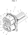
Fig. 1 is a perspective view showing a connector according to an embodiment as viewed from a front side; -
Fig. 2 is a perspective view showing the connector according to the embodiment as viewed from a rear side; -
Fig. 3 is an exploded perspective view showing the connector; -
Fig. 4 is a front view showing a first connector portion of the connector as viewed from the rear side; -
Fig. 5 is a cross-sectional view taken along a line A-A inFig. 4 ; -
Fig. 6 is a cross-sectional view taken along a line B-B inFig. 4 ; -
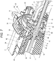
Fig. 7 is a perspective view showing the connector cut along a longitudinal direction; and -
Figs. 8A and 8B are views showing states of a retainer, in whichFig. 8A is a front view showing a state where the retainer is disposed at a non-locking position as viewed from a rear side of the first connector portion, and in whichFig. 8B is a front view showing a state where the retainer is disposed at a locking position as viewed from the rear side of the first connector portion. - Hereinafter, embodiments of the present invention will be described with reference to the drawings.
Fig. 1 is a perspective view showing a connector according to the present embodiment as viewed from a front side.Fig. 2 is a perspective view showing the connector according to the present embodiment as viewed from a rear side.Fig. 3 is an exploded perspective view showing the connector. - As shown in
Figs. 1 to 3 , theconnector 1 according to the present embodiment is to be connected to end portions of a plurality ofelectric wires 5. Each of theelectric wires 5 to which theconnector 1 is to be connected is a power line, a ground line, a signal line, or the like. A mating connector (not shown) is to be connected to a front portion of theconnector 1. - For example, the
connector 1 can be suitably used in a power-reception-side connector attached on a vehicle, which serves as a charging connector. The connector according to the present invention may be used as a power-supply-side connector attached on a vehicle, too. - The
connector 1 includes afirst connector portion 2 and asecond connector portion 3.Terminals 10 are attached to thefirst connector portion 2 and thesecond connector portion 3 from a rear side of theconnector 1. Each of theterminals 10 to be connected to theelectric wire 5 formed of, for example, a signal line is inserted and attached to thefirst connector portion 2, and each of theterminals 10 connected to theelectric wire 5 formed of, for example, a power line is inserted and attached to thesecond connector portion 3. - The
connector 1 includes theterminals 10, ahousing 20, aretainer 30, and afront holder 40. - The
terminals 10 are formed of a conductive metal material such as copper and a copper alloy, and are manufactured by cutting a round bar formed of the conductive metal material. Theterminal 10 is provided with anelectrical connection portion 11 at a front end side of theterminal 10 and an electricwire connection portion 12 at a rear end side of theterminal 10. Theterminal 10 includes aflange portion 13 extending from theterminal 10 to an outer periphery (i.e., extending outward) and provided between theelectrical connection portion 11 and the electricwire connection portion 12. Theterminal 10 is attached to thehousing 20 of theconnector 1 from a rear side of theconnector 1. - The
housing 20 includes afront housing 50 and arear housing 60. Each of thefront housing 50 and therear housing 60 is formed of a synthetic resin. Therear housing 60 is attached to a portion of thefront housing 50 forming thefirst connector portion 2 from a rear side of thefront housing 50 via theretainer 30. Thefront holder 40 is attached to the portion of thefront housing 50 forming thefirst connector portion 2 from a front side of thefront housing 50. - The
front housing 50 includes anattachment flange 52 having abolt hole 51. Theattachment flange 52 protrudes from thefront housing 50 toward an outer peripheral side of the front housing 50 (i.e., protrudes radially outward). A bolt (not shown) inserted into thebolt hole 51 of theattachment flange 52 is to be screwed into a screw hole (not shown) of a vehicle, such that theconnector 1 is attached to the vehicle. -
Fig. 4 is a front view showing the first connector portion of the connector as viewed from the rear side.Fig. 5 is a cross-sectional view taken along a line A-AinFig. 4 .Fig. 6 is a cross-sectional view taken along a line B-B inFig. 4 .Fig. 7 is a perspective view showing the connector cut along a longitudinal direction. - As shown in
Figs. 4 to 7 , thefront housing 50 is formed into a cylindrical shape. Thefront housing 50 includes apartition wall 53 at a rear side in an axial direction of theconnector 1, and thepartition wall 53 partitions an inside of thefront housing 50 in a front-rear manner, i.e., thepartition wall 53 divides an inner space of thefront housing 50 into two, a front space and a rear space. Of thefront housing 50, a portion at a front side than thepartition wall 53 is a frontperipheral wall 54, and a portion at a rear side than thepartition wall 53 is a rearperipheral wall 55. In thefront housing 50, thefront holder 40 is attached inside the frontperipheral wall 54 and theretainer 30 and therear housing 60 are attached inside the rearperipheral wall 55. - A plurality of
terminal accommodating chambers 56 are formed in thepartition wall 53 of thefront housing 50. Theterminals 10 are inserted into theterminal accommodating chambers 56 from a rear side of thefront housing 50. At a front side in an insertion direction of the terminal 10 (i.e., a direction in which theterminal 10 is inserted into the front housing 50), each of theterminal accommodating chambers 56 is provided with aseal hole 57 having a smaller diameter than theterminal accommodating chamber 56, and is further formed with athrough hole 58 having a smaller diameter than theseal hole 57. Of the terminal 10 inserted into theterminal accommodating chamber 56, theelectrical connection portion 11 is inserted into the throughhole 58, and theflange portion 13 is locked by abottom portion 56a of theterminal accommodating chamber 56 to restrict a forward movement of the terminal 10 (i.e., a movement of the terminal 10 in the insertion direction). - An
annular seal member 15 and an O-ring 14 are attached to the terminal 10 to be inserted into theterminal accommodating chamber 56 at a base portion of theelectrical connection portion 11, the base portion being connected to/ in the vicinity of/ near theflange portion 13. Accordingly, when the terminal 10 is inserted into theterminal accommodating chamber 56, the O-ring 14 is pushed into theseal hole 57 by theseal member 15, and theseal member 15 is interposed between thebottom portion 56a of theterminal accommodating chamber 56 and theflange portion 13. Accordingly, a space between the terminalaccommodating chamber 56 and the terminal 10 inserted into theterminal accommodating chamber 56 is sealed by the O-ring 14. - The
front housing 50 has a fitting recessedportion 59 inside the frontperipheral wall 54. The fitting recessedportion 59 is formed further in the front side than thepartition wall 53. - The
rear housing 60 is formed into a plate shape having a plurality of communicatingholes 61. The communicatingholes 61 communicate with the terminalaccommodating chambers 56 of thefront housing 50 when therear housing 60 is attached to thefront housing 50. - The
rear housing 60 has a plurality oflances 62. Theselances 62 are formed integrally with respective edges of the communicatingholes 61, and extend in an assembly direction to the front housing 50 (i.e., a direction in which therear housing 60 is attached to the front housing). A lockingclaw 63 protruding toward the center of the communicatinghole 61 is formed at a tip end portion of each of thelances 62. - The
rear housing 60 has a plurality of cylindrical mountingbosses 65. The mountingbosses 65 extend in the assembly direction to thefront housing 50. Ascrew 66 is to be inserted into each of the mountingboss 65 from a rear side of therear housing 60. Thescrew 66 is to be screwed into a screw hole (not shown) formed in thepartition wall 53 of thefront housing 50. Accordingly, therear housing 60 is attached into the rearperipheral wall 55 with a gap between therear housing 60 and thepartition wall 53 of thefront housing 50. - The
rear housing 60 has an outer shape that is smaller than an inner shape of the rearperipheral wall 55 of thefront housing 50. When therear housing 60 is attached to thefront housing 50, a gap is formed between an outer peripheral surface of therear housing 60 and an inner peripheral surface of the rearperipheral wall 55 in a circumferential direction. Therear housing 60 is formed with arecess 67 in a part of an outer periphery of therear housing 60. Therear housing 60 is formed with adetection hole 68 that runs through a front surface and a rear surface of therear housing 60. - The
retainer 30 is formed of a synthetic resin, and is formed into a plate shape. Theretainer 30 is disposed between thefront housing 50 and therear housing 60 when therear housing 60 is attached to thefront housing 50. Accordingly, theretainer 30 is disposed inside the rearperipheral wall 55 of thefront housing 50, and is slidably supported with respect to thehousing 20 including thefront housing 50 and therear housing 60 in a direction perpendicular to the insertion direction of the terminal 10. In other words, theretainer 30 is configured to be attached between thefront housing 50 and therear housing 60 and to be displaceable/movable along a direction perpendicular to the insertion direction between a locking position and a non-locking position. - The
retainer 30 has a plurality ofopenings 31. Theopenings 31 communicate with the terminalaccommodating chambers 56 of thefront housing 50 and the communicatingholes 61 of therear housing 60. Thelances 62 and the mountingbosses 65 of therear housing 60 are inserted into theopenings 31. - The
retainer 30 has a plurality of lockingportions 32. The lockingportions 32 are formed integrally with respective edges of theopenings 31, and protrude in an assembly direction to the front housing 50 (i.e., a direction in which theretainer 30 is attached to the front housing 50). - The
retainer 30 has an outer shape that is substantially the same as the outer shape of therear housing 60. Theretainer 30 is formed with adetection protrusion 35 in a part of an outer periphery of theretainer 30. Further, theretainer 30 is formed with acheck hole 36. -
Figs. 8A and 8B are views showing states of the retainer.Fig. 8A is a front view showing a state where the retainer is disposed at the non-locking position as viewed from a rear side of the first connector portion, andFig. 8B is a front view showing a state where the retainer is disposed at the locking position as viewed from the rear side of the first connector portion. - As shown in
Figs. 8A and 8B , theretainer 30 that is slidably supported with respect to thehousing 20 slides between the non-locking position and the locking position. - As shown in
Fig. 8A , when theretainer 30 is disposed at the non-locking position, the lockingportion 32 is disposed at a position outside theterminal accommodating chamber 56 of thefront housing 50 and the communicatinghole 61 of therear housing 60. In a state where theretainer 30 is disposed at the non-locking position, thedetection protrusion 35 is disposed outside therecess 67 of therear housing 60 and is disposed in the gap between the rearperipheral wall 55 and therear housing 60. Also thecheck hole 36 communicates with thedetection hole 68 of therear housing 60. - As shown in
Fig. 8B , when theretainer 30 is disposed at the locking position, the lockingportion 32 is disposed inside theterminal accommodating chamber 56 of thefront housing 50 and the communicatinghole 61 of therear housing 60. In a state where theretainer 30 is disposed at the locking position, thedetection protrusion 35 is disposed inside therecess 67 of therear housing 60, and thecheck hole 36 is shifted from thedetection hole 68 of therear housing 60. - The
front holder 40 is formed of a synthetic resin and has a plurality ofaccommodating holes 41. A rear portion of thefront holder 40 is afitting portion 42. Thefitting portion 42 is fitted to the fitting recessedportion 59 of thefront housing 50, thereby attaching thefront holder 40 to thefront housing 50 and disposing thefront holder 40 inside the frontperipheral wall 54. When thefront holder 40 is attached to thefront housing 50, theaccommodating hole 41 communicates with the throughhole 58 of thepartition wall 53 of thefront housing 50. Accordingly, theelectrical connection portion 11 of the terminal 10 that has passed through the throughhole 58 is accommodated in theaccommodating hole 41 of thefront holder 40. - Next, how the terminal 10 is attached to the
housing 20 provided with theretainer 30 and thefront holder 40 will be described. - To attach the terminal 10 to the
housing 20, first, theretainer 30 is disposed in the non-locking position (seeFig. 8A ). Accordingly, the lockingportion 32 of theretainer 30 is disposed at a position outside theterminal accommodating chamber 56 of thefront housing 50 and the communicatinghole 61 of therear housing 60. - In this state, the terminal 10 is inserted and pushed into the communicating
hole 61 of therear housing 60 from the rear side of thehousing 20, and theelectrical connection portion 11 is inserted through the throughhole 58 of thefront housing 50 and is accommodated in theterminal accommodating chamber 56. Then, each of thelances 62 of therear housing 60 is elastically deformed by the lockingclaw 63 being pushed outward by theflange portion 13, and thereafter thelance 62 is restored when theflange portion 13 reaches to a front side of the lockingclaw 63. Accordingly, theflange portion 13 of the terminal 10 is locked by the lockingclaw 63 of thelance 62, a rearward movement in the insertion direction of the terminal 10 is restricted (i.e., a movement in a direction opposite to the insertion direction of the terminal 10), and the terminal 10 is prevented from coming off. - In this manner, when the terminal 10 is accommodated in the
terminal accommodating chamber 56, theseal member 15 attached to the root of theelectrical connection portion 11 connected to theflange portion 13 pushes the O-ring 14 into theseal hole 57, and theseal member 15 is interposed between thebottom portion 56a of theterminal accommodating chamber 56 and theflange portion 13. Accordingly, a space between the terminal 10 and theterminal accommodating chamber 56 is sealed by the O-ring 14. - Next, the
retainer 30 disposed at the non-locking position slides to the locking position (seeFig. 8B ). Then, each lockingportion 32 of theretainer 30 comes to a rear side of theflange portion 13 of the terminal 10 accommodated in theterminal accommodating chamber 56. Accordingly, theflange portion 13 of the terminal 10 is locked at two positions by thelance 62 of therear housing 60 and the lockingportion 32 of theretainer 30. - As described above, according to the
connector 1 in the present embodiment, when theretainer 30 moves from the non-locking position to the locking portion, the terminal 10 can be locked by the lockingportion 32 of theretainer 30 and thelance 62 of therear housing 60. Compared with a case where the terminal 10 is locked by thelance 62 only, according to theconnector 1 in the present embodiment, the terminal 10 can be locked in a well-balanced manner, and inclination of the terminal 10 due to a biasing force can be prevented. Further, therear housing 60 is provided with thelance 62, so that a lance of thefront housing 50 is not necessary, and a structure can be simplified. Accordingly, a cost and a size can be reduced. Since a hole for removing a mold for molding a lance in the front housing is not formed in thefront housing 50, good sealing performance of thefront housing 50 can be ensured. - The
front housing 50 has the rearperipheral wall 55 that surrounds theretainer 30. Accordingly, a periphery of theretainer 30 attached between thefront housing 50 and therear housing 60 is covered by the rearperipheral wall 55 of thefront housing 50, so that theretainer 30 can be protected, and an erroneous operation due to careless contact with theretainer 30 can be prevented. - The
retainer 30 has adetection protrusion 35 protruding from an outer peripheral surface of therear housing 60 in a radial direction of the connector when theretainer 30 is at the non-locking position. In other words, theretainer 30 has thedetection protrusion 35 configured to, when theretainer 30 is disposed at the non-locking position, be disposed above/ at an outer side of the outer peripheral surface of therear housing 60 in the radial direction of the connector in a protruding manner. Therefore, a locking state of the terminal 10 by the lockingportion 32 of theretainer 30 can be easily confirmed by visually checking a protruding state of thedetection protrusion 35 of theretainer 30 on the outer peripheral surface of therear housing 60. For example, when a cover configured to cover an outer periphery of therear housing 60 is attached, a locking state of the terminal 10 by the lockingportion 32 of theretainer 30 can be easily confirmed by checking whether the cover interferes with thedetection protrusion 35. - Further, the
rear housing 60 is formed with thedetection hole 68, and theretainer 30 is formed with thecheck hole 36 that communicates with thedetection hole 68 of therear housing 60 in a state where theretainer 30 is disposed at the non-locking position. Therefore, a locking state of the terminal 10 by the lockingportion 32 of theretainer 30 can be easily confirmed by inserting an inspection pin into thedetection hole 68 and checking a length of an inserted part of the inspection pin. In addition, a locking state of the terminal 10 by the lockingportion 32 of theretainer 30 can also be easily confirmed by visually checking whether thecheck hole 36 of theretainer 30 communicates with thedetection hole 68. - When the
retainer 30 is disposed at the locking position, thedetection protrusion 35, which had been disposed above the outer peripheral surface of therear housing 60 in the radial direction in a protruding manner when theretainer 30 was at the non-locking position, is accommodated within therecess 67 of therear housing 60. Therefore, an operator can easily confirm a locking state of the terminal 10 by the lockingportion 32 of theretainer 30 by visually checking whether thedetection protrusion 35 of theretainer 30 is disposed in a protruding manner or not above the outer peripheral surface of therear housing 60. Also, when a cover configured to cover the outer periphery of therear housing 60 is attached, the operator can also easily confirm a locking state of the terminal 10 by the lockingportion 32 of theretainer 30 by checking whether the cover interferes with thedetection protrusion 35 or not. - Further, when the
retainer 30 is disposed at the locking position, thecheck hole 36 is disposed at a position shifted from thedetection hole 68 of therear housing 60. Therefore, an operator can easily confirm a locking state of the terminal 10 by the lockingportion 32 of theretainer 30 by inserting an inspection pin into thedetection hole 68 and checking the length of the inserted part/protruding part of the inspection pin. In addition, the operator can easily confirm a locking state of the terminal 10 by the lockingportion 32 of theretainer 30 by visually checking whether thecheck hole 36 of theretainer 30 communicates with thedetection hole 68. - While the present invention has been described with reference to certain exemplary embodiments thereof, the scope of the present invention is not limited to the exemplary embodiments described above, and it will be understood by those skilled in the art that various changes and modifications may be made therein without departing from the scope of the present invention as defined by the appended claims.
- According to an aspect of the embodiments described above, a connector includes a terminal (10), a housing (20) configured to accommodate the terminal (10) and a retainer (30) including a locking portion (32) configured to lock the terminal (10) when the terminal (10) is accommodated in the housing (20). The housing (20) includes a front housing (50) having a terminal accommodating chamber (56) into which the terminal (10) is configured to be inserted and in which the terminal (10) is to be accommodated and a rear housing (60) configured to be attached to the front housing (50) from a rear side of an insertion direction in which the terminal (10) is inserted into the terminal accommodating chamber (56), the rear housing (60) including a lance (62) configured to, when the terminal (10) is accommodated in the terminal accommodating chamber (56), lock a rear portion of the terminal (10) in the insertion direction. The retainer (30) is configured to be attached between the front housing (50) and the rear housing (60) and to be displaceable along a direction perpendicular to the insertion direction between a locking position and a non-locking position. The retainer (30) moves from the non-locking position to the locking portion and the locking portion (32) locks the rear portion of the terminal (10) in the insertion direction accommodated in the terminal accommodating chamber (56).
- According to the connector having the above described configuration, when the retainer moves from the non-locking position to the locking portion, the terminal can be locked by the locking portion of the retainer and the lance of the rear housing. Compared with a case where the terminal is locked by the lance only, the terminal can be locked in a well-balanced manner, and inclination of the terminal due to a biasing force can be prevented. Further, the rear housing is provided with the lance, so that a lance of the front housing is not necessary, and a structure can be simplified. Accordingly, a cost and a size can be reduced. Since a hole for removing a mold for molding a lance in the front housing is not formed in the front housing, good sealing performance of the front housing can be ensured.
- The front housing (50) may have a peripheral wall (rear peripheral wall 55) which surrounds the retainer (30) when the retainer (30) is attached to the front housing (50).
- According to the connector having the above described configuration, since a peripheral surface of the retainer attached between the front housing and the rear housing is covered by the peripheral wall of the front housing, the retainer can be protected, and an erroneous operation due to careless contact with the retainer can be prevented.
- The retainer (30) may have a detection protrusion (35) protruding from an outer peripheral surface of the rear housing (60) in a radial direction of the connector when the retainer (30) is at the non-locking position.
- According to the connector having the above described configuration, a locking state of the terminal by the locking portion of the retainer can be easily confirmed by visually checking a protruding state of the detection protrusion of the retainer from the outer peripheral surface of the rear housing. Also, when a cover configured to cover an outer periphery of the rear housing is attached, a locking state of the terminal by the locking portion of the retainer can be easily confirmed by checking whether the cover interferes with the detection protrusion.
- The rear housing (60) may be formed with a detection hole (68). The retainer (30) may be formed with a check hole (36) configured to, when the retainer (30) is at the non-locking position, communicate with the detection hole (68) of the rear housing (60).
- According to the connector having the above described configuration, the check hole of the retainer communicates with the detection hole of the rear housing in a state where the retainer is disposed at the non-locking position. Therefore, a locking state of the terminal by the locking portion of the retainer can be easily confirmed by inserting an inspection pin into the detection hole and checking an insertion length of the inspection pin. In addition, a locking state of the terminal by the locking portion of the retainer can be easily confirmed by visually checking whether the check hole of the retainer communicates with the detection hole.
Claims (4)
- A connector including:a terminal;a housing configured to accommodate the terminal; anda retainer including a locking portion configured to lock the terminal when the terminal is accommodated in the housing;wherein the housing includes:a front housing having a terminal accommodating chamber into which the terminal is configured to be inserted and in which the terminal is to be accommodated; anda rear housing configured to be attached to the front housing from a rear side of an insertion direction in which the terminal is inserted into the terminal accommodating chamber, the rear housing including a lance configured to, when the terminal is accommodated in the terminal accommodating chamber, lock a rear portion of the terminal in the insertion direction,wherein the retainer is configured to be attached between the front housing and the rear housing and to be displaceable along a direction perpendicular to the insertion direction between a locking position and a non-locking position, andwherein the retainer moves from the non-locking position to the locking portion and the locking portion locks the rear portion of the terminal in the insertion direction accommodated in the terminal accommodating chamber.
- The connector according to claim 1,
wherein the front housing has a peripheral wall which surrounds the retainer when the retainer is attached to the front housing. - The connector according to claim 1 or 2,
wherein the retainer has a detection protrusion protruding from an outer peripheral surface of the rear housing in a radial direction of the connector when the retainer is at the non-locking position. - The connector according to any one of claims 1 to 3,
wherein the rear housing is formed with a detection hole, and
wherein the retainer is formed with a check hole configured to, when the retainer is at the non-locking position, communicate with the detection hole of the rear housing.
Applications Claiming Priority (1)
| Application Number | Priority Date | Filing Date | Title |
|---|---|---|---|
| JP2020017193A JP7044813B2 (en) | 2020-02-04 | 2020-02-04 | connector |
Publications (2)
| Publication Number | Publication Date |
|---|---|
| EP3863122A1 true EP3863122A1 (en) | 2021-08-11 |
| EP3863122B1 EP3863122B1 (en) | 2022-09-21 |
Family
ID=74285230
Family Applications (1)
| Application Number | Title | Priority Date | Filing Date |
|---|---|---|---|
| EP21153437.5A Active EP3863122B1 (en) | 2020-02-04 | 2021-01-26 | Connector |
Country Status (4)
| Country | Link |
|---|---|
| US (1) | US11336046B2 (en) |
| EP (1) | EP3863122B1 (en) |
| JP (1) | JP7044813B2 (en) |
| CN (1) | CN113285269B (en) |
Families Citing this family (4)
| Publication number | Priority date | Publication date | Assignee | Title |
|---|---|---|---|---|
| IT202100010583A1 (en) * | 2021-04-27 | 2022-10-27 | Te Connectivity Italia Distribution Srl | SYSTEM AND METHOD OF BLOCKING ELECTRICAL TERMINALS |
| KR102590201B1 (en) * | 2021-05-24 | 2023-10-17 | 주식회사 유라 | Car charging connector |
| JP7639736B2 (en) * | 2022-03-01 | 2025-03-05 | 住友電装株式会社 | Wire Connector |
| JP7596046B2 (en) * | 2022-11-30 | 2024-12-09 | 矢崎総業株式会社 | Charging inlet |
Citations (4)
| Publication number | Priority date | Publication date | Assignee | Title |
|---|---|---|---|---|
| US5586917A (en) * | 1994-03-17 | 1996-12-24 | Yazaki Corporation | Connector having an ascertainment hole for visually checking engagement |
| US6071153A (en) * | 1998-02-19 | 2000-06-06 | Delphi Technologies, Inc. | Dual lock for multi-row electrical connector system |
| JP2000215941A (en) * | 1999-01-26 | 2000-08-04 | Japan Aviation Electronics Industry Ltd | Double locking connector |
| JP2018200791A (en) | 2017-05-26 | 2018-12-20 | 矢崎総業株式会社 | connector |
Family Cites Families (18)
| Publication number | Priority date | Publication date | Assignee | Title |
|---|---|---|---|---|
| JP2503320B2 (en) * | 1991-04-04 | 1996-06-05 | 矢崎総業株式会社 | Connector with dual locking mechanism |
| JP2799446B2 (en) * | 1993-07-22 | 1998-09-17 | 矢崎総業株式会社 | connector |
| JP4076590B2 (en) * | 1994-08-04 | 2008-04-16 | 住友電装株式会社 | Connector with retainer |
| JP3634111B2 (en) * | 1997-04-14 | 2005-03-30 | 住友電装株式会社 | Female connector |
| JP3337124B2 (en) * | 1997-11-28 | 2002-10-21 | 住友電装株式会社 | connector |
| JP3685314B2 (en) * | 1999-08-02 | 2005-08-17 | 矢崎総業株式会社 | Female connector with terminal lock and electrical connector with terminal lock |
| DE10045706B4 (en) * | 1999-09-16 | 2004-08-19 | Yazaki Corp. | Waterproof connector, sealing member and method of assembling the waterproof connector |
| JP2005166611A (en) * | 2003-12-05 | 2005-06-23 | Sumitomo Wiring Syst Ltd | Connector |
| JP4922424B2 (en) * | 2010-03-05 | 2012-04-25 | 日本航空電子工業株式会社 | Waterproof connector |
| JP5524789B2 (en) * | 2010-09-27 | 2014-06-18 | 矢崎総業株式会社 | connector |
| JP2013218822A (en) * | 2012-04-05 | 2013-10-24 | Yazaki Corp | Connector attachment structure and connector attaching method |
| JP5751205B2 (en) * | 2012-04-11 | 2015-07-22 | 住友電装株式会社 | connector |
| JP6105263B2 (en) * | 2012-11-29 | 2017-03-29 | 矢崎総業株式会社 | connector |
| EP2846416B1 (en) * | 2013-08-23 | 2020-02-12 | TE Connectivity India Private Limited | Connector housing with a monolithically integrated terminal positioning assurance device |
| US9153894B2 (en) * | 2013-11-11 | 2015-10-06 | Yazaki North America, Inc. | Terminal position assurance with dual primary lock reinforcement and independent secondary lock |
| JP2018120687A (en) * | 2017-01-24 | 2018-08-02 | 住友電装株式会社 | connector |
| EP3462820B1 (en) * | 2017-09-29 | 2021-08-04 | Hosiden Corporation | Connector box and method of its assembly |
| JP6626870B2 (en) * | 2017-10-05 | 2019-12-25 | 矢崎総業株式会社 | connector |
-
2020
- 2020-02-04 JP JP2020017193A patent/JP7044813B2/en active Active
-
2021
- 2021-01-26 EP EP21153437.5A patent/EP3863122B1/en active Active
- 2021-02-01 CN CN202110136229.8A patent/CN113285269B/en active Active
- 2021-02-04 US US17/167,103 patent/US11336046B2/en active Active
Patent Citations (4)
| Publication number | Priority date | Publication date | Assignee | Title |
|---|---|---|---|---|
| US5586917A (en) * | 1994-03-17 | 1996-12-24 | Yazaki Corporation | Connector having an ascertainment hole for visually checking engagement |
| US6071153A (en) * | 1998-02-19 | 2000-06-06 | Delphi Technologies, Inc. | Dual lock for multi-row electrical connector system |
| JP2000215941A (en) * | 1999-01-26 | 2000-08-04 | Japan Aviation Electronics Industry Ltd | Double locking connector |
| JP2018200791A (en) | 2017-05-26 | 2018-12-20 | 矢崎総業株式会社 | connector |
Also Published As
| Publication number | Publication date |
|---|---|
| US11336046B2 (en) | 2022-05-17 |
| US20210242620A1 (en) | 2021-08-05 |
| CN113285269A (en) | 2021-08-20 |
| EP3863122B1 (en) | 2022-09-21 |
| JP7044813B2 (en) | 2022-03-30 |
| CN113285269B (en) | 2023-06-27 |
| JP2021125340A (en) | 2021-08-30 |
Similar Documents
| Publication | Publication Date | Title |
|---|---|---|
| US11336046B2 (en) | Charging connector | |
| EP2693574B1 (en) | Shield connector | |
| US9455525B2 (en) | Connector with flexible conductive member to isolate terminal from vibrations in a wire | |
| US7481674B2 (en) | Electrical connector | |
| JP5316875B2 (en) | Shield connector mounting structure, shield connector | |
| US11646522B2 (en) | Male connector and connector device | |
| EP3547464B1 (en) | Elelctrical connector | |
| EP3783748B1 (en) | Connector | |
| EP3751675A1 (en) | Housing comprising an engaging piece inserted into a seal mounting portion and abutting said seal mounting portion | |
| JP4992659B2 (en) | connector | |
| US12327952B2 (en) | Electrical connector with retaining member | |
| WO2014181693A1 (en) | Retaining structure for terminal fitting | |
| EP4009447A1 (en) | Connecter terminal structure | |
| CN117397128A (en) | Terminal block unit | |
| EP3793033B1 (en) | A device for electrically connecting one or more electrical connectors to a printed circuit board | |
| JP2019083184A (en) | connector | |
| US12476418B2 (en) | Connector | |
| CN119895674A (en) | Electrical connector components | |
| EP4668501A1 (en) | Connector | |
| CN108963666B (en) | Connector with a locking member | |
| JP2014103021A (en) | Shield connector | |
| US20260045729A1 (en) | Connector | |
| CN223680523U (en) | Grounding connector | |
| US12548923B2 (en) | Terminal connection structure | |
| US20250300389A1 (en) | Connector and wire harness |
Legal Events
| Date | Code | Title | Description |
|---|---|---|---|
| PUAI | Public reference made under article 153(3) epc to a published international application that has entered the european phase |
Free format text: ORIGINAL CODE: 0009012 |
|
| STAA | Information on the status of an ep patent application or granted ep patent |
Free format text: STATUS: REQUEST FOR EXAMINATION WAS MADE |
|
| 17P | Request for examination filed |
Effective date: 20210126 |
|
| AK | Designated contracting states |
Kind code of ref document: A1 Designated state(s): AL AT BE BG CH CY CZ DE DK EE ES FI FR GB GR HR HU IE IS IT LI LT LU LV MC MK MT NL NO PL PT RO RS SE SI SK SM TR |
|
| GRAP | Despatch of communication of intention to grant a patent |
Free format text: ORIGINAL CODE: EPIDOSNIGR1 |
|
| STAA | Information on the status of an ep patent application or granted ep patent |
Free format text: STATUS: GRANT OF PATENT IS INTENDED |
|
| RIC1 | Information provided on ipc code assigned before grant |
Ipc: H01R 13/506 20060101ALN20220621BHEP Ipc: H01R 13/424 20060101ALI20220621BHEP Ipc: H01R 13/436 20060101AFI20220621BHEP |
|
| INTG | Intention to grant announced |
Effective date: 20220708 |
|
| GRAS | Grant fee paid |
Free format text: ORIGINAL CODE: EPIDOSNIGR3 |
|
| GRAA | (expected) grant |
Free format text: ORIGINAL CODE: 0009210 |
|
| STAA | Information on the status of an ep patent application or granted ep patent |
Free format text: STATUS: THE PATENT HAS BEEN GRANTED |
|
| AK | Designated contracting states |
Kind code of ref document: B1 Designated state(s): AL AT BE BG CH CY CZ DE DK EE ES FI FR GB GR HR HU IE IS IT LI LT LU LV MC MK MT NL NO PL PT RO RS SE SI SK SM TR |
|
| REG | Reference to a national code |
Ref country code: GB Ref legal event code: FG4D |
|
| REG | Reference to a national code |
Ref country code: CH Ref legal event code: EP |
|
| REG | Reference to a national code |
Ref country code: IE Ref legal event code: FG4D |
|
| REG | Reference to a national code |
Ref country code: DE Ref legal event code: R096 Ref document number: 602021000442 Country of ref document: DE |
|
| REG | Reference to a national code |
Ref country code: AT Ref legal event code: REF Ref document number: 1520431 Country of ref document: AT Kind code of ref document: T Effective date: 20221015 |
|
| REG | Reference to a national code |
Ref country code: LT Ref legal event code: MG9D |
|
| REG | Reference to a national code |
Ref country code: NL Ref legal event code: MP Effective date: 20220921 |
|
| PG25 | Lapsed in a contracting state [announced via postgrant information from national office to epo] |
Ref country code: SE Free format text: LAPSE BECAUSE OF FAILURE TO SUBMIT A TRANSLATION OF THE DESCRIPTION OR TO PAY THE FEE WITHIN THE PRESCRIBED TIME-LIMIT Effective date: 20220921 Ref country code: RS Free format text: LAPSE BECAUSE OF FAILURE TO SUBMIT A TRANSLATION OF THE DESCRIPTION OR TO PAY THE FEE WITHIN THE PRESCRIBED TIME-LIMIT Effective date: 20220921 Ref country code: NO Free format text: LAPSE BECAUSE OF FAILURE TO SUBMIT A TRANSLATION OF THE DESCRIPTION OR TO PAY THE FEE WITHIN THE PRESCRIBED TIME-LIMIT Effective date: 20221221 Ref country code: LV Free format text: LAPSE BECAUSE OF FAILURE TO SUBMIT A TRANSLATION OF THE DESCRIPTION OR TO PAY THE FEE WITHIN THE PRESCRIBED TIME-LIMIT Effective date: 20220921 Ref country code: LT Free format text: LAPSE BECAUSE OF FAILURE TO SUBMIT A TRANSLATION OF THE DESCRIPTION OR TO PAY THE FEE WITHIN THE PRESCRIBED TIME-LIMIT Effective date: 20220921 Ref country code: FI Free format text: LAPSE BECAUSE OF FAILURE TO SUBMIT A TRANSLATION OF THE DESCRIPTION OR TO PAY THE FEE WITHIN THE PRESCRIBED TIME-LIMIT Effective date: 20220921 |
|
| REG | Reference to a national code |
Ref country code: AT Ref legal event code: MK05 Ref document number: 1520431 Country of ref document: AT Kind code of ref document: T Effective date: 20220921 |
|
| PG25 | Lapsed in a contracting state [announced via postgrant information from national office to epo] |
Ref country code: HR Free format text: LAPSE BECAUSE OF FAILURE TO SUBMIT A TRANSLATION OF THE DESCRIPTION OR TO PAY THE FEE WITHIN THE PRESCRIBED TIME-LIMIT Effective date: 20220921 Ref country code: GR Free format text: LAPSE BECAUSE OF FAILURE TO SUBMIT A TRANSLATION OF THE DESCRIPTION OR TO PAY THE FEE WITHIN THE PRESCRIBED TIME-LIMIT Effective date: 20221222 |
|
| PG25 | Lapsed in a contracting state [announced via postgrant information from national office to epo] |
Ref country code: SM Free format text: LAPSE BECAUSE OF FAILURE TO SUBMIT A TRANSLATION OF THE DESCRIPTION OR TO PAY THE FEE WITHIN THE PRESCRIBED TIME-LIMIT Effective date: 20220921 Ref country code: RO Free format text: LAPSE BECAUSE OF FAILURE TO SUBMIT A TRANSLATION OF THE DESCRIPTION OR TO PAY THE FEE WITHIN THE PRESCRIBED TIME-LIMIT Effective date: 20220921 Ref country code: PT Free format text: LAPSE BECAUSE OF FAILURE TO SUBMIT A TRANSLATION OF THE DESCRIPTION OR TO PAY THE FEE WITHIN THE PRESCRIBED TIME-LIMIT Effective date: 20230123 Ref country code: ES Free format text: LAPSE BECAUSE OF FAILURE TO SUBMIT A TRANSLATION OF THE DESCRIPTION OR TO PAY THE FEE WITHIN THE PRESCRIBED TIME-LIMIT Effective date: 20220921 Ref country code: CZ Free format text: LAPSE BECAUSE OF FAILURE TO SUBMIT A TRANSLATION OF THE DESCRIPTION OR TO PAY THE FEE WITHIN THE PRESCRIBED TIME-LIMIT Effective date: 20220921 Ref country code: AT Free format text: LAPSE BECAUSE OF FAILURE TO SUBMIT A TRANSLATION OF THE DESCRIPTION OR TO PAY THE FEE WITHIN THE PRESCRIBED TIME-LIMIT Effective date: 20220921 |
|
| PG25 | Lapsed in a contracting state [announced via postgrant information from national office to epo] |
Ref country code: SK Free format text: LAPSE BECAUSE OF FAILURE TO SUBMIT A TRANSLATION OF THE DESCRIPTION OR TO PAY THE FEE WITHIN THE PRESCRIBED TIME-LIMIT Effective date: 20220921 Ref country code: PL Free format text: LAPSE BECAUSE OF FAILURE TO SUBMIT A TRANSLATION OF THE DESCRIPTION OR TO PAY THE FEE WITHIN THE PRESCRIBED TIME-LIMIT Effective date: 20220921 Ref country code: IS Free format text: LAPSE BECAUSE OF FAILURE TO SUBMIT A TRANSLATION OF THE DESCRIPTION OR TO PAY THE FEE WITHIN THE PRESCRIBED TIME-LIMIT Effective date: 20230121 Ref country code: EE Free format text: LAPSE BECAUSE OF FAILURE TO SUBMIT A TRANSLATION OF THE DESCRIPTION OR TO PAY THE FEE WITHIN THE PRESCRIBED TIME-LIMIT Effective date: 20220921 |
|
| REG | Reference to a national code |
Ref country code: DE Ref legal event code: R097 Ref document number: 602021000442 Country of ref document: DE |
|
| PG25 | Lapsed in a contracting state [announced via postgrant information from national office to epo] |
Ref country code: NL Free format text: LAPSE BECAUSE OF FAILURE TO SUBMIT A TRANSLATION OF THE DESCRIPTION OR TO PAY THE FEE WITHIN THE PRESCRIBED TIME-LIMIT Effective date: 20220921 Ref country code: AL Free format text: LAPSE BECAUSE OF FAILURE TO SUBMIT A TRANSLATION OF THE DESCRIPTION OR TO PAY THE FEE WITHIN THE PRESCRIBED TIME-LIMIT Effective date: 20220921 |
|
| PLBE | No opposition filed within time limit |
Free format text: ORIGINAL CODE: 0009261 |
|
| STAA | Information on the status of an ep patent application or granted ep patent |
Free format text: STATUS: NO OPPOSITION FILED WITHIN TIME LIMIT |
|
| PG25 | Lapsed in a contracting state [announced via postgrant information from national office to epo] |
Ref country code: DK Free format text: LAPSE BECAUSE OF FAILURE TO SUBMIT A TRANSLATION OF THE DESCRIPTION OR TO PAY THE FEE WITHIN THE PRESCRIBED TIME-LIMIT Effective date: 20220921 |
|
| 26N | No opposition filed |
Effective date: 20230622 |
|
| PG25 | Lapsed in a contracting state [announced via postgrant information from national office to epo] |
Ref country code: SI Free format text: LAPSE BECAUSE OF FAILURE TO SUBMIT A TRANSLATION OF THE DESCRIPTION OR TO PAY THE FEE WITHIN THE PRESCRIBED TIME-LIMIT Effective date: 20220921 |
|
| PG25 | Lapsed in a contracting state [announced via postgrant information from national office to epo] |
Ref country code: LU Free format text: LAPSE BECAUSE OF NON-PAYMENT OF DUE FEES Effective date: 20230126 |
|
| REG | Reference to a national code |
Ref country code: BE Ref legal event code: MM Effective date: 20230131 |
|
| PG25 | Lapsed in a contracting state [announced via postgrant information from national office to epo] |
Ref country code: FR Free format text: LAPSE BECAUSE OF NON-PAYMENT OF DUE FEES Effective date: 20230131 Ref country code: BE Free format text: LAPSE BECAUSE OF NON-PAYMENT OF DUE FEES Effective date: 20230131 |
|
| PG25 | Lapsed in a contracting state [announced via postgrant information from national office to epo] |
Ref country code: IE Free format text: LAPSE BECAUSE OF NON-PAYMENT OF DUE FEES Effective date: 20230126 |
|
| PG25 | Lapsed in a contracting state [announced via postgrant information from national office to epo] |
Ref country code: IT Free format text: LAPSE BECAUSE OF FAILURE TO SUBMIT A TRANSLATION OF THE DESCRIPTION OR TO PAY THE FEE WITHIN THE PRESCRIBED TIME-LIMIT Effective date: 20220921 |
|
| PG25 | Lapsed in a contracting state [announced via postgrant information from national office to epo] |
Ref country code: MC Free format text: LAPSE BECAUSE OF FAILURE TO SUBMIT A TRANSLATION OF THE DESCRIPTION OR TO PAY THE FEE WITHIN THE PRESCRIBED TIME-LIMIT Effective date: 20220921 |
|
| PG25 | Lapsed in a contracting state [announced via postgrant information from national office to epo] |
Ref country code: MC Free format text: LAPSE BECAUSE OF FAILURE TO SUBMIT A TRANSLATION OF THE DESCRIPTION OR TO PAY THE FEE WITHIN THE PRESCRIBED TIME-LIMIT Effective date: 20220921 |
|
| REG | Reference to a national code |
Ref country code: CH Ref legal event code: PL |
|
| PG25 | Lapsed in a contracting state [announced via postgrant information from national office to epo] |
Ref country code: CH Free format text: LAPSE BECAUSE OF NON-PAYMENT OF DUE FEES Effective date: 20240131 |
|
| PG25 | Lapsed in a contracting state [announced via postgrant information from national office to epo] |
Ref country code: CH Free format text: LAPSE BECAUSE OF NON-PAYMENT OF DUE FEES Effective date: 20240131 |
|
| PG25 | Lapsed in a contracting state [announced via postgrant information from national office to epo] |
Ref country code: BG Free format text: LAPSE BECAUSE OF FAILURE TO SUBMIT A TRANSLATION OF THE DESCRIPTION OR TO PAY THE FEE WITHIN THE PRESCRIBED TIME-LIMIT Effective date: 20220921 |
|
| PG25 | Lapsed in a contracting state [announced via postgrant information from national office to epo] |
Ref country code: BG Free format text: LAPSE BECAUSE OF FAILURE TO SUBMIT A TRANSLATION OF THE DESCRIPTION OR TO PAY THE FEE WITHIN THE PRESCRIBED TIME-LIMIT Effective date: 20220921 |
|
| PG25 | Lapsed in a contracting state [announced via postgrant information from national office to epo] |
Ref country code: CY Free format text: LAPSE BECAUSE OF FAILURE TO SUBMIT A TRANSLATION OF THE DESCRIPTION OR TO PAY THE FEE WITHIN THE PRESCRIBED TIME-LIMIT; INVALID AB INITIO Effective date: 20210126 |
|
| PG25 | Lapsed in a contracting state [announced via postgrant information from national office to epo] |
Ref country code: HU Free format text: LAPSE BECAUSE OF FAILURE TO SUBMIT A TRANSLATION OF THE DESCRIPTION OR TO PAY THE FEE WITHIN THE PRESCRIBED TIME-LIMIT; INVALID AB INITIO Effective date: 20210126 |
|
| GBPC | Gb: european patent ceased through non-payment of renewal fee |
Effective date: 20250126 |
|
| PG25 | Lapsed in a contracting state [announced via postgrant information from national office to epo] |
Ref country code: GB Free format text: LAPSE BECAUSE OF NON-PAYMENT OF DUE FEES Effective date: 20250126 |
|
| PG25 | Lapsed in a contracting state [announced via postgrant information from national office to epo] |
Ref country code: TR Free format text: LAPSE BECAUSE OF FAILURE TO SUBMIT A TRANSLATION OF THE DESCRIPTION OR TO PAY THE FEE WITHIN THE PRESCRIBED TIME-LIMIT Effective date: 20220921 |
|
| PGFP | Annual fee paid to national office [announced via postgrant information from national office to epo] |
Ref country code: DE Payment date: 20251203 Year of fee payment: 6 |