EP3863119B1 - Electrical terminal and method of forming same - Google Patents
Electrical terminal and method of forming same Download PDFInfo
- Publication number
- EP3863119B1 EP3863119B1 EP21154739.3A EP21154739A EP3863119B1 EP 3863119 B1 EP3863119 B1 EP 3863119B1 EP 21154739 A EP21154739 A EP 21154739A EP 3863119 B1 EP3863119 B1 EP 3863119B1
- Authority
- EP
- European Patent Office
- Prior art keywords
- base portion
- planar
- attachment portion
- electrical terminal
- accordance
- Prior art date
- Legal status (The legal status is an assumption and is not a legal conclusion. Google has not performed a legal analysis and makes no representation as to the accuracy of the status listed.)
- Active
Links
Images




Classifications
-
- H—ELECTRICITY
- H01—ELECTRIC ELEMENTS
- H01R—ELECTRICALLY-CONDUCTIVE CONNECTIONS; STRUCTURAL ASSOCIATIONS OF A PLURALITY OF MUTUALLY-INSULATED ELECTRICAL CONNECTING ELEMENTS; COUPLING DEVICES; CURRENT COLLECTORS
- H01R13/00—Details of coupling devices of the kinds covered by groups H01R12/70 or H01R24/00 - H01R33/00
- H01R13/40—Securing contact members in or to a base or case; Insulating of contact members
-
- H—ELECTRICITY
- H01—ELECTRIC ELEMENTS
- H01R—ELECTRICALLY-CONDUCTIVE CONNECTIONS; STRUCTURAL ASSOCIATIONS OF A PLURALITY OF MUTUALLY-INSULATED ELECTRICAL CONNECTING ELEMENTS; COUPLING DEVICES; CURRENT COLLECTORS
- H01R11/00—Individual connecting elements providing two or more spaced connecting locations for conductive members which are, or may be, thereby interconnected, e.g. end pieces for wires or cables supported by the wire or cable and having means for facilitating electrical connection to some other wire, terminal, or conductive member, blocks of binding posts
- H01R11/11—End pieces or tapping pieces for wires, supported by the wire and for facilitating electrical connection to some other wire, terminal or conductive member
- H01R11/16—End pieces terminating in a soldering tip or socket
-
- H—ELECTRICITY
- H01—ELECTRIC ELEMENTS
- H01R—ELECTRICALLY-CONDUCTIVE CONNECTIONS; STRUCTURAL ASSOCIATIONS OF A PLURALITY OF MUTUALLY-INSULATED ELECTRICAL CONNECTING ELEMENTS; COUPLING DEVICES; CURRENT COLLECTORS
- H01R12/00—Structural associations of a plurality of mutually-insulated electrical connecting elements, specially adapted for printed circuits, e.g. printed circuit boards [PCB], flat or ribbon cables, or like generally planar structures, e.g. terminal strips, terminal blocks; Coupling devices specially adapted for printed circuits, flat or ribbon cables, or like generally planar structures; Terminals specially adapted for contact with, or insertion into, printed circuits, flat or ribbon cables, or like generally planar structures
- H01R12/50—Fixed connections
- H01R12/51—Fixed connections for rigid printed circuits or like structures
- H01R12/55—Fixed connections for rigid printed circuits or like structures characterised by the terminals
- H01R12/57—Fixed connections for rigid printed circuits or like structures characterised by the terminals surface mounting terminals
-
- H—ELECTRICITY
- H01—ELECTRIC ELEMENTS
- H01R—ELECTRICALLY-CONDUCTIVE CONNECTIONS; STRUCTURAL ASSOCIATIONS OF A PLURALITY OF MUTUALLY-INSULATED ELECTRICAL CONNECTING ELEMENTS; COUPLING DEVICES; CURRENT COLLECTORS
- H01R13/00—Details of coupling devices of the kinds covered by groups H01R12/70 or H01R24/00 - H01R33/00
- H01R13/02—Contact members
- H01R13/03—Contact members characterised by the material, e.g. plating, or coating materials
-
- H—ELECTRICITY
- H01—ELECTRIC ELEMENTS
- H01R—ELECTRICALLY-CONDUCTIVE CONNECTIONS; STRUCTURAL ASSOCIATIONS OF A PLURALITY OF MUTUALLY-INSULATED ELECTRICAL CONNECTING ELEMENTS; COUPLING DEVICES; CURRENT COLLECTORS
- H01R4/00—Electrically-conductive connections between two or more conductive members in direct contact, i.e. touching one another; Means for effecting or maintaining such contact; Electrically-conductive connections having two or more spaced connecting locations for conductors and using contact members penetrating insulation
- H01R4/10—Electrically-conductive connections between two or more conductive members in direct contact, i.e. touching one another; Means for effecting or maintaining such contact; Electrically-conductive connections having two or more spaced connecting locations for conductors and using contact members penetrating insulation effected solely by twisting, wrapping, bending, crimping, or other permanent deformation
- H01R4/18—Electrically-conductive connections between two or more conductive members in direct contact, i.e. touching one another; Means for effecting or maintaining such contact; Electrically-conductive connections having two or more spaced connecting locations for conductors and using contact members penetrating insulation effected solely by twisting, wrapping, bending, crimping, or other permanent deformation by crimping
- H01R4/183—Electrically-conductive connections between two or more conductive members in direct contact, i.e. touching one another; Means for effecting or maintaining such contact; Electrically-conductive connections having two or more spaced connecting locations for conductors and using contact members penetrating insulation effected solely by twisting, wrapping, bending, crimping, or other permanent deformation by crimping for cylindrical elongated bodies, e.g. cables having circular cross-section
- H01R4/184—Electrically-conductive connections between two or more conductive members in direct contact, i.e. touching one another; Means for effecting or maintaining such contact; Electrically-conductive connections having two or more spaced connecting locations for conductors and using contact members penetrating insulation effected solely by twisting, wrapping, bending, crimping, or other permanent deformation by crimping for cylindrical elongated bodies, e.g. cables having circular cross-section comprising a U-shaped wire-receiving portion
-
- H—ELECTRICITY
- H01—ELECTRIC ELEMENTS
- H01R—ELECTRICALLY-CONDUCTIVE CONNECTIONS; STRUCTURAL ASSOCIATIONS OF A PLURALITY OF MUTUALLY-INSULATED ELECTRICAL CONNECTING ELEMENTS; COUPLING DEVICES; CURRENT COLLECTORS
- H01R4/00—Electrically-conductive connections between two or more conductive members in direct contact, i.e. touching one another; Means for effecting or maintaining such contact; Electrically-conductive connections having two or more spaced connecting locations for conductors and using contact members penetrating insulation
- H01R4/58—Electrically-conductive connections between two or more conductive members in direct contact, i.e. touching one another; Means for effecting or maintaining such contact; Electrically-conductive connections having two or more spaced connecting locations for conductors and using contact members penetrating insulation characterised by the form or material of the contacting members
-
- H—ELECTRICITY
- H01—ELECTRIC ELEMENTS
- H01R—ELECTRICALLY-CONDUCTIVE CONNECTIONS; STRUCTURAL ASSOCIATIONS OF A PLURALITY OF MUTUALLY-INSULATED ELECTRICAL CONNECTING ELEMENTS; COUPLING DEVICES; CURRENT COLLECTORS
- H01R43/00—Apparatus or processes specially adapted for manufacturing, assembling, maintaining, or repairing of line connectors or current collectors or for joining electric conductors
- H01R43/04—Apparatus or processes specially adapted for manufacturing, assembling, maintaining, or repairing of line connectors or current collectors or for joining electric conductors for forming connections by deformation, e.g. crimping tool
- H01R43/048—Crimping apparatus or processes
-
- H—ELECTRICITY
- H01—ELECTRIC ELEMENTS
- H01R—ELECTRICALLY-CONDUCTIVE CONNECTIONS; STRUCTURAL ASSOCIATIONS OF A PLURALITY OF MUTUALLY-INSULATED ELECTRICAL CONNECTING ELEMENTS; COUPLING DEVICES; CURRENT COLLECTORS
- H01R43/00—Apparatus or processes specially adapted for manufacturing, assembling, maintaining, or repairing of line connectors or current collectors or for joining electric conductors
- H01R43/16—Apparatus or processes specially adapted for manufacturing, assembling, maintaining, or repairing of line connectors or current collectors or for joining electric conductors for manufacturing contact members, e.g. by punching and by bending
-
- H—ELECTRICITY
- H01—ELECTRIC ELEMENTS
- H01R—ELECTRICALLY-CONDUCTIVE CONNECTIONS; STRUCTURAL ASSOCIATIONS OF A PLURALITY OF MUTUALLY-INSULATED ELECTRICAL CONNECTING ELEMENTS; COUPLING DEVICES; CURRENT COLLECTORS
- H01R43/00—Apparatus or processes specially adapted for manufacturing, assembling, maintaining, or repairing of line connectors or current collectors or for joining electric conductors
- H01R43/18—Apparatus or processes specially adapted for manufacturing, assembling, maintaining, or repairing of line connectors or current collectors or for joining electric conductors for manufacturing bases or cases for contact members
-
- H—ELECTRICITY
- H05—ELECTRIC TECHNIQUES NOT OTHERWISE PROVIDED FOR
- H05B—ELECTRIC HEATING; ELECTRIC LIGHT SOURCES NOT OTHERWISE PROVIDED FOR; CIRCUIT ARRANGEMENTS FOR ELECTRIC LIGHT SOURCES, IN GENERAL
- H05B3/00—Ohmic-resistance heating
- H05B3/02—Details
- H05B3/06—Heater elements structurally combined with coupling elements or holders
-
- H—ELECTRICITY
- H05—ELECTRIC TECHNIQUES NOT OTHERWISE PROVIDED FOR
- H05B—ELECTRIC HEATING; ELECTRIC LIGHT SOURCES NOT OTHERWISE PROVIDED FOR; CIRCUIT ARRANGEMENTS FOR ELECTRIC LIGHT SOURCES, IN GENERAL
- H05B3/00—Ohmic-resistance heating
- H05B3/84—Heating arrangements specially adapted for transparent or reflecting areas, e.g. for demisting or de-icing windows, mirrors or vehicle windshields
-
- H—ELECTRICITY
- H01—ELECTRIC ELEMENTS
- H01R—ELECTRICALLY-CONDUCTIVE CONNECTIONS; STRUCTURAL ASSOCIATIONS OF A PLURALITY OF MUTUALLY-INSULATED ELECTRICAL CONNECTING ELEMENTS; COUPLING DEVICES; CURRENT COLLECTORS
- H01R12/00—Structural associations of a plurality of mutually-insulated electrical connecting elements, specially adapted for printed circuits, e.g. printed circuit boards [PCB], flat or ribbon cables, or like generally planar structures, e.g. terminal strips, terminal blocks; Coupling devices specially adapted for printed circuits, flat or ribbon cables, or like generally planar structures; Terminals specially adapted for contact with, or insertion into, printed circuits, flat or ribbon cables, or like generally planar structures
- H01R12/50—Fixed connections
- H01R12/51—Fixed connections for rigid printed circuits or like structures
- H01R12/53—Fixed connections for rigid printed circuits or like structures connecting to cables except for flat or ribbon cables
-
- H—ELECTRICITY
- H01—ELECTRIC ELEMENTS
- H01R—ELECTRICALLY-CONDUCTIVE CONNECTIONS; STRUCTURAL ASSOCIATIONS OF A PLURALITY OF MUTUALLY-INSULATED ELECTRICAL CONNECTING ELEMENTS; COUPLING DEVICES; CURRENT COLLECTORS
- H01R2201/00—Connectors or connections adapted for particular applications
- H01R2201/26—Connectors or connections adapted for particular applications for vehicles
-
- H—ELECTRICITY
- H01—ELECTRIC ELEMENTS
- H01R—ELECTRICALLY-CONDUCTIVE CONNECTIONS; STRUCTURAL ASSOCIATIONS OF A PLURALITY OF MUTUALLY-INSULATED ELECTRICAL CONNECTING ELEMENTS; COUPLING DEVICES; CURRENT COLLECTORS
- H01R4/00—Electrically-conductive connections between two or more conductive members in direct contact, i.e. touching one another; Means for effecting or maintaining such contact; Electrically-conductive connections having two or more spaced connecting locations for conductors and using contact members penetrating insulation
- H01R4/02—Soldered or welded connections
- H01R4/023—Soldered or welded connections between cables or wires and terminals
Definitions
- the invention generally relates to electrical terminals and more particularly to an electrical terminal configured to be mounted to a panel, such as a glass panel.
- the windshield and/or rear window of automotive vehicles often have an electrical device such as an antenna or defroster formed on or in the glass.
- an electrical terminal is first soldered to the glass in electrical communication with the electrical device.
- An electrical cable extending from the associated equipment is then secured to the electrical terminal for providing electrical communication therebetween.
- a problem with some current electrical terminals is that the terminals can be easily separated from the glass by peeling if accidental pulling forces are exerted on the electrical cable.
- some electrical terminal designs are prone to cause cracking of the glass during soldering because of heat related stress concentrations formed on the glass by the footprint of the terminal. There remains a need for an electrical terminal which is resistant to the peeling and cracking issues discussed above.
- Publication US 4 951 389 A discloses a method for making a wire-receiving barrel terminal having a barrel with a desired inner diameter.
- the method comprises the steps of: selecting a metal stock having the desired properties; stamping a terminal blank having a forward portion adapted to be formed into at least one contact section, an intermediate portion extending rearwardly from said forward portion and a rearward portion adapted to be formed into first and second barrel sections.
- the second barrel section of said rearward portion is joined integrally with and extends rearwardly from said intermediate portion and the first barrel section is joined integrally with and extends from the second barrel section.
- the first and second barrel sections are generally rectangular and each has at least one lateral edge, and a lateral dimension equal to the circumference of a circle of desired wire receiving barrel inner diameter.
- first barrel section is laterally offset from second barrel section by bight section.
- a seamed barrel shaped member is formed from first barrel section.
- Seamed outer barrel member from second contact section is formed around barrel-shaped member after disposition thereof along a major surface of second barrel section by bending at bight section.
- the seams of barrel terminal member are essentially diametrically opposed and a continuous portion of the outer barrel member overlies the inner slam.
- Publication JP 2016 091772 A discloses a bus bar configured to connect neighboring electrode terminals of a plurality of unit cells including the electrode terminals of positive electrodes and negative electrodes.
- the bus bar comprises a rectangular main body part that bridges the neighboring electrode terminals, and a wire connection part which extends from the main body part and is connected to a terminal of a detection wire.
- the main body part is configured by folding and overlapping a first plate part and a second plate part which are separated by folding parts.
- an electrical terminal includes a planar base portion having a base portion outer surface, a base portion inner surface, and two securing tabs extending from an edge of the planar base portion.
- the planar base portion has a first curved perimeter that is generally circular in shape and has a first diameter.
- the electrical terminal further includes a planar attachment portion having an attachment portion outer surface and an attachment portion inner surface.
- the planar attachment portion has a second curved perimeter that is generally circular in shape and has a second diameter, wherein the first diameter of the planar base portion is greater than the second diameter of the planar attachment portion.
- the base portion inner surface is arranged such that it is in contact with the attachment portion inner surface and the two securing tabs are bent over the attachment portion outer surface.
- the base portion is integrally formed with the planar attachment portion and the planar base portion is connected to the planar attachment portion by a U-shaped connecting member.
- the planar attachment member comprises an arm that is configured to secure the electrical terminal to a wire cable.
- the two securing tabs are arranged in opposition to one another.
- a width dimension of each of the two securing tabs is equal to 25% or more of a circumferential dimension of the planar base portion.
- a method of forming an electrical terminal includes the step of providing a sheet metal terminal preform having a top surface and a bottom surface; forming a planar base portion with two securing tabs extending from an edge of the base portion and a planar attachment portion.
- the planar base portion has a first curved perimeter that is generally circular in shape and has a first diameter, wherein the planar attachment portion has a second curved perimeter that is generally circular in shape and has a second diameter, and wherein the first diameter of the planar base portion is greater than the second diameter of the planar attachment portion.
- the method also includes the step of bending the connecting member into a U-shape such that the bottom surface of the planar base portion is in contact with the bottom surface of the planar attachment portion.
- the method further includes the step of bending the two securing tabs such that they are bent over the attachment portion top surface.
- the attachment member comprises an arm that extends from the planar attachment portion.
- the method further comprises the step of deforming the arm to secure the electrical terminal to the wire cable.
- the two securing tabs are arranged in opposition to one another and wherein a width dimension of each of the two securing tabs is equal to 25% or more of a circumferential dimension of the base portion.
- the electrical terminal hereinafter referred to as the terminal 100, includes a planar base portion 102 having a base portion outer surface 104, a base portion inner surface 106, and two securing tabs 108 extending from an edge of the base portion 102.
- the terminal 100 also includes a planar attachment portion 110 having an attachment portion outer surface 112, an attachment portion inner surface 114, and an attachment member 116 extending from the attachment portion outer surface 112.
- the attachment member 116 is configured to secure a wire cable (not shown).
- the base portion inner surface 106 is arranged such that it is in contact with the attachment portion inner surface 114 and the two securing tabs 108 are bent over the attachment portion outer surface 112.
- the securing tabs are arranged in opposition to one another.
- the securing tables are offset by about 180° and a width dimension of each of the two securing tabs 108 is equal to 25% or more of a circumferential dimension of the base portion 102.
- the base portion 202 defines four securing tabs 208 that are offset from one another by about 90° configured to secure the base portion 202 to the attachment portion 210.
- the base portion 202 is connected to the attachment portion 210 by a U-shaped strap or connecting member 234 extending from the base portion 202 to the attachment portions and integrally formed with the base portion 202 and attachment portion 210.
- the width dimension of each of the four securing tabs 208 is less than 25% of the circumferential dimension of the base portion 202.
- the base portion may be attached to the attachment portion by other means, e.g. welding or electrically conductive adhesive.
- the terminal 100 is formed of sheet metal and has a generally curved outer perimeter or edge.
- the base portion 102 has a first curved perimeter 118 that is generally circular in shape.
- the attachment portion 110 has a second curved perimeter 120 that is also generally circular in shape.
- a first diameter of the base portion 102 is greater than a second diameter of the attachment portion 110.
- the base portion outer surface 104 may be pre-coated with a layer of solder for facilitating the soldering process.
- the attachment member 116 extends beyond the outer perimeter of the attachment portion 110 and is configured to crimp the terminal 100 to a wire electrical cable.
- the slots 122 extend from the outer perimeter of the attachment portion 110, inwardly about halfway to the center line of the attachment portion 110, thereby forming two wings thereof.
- the attachment member 116 has an intermediate portion 124 which is bent upwardly at an angle from the proximal end 126 at about the outer perimeter.
- the distal end 128 of the attachment member 116 includes a crimping portion 130 having two opposed crimping tabs 132 for crimping to an inner conductor wire of the cable (not shown).
- the attachment member 116 is bent between the intermediate portion 124 and the distal end 128 so that the distal end 128 is positioned parallel to and laterally offset from the attachment portion 110 as well as above the attachment portion outer surface 112.
- the base portion 102 is integrally formed with the attachment portion 110.
- the base portion 102 is connected to the attachment portion 110 by a U-shaped strap or connecting member 134 extending from the base portion 102 to the attachment portions and integrally formed with the base portion 102 and attachment portion 110.
- the terminal 100 is typically soldered to a glass substrate.
- the base portion 102 is generally circular in shape and does not tend to cause heat related stress concentrations in glass, and therefore, little or no cracking occurs during the soldering process.
- the proximal end 126 of the attachment member 116 extends from the attachment portion 110 and so does not interrupt the circular shape of base portion 102. Once soldered, any accidental pulling forces on cable are transferred to the center of base portion 102 because the proximal end 126 of the attachment member 116 extends therefrom. Consequently, the terminal 100 is resistant to being separated from glass.
- the base portion 102 and attachment portion 110 are sized, shaped, and arranged such that forces exerted on the attachment member 116 by the wire cable are laterally distributed across the base portion 102.
- the upwardly angled intermediate portion 124 of the attachment member 116 is able to bend or deflect thereby absorbing forces exerted on the terminal 100 by cable. This may lessen the intensity of forces exerted on the base portion 102 by accidental pulling of the cable. For example, if a longitudinal pulling force is exerted on the cable, intermediate portion 124 would bend slightly to the left and absorb some of the force. In addition, if an upward pulling force is exerted on the cable, intermediate portion 124 would bend slightly upwardly and absorb some of the force.
- the angled intermediate portion 124 is also able to absorb forces that are forwardly and downwardly directed forces. Furthermore, the proximal end 126 of the attachment member 116 may also bend or deflect to absorb forces.
- the terminal 100 is formed of C260 brass, the base portion 102 is about 9 mm in diameter, and the terminal 100 is about 13 mm in length. Alternately, the terminal 100 may be formed of other conductive sheet materials.
- the intermediate portion 124 is bent at about a 45° angle to provide equal force absorbing capabilities for longitudinal and vertical forces. The dimensions of terminal 100 may be varied to suit particular circumstances. Although intermediate portion 124 is preferably bent, alternatively, the intermediate portion 124 may be straight. In addition, the proximal end 126 may be bent instead of the intermediate portion 124.
- the terminal 100 is formed by a stamping and forming process 300 from a terminal preform 400.
- the terminal preforms 400 may be attached to a carrier strip 444 by severable regions 446 extending from the crimping portion 130 of the attachment member 416 or the connecting member 430 to facilitate handling and processing of multiple terminals.
- the carrier strip 444 may be cut into to form a multiple terminal soldering assembly, so that multiple terminals may be soldered to glass at the same time. Cables may be crimped to terminals before soldering.
- a method or process 300 of forming the terminals 100, 200 is shown in flowchart form in Fig. 6 and is described below:
- STEP 336 PROVIDE A SHEET METAL TERMINAL PREFORM HAVING A TOP SURFACE AND A BOTTOM SURFACE FORMING A BASE PORTION WITH TWO SECURING TABS EXTENDING FROM AN EDGE OF THE BASE PORTION, AN ATTACHMENT PORTION WITH AN ATTACHMENT MEMBER CONFIGURED TO SECURE A WIRE CABLE TO THE ELECTRICAL TERMINAL EXTENDING THEREFROM, AND A CONNECTING MEMBER INTERCONNECTING THE BASE PORTION WITH THE ATTACHMENT PORTION, includes providing a terminal preform 400, as shown in Fig.
- the terminal preform 400 is formed from sheet metal using conventional sheet metal cutting processes, such as stamping, blanking, or cutting;
- BEND THE CONNECTING MEMBER INTO A U-SHAPE SUCH THAT THE BOTTOM SURFACE OF THE BASE PORTION IS IN CONTACT WITH THE BOTTOM SURFACE OF THE ATTACHMENT PORTION includes bending the connecting member into a U-shape such that the base portion bottom surface 406 is in contact with the attachment portion bottom surface 414;
- STEP 340 BEND THE TWO SECURING TABS SUCH THAT THEY ARE BENT OVER THE ATTACHMENT PORTION TOP SURFACE, includes bending the two securing tabs 408 such that they are bent over the attachment portion top surface 412, thereby securing the base portion 402 to the attachment portion 410.
- terminals 100, 200 and a method 300 of forming such terminals 100, 200 is provided.
- These terminals 100, 200 advantageously provide a base portion 102, 202 in the form of an uninterrupted circle that are less prone to cracking glass when being soldered thereto,
- the base portion 102, 202 also provides a greater surface area than prior art terminals that had interruptions or gaps in the base portion.
Landscapes
- Engineering & Computer Science (AREA)
- Manufacturing & Machinery (AREA)
- Connections Effected By Soldering, Adhesion, Or Permanent Deformation (AREA)
Description
- The invention generally relates to electrical terminals and more particularly to an electrical terminal configured to be mounted to a panel, such as a glass panel.
- The windshield and/or rear window of automotive vehicles often have an electrical device such as an antenna or defroster formed on or in the glass. To electrically connect the electrical device to associated equipment, for example, a radio transceiver or defroster control, an electrical terminal is first soldered to the glass in electrical communication with the electrical device. An electrical cable extending from the associated equipment is then secured to the electrical terminal for providing electrical communication therebetween. A problem with some current electrical terminals is that the terminals can be easily separated from the glass by peeling if accidental pulling forces are exerted on the electrical cable. In addition, some electrical terminal designs are prone to cause cracking of the glass during soldering because of heat related stress concentrations formed on the glass by the footprint of the terminal. There remains a need for an electrical terminal which is resistant to the peeling and cracking issues discussed above.
- Publication
US 4 951 389 A discloses a method for making a wire-receiving barrel terminal having a barrel with a desired inner diameter. The method comprises the steps of: selecting a metal stock having the desired properties; stamping a terminal blank having a forward portion adapted to be formed into at least one contact section, an intermediate portion extending rearwardly from said forward portion and a rearward portion adapted to be formed into first and second barrel sections. The second barrel section of said rearward portion is joined integrally with and extends rearwardly from said intermediate portion and the first barrel section is joined integrally with and extends from the second barrel section. The first and second barrel sections are generally rectangular and each has at least one lateral edge, and a lateral dimension equal to the circumference of a circle of desired wire receiving barrel inner diameter. In one embodiment first barrel section is laterally offset from second barrel section by bight section. A seamed barrel shaped member is formed from first barrel section. Seamed outer barrel member from second contact section is formed around barrel-shaped member after disposition thereof along a major surface of second barrel section by bending at bight section. The seams of barrel terminal member are essentially diametrically opposed and a continuous portion of the outer barrel member overlies the inner slam. PublicationJP 2016 091772 A US 6 406 337 B1 discloses the preamble of independent claim 1. - The subject matter discussed in the background section should not be assumed to be prior art merely because of its mention in the background section. Similarly, a problem mentioned in the background section or associated with the subject matter of the background section should not be assumed to have been previously recognized in the prior art. The subject matter in the background section merely represents different approaches, which in and of themselves may also be inventions.
- According to a first embodiment of the invention, an electrical terminal is provided. The electrical terminal includes a planar base portion having a base portion outer surface, a base portion inner surface, and two securing tabs extending from an edge of the planar base portion. The planar base portion has a first curved perimeter that is generally circular in shape and has a first diameter. The electrical terminal further includes a planar attachment portion having an attachment portion outer surface and an attachment portion inner surface. The planar attachment portion has a second curved perimeter that is generally circular in shape and has a second diameter, wherein the first diameter of the planar base portion is greater than the second diameter of the planar attachment portion. The base portion inner surface is arranged such that it is in contact with the attachment portion inner surface and the two securing tabs are bent over the attachment portion outer surface.
- In an example embodiment having one or more features of the electrical terminal of the previous paragraph, the base portion is integrally formed with the planar attachment portion and the planar base portion is connected to the planar attachment portion by a U-shaped connecting member.
- In an example embodiment having one or more features of the electrical terminal of the previous paragraph, the planar attachment member comprises an arm that is configured to secure the electrical terminal to a wire cable.
- In an example embodiment having one or more features of the electrical terminal of the previous paragraph, the two securing tabs are arranged in opposition to one another.
- In an example embodiment having one or more features of the electrical terminal of the previous paragraph, a width dimension of each of the two securing tabs is equal to 25% or more of a circumferential dimension of the planar base portion.
- According to a second embodiment of the invention, a method of forming an electrical terminal is provided. The method includes the step of providing a sheet metal terminal preform having a top surface and a bottom surface; forming a planar base portion with two securing tabs extending from an edge of the base portion and a planar attachment portion. The planar base portion has a first curved perimeter that is generally circular in shape and has a first diameter, wherein the planar attachment portion has a second curved perimeter that is generally circular in shape and has a second diameter, and wherein the first diameter of the planar base portion is greater than the second diameter of the planar attachment portion. The method also includes the step of bending the connecting member into a U-shape such that the bottom surface of the planar base portion is in contact with the bottom surface of the planar attachment portion. The method further includes the step of bending the two securing tabs such that they are bent over the attachment portion top surface.
- In an example embodiment having one or more features of the method of the previous paragraph, the attachment member comprises an arm that extends from the planar attachment portion.
- In an example embodiment having one or more features of the method of the previous paragraph, the method further comprises the step of deforming the arm to secure the electrical terminal to the wire cable.
- In an example embodiment having one or more features of the method of the previous paragraph, the two securing tabs are arranged in opposition to one another and wherein a width dimension of each of the two securing tabs is equal to 25% or more of a circumferential dimension of the base portion.
- The present invention will now be described, by way of example with reference to the accompanying drawings, in which:
-
Fig. 1 is a perspective top view of an electrical connector in accordance with a first embodiment of the invention; -
Fig. 2 is a perspective bottom view of the electrical connector ofFig. 1 in accordance with the first embodiment of the invention; -
Fig. 3A is a cross section view of the electrical connector along the section line 3A-3A inFig. 1 in accordance with the first embodiment of the invention; -
Fig. 3B is a cross section view of the electrical connector along thesection line 3B-3B inFig. 1 in accordance with the first embodiment of the invention; -
Fig. 4A is a top plan view of the electrical connector ofFig. 1 in accordance with the first embodiment of the invention; -
Fig. 4B is a left side plan view of the electrical connector ofFig. 1 in accordance with the first embodiment of the invention; -
Fig. 4C is a left end plan view of the electrical connector ofFig. 1 in accordance with the first embodiment of the invention; -
Fig. 4D is a right end plan view of the electrical connector ofFig. 1 in accordance with the first embodiment of the invention; -
Fig. 4E is a bottom plan view of the electrical connector ofFig. 1 in accordance with the first embodiment of the invention; -
Fig. 4F is a right-side plan view of the electrical connector ofFig. 1 in accordance with the first embodiment of the invention; -
Fig. 5A is a top plan view of an electrical connector in accordance with a second embodiment of the invention; -
Fig. 5B is a left side plan view of the electrical connector ofFig. 5A in accordance with the second embodiment of the invention; -
Fig. 6 is a flow chart of a method of forming an electrical connector in accordance with a third embodiment of the invention and -
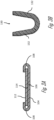
Fig. 7 is a top plan view of a terminal preform used for forming the electrical connector in accordance with the third embodiment of the invention. - Reference numbers of similar elements in the various embodiments share the last two digits of the reference number.
- Examples of electrical terminals that may be soldered to a conductive material applied to a glass surface of an automotive to provide electrical communication with an electrical device, such as an antenna or defroster formed on or in the glass, so that the electrical device may be electrically connected to associated equipment by an electrical cable are presented herein and illustrated in
Figs. 1-5B . A method of forming such an electrical terminal is also presented herein and illustrated inFigs. 6 and7 . The electrical terminal, hereinafter referred to as the terminal 100, includes aplanar base portion 102 having a base portionouter surface 104, a base portioninner surface 106, and two securingtabs 108 extending from an edge of thebase portion 102. The terminal 100 also includes aplanar attachment portion 110 having an attachment portionouter surface 112, an attachment portioninner surface 114, and anattachment member 116 extending from the attachment portionouter surface 112. Theattachment member 116 is configured to secure a wire cable (not shown). The base portioninner surface 106 is arranged such that it is in contact with the attachment portioninner surface 114 and the two securingtabs 108 are bent over the attachment portionouter surface 112. The securing tabs are arranged in opposition to one another. According to a first example of the terminal 100 shown inFigs. 1-4F , the securing tables are offset by about 180° and a width dimension of each of the two securingtabs 108 is equal to 25% or more of a circumferential dimension of thebase portion 102. According to a second example of the terminal 200 shown inFigs. 5A and 5B , thebase portion 202 defines four securingtabs 208 that are offset from one another by about 90° configured to secure thebase portion 202 to theattachment portion 210. Similarly toterminal 100, thebase portion 202 is connected to theattachment portion 210 by a U-shaped strap or connectingmember 234 extending from thebase portion 202 to the attachment portions and integrally formed with thebase portion 202 andattachment portion 210. The width dimension of each of the four securingtabs 208 is less than 25% of the circumferential dimension of thebase portion 202. In alternative embodiments of the terminal, the base portion may be attached to the attachment portion by other means, e.g. welding or electrically conductive adhesive. - The terminal 100 is formed of sheet metal and has a generally curved outer perimeter or edge. The
base portion 102 has a firstcurved perimeter 118 that is generally circular in shape. Theattachment portion 110 has a secondcurved perimeter 120 that is also generally circular in shape. A first diameter of thebase portion 102 is greater than a second diameter of theattachment portion 110. The base portionouter surface 104 may be pre-coated with a layer of solder for facilitating the soldering process. - The
attachment member 116 extends beyond the outer perimeter of theattachment portion 110 and is configured to crimp the terminal 100 to a wire electrical cable. Theslots 122 extend from the outer perimeter of theattachment portion 110, inwardly about halfway to the center line of theattachment portion 110, thereby forming two wings thereof. Theattachment member 116 has anintermediate portion 124 which is bent upwardly at an angle from theproximal end 126 at about the outer perimeter. Thedistal end 128 of theattachment member 116 includes a crimpingportion 130 having two opposed crimpingtabs 132 for crimping to an inner conductor wire of the cable (not shown). Theattachment member 116 is bent between theintermediate portion 124 and thedistal end 128 so that thedistal end 128 is positioned parallel to and laterally offset from theattachment portion 110 as well as above the attachment portionouter surface 112. - The
base portion 102 is integrally formed with theattachment portion 110. Thebase portion 102 is connected to theattachment portion 110 by a U-shaped strap or connectingmember 134 extending from thebase portion 102 to the attachment portions and integrally formed with thebase portion 102 andattachment portion 110. - In use, the terminal 100 is typically soldered to a glass substrate. The
base portion 102 is generally circular in shape and does not tend to cause heat related stress concentrations in glass, and therefore, little or no cracking occurs during the soldering process. Theproximal end 126 of theattachment member 116 extends from theattachment portion 110 and so does not interrupt the circular shape ofbase portion 102. Once soldered, any accidental pulling forces on cable are transferred to the center ofbase portion 102 because theproximal end 126 of theattachment member 116 extends therefrom. Consequently, the terminal 100 is resistant to being separated from glass. - The
base portion 102 andattachment portion 110 are sized, shaped, and arranged such that forces exerted on theattachment member 116 by the wire cable are laterally distributed across thebase portion 102. In addition, the upwardly angledintermediate portion 124 of theattachment member 116 is able to bend or deflect thereby absorbing forces exerted on the terminal 100 by cable. This may lessen the intensity of forces exerted on thebase portion 102 by accidental pulling of the cable. For example, if a longitudinal pulling force is exerted on the cable,intermediate portion 124 would bend slightly to the left and absorb some of the force. In addition, if an upward pulling force is exerted on the cable,intermediate portion 124 would bend slightly upwardly and absorb some of the force. The angledintermediate portion 124 is also able to absorb forces that are forwardly and downwardly directed forces. Furthermore, theproximal end 126 of theattachment member 116 may also bend or deflect to absorb forces. - According to one example, the terminal 100 is formed of C260 brass, the
base portion 102 is about 9 mm in diameter, and the terminal 100 is about 13 mm in length. Alternately, the terminal 100 may be formed of other conductive sheet materials. Theintermediate portion 124 is bent at about a 45° angle to provide equal force absorbing capabilities for longitudinal and vertical forces. The dimensions ofterminal 100 may be varied to suit particular circumstances. Althoughintermediate portion 124 is preferably bent, alternatively, theintermediate portion 124 may be straight. In addition, theproximal end 126 may be bent instead of theintermediate portion 124. - The terminal 100 is formed by a stamping and forming
process 300 from aterminal preform 400. The terminal preforms 400 may be attached to acarrier strip 444 byseverable regions 446 extending from the crimpingportion 130 of theattachment member 416 or the connecting member 430 to facilitate handling and processing of multiple terminals. Thecarrier strip 444 may be cut into to form a multiple terminal soldering assembly, so that multiple terminals may be soldered to glass at the same time. Cables may be crimped to terminals before soldering. - A method or
process 300 of forming theterminals Fig. 6 and is described below: -
STEP 336, PROVIDE A SHEET METAL TERMINAL PREFORM HAVING A TOP SURFACE AND A BOTTOM SURFACE FORMING A BASE PORTION WITH TWO SECURING TABS EXTENDING FROM AN EDGE OF THE BASE PORTION, AN ATTACHMENT PORTION WITH AN ATTACHMENT MEMBER CONFIGURED TO SECURE A WIRE CABLE TO THE ELECTRICAL TERMINAL EXTENDING THEREFROM, AND A CONNECTING MEMBER INTERCONNECTING THE BASE PORTION WITH THE ATTACHMENT PORTION, includes providing aterminal preform 400, as shown inFig. 7 , having atop surface 440 and abottom surface 442 forming abase portion 402 with two securingtabs 408 extending from an edge of thebase portion 402, anattachment portion 410 with anattachment member 416 configured to secure a wire cable to the electrical terminal extending therefrom, and a connectingmember 434 interconnecting thebase portion 402 with theattachment portion 410. Theterminal preform 400 is formed from sheet metal using conventional sheet metal cutting processes, such as stamping, blanking, or cutting; -
STEP 338, BEND THE CONNECTING MEMBER INTO A U-SHAPE SUCH THAT THE BOTTOM SURFACE OF THE BASE PORTION IS IN CONTACT WITH THE BOTTOM SURFACE OF THE ATTACHMENT PORTION, includes bending the connecting member into a U-shape such that the baseportion bottom surface 406 is in contact with the attachmentportion bottom surface 414; and -
STEP 340, BEND THE TWO SECURING TABS SUCH THAT THEY ARE BENT OVER THE ATTACHMENT PORTION TOP SURFACE, includes bending the two securingtabs 408 such that they are bent over the attachment portiontop surface 412, thereby securing thebase portion 402 to theattachment portion 410. - Accordingly,
terminals method 300 of formingsuch terminals terminals base portion base portion
Claims (11)
- An electrical terminal (100) configured to be soldered to a conductive material applied to a glass surface, comprising:a planar base portion (102) having a base portion outer surface (104), a base portion inner surface (106), and two securing tabs (108) extending from an edge of the planar base portion (102), wherein the planar base portion (102) has a first curved perimeter (118) that is generally circular in shape and has a first diameter; characterised in that it further comprisesa planar attachment portion (110) having an attachment portion outer surface (112) and an attachment portion inner surface (114), wherein the planar attachment portion (110) has a second curved perimeter (120) that is generally circular in shape and has a second diameter, and wherein the first diameter of the planar base portion (102) is greater than the second diameter of the planar attachment portion (110), wherein the base portion inner surface (106) is in contact with the attachment portion inner surface (114) and wherein the two securing tabs (108) are bent and overlay the attachment portion outer surface (112).
- The electrical terminal (100) in accordance with claim 1, wherein the planar base portion (102) is integrally formed with the planar attachment portion (110) and wherein the planar base portion (102) is connected to the planar attachment portion (110) by a U-shaped connecting member (134).
- The electrical terminal (100) in accordance with any one of the preceding claims, wherein the planar attachment portion (110) comprises an arm that is configured to secure the electrical terminal (100) to a wire cable.
- The electrical terminal (100) in accordance with claim 3, wherein the arm is deformed to secure the electrical terminal (100) to the wire cable.
- The electrical terminal (100) in accordance with any one of the preceding claims, wherein the two securing tabs (108) are arranged in opposition to one another.
- The electrical terminal (100) in accordance with any one of the preceding claims, wherein a width dimension of each of the two securing tabs (108) is equal to 25% or more of a circumferential dimension of the planar base portion (102).
- A method (300) of forming an electrical terminal (100) configured to be soldered to a conductive material applied to a glass surface, comprising the steps of:providing (336) a sheet metal terminal preform (400) having a top surface (440) and a bottom surface (442);forming a planar base portion (402) with two securing tabs (408) extending from an edge of the base portion (402), a planar attachment portion (410), and a connecting member (434) interconnecting the planar base portion (402) with the planar attachment portion (410), wherein the planar base portion (402) has a first curved perimeter that is generally circular in shape and has a first diameter, wherein the planar attachment portion (410) has a second curved perimeter that is generally circular in shape and has a second diameter, and wherein the first diameter of the planar base portion (402) is greater than the second diameter of the planar attachment portion (410);bending (338) the connecting member (434) into a U-shape such that the bottom surface (406) of the planar base portion (402) is in contact with the bottom surface (414) of the planar attachment portion (410); andbending (340) the two securing tabs (408) such that they overlay the attachment portion top surface (412).
- The method (300) in accordance with claim 7, wherein the attachment member (416) comprises an arm that extends from the planar attachment portion (410).
- The method (300) in accordance with claim 8, further comprising the step of deforming the arm to secure the electrical terminal (100) to the wire cable.
- The method (300) in accordance with any one of the claims 7 to 9, wherein the two securing tabs (408) are arranged in opposition to one another.
- The method (300) in accordance with any one of the claims 7 to 10, wherein a width dimension of each of the two securing tabs (408) is equal to 25% or more of a circumferential dimension of the planar base portion (402).
Applications Claiming Priority (2)
| Application Number | Priority Date | Filing Date | Title |
|---|---|---|---|
| US16/783,253 US10840611B1 (en) | 2020-02-06 | 2020-02-06 | Electrical terminal and method of forming same |
| US17/064,918 US11271329B2 (en) | 2020-02-06 | 2020-10-07 | Electrical terminal and method of forming same |
Publications (2)
| Publication Number | Publication Date |
|---|---|
| EP3863119A1 EP3863119A1 (en) | 2021-08-11 |
| EP3863119B1 true EP3863119B1 (en) | 2025-05-07 |
Family
ID=74505078
Family Applications (1)
| Application Number | Title | Priority Date | Filing Date |
|---|---|---|---|
| EP21154739.3A Active EP3863119B1 (en) | 2020-02-06 | 2021-02-02 | Electrical terminal and method of forming same |
Country Status (3)
| Country | Link |
|---|---|
| US (1) | US11271329B2 (en) |
| EP (1) | EP3863119B1 (en) |
| CN (1) | CN113224569B (en) |
Families Citing this family (1)
| Publication number | Priority date | Publication date | Assignee | Title |
|---|---|---|---|---|
| KR102855781B1 (en) | 2021-06-15 | 2025-09-05 | 주식회사 엘지에너지솔루션 | A Battery Module With A Curved Trap Part And A Battery Pack Containing It |
Family Cites Families (21)
| Publication number | Priority date | Publication date | Assignee | Title |
|---|---|---|---|---|
| US3188600A (en) * | 1960-09-12 | 1965-06-08 | Gen Motors Corp | Terminal and mounting means |
| US3644872A (en) * | 1970-10-22 | 1972-02-22 | Gen Motors Corp | Hermaphroditic terminal |
| GB1490195A (en) * | 1973-12-28 | 1977-10-26 | Rists Wires & Cables Ltd | Electrical terminals |
| GB1463751A (en) * | 1974-05-03 | 1977-02-09 | Amp Inc | Electrical tab receptacle |
| US4558913A (en) * | 1982-05-18 | 1985-12-17 | Fujikura Ltd. | Electrical connector |
| US4951389A (en) | 1989-05-31 | 1990-08-28 | Amp Incorporated | Method for making a wire barrel terminal |
| JP3159073B2 (en) * | 1996-08-08 | 2001-04-23 | 住友電装株式会社 | Terminal fitting and manufacturing method thereof |
| US5980338A (en) * | 1997-08-15 | 1999-11-09 | Molex Incorporated | Low profile female terminal for mating to a post-like male terminal |
| US6331742B1 (en) * | 1998-12-31 | 2001-12-18 | General Electric Company | Electric motor connector module |
| US6267630B1 (en) | 1999-08-04 | 2001-07-31 | Antaya Technologies Corporation | Circular connector with blade terminal |
| US6406337B1 (en) | 2000-09-27 | 2002-06-18 | Antaya Technologies Corporation | Glass mounted electrical terminal |
| ES2540735T3 (en) * | 2008-07-29 | 2015-07-13 | Saint-Gobain Glass France | Female electrical connector and connection using this female electrical connector |
| US8485853B2 (en) * | 2011-11-03 | 2013-07-16 | Delphi Technologies, Inc. | Electrical contact having knurl pattern with recessed rhombic elements that each have an axial minor distance |
| KR101728256B1 (en) | 2012-09-14 | 2017-04-18 | 쌩-고벵 글래스 프랑스 | Pane having an electrical connection element |
| KR20160039191A (en) | 2013-07-31 | 2016-04-08 | 안타야 테크놀로지스 코포레이션 | Electrical component having presoldered surface with flux reservoirs |
| JP6014075B2 (en) * | 2014-04-17 | 2016-10-25 | ヒロセ電機株式会社 | Electrical connector assembly |
| JP2016091772A (en) | 2014-11-04 | 2016-05-23 | 株式会社オートネットワーク技術研究所 | Bus bar |
| KR20160101652A (en) * | 2015-02-17 | 2016-08-25 | 타이코에이엠피 주식회사 | Connecting terminal and circuit board module comprising thereof |
| US10446950B2 (en) * | 2017-06-26 | 2019-10-15 | Delphi Technologies, Llc | Method for forming a shielded electrical terminal and an electrical terminal formed by said method |
| CN209150309U (en) * | 2018-12-19 | 2019-07-23 | 乐清市合达电子有限公司 | A kind of vehicle glass connecting terminal |
| US10840611B1 (en) * | 2020-02-06 | 2020-11-17 | Aptive Technologies Limited | Electrical terminal and method of forming same |
-
2020
- 2020-10-07 US US17/064,918 patent/US11271329B2/en active Active
- 2020-12-29 CN CN202011592003.0A patent/CN113224569B/en active Active
-
2021
- 2021-02-02 EP EP21154739.3A patent/EP3863119B1/en active Active
Also Published As
| Publication number | Publication date |
|---|---|
| EP3863119A1 (en) | 2021-08-11 |
| US11271329B2 (en) | 2022-03-08 |
| CN113224569B (en) | 2023-05-23 |
| CN113224569A (en) | 2021-08-06 |
| US20210249792A1 (en) | 2021-08-12 |
Similar Documents
| Publication | Publication Date | Title |
|---|---|---|
| US6406337B1 (en) | Glass mounted electrical terminal | |
| US10840611B1 (en) | Electrical terminal and method of forming same | |
| EP0767514B1 (en) | One-piece hooded socket contact and method of producing same | |
| US10292256B2 (en) | Pane with an electrical connection element | |
| US9711872B2 (en) | Crimp terminal and structure for connecting crimp terminal and wire | |
| EP2309599B1 (en) | Terminal clamp and wire with terminal clamp | |
| US9379458B2 (en) | Electrical connector element | |
| US5897406A (en) | Electrical terminal for glass sheets | |
| US20160126642A1 (en) | Terminal, crimp terminal, wire harness, and method for manufacturing crimp terminal | |
| EP3582332B1 (en) | Connection terminal and terminal connection structure | |
| JPH05152011A (en) | Crimp-style terminal | |
| US20180090900A1 (en) | Method for manufacturing female terminal and female terminal | |
| US20040224576A1 (en) | Male terminal fitting and method of manufacturing the same | |
| EP0635904A2 (en) | Electrical terminal for use with short circuit spring contacts | |
| JPH07502137A (en) | Dual-use electrical/electronic pin terminal system | |
| US6261134B1 (en) | One-piece hooded socket contact and method of producing same | |
| US11271329B2 (en) | Electrical terminal and method of forming same | |
| EP0568927A1 (en) | Electrical socket terminal | |
| CN116581611A (en) | Axial cable terminal with two-piece crimped outer ferrule | |
| CN108701909B (en) | Solderable electrical connection elements | |
| EP2602875B1 (en) | Crimp terminal | |
| EP0898339A2 (en) | Female terminal | |
| US20190199007A1 (en) | Wire with terminal | |
| GB2153162A (en) | Improvements in or relating to electrical connectors | |
| CN114400460A (en) | a terminal |
Legal Events
| Date | Code | Title | Description |
|---|---|---|---|
| PUAI | Public reference made under article 153(3) epc to a published international application that has entered the european phase |
Free format text: ORIGINAL CODE: 0009012 |
|
| STAA | Information on the status of an ep patent application or granted ep patent |
Free format text: STATUS: THE APPLICATION HAS BEEN PUBLISHED |
|
| AK | Designated contracting states |
Kind code of ref document: A1 Designated state(s): AL AT BE BG CH CY CZ DE DK EE ES FI FR GB GR HR HU IE IS IT LI LT LU LV MC MK MT NL NO PL PT RO RS SE SI SK SM TR |
|
| STAA | Information on the status of an ep patent application or granted ep patent |
Free format text: STATUS: REQUEST FOR EXAMINATION WAS MADE |
|
| 17P | Request for examination filed |
Effective date: 20220204 |
|
| RBV | Designated contracting states (corrected) |
Designated state(s): AL AT BE BG CH CY CZ DE DK EE ES FI FR GB GR HR HU IE IS IT LI LT LU LV MC MK MT NL NO PL PT RO RS SE SI SK SM TR |
|
| RAP3 | Party data changed (applicant data changed or rights of an application transferred) |
Owner name: APTIV TECHNOLOGIES LIMITED |
|
| STAA | Information on the status of an ep patent application or granted ep patent |
Free format text: STATUS: EXAMINATION IS IN PROGRESS |
|
| 17Q | First examination report despatched |
Effective date: 20230613 |
|
| RAP1 | Party data changed (applicant data changed or rights of an application transferred) |
Owner name: APTIV TECHNOLOGIES AG |
|
| RAP3 | Party data changed (applicant data changed or rights of an application transferred) |
Owner name: APTIV TECHNOLOGIES AG |
|
| GRAP | Despatch of communication of intention to grant a patent |
Free format text: ORIGINAL CODE: EPIDOSNIGR1 |
|
| STAA | Information on the status of an ep patent application or granted ep patent |
Free format text: STATUS: GRANT OF PATENT IS INTENDED |
|
| RIC1 | Information provided on ipc code assigned before grant |
Ipc: H01R 4/02 20060101ALN20241216BHEP Ipc: H05B 3/84 20060101ALN20241216BHEP Ipc: H05B 3/08 20060101ALN20241216BHEP Ipc: H01Q 1/12 20060101ALN20241216BHEP Ipc: H01R 12/57 20110101ALI20241216BHEP Ipc: H01R 12/53 20110101ALI20241216BHEP Ipc: H05B 3/06 20060101ALI20241216BHEP Ipc: H01R 43/16 20060101ALI20241216BHEP Ipc: H01R 11/16 20060101ALI20241216BHEP Ipc: H01R 4/18 20060101AFI20241216BHEP |
|
| INTG | Intention to grant announced |
Effective date: 20250110 |
|
| P01 | Opt-out of the competence of the unified patent court (upc) registered |
Free format text: CASE NUMBER: APP_2193/2025 Effective date: 20250114 |
|
| GRAS | Grant fee paid |
Free format text: ORIGINAL CODE: EPIDOSNIGR3 |
|
| GRAA | (expected) grant |
Free format text: ORIGINAL CODE: 0009210 |
|
| STAA | Information on the status of an ep patent application or granted ep patent |
Free format text: STATUS: THE PATENT HAS BEEN GRANTED |
|
| AK | Designated contracting states |
Kind code of ref document: B1 Designated state(s): AL AT BE BG CH CY CZ DE DK EE ES FI FR GB GR HR HU IE IS IT LI LT LU LV MC MK MT NL NO PL PT RO RS SE SI SK SM TR |
|
| REG | Reference to a national code |
Ref country code: GB Ref legal event code: FG4D |
|
| REG | Reference to a national code |
Ref country code: CH Ref legal event code: EP |
|
| REG | Reference to a national code |
Ref country code: DE Ref legal event code: R096 Ref document number: 602021030218 Country of ref document: DE |
|
| REG | Reference to a national code |
Ref country code: IE Ref legal event code: FG4D |
|
| REG | Reference to a national code |
Ref country code: NL Ref legal event code: MP Effective date: 20250507 |
|
| PG25 | Lapsed in a contracting state [announced via postgrant information from national office to epo] |
Ref country code: PT Free format text: LAPSE BECAUSE OF FAILURE TO SUBMIT A TRANSLATION OF THE DESCRIPTION OR TO PAY THE FEE WITHIN THE PRESCRIBED TIME-LIMIT Effective date: 20250908 Ref country code: FI Free format text: LAPSE BECAUSE OF FAILURE TO SUBMIT A TRANSLATION OF THE DESCRIPTION OR TO PAY THE FEE WITHIN THE PRESCRIBED TIME-LIMIT Effective date: 20250507 Ref country code: ES Free format text: LAPSE BECAUSE OF FAILURE TO SUBMIT A TRANSLATION OF THE DESCRIPTION OR TO PAY THE FEE WITHIN THE PRESCRIBED TIME-LIMIT Effective date: 20250507 |
|
| REG | Reference to a national code |
Ref country code: LT Ref legal event code: MG9D |
|
| PG25 | Lapsed in a contracting state [announced via postgrant information from national office to epo] |
Ref country code: NO Free format text: LAPSE BECAUSE OF FAILURE TO SUBMIT A TRANSLATION OF THE DESCRIPTION OR TO PAY THE FEE WITHIN THE PRESCRIBED TIME-LIMIT Effective date: 20250807 Ref country code: GR Free format text: LAPSE BECAUSE OF FAILURE TO SUBMIT A TRANSLATION OF THE DESCRIPTION OR TO PAY THE FEE WITHIN THE PRESCRIBED TIME-LIMIT Effective date: 20250808 |
|
| PG25 | Lapsed in a contracting state [announced via postgrant information from national office to epo] |
Ref country code: NL Free format text: LAPSE BECAUSE OF FAILURE TO SUBMIT A TRANSLATION OF THE DESCRIPTION OR TO PAY THE FEE WITHIN THE PRESCRIBED TIME-LIMIT Effective date: 20250507 Ref country code: PL Free format text: LAPSE BECAUSE OF FAILURE TO SUBMIT A TRANSLATION OF THE DESCRIPTION OR TO PAY THE FEE WITHIN THE PRESCRIBED TIME-LIMIT Effective date: 20250507 |
|
| REG | Reference to a national code |
Ref country code: AT Ref legal event code: MK05 Ref document number: 1793560 Country of ref document: AT Kind code of ref document: T Effective date: 20250507 |
|
| PG25 | Lapsed in a contracting state [announced via postgrant information from national office to epo] |
Ref country code: BG Free format text: LAPSE BECAUSE OF FAILURE TO SUBMIT A TRANSLATION OF THE DESCRIPTION OR TO PAY THE FEE WITHIN THE PRESCRIBED TIME-LIMIT Effective date: 20250507 |
|
| PG25 | Lapsed in a contracting state [announced via postgrant information from national office to epo] |
Ref country code: HR Free format text: LAPSE BECAUSE OF FAILURE TO SUBMIT A TRANSLATION OF THE DESCRIPTION OR TO PAY THE FEE WITHIN THE PRESCRIBED TIME-LIMIT Effective date: 20250507 |
|
| PG25 | Lapsed in a contracting state [announced via postgrant information from national office to epo] |
Ref country code: AT Free format text: LAPSE BECAUSE OF FAILURE TO SUBMIT A TRANSLATION OF THE DESCRIPTION OR TO PAY THE FEE WITHIN THE PRESCRIBED TIME-LIMIT Effective date: 20250507 |
|
| PG25 | Lapsed in a contracting state [announced via postgrant information from national office to epo] |
Ref country code: RS Free format text: LAPSE BECAUSE OF FAILURE TO SUBMIT A TRANSLATION OF THE DESCRIPTION OR TO PAY THE FEE WITHIN THE PRESCRIBED TIME-LIMIT Effective date: 20250807 |
|
| PG25 | Lapsed in a contracting state [announced via postgrant information from national office to epo] |
Ref country code: IS Free format text: LAPSE BECAUSE OF FAILURE TO SUBMIT A TRANSLATION OF THE DESCRIPTION OR TO PAY THE FEE WITHIN THE PRESCRIBED TIME-LIMIT Effective date: 20250907 |
|
| PG25 | Lapsed in a contracting state [announced via postgrant information from national office to epo] |
Ref country code: LV Free format text: LAPSE BECAUSE OF FAILURE TO SUBMIT A TRANSLATION OF THE DESCRIPTION OR TO PAY THE FEE WITHIN THE PRESCRIBED TIME-LIMIT Effective date: 20250507 |
|
| PG25 | Lapsed in a contracting state [announced via postgrant information from national office to epo] |
Ref country code: SM Free format text: LAPSE BECAUSE OF FAILURE TO SUBMIT A TRANSLATION OF THE DESCRIPTION OR TO PAY THE FEE WITHIN THE PRESCRIBED TIME-LIMIT Effective date: 20250507 Ref country code: DK Free format text: LAPSE BECAUSE OF FAILURE TO SUBMIT A TRANSLATION OF THE DESCRIPTION OR TO PAY THE FEE WITHIN THE PRESCRIBED TIME-LIMIT Effective date: 20250507 |
|
| PG25 | Lapsed in a contracting state [announced via postgrant information from national office to epo] |
Ref country code: CZ Free format text: LAPSE BECAUSE OF FAILURE TO SUBMIT A TRANSLATION OF THE DESCRIPTION OR TO PAY THE FEE WITHIN THE PRESCRIBED TIME-LIMIT Effective date: 20250507 |
|
| PG25 | Lapsed in a contracting state [announced via postgrant information from national office to epo] |
Ref country code: EE Free format text: LAPSE BECAUSE OF FAILURE TO SUBMIT A TRANSLATION OF THE DESCRIPTION OR TO PAY THE FEE WITHIN THE PRESCRIBED TIME-LIMIT Effective date: 20250507 |
|
| PG25 | Lapsed in a contracting state [announced via postgrant information from national office to epo] |
Ref country code: RO Free format text: LAPSE BECAUSE OF FAILURE TO SUBMIT A TRANSLATION OF THE DESCRIPTION OR TO PAY THE FEE WITHIN THE PRESCRIBED TIME-LIMIT Effective date: 20250507 Ref country code: SK Free format text: LAPSE BECAUSE OF FAILURE TO SUBMIT A TRANSLATION OF THE DESCRIPTION OR TO PAY THE FEE WITHIN THE PRESCRIBED TIME-LIMIT Effective date: 20250507 |
|
| PG25 | Lapsed in a contracting state [announced via postgrant information from national office to epo] |
Ref country code: IT Free format text: LAPSE BECAUSE OF FAILURE TO SUBMIT A TRANSLATION OF THE DESCRIPTION OR TO PAY THE FEE WITHIN THE PRESCRIBED TIME-LIMIT Effective date: 20250507 |
|
| REG | Reference to a national code |
Ref country code: DE Ref legal event code: R097 Ref document number: 602021030218 Country of ref document: DE |
|
| PLBE | No opposition filed within time limit |
Free format text: ORIGINAL CODE: 0009261 |
|
| STAA | Information on the status of an ep patent application or granted ep patent |
Free format text: STATUS: NO OPPOSITION FILED WITHIN TIME LIMIT |
|
| REG | Reference to a national code |
Ref country code: CH Ref legal event code: L10 Free format text: ST27 STATUS EVENT CODE: U-0-0-L10-L00 (AS PROVIDED BY THE NATIONAL OFFICE) Effective date: 20260318 |
|
| PGFP | Annual fee paid to national office [announced via postgrant information from national office to epo] |
Ref country code: GB Payment date: 20260113 Year of fee payment: 6 |
|
| PGFP | Annual fee paid to national office [announced via postgrant information from national office to epo] |
Ref country code: DE Payment date: 20260121 Year of fee payment: 6 |
|
| 26N | No opposition filed |
Effective date: 20260210 |
|
| PGFP | Annual fee paid to national office [announced via postgrant information from national office to epo] |
Ref country code: FR Payment date: 20260109 Year of fee payment: 6 |