EP3862989B1 - Projectors, projector systems and methods of navigating terrain using projected images - Google Patents
Projectors, projector systems and methods of navigating terrain using projected images Download PDFInfo
- Publication number
- EP3862989B1 EP3862989B1 EP21155589.1A EP21155589A EP3862989B1 EP 3862989 B1 EP3862989 B1 EP 3862989B1 EP 21155589 A EP21155589 A EP 21155589A EP 3862989 B1 EP3862989 B1 EP 3862989B1
- Authority
- EP
- European Patent Office
- Prior art keywords
- projector
- terrain
- navigation feature
- optical axis
- image
- Prior art date
- Legal status (The legal status is an assumption and is not a legal conclusion. Google has not performed a legal analysis and makes no representation as to the accuracy of the status listed.)
- Active
Links
Images





Classifications
-
- G—PHYSICS
- G01—MEASURING; TESTING
- G01C—MEASURING DISTANCES, LEVELS OR BEARINGS; SURVEYING; NAVIGATION; GYROSCOPIC INSTRUMENTS; PHOTOGRAMMETRY OR VIDEOGRAMMETRY
- G01C21/00—Navigation; Navigational instruments not provided for in groups G01C1/00 - G01C19/00
- G01C21/20—Instruments for performing navigational calculations
-
- G—PHYSICS
- G02—OPTICS
- G02B—OPTICAL ELEMENTS, SYSTEMS OR APPARATUS
- G02B27/00—Optical systems or apparatus not provided for by any of the groups G02B1/00 - G02B26/00, G02B30/00
- G02B27/01—Head-up displays
- G02B27/017—Head mounted
- G02B27/0172—Head mounted characterised by optical features
-
- G—PHYSICS
- G03—PHOTOGRAPHY; CINEMATOGRAPHY; ANALOGOUS TECHNIQUES USING WAVES OTHER THAN OPTICAL WAVES; ELECTROGRAPHY; HOLOGRAPHY
- G03B—APPARATUS OR ARRANGEMENTS FOR TAKING PHOTOGRAPHS OR FOR PROJECTING OR VIEWING THEM; APPARATUS OR ARRANGEMENTS EMPLOYING ANALOGOUS TECHNIQUES USING WAVES OTHER THAN OPTICAL WAVES; ACCESSORIES THEREFOR
- G03B21/00—Projectors or projection-type viewers; Accessories therefor
- G03B21/14—Details
- G03B21/20—Lamp housings
- G03B21/2006—Lamp housings characterised by the light source
- G03B21/2033—LED or laser light sources
-
- G—PHYSICS
- G06—COMPUTING OR CALCULATING; COUNTING
- G06T—IMAGE DATA PROCESSING OR GENERATION, IN GENERAL
- G06T3/00—Geometric image transformations in the plane of the image
- G06T3/08—Projecting images onto non-planar surfaces, e.g. geodetic screens
-
- G—PHYSICS
- G06—COMPUTING OR CALCULATING; COUNTING
- G06V—IMAGE OR VIDEO RECOGNITION OR UNDERSTANDING
- G06V20/00—Scenes; Scene-specific elements
- G06V20/20—Scenes; Scene-specific elements in augmented reality scenes
-
- H—ELECTRICITY
- H04—ELECTRIC COMMUNICATION TECHNIQUE
- H04N—PICTORIAL COMMUNICATION, e.g. TELEVISION
- H04N9/00—Details of colour television systems
- H04N9/12—Picture reproducers
- H04N9/31—Projection devices for colour picture display, e.g. using electronic spatial light modulators [ESLM]
- H04N9/3141—Constructional details thereof
- H04N9/315—Modulator illumination systems
- H04N9/3161—Modulator illumination systems using laser light sources
-
- H—ELECTRICITY
- H04—ELECTRIC COMMUNICATION TECHNIQUE
- H04N—PICTORIAL COMMUNICATION, e.g. TELEVISION
- H04N9/00—Details of colour television systems
- H04N9/12—Picture reproducers
- H04N9/31—Projection devices for colour picture display, e.g. using electronic spatial light modulators [ESLM]
- H04N9/3179—Video signal processing therefor
- H04N9/3182—Colour adjustment, e.g. white balance, shading or gamut
-
- H—ELECTRICITY
- H04—ELECTRIC COMMUNICATION TECHNIQUE
- H04N—PICTORIAL COMMUNICATION, e.g. TELEVISION
- H04N9/00—Details of colour television systems
- H04N9/12—Picture reproducers
- H04N9/31—Projection devices for colour picture display, e.g. using electronic spatial light modulators [ESLM]
- H04N9/3179—Video signal processing therefor
- H04N9/3185—Geometric adjustment, e.g. keystone or convergence
-
- G—PHYSICS
- G01—MEASURING; TESTING
- G01B—MEASURING LENGTH, THICKNESS OR SIMILAR LINEAR DIMENSIONS; MEASURING ANGLES; MEASURING AREAS; MEASURING IRREGULARITIES OF SURFACES OR CONTOURS
- G01B11/00—Measuring arrangements characterised by the use of optical techniques
- G01B11/24—Measuring arrangements characterised by the use of optical techniques for measuring contours or curvatures
- G01B11/25—Measuring arrangements characterised by the use of optical techniques for measuring contours or curvatures by projecting a pattern, e.g. one or more lines, moiré fringes on the object
- G01B11/2513—Measuring arrangements characterised by the use of optical techniques for measuring contours or curvatures by projecting a pattern, e.g. one or more lines, moiré fringes on the object with several lines being projected in more than one direction, e.g. grids, patterns
-
- G—PHYSICS
- G01—MEASURING; TESTING
- G01S—RADIO DIRECTION-FINDING; RADIO NAVIGATION; DETERMINING DISTANCE OR VELOCITY BY USE OF RADIO WAVES; LOCATING OR PRESENCE-DETECTING BY USE OF THE REFLECTION OR RERADIATION OF RADIO WAVES; ANALOGOUS ARRANGEMENTS USING OTHER WAVES
- G01S17/00—Systems using the reflection or reradiation of electromagnetic waves other than radio waves, e.g. lidar systems
- G01S17/88—Lidar systems specially adapted for specific applications
- G01S17/89—Lidar systems specially adapted for specific applications for mapping or imaging
-
- G—PHYSICS
- G02—OPTICS
- G02B—OPTICAL ELEMENTS, SYSTEMS OR APPARATUS
- G02B27/00—Optical systems or apparatus not provided for by any of the groups G02B1/00 - G02B26/00, G02B30/00
- G02B27/01—Head-up displays
- G02B27/0101—Head-up displays characterised by optical features
- G02B2027/0118—Head-up displays characterised by optical features comprising devices for improving the contrast of the display / brillance control visibility
- G02B2027/012—Head-up displays characterised by optical features comprising devices for improving the contrast of the display / brillance control visibility comprising devices for attenuating parasitic image effects
-
- G—PHYSICS
- G08—SIGNALLING
- G08G—TRAFFIC CONTROL SYSTEMS
- G08G1/00—Traffic control systems for road vehicles
- G08G1/005—Traffic control systems for road vehicles including pedestrian guidance indicator
Definitions
- the present disclosure is generally related to navigation, and more particularly to navigating terrain where ambient illumination is limited or degraded.
- Navigation devices are commonly employed to assist with navigation in environments with limited and/or degraded illumination.
- navigation devices in terrestrial settings generally have the capability to obtain external data from Wi-Fi systems to provide the user with information to assist in navigation.
- Some navigation devices can also obtain external data from global positioning satellites (GPS) to provide the user with information to assist in navigation.
- GPS global positioning satellites
- Access to such sources of external data typically reduce the risk of injury or accident while navigating environments under conditions of limited or degraded illumination.
- Wi-Fi and/or GPS can be limited, such as due to interruption or absence of the infrastructure required for Wi-Fi and/or GPS communication.
- Wi-Fi and GPS communication is generally unavailable in lunar environments.
- Lunar trekkers are therefore typically unable employ Wi-Fi and GPS-based utilities and must rely upon solar illumination to appreciate features in lunar terrain being traversed to navigate the lunar environment. Since the lunar atmosphere is too thin to sufficiently scatter ambient solar illumination to illuminate features shielded from direct solar illumination, it can be difficult for lunar trekkers to appreciate certain features, e.g., depths of recesses and features in shaded areas. Failure to appreciate such features can increase the risk of injury and/or equipment damage during lunar trekking due to tripping over rises or stumbling over.
- a projector system is defined in claim 1.
- the projector may include that the light source includes a laser arranged to illuminate the navigation feature with laser light.
- the projector may include that the light source includes a visible source arranged to illuminate the navigation feature with visible light.
- further examples of the projector may include that the navigation feature is fixed to the reticle and defines a grid pattern.
- further examples of the projector may include the navigation feature includes an overlay of the terrain disposed within the field of view of the projector.
- further examples of the projector may include a sensor in communication with the terrain disposed within the field of view of the projector.
- further examples of the projector may include that the sensor includes a time-of-flight sensor or a structured light sensor optically coupled to the terrain disposed within the field of view of the projector.
- further examples of the projector may include the projection lens has a slow lens or a laser scanning system.
- further examples of the projector may include an upper torso hard shell having a helmet seat and a shoulder portion, and a helmet fixed to the helmet seat of the upper torso hard shell, wherein the projector is coupled to the shoulder portion of the upper torso hard shell.
- further examples of the projector may include that the projector is fixed relative to the helmet.
- further examples of the projector may include a stabilization module coupled to the projector and arranged to allow the upper torso hard shell to move relative to the projector while the projector is fixed relative to the terrain disposed within the field of view of the projector.
- further examples of the projector may include a shifting element arranged to bypass the navigation feature with light communicated by the light source.
- a projector system is also provided.
- the projector system includes a projector as described above and a controller.
- the reticle includes a micro display arranged on the reticle and arranged along the optical axis.
- the controller is operably connected to the micro display and responsive to instructions recorded on a non-transitory machine-readable memory to illuminate the navigation feature with light source illumination to generate a navigation feature image, project the navigation feature image into the field of view of the projector with the projection lens, and display the navigation feature image on the terrain disposed within the field of the projection lens.
- further examples of the projector system may include the instructions further cause the controller to select a color for the at least one of a grid pattern, a water or ice tag, a mineral tag, and an overlay of terrain disposed along the optical axis with the micro display; illuminate the micro display with light having the selected color; and display the at least one of a grid pattern, a water or ice tag, a mineral tag, and an overlay of the terrain disposed along the optical axis on the terrain disposed along the optical axis with the selected color.
- further examples of the projector system may include a time-of-flight sensor or a structured light sensor disposed in communication with the controller and having a field of view intersecting the optical axis of the projector, and that the instructions cause the controller to acquire image data of the terrain disposed along the optical axis; and reconstruct an image of the terrain with the micro display; and project the image of the terrain by illuminating the micro display with the light source for display on the terrain from the which the image data was acquired.
- a time-of-flight sensor or a structured light sensor disposed in communication with the controller and having a field of view intersecting the optical axis of the projector, and that the instructions cause the controller to acquire image data of the terrain disposed along the optical axis; and reconstruct an image of the terrain with the micro display; and project the image of the terrain by illuminating the micro display with the light source for display on the terrain from the which the image data was acquired.
- further examples of the projector system may include that reconstructing the image includes distorting the image for conformal display on the terrain disposed along the optical axis.
- further examples of the projector system may include that the instructions further cause the controller to generate a one or more of a predetermined map, a predetermined schematic, and a predetermined procedure with the micro display; and project an image of the one or more of a predetermined map, a predetermined schematic, and a predetermined procedure along the optical axis with the light source.
- a navigation method includes, at a projector as described above, illuminating the navigation feature with light source illumination to generate a navigation feature image, projecting the navigation feature image into a field of view of the projector with the projection lens, and displaying the navigation feature image on terrain disposed within the field of the projection lens.
- the present disclosure provides the capability to display grid patterns and/or navigation information on terrain negotiated by vehicles.
- a grid is projected from the navigation system and displayed on the terrain in the path of the vehicle.
- the displayed grid conforms to the terrain and provide the vehicle driver, pilot or control system with awareness of the terrain contour.
- the navigation system includes a sensor device.
- the sensor device acquires information regarding the terrain in the path of the vehicle and the navigation system projecting information regarding the terrain for display on the terrain. It is also contemplated that, in accordance with certain examples, that the navigation system also projects light on the terrain in the path of the vehicle to illuminate the vehicle path along the terrain.
- FIG. 1 a partial view of an example of a projector in accordance with the disclosure is shown in FIG. 1 and is designated generally by reference character 100.
- FIGS. 2-8 Other embodiments of projectors, projector systems, and navigation methods are provided in FIGS. 2-8 , as will be described.
- the systems and methods described herein can be used for navigating in environments having limited or degraded illumination, such as while trekking across lunar terrain, though the present disclosure is not limited to lunar trekking or to lunar environments in general.
- the projector 100 generally includes a light source 102 arranged along an optical axis 104, a reticle 106 optically coupled to the light source 102 along the optical axis 104, and a projection lens 108.
- the projection lens 108 is optically coupled to the reticle 106 along the optical axis 104 and defines thereon a navigation feature 110 arranged for generating a navigation feature image 10 for display on the terrain 12 disposed within a field of view 14 of the projector 100.
- the projector 100 also includes a shifting element 112, a user interface 114, a stabilization module 116, and a housing 118.
- the housing 118 has an interior 120 and a mounting feature 122.
- the light source 102, the reticle 106 and the projection lens 108 are arranged within the interior 120 of the housing 118 and are supported along the optical axis 104.
- the mounting feature 122 is arranged on an exterior of the housing 118 and is arranged for fixation of the projector 100 to a vehicle 16.
- the vehicle 16 is an aircraft.
- the vehicle 16 is a terrestrial or marine vehicle. It is also contemplated that projector 100 can be fixed to a space suit or other wearable assembly 18 (shown in FIG. 2 ).
- the light source 102 is configured to illuminate the reticle 106 with light source illumination 20.
- the light source 102 is optically coupled to the reticle 106 along the optical axis 104 to convey the light source illumination 20 along the optical axis 104 to the reticle 106.
- the light source 102 includes a visible light source 124 arranged to communicate visible light along the optical axis 104.
- the light source 102 includes a laser light source 126 arranged to communicate laser light along the optical axis 104.
- the reticle 106 optically couples the projection lens 108 to the light source 102 and defines thereon the navigation feature 110.
- the reticle 106 includes a plate body formed from a transmissive material, e.g., glass, and is arranged to communicate a portion of light source illumination 20 incident upon the reticle 106 according to the projection lens 108 according to shape of the navigation feature 110.
- the navigation feature 110 includes a transmissive portion 128 and an opaque portion 130 arranged to generate the navigation feature image 10 from a portion of the light source illumination 20 transmitted by the transmissive portion 128 of the navigation feature 110.
- the reticle 106 communicates the navigation feature image 10 to the projection lens 108 along the optical axis 104.
- the projection lens 108 is optically coupled to the light source 102 by the optical axis 104 through the reticle 106 and is arranged to project the navigation feature image 10 from the projector 100 along the optical axis 104.
- the projection lens 108 projects the navigation feature image 10 within the field of view 14 of the projector 100 for display of the navigation feature image 10 on the terrain 12.
- the projection lens 108 includes an expansion lens arranged to project the navigation feature image 10 within the field of view 14 of size greater than that of the navigation feature 110.
- the projection lens 108 has an aperture size that cooperates with the navigation feature 110 to provide depth of field sufficient to resolve the navigation feature image 10 in the direction of the horizon bounding the field of view 14, e.g., twenty (20) feet, when the projector 100 is fixed to the user's shoulder.
- the projection lens 108 be a slow lens with a large depth of focus, the projection lens 108 thereby able to maintain good image quality over long distances and over uneven surfaces such as may be found on lunar terrain.
- a laser scanning system can be employed to draw the image within the field of view 14 as an alternative to the projection lens 108.
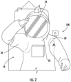
- the projector 100 is shown fixed to the space suit or other wearable assembly 18.
- the space suit or other wearable assembly 18 includes the projector 100, an upper torso hard shell 22 and a helmet 24.
- the upper torso hard shell 22 has a helmet seat 26, a shoulder portion 28, and a projector mount 30.
- the helmet 24 provides a helmet field of view contained with the field of view 14 (shown in FIG. 1 ) of the projector 100, is seated on the helmet seat 26, and is fixed relative to the upper torso hard shell 22.
- the projector 100 is seated on the projector mount 30, e.g., with the mounting feature 122 (shown in FIG. 1 ).
- the projector 100 is fixed relative to the upper torso hard shell 22 by the projector mount 30.
- the stabilization module 116 (shown in FIG. 1 ) is arranged between the mounting feature 122 and the projector mount 30 located on the upper torso hard shell 22 of the space suit or other wearable assembly 18.
- the projector 100 is shown projecting the navigation feature image 10 and displaying the navigation feature image 10 on the terrain 12 according to an example.
- the light source 102 (shown in FIG. 1 ) illuminates the reticle 106 (shown in FIG. 1 ) with the light source illumination 20 (shown in FIG. 1 ).
- the reticle 106 in turn modulates illumination incident upon the reticle 106 according to the navigation feature 110 (shown in FIG. 1 ) and communicates a portion of the light source illumination 20 to the projection lens 108 (shown in FIG. 1 ) as the navigation feature image 10.
- the projection lens 108 projects the navigation feature image 10 into the field of view 14 of the projector 100.
- the terrain 12 disposed within the field of view 14 displays the navigation feature image 10 thereon conformally, the navigation feature image 10 thereby showing contour and shape of the terrain 12 irrespective of whether ambient solar illumination illuminates the terrain 12.
- the projection lens 108 expands the navigation feature image 10 to at least partially fill (or entirely fill) the field of view 14 of the projector 100 for display on the terrain disposed within the field of view 14 of the projector 100.
- the navigation feature image 10 be formed in a way that allows a user, e.g., a user occupying the space suit or other wearable assembly 18, to appreciate features and/or contour 17 on the terrain 12 disposed within the field of view 14 of the projector 100.
- the navigation feature image 10 defines a grid pattern 32 having intersecting grid lines on the terrain 12 such that distortion, e.g., departure from a repetitive pattern, in the grid pattern 32 corresponds to depth and rises in the terrain 12 otherwise difficult (or impossible) to discern using ambient solar illumination.
- the grid pattern 32 is a fixed grid pattern, e.g., fixed according to the transmissive portion 128 (shown in FIG. 1 ) and the opaque portion 130 (shown in FIG. 1 ) of the reticle 106 (shown in FIG. 1 ).
- the user interface 114 when included in the projector 100, the user interface 114 is operably connected to the light source 102 to control the wavelength (or waveband) of the light source illumination 20.
- the user interface 114 is arranged to change color of the light source illumination 20, and thereby the color of the navigation feature image 10 displayed on the terrain 12 according to a user input 34 received at the user interface 114.
- changing the color forming the navigation feature image 10 displayed on the terrain 12 allows a user to select the color of the navigation feature image 10 as appropriate for the specific user negotiating the terrain 12 and/or the properties of ambient solar illumination in the particular lunar environment.
- the shifting element 112 is arranged to route the optical axis 104 around the navigation feature 110 and/or the reticle 106.
- fold mirrors can be employed to route the light source illumination 20 about the navigation feature 110 and/or the reticle 106.
- the reticle 106 can be displaced from the optical axis 104.
- bypassing the navigation feature 110 and/or the reticle 106 allows the projector 100 to illuminate the terrain 12 disposed within the field of view 14 of the projector 100 with unmodulated illumination, the projector 100 thereby operating as a flashlight. This eliminates the need to provision the space suit or other wearable assembly 18 with a general-purpose flashlight in additional to providing the above-described navigational assistance when traversing the terrain 12.
- the stabilization module 116 allows the projector 100 to move relative to the vehicle 16 or the space suit or other wearable assembly 18 (shown in FIG. 2 ).
- the stabilization module 116 is disengaged, the projector 100 is fixed relative to the vehicle 16 or the space suit or other wearable assembly 18 (shown in FIG. 2 ).
- the stabilization module 116 is engaged the projector 100 is fixed relative to the terrain 12 such that the vehicle 16 or the space suit or other wearable assembly 18 is movable relative to the projector 100.
- This allows the projector 100 to locked to a feature of interest in the terrain 12, e.g., an article undergoing repair disposed within the terrain, while the vehicle 16 or the space suit or other wearable assembly 18 moves relative to the terrain 12.
- the projector 100 be engaged and disengaged using a user input, e.g., the user input 34, received at the user interface 114.
- the projector system 200 includes the projector 100, a micro display 202, and a sensor 204.
- the projector system 200 also includes a link 206 and a controller 208.
- the projector 100 is as described above and additionally includes the micro display 202.
- the micro display 204 is operably associated with the controller 208 and is arranged to form a navigation feature 210 according to a signal received from the controller 208 via the link 206.
- the micro display 204 be arranged to define within the navigation feature 210 one or more predetermined indicators in association with features on the terrain 12 disposed within the field of view 14 of the projector system 200.
- the navigation feature 210 can be defined by the micro display 204 with one or more of a mineral tag 214 and/or a water or ice tag 216 within a grid 218 is spatial association with minerals and/or water or ice on the terrain 12 disposed within the field of view 14 when the grid is displayed on the terrain 12.
- the navigation feature 210 formed by the micro display 204 forms a navigation feature image 212 including a mineral tag image 214A and/or a water or ice tag image 216A within a grid image 218A displayed in spatial association on the terrain 12 with the associated mineral and water or ice on the terrain.
- the navigation feature 210 can be defined by the micro display 204 to impart into the navigation feature image 212 imagery 220 of the terrain 12 disposed within the field of view 14 for conformal display on the terrain 12.
- the imagery 220 is in projected by the projector system 200 on and displayed on terrain 12 in registration with the imaged terrain 12 as an image 220A.
- conformal display of imagery of the terrain 12 on the terrain 12 allows the user to appreciate features of the terrain 12 that are otherwise not illuminated by the ambient solar illumination.
- the micro display 204 is arranged to form a schematic or procedure 222 for display on the terrain 12.
- the schematic or procedure 222 can correspond to an article 50 (shown in FIG. 5 ) located on the terrain 12, such as a machine requiring service or repair, the schematic or procedure 222.
- the projection system 200 project a schematic or procedure image 222A and display the schematic or procedure image 222A on the article 50 within the terrain 12.
- displaying the schematic or procedure image 222A of the article 50 requiring service or repair on the article facilitates service or repair of the article 50.
- the sensor 214 is arranged for acquiring sensor data 36 containing information relating to the terrain 12 disposed within the field of view 14.
- the sensor 214 is in communication with the terrain 12 and is operably associated with the controller 208 to acquire the sensor data 36.
- the controller 208 is in turn arranged to generate the imagery 220 of the terrain 12 disposed within the field of view 14 for conformal display on the terrain 12.
- the imagery 220 can include navigational information, such as directional indicator.
- the imagery 220 can include an image overlay of the actual terrain as perceived by the sensor 214 that the projector system 200 projects onto the terrain. For example, an image of objects within a pitch-black depression as well as the contour of the depression can be projected into the depression and one the objects and contour of the depression to show the depth, presence of objects (e.g., rocks, etc.), within the depression.
- the sensor 214 includes a time-of-flight sensor 224.
- the sensor 214 can include a structured light sensor 226, such as a lidar sensor.
- a structured light sensor 226, such as a lidar sensor Although shown and described herein as integrated within the projector 100, e.g., arranged within the housing 118, it is to be understood and appreciated that the sensor 214 can be separate from the projector 100, such as a sensor 214 carried by the user or remote sensor 214.
- the projector system 200 can include other types of sensors suitable for ascribing depth information to the terrain 12 disposed within the field of view 14 the projector system 200 and remain with the scope of the present disclosure.
- the controller 208 includes the memory 228, a processor 230, a device interface 232, and a user interface 234.
- the device interface 232 is connected to the sensor 214 and the micro display 204 by the link 216.
- the processor 230 is disposed in communication with the device interface 232 and is operably connected therethrough to the sensor 214 and the micro display 204 and is disposed in communication with the user interface 234 and the memory 228.
- the memory 228 has a plurality of program modules 236 recorded thereon containing instructions that, when read by the processor 230, cause the processor 230 execute certain operations. Among those operations are operations for a navigation method 300 (shown in FIG. 6 ), as will be described.
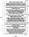
- the navigation method 300 includes illuminating a reticle having a navigation feature, e.g., the reticle 106 (shown in FIG. 1 ) having the navigation feature 110 (shown in FIG. 1 ), as shown with box 310.
- a navigation feature image is generated using the navigation feature, as shown with box 320.
- the navigation feature image is communicated to a projection lens, e.g., the projection lens 108 as shown with box 330.
- the projection lens projects the navigation feature image into a field of view of the projector, as shown with box 340.
- the navigation feature image is displayed on terrain within the field of view of the projector, e.g., the terrain 12 (shown in FIG.
- generating the navigation feature image can include forming a predetermined navigation feature on the reticle using a micro display, e.g., the micro display 212 (shown in FIG. 1 ).
- generating the navigation feature can include forming the navigation feature from image data using the micro display of the reticle.
- a bracket 370 operations for forming the predetermined navigation feature on the reticle using the micro display are shown with a bracket 370 according to an example.
- a grid pattern can be retrieved from a memory and formed on the micro display for display on terrain disposed within the field of view, as shown with box 373.
- indication of water or ice in terrain disposed within the field of view can be received and a water or ice tag formed with the micro display on the reticle in spatial association with the location of the water or ice in the terrain disposed within the field of view, as shown with box 375.
- indication of a mineral in terrain disposed within the field of view can be received and a mineral tag formed with the micro display on the reticle in spatial association with the location of the mineral in terrain disposed within the field of view, as shown with box 377. It is also contemplated that a user input identifying one of more predetermined procedure or schematic can be received, the predetermined procedure or schematic can be retrieved from a memory, and the procedure or schematic formed by the micro display for display on article located on the terrain disposed within the field of view, as shown with boxes 378, 379, and 371.
- FIG. 8 operations for forming the navigation feature from image data using the micro display of the reticle are shown with a bracket 380 according to an example.
- image data of terrain disposed within the field of view e.g., the image data 36 (shown in FIG. 4 )
- An overlay of the terrain disposed within the field of view is formed on the reticle with the micro display, as shown with box 384.
- the image data or the image reconstruction of the micro display can be distorted for displaying the overly conformally on the terrain disposed within the field of view to correct parallax, e.g., between the location of the projector system and a helmet of a space suit or other wearable assembly to which the projector system is fixed, as shown with box 388.
- Navigation systems commonly require external data, such as from GPS and/or Wi-Fi systems.
- the external data generally allows the navigation system to provide an individual with information sufficient to overcome unfamiliarity with the terrain and/or poor situational awareness, the individual thereby being able to safely negotiate the terrain.
- Navigation in environments where such external data is unavailable can be more difficult as the individual negotiating the terrain must typically rely on direct observation of the terrain being negotiated to safely traverse the terrain. This can be difficult under certain types of illumination, such as during lunar trekking where the atmosphere in unable to scatter solar illumination to adequately illuminated terrain not directly illuminated.
- lunar trekking can entail risk of injury and/or equipment damage due to failure to appreciate trip hazards encountered during trekking, such as features in dark shadows and/or bright-lit rises in the lunar terrain.
- projectors are employed to project and display an image in the user field of view.
- the displayed image allows the user to appreciate features presenting trip hazards within the user field of view that are to appreciate, providing situational awareness to the user and thereby limiting the risk of injury and/or equipment damage while negotiating the terrain.
- projectors described herein include a high-bright projector arranged to display images ahead of the user that provide information about the terrain being negotiated by the user.
- the projector projects a grid pattern for display in field of view, the grid pattern overlaying features in the terrain.
- the projector can employ a laser source (or other display illumination device with a slow lens), the displayed grid thereby in-focus within a depth of focus extending the horizon of the user's field of view.
- a projector system includes the projector and a spectral sensor.
- the spectral sensor acquires spectral data from the terrain being negotiation by the user.
- the spectral data contains spectral information regarding composition of the terrain being negotiated by the user, e.g., presence of water or ice and/or minerals of interest.
- the projector system identifies locations of water or ice and/or minerals of interest in terrain, inserts a flag in image projected by the projector, and displays the flag on the terrain in association with location of the water or ice and/or mineral of interest in the terrain being negotiated by the user.
- this allows user to exploit water or ice and/or minerals encountered as the user traverses the terrain as well as to avoid hazards presented by features in the terrain.
- a projector system includes the projector and an imaging system.
- the imaging device acquires image data including depth data of the terrain being negotiated by the user, the image data be reconstructed by create an overlay of the terrain being negotiated by the user, and that the overlay be projected and conformal displayed on the terrain being negotiated by the user.
- conformally displaying an image of the terrain on the terrain ahead of the user allows the user to appreciate rocks, holes, craters and/or other obstacles in terrain traversed by the user.
- the imaging device can include a time-of-flight sensor, a structured light sensor, or a lidar sensor.
- Reconstructing the image can include modifying, e.g., distorting the image for parallax correction, the projected the image to compensate for difference between the sensor location and/or the projector location relative to the location of the user and/or the field of view of the user.
Landscapes
- Engineering & Computer Science (AREA)
- Physics & Mathematics (AREA)
- Radar, Positioning & Navigation (AREA)
- Remote Sensing (AREA)
- General Physics & Mathematics (AREA)
- Multimedia (AREA)
- Signal Processing (AREA)
- Optics & Photonics (AREA)
- Automation & Control Theory (AREA)
- Theoretical Computer Science (AREA)
- Geometry (AREA)
- Projection Apparatus (AREA)
Description
- The present disclosure is generally related to navigation, and more particularly to navigating terrain where ambient illumination is limited or degraded.
- Navigation devices are commonly employed to assist with navigation in environments with limited and/or degraded illumination. For example, navigation devices in terrestrial settings generally have the capability to obtain external data from Wi-Fi systems to provide the user with information to assist in navigation. Some navigation devices can also obtain external data from global positioning satellites (GPS) to provide the user with information to assist in navigation. Access to such sources of external data typically reduce the risk of injury or accident while navigating environments under conditions of limited or degraded illumination.
- In some environments access to Wi-Fi and/or GPS can be limited, such as due to interruption or absence of the infrastructure required for Wi-Fi and/or GPS communication. For example, Wi-Fi and GPS communication is generally unavailable in lunar environments. Lunar trekkers are therefore typically unable employ Wi-Fi and GPS-based utilities and must rely upon solar illumination to appreciate features in lunar terrain being traversed to navigate the lunar environment. Since the lunar atmosphere is too thin to sufficiently scatter ambient solar illumination to illuminate features shielded from direct solar illumination, it can be difficult for lunar trekkers to appreciate certain features, e.g., depths of recesses and features in shaded areas. Failure to appreciate such features can increase the risk of injury and/or equipment damage during lunar trekking due to tripping over rises or stumbling over.
- Such conventional systems and methods have generally been acceptable for their intended purpose. However, there remains a need in the art for improved systems and methods for navigating environments having limited and/or degraded illumination. The present disclosure provides a solution to this need.
DE 11 2018 001394 T5 describes a run support device.US 2018/361912 A1 describes a scanning headlight.DE 10 2015 200748 A1 describes a motor vehicle with a driver assistance system.US 2006/153427 A1 describes image methods for determining contour of terrain. 2018/341811 A1 describes a computing system and augmented reality. - A projector system is defined in
claim 1. - In addition to one or more of the features described above, further examples of the projector may include that the light source includes a laser arranged to illuminate the navigation feature with laser light.
- In addition to one or more of the features described above, further examples of the projector may include that the light source includes a visible source arranged to illuminate the navigation feature with visible light.
- In addition to one or more of the features described above, further examples of the projector may include that the navigation feature is fixed to the reticle and defines a grid pattern.
- In addition to one or more of the features described above, further examples of the projector may include the navigation feature includes an overlay of the terrain disposed within the field of view of the projector.
- In addition to one or more of the features described above, further examples of the projector may include a sensor in communication with the terrain disposed within the field of view of the projector.
- In addition to one or more of the features described above, further examples of the projector may include that the sensor includes a time-of-flight sensor or a structured light sensor optically coupled to the terrain disposed within the field of view of the projector.
- In addition to one or more of the features described above, further examples of the projector may include the projection lens has a slow lens or a laser scanning system.
- In addition to one or more of the features described above, further examples of the projector may include an upper torso hard shell having a helmet seat and a shoulder portion, and a helmet fixed to the helmet seat of the upper torso hard shell, wherein the projector is coupled to the shoulder portion of the upper torso hard shell.
- In addition to one or more of the features described above, further examples of the projector may include that the projector is fixed relative to the helmet.
- In addition to one or more of the features described above, further examples of the projector may include a stabilization module coupled to the projector and arranged to allow the upper torso hard shell to move relative to the projector while the projector is fixed relative to the terrain disposed within the field of view of the projector.
- In addition to one or more of the features described above, further examples of the projector may include a shifting element arranged to bypass the navigation feature with light communicated by the light source.
- A projector system is also provided. The projector system includes a projector as described above and a controller. The reticle includes a micro display arranged on the reticle and arranged along the optical axis. The controller is operably connected to the micro display and responsive to instructions recorded on a non-transitory machine-readable memory to illuminate the navigation feature with light source illumination to generate a navigation feature image, project the navigation feature image into the field of view of the projector with the projection lens, and display the navigation feature image on the terrain disposed within the field of the projection lens.
- In addition to one or more of the features described above, or as an alternative, further examples of the projector system may include the instructions further cause the controller to select a color for the at least one of a grid pattern, a water or ice tag, a mineral tag, and an overlay of terrain disposed along the optical axis with the micro display; illuminate the micro display with light having the selected color; and display the at least one of a grid pattern, a water or ice tag, a mineral tag, and an overlay of the terrain disposed along the optical axis on the terrain disposed along the optical axis with the selected color.
- In addition to one or more of the features described above, or as an alternative, further examples of the projector system may include a time-of-flight sensor or a structured light sensor disposed in communication with the controller and having a field of view intersecting the optical axis of the projector, and that the instructions cause the controller to acquire image data of the terrain disposed along the optical axis; and reconstruct an image of the terrain with the micro display; and project the image of the terrain by illuminating the micro display with the light source for display on the terrain from the which the image data was acquired.
- In addition to one or more of the features described above, or as an alternative, further examples of the projector system may include that reconstructing the image includes distorting the image for conformal display on the terrain disposed along the optical axis.
- In addition to one or more of the features described above, or as an alternative, further examples of the projector system may include that the instructions further cause the controller to generate a one or more of a predetermined map, a predetermined schematic, and a predetermined procedure with the micro display; and project an image of the one or more of a predetermined map, a predetermined schematic, and a predetermined procedure along the optical axis with the light source.
- A navigation method is additionally provided. The method includes, at a projector as described above, illuminating the navigation feature with light source illumination to generate a navigation feature image, projecting the navigation feature image into a field of view of the projector with the projection lens, and displaying the navigation feature image on terrain disposed within the field of the projection lens.
- The present disclosure provides the capability to display grid patterns and/or navigation information on terrain negotiated by vehicles. In certain environments a grid is projected from the navigation system and displayed on the terrain in the path of the vehicle. The displayed grid conforms to the terrain and provide the vehicle driver, pilot or control system with awareness of the terrain contour. In accordance with certain examples the navigation system includes a sensor device. The sensor device acquires information regarding the terrain in the path of the vehicle and the navigation system projecting information regarding the terrain for display on the terrain. It is also contemplated that, in accordance with certain examples, that the navigation system also projects light on the terrain in the path of the vehicle to illuminate the vehicle path along the terrain.
- The following descriptions should not be considered limiting in any way. With reference to the accompanying drawings, like elements are numbered alike:
-
FIG. 1 is a schematic view of a projector constructed in accordance with the present disclosure, showing a light source optically coupled to a projection lens by a reticle with a pattern; -
FIG. 2 is a perspective view of the projector ofFIG. 1 according to an example, showing the projector fixed to the shoulder portion of an upper torso of a space suit or other wearable assembly; -
FIG. 3 is a perspective view of the projector ofFIG. 1 according to an example, showing a pattern image projected by the projector displayed on terrain and making visible features and contour of the terrain; -
FIG. 4 is a schematic view of the projector ofFIG. 1 according to another example, showing a projector with a sensor for acquiring data from terrain within the field of view of the projector such that the projector projects an overlay on the terrain using the acquired data; -
FIG. 5 is a perspective view of the projector ofFIG. 1 , showing the projector projecting an overlay on lunar terrain including tags derived from data acquired from the terrain by a sensor; and -
FIGS. 6-8 are block diagrams of a navigation method in accordance with the present disclosure, showing operations of the method according to illustrative and non-limiting examples of the method. - Reference will now be made to the drawings wherein like reference numerals identify similar structural features or aspects of the subject disclosure. For purposes of explanation and illustration, and not limitation, a partial view of an example of a projector in accordance with the disclosure is shown in
FIG. 1 and is designated generally byreference character 100. Other embodiments of projectors, projector systems, and navigation methods are provided inFIGS. 2-8 , as will be described. The systems and methods described herein can be used for navigating in environments having limited or degraded illumination, such as while trekking across lunar terrain, though the present disclosure is not limited to lunar trekking or to lunar environments in general. - With reference to
FIG. 1 , theprojector 100 is shown. Theprojector 100 generally includes alight source 102 arranged along anoptical axis 104, areticle 106 optically coupled to thelight source 102 along theoptical axis 104, and aprojection lens 108. Theprojection lens 108 is optically coupled to thereticle 106 along theoptical axis 104 and defines thereon anavigation feature 110 arranged for generating anavigation feature image 10 for display on theterrain 12 disposed within a field ofview 14 of theprojector 100. As illustrated inFIG. 1 theprojector 100 also includes a shiftingelement 112, auser interface 114, astabilization module 116, and ahousing 118. - The
housing 118 has an interior 120 and a mountingfeature 122. Thelight source 102, thereticle 106 and theprojection lens 108 are arranged within theinterior 120 of thehousing 118 and are supported along theoptical axis 104. The mountingfeature 122 is arranged on an exterior of thehousing 118 and is arranged for fixation of theprojector 100 to avehicle 16. In certain non-limiting examples, thevehicle 16 is an aircraft. In accordance with certain non-limiting examples, thevehicle 16 is a terrestrial or marine vehicle. It is also contemplated thatprojector 100 can be fixed to a space suit or other wearable assembly 18 (shown inFIG. 2 ). - The
light source 102 is configured to illuminate thereticle 106 withlight source illumination 20. In this respect thelight source 102 is optically coupled to thereticle 106 along theoptical axis 104 to convey thelight source illumination 20 along theoptical axis 104 to thereticle 106. In certain examples thelight source 102 includes a visiblelight source 124 arranged to communicate visible light along theoptical axis 104. In accordance with certain examples thelight source 102 includes alaser light source 126 arranged to communicate laser light along theoptical axis 104. - The
reticle 106 optically couples theprojection lens 108 to thelight source 102 and defines thereon thenavigation feature 110. In certain examples thereticle 106 includes a plate body formed from a transmissive material, e.g., glass, and is arranged to communicate a portion oflight source illumination 20 incident upon thereticle 106 according to theprojection lens 108 according to shape of thenavigation feature 110. In certain examples thenavigation feature 110 includes atransmissive portion 128 and anopaque portion 130 arranged to generate thenavigation feature image 10 from a portion of thelight source illumination 20 transmitted by thetransmissive portion 128 of thenavigation feature 110. Thereticle 106 communicates thenavigation feature image 10 to theprojection lens 108 along theoptical axis 104. - The
projection lens 108 is optically coupled to thelight source 102 by theoptical axis 104 through thereticle 106 and is arranged to project thenavigation feature image 10 from theprojector 100 along theoptical axis 104. In this respect theprojection lens 108 projects thenavigation feature image 10 within the field ofview 14 of theprojector 100 for display of thenavigation feature image 10 on theterrain 12. - In certain examples the
projection lens 108 includes an expansion lens arranged to project thenavigation feature image 10 within the field ofview 14 of size greater than that of thenavigation feature 110. In accordance with certain examples theprojection lens 108 has an aperture size that cooperates with thenavigation feature 110 to provide depth of field sufficient to resolve thenavigation feature image 10 in the direction of the horizon bounding the field ofview 14, e.g., twenty (20) feet, when theprojector 100 is fixed to the user's shoulder. It is contemplated theprojection lens 108 be a slow lens with a large depth of focus, theprojection lens 108 thereby able to maintain good image quality over long distances and over uneven surfaces such as may be found on lunar terrain. It is also contemplated that a laser scanning system can be employed to draw the image within the field ofview 14 as an alternative to theprojection lens 108. - With reference to
FIG. 2 , theprojector 100 is shown fixed to the space suit or otherwearable assembly 18. In the illustrated example the space suit or otherwearable assembly 18 includes theprojector 100, an upper torsohard shell 22 and ahelmet 24. The upper torsohard shell 22 has ahelmet seat 26, ashoulder portion 28, and aprojector mount 30. Thehelmet 24 provides a helmet field of view contained with the field of view 14 (shown inFIG. 1 ) of theprojector 100, is seated on thehelmet seat 26, and is fixed relative to the upper torsohard shell 22. Theprojector 100 is seated on theprojector mount 30, e.g., with the mounting feature 122 (shown inFIG. 1 ). In certain examples theprojector 100 is fixed relative to the upper torsohard shell 22 by theprojector mount 30. In accordance with certain examples the stabilization module 116 (shown inFIG. 1 ) is arranged between the mountingfeature 122 and theprojector mount 30 located on the upper torsohard shell 22 of the space suit or otherwearable assembly 18. - With reference to
FIG. 3 , theprojector 100 is shown projecting thenavigation feature image 10 and displaying thenavigation feature image 10 on theterrain 12 according to an example. During operation the light source 102 (shown inFIG. 1 ) illuminates the reticle 106 (shown inFIG. 1 ) with the light source illumination 20 (shown inFIG. 1 ). Thereticle 106 in turn modulates illumination incident upon thereticle 106 according to the navigation feature 110 (shown inFIG. 1 ) and communicates a portion of thelight source illumination 20 to the projection lens 108 (shown inFIG. 1 ) as thenavigation feature image 10. Theprojection lens 108 projects thenavigation feature image 10 into the field ofview 14 of theprojector 100. Theterrain 12 disposed within the field ofview 14 displays thenavigation feature image 10 thereon conformally, thenavigation feature image 10 thereby showing contour and shape of theterrain 12 irrespective of whether ambient solar illumination illuminates theterrain 12. In certain examples theprojection lens 108 expands thenavigation feature image 10 to at least partially fill (or entirely fill) the field ofview 14 of theprojector 100 for display on the terrain disposed within the field ofview 14 of theprojector 100. - It is contemplated that the
navigation feature image 10 be formed in a way that allows a user, e.g., a user occupying the space suit or otherwearable assembly 18, to appreciate features and/orcontour 17 on theterrain 12 disposed within the field ofview 14 of theprojector 100. In certain examples thenavigation feature image 10 defines agrid pattern 32 having intersecting grid lines on theterrain 12 such that distortion, e.g., departure from a repetitive pattern, in thegrid pattern 32 corresponds to depth and rises in theterrain 12 otherwise difficult (or impossible) to discern using ambient solar illumination. In certain examples thegrid pattern 32 is a fixed grid pattern, e.g., fixed according to the transmissive portion 128 (shown inFIG. 1 ) and the opaque portion 130 (shown inFIG. 1 ) of the reticle 106 (shown inFIG. 1 ). - With continuing reference to
FIG. 1 , when included in theprojector 100, theuser interface 114 is operably connected to thelight source 102 to control the wavelength (or waveband) of thelight source illumination 20. In certain examples theuser interface 114 is arranged to change color of thelight source illumination 20, and thereby the color of thenavigation feature image 10 displayed on theterrain 12 according to auser input 34 received at theuser interface 114. As will be appreciated by those of skill in the art in view of the present disclosure, changing the color forming thenavigation feature image 10 displayed on theterrain 12 allows a user to select the color of thenavigation feature image 10 as appropriate for the specific user negotiating theterrain 12 and/or the properties of ambient solar illumination in the particular lunar environment. - When included, the shifting
element 112 is arranged to route theoptical axis 104 around thenavigation feature 110 and/or thereticle 106. For example, fold mirrors can be employed to route thelight source illumination 20 about thenavigation feature 110 and/or thereticle 106. Alternatively, thereticle 106 can be displaced from theoptical axis 104. As will be appreciated by those of skill in the art in view of the present disclosure, bypassing thenavigation feature 110 and/or thereticle 106 allows theprojector 100 to illuminate theterrain 12 disposed within the field ofview 14 of theprojector 100 with unmodulated illumination, theprojector 100 thereby operating as a flashlight. This eliminates the need to provision the space suit or otherwearable assembly 18 with a general-purpose flashlight in additional to providing the above-described navigational assistance when traversing theterrain 12. - When included, the
stabilization module 116 allows theprojector 100 to move relative to thevehicle 16 or the space suit or other wearable assembly 18 (shown inFIG. 2 ). For example, when thestabilization module 116 is disengaged, theprojector 100 is fixed relative to thevehicle 16 or the space suit or other wearable assembly 18 (shown inFIG. 2 ). When thestabilization module 116 is engaged theprojector 100 is fixed relative to theterrain 12 such that thevehicle 16 or the space suit or otherwearable assembly 18 is movable relative to theprojector 100. This allows theprojector 100 to locked to a feature of interest in theterrain 12, e.g., an article undergoing repair disposed within the terrain, while thevehicle 16 or the space suit or otherwearable assembly 18 moves relative to theterrain 12. It is contemplated that theprojector 100 be engaged and disengaged using a user input, e.g., theuser input 34, received at theuser interface 114. - With reference to
FIGS. 4 and5 , aprojector system 200 is shown. Theprojector system 200 includes theprojector 100, amicro display 202, and a sensor 204. Theprojector system 200 also includes alink 206 and acontroller 208. - The
projector 100 is as described above and additionally includes themicro display 202. The micro display 204 is operably associated with thecontroller 208 and is arranged to form anavigation feature 210 according to a signal received from thecontroller 208 via thelink 206. In this respect it is contemplated that the micro display 204 be arranged to define within thenavigation feature 210 one or more predetermined indicators in association with features on theterrain 12 disposed within the field ofview 14 of theprojector system 200. For example, thenavigation feature 210 can be defined by the micro display 204 with one or more of amineral tag 214 and/or a water orice tag 216 within agrid 218 is spatial association with minerals and/or water or ice on theterrain 12 disposed within the field ofview 14 when the grid is displayed on theterrain 12. As shown inFIG. 5 , thenavigation feature 210 formed by the micro display 204 forms anavigation feature image 212 including amineral tag image 214A and/or a water orice tag image 216A within agrid image 218A displayed in spatial association on theterrain 12 with the associated mineral and water or ice on the terrain. - In certain examples the
navigation feature 210 can be defined by the micro display 204 to impart into thenavigation feature image 212imagery 220 of theterrain 12 disposed within the field ofview 14 for conformal display on theterrain 12. As shown inFIG. 5 , theimagery 220 is in projected by theprojector system 200 on and displayed onterrain 12 in registration with the imagedterrain 12 as animage 220A. As will be appreciated by those of skill in the art in view of the present disclosure, conformal display of imagery of theterrain 12 on theterrain 12 allows the user to appreciate features of theterrain 12 that are otherwise not illuminated by the ambient solar illumination. - In accordance with certain examples the micro display 204 is arranged to form a schematic or
procedure 222 for display on theterrain 12. The schematic orprocedure 222 can correspond to an article 50 (shown inFIG. 5 ) located on theterrain 12, such as a machine requiring service or repair, the schematic orprocedure 222. As shown inFIG. 5 , it is contemplated that theprojection system 200 project a schematic orprocedure image 222A and display the schematic orprocedure image 222A on thearticle 50 within theterrain 12. As will be appreciated by those of skill in the art in view of the present disclosure, displaying the schematic orprocedure image 222A of thearticle 50 requiring service or repair on the article facilitates service or repair of thearticle 50. - The
sensor 214 is arranged for acquiring sensor data 36 containing information relating to theterrain 12 disposed within the field ofview 14. In this respect thesensor 214 is in communication with theterrain 12 and is operably associated with thecontroller 208 to acquire the sensor data 36. Thecontroller 208 is in turn arranged to generate theimagery 220 of theterrain 12 disposed within the field ofview 14 for conformal display on theterrain 12. Theimagery 220 can include navigational information, such as directional indicator. Theimagery 220 can include an image overlay of the actual terrain as perceived by thesensor 214 that theprojector system 200 projects onto the terrain. For example, an image of objects within a pitch-black depression as well as the contour of the depression can be projected into the depression and one the objects and contour of the depression to show the depth, presence of objects (e.g., rocks, etc.), within the depression. - In certain examples the
sensor 214 includes a time-of-flight sensor 224. In accordance with certain examples thesensor 214 can include a structuredlight sensor 226, such as a lidar sensor. Although shown and described herein as integrated within theprojector 100, e.g., arranged within thehousing 118, it is to be understood and appreciated that thesensor 214 can be separate from theprojector 100, such as asensor 214 carried by the user orremote sensor 214. As will also be appreciated by those of skill in the art in view of the present disclosure in view of the present disclosure, theprojector system 200 can include other types of sensors suitable for ascribing depth information to theterrain 12 disposed within the field ofview 14 theprojector system 200 and remain with the scope of the present disclosure. - The
controller 208 includes thememory 228, aprocessor 230, adevice interface 232, and auser interface 234. Thedevice interface 232 is connected to thesensor 214 and the micro display 204 by thelink 216. Theprocessor 230 is disposed in communication with thedevice interface 232 and is operably connected therethrough to thesensor 214 and the micro display 204 and is disposed in communication with theuser interface 234 and thememory 228. Thememory 228 has a plurality ofprogram modules 236 recorded thereon containing instructions that, when read by theprocessor 230, cause theprocessor 230 execute certain operations. Among those operations are operations for a navigation method 300 (shown inFIG. 6 ), as will be described. - With reference to
FIG. 6 , thenavigation method 300 is shown. Themethod 300 includes illuminating a reticle having a navigation feature, e.g., the reticle 106 (shown inFIG. 1 ) having the navigation feature 110 (shown inFIG. 1 ), as shown withbox 310. A navigation feature image is generated using the navigation feature, as shown withbox 320. The navigation feature image is communicated to a projection lens, e.g., theprojection lens 108 as shown withbox 330. The projection lens projects the navigation feature image into a field of view of the projector, as shown withbox 340. The navigation feature image is displayed on terrain within the field of view of the projector, e.g., the terrain 12 (shown inFIG. 1 ), as shown withbox 350. Features and/or contour of the terrain are negotiated using the displayed image, e.g., by a vehicle operator (shown with box 362) or lunar trekker (shown with box 362), negotiating the terrain, as shown withbox 360. As shown withbracket 370, generating the navigation feature image can include forming a predetermined navigation feature on the reticle using a micro display, e.g., the micro display 212 (shown inFIG. 1 ). As shown withbracket 380, generating the navigation feature can include forming the navigation feature from image data using the micro display of the reticle. - With reference to
FIG. 7 , operations for forming the predetermined navigation feature on the reticle using the micro display are shown with abracket 370 according to an example. As shown withbox 372, a grid pattern can be retrieved from a memory and formed on the micro display for display on terrain disposed within the field of view, as shown withbox 373. As shown withbox 374, indication of water or ice in terrain disposed within the field of view can be received and a water or ice tag formed with the micro display on the reticle in spatial association with the location of the water or ice in the terrain disposed within the field of view, as shown withbox 375. As shown withbox 376, indication of a mineral in terrain disposed within the field of view can be received and a mineral tag formed with the micro display on the reticle in spatial association with the location of the mineral in terrain disposed within the field of view, as shown withbox 377. It is also contemplated that a user input identifying one of more predetermined procedure or schematic can be received, the predetermined procedure or schematic can be retrieved from a memory, and the procedure or schematic formed by the micro display for display on article located on the terrain disposed within the field of view, as shown withboxes - With reference to
FIG. 8 , operations for forming the navigation feature from image data using the micro display of the reticle are shown with abracket 380 according to an example. As shown withbox 382, image data of terrain disposed within the field of view, e.g., the image data 36 (shown inFIG. 4 ), is received. An overlay of the terrain disposed within the field of view is formed on the reticle with the micro display, as shown withbox 384. As shown withbox 386, the image data or the image reconstruction of the micro display can be distorted for displaying the overly conformally on the terrain disposed within the field of view to correct parallax, e.g., between the location of the projector system and a helmet of a space suit or other wearable assembly to which the projector system is fixed, as shown withbox 388. - Navigation systems commonly require external data, such as from GPS and/or Wi-Fi systems. The external data generally allows the navigation system to provide an individual with information sufficient to overcome unfamiliarity with the terrain and/or poor situational awareness, the individual thereby being able to safely negotiate the terrain. Navigation in environments where such external data is unavailable can be more difficult as the individual negotiating the terrain must typically rely on direct observation of the terrain being negotiated to safely traverse the terrain. This can be difficult under certain types of illumination, such as during lunar trekking where the atmosphere in unable to scatter solar illumination to adequately illuminated terrain not directly illuminated. As a consequence, lunar trekking can entail risk of injury and/or equipment damage due to failure to appreciate trip hazards encountered during trekking, such as features in dark shadows and/or bright-lit rises in the lunar terrain.
- In examples described herein projectors are employed to project and display an image in the user field of view. The displayed image allows the user to appreciate features presenting trip hazards within the user field of view that are to appreciate, providing situational awareness to the user and thereby limiting the risk of injury and/or equipment damage while negotiating the terrain. In certain examples projectors described herein include a high-bright projector arranged to display images ahead of the user that provide information about the terrain being negotiated by the user. In accordance with certain examples the projector projects a grid pattern for display in field of view, the grid pattern overlaying features in the terrain. In accordance with certain examples the projector can employ a laser source (or other display illumination device with a slow lens), the displayed grid thereby in-focus within a depth of focus extending the horizon of the user's field of view.
- It is contemplated that, in certain examples, a projector system includes the projector and a spectral sensor. In such examples the spectral sensor acquires spectral data from the terrain being negotiation by the user. The spectral data contains spectral information regarding composition of the terrain being negotiated by the user, e.g., presence of water or ice and/or minerals of interest. In certain examples the projector system identifies locations of water or ice and/or minerals of interest in terrain, inserts a flag in image projected by the projector, and displays the flag on the terrain in association with location of the water or ice and/or mineral of interest in the terrain being negotiated by the user. As will be appreciated by those of skill in the art, this allows user to exploit water or ice and/or minerals encountered as the user traverses the terrain as well as to avoid hazards presented by features in the terrain.
- It is also contemplated that, in accordance with certain examples, a projector system includes the projector and an imaging system. In such examples the imaging device acquires image data including depth data of the terrain being negotiated by the user, the image data be reconstructed by create an overlay of the terrain being negotiated by the user, and that the overlay be projected and conformal displayed on the terrain being negotiated by the user. As will be appreciated by those of skill in the art in view of the present disclosure, conformally displaying an image of the terrain on the terrain ahead of the user allows the user to appreciate rocks, holes, craters and/or other obstacles in terrain traversed by the user. In certain examples the imaging device can include a time-of-flight sensor, a structured light sensor, or a lidar sensor. Reconstructing the image can include modifying, e.g., distorting the image for parallax correction, the projected the image to compensate for difference between the sensor location and/or the projector location relative to the location of the user and/or the field of view of the user.
- The term "about" is intended to include the degree of error associated with measurement of the particular quantity based upon the equipment available at the time of filing the application.
- The terminology used herein is for the purpose of describing particular embodiments only and is not intended to be limiting of the present disclosure. As used herein, the singular forms "a", "an" and "the" are intended to include the plural forms as well, unless the context clearly indicates otherwise. It will be further understood that the terms "comprises" and/or "comprising," when used in this specification, specify the presence of stated features, integers, steps, operations, elements, and/or components, but do not preclude the presence or addition of one or more other features, integers, steps, operations, element components, and/or groups thereof.
- While the present disclosure has been described with reference to an exemplary embodiment or embodiments, it will be understood by those skilled in the art that various changes may be made and equivalents may be substituted for elements thereof without departing from the scope of the present disclosure. In addition, many modifications may be made to adapt a particular situation or material to the teachings of the present disclosure without departing from the essential scope thereof. Therefore, it is intended that the present disclosure not be limited to the particular embodiment disclosed as the best mode contemplated for carrying out this present disclosure, but that the present disclosure will include all embodiments falling within the scope of the claims.
Claims (15)
- A projector system, comprising:
a projector (100), comprising:a light source (102) arranged along an optical axis;a reticle (106) optically coupled to the light source along the optical axis; anda projection lens (108) optically coupled to the reticle along the optical axis,wherein the reticle (106) has a navigation feature defined thereon for displaying an image of the navigation feature projected along the optical axis on terrain disposed within a field of view of the projector;wherein the navigation feature includes one or more of a water or ice tag, or a mineral tag;the projector (100) further comprising a micro display (202) arranged on the reticle (106) and configured to form a grid pattern and the one or more of the water or ice tag, or the mineral tag and an overlay of the terrain disposed within the field of view of the projector;wherein the micro display (202) is arranged along the optical axis; andthe projector system further including a controller (208) operably connected to the micro display (202) and responsive to instructions recorded on a non-transitory machine-readable memory to:receive an indication of the navigation feature disposed within the field of view;illuminate the navigation feature with light source illumination to generate a navigation feature image;project the navigation feature image into the field of view of the projector with the projection lens (108); anddisplay the navigation feature image on the terrain disposed within the field of the projection lens (108). - The projector system of claim 1, whereinthe light source includes a laser arranged to illuminate the navigation feature with laser light, orwherein the light source includes a visible source arranged to illuminate the navigation feature with visible light.
- The projector system of claim 1 or 2, wherein the navigation feature is fixed to the reticle and defines a grid pattern.
- The projector system of any preceding claim,
wherein the navigation feature includes an overlay of the terrain disposed within the field of view of the projector. - The projector system of any preceding claim, further comprising
a sensor in communication with the terrain disposed within the field of view of the projector - The projector system of claim 5 wherein the sensor includes a time-of-flight sensor (223) or a structured light sensor (226) optically coupled to the terrain disposed within the field of view of the projector.
- The projector of any preceding claim, wherein the projection lens includes a slow lens or a laser scanning system.
- The projector system of any preceding claim, further comprising:an upper torso hard shell having a helmet seat and a shoulder portion; anda helmet fixed to the helmet seat of the upper torso hard shell, wherein the projector is coupled to the shoulder portion of the upper torso hard shell.
- The projector system of any preceding claim, wherein the projector is fixed relative to the helmet, or further comprising a stabilization module coupled to the projector and arranged to allow the upper torso hard shell to move relative to the projector while the projector is fixed relative to the terrain disposed within the field of view of the projector.
- The projector system of any preceding claim, further comprising a shifting element arranged to bypass the navigation feature with light communicated by the light source.
- The projector system of claim 1, wherein the instructions cause the controller to:select a color for the at least one of a grid pattern, a water or ice tag, a mineral tag, and an overlay of terrain disposed along the optical axis with the micro display;illuminate the micro display with light having the selected color; anddisplay the at least one of a grid pattern, a water or ice tag, a mineral tag, and an overlay of the terrain disposed along the optical axis on the terrain disposed along the optical axis with the selected color.
- The projector system of claim 1 or 11, further comprising a time-of-flight sensor (224) or a structured light sensor (226) disposed in communication with the controller (208) and having a field of view intersecting the optical axis of the projector, wherein the instructions cause the controller to:acquire image data of the terrain disposed along the optical axis; andreconstruct an image of the terrain with the micro display; andproject the image of the terrain by illuminating the micro display with the light source for display on the terrain from the which the image data was acquired.
- The projector system of claim 12 wherein reconstructing the image includes distorting the image for conformal display on the terrain disposed along the optical axis.
- The projector system of any of claims 1, 11 and 12, wherein the instructions further cause the controller to:generate a one or more of a predetermined map, a predetermined schematic, and a predetermined procedure with the micro display; andproject an image of the one or more of a predetermined map, a predetermined schematic, and a predetermined procedure along the optical axis with the light source.
- A navigation method, using: a projector system as described in claim 1 that includes the projector (102) including the light source (102) arranged along an optical axis, the reticle (106) optically coupled to the light source (102) by the optical axis, and the projection lens (108) optically coupled to the reticle by the optical axis and defining thereon the navigation feature (110), illuminating the navigation feature (110) with light source illumination to generate the navigation feature image; projecting the navigation feature image into the field of view of the projector with the projection lens; and displaying the navigation feature image on terrain disposed within the field of the projection lens.
Applications Claiming Priority (1)
| Application Number | Priority Date | Filing Date | Title |
|---|---|---|---|
| US16/784,827 US11029160B1 (en) | 2020-02-07 | 2020-02-07 | Projectors, projector systems, and methods of navigating terrain using projected images |
Publications (2)
| Publication Number | Publication Date |
|---|---|
| EP3862989A1 EP3862989A1 (en) | 2021-08-11 |
| EP3862989B1 true EP3862989B1 (en) | 2024-03-27 |
Family
ID=74556815
Family Applications (1)
| Application Number | Title | Priority Date | Filing Date |
|---|---|---|---|
| EP21155589.1A Active EP3862989B1 (en) | 2020-02-07 | 2021-02-05 | Projectors, projector systems and methods of navigating terrain using projected images |
Country Status (2)
| Country | Link |
|---|---|
| US (1) | US11029160B1 (en) |
| EP (1) | EP3862989B1 (en) |
Families Citing this family (1)
| Publication number | Priority date | Publication date | Assignee | Title |
|---|---|---|---|---|
| EP4177172A1 (en) | 2021-11-03 | 2023-05-10 | Sony Group Corporation | Illumination-based assistance during extravehicular activity |
Family Cites Families (11)
| Publication number | Priority date | Publication date | Assignee | Title |
|---|---|---|---|---|
| US3614237A (en) | 1969-01-21 | 1971-10-19 | Lockheed Aircraft Corp | Method and apparatus for contour measurement |
| US20060153427A1 (en) * | 2005-01-12 | 2006-07-13 | Zanzucchi Peter J | Image methods for determining contour of terrain |
| US7710545B2 (en) * | 2008-02-13 | 2010-05-04 | The Boeing Company | Scanned laser detection and ranging apparatus |
| US8022986B2 (en) * | 2009-05-19 | 2011-09-20 | Cubic Corporation | Method and apparatus for measuring weapon pointing angles |
| WO2013013127A1 (en) | 2011-07-20 | 2013-01-24 | Goszyk Kurt A | Laser obstacle detector |
| WO2014152470A2 (en) | 2013-03-15 | 2014-09-25 | Tk Holdings, Inc. | Path sensing using structured lighting |
| DE102015200748A1 (en) * | 2015-01-20 | 2016-07-21 | Volkswagen Aktiengesellschaft | Motor vehicle with at least one driver assistance system to support a night drive |
| JP6941916B2 (en) * | 2015-12-28 | 2021-09-29 | 凸版印刷株式会社 | Scanning headlights, scanning headlight control methods and programs |
| US20170216633A1 (en) * | 2016-02-02 | 2017-08-03 | Ilc Dover Ip, Inc. | Compression augmented full pressure suit system |
| JP6833575B2 (en) * | 2017-03-15 | 2021-02-24 | 本田技研工業株式会社 | Walking support device, walking support method, and program |
| US10769438B2 (en) * | 2017-05-23 | 2020-09-08 | Samsung Electronics Company, Ltd. | Augmented reality |
-
2020
- 2020-02-07 US US16/784,827 patent/US11029160B1/en active Active
-
2021
- 2021-02-05 EP EP21155589.1A patent/EP3862989B1/en active Active
Also Published As
| Publication number | Publication date |
|---|---|
| US11029160B1 (en) | 2021-06-08 |
| EP3862989A1 (en) | 2021-08-11 |
Similar Documents
| Publication | Publication Date | Title |
|---|---|---|
| US12061336B2 (en) | Head-up display | |
| US10223835B2 (en) | Augmented reality alignment system and method | |
| EP1160541B1 (en) | Integrated vision system | |
| US7973819B2 (en) | Method and apparatus for determining the position of a moving object, by using visible light communication | |
| US11215819B2 (en) | Head-up display | |
| CN105682973B (en) | Information of vehicles optical projection system and projection arrangement | |
| US5815411A (en) | Electro-optic vision system which exploits position and attitude | |
| US8212662B2 (en) | Automotive display system and display method | |
| US9482540B2 (en) | Navigation display method and system | |
| US20200082570A1 (en) | Method, device and computer-readable storage medium with instructions for setting a head-up display in a transportation vehicle | |
| US20140379260A1 (en) | Vehicle Display Device with Vehicle Movement Compensation | |
| US20170054973A1 (en) | Display device and display method | |
| US20210039495A1 (en) | Head-up display device | |
| JP2020016541A (en) | Vehicle display control device, vehicle display control method, and control program | |
| CN114503008B (en) | Vehicle driving assistance method and system | |
| JP7063856B2 (en) | Display control device | |
| US10891791B2 (en) | Detection and visualization of system uncertainty in the representation of augmented image content in heads-up displays | |
| EP3862989B1 (en) | Projectors, projector systems and methods of navigating terrain using projected images | |
| KR101957896B1 (en) | integrated image and situation display system for remote control and method of displaying the same | |
| WO2021020385A1 (en) | Display control device | |
| US20240101138A1 (en) | Display system | |
| JP2020048013A (en) | Image display control apparatus and method | |
| CN119850901B (en) | A synthetic visual correction method and system based on a head-up display | |
| JP7762754B2 (en) | AR image display device and AR image display program | |
| US20250278911A1 (en) | Method and Device for Operating a Display System Comprising Smartglasses in a Vehicle for Latency-Free Contact-Analogous Display of Vehicle-Fixed and World-Fixed Display Objects |
Legal Events
| Date | Code | Title | Description |
|---|---|---|---|
| PUAI | Public reference made under article 153(3) epc to a published international application that has entered the european phase |
Free format text: ORIGINAL CODE: 0009012 |
|
| STAA | Information on the status of an ep patent application or granted ep patent |
Free format text: STATUS: THE APPLICATION HAS BEEN PUBLISHED |
|
| AK | Designated contracting states |
Kind code of ref document: A1 Designated state(s): AL AT BE BG CH CY CZ DE DK EE ES FI FR GB GR HR HU IE IS IT LI LT LU LV MC MK MT NL NO PL PT RO RS SE SI SK SM TR |
|
| STAA | Information on the status of an ep patent application or granted ep patent |
Free format text: STATUS: REQUEST FOR EXAMINATION WAS MADE |
|
| 17P | Request for examination filed |
Effective date: 20220210 |
|
| RBV | Designated contracting states (corrected) |
Designated state(s): AL AT BE BG CH CY CZ DE DK EE ES FI FR GB GR HR HU IE IS IT LI LT LU LV MC MK MT NL NO PL PT RO RS SE SI SK SM TR |
|
| REG | Reference to a national code |
Ref country code: DE Ref legal event code: R079 Free format text: PREVIOUS MAIN CLASS: G08G0001005000 Ipc: G02B0027010000 Ref country code: DE Ref legal event code: R079 Ref document number: 602021010787 Country of ref document: DE Free format text: PREVIOUS MAIN CLASS: G08G0001005000 Ipc: G02B0027010000 |
|
| GRAP | Despatch of communication of intention to grant a patent |
Free format text: ORIGINAL CODE: EPIDOSNIGR1 |
|
| STAA | Information on the status of an ep patent application or granted ep patent |
Free format text: STATUS: GRANT OF PATENT IS INTENDED |
|
| RIC1 | Information provided on ipc code assigned before grant |
Ipc: G02B 27/01 20060101AFI20230905BHEP |
|
| INTG | Intention to grant announced |
Effective date: 20230929 |
|
| GRAS | Grant fee paid |
Free format text: ORIGINAL CODE: EPIDOSNIGR3 |
|
| GRAA | (expected) grant |
Free format text: ORIGINAL CODE: 0009210 |
|
| STAA | Information on the status of an ep patent application or granted ep patent |
Free format text: STATUS: THE PATENT HAS BEEN GRANTED |
|
| AK | Designated contracting states |
Kind code of ref document: B1 Designated state(s): AL AT BE BG CH CY CZ DE DK EE ES FI FR GB GR HR HU IE IS IT LI LT LU LV MC MK MT NL NO PL PT RO RS SE SI SK SM TR |
|
| REG | Reference to a national code |
Ref country code: GB Ref legal event code: FG4D |
|
| REG | Reference to a national code |
Ref country code: CH Ref legal event code: EP |
|
| REG | Reference to a national code |
Ref country code: DE Ref legal event code: R096 Ref document number: 602021010787 Country of ref document: DE |
|
| REG | Reference to a national code |
Ref country code: IE Ref legal event code: FG4D |
|
| PG25 | Lapsed in a contracting state [announced via postgrant information from national office to epo] |
Ref country code: LT Free format text: LAPSE BECAUSE OF FAILURE TO SUBMIT A TRANSLATION OF THE DESCRIPTION OR TO PAY THE FEE WITHIN THE PRESCRIBED TIME-LIMIT Effective date: 20240327 |
|
| REG | Reference to a national code |
Ref country code: LT Ref legal event code: MG9D |
|
| PG25 | Lapsed in a contracting state [announced via postgrant information from national office to epo] |
Ref country code: GR Free format text: LAPSE BECAUSE OF FAILURE TO SUBMIT A TRANSLATION OF THE DESCRIPTION OR TO PAY THE FEE WITHIN THE PRESCRIBED TIME-LIMIT Effective date: 20240628 |
|
| PG25 | Lapsed in a contracting state [announced via postgrant information from national office to epo] |
Ref country code: HR Free format text: LAPSE BECAUSE OF FAILURE TO SUBMIT A TRANSLATION OF THE DESCRIPTION OR TO PAY THE FEE WITHIN THE PRESCRIBED TIME-LIMIT Effective date: 20240327 Ref country code: RS Free format text: LAPSE BECAUSE OF FAILURE TO SUBMIT A TRANSLATION OF THE DESCRIPTION OR TO PAY THE FEE WITHIN THE PRESCRIBED TIME-LIMIT Effective date: 20240627 |
|
| PG25 | Lapsed in a contracting state [announced via postgrant information from national office to epo] |
Ref country code: RS Free format text: LAPSE BECAUSE OF FAILURE TO SUBMIT A TRANSLATION OF THE DESCRIPTION OR TO PAY THE FEE WITHIN THE PRESCRIBED TIME-LIMIT Effective date: 20240627 Ref country code: NO Free format text: LAPSE BECAUSE OF FAILURE TO SUBMIT A TRANSLATION OF THE DESCRIPTION OR TO PAY THE FEE WITHIN THE PRESCRIBED TIME-LIMIT Effective date: 20240627 Ref country code: LT Free format text: LAPSE BECAUSE OF FAILURE TO SUBMIT A TRANSLATION OF THE DESCRIPTION OR TO PAY THE FEE WITHIN THE PRESCRIBED TIME-LIMIT Effective date: 20240327 Ref country code: HR Free format text: LAPSE BECAUSE OF FAILURE TO SUBMIT A TRANSLATION OF THE DESCRIPTION OR TO PAY THE FEE WITHIN THE PRESCRIBED TIME-LIMIT Effective date: 20240327 Ref country code: GR Free format text: LAPSE BECAUSE OF FAILURE TO SUBMIT A TRANSLATION OF THE DESCRIPTION OR TO PAY THE FEE WITHIN THE PRESCRIBED TIME-LIMIT Effective date: 20240628 Ref country code: FI Free format text: LAPSE BECAUSE OF FAILURE TO SUBMIT A TRANSLATION OF THE DESCRIPTION OR TO PAY THE FEE WITHIN THE PRESCRIBED TIME-LIMIT Effective date: 20240327 Ref country code: BG Free format text: LAPSE BECAUSE OF FAILURE TO SUBMIT A TRANSLATION OF THE DESCRIPTION OR TO PAY THE FEE WITHIN THE PRESCRIBED TIME-LIMIT Effective date: 20240327 |
|
| REG | Reference to a national code |
Ref country code: NL Ref legal event code: MP Effective date: 20240327 |
|
| PG25 | Lapsed in a contracting state [announced via postgrant information from national office to epo] |
Ref country code: SE Free format text: LAPSE BECAUSE OF FAILURE TO SUBMIT A TRANSLATION OF THE DESCRIPTION OR TO PAY THE FEE WITHIN THE PRESCRIBED TIME-LIMIT Effective date: 20240327 Ref country code: LV Free format text: LAPSE BECAUSE OF FAILURE TO SUBMIT A TRANSLATION OF THE DESCRIPTION OR TO PAY THE FEE WITHIN THE PRESCRIBED TIME-LIMIT Effective date: 20240327 |
|
| PG25 | Lapsed in a contracting state [announced via postgrant information from national office to epo] |
Ref country code: NL Free format text: LAPSE BECAUSE OF FAILURE TO SUBMIT A TRANSLATION OF THE DESCRIPTION OR TO PAY THE FEE WITHIN THE PRESCRIBED TIME-LIMIT Effective date: 20240327 |
|
| REG | Reference to a national code |
Ref country code: AT Ref legal event code: MK05 Ref document number: 1670470 Country of ref document: AT Kind code of ref document: T Effective date: 20240327 |
|
| PG25 | Lapsed in a contracting state [announced via postgrant information from national office to epo] |
Ref country code: NL Free format text: LAPSE BECAUSE OF FAILURE TO SUBMIT A TRANSLATION OF THE DESCRIPTION OR TO PAY THE FEE WITHIN THE PRESCRIBED TIME-LIMIT Effective date: 20240327 |
|
| PG25 | Lapsed in a contracting state [announced via postgrant information from national office to epo] |
Ref country code: IS Free format text: LAPSE BECAUSE OF FAILURE TO SUBMIT A TRANSLATION OF THE DESCRIPTION OR TO PAY THE FEE WITHIN THE PRESCRIBED TIME-LIMIT Effective date: 20240727 |
|
| PG25 | Lapsed in a contracting state [announced via postgrant information from national office to epo] |
Ref country code: PT Free format text: LAPSE BECAUSE OF FAILURE TO SUBMIT A TRANSLATION OF THE DESCRIPTION OR TO PAY THE FEE WITHIN THE PRESCRIBED TIME-LIMIT Effective date: 20240729 Ref country code: SM Free format text: LAPSE BECAUSE OF FAILURE TO SUBMIT A TRANSLATION OF THE DESCRIPTION OR TO PAY THE FEE WITHIN THE PRESCRIBED TIME-LIMIT Effective date: 20240327 |
|
| PG25 | Lapsed in a contracting state [announced via postgrant information from national office to epo] |
Ref country code: ES Free format text: LAPSE BECAUSE OF FAILURE TO SUBMIT A TRANSLATION OF THE DESCRIPTION OR TO PAY THE FEE WITHIN THE PRESCRIBED TIME-LIMIT Effective date: 20240327 |
|
| PG25 | Lapsed in a contracting state [announced via postgrant information from national office to epo] |
Ref country code: CZ Free format text: LAPSE BECAUSE OF FAILURE TO SUBMIT A TRANSLATION OF THE DESCRIPTION OR TO PAY THE FEE WITHIN THE PRESCRIBED TIME-LIMIT Effective date: 20240327 Ref country code: EE Free format text: LAPSE BECAUSE OF FAILURE TO SUBMIT A TRANSLATION OF THE DESCRIPTION OR TO PAY THE FEE WITHIN THE PRESCRIBED TIME-LIMIT Effective date: 20240327 |
|
| PG25 | Lapsed in a contracting state [announced via postgrant information from national office to epo] |
Ref country code: AT Free format text: LAPSE BECAUSE OF FAILURE TO SUBMIT A TRANSLATION OF THE DESCRIPTION OR TO PAY THE FEE WITHIN THE PRESCRIBED TIME-LIMIT Effective date: 20240327 |
|
| PG25 | Lapsed in a contracting state [announced via postgrant information from national office to epo] |
Ref country code: PL Free format text: LAPSE BECAUSE OF FAILURE TO SUBMIT A TRANSLATION OF THE DESCRIPTION OR TO PAY THE FEE WITHIN THE PRESCRIBED TIME-LIMIT Effective date: 20240327 |
|
| PG25 | Lapsed in a contracting state [announced via postgrant information from national office to epo] |
Ref country code: SK Free format text: LAPSE BECAUSE OF FAILURE TO SUBMIT A TRANSLATION OF THE DESCRIPTION OR TO PAY THE FEE WITHIN THE PRESCRIBED TIME-LIMIT Effective date: 20240327 |
|
| PG25 | Lapsed in a contracting state [announced via postgrant information from national office to epo] |
Ref country code: SM Free format text: LAPSE BECAUSE OF FAILURE TO SUBMIT A TRANSLATION OF THE DESCRIPTION OR TO PAY THE FEE WITHIN THE PRESCRIBED TIME-LIMIT Effective date: 20240327 Ref country code: SK Free format text: LAPSE BECAUSE OF FAILURE TO SUBMIT A TRANSLATION OF THE DESCRIPTION OR TO PAY THE FEE WITHIN THE PRESCRIBED TIME-LIMIT Effective date: 20240327 Ref country code: RO Free format text: LAPSE BECAUSE OF FAILURE TO SUBMIT A TRANSLATION OF THE DESCRIPTION OR TO PAY THE FEE WITHIN THE PRESCRIBED TIME-LIMIT Effective date: 20240327 Ref country code: PT Free format text: LAPSE BECAUSE OF FAILURE TO SUBMIT A TRANSLATION OF THE DESCRIPTION OR TO PAY THE FEE WITHIN THE PRESCRIBED TIME-LIMIT Effective date: 20240729 Ref country code: PL Free format text: LAPSE BECAUSE OF FAILURE TO SUBMIT A TRANSLATION OF THE DESCRIPTION OR TO PAY THE FEE WITHIN THE PRESCRIBED TIME-LIMIT Effective date: 20240327 Ref country code: IS Free format text: LAPSE BECAUSE OF FAILURE TO SUBMIT A TRANSLATION OF THE DESCRIPTION OR TO PAY THE FEE WITHIN THE PRESCRIBED TIME-LIMIT Effective date: 20240727 Ref country code: ES Free format text: LAPSE BECAUSE OF FAILURE TO SUBMIT A TRANSLATION OF THE DESCRIPTION OR TO PAY THE FEE WITHIN THE PRESCRIBED TIME-LIMIT Effective date: 20240327 Ref country code: EE Free format text: LAPSE BECAUSE OF FAILURE TO SUBMIT A TRANSLATION OF THE DESCRIPTION OR TO PAY THE FEE WITHIN THE PRESCRIBED TIME-LIMIT Effective date: 20240327 Ref country code: CZ Free format text: LAPSE BECAUSE OF FAILURE TO SUBMIT A TRANSLATION OF THE DESCRIPTION OR TO PAY THE FEE WITHIN THE PRESCRIBED TIME-LIMIT Effective date: 20240327 Ref country code: AT Free format text: LAPSE BECAUSE OF FAILURE TO SUBMIT A TRANSLATION OF THE DESCRIPTION OR TO PAY THE FEE WITHIN THE PRESCRIBED TIME-LIMIT Effective date: 20240327 |
|
| PG25 | Lapsed in a contracting state [announced via postgrant information from national office to epo] |
Ref country code: IT Free format text: LAPSE BECAUSE OF FAILURE TO SUBMIT A TRANSLATION OF THE DESCRIPTION OR TO PAY THE FEE WITHIN THE PRESCRIBED TIME-LIMIT Effective date: 20240327 |
|
| PG25 | Lapsed in a contracting state [announced via postgrant information from national office to epo] |
Ref country code: IT Free format text: LAPSE BECAUSE OF FAILURE TO SUBMIT A TRANSLATION OF THE DESCRIPTION OR TO PAY THE FEE WITHIN THE PRESCRIBED TIME-LIMIT Effective date: 20240327 |
|
| REG | Reference to a national code |
Ref country code: DE Ref legal event code: R097 Ref document number: 602021010787 Country of ref document: DE |
|
| PG25 | Lapsed in a contracting state [announced via postgrant information from national office to epo] |
Ref country code: DK Free format text: LAPSE BECAUSE OF FAILURE TO SUBMIT A TRANSLATION OF THE DESCRIPTION OR TO PAY THE FEE WITHIN THE PRESCRIBED TIME-LIMIT Effective date: 20240327 |
|
| PG25 | Lapsed in a contracting state [announced via postgrant information from national office to epo] |
Ref country code: DK Free format text: LAPSE BECAUSE OF FAILURE TO SUBMIT A TRANSLATION OF THE DESCRIPTION OR TO PAY THE FEE WITHIN THE PRESCRIBED TIME-LIMIT Effective date: 20240327 |
|
| PLBE | No opposition filed within time limit |
Free format text: ORIGINAL CODE: 0009261 |
|
| STAA | Information on the status of an ep patent application or granted ep patent |
Free format text: STATUS: NO OPPOSITION FILED WITHIN TIME LIMIT |
|
| 26N | No opposition filed |
Effective date: 20250103 |
|
| PG25 | Lapsed in a contracting state [announced via postgrant information from national office to epo] |
Ref country code: SI Free format text: LAPSE BECAUSE OF FAILURE TO SUBMIT A TRANSLATION OF THE DESCRIPTION OR TO PAY THE FEE WITHIN THE PRESCRIBED TIME-LIMIT Effective date: 20240327 |
|
| PG25 | Lapsed in a contracting state [announced via postgrant information from national office to epo] |
Ref country code: MC Free format text: LAPSE BECAUSE OF FAILURE TO SUBMIT A TRANSLATION OF THE DESCRIPTION OR TO PAY THE FEE WITHIN THE PRESCRIBED TIME-LIMIT Effective date: 20240327 |
|
| REG | Reference to a national code |
Ref country code: CH Ref legal event code: PL |
|
| PG25 | Lapsed in a contracting state [announced via postgrant information from national office to epo] |
Ref country code: LU Free format text: LAPSE BECAUSE OF NON-PAYMENT OF DUE FEES Effective date: 20250205 |
|
| PG25 | Lapsed in a contracting state [announced via postgrant information from national office to epo] |
Ref country code: CH Free format text: LAPSE BECAUSE OF NON-PAYMENT OF DUE FEES Effective date: 20250228 |
|
| REG | Reference to a national code |
Ref country code: BE Ref legal event code: MM Effective date: 20250228 |
|
| PG25 | Lapsed in a contracting state [announced via postgrant information from national office to epo] |
Ref country code: BE Free format text: LAPSE BECAUSE OF NON-PAYMENT OF DUE FEES Effective date: 20250228 |
|
| PG25 | Lapsed in a contracting state [announced via postgrant information from national office to epo] |
Ref country code: IE Free format text: LAPSE BECAUSE OF NON-PAYMENT OF DUE FEES Effective date: 20250205 |
|
| PGFP | Annual fee paid to national office [announced via postgrant information from national office to epo] |
Ref country code: GB Payment date: 20260121 Year of fee payment: 6 |
|
| PGFP | Annual fee paid to national office [announced via postgrant information from national office to epo] |
Ref country code: DE Payment date: 20260121 Year of fee payment: 6 |
|
| PGFP | Annual fee paid to national office [announced via postgrant information from national office to epo] |
Ref country code: FR Payment date: 20260121 Year of fee payment: 6 |