EP3862943A1 - Monitoring control apparatus, monitoring control method, monitoring system, and medium - Google Patents
Monitoring control apparatus, monitoring control method, monitoring system, and medium Download PDFInfo
- Publication number
- EP3862943A1 EP3862943A1 EP21155977.8A EP21155977A EP3862943A1 EP 3862943 A1 EP3862943 A1 EP 3862943A1 EP 21155977 A EP21155977 A EP 21155977A EP 3862943 A1 EP3862943 A1 EP 3862943A1
- Authority
- EP
- European Patent Office
- Prior art keywords
- capturing
- target device
- job
- unit
- target
- Prior art date
- Legal status (The legal status is an assumption and is not a legal conclusion. Google has not performed a legal analysis and makes no representation as to the accuracy of the status listed.)
- Granted
Links
Images







Classifications
-
- G—PHYSICS
- G06—COMPUTING OR CALCULATING; COUNTING
- G06F—ELECTRIC DIGITAL DATA PROCESSING
- G06F3/00—Input arrangements for transferring data to be processed into a form capable of being handled by the computer; Output arrangements for transferring data from processing unit to output unit, e.g. interface arrangements
- G06F3/12—Digital output to print unit, e.g. line printer, chain printer
- G06F3/1201—Dedicated interfaces to print systems
- G06F3/1223—Dedicated interfaces to print systems specifically adapted to use a particular technique
- G06F3/1275—Print workflow management, e.g. defining or changing a workflow, cross publishing
-
- G—PHYSICS
- G06—COMPUTING OR CALCULATING; COUNTING
- G06F—ELECTRIC DIGITAL DATA PROCESSING
- G06F3/00—Input arrangements for transferring data to be processed into a form capable of being handled by the computer; Output arrangements for transferring data from processing unit to output unit, e.g. interface arrangements
- G06F3/12—Digital output to print unit, e.g. line printer, chain printer
- G06F3/1201—Dedicated interfaces to print systems
- G06F3/1202—Dedicated interfaces to print systems specifically adapted to achieve a particular effect
- G06F3/1203—Improving or facilitating administration, e.g. print management
-
- G—PHYSICS
- G06—COMPUTING OR CALCULATING; COUNTING
- G06Q—INFORMATION AND COMMUNICATION TECHNOLOGY [ICT] SPECIALLY ADAPTED FOR ADMINISTRATIVE, COMMERCIAL, FINANCIAL, MANAGERIAL OR SUPERVISORY PURPOSES; SYSTEMS OR METHODS SPECIALLY ADAPTED FOR ADMINISTRATIVE, COMMERCIAL, FINANCIAL, MANAGERIAL OR SUPERVISORY PURPOSES, NOT OTHERWISE PROVIDED FOR
- G06Q10/00—Administration; Management
- G06Q10/06—Resources, workflows, human or project management; Enterprise or organisation planning; Enterprise or organisation modelling
- G06Q10/063—Operations research, analysis or management
- G06Q10/0631—Resource planning, allocation, distributing or scheduling for enterprises or organisations
-
- G—PHYSICS
- G06—COMPUTING OR CALCULATING; COUNTING
- G06Q—INFORMATION AND COMMUNICATION TECHNOLOGY [ICT] SPECIALLY ADAPTED FOR ADMINISTRATIVE, COMMERCIAL, FINANCIAL, MANAGERIAL OR SUPERVISORY PURPOSES; SYSTEMS OR METHODS SPECIALLY ADAPTED FOR ADMINISTRATIVE, COMMERCIAL, FINANCIAL, MANAGERIAL OR SUPERVISORY PURPOSES, NOT OTHERWISE PROVIDED FOR
- G06Q50/00—Information and communication technology [ICT] specially adapted for implementation of business processes of specific business sectors, e.g. utilities or tourism
- G06Q50/10—Services
-
- G—PHYSICS
- G06—COMPUTING OR CALCULATING; COUNTING
- G06F—ELECTRIC DIGITAL DATA PROCESSING
- G06F3/00—Input arrangements for transferring data to be processed into a form capable of being handled by the computer; Output arrangements for transferring data from processing unit to output unit, e.g. interface arrangements
- G06F3/12—Digital output to print unit, e.g. line printer, chain printer
- G06F3/1201—Dedicated interfaces to print systems
- G06F3/1223—Dedicated interfaces to print systems specifically adapted to use a particular technique
- G06F3/1237—Print job management
-
- G—PHYSICS
- G06—COMPUTING OR CALCULATING; COUNTING
- G06F—ELECTRIC DIGITAL DATA PROCESSING
- G06F3/00—Input arrangements for transferring data to be processed into a form capable of being handled by the computer; Output arrangements for transferring data from processing unit to output unit, e.g. interface arrangements
- G06F3/12—Digital output to print unit, e.g. line printer, chain printer
- G06F3/1201—Dedicated interfaces to print systems
- G06F3/1223—Dedicated interfaces to print systems specifically adapted to use a particular technique
- G06F3/1237—Print job management
- G06F3/1267—Job repository, e.g. non-scheduled jobs, delay printing
-
- G—PHYSICS
- G06—COMPUTING OR CALCULATING; COUNTING
- G06Q—INFORMATION AND COMMUNICATION TECHNOLOGY [ICT] SPECIALLY ADAPTED FOR ADMINISTRATIVE, COMMERCIAL, FINANCIAL, MANAGERIAL OR SUPERVISORY PURPOSES; SYSTEMS OR METHODS SPECIALLY ADAPTED FOR ADMINISTRATIVE, COMMERCIAL, FINANCIAL, MANAGERIAL OR SUPERVISORY PURPOSES, NOT OTHERWISE PROVIDED FOR
- G06Q10/00—Administration; Management
- G06Q10/06—Resources, workflows, human or project management; Enterprise or organisation planning; Enterprise or organisation modelling
- G06Q10/063—Operations research, analysis or management
- G06Q10/0631—Resource planning, allocation, distributing or scheduling for enterprises or organisations
- G06Q10/06311—Scheduling, planning or task assignment for a person or group
- G06Q10/063114—Status monitoring or status determination for a person or group
-
- G—PHYSICS
- G06—COMPUTING OR CALCULATING; COUNTING
- G06Q—INFORMATION AND COMMUNICATION TECHNOLOGY [ICT] SPECIALLY ADAPTED FOR ADMINISTRATIVE, COMMERCIAL, FINANCIAL, MANAGERIAL OR SUPERVISORY PURPOSES; SYSTEMS OR METHODS SPECIALLY ADAPTED FOR ADMINISTRATIVE, COMMERCIAL, FINANCIAL, MANAGERIAL OR SUPERVISORY PURPOSES, NOT OTHERWISE PROVIDED FOR
- G06Q10/00—Administration; Management
- G06Q10/10—Office automation; Time management
- G06Q10/103—Workflow collaboration or project management
-
- G—PHYSICS
- G06—COMPUTING OR CALCULATING; COUNTING
- G06V—IMAGE OR VIDEO RECOGNITION OR UNDERSTANDING
- G06V20/00—Scenes; Scene-specific elements
- G06V20/40—Scenes; Scene-specific elements in video content
-
- G—PHYSICS
- G06—COMPUTING OR CALCULATING; COUNTING
- G06V—IMAGE OR VIDEO RECOGNITION OR UNDERSTANDING
- G06V20/00—Scenes; Scene-specific elements
- G06V20/40—Scenes; Scene-specific elements in video content
- G06V20/41—Higher-level, semantic clustering, classification or understanding of video scenes, e.g. detection, labelling or Markovian modelling of sport events or news items
-
- G—PHYSICS
- G06—COMPUTING OR CALCULATING; COUNTING
- G06V—IMAGE OR VIDEO RECOGNITION OR UNDERSTANDING
- G06V20/00—Scenes; Scene-specific elements
- G06V20/50—Context or environment of the image
- G06V20/52—Surveillance or monitoring of activities, e.g. for recognising suspicious objects
-
- H—ELECTRICITY
- H04—ELECTRIC COMMUNICATION TECHNIQUE
- H04N—PICTORIAL COMMUNICATION, e.g. TELEVISION
- H04N23/00—Cameras or camera modules comprising electronic image sensors; Control thereof
- H04N23/60—Control of cameras or camera modules
- H04N23/62—Control of parameters via user interfaces
-
- H—ELECTRICITY
- H04—ELECTRIC COMMUNICATION TECHNIQUE
- H04N—PICTORIAL COMMUNICATION, e.g. TELEVISION
- H04N7/00—Television systems
- H04N7/18—Closed-circuit television [CCTV] systems, i.e. systems in which the video signal is not broadcast
- H04N7/181—Closed-circuit television [CCTV] systems, i.e. systems in which the video signal is not broadcast for receiving images from a plurality of remote sources
-
- G—PHYSICS
- G06—COMPUTING OR CALCULATING; COUNTING
- G06V—IMAGE OR VIDEO RECOGNITION OR UNDERSTANDING
- G06V20/00—Scenes; Scene-specific elements
- G06V20/40—Scenes; Scene-specific elements in video content
- G06V20/44—Event detection
Definitions
- the present invention relates to a monitoring control apparatus, a monitoring control method, a monitoring system, and a medium which are associated with the collection of printing factory operation statuses by, for example, a network camera.
- a printer used in a printing factory can collect information about the operation state of a device and notify the collected information to a workflow system as a management system via a network.
- operation states associated with preprocessing operations and postprocessing operations associated with device operations cannot be automatically collected via the printer.
- preprocessing operations include confirmation of operation instructions and data, preparation of a device and paper, and test printing.
- postprocessing operations include product inspection and checkup with instructions.
- a camera connected to a network captures indications on the control panels of a printer and a postprocessor, the lighting state of a pilot lamp, and the state of a worker around a device, detects changes in operation state, and collects corresponding information as events.
- the present invention more quickly detects a change in operation state by switching capturing targets in accordance with the statuses of devices to be observed.
- the present invention in its first aspect provides a monitoring control apparatus as specified in claims 1 to 7.
- the present invention in its second aspect provides a monitoring system as specified in claim 8.
- the present invention in its third aspect provides a computer readable medium as specified in claim 9.
- the present invention in its fourth aspect provides a monitoring control method as specified in claim 10.
- a change in operation state can be more quickly detected by switching capturing targets in accordance the statues of devices to be observed.
- Fig. 1 is a block diagram showing the configuration of an event collection system according to this embodiment.
- the event collection system includes a workflow system 101, a camera management system 102, a network camera 103, a printer 104, a postprocessor 105, and a DB 106 which are configured to be communicable with each other via a network 100.
- the printer 104 is network-connected to the workflow system 101.
- the embodiment will exemplify a case in which there are a plurality of postprocessors 105 that perform postprocessing (edge trimming, bookbinding, and the like) after printing, and the respective postprocessors are network-connected.
- this system may include a plurality of printers 104 and may not include a plurality of postprocessors 105.
- the network is, for example, a so-called communication network implemented by a LAN such as the Internet, WAN, telephone line, or the like, and may be at least capable of transmitting and receiving data.
- the event collection system can be regarded as a monitoring system that monitors devices to be observed.
- the workflow system 101 is a system that manages printing by the printer 104 and postprocessing by the postprocessor 105, and manages job information including print data, print settings, device settings of postprocessors, and process information which are used for order production. In addition, the workflow system 101 receives and manages device operation states and process start and end instructions from the printer 104 and the postprocessor 105.
- the workflow system 101 may be implemented by programs executed by an information processing apparatus.
- the workflow system 101 generates a print job and a postprocessing job to be transmitted to devices connected via the network based on information such as document data as source data, a format (print settings), and postprocessing settings, and transmits the jobs to the respective devices.
- the workflow system 101 generates instructions for instructing a processing procedure and presents the instructions as a printed product data to the operator.
- the operator makes preparations for printing and postprocessing by each device, that is, preprocessing operations, in accordance with the instructions and causes each device to execute a target process.
- the preprocessing operations include, for example, moving an output from a front-stage device in accordance with instructions and placing the output at a predetermined position on a next-stage device.
- a series of processes up to finishing one document into a printed product is called a job, and the unit of processing included in the job is called a process.
- operation instruction information generated by a workflow system concerning the process or processing based on the operation instruction information is sometimes called a "job".
- jobs include a print job and a processing job by a postprocessor.
- the camera management system 102 manages a plurality of network cameras 103.
- the camera management system 102 instructs the network cameras 103 to perform capturing and receives the captured videos.
- the camera management system 102 detects the presence/absence of preprocessing operations for the respective devices, including the printer 104 and the postprocessor 105, from the received videos, and transmits the corresponding information as events to the DB 106.
- the camera management system 102 may be implemented by the programs executed by an information processing apparatus.
- the camera management system controls the monitoring function implemented by the monitoring control system, and hence can also be called a monitoring control apparatus.
- a monitoring control method is executed by the processing executed by the monitoring control apparatus.
- the network camera 103 is a camera capable of zooming which is mounted on a camera platform whose capturing direction can be controlled by pan and tilt operations in accordance with instructions from the camera management system. In addition, the network camera 103 starts capturing, transmits a captured image, and finishes capturing in accordance with instructions from the camera management system.
- the printer 104 receives print data and print settings from the workflow system 101 and performs printing. Accompanying such operations, the printer 104 transmits, to the workflow system 101, its own device states (such as in progress, normal termination, error termination, and waiting state) together with information that can specify a job and a process.
- the postprocessor 105 receives the device settings of a postprocessing device from the workflow system 101 and performs postprocessing. Accompanying such operations, the postprocessor 105 transmits, to the workflow system 101, its own device states (such as in progress, normal termination, error termination, and standby state) together with information that can specify a job and a process.
- the DB 106 receives and holds events from the camera management system 102. The DB 106 also generates an image that allows checking of the operation state of a printing factory from job information and events from the workflow system 101 in accordance with a request from a client PC (not shown).
- Fig. 2A is a block diagram showing the hardware configurations of the workflow system 101, the camera management system 102, and the DB 106 in Fig. 1 .
- a user interface 201 allows the user to input and output information using a display, keyboard, mouse, touch panel, and the like.
- a network interface 203 is connected to the network 100 such as a LAN to communicate with other computers and network devices. Incorporated programs and data are recorded in a ROM 204.
- a RAM 205 is a temporary storage area.
- a secondary storage device 206 is a secondary storage typified by an HDD.
- a CPU 202 executes programs read out from the ROM 204, the RAM 205, the secondary storage device 206, and the like. Each unit is connected via a bus 207.
- Fig. 2B is a block diagram showing the hardware configuration of the network camera 103 in Fig. 1 .
- a user interface 211 allows connection and operation from another computer via the remote shell.
- a network interface 213 connects to a network such as a LAN to communicate with another computer or network device. Incorporated programs and data are recorded in a ROM 214.
- a RAM 215 is a temporary memory area.
- a secondary storage device 216 is a secondary storage typified by an HDD.
- a CPU 212 executes programs read out from the ROM 214, the RAM 215, the secondary storage device 216, and the like.
- An image capturing unit 217 includes a CCD and stores the videos obtained by capturing images of imaging targets in the secondary storage device 216. Each unit is connected via a bus 218.
- Fig. 2C is a block diagram showing the hardware configuration of the printer 104 in Fig. 1 .
- a user interface 221 allows the user to input and output information by using a display, keyboard, touch panel, and the like.
- a network interface 223 is connected to the network 100 such as a LAN to communicate with other computers and network devices. Incorporated programs and data are recorded in a ROM 224.
- a RAM 225 is a temporary storage area.
- a secondary storage device 226 is a secondary storage typified by an HDD.
- a CPU 222 executes programs read out from the ROM 224, the RAM 225, the secondary storage device 226, and the like.
- a print engine 227 prints data on paper (sheet). Each unit is connected via a bus 228.
- the postprocessor 105 may have a configuration obtained by replacing the print engine 227 of the configuration in Fig. 2C with a device for postprocessing.
- Figs. 3A to 3F show the software configurations of the workflow system 101, the camera management system 102, the network camera 103, the printer 104, the postprocessor 105, and the DB 106 shown in Fig. 1 .
- the operations of these components will be described below.
- the CPU implements these operations by executing programs saved in the memories of the respective devices.
- the workflow system 101 shown in Fig. 3A includes a job management unit 301, a communication unit 302, and a print job transmission unit 303.
- the job management unit 301 of the workflow system 101 manages, as job information, information about a production process for producing an ordered product.
- Table 1 illustrates an example of part of job information managed by the job management unit 301. For the sake of description, this table shows a case in which there are three jobs. Job information is often information about many jobs to be processed in a given day.
- Job information is a data table for managing production processes and production states of ordered products managed by the workflow system 101, and is constituted by "job ID”, "process ID”, “device ID”, “status”, “start date and time”, and "end date and time”.
- Job ID is an ID for identifying an ordered product managed by the workflow system 101, and is constituted by a plurality of process IDs (to be described later).
- Process ID is an ID for uniquely identifying an operation process constituting a job, including printing by the printer 104 and bookbinding, cutting, and the like by the postprocessor 105. Processes are sequenced, and the order of the processes can be discriminated by comparing the magnitudes of the process IDs in this embodiment. According to the example illustrated by Table 1, there are jobs for producing three ordered products. The job “job_001” is constituted by the processes “p_001” and “p_002” in this order, and the remaining jobs each are constituted by a single process.
- Device ID includes IDs for uniquely identifying devices as the printer 104 and the postprocessor 105 which are used in an operation process.
- Status represents the execution state of an operation process. In this embodiment, “status” includes “waiting” as a state before the start of an operation process, “in progress” as an operating state of each of the printer 104 and the postprocessor 105, and “normal termination” as a state after the completion of the operation process. However, “status” may include other statuses.
- Start date and time is the operation start date and time of an operation process
- end date and time is the operation end date and time of the operation process.
- the job management unit 301 receives a device operation state notification request including a device ID, a device operation state, and a process ID from the printer 104 or a client PC (not shown). The job management unit 301 then updates the status of the job information, the start date and time, and the end date and time in accordance with the contents of the received device operation state notification request.
- the printer 104 receives a print job including the job ID "job_001” and the process ID "p_001” from the workflow system 101, and executes print processing. Upon starting the print processing, the printer 104 detects a change in the device state of the printer 104 itself as an event. The printer 104 transmits a device operation state notification request including the device ID "Device A”, the job ID "job_001”, the process ID "p_001", and the device operation state "printing” in accordance with the event. At this time, the job management unit 301 searches the job information for a record matching the job ID and the process ID.
- the job management unit 301 regards that the operation process proceeds to an operation state, and changes the status of the record to "in progress”. In addition, the job management unit 301 sets the request reception time as the time when the status is changed to "in progress" to the start date and time. If there is no corresponding record, the job management unit 301 adds a new record and registers the value of each item of the received information.
- the printer 104 Upon completion of print processing, the printer 104 transmits a device operation state notification request including the device ID "Device_A" of the printer 104 itself, the job ID "job_001", the process ID "p_001", and the device operation state "end of printing” in accordance with the event.
- the job management unit 301 searches the job information for a record matching the job ID and the process ID. If the status of the record is "in progress", regarding that the operation process is set in a completion state, the job management unit 301 changes the status of the record to "normal termination". In addition, the job management unit 301 sets the request reception time as the time when the status is changed to "normal termination" to the end date and time.
- the postprocessor 105 transmits an operation state notification request via the network in accordance with the occurrence of an event.
- this embodiment exemplifies a case in which the postprocessor 105 is connected to the network
- the present invention is also applicable to even the postprocessor 105 that cannot transmit an operation state notification request via the network.
- the worker When using the postprocessor 105 that is not network-connected, the worker generates and transmits an operation state notification request from a tablet or client PC (not shown).
- the job management unit 301 receives job information acquisition requests from the camera management system 102 and the DB 106 and transmits job information as responses.
- the print job transmission unit 303 issues a print instruction by transmitting print data as a print job, together with a job ID and a process ID, to the printer 104 via the communication unit 302.
- a processing job transmission unit 304 issues a processing instruction by transmitting the device settings of a postprocessor as a processing job, together with a job ID and a process ID, to the postprocessor 105 via the communication unit 302.
- the camera management system 102 shown in Fig. 3B includes a camera operation instruction unit 311, a video reception unit 312, a communication unit 313, a video analysis unit 314, an event transmission unit 315, a capturing target information management unit 316, a cyclic operation information management unit 317, and a cyclic operation control unit 318.
- the camera operation instruction unit 311 issues a capturing instruction to the network camera 103 via the communication unit 313.
- the video reception unit 312 receives the video captured by the network camera 103, that is, the captured video.
- the video analysis unit 314 performs video analysis on the received captured video, such as human detection and detection of the lighting of a device control lamp, and determines a preprocessing operation state to determine whether a preprocessing operation is in progress.
- the event transmission unit 315 transmits the determination result on the preprocessing operation state and the device ID and time (to be described later) as an event to the DB 106 via the communication unit 313.
- Table 2 illustrates an example of the capturing target information managed by the capturing target information management unit 316.
- Table 2 Camera ID Capturing target Device ID Capturing Direction (Pan, Tilt, Zoom) Cam_ A Device_A 120,65,3.2 Cam_ A Device_B 55,23,2.5 Cam_ A Device_ C 356,24,1
- Capturing target information is a data table for managing the network camera 103 and capturing target devices managed by the camera management system 102, and is constituted by "camera ID”, "capturing target device ID”, and "capturing direction”.
- “Camera ID” is an ID for uniquely identifying the network camera 103 managed by the camera management system 102.
- “Capturing direction” holds the values of "Pan” (rotational angle), “Tilt” (tilt angle), and “Zoom” (enlargement/reduction) as capturing parameter information of a network camera.
- “Capturing target device ID” is an ID for uniquely identifying a device such as the printer 104 or the postprocessor 105 captured in the corresponding capturing direction by the camera with the corresponding ID.
- “Capturing target information” is set by the operator for each associated camera at the time of movement, installation, or removal of a network camera or device to be monitored, and may be saved in the cyclic operation control unit 318.
- the camera management system 102 obtains a capturing direction from a record in which the camera ID of the capturing target information matches the capturing target device ID.
- the camera management system 102 can obtain a video of a desired device by performing Pan, Tilt, and Zoom operations in the capturing direction obtained for the network camera 103 with the corresponding camera ID and issuing a capturing instruction.
- Table 3 illustrates an example of cyclic operation information managed by the cyclic operation information management unit 317.
- Table 3 Camera_ID Cyclic Operation Settings Cam_A [Device_ A, human detection, 60 sec] [Device_ B, detection of lighting of lamp, 60 sec] [Device_C, human detection, 60 sec]
- Cyclic operation information is constituted by the network camera 103 managed by the camera management system 102 and cyclic operation settings including capturing target devices and event detection processing. Cyclic operation information is information indicating the capturing order of target devices, detection targets, and capturing times. "Camera ID” is an ID for uniquely identifying the network camera 103 managed by the camera management system 102. “Cyclic operation settings” is a list indicating the order of capturing processing (or monitoring processing), including combinations each having a device ID as the capturing target of the network camera 103 (that is, a monitoring target), video analysis processing of detecting a preprocessing operation from a captured video, and a capturing time.
- Video analysis processing is the processing of determining that the time in which a human is detected in a video is a preprocessing operation time in the case of, for example, "human detection”. In the case of "detection of lighting of lamp", video analysis processing is the processing of determining that the time in which a lamp such as a device cover open/close state lamp is lighted.
- Video analysis processing in cyclic operation settings is information designating the execution of the processing of detecting a detection target from video information.
- a capturing time is information designating the time in which a device to be monitored is captured. Elements included in a list of cyclic operation settings will be referred to as cyclic operation destinations hereinafter. Cyclic operation information may be set in advance and saved in the cyclic operation control unit 318.
- the settings at the first cyclic operation destination include a capturing and analysis method of capturing the device "Device_A” for 60 sec, specifying the time in which a human is detected from the video, and determining the specified time as a preprocessing operation time.
- the settings at the next cyclic operation destination include a capturing and analysis method of capturing the device "Device_B" for 60 sec, specifying the time in which a lamp in the video is lighted, and determining the specified time as a preprocessing operation time.
- the settings at the last cyclic operation destination include a capturing and analysis method of capturing the device "Device_C" for 60 sec, specifying the time in which a human is detected from the video, and determining the specified time as a preprocessing operation time.
- Cyclic capturing with Cam A is performed by sequentially capturing these cyclic operation destinations in accordance with the cyclic operation information and analyzing the obtained videos. That is, the operation of sequentially capturing targets in accordance with cyclic operation information will also be referred to as a cyclic operation.
- the operation of analyzing a video and detecting a target may also be referred to as a cyclic operation.
- the cyclic operation control unit 318 controls capturing of a monitoring target with the network camera 103 and video analysis in accordance with cyclic operation settings.
- the cyclic operation control unit 318 obtains job information from the workflow system 101 and determines whether to perform capturing of a device at the cyclic operation destination of the cyclic operation settings of cyclic operation information and analysis of a video. That is, control is performed to skip capturing and video analysis on even a device for which cyclic operation settings designate that capturing and video analysis are to be performed in accordance with job information.
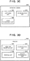
- the network camera 103 shown in Fig. 3C includes a capturing unit 321, a video transmission unit 322, and a communication unit 323.
- the capturing unit 321 Upon receiving an image capturing instruction including a capturing direction from the camera management system 102 via the communication unit 323, the capturing unit 321 performs capturing in the designated direction with the designated magnification using the camera.
- the video transmission unit 322 transmits the video captured by the capturing unit 321 to the camera management system 102 via the communication unit 323.
- the printer 104 shown in Fig. 3D includes a print job reception unit 331, a printing unit 332, a communication unit 333, and a status transmission unit 334.
- the print job reception unit 331 receives the print job transmitted from the workflow system 101 via the communication unit 333, and the printing unit 332 performs print output.
- the status transmission unit 334 detects a change in own device status (for example, in progress, error termination, normal termination, or waiting) if any.
- the status transmission unit 334 then transmits the status after the change, together with the job ID received with the print job (that is, the job corresponding to the change in device state) and a process ID, as an operation state notification request to the workflow system 101.
- the postprocessor 105 shown in Fig. 3E includes a processing job reception unit 351, a processing unit 352, a communication unit 353, and a status transmission unit 354.
- the processing job reception unit 351 receives the processing job transmitted from the workflow system 101 via the communication unit 353, and the processing unit 352 performs postprocessing.
- the status transmission unit 354 detects a change in own device status (for example, in progress, error termination, normal termination, or waiting) if any.
- the status transmission unit 354 then transmits the status after the change, together with the job ID received with the print job(that is, the job corresponding to the change in device state) and a process ID, as an operation state notification request to the workflow system 101.
- the DB 106 shown in Fig. 3F includes a communication unit 341, an event information management unit 342, and an operation state generating unit 343.
- the event information management unit 342 receives the event transmitted from the camera management system 102 via the communication unit 341 and manages the event as event information (to be described later).
- Table 4 illustrates an example of event information managed by the event information management unit 342.
- Event information is constituted by the detection start date and time when a preprocessing operation is started, the detection end date and time when the preprocessing operation is ended, and the device ID indicating the device by which the preprocessing operation is executed.
- the record on the first row indicates that a preprocessing operation has been done by the device with the device ID "Device_B".
- the period of the operation is from the detection start date and time "2019-11-21T10:31:00Z" to the detection end date and time "2019-11-21T10:32:00Z".
- the operation state generating unit 343 generates a screen displaying preprocessing operations by the respective devices and the device operation states from job information and event information from the workflow system 101 in accordance with an operation state screen acquisition request from a client PC (not shown).
- Fig. 4 is a flowchart for explaining a cyclic capturing method in the camera management system 102 according to this embodiment. Note that each step is implemented when the CPU 202 executes a stored control program. Note that Fig. 4 shows a processing procedure with focus on one camera. When a cyclic operation is to be performed with a plurality of cameras, the procedure shown in Fig. 4 may be concurrently executed with respect to each of the plurality of cameras.
- step S401 the cyclic operation control unit 318 transmits a job information acquisition request to the workflow system 101 via the communication unit 313, and obtains job information of all the jobs managed by the workflow system 101.
- step S402 the cyclic operation control unit 318 obtains, via the cyclic operation information management unit 317, a list of cyclic operation destinations as cyclic operation settings corresponding to a camera ID indicating a camera that performs a cyclic operation.
- step S403 the cyclic operation control unit 318 obtains cyclic operation destinations by sequentially reading out of the cyclic operation destination list obtained in step S402.
- step S404 the cyclic operation control unit 318 determines whether there is a record including "waiting" as a status among the records of the job information obtained in step S401 which include device IDs matching the capturing targets included in the cyclic operation destinations. For example, in the case of the first cyclic operation destination in the cyclic operation settings in Table 3, the device ID at the capturing target is "Device_A”. If the job information at this time is like that shown in Table 1, the cyclic operation control unit 318 determines that there is a record including "waiting" as a status (see the third row of Table 1, on which the job ID is "job_002" and the process ID is "p_001").
- step S404 Upon determining in step S404 that there is no record whose status is "waiting”, the cyclic operation control unit 318 executes step S408. In contrast to this, if there is a record whose status is "waiting", the cyclic operation control unit 318 determines that there is a possibility of performing a preprocessing operation, and executes step S405 (to be described later).
- step S405 the camera operation instruction unit 311 obtains the capturing direction of a record whose camera ID matches the device ID at the capturing target from the capturing target information (Table 2) via the capturing target information management unit 316.
- the camera operation instruction unit 311 then transmits a capturing instruction including Pan, Tilt, and Zoom operations in the capturing direction and the capturing time at the capturing target to the network camera 103 with the camera ID via the communication unit 313, and waits for the acquisition of a video.
- the capturing direction and the capturing time may be obtained from capturing target information and cyclic operation information, respectively.
- the settings include the camera ID "Cam_A”, “Device_A” as the device ID at the capturing target, and "60 sec” as the capturing time.
- the capturing target information at this time is like that shown in Table 2, the capturing direction of "Device_A” by "Cam_A” is represented by Pan “120”, Tilt “65”, and Zoom “3.2".
- the camera operation instruction unit 311 transmits, to the network camera "Cam_A", a video capturing instruction designating movement to the capturing target represented by Pan “120”, Tilt “65”, and Zoom "3.2” and 60-sec capturing, and waits for the acquisition of a video.
- the capturing unit 321 of the network camera 103 that has received the capturing instruction moves the camera in the operating direction instructed from the camera operation instruction unit 311 and captures a video for the capturing time.
- the video transmission unit 322 transmits the captured video to the camera management system 102
- the video reception unit 312 of the camera management system 102 receives the captured video.
- the video transmission unit 322 may transmit a captured video during capturing.
- the video analysis unit 314 obtains an analysis processing target in the cyclic operation settings from the cyclic operation information management unit 317, and analyzes the captured video in accordance with the analysis processing target. For example, in the case of "human detection”, the video analysis unit 314 analyzes whether a human is reflected in the captured video. In the case of "detection of lighting of lamp”, the video analysis unit 314 analyzes whether the control lamp is lighted and whether a preprocessing operation has been executed. The video analysis unit 314 may detect the lighting of the lamp by detecting a bright point and may detect a human by collating a feature point or movement in an image with a pattern. Obviously, the video analysis unit 314 may perform such detection by other methods.
- a limited area including the position in a video may be set as a detection target area.
- a limited area including the position may be detected. If a preprocessing operation is detected, the detection date and time is transmitted as event information to the DB 106 in step S407.
- step S407 the event transmission unit 315 transmits a device ID as a capturing target and the detection start date and time and detection end date and time of the preprocessing operation detected by the video analysis in step S406 as event information to the DB 106 via the communication unit 313.
- the detection start date and time and the detection end date and time may be specified in one capturing chance (that is, a period in which a target device is captured).
- the detection start date and time may be a period in which a detection target human or the lighting of a detection target lamp appears in a video as a result of video analysis. If a detection target is detected at the start time of capturing, the capturing start period may be set as the detection start date and time.
- the detection end date and time may be a period in which the detection target disappears from the video as a result of video analysis. If the detection target is detected at the end time of capturing, the capturing end date and time may be set as the detection end date and time.
- step S408 the cyclic operation control unit 318 determines whether a next cyclic operation destination can be obtained from the cyclic operation settings. Assume that no cyclic operation destination can be obtained. In this case, if, for example, cyclic capturing is completed at all three cyclic operation destinations in the case of Table 3, the process shifts to step S409. In contrast to this, if a cyclic operation destination can be obtained in step S408, that is, processing is not completed at all the cyclic operation destinations, the process returns to step S403.
- step S409 the camera operation instruction unit 311 determines whether it has received a cyclic capturing end instruction. If YES in step S409, the camera operation instruction unit 311 ends the processing. If NO in step S409, the process returns to step S401 to repeat cyclic capturing.
- the camera management system 102 performs cyclic capturing with the network camera 103.
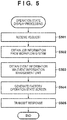
- Fig. 5 is a flowchart in which the DB 106 generates an operation state screen concerning a printing factory.
- step S501 the operation state generating unit 343 of the DB 106 receives an operation state screen generation request from a client PC (not shown) via the communication unit 341.
- step S502 the operation state generating unit 343 obtains job information from the workflow system 101.
- the job information includes device IDs, start dates and times, and end dates and times. This information indicates a specific time zone in which each device has operated.
- the operation state generating unit 343 obtains event information via the event information management unit 342.
- the event information includes detection start dates and times, detection end dates and times, and device IDs. This information indicates a specific time zone in which each device has performed a preprocessing operation.
- step S504 the operation state generating unit 343 generates an operation state screen 600 (to be described later).
- step S505 the operation state generating unit 343 transmits the operation state screen as a response to a client PC. In the above manner, the DB 106 generates an operation state screen.
- Fig. 6 shows an example of the operation state screen 600 generated by the operation state generating unit 343 in step S504 in Fig. 5 .
- An area 601 is a device ID display portion.
- a time line 602 is a time line indicating a time zone in which each device has performed a preprocessing operation and is generated from the event information obtained in step S503.
- a time line 603 is a time line indicating a device operation time zone in each device, and is generated from the event information obtained in step S502.
- a time indicating a preprocessing operation of an event that can be obtained from event information is discrete. This is because the camera management system 102 divides capturing of a device by a predetermined time, and hence there are time zones in which no capturing is performed.
- the operation state generating unit 343 specifies a plurality of preprocessing times concerning one monitoring target device, and may ignore the interval between them as long as it falls within a predetermined time. That is, the operation state generating unit 343 may ignore a blank time within a predetermined time and regard that the preprocessing operation is continuous. This embodiment is configured to ignore a blank time within one cyclic operation time as the total capturing time in cyclic operation settings.
- This operation state screen enables the user to grasp the accurate operation state of a printing factory, including preprocessing operations as well as the operation states of devices.
- a monitoring target device is captured, and the operation state of the device and a preprocessing operation state can be detected in accordance with the state of the device or its neighboring state (status).
- setting a device for which preprocessing may have been performed that is, a device in a waiting state, as cyclic observation target makes it possible to efficiently perform monitoring without a monitoring time on a device for which preprocessing has not likely been performed.
- this embodiment will exemplify a case in which capturing is more efficiently performed by determining, based on the status of preprocessing in a process of interest, whether a capturing target device is to be captured. Note that a description of the same part as that of the first embodiment will be omitted.
- Fig. 7 is a flowchart for explaining a cyclic capturing method in a camera management system 102 according to this embodiment. Steps S701 to S704 are respectively the same as steps S401 to S404, and hence a description of them will be omitted.
- step S704 If there is a record with the status "waiting" in step S704, it is determined that there is a possibility that a preprocessing operation is performed, and step S705 is executed. In this case, in step S704, the record with the status "waiting" is a reference process record.
- a cyclic operation control unit 318 obtains a record of job information including a job ID matching a reference process record and preceding the reference process record. Assume that in this embodiment, whether a given process is a previous process can be discriminated by comparing the magnitudes of the process IDs. The cyclic operation control unit 318 determines whether the status of the obtained record of the previous process is "waiting".
- step S705 If it is determined in step S705 that the status is "waiting”, the process branches to step S709. If the status is "in progress” or "normal termination", the processing in step S706 is executed. In this case, if there are a plurality of processes before the reference process and if the status of one of the processes is "waiting", "waiting" may be determined in step S705. Steps S706 to S710 are respectively the same as steps S405 to S409, and hence a description of them will be omitted.
- Cyclic capturing can be skipped for even a device for which the status is determined as "waiting" in step S705 in Fig. 7 and which is determined as a capturing target in step S704 depending on the status in a process before a process of interest. Reducing capturing for which a preprocessing operation is not likely to be performed can lead to more efficient capturing.
- the first and second embodiments have exemplified the methods for efficiently obtaining information about preprocessing operations. For this reason, according to the first and second embodiments, no capturing is performed if it is determined in step S404 that all the statuses of job information are "normal termination", that is, no capturing is performed for a device that is not planned to be operated.
- the third embodiment described below is an embodiment that can improve productivity, including postprocessing operations, by also efficiently obtaining information about postprocessing operations.
- Some device is configured to perform an operation as a postprocessing operation even after the completion of all jobs depending on the type of postprocessor.
- a chip receptor cleaning operation is such an operation.
- This embodiment will exemplify a case in which setting a device, as a capturing target, from which an event is to be detected even after the completion of all operation jobs will also obtain information about postprocessing operations. Note that a description of the same part as that of the second embodiment will be omitted.
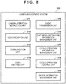
- Fig. 8 shows the software configuration of a camera management system 102 according to this embodiment.
- the camera management system 102 includes a camera operation instruction unit 311, a video reception unit 312, a communication unit 313, a video analysis unit 314, an event transmission unit 315, a capturing target information management unit 316, a cyclic operation information management unit 317, a cyclic operation control unit 318, and a device information management unit 319.
- Table 5 illustrates an example of the device information managed by the device information management unit 319.
- Table 5 Device ID Device Type Device_A printer Device_B cutting machine Device_ C bookbinding machine
- Device information is constituted by device IDs for uniquely identifying a printer 104 and a postprocessor 105 and device types such as a printer, a cutting machine, and a bookbinding machine.
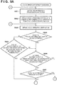
- Figs. 9A and 9B show a flowchart for explaining a cyclic capturing method in the camera management system 102 according to this embodiment. Steps S901 to S903 are respectively the same as steps S701 to S703, and hence a description of them will be omitted.
- step S904 When cyclic operation settings can be obtained in step S903, the processing in step S904 (to be described later) is executed.
- the cyclic operation control unit 318 obtains a device type of device information which matches the device ID of a capturing target included in cyclic operation settings via the device information management unit 319, and discriminates whether the device is a printer. In this embodiment, the processing to be performed is switched depending on whether a given device type is a printer. However, the device type may be other than a printer.
- the cyclic operation control unit 318 executes the processing in step S906.
- the cyclic operation control unit 318 determines in step S905 whether all the statuses of information of the job information obtained in step S901 which the device IDs of capturing targets included in cyclic operation settings match are "normal termination".
- Devices other than a printer include, for example, postprocessing apparatuses.
- step S905 if, for example, the device ID at the capturing target included in the cyclic operation settings is "Device_B" and if the job information is like that illustrated in Table 1, the cyclic operation control unit 318 determines that all the statuses are "normal termination”. Upon determining in step S905 that all the statuses are "normal termination", the cyclic operation control unit 318 executes the processing in step S908 (to be described later). If NO in step S905, the cyclic operation control unit 318 executes the processing in step S906. Steps S906 to S912 are respectively the same as steps S704 to S710, and hence a description of them will be omitted.
- step S904 even if it is determined in steps S904 and S905 that capturing is to be continued even for a device whose statuses are all "normal termination", for example, a postprocessor, continuing capturing can reduce the overlooking of changes in operation state.
- a capturing target device is a printer
- the process branches to step S905 if the device is other than a printer.
- it may be determined in step S904 whether a capturing target device is a device that requires a post-operation after processing, for example, a cutting machine, and the process may branch to step S905 if the capturing target device is the corresponding device.
- This configuration makes it possible to continue monitoring even after the completion of a job concerning a device that requires a post-operation.
- Embodiment(s) of the present invention can also be realized by a computer of a system or apparatus that reads out and executes computer executable instructions (e.g., one or more programs) recorded on a storage medium (which may also be referred to more fully as a 'non-transitory computer-readable storage medium') to perform the functions of one or more of the above-described embodiment(s) and/or that includes one or more circuits (e.g., application specific integrated circuit (ASIC)) for performing the functions of one or more of the above-described embodiment(s), and by a method performed by the computer of the system or apparatus by, for example, reading out and executing the computer executable instructions from the storage medium to perform the functions of one or more of the above-described embodiment(s) and/or controlling the one or more circuits to perform the functions of one or more of the above-described embodiment(s).
- computer executable instructions e.g., one or more programs
- a storage medium which may also be referred to more fully as
- the computer may comprise one or more processors (e.g., central processing unit (CPU), micro processing unit (MPU)) and may include a network of separate computers or separate processors to read out and execute the computer executable instructions.
- the computer executable instructions may be provided to the computer, for example, from a network or the storage medium.
- the storage medium may include, for example, one or more of a hard disk, a random-access memory (RAM), a read only memory (ROM), a storage of distributed computing systems, an optical disk (such as a compact disc (CD), digital versatile disc (DVD), or Blu-ray Disc (BD)TM), a flash memory device, a memory card, and the like.
- a monitoring system comprises a monitoring control apparatus and an image capturing unit.
- the monitoring control apparatus (102) comprises a saving unit (317) for saving a capturing order of devices, a holding unit (316) for holding a state of a device, a controller (318) for specifying a target device according to the capturing order and capture the specified target device, a detection unit (314) for detecting an event associated with the target device based on the captured video, and a unit (315) for transmitting the detected event to an information processing apparatus.
- the control means specifies a target device in accordance with the capturing order and, if there is no job in which a state of the specified target device is a waiting state, specifies the next device as a target device.
Landscapes
- Engineering & Computer Science (AREA)
- Business, Economics & Management (AREA)
- Human Resources & Organizations (AREA)
- Theoretical Computer Science (AREA)
- Physics & Mathematics (AREA)
- General Physics & Mathematics (AREA)
- Strategic Management (AREA)
- Entrepreneurship & Innovation (AREA)
- Economics (AREA)
- Tourism & Hospitality (AREA)
- Human Computer Interaction (AREA)
- General Business, Economics & Management (AREA)
- Marketing (AREA)
- General Engineering & Computer Science (AREA)
- Operations Research (AREA)
- Quality & Reliability (AREA)
- Multimedia (AREA)
- Development Economics (AREA)
- Educational Administration (AREA)
- Game Theory and Decision Science (AREA)
- Data Mining & Analysis (AREA)
- Signal Processing (AREA)
- Computational Linguistics (AREA)
- Software Systems (AREA)
- Health & Medical Sciences (AREA)
- General Health & Medical Sciences (AREA)
- Primary Health Care (AREA)
- Studio Devices (AREA)
- Management, Administration, Business Operations System, And Electronic Commerce (AREA)
Abstract
Description
- The present invention relates to a monitoring control apparatus, a monitoring control method, a monitoring system, and a medium which are associated with the collection of printing factory operation statuses by, for example, a network camera.
- Currently, demands have been raised to collect and analyze device operation states and operation execution states of workers in a printing factory and use the obtained information for improvement activities for productivity improvement. A printer used in a printing factory can collect information about the operation state of a device and notify the collected information to a workflow system as a management system via a network. However, operation states associated with preprocessing operations and postprocessing operations associated with device operations cannot be automatically collected via the printer. Examples of preprocessing operations include confirmation of operation instructions and data, preparation of a device and paper, and test printing. Example of postprocessing operations include product inspection and checkup with instructions.
- There has been proposed a mechanism for inputting, via a mobile terminal, operation information such as start and end operations concerning these operations about which no operation information can be obtained via a network, transmitting the input information to an information collecting server, and holding the information in the server (see Japanese Patent Laid-Open No.
2018-81713 - There may be a method of collecting information about operation states in a printing factory by operation monitoring with a network camera. A camera connected to a network captures indications on the control panels of a printer and a postprocessor, the lighting state of a pilot lamp, and the state of a worker around a device, detects changes in operation state, and collects corresponding information as events.
- Assume that a plurality of devices are to be cyclically captured with a network camera to collect information about operation states. In this case, while a given device is captured, information about the operation state of another device cannot be collected. On the other hand, there are demands for the management of productivity including preprocessing operations, and hence there is high necessity to collect information about preprocessing operations that cannot be collected from a printer. Accordingly, there is a problem that information about the operation states of devices, including information about preprocessing operations, cannot be efficiently collected by only repeating cyclic capturing of a plurality of devices. More specifically, if an event such as a preprocessing operation with a device has occurred at the timing at which no capturing is performed, any change in operation state cannot be detected until the next timing of cyclic capturing.
- The present invention more quickly detects a change in operation state by switching capturing targets in accordance with the statuses of devices to be observed.
- The present invention in its first aspect provides a monitoring control apparatus as specified in
claims 1 to 7. - The present invention in its second aspect provides a monitoring system as specified in claim 8.
- The present invention in its third aspect provides a computer readable medium as specified in claim 9.
- The present invention in its fourth aspect provides a monitoring control method as specified in claim 10.
- According to the present invention, a change in operation state can be more quickly detected by switching capturing targets in accordance the statues of devices to be observed.
- Further features of the present invention will become apparent from the following description of exemplary embodiments with reference to the attached drawings.
-
-
Fig. 1 is a block diagram showing the overall configuration of an event collection system according to an embodiment; -
Figs. 2A, 2B, and 2C are block diagrams showing the hardware configuration of this embodiment; -
Figs. 3A to 3F are block diagrams showing the software configuration of this embodiment; -
Fig. 4 is a flowchart for explaining a cyclic capturing method according to this embodiment; -
Fig. 5 is a flowchart for explaining an operation state screen generating method according to this embodiment; -
Fig. 6 is a view showing an example of an operation state screen according to this embodiment; -
Fig. 7 is a flowchart for explaining a cyclic capturing method according to the second embodiment; -
Fig. 8 is a block diagram showing the software configuration of acamera management system 102 according to the third embodiment; and -
Figs. 9A and9B show a flowchart for explaining a cyclic capturing method according to the third embodiment. - Hereinafter, embodiments will be described in detail with reference to the attached drawings. Note, the following embodiments are not intended to limit the scope of the claimed invention. Multiple features are described in the embodiments, but limitation is not made to an invention that requires all such features, and multiple such features may be combined as appropriate. Furthermore, in the attached drawings, the same reference numerals are given to the same or similar configurations, and redundant description thereof is omitted.
-
Fig. 1 is a block diagram showing the configuration of an event collection system according to this embodiment. The event collection system includes aworkflow system 101, acamera management system 102, anetwork camera 103, aprinter 104, apostprocessor 105, and a DB 106 which are configured to be communicable with each other via anetwork 100. In this case, theprinter 104 is network-connected to theworkflow system 101. The embodiment will exemplify a case in which there are a plurality ofpostprocessors 105 that perform postprocessing (edge trimming, bookbinding, and the like) after printing, and the respective postprocessors are network-connected. Note, however, that this system may include a plurality ofprinters 104 and may not include a plurality ofpostprocessors 105. The network is, for example, a so-called communication network implemented by a LAN such as the Internet, WAN, telephone line, or the like, and may be at least capable of transmitting and receiving data. Note that the event collection system can be regarded as a monitoring system that monitors devices to be observed. - The
workflow system 101 is a system that manages printing by theprinter 104 and postprocessing by thepostprocessor 105, and manages job information including print data, print settings, device settings of postprocessors, and process information which are used for order production. In addition, theworkflow system 101 receives and manages device operation states and process start and end instructions from theprinter 104 and thepostprocessor 105. - The
workflow system 101 may be implemented by programs executed by an information processing apparatus. Theworkflow system 101 generates a print job and a postprocessing job to be transmitted to devices connected via the network based on information such as document data as source data, a format (print settings), and postprocessing settings, and transmits the jobs to the respective devices. In addition, theworkflow system 101 generates instructions for instructing a processing procedure and presents the instructions as a printed product data to the operator. The operator makes preparations for printing and postprocessing by each device, that is, preprocessing operations, in accordance with the instructions and causes each device to execute a target process. The preprocessing operations include, for example, moving an output from a front-stage device in accordance with instructions and placing the output at a predetermined position on a next-stage device. Note that in this embodiment, a series of processes up to finishing one document into a printed product is called a job, and the unit of processing included in the job is called a process. However, when a given process is executed by a printer or postprocessor, operation instruction information generated by a workflow system concerning the process or processing based on the operation instruction information is sometimes called a "job". For example, such jobs include a print job and a processing job by a postprocessor. - The
camera management system 102 manages a plurality ofnetwork cameras 103. Thecamera management system 102 instructs thenetwork cameras 103 to perform capturing and receives the captured videos. In addition, thecamera management system 102 detects the presence/absence of preprocessing operations for the respective devices, including theprinter 104 and thepostprocessor 105, from the received videos, and transmits the corresponding information as events to theDB 106. Thecamera management system 102 may be implemented by the programs executed by an information processing apparatus. The camera management system controls the monitoring function implemented by the monitoring control system, and hence can also be called a monitoring control apparatus. A monitoring control method is executed by the processing executed by the monitoring control apparatus. - The
network camera 103 is a camera capable of zooming which is mounted on a camera platform whose capturing direction can be controlled by pan and tilt operations in accordance with instructions from the camera management system. In addition, thenetwork camera 103 starts capturing, transmits a captured image, and finishes capturing in accordance with instructions from the camera management system. - The
printer 104 receives print data and print settings from theworkflow system 101 and performs printing. Accompanying such operations, theprinter 104 transmits, to theworkflow system 101, its own device states (such as in progress, normal termination, error termination, and waiting state) together with information that can specify a job and a process. Thepostprocessor 105 receives the device settings of a postprocessing device from theworkflow system 101 and performs postprocessing. Accompanying such operations, thepostprocessor 105 transmits, to theworkflow system 101, its own device states (such as in progress, normal termination, error termination, and standby state) together with information that can specify a job and a process. TheDB 106 receives and holds events from thecamera management system 102. TheDB 106 also generates an image that allows checking of the operation state of a printing factory from job information and events from theworkflow system 101 in accordance with a request from a client PC (not shown). -
Fig. 2A is a block diagram showing the hardware configurations of theworkflow system 101, thecamera management system 102, and theDB 106 inFig. 1 . - A
user interface 201 allows the user to input and output information using a display, keyboard, mouse, touch panel, and the like. Anetwork interface 203 is connected to thenetwork 100 such as a LAN to communicate with other computers and network devices. Incorporated programs and data are recorded in aROM 204. ARAM 205 is a temporary storage area. Asecondary storage device 206 is a secondary storage typified by an HDD. ACPU 202 executes programs read out from theROM 204, theRAM 205, thesecondary storage device 206, and the like. Each unit is connected via abus 207. -
Fig. 2B is a block diagram showing the hardware configuration of thenetwork camera 103 inFig. 1 . Auser interface 211 allows connection and operation from another computer via the remote shell. Anetwork interface 213 connects to a network such as a LAN to communicate with another computer or network device. Incorporated programs and data are recorded in aROM 214. ARAM 215 is a temporary memory area. - A
secondary storage device 216 is a secondary storage typified by an HDD. ACPU 212 executes programs read out from theROM 214, theRAM 215, thesecondary storage device 216, and the like. Animage capturing unit 217 includes a CCD and stores the videos obtained by capturing images of imaging targets in thesecondary storage device 216. Each unit is connected via abus 218. -
Fig. 2C is a block diagram showing the hardware configuration of theprinter 104 inFig. 1 . Auser interface 221 allows the user to input and output information by using a display, keyboard, touch panel, and the like. Anetwork interface 223 is connected to thenetwork 100 such as a LAN to communicate with other computers and network devices. Incorporated programs and data are recorded in aROM 224. ARAM 225 is a temporary storage area. Asecondary storage device 226 is a secondary storage typified by an HDD. ACPU 222 executes programs read out from theROM 224, theRAM 225, thesecondary storage device 226, and the like. Aprint engine 227 prints data on paper (sheet). Each unit is connected via abus 228. Thepostprocessor 105 may have a configuration obtained by replacing theprint engine 227 of the configuration inFig. 2C with a device for postprocessing. -
Figs. 3A to 3F show the software configurations of theworkflow system 101, thecamera management system 102, thenetwork camera 103, theprinter 104, thepostprocessor 105, and theDB 106 shown inFig. 1 . The operations of these components will be described below. The CPU implements these operations by executing programs saved in the memories of the respective devices. - The
workflow system 101 shown inFig. 3A includes ajob management unit 301, acommunication unit 302, and a printjob transmission unit 303. Thejob management unit 301 of theworkflow system 101 manages, as job information, information about a production process for producing an ordered product. Table 1 illustrates an example of part of job information managed by thejob management unit 301. For the sake of description, this table shows a case in which there are three jobs. Job information is often information about many jobs to be processed in a given day.Table 1 Job ID Process ID Device ID Status Start Date and Time End Date and Time job_001 p_001 Device_A in progress 2019-11-21T 11:50:00Z job_001 p_ 002 Device_ C waiting job_002 p_001 Device_A waiting job_003 p_001 Device_B normal termination 2019-11-21 T 11:00:00Z 2019-11-21T 11:20:00Z - Job information is a data table for managing production processes and production states of ordered products managed by the
workflow system 101, and is constituted by "job ID", "process ID", "device ID", "status", "start date and time", and "end date and time". - "Job ID" is an ID for identifying an ordered product managed by the
workflow system 101, and is constituted by a plurality of process IDs (to be described later). "Process ID" is an ID for uniquely identifying an operation process constituting a job, including printing by theprinter 104 and bookbinding, cutting, and the like by thepostprocessor 105. Processes are sequenced, and the order of the processes can be discriminated by comparing the magnitudes of the process IDs in this embodiment. According to the example illustrated by Table 1, there are jobs for producing three ordered products. The job "job_001" is constituted by the processes "p_001" and "p_002" in this order, and the remaining jobs each are constituted by a single process. - "Device ID" includes IDs for uniquely identifying devices as the
printer 104 and thepostprocessor 105 which are used in an operation process. "Status" represents the execution state of an operation process. In this embodiment, "status" includes "waiting" as a state before the start of an operation process, "in progress" as an operating state of each of theprinter 104 and thepostprocessor 105, and "normal termination" as a state after the completion of the operation process. However, "status" may include other statuses. - "Start date and time" is the operation start date and time of an operation process, and "end date and time" is the operation end date and time of the operation process. Such pieces of information are added as the above status is changed in accordance with a device operation state notification request from the printer 104 (to be described later) or a client PC (not shown).
- The
job management unit 301 receives a device operation state notification request including a device ID, a device operation state, and a process ID from theprinter 104 or a client PC (not shown). Thejob management unit 301 then updates the status of the job information, the start date and time, and the end date and time in accordance with the contents of the received device operation state notification request. - For example, the
printer 104 receives a print job including the job ID "job_001" and the process ID "p_001" from theworkflow system 101, and executes print processing. Upon starting the print processing, theprinter 104 detects a change in the device state of theprinter 104 itself as an event. Theprinter 104 transmits a device operation state notification request including the device ID "Device A", the job ID "job_001", the process ID "p_001", and the device operation state "printing" in accordance with the event. At this time, thejob management unit 301 searches the job information for a record matching the job ID and the process ID. If the status of the corresponding record is "waiting", thejob management unit 301 regards that the operation process proceeds to an operation state, and changes the status of the record to "in progress". In addition, thejob management unit 301 sets the request reception time as the time when the status is changed to "in progress" to the start date and time. If there is no corresponding record, thejob management unit 301 adds a new record and registers the value of each item of the received information. - Upon completion of print processing, the
printer 104 transmits a device operation state notification request including the device ID "Device_A" of theprinter 104 itself, the job ID "job_001", the process ID "p_001", and the device operation state "end of printing" in accordance with the event. At this time, thejob management unit 301 searches the job information for a record matching the job ID and the process ID. If the status of the record is "in progress", regarding that the operation process is set in a completion state, thejob management unit 301 changes the status of the record to "normal termination". In addition, thejob management unit 301 sets the request reception time as the time when the status is changed to "normal termination" to the end date and time. - Like the
printer 104, thepostprocessor 105 transmits an operation state notification request via the network in accordance with the occurrence of an event. Although this embodiment exemplifies a case in which thepostprocessor 105 is connected to the network, the present invention is also applicable to even thepostprocessor 105 that cannot transmit an operation state notification request via the network. When using thepostprocessor 105 that is not network-connected, the worker generates and transmits an operation state notification request from a tablet or client PC (not shown). - In addition, the
job management unit 301 receives job information acquisition requests from thecamera management system 102 and theDB 106 and transmits job information as responses. - The print
job transmission unit 303 issues a print instruction by transmitting print data as a print job, together with a job ID and a process ID, to theprinter 104 via thecommunication unit 302. A processingjob transmission unit 304 issues a processing instruction by transmitting the device settings of a postprocessor as a processing job, together with a job ID and a process ID, to thepostprocessor 105 via thecommunication unit 302. - The
camera management system 102 shown inFig. 3B includes a cameraoperation instruction unit 311, avideo reception unit 312, acommunication unit 313, avideo analysis unit 314, anevent transmission unit 315, a capturing targetinformation management unit 316, a cyclic operationinformation management unit 317, and a cyclicoperation control unit 318. - The camera
operation instruction unit 311 issues a capturing instruction to thenetwork camera 103 via thecommunication unit 313. Thevideo reception unit 312 receives the video captured by thenetwork camera 103, that is, the captured video. Thevideo analysis unit 314 performs video analysis on the received captured video, such as human detection and detection of the lighting of a device control lamp, and determines a preprocessing operation state to determine whether a preprocessing operation is in progress. Theevent transmission unit 315 transmits the determination result on the preprocessing operation state and the device ID and time (to be described later) as an event to theDB 106 via thecommunication unit 313. - Table 2 illustrates an example of the capturing target information managed by the capturing target
information management unit 316.Table 2 Camera ID Capturing target Device ID Capturing Direction (Pan, Tilt, Zoom) Cam_ A Device_A 120,65,3.2 Cam_ A Device_B 55,23,2.5 Cam_ A Device_ C 356,24,1 - Capturing target information is a data table for managing the
network camera 103 and capturing target devices managed by thecamera management system 102, and is constituted by "camera ID", "capturing target device ID", and "capturing direction". - "Camera ID" is an ID for uniquely identifying the
network camera 103 managed by thecamera management system 102. "Capturing direction" holds the values of "Pan" (rotational angle), "Tilt" (tilt angle), and "Zoom" (enlargement/reduction) as capturing parameter information of a network camera. "Capturing target device ID" is an ID for uniquely identifying a device such as theprinter 104 or thepostprocessor 105 captured in the corresponding capturing direction by the camera with the corresponding ID. "Capturing target information" is set by the operator for each associated camera at the time of movement, installation, or removal of a network camera or device to be monitored, and may be saved in the cyclicoperation control unit 318. - When a specific device is to be captured by a specific camera, the
camera management system 102 obtains a capturing direction from a record in which the camera ID of the capturing target information matches the capturing target device ID. Thecamera management system 102 can obtain a video of a desired device by performing Pan, Tilt, and Zoom operations in the capturing direction obtained for thenetwork camera 103 with the corresponding camera ID and issuing a capturing instruction. - Table 3 illustrates an example of cyclic operation information managed by the cyclic operation
information management unit 317.Table 3 Camera_ID Cyclic Operation Settings Cam_A [Device_ A, human detection, 60 sec] [Device_ B, detection of lighting of lamp, 60 sec] [Device_C, human detection, 60 sec] - Cyclic operation information is constituted by the
network camera 103 managed by thecamera management system 102 and cyclic operation settings including capturing target devices and event detection processing. Cyclic operation information is information indicating the capturing order of target devices, detection targets, and capturing times. "Camera ID" is an ID for uniquely identifying thenetwork camera 103 managed by thecamera management system 102. "Cyclic operation settings" is a list indicating the order of capturing processing (or monitoring processing), including combinations each having a device ID as the capturing target of the network camera 103 (that is, a monitoring target), video analysis processing of detecting a preprocessing operation from a captured video, and a capturing time. - Video analysis processing is the processing of determining that the time in which a human is detected in a video is a preprocessing operation time in the case of, for example, "human detection". In the case of "detection of lighting of lamp", video analysis processing is the processing of determining that the time in which a lamp such as a device cover open/close state lamp is lighted. Video analysis processing in cyclic operation settings is information designating the execution of the processing of detecting a detection target from video information. A capturing time is information designating the time in which a device to be monitored is captured. Elements included in a list of cyclic operation settings will be referred to as cyclic operation destinations hereinafter. Cyclic operation information may be set in advance and saved in the cyclic
operation control unit 318. - In the case of Table 3, cyclic operation settings concerning the camera indicated by "Cam_A" are registered. According to Table 3, cyclic operation settings for the execution of cyclic capturing and the detection of preprocessing operations concerning three devices, namely the device "Device_A", the device "Device_B", and the device "Device_C", in this order are associated with the camera ID "Cam_A".
- The settings at the first cyclic operation destination include a capturing and analysis method of capturing the device "Device_A" for 60 sec, specifying the time in which a human is detected from the video, and determining the specified time as a preprocessing operation time. The settings at the next cyclic operation destination include a capturing and analysis method of capturing the device "Device_B" for 60 sec, specifying the time in which a lamp in the video is lighted, and determining the specified time as a preprocessing operation time. The settings at the last cyclic operation destination include a capturing and analysis method of capturing the device "Device_C" for 60 sec, specifying the time in which a human is detected from the video, and determining the specified time as a preprocessing operation time. Cyclic capturing with Cam A is performed by sequentially capturing these cyclic operation destinations in accordance with the cyclic operation information and analyzing the obtained videos. That is, the operation of sequentially capturing targets in accordance with cyclic operation information will also be referred to as a cyclic operation. The operation of analyzing a video and detecting a target may also be referred to as a cyclic operation.
- In principle, the cyclic
operation control unit 318 controls capturing of a monitoring target with thenetwork camera 103 and video analysis in accordance with cyclic operation settings. In addition, the cyclicoperation control unit 318 obtains job information from theworkflow system 101 and determines whether to perform capturing of a device at the cyclic operation destination of the cyclic operation settings of cyclic operation information and analysis of a video. That is, control is performed to skip capturing and video analysis on even a device for which cyclic operation settings designate that capturing and video analysis are to be performed in accordance with job information. - The
network camera 103 shown inFig. 3C includes acapturing unit 321, avideo transmission unit 322, and acommunication unit 323. Upon receiving an image capturing instruction including a capturing direction from thecamera management system 102 via thecommunication unit 323, the capturingunit 321 performs capturing in the designated direction with the designated magnification using the camera. Thevideo transmission unit 322 transmits the video captured by the capturingunit 321 to thecamera management system 102 via thecommunication unit 323. - The
printer 104 shown inFig. 3D includes a printjob reception unit 331, aprinting unit 332, acommunication unit 333, and astatus transmission unit 334. The printjob reception unit 331 receives the print job transmitted from theworkflow system 101 via thecommunication unit 333, and theprinting unit 332 performs print output. In addition, thestatus transmission unit 334 detects a change in own device status (for example, in progress, error termination, normal termination, or waiting) if any. Thestatus transmission unit 334 then transmits the status after the change, together with the job ID received with the print job (that is, the job corresponding to the change in device state) and a process ID, as an operation state notification request to theworkflow system 101. - The
postprocessor 105 shown inFig. 3E includes a processingjob reception unit 351, aprocessing unit 352, acommunication unit 353, and astatus transmission unit 354. The processingjob reception unit 351 receives the processing job transmitted from theworkflow system 101 via thecommunication unit 353, and theprocessing unit 352 performs postprocessing. In addition, thestatus transmission unit 354 detects a change in own device status (for example, in progress, error termination, normal termination, or waiting) if any. Thestatus transmission unit 354 then transmits the status after the change, together with the job ID received with the print job(that is, the job corresponding to the change in device state) and a process ID, as an operation state notification request to theworkflow system 101. - The
DB 106 shown inFig. 3F includes acommunication unit 341, an eventinformation management unit 342, and an operationstate generating unit 343. The eventinformation management unit 342 receives the event transmitted from thecamera management system 102 via thecommunication unit 341 and manages the event as event information (to be described later). Table 4 illustrates an example of event information managed by the eventinformation management unit 342.Table 4 Detection Start Date and Detection End Date and Device ID Time Time 2019-11-21T10:31:00Z 2019-11-21T10:32:00Z Device_B 2019-11-21T10:34:00Z 2019-11-21T10:35:00Z Device_B 2019-11-21T10:41:00Z 2019-11-21T10:42:00Z Device_B 2019-11-21T10:44:00Z 2019-11-21T10:45:00Z Device_B 2019-11-21T11:46:00Z 2019-11-21T11:46:45Z Device_A - Event information is constituted by the detection start date and time when a preprocessing operation is started, the detection end date and time when the preprocessing operation is ended, and the device ID indicating the device by which the preprocessing operation is executed.
- According to Table 4, for example, the record on the first row indicates that a preprocessing operation has been done by the device with the device ID "Device_B". The period of the operation is from the detection start date and time "2019-11-21T10:31:00Z" to the detection end date and time "2019-11-21T10:32:00Z".
- The operation
state generating unit 343 generates a screen displaying preprocessing operations by the respective devices and the device operation states from job information and event information from theworkflow system 101 in accordance with an operation state screen acquisition request from a client PC (not shown). -
Fig. 4 is a flowchart for explaining a cyclic capturing method in thecamera management system 102 according to this embodiment. Note that each step is implemented when theCPU 202 executes a stored control program. Note thatFig. 4 shows a processing procedure with focus on one camera. When a cyclic operation is to be performed with a plurality of cameras, the procedure shown inFig. 4 may be concurrently executed with respect to each of the plurality of cameras. - In step S401, the cyclic
operation control unit 318 transmits a job information acquisition request to theworkflow system 101 via thecommunication unit 313, and obtains job information of all the jobs managed by theworkflow system 101. - In step S402, the cyclic
operation control unit 318 obtains, via the cyclic operationinformation management unit 317, a list of cyclic operation destinations as cyclic operation settings corresponding to a camera ID indicating a camera that performs a cyclic operation. - In step S403, the cyclic
operation control unit 318 obtains cyclic operation destinations by sequentially reading out of the cyclic operation destination list obtained in step S402. - In step S404, the cyclic
operation control unit 318 determines whether there is a record including "waiting" as a status among the records of the job information obtained in step S401 which include device IDs matching the capturing targets included in the cyclic operation destinations. For example, in the case of the first cyclic operation destination in the cyclic operation settings in Table 3, the device ID at the capturing target is "Device_A". If the job information at this time is like that shown in Table 1, the cyclicoperation control unit 318 determines that there is a record including "waiting" as a status (see the third row of Table 1, on which the job ID is "job_002" and the process ID is "p_001"). - Upon determining in step S404 that there is no record whose status is "waiting", the cyclic
operation control unit 318 executes step S408. In contrast to this, if there is a record whose status is "waiting", the cyclicoperation control unit 318 determines that there is a possibility of performing a preprocessing operation, and executes step S405 (to be described later). - In step S405, the camera
operation instruction unit 311 obtains the capturing direction of a record whose camera ID matches the device ID at the capturing target from the capturing target information (Table 2) via the capturing targetinformation management unit 316. The cameraoperation instruction unit 311 then transmits a capturing instruction including Pan, Tilt, and Zoom operations in the capturing direction and the capturing time at the capturing target to thenetwork camera 103 with the camera ID via thecommunication unit 313, and waits for the acquisition of a video. The capturing direction and the capturing time may be obtained from capturing target information and cyclic operation information, respectively. For example, in the case of the first cyclic operation destination in the cyclic operation settings in Table 3, the settings include the camera ID "Cam_A", "Device_A" as the device ID at the capturing target, and "60 sec" as the capturing time. If the capturing target information at this time is like that shown in Table 2, the capturing direction of "Device_A" by "Cam_A" is represented by Pan "120", Tilt "65", and Zoom "3.2". The cameraoperation instruction unit 311 transmits, to the network camera "Cam_A", a video capturing instruction designating movement to the capturing target represented by Pan "120", Tilt "65", and Zoom "3.2" and 60-sec capturing, and waits for the acquisition of a video. - The capturing
unit 321 of thenetwork camera 103 that has received the capturing instruction moves the camera in the operating direction instructed from the cameraoperation instruction unit 311 and captures a video for the capturing time. Upon completion of the capturing, when thevideo transmission unit 322 transmits the captured video to thecamera management system 102, thevideo reception unit 312 of thecamera management system 102 receives the captured video. Obviously, thevideo transmission unit 322 may transmit a captured video during capturing. - In step S406, the
video analysis unit 314 obtains an analysis processing target in the cyclic operation settings from the cyclic operationinformation management unit 317, and analyzes the captured video in accordance with the analysis processing target. For example, in the case of "human detection", thevideo analysis unit 314 analyzes whether a human is reflected in the captured video. In the case of "detection of lighting of lamp", thevideo analysis unit 314 analyzes whether the control lamp is lighted and whether a preprocessing operation has been executed. Thevideo analysis unit 314 may detect the lighting of the lamp by detecting a bright point and may detect a human by collating a feature point or movement in an image with a pattern. Obviously, thevideo analysis unit 314 may perform such detection by other methods. In the case of human detection, if the position of a human relative to a monitoring target device is determined in preprocessing, a limited area including the position in a video may be set as a detection target area. In the case of the detection of the lighting of the lamp, since the position of the lamp in a video can be specified in advance, a limited area including the position may be detected. If a preprocessing operation is detected, the detection date and time is transmitted as event information to theDB 106 in step S407. - In step S407, the
event transmission unit 315 transmits a device ID as a capturing target and the detection start date and time and detection end date and time of the preprocessing operation detected by the video analysis in step S406 as event information to theDB 106 via thecommunication unit 313. - Note that the detection start date and time and the detection end date and time may be specified in one capturing chance (that is, a period in which a target device is captured). For example, the detection start date and time may be a period in which a detection target human or the lighting of a detection target lamp appears in a video as a result of video analysis. If a detection target is detected at the start time of capturing, the capturing start period may be set as the detection start date and time. The detection end date and time may be a period in which the detection target disappears from the video as a result of video analysis. If the detection target is detected at the end time of capturing, the capturing end date and time may be set as the detection end date and time.
- In step S408, the cyclic
operation control unit 318 determines whether a next cyclic operation destination can be obtained from the cyclic operation settings. Assume that no cyclic operation destination can be obtained. In this case, if, for example, cyclic capturing is completed at all three cyclic operation destinations in the case of Table 3, the process shifts to step S409. In contrast to this, if a cyclic operation destination can be obtained in step S408, that is, processing is not completed at all the cyclic operation destinations, the process returns to step S403. - In step S409, the camera
operation instruction unit 311 determines whether it has received a cyclic capturing end instruction. If YES in step S409, the cameraoperation instruction unit 311 ends the processing. If NO in step S409, the process returns to step S401 to repeat cyclic capturing. - In the above manner, the
camera management system 102 performs cyclic capturing with thenetwork camera 103. -
Fig. 5 is a flowchart in which theDB 106 generates an operation state screen concerning a printing factory. - In step S501, the operation
state generating unit 343 of theDB 106 receives an operation state screen generation request from a client PC (not shown) via thecommunication unit 341. - In step S502, the operation
state generating unit 343 obtains job information from theworkflow system 101. The job information includes device IDs, start dates and times, and end dates and times. This information indicates a specific time zone in which each device has operated. - In step S503, the operation
state generating unit 343 obtains event information via the eventinformation management unit 342. The event information includes detection start dates and times, detection end dates and times, and device IDs. This information indicates a specific time zone in which each device has performed a preprocessing operation. - In step S504, the operation
state generating unit 343 generates an operation state screen 600 (to be described later). In step S505, the operationstate generating unit 343 transmits the operation state screen as a response to a client PC. In the above manner, theDB 106 generates an operation state screen. -
Fig. 6 shows an example of theoperation state screen 600 generated by the operationstate generating unit 343 in step S504 inFig. 5 . Anarea 601 is a device ID display portion. Atime line 602 is a time line indicating a time zone in which each device has performed a preprocessing operation and is generated from the event information obtained in step S503. Atime line 603 is a time line indicating a device operation time zone in each device, and is generated from the event information obtained in step S502. - A time indicating a preprocessing operation of an event that can be obtained from event information is discrete. This is because the
camera management system 102 divides capturing of a device by a predetermined time, and hence there are time zones in which no capturing is performed. - For example, in the case of Table 4, in the preprocessing operation time of "Device_B", no preprocessing operation is performed between "2019-11-21T10:32:00Z" and "2019-11-21T10:34:00Z". This indicates that there is a blank time in this time because the
network camera 103 performs cyclic capturing of another device. For this reason, the operationstate generating unit 343 specifies a plurality of preprocessing times concerning one monitoring target device, and may ignore the interval between them as long as it falls within a predetermined time. That is, the operationstate generating unit 343 may ignore a blank time within a predetermined time and regard that the preprocessing operation is continuous. This embodiment is configured to ignore a blank time within one cyclic operation time as the total capturing time in cyclic operation settings. - At this time, in the case of Table 4, assume that "Device B" has performed one preprocessing operation between "2019-11-21T10:31:00Z" and "2019-11-21T10:35:00Z". In addition, assume that another preprocessing operation has been done between "2019-11-21T10:41:00Z" and "2019-11-21T10:45:00Z". The time between these periods is regarded as a time in which no preprocessing operation has been performed. This is because the time between the periods exceeds the cyclic operation interval.
- This operation state screen enables the user to grasp the accurate operation state of a printing factory, including preprocessing operations as well as the operation states of devices.
- As described above, according to this embodiment, a monitoring target device is captured, and the operation state of the device and a preprocessing operation state can be detected in accordance with the state of the device or its neighboring state (status). In addition, setting a device for which preprocessing may have been performed, that is, a device in a waiting state, as cyclic observation target makes it possible to efficiently perform monitoring without a monitoring time on a device for which preprocessing has not likely been performed.
- In the first embodiment, if the status of the job information is "waiting" in step S404 in
Fig. 4 , a capturing target is always captured, and video analysis is performed. Even if there is a process in "waiting" status concerning a given device, when the previous process is being executed, a preprocessing operation in the "waiting" process concerning the device is rarely performed until the processing in the previous process is completed. This is because an output from the process tends to become a processing target in the next process. Accordingly, this embodiment will exemplify a case in which capturing is more efficiently performed by determining, based on the status of preprocessing in a process of interest, whether a capturing target device is to be captured. Note that a description of the same part as that of the first embodiment will be omitted. -
Fig. 7 is a flowchart for explaining a cyclic capturing method in acamera management system 102 according to this embodiment. Steps S701 to S704 are respectively the same as steps S401 to S404, and hence a description of them will be omitted. - If there is a record with the status "waiting" in step S704, it is determined that there is a possibility that a preprocessing operation is performed, and step S705 is executed. In this case, in step S704, the record with the status "waiting" is a reference process record.
- In step S705, a cyclic
operation control unit 318 obtains a record of job information including a job ID matching a reference process record and preceding the reference process record. Assume that in this embodiment, whether a given process is a previous process can be discriminated by comparing the magnitudes of the process IDs. The cyclicoperation control unit 318 determines whether the status of the obtained record of the previous process is "waiting". - If it is determined in step S705 that the status is "waiting", the process branches to step S709. If the status is "in progress" or "normal termination", the processing in step S706 is executed. In this case, if there are a plurality of processes before the reference process and if the status of one of the processes is "waiting", "waiting" may be determined in step S705. Steps S706 to S710 are respectively the same as steps S405 to S409, and hence a description of them will be omitted.
- Cyclic capturing can be skipped for even a device for which the status is determined as "waiting" in step S705 in
Fig. 7 and which is determined as a capturing target in step S704 depending on the status in a process before a process of interest. Reducing capturing for which a preprocessing operation is not likely to be performed can lead to more efficient capturing. - The first and second embodiments have exemplified the methods for efficiently obtaining information about preprocessing operations. For this reason, according to the first and second embodiments, no capturing is performed if it is determined in step S404 that all the statuses of job information are "normal termination", that is, no capturing is performed for a device that is not planned to be operated.
- The third embodiment described below is an embodiment that can improve productivity, including postprocessing operations, by also efficiently obtaining information about postprocessing operations. Some device is configured to perform an operation as a postprocessing operation even after the completion of all jobs depending on the type of postprocessor. In the case of a cutting machine, a chip receptor cleaning operation is such an operation. This embodiment will exemplify a case in which setting a device, as a capturing target, from which an event is to be detected even after the completion of all operation jobs will also obtain information about postprocessing operations. Note that a description of the same part as that of the second embodiment will be omitted.
-
Fig. 8 shows the software configuration of acamera management system 102 according to this embodiment. Thecamera management system 102 includes a cameraoperation instruction unit 311, avideo reception unit 312, acommunication unit 313, avideo analysis unit 314, anevent transmission unit 315, a capturing targetinformation management unit 316, a cyclic operationinformation management unit 317, a cyclicoperation control unit 318, and a deviceinformation management unit 319. Table 5 illustrates an example of the device information managed by the deviceinformation management unit 319.Table 5 Device ID Device Type Device_A printer Device_B cutting machine Device_ C bookbinding machine - Device information is constituted by device IDs for uniquely identifying a
printer 104 and apostprocessor 105 and device types such as a printer, a cutting machine, and a bookbinding machine. -
Figs. 9A and9B show a flowchart for explaining a cyclic capturing method in thecamera management system 102 according to this embodiment. Steps S901 to S903 are respectively the same as steps S701 to S703, and hence a description of them will be omitted. - When cyclic operation settings can be obtained in step S903, the processing in step S904 (to be described later) is executed. In step S904, the cyclic
operation control unit 318 obtains a device type of device information which matches the device ID of a capturing target included in cyclic operation settings via the deviceinformation management unit 319, and discriminates whether the device is a printer. In this embodiment, the processing to be performed is switched depending on whether a given device type is a printer. However, the device type may be other than a printer. Upon determining in step S904 that the device is a printer, the cyclicoperation control unit 318 executes the processing in step S906. Upon determining in step S904 that the device type is not a printer, the cyclicoperation control unit 318 determines in step S905 whether all the statuses of information of the job information obtained in step S901 which the device IDs of capturing targets included in cyclic operation settings match are "normal termination". Devices other than a printer include, for example, postprocessing apparatuses. - In step S905, if, for example, the device ID at the capturing target included in the cyclic operation settings is "Device_B" and if the job information is like that illustrated in Table 1, the cyclic
operation control unit 318 determines that all the statuses are "normal termination". Upon determining in step S905 that all the statuses are "normal termination", the cyclicoperation control unit 318 executes the processing in step S908 (to be described later). If NO in step S905, the cyclicoperation control unit 318 executes the processing in step S906. Steps S906 to S912 are respectively the same as steps S704 to S710, and hence a description of them will be omitted. - In this embodiment, even if it is determined in steps S904 and S905 that capturing is to be continued even for a device whose statuses are all "normal termination", for example, a postprocessor, continuing capturing can reduce the overlooking of changes in operation state. Note that it is determined in step S904 that a capturing target device is a printer, and the process branches to step S905 if the device is other than a printer. Alternatively, it may be determined in step S904 whether a capturing target device is a device that requires a post-operation after processing, for example, a cutting machine, and the process may branch to step S905 if the capturing target device is the corresponding device. This configuration makes it possible to continue monitoring even after the completion of a job concerning a device that requires a post-operation.
- Embodiment(s) of the present invention can also be realized by a computer of a system or apparatus that reads out and executes computer executable instructions (e.g., one or more programs) recorded on a storage medium (which may also be referred to more fully as a 'non-transitory computer-readable storage medium') to perform the functions of one or more of the above-described embodiment(s) and/or that includes one or more circuits (e.g., application specific integrated circuit (ASIC)) for performing the functions of one or more of the above-described embodiment(s), and by a method performed by the computer of the system or apparatus by, for example, reading out and executing the computer executable instructions from the storage medium to perform the functions of one or more of the above-described embodiment(s) and/or controlling the one or more circuits to perform the functions of one or more of the above-described embodiment(s). The computer may comprise one or more processors (e.g., central processing unit (CPU), micro processing unit (MPU)) and may include a network of separate computers or separate processors to read out and execute the computer executable instructions. The computer executable instructions may be provided to the computer, for example, from a network or the storage medium. The storage medium may include, for example, one or more of a hard disk, a random-access memory (RAM), a read only memory (ROM), a storage of distributed computing systems, an optical disk (such as a compact disc (CD), digital versatile disc (DVD), or Blu-ray Disc (BD)™), a flash memory device, a memory card, and the like.
- While the present invention has been described with reference to exemplary embodiments, it is to be understood that the invention is not limited to the disclosed exemplary embodiments. The scope of the following claims is to be accorded the broadest interpretation so as to encompass all such modifications and equivalent structures and functions.
A monitoring system is provided. The system comprises a monitoring control apparatus and an image capturing unit. The monitoring control apparatus (102) comprises a saving unit (317) for saving a capturing order of devices, a holding unit (316) for holding a state of a device, a controller (318) for specifying a target device according to the capturing order and capture the specified target device, a detection unit (314) for detecting an event associated with the target device based on the captured video, and a unit (315) for transmitting the detected event to an information processing apparatus. The control means specifies a target device in accordance with the capturing order and, if there is no job in which a state of the specified target device is a waiting state, specifies the next device as a target device.
Claims (10)
- A monitoring control apparatus (102) comprising:saving means (317) configure to save a capturing order of devices for each capturing unit;holding means (316) configure to hold, for each job, a state of a device used in the job; andcontrol means (318) configure to specify a target device in accordance with the capturing order and capture the specified target device with the capturing unit,wherein the control means specifies a target device as a next capturing target in accordance with the capturing order and, if there is no job in which a state of the specified target device is a waiting state, specifies a next device as a target device in accordance with the capturing order.
- The apparatus according to claim 1, wherein the control means further specifies a device next the target device as a capturing target in accordance with the capturing order if there is a job in which a state of the target device is a waiting state and if there is a process in a waiting state before a process executed by the target device in the job.
- The apparatus according to claim 2, wherein the control means further captures the target device with the capturing unit if the target device is a predetermined type of device and if all jobs using the target device are completed.
- The apparatus according to any one of claims 1 to 3, further comprising detection means (314) configure to receive a video obtained by capturing the target device with the capturing unit and detecting an event associated with the target device based on the video.
- The apparatus according to claim 4, wherein the detection means detects an event by detecting a predetermined target from the video.
- The apparatus according to claim 5, wherein the predetermined target includes a worker or lighting of a lamp of the target device.
- The apparatus according to any one of claims 4 to 6, further comprising means (315) configure to transmit the detected event to an information processing apparatus configured to display the event on a user interface.
- A monitoring system comprising:a monitoring control apparatus;a capturing unit configured to perform capturing in at least a capturing direction; andan information processing apparatus configured to receive the event from the monitoring control apparatus and display the event on a user interface,the monitoring control apparatus (102) comprisingsaving means (317) configure to save a capturing order of devices for each capturing unit,holding means (316) configure to hold, for each job, a state of a device used in the job,control means (318) configure to specify a target device in accordance with the capturing order and capture the specified target device with the capturing unit,detection means (314) configure to receive a video obtained by capturing the target device with the capturing unit and detecting an event associated with the target device based on the video, andmeans (315) configure to transmit the detected event to an information processing apparatus configured to display the event on a user interface, andthe control means specifies a target device as a next capturing target in accordance with the capturing order and, if there is no job in which a state of the specified target device is a waiting state, specifies a next device as a target device in accordance with the capturing order.
- A computer-readable medium storing a program instruction for causing a computer to execute an operation when the computer is executing the program, the operation including:saving a capturing order of devices for each capturing unit;holding a state of a device used in each job;specifying a target device in accordance with the capturing order and capturing the specified target device with the capturing unit; andspecifying a target device as a next capturing target in accordance with the capturing order and, if there is no job in which a state of the specified target device is a waiting state, specifying a next device as a target device in accordance with the capturing order.
- A monitoring control method executed by a monitoring control apparatus including a saving means saving a capturing order of devices for each capturing unit and a holding means configured to hold, for each job, a state of a device used in the job, the method comprising:specifying a target device in accordance with the capturing order;capturing the specified target device with the capturing unit; andspecifying a target device as a next capturing target in accordance with the capturing order and, if there is no job in which a state of the specified target device is a waiting state, specifying a next device as a target device in accordance with the capturing order.
Applications Claiming Priority (1)
| Application Number | Priority Date | Filing Date | Title |
|---|---|---|---|
| JP2020020893A JP7437960B2 (en) | 2020-02-10 | 2020-02-10 | Supervisory control device, supervisory control method, supervisory system and program |
Publications (2)
| Publication Number | Publication Date |
|---|---|
| EP3862943A1 true EP3862943A1 (en) | 2021-08-11 |
| EP3862943B1 EP3862943B1 (en) | 2025-11-26 |
Family
ID=74572693
Family Applications (1)
| Application Number | Title | Priority Date | Filing Date |
|---|---|---|---|
| EP21155977.8A Active EP3862943B1 (en) | 2020-02-10 | 2021-02-09 | Monitoring control apparatus, monitoring control method, monitoring system, and medium |
Country Status (5)
| Country | Link |
|---|---|
| US (1) | US12061829B2 (en) |
| EP (1) | EP3862943B1 (en) |
| JP (1) | JP7437960B2 (en) |
| KR (1) | KR20210102083A (en) |
| CN (1) | CN113253950A (en) |
Citations (4)
| Publication number | Priority date | Publication date | Assignee | Title |
|---|---|---|---|---|
| US20080193146A1 (en) * | 2007-02-08 | 2008-08-14 | Canon Kabushiki Kaisha | Monitoring apparatus and monitoring system for image forming apparatus and control method for monitoring apparatus and monitoring system |
| JP2015109613A (en) * | 2013-12-05 | 2015-06-11 | キヤノン株式会社 | Monitoring system, monitoring camera, monitoring method, and program |
| JP2015133020A (en) * | 2014-01-14 | 2015-07-23 | キヤノン株式会社 | Management client device, management system, management method, and program |
| JP2018081713A (en) | 2017-12-29 | 2018-05-24 | 横河電機株式会社 | Information collection system, information collection terminal device, information collection server device, and information collection method |
Family Cites Families (10)
| Publication number | Priority date | Publication date | Assignee | Title |
|---|---|---|---|---|
| US7773248B2 (en) | 2003-09-30 | 2010-08-10 | Brother Kogyo Kabushiki Kaisha | Device information management system |
| KR20080045318A (en) * | 2006-11-20 | 2008-05-23 | (주) 캐스트정보 | Surveillance system for complementary control of cameras |
| US8248641B2 (en) * | 2007-10-03 | 2012-08-21 | Ricoh Company, Limited | Network printers having distributed print jobs function and utilizing withhold printing commands |
| JP5794329B2 (en) * | 2014-02-14 | 2015-10-14 | 日本電気株式会社 | Equipment monitoring system, equipment monitoring method and equipment monitoring program |
| JP2015197846A (en) * | 2014-04-02 | 2015-11-09 | キヤノン株式会社 | Printing apparatus monitoring system, control method therefor, and program |
| US9407880B2 (en) | 2014-04-10 | 2016-08-02 | Smartvue Corporation | Systems and methods for automated 3-dimensional (3D) cloud-based analytics for security surveillance in operation areas |
| JP2016048431A (en) | 2014-08-27 | 2016-04-07 | キヤノン株式会社 | Monitoring device, device management method for monitoring device, and program |
| CN107066215B (en) * | 2016-01-07 | 2020-03-06 | 精工爱普生株式会社 | Network system, printing apparatus, information processing apparatus, and control method |
| JP6852475B2 (en) * | 2017-03-13 | 2021-03-31 | コニカミノルタ株式会社 | Image formation system, image formation method and equipment, job management method and job management program |
| JP6824838B2 (en) * | 2017-07-07 | 2021-02-03 | 株式会社日立製作所 | Work data management system and work data management method |
-
2020
- 2020-02-10 JP JP2020020893A patent/JP7437960B2/en active Active
-
2021
- 2021-02-05 KR KR1020210016500A patent/KR20210102083A/en not_active Withdrawn
- 2021-02-09 CN CN202110178262.7A patent/CN113253950A/en not_active Withdrawn
- 2021-02-09 EP EP21155977.8A patent/EP3862943B1/en active Active
- 2021-02-09 US US17/171,099 patent/US12061829B2/en active Active
Patent Citations (4)
| Publication number | Priority date | Publication date | Assignee | Title |
|---|---|---|---|---|
| US20080193146A1 (en) * | 2007-02-08 | 2008-08-14 | Canon Kabushiki Kaisha | Monitoring apparatus and monitoring system for image forming apparatus and control method for monitoring apparatus and monitoring system |
| JP2015109613A (en) * | 2013-12-05 | 2015-06-11 | キヤノン株式会社 | Monitoring system, monitoring camera, monitoring method, and program |
| JP2015133020A (en) * | 2014-01-14 | 2015-07-23 | キヤノン株式会社 | Management client device, management system, management method, and program |
| JP2018081713A (en) | 2017-12-29 | 2018-05-24 | 横河電機株式会社 | Information collection system, information collection terminal device, information collection server device, and information collection method |
Also Published As
| Publication number | Publication date |
|---|---|
| JP7437960B2 (en) | 2024-02-26 |
| US20210247943A1 (en) | 2021-08-12 |
| JP2021128378A (en) | 2021-09-02 |
| KR20210102083A (en) | 2021-08-19 |
| CN113253950A (en) | 2021-08-13 |
| EP3862943B1 (en) | 2025-11-26 |
| US12061829B2 (en) | 2024-08-13 |
Similar Documents
| Publication | Publication Date | Title |
|---|---|---|
| US20150109438A1 (en) | Management method for network system and network device, network device and control method therefor, and management system | |
| US10110453B2 (en) | Network system and device management method | |
| US9497348B2 (en) | Document output method for outputting documents associated with an event | |
| CN113805820B (en) | Inspection system, inspection equipment, and control method of inspection equipment | |
| JP6460932B2 (en) | Image processing apparatus, system, image processing apparatus control method, system control method, and program | |
| US11128776B2 (en) | Remote support system, image forming apparatus, external terminal, printer controller, methods of controlling these, and storage medium | |
| US20120317277A1 (en) | Monitoring apparatus, monitoring method, and computer-readable medium | |
| JP2013257728A (en) | Print control device, control method of print control device, and program | |
| US11782661B2 (en) | Monitoring control apparatus, monitoring control method, monitoring system, and medium | |
| US9813581B2 (en) | Improving workflow processing efficiency of information processing system, information processing method, and device via workload distribution | |
| JP2021179746A (en) | Monitoring control device, monitoring control method, monitoring system and program | |
| JP5451363B2 (en) | Image confirmation device | |
| EP3862943B1 (en) | Monitoring control apparatus, monitoring control method, monitoring system, and medium | |
| US10152697B2 (en) | Monitoring apparatus, monitoring method and non-transitory computer-readable medium | |
| JP2015197846A (en) | Printing apparatus monitoring system, control method therefor, and program | |
| JP7067797B2 (en) | Maintenance work management equipment, systems, methods, and programs | |
| JP6610050B2 (en) | Information processing apparatus, information processing method, and program | |
| JP5836718B2 (en) | Image forming apparatus, information processing method, and program | |
| JP7059036B2 (en) | Programs, information processing equipment, and information processing methods | |
| JP2021149650A (en) | Progress management system and control method therefor | |
| JP2015133020A (en) | Management client device, management system, management method, and program | |
| US20180278755A1 (en) | Image management system, image management server, and non-transitory computer readable medium | |
| EP4106306A1 (en) | Information processing apparatus, control method, and carrier medium | |
| JP2015119397A (en) | Image processing apparatus, image processing method, and program | |
| US20110090356A1 (en) | Imaging system and imaging processing method thereof |
Legal Events
| Date | Code | Title | Description |
|---|---|---|---|
| PUAI | Public reference made under article 153(3) epc to a published international application that has entered the european phase |
Free format text: ORIGINAL CODE: 0009012 |
|
| STAA | Information on the status of an ep patent application or granted ep patent |
Free format text: STATUS: THE APPLICATION HAS BEEN PUBLISHED |
|
| AK | Designated contracting states |
Kind code of ref document: A1 Designated state(s): AL AT BE BG CH CY CZ DE DK EE ES FI FR GB GR HR HU IE IS IT LI LT LU LV MC MK MT NL NO PL PT RO RS SE SI SK SM TR |
|
| STAA | Information on the status of an ep patent application or granted ep patent |
Free format text: STATUS: REQUEST FOR EXAMINATION WAS MADE |
|
| 17P | Request for examination filed |
Effective date: 20220211 |
|
| RBV | Designated contracting states (corrected) |
Designated state(s): AL AT BE BG CH CY CZ DE DK EE ES FI FR GB GR HR HU IE IS IT LI LT LU LV MC MK MT NL NO PL PT RO RS SE SI SK SM TR |
|
| STAA | Information on the status of an ep patent application or granted ep patent |
Free format text: STATUS: EXAMINATION IS IN PROGRESS |
|
| 17Q | First examination report despatched |
Effective date: 20230613 |
|
| GRAP | Despatch of communication of intention to grant a patent |
Free format text: ORIGINAL CODE: EPIDOSNIGR1 |
|
| STAA | Information on the status of an ep patent application or granted ep patent |
Free format text: STATUS: GRANT OF PATENT IS INTENDED |
|
| INTG | Intention to grant announced |
Effective date: 20250623 |
|
| RIN1 | Information on inventor provided before grant (corrected) |
Inventor name: SATO, YUICHIRO Inventor name: KANEKO, SHUHEI |
|
| GRAS | Grant fee paid |
Free format text: ORIGINAL CODE: EPIDOSNIGR3 |
|
| GRAA | (expected) grant |
Free format text: ORIGINAL CODE: 0009210 |
|
| STAA | Information on the status of an ep patent application or granted ep patent |
Free format text: STATUS: THE PATENT HAS BEEN GRANTED |
|
| AK | Designated contracting states |
Kind code of ref document: B1 Designated state(s): AL AT BE BG CH CY CZ DE DK EE ES FI FR GB GR HR HU IE IS IT LI LT LU LV MC MK MT NL NO PL PT RO RS SE SI SK SM TR |
|
| REG | Reference to a national code |
Ref country code: CH Ref legal event code: F10 Free format text: ST27 STATUS EVENT CODE: U-0-0-F10-F00 (AS PROVIDED BY THE NATIONAL OFFICE) Effective date: 20251126 Ref country code: GB Ref legal event code: FG4D |
|
| REG | Reference to a national code |
Ref country code: IE Ref legal event code: FG4D |
|
| REG | Reference to a national code |
Ref country code: DE Ref legal event code: R096 Ref document number: 602021042899 Country of ref document: DE |
|
| PG25 | Lapsed in a contracting state [announced via postgrant information from national office to epo] |
Ref country code: ES Free format text: LAPSE BECAUSE OF FAILURE TO SUBMIT A TRANSLATION OF THE DESCRIPTION OR TO PAY THE FEE WITHIN THE PRESCRIBED TIME-LIMIT Effective date: 20251126 |
|
| REG | Reference to a national code |
Ref country code: LT Ref legal event code: MG9D |
|
| PG25 | Lapsed in a contracting state [announced via postgrant information from national office to epo] |
Ref country code: NO Free format text: LAPSE BECAUSE OF FAILURE TO SUBMIT A TRANSLATION OF THE DESCRIPTION OR TO PAY THE FEE WITHIN THE PRESCRIBED TIME-LIMIT Effective date: 20260226 |
|
| PGFP | Annual fee paid to national office [announced via postgrant information from national office to epo] |
Ref country code: DE Payment date: 20260121 Year of fee payment: 6 |
|
| PG25 | Lapsed in a contracting state [announced via postgrant information from national office to epo] |
Ref country code: FI Free format text: LAPSE BECAUSE OF FAILURE TO SUBMIT A TRANSLATION OF THE DESCRIPTION OR TO PAY THE FEE WITHIN THE PRESCRIBED TIME-LIMIT Effective date: 20251126 Ref country code: AT Free format text: LAPSE BECAUSE OF FAILURE TO SUBMIT A TRANSLATION OF THE DESCRIPTION OR TO PAY THE FEE WITHIN THE PRESCRIBED TIME-LIMIT Effective date: 20251126 Ref country code: HR Free format text: LAPSE BECAUSE OF FAILURE TO SUBMIT A TRANSLATION OF THE DESCRIPTION OR TO PAY THE FEE WITHIN THE PRESCRIBED TIME-LIMIT Effective date: 20251126 |
|
| REG | Reference to a national code |
Ref country code: AT Ref legal event code: MK05 Ref document number: 1861823 Country of ref document: AT Kind code of ref document: T Effective date: 20251126 |
|
| PG25 | Lapsed in a contracting state [announced via postgrant information from national office to epo] |
Ref country code: NL Free format text: LAPSE BECAUSE OF FAILURE TO SUBMIT A TRANSLATION OF THE DESCRIPTION OR TO PAY THE FEE WITHIN THE PRESCRIBED TIME-LIMIT Effective date: 20251126 |
|
| PG25 | Lapsed in a contracting state [announced via postgrant information from national office to epo] |
Ref country code: RS Free format text: LAPSE BECAUSE OF FAILURE TO SUBMIT A TRANSLATION OF THE DESCRIPTION OR TO PAY THE FEE WITHIN THE PRESCRIBED TIME-LIMIT Effective date: 20260226 |
|
| PG25 | Lapsed in a contracting state [announced via postgrant information from national office to epo] |
Ref country code: IS Free format text: LAPSE BECAUSE OF FAILURE TO SUBMIT A TRANSLATION OF THE DESCRIPTION OR TO PAY THE FEE WITHIN THE PRESCRIBED TIME-LIMIT Effective date: 20260326 |
|
| PG25 | Lapsed in a contracting state [announced via postgrant information from national office to epo] |
Ref country code: PT Free format text: LAPSE BECAUSE OF FAILURE TO SUBMIT A TRANSLATION OF THE DESCRIPTION OR TO PAY THE FEE WITHIN THE PRESCRIBED TIME-LIMIT Effective date: 20260326 |
|
| PG25 | Lapsed in a contracting state [announced via postgrant information from national office to epo] |
Ref country code: PL Free format text: LAPSE BECAUSE OF FAILURE TO SUBMIT A TRANSLATION OF THE DESCRIPTION OR TO PAY THE FEE WITHIN THE PRESCRIBED TIME-LIMIT Effective date: 20251126 |
|
| PG25 | Lapsed in a contracting state [announced via postgrant information from national office to epo] |
Ref country code: LV Free format text: LAPSE BECAUSE OF FAILURE TO SUBMIT A TRANSLATION OF THE DESCRIPTION OR TO PAY THE FEE WITHIN THE PRESCRIBED TIME-LIMIT Effective date: 20251126 |
|
| PG25 | Lapsed in a contracting state [announced via postgrant information from national office to epo] |
Ref country code: BG Free format text: LAPSE BECAUSE OF FAILURE TO SUBMIT A TRANSLATION OF THE DESCRIPTION OR TO PAY THE FEE WITHIN THE PRESCRIBED TIME-LIMIT Effective date: 20251126 |