EP3862923A1 - Identification apparatus, identifier training method, identification method, and program - Google Patents
Identification apparatus, identifier training method, identification method, and program Download PDFInfo
- Publication number
- EP3862923A1 EP3862923A1 EP20165331.8A EP20165331A EP3862923A1 EP 3862923 A1 EP3862923 A1 EP 3862923A1 EP 20165331 A EP20165331 A EP 20165331A EP 3862923 A1 EP3862923 A1 EP 3862923A1
- Authority
- EP
- European Patent Office
- Prior art keywords
- image data
- affected area
- identifier
- existence
- identification
- Prior art date
- Legal status (The legal status is an assumption and is not a legal conclusion. Google has not performed a legal analysis and makes no representation as to the accuracy of the status listed.)
- Granted
Links
Images






Classifications
-
- G—PHYSICS
- G06—COMPUTING OR CALCULATING; COUNTING
- G06V—IMAGE OR VIDEO RECOGNITION OR UNDERSTANDING
- G06V10/00—Arrangements for image or video recognition or understanding
- G06V10/70—Arrangements for image or video recognition or understanding using pattern recognition or machine learning
- G06V10/764—Arrangements for image or video recognition or understanding using pattern recognition or machine learning using classification, e.g. of video objects
-
- A—HUMAN NECESSITIES
- A61—MEDICAL OR VETERINARY SCIENCE; HYGIENE
- A61B—DIAGNOSIS; SURGERY; IDENTIFICATION
- A61B5/00—Measuring for diagnostic purposes; Identification of persons
- A61B5/0059—Measuring for diagnostic purposes; Identification of persons using light, e.g. diagnosis by transillumination, diascopy, fluorescence
- A61B5/0075—Measuring for diagnostic purposes; Identification of persons using light, e.g. diagnosis by transillumination, diascopy, fluorescence by spectroscopy, i.e. measuring spectra, e.g. Raman spectroscopy, infrared absorption spectroscopy
-
- A—HUMAN NECESSITIES
- A61—MEDICAL OR VETERINARY SCIENCE; HYGIENE
- A61B—DIAGNOSIS; SURGERY; IDENTIFICATION
- A61B5/00—Measuring for diagnostic purposes; Identification of persons
- A61B5/103—Measuring devices for testing the shape, pattern, colour, size or movement of the body or parts thereof, for diagnostic purposes
- A61B5/1032—Determining colour of tissue for diagnostic purposes
-
- A—HUMAN NECESSITIES
- A61—MEDICAL OR VETERINARY SCIENCE; HYGIENE
- A61B—DIAGNOSIS; SURGERY; IDENTIFICATION
- A61B5/00—Measuring for diagnostic purposes; Identification of persons
- A61B5/44—Detecting, measuring or recording for evaluating the integumentary system, e.g. skin, hair or nails
- A61B5/441—Skin evaluation, e.g. for skin disorder diagnosis
- A61B5/445—Evaluating skin irritation or skin trauma, e.g. rash, eczema, wound, bed sore
-
- G—PHYSICS
- G06—COMPUTING OR CALCULATING; COUNTING
- G06F—ELECTRIC DIGITAL DATA PROCESSING
- G06F18/00—Pattern recognition
- G06F18/20—Analysing
- G06F18/24—Classification techniques
- G06F18/243—Classification techniques relating to the number of classes
- G06F18/2433—Single-class perspective, e.g. one-against-all classification; Novelty detection; Outlier detection
-
- G—PHYSICS
- G06—COMPUTING OR CALCULATING; COUNTING
- G06N—COMPUTING ARRANGEMENTS BASED ON SPECIFIC COMPUTATIONAL MODELS
- G06N20/00—Machine learning
-
- G—PHYSICS
- G06—COMPUTING OR CALCULATING; COUNTING
- G06N—COMPUTING ARRANGEMENTS BASED ON SPECIFIC COMPUTATIONAL MODELS
- G06N3/00—Computing arrangements based on biological models
- G06N3/02—Neural networks
- G06N3/04—Architecture, e.g. interconnection topology
- G06N3/045—Combinations of networks
-
- G—PHYSICS
- G06—COMPUTING OR CALCULATING; COUNTING
- G06N—COMPUTING ARRANGEMENTS BASED ON SPECIFIC COMPUTATIONAL MODELS
- G06N3/00—Computing arrangements based on biological models
- G06N3/02—Neural networks
- G06N3/08—Learning methods
- G06N3/084—Backpropagation, e.g. using gradient descent
-
- G—PHYSICS
- G06—COMPUTING OR CALCULATING; COUNTING
- G06T—IMAGE DATA PROCESSING OR GENERATION, IN GENERAL
- G06T7/00—Image analysis
- G06T7/0002—Inspection of images, e.g. flaw detection
- G06T7/0012—Biomedical image inspection
-
- G—PHYSICS
- G06—COMPUTING OR CALCULATING; COUNTING
- G06T—IMAGE DATA PROCESSING OR GENERATION, IN GENERAL
- G06T7/00—Image analysis
- G06T7/90—Determination of colour characteristics
-
- G—PHYSICS
- G06—COMPUTING OR CALCULATING; COUNTING
- G06V—IMAGE OR VIDEO RECOGNITION OR UNDERSTANDING
- G06V10/00—Arrangements for image or video recognition or understanding
- G06V10/70—Arrangements for image or video recognition or understanding using pattern recognition or machine learning
- G06V10/77—Processing image or video features in feature spaces; using data integration or data reduction, e.g. principal component analysis [PCA] or independent component analysis [ICA] or self-organising maps [SOM]; Blind source separation
- G06V10/80—Fusion, i.e. combining data from various sources at the sensor level, preprocessing level, feature extraction level or classification level
- G06V10/803—Fusion, i.e. combining data from various sources at the sensor level, preprocessing level, feature extraction level or classification level of input or preprocessed data
-
- G—PHYSICS
- G06—COMPUTING OR CALCULATING; COUNTING
- G06T—IMAGE DATA PROCESSING OR GENERATION, IN GENERAL
- G06T2207/00—Indexing scheme for image analysis or image enhancement
- G06T2207/10—Image acquisition modality
- G06T2207/10024—Color image
-
- G—PHYSICS
- G06—COMPUTING OR CALCULATING; COUNTING
- G06T—IMAGE DATA PROCESSING OR GENERATION, IN GENERAL
- G06T2207/00—Indexing scheme for image analysis or image enhancement
- G06T2207/10—Image acquisition modality
- G06T2207/10064—Fluorescence image
-
- G—PHYSICS
- G06—COMPUTING OR CALCULATING; COUNTING
- G06T—IMAGE DATA PROCESSING OR GENERATION, IN GENERAL
- G06T2207/00—Indexing scheme for image analysis or image enhancement
- G06T2207/20—Special algorithmic details
- G06T2207/20081—Training; Learning
-
- G—PHYSICS
- G06—COMPUTING OR CALCULATING; COUNTING
- G06T—IMAGE DATA PROCESSING OR GENERATION, IN GENERAL
- G06T2207/00—Indexing scheme for image analysis or image enhancement
- G06T2207/20—Special algorithmic details
- G06T2207/20084—Artificial neural networks [ANN]
-
- G—PHYSICS
- G06—COMPUTING OR CALCULATING; COUNTING
- G06T—IMAGE DATA PROCESSING OR GENERATION, IN GENERAL
- G06T2207/00—Indexing scheme for image analysis or image enhancement
- G06T2207/30—Subject of image; Context of image processing
- G06T2207/30004—Biomedical image processing
- G06T2207/30088—Skin; Dermal
-
- G—PHYSICS
- G06—COMPUTING OR CALCULATING; COUNTING
- G06T—IMAGE DATA PROCESSING OR GENERATION, IN GENERAL
- G06T2207/00—Indexing scheme for image analysis or image enhancement
- G06T2207/30—Subject of image; Context of image processing
- G06T2207/30004—Biomedical image processing
- G06T2207/30096—Tumor; Lesion
-
- G—PHYSICS
- G06—COMPUTING OR CALCULATING; COUNTING
- G06T—IMAGE DATA PROCESSING OR GENERATION, IN GENERAL
- G06T2207/00—Indexing scheme for image analysis or image enhancement
- G06T2207/30—Subject of image; Context of image processing
- G06T2207/30196—Human being; Person
- G06T2207/30201—Face
-
- G—PHYSICS
- G06—COMPUTING OR CALCULATING; COUNTING
- G06V—IMAGE OR VIDEO RECOGNITION OR UNDERSTANDING
- G06V2201/00—Indexing scheme relating to image or video recognition or understanding
- G06V2201/03—Recognition of patterns in medical or anatomical images
Definitions
- the present disclosure relates to an identification apparatus, an identifier training method, an identification method, and a program.
- a diagnostic apparatus disclosed in Unexamined Japanese Patent Application Kokai Publication No. 2017-45341 is conventionally known as an identification apparatus that identifies whether an image affected area is malignant or not.
- skin image data is subjected to image conversion such as site highlight, structure clarification, rotation, inversion, or the like to increase the amount of the image data, and the image data of which the amount has been increased is input into plural identifiers.
- Identification precision is improved in comparison with conventional diagnostic apparatuses by integrating identification results from the plural identifiers to obtain a final identification result.
- An objective of the present disclosure is to provide an identification apparatus, an identifier training method, an identification method, and a program that enable further improvement in identification precision to be achieved in comparison with conventional identification apparatuses, identifier learning methods, identification methods, and programs.
- an identification apparatus includes first image data acquisition means and second image data acquisition means, and final identification means.
- the first image data acquisition means acquires first image data obtained by capturing of an image of an affected area included in a skin or a mucosa by receiving first reception light.
- the first reception light is reflection light reflected from the affected area irradiated with first irradiation light including white light.
- the second image data acquisition means acquires second image data obtained by capturing of an image of the affected area by receiving second reception light.
- the second reception light is light including light generated by fluorescent reaction in the affected area irradiated with second irradiation light.
- the second irradiation light includes light that allows the affected area to show fluorescent reaction when the affected area is irradiated with the light.
- the final identification means identifies the affected area based on the first image data and the second image data.
- FIG. 15 is a flow chart of an identification process for use of the existence or non-existence of a keratotic plug according to Variation 3.
- An identification apparatus 100 performs high-speed consecutive shooting with visible light for each of cases in which an affected area is first irradiated with white light (light in which visible light having each wavelength is uniformly mixed) as first irradiation light, and in which the affected area is irradiated with second irradiation light (for example, light having a wavelength of 320 nm to 440 nm, preferably 405 nm) allowing the affected area to show fluorescent reaction when the affected area is irradiated with the second irradiation light, as illustrated in FIG. 1 .
- white light light in which visible light having each wavelength is uniformly mixed
- second irradiation light for example, light having a wavelength of 320 nm to 440 nm, preferably 405 nm
- the identification apparatus 100 obtains, by the consecutive shooting, white light irradiation visible light photographed image data in the case of irradiation with white light (hereinafter referred to as "white light image data”) and ultraviolet light irradiation visible light photographed image data in the case of irradiation with ultraviolet light (hereinafter referred to as "ultraviolet light image data”), and identifies the affected area captured in each of the white light image data and the ultraviolet light image data with an identifier trained for each of the white light image data and the ultraviolet light image data.
- the identification apparatus 100 obtains a final identification result on the basis of an identification result based on the white light image data and an identification result based on the ultraviolet light image data.
- affected area encompasses not only an area that has (that has been definitively diagnosed as having) a disease but also an area that may seem to have (that has not been definitively diagnosed as having) a disease.
- High-speed consecutive shooting refers to consecutive shooting at time intervals of not more than consecutive shooting reference time (for example, 1 second).
- the identification apparatus 100 improves identification precision by obtaining a final identification result on the basis of an identification result based on white light image data and an identification result based on ultraviolet light image data using the above.
- the reason why high-speed consecutive shooting of an affected area is performed is because the positional deviation and time variation of images between the white light image data and the ultraviolet light image data are minimized.
- irradiation with ultraviolet light allows a keratotic plug to show fluorescent reaction. More specifically, an increase in the number of keratotic plugs in an affected area (the increased possibility that the affected area is benign) results in an increase in an intensity of fluorescence having a porphyrin fluorescence wavelength (for example, a central fluorescence wavelength of 630 nm).
- a spot producing fluorescent reaction by irradiation with ultraviolet light is not limited to a keratotic plug.
- a cell becomes a cancer or becomes in a variant state which is a precancerous state, the amount of autofluorescence substance is changed, and the intensity of fluorescence having a corresponding fluorescence wavelength is changed. Accordingly, photographing of the cell with a visible light camera enables detection of the increase and decrease of each intensity of fluorescence, and also enables improvement in identification precision in a case in which an affected area is malignant, for example, a cancer.
- a cell when a cell becomes in a condition such as a cancer, intracellular oxygen is decreased due to, for example, damage to an epithelial cell, thereby increasing reduced nicotinamide adenine dinucleotide (NADH) and decreasing flavin adenine dinucleotide (FAD). Damage to the collagen of a stromal cell results in a decrease in the collagen and also in a decrease in porphyrin.
- the fluorescence wavelengths of such collagen, NADH, FAD, and porphyrin vary with changing an excitation wavelength. Basically, collagen, NADH, FAD, and porphyrin are in increasing order of central fluorescence wavelength.
- the central fluorescence wavelengths of collagen, NADH, FAD, and porphyrin are 400 nm, 450 nm, 520 nm, and 630 nm, respectively.
- identification of an affected area using irradiation with ultraviolet light can be used not only for the skin but also for other sites.
- melanin existing in the skin absorbs ultraviolet rays. Therefore, less ultraviolet rays absorbed in a site with less melanin (for example, oral cavity, large intestine mucous membrane, uterine cervix, or the like) are achieved, and higher identification precision can be expected to be obtained by applying the present disclosure.
- R-value, G-value, and B-value, or R-value and G-value are presumed to be used among 3-ch (channel) pixel values of RGB (red, green, blue) obtained by photographing an affected area irradiated with ultraviolet light by a visible light camera, in consideration of fluorescence (from yellow to red) for a keratotic plug.
- RGB red, green, blue
- fluorescence from yellow to red
- G-value and B-value may be used among the pixel values of RGB.
- R-value, G-value, and B-value may be used because a component of R-value is not zero although being low.
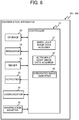
- the identification apparatus 100 includes a controller 10, a storage 20, an irradiator 31, an imager 32, an outputter 33, a communicator 34, and a manipulation inputter 35, as illustrated in FIG. 2 .
- the controller 10 includes a central processing unit (CPU) and the like, and implements the function of each unit (a white light image data acquirer 11, an ultraviolet light image data acquirer 12, a first white light image identifier 13, a first ultraviolet light image identifier 14, and a first final identifier 15) described later by executing a program stored in the storage 20.
- CPU central processing unit
- the storage 20 includes a read only memory (ROM), a random access memory (RAM), and the like. A program executed by the CPU of the controller 10, and needed data are stored in the storage 20.
- ROM read only memory
- RAM random access memory
- the irradiator 31 includes a device that emits white light as first irradiation light, such as a white light emitting diode (LED), and a device that emits ultraviolet light as second irradiation light, such as an ultraviolet light LED, and irradiates a site (such as the affected area of a patient), imaged by the imager 32, with white light or ultraviolet light.
- the controller 10 can instruct whether irradiation with white light or ultraviolet light is performed by the irradiator 31.
- the irradiator 31 may perform irradiation even with light including other light (for example, ultraviolet light) as the first irradiation light as long as the light includes white light.
- the irradiator 31 may perform irradiation with light including optional light (for example, infrared light) as the second irradiation light as long as the light includes light allowing an affected area to produce fluorescent reaction in the case of irradiating the affected area with the light.
- the light is not limited to ultraviolet light. In the present embodiment, ultraviolet light includes near-ultraviolet light.
- the imager 32 includes an imaging element such as a complementary metal oxide semiconductor (CMOS) image sensor, and captures an image into image data for training or (unknown) image data to be identified.
- CMOS complementary metal oxide semiconductor
- a color filter is disposed in front of the image sensor in order to perform color separation of visible light to be received into the three primary colors of light, and another filter may be further disposed in front of the image sensor in order to appropriately receive fluorescence light.
- the imager 32 may apply a digital filter to image data obtained by capturing of an image.
- the controller 10 acquires the image data obtained by the capturing by the imager 32, as image data including a set of 3-ch pixel values of RGB.
- the imager 32 may receive and image not only visible light but also light including optional light (for example, light including ultraviolet light or infrared light in addition to visible light (instead of visible light), or the like).
- optional light for example, light including ultraviolet light or infrared light in addition to visible light (instead of visible light), or the like.
- the kind of a filter may be changed (for example, a filter that extracts ultraviolet rays may be disposed) depending on received light.
- the controller 10 may acquire the image data by reading out the image data from the storage 20.
- the controller 10 may acquire image data from an external server or the like via the communicator 34.
- the identification apparatus 100 need not include the irradiator 31 or the imager 32.
- the outputter 33 is a device for outputting, for example, a result in which the controller 10 identifies an affected area captured in image data obtained by the capturing by the imager 32.
- the outputter 33 is a liquid crystal display or an organic electroluminescence (EL) display.
- the outputter 33 functions as a display.
- the identification apparatus 100 may include such a display (display) as the outputter 33, or may include the outputter 33 as an interface for connection of an external display instead of the display.
- the identification apparatus 100 displays an identification result or the like on the external display connected via the outputter 33 when including the outputter 33 as the interface.
- the identification apparatus 100 may include, as the outputter 33, a speaker or the like that provides as a sound output an identification result of the affected area or the like.
- the communicator 34 is a device (a network interface or the like) for transmitting and receiving data to and from another external apparatus (for example, a server in which the database of image data is stored, or the like).
- the controller 10 can acquire image data and the like via the communicator 34.
- the manipulation inputter 35 which is a device that accepts manipulated input into the identification apparatus 100 by a user, is, for example, a keyboard, a mouse, a touch panel, or the like.
- the identification apparatus 100 accepts an instruction or the like from a user via the manipulation inputter 35.
- the functions of the controller 10 will now be described.
- the controller 10 implements the functions of the white light image data acquirer 11, the ultraviolet light image data acquirer 12, the first white light image identifier 13, the first ultraviolet light image identifier 14, and the first final identifier 15.
- the white light image data acquirer 11 acquires white light image data obtained by receiving and imaging reflection light (first reception light) reflected from an affected area irradiated with white light (first irradiation light).
- the white light image data is image data including a set of 3-ch pixel values of RGB which are the color components of an RGB color space. According to each pixel, the white light image data includes R-value indicating the degree of the red of the pixel, G-value indicating the degree of the green of the pixel, and B-value indicating the degree of the blue of the pixel.
- the white light image data is also referred to as first image data.
- the white light image data acquirer 11 functions as first image data acquisition means.
- the ultraviolet light image data acquirer 12 acquires ultraviolet light image data obtained by receiving and imaging light (second reception light) including light generated by fluorescent reaction in an affected area irradiated with ultraviolet light (second irradiation light). Like the white light image data, the ultraviolet light image data is image data including a set of 3-ch pixel values of RGB, and includes R-value, G-value, and B-value according to each pixel. The ultraviolet light image data is also referred to as second image data. The ultraviolet light image data acquirer 12 functions as second image data acquisition means.
- Both the first white light image identifier 13 and the first ultraviolet light image identifier 14 are identifiers for an image, based on a convolutional neural network (CNN) which is a kind of a deep neural network (DNN).
- CNN convolutional neural network
- DNN deep neural network
- the controller 10 functions as the first white light image identifier 13 as well as the first ultraviolet light image identifier 14 by executing a program that implements an identifier based on the CNN
- the first white light image identifier 13 includes an input layer into which white light image data acquired by the white light image data acquirer 11 is input, an output layer, and an intermediate layer between the input layer and the output layer, and outputs, from the output layer, the result of identifying an affected area captured in the white light image data.
- the first white light image identifier 13 is also referred to as a first identifier.
- Training a machine learning model based on a training data set to which a correct answer label indicating whether an affected area captured in each image data is benign or malignant is assigned allows the first white light image identifier 13 to output, from the output layer, a probability that the affected area is malignant, when white light image data with an captured image of the affected area is input into the first white light image identifier 13 (the training is performed so that a probability that the affected area is malignant is output in the present embodiment although the training can also be performed so that a probability that the affected area is benign is output from the output layer).
- the controller 10 executes a first identification process by the first white light image identifier 13 functions as first identification means for identifying whether or not the affected area is malignant.
- the first ultraviolet light image identifier 14 includes an input layer into which ultraviolet light image data acquired by the ultraviolet light image data acquirer 12 is input, an output layer, and an intermediate layer between the input layer and the output layer, and outputs, from the output layer, the result of identifying an affected area captured in the ultraviolet light image data.
- the first ultraviolet light image identifier 14 is also referred to as a second identifier.
- Training a machine learning model based on a training data set to which a correct answer label indicating whether an affected area captured in each image data is benign or malignant is assigned allows the first ultraviolet light image identifier 14 to output, from the output layer, a probability that the affected area is malignant, when ultraviolet light image data with a captured image of the affected area is input into the first ultraviolet light image identifier 14 (the training is performed so that a probability that the affected area is malignant is output in the present embodiment although the training can also be performed so that a probability that the affected area is benign is output from the output layer).
- the controller 10 executes a second identification process by the first ultraviolet light image identifier 14 functions as second identification means for identifying whether or not the affected area is malignant.
- the first final identifier 15 obtains a final identification result using both an output (probability that the affected area captured in the white light image data is malignant) from the first white light image identifier 13 and an output (probability that the affected area captured in the ultraviolet light image data is malignant) from the first ultraviolet light image identifier 14.
- the first final identifier 15 simply arithmetically averages the output from the first white light image identifier 13 and the output from the first ultraviolet light image identifier 14 to obtain the final identification result, without limitation thereto.
- the first final identifier 15 may multiply, by an appropriate weight, each of the output from the first white light image identifier 13 and the output from the first ultraviolet light image identifier 14, and calculate the weighted mean of both the outputs, to obtain the final identification result.
- the first final identifier 15 functions as final identification means.
- the functional configuration of the identification apparatus 100 has been described above.
- An identifier training process will now be described with reference to FIG. 3 .
- the process is a process for allowing the first white light image identifier 13 and the first ultraviolet light image identifier 14 to learn training data based on white light image data or ultraviolet light image data by supervised learning.
- the process is executed in such learning. However, it is necessary to complete the execution before at least an identification process described below is executed.
- the controller 10 executes a training data generation process to generate a training data set necessary for supervised learning of the CNNs of the first white light image identifier 13 and the first ultraviolet light image identifier 14 (step S101).
- the training data generation process is a process of generating a white light training data set for training the first white light image identifier 13 and an ultraviolet light training data set for training the first ultraviolet light image identifier 14. The details of the process will be described later.
- Such a training data set is a training data aggregate including image data to which a correct answer label is assigned. The correct answer label indicates whether an affected area captured in the image data to which the correct answer label is assigned is benign or malignant.
- a CNN is intended to be trained so that input of image data with a captured image of an affected area results in output of the probability of the degree of the malignancy of the affected area, and therefore, "benign/malignant" as a correct answer label is assigned to the image data included in the training data set.
- the process of step S101 can be omitted.
- subsequent processes are carried out using the white light training data set and ultraviolet light training data set that have been already prepared.
- the CNN can be trained to output what disease might be included in an affected area at a higher probability, giving a probability of each disease, rather than to output a probability that the affected area is malignant.
- image data to which the disease name of the affected area for example, melanoma (malignant), basal cell cancer (malignant), nevus pigmentosus (benign), seborrheic keratosis (benign), or the like
- the disease name of the affected area for example, melanoma (malignant), basal cell cancer (malignant), nevus pigmentosus (benign), seborrheic keratosis (benign), or the like
- the disease name of the affected area for example, melanoma (malignant), basal cell cancer (malignant), nevus pigmentosus (benign), seborrheic keratosis (benign), or the like
- the controller 10 trains the CNN of the first white light image identifier 13 using the white light training data set generated in step S101 (step S102). Specifically, the controller 10 takes, from the white light training data set, one item of white light image data to which a correct answer label is assigned. A weighting factor in the CNN is updated by an error back propagation method so that a difference (error) becomes small between a value output from the output layer when the white light image data is input into the input layer of the CNN of the first white light image identifier 13 and the correct answer label assigned to the white light image data. The controller 10 repeats a process of taking another item of white light image data from the white light training data set and updating the weighting factor in the CNN by the error back propagation method again.
- the weighting factor in the CNN may be updated once according to each of all the items of the white light image data by, for example, the repetitions of which the number is the number of the items of the white light image data included in the white light training data set.
- step S103 the controller 10 trains the CNN of the first ultraviolet light image identifier 14 using the ultraviolet light training data set generated in step S101 (step S103), and ends the identifier training process.
- the specific process content of step S103 is similar to the process content of step S102 except that ultraviolet light image data is used instead of the white light image data.
- Step S102 and step S103 are also referred to as training steps.
- the identifier training process has been described above.
- the training data generation process executed in the step S101 described above will now be described with reference to FIG. 4 . It is necessarily that an affected area known to be benign or malignant has been prepared (or the affected area is diagnosed as benign or malignant whenever the affected area is photographed) when the training data generation process is executed.
- the training data generation process may continue to be executed for a long period such as several months or several years. For example, the following processes of steps S111 to S115 may be executed whenever a doctor examines a new affected area for several months.
- the imager 32 receives and images (performs visible-light photographing of) visible light reflected from an affected area in the state of irradiating the affected area with white light by the irradiator 31, and the white light image data acquirer 11 acquires white light image data (step Sill).
- the imager 32 captures an image of the affected area by receiving visible light (including reflected light and generated fluorescence light) from the affected area in a state in which the affected area photographed in step S111 is irradiated with ultraviolet light by the irradiator 31, which is visible-light photographing, and the ultraviolet light image data acquirer 12 acquires ultraviolet light image data (step S112).
- the visible-light photographing of step Sill and the visible-light photographing of step S112 it is desirable to perform high-speed consecutive shooting at a minimized interval; however, in Embodiment 1, the photographing is not limited to the high-speed consecutive shooting, but the photographing may be performed at an interval of 2 to 3 minutes, and the photographing may be performed at an interval of several days.
- the controller 10 acquires, from the manipulation inputter 35, the correct answer label of the affected area photographed in step S111 and step S112 (step S113).
- a doctor diagnoses whether a photographed affected area is benign or malignant, and the diagnosis result (benign/malignant) is input via the manipulation inputter 35 to allow the controller 10 to acquire the diagnosis result.
- time for which biopsy is performed (a lesion is removed) to obtain a pathological examination result or the diagnosis result is decided without biopsy by a consensus of several experts is often needed before the diagnosis result is obtained. Therefore, the execution of step S113 may require a time period of several days, several months, or several years.
- the acquired diagnosis result becomes a correct answer label assigned to the image data photographed in step S111 and step S112.
- the controller 10 assigns the correct answer label acquired in step S113 to the white light image data acquired in step S111 to generate white light training data, and adds the white light training data to the white light training data set stored in the storage 20 (step S114).
- a white light training data set consisting of one item of the white light training data generated in this case is stored in the storage 20.
- the controller 10 assigns the correct answer label acquired in step S113 to the ultraviolet light image data acquired in step S112 to generate ultraviolet light training data, and adds the ultraviolet light training data to the ultraviolet light training data set stored in the storage 20 (step S115).
- the ultraviolet light training data set has not yet been stored in the storage 20
- an ultraviolet light training data set consisting of one item of the ultraviolet light training data generated in this case is stored in the storage 20.
- the controller 10 determines whether or not to end the training data generation process (step S116).
- the end is determined, for example, in a case in which a doctor inputs the instruction of ending the training data generation process from the manipulation inputter 35, such as the case of completely finishing the input of the photographing and diagnosis results of the affected area prepared in advance by a doctor.
- step S116 No
- the process goes back to step Sill.
- step S116 the training data generation process is ended to go back to the process from step S102 of the identifier training process ( FIG. 3 ).
- the white light training data set and the ultraviolet light training data set are simultaneously generated in the training data generation process described above, it is also acceptable to generate only one training data set of both thereof. For example, when the white light training data set has already existed, it is also acceptable to skip the process for the white light image data, of the processes described above, and to generate only the ultraviolet light training data set.
- a required time period between photographing of the image and definitive diagnosis (between step S112 and step S113), or a required interval between medical examinations (interval of step S111 repeated in loop) may be several months or more. Accordingly, it is also acceptable to store, in a database in advance, image data and a correct answer label acquired in processes similar to the steps S111 to S113 described above prior to the training data generation process, and to read out the image data and the correct answer label from the database to thereby perform the training data generation process.
- Each CNN of the first white light image identifier 13 and the first ultraviolet light image identifier 14 is trained in the training data generation process and identifier training process described above.
- An identification process of identifying (inferring) the benignity and malignancy of an (unknown) affected area to be identified using the first white light image identifier 13 and the first ultraviolet light image identifier 14 in which training is performed in such a manner will now be described with reference to FIG. 5 .
- the irradiator 31 irradiates an affected area to be identified with white light
- the white light image data acquirer 11 acquires, as white light image data, the R-, G-, and B-values of an image obtained by capturing of an image of the affected area by the imager 32 by irradiating by the irradiator 31 the affected arear to be identified with the white light and receiving visible light reflected from the affected area irradiated with the white light (step S201).
- Step S201 is also referred to as a first image data acquisition step.
- the ultraviolet light image data acquirer 12 acquires, as ultraviolet light image data, the R-, G-, and B-values of an image obtained by capturing of an image of an affected area by the imager 32 by receiving visible light (including reflected light and generated fluorescence light) from the affected area irradiated with ultraviolet light in a state in which the affected area to be identified is irradiated with the ultraviolet light by the irradiator 31 (step S202).
- Step S202 is also referred to as a second image data acquisition step.
- the photographing is not limited to the high-speed consecutive shooting, but the photographing may be performed at an interval of 2 to 3 minutes, and the photographing may be performed at an interval of several days or several months.
- the controller 10 inputs, into the first white light image identifier 13, the white light image data acquired in step S201, and acquires an identification result obtained by the first white light image identifier 13 (the output value of the CNN of the first white light image identifier 13) (step S203).
- the controller 10 inputs, into the first ultraviolet light image identifier 14, the ultraviolet light image data acquired in step S202, and acquires an identification result obtained by the first ultraviolet light image identifier 14 (the output value of the CNN of the first ultraviolet light image identifier 14) (step S204).
- the first final identifier 15 computes the arithmetic mean of the output value of the CNN of the first white light image identifier 13, acquired in step S203, and the output value of the CNN of the first ultraviolet light image identifier 14, acquired in step S204, (sum of both values/2), and determines the computed arithmetic mean as an identification result which is final (final identification result) (step S205).
- Step S205 is also referred to as a final identification step.
- the controller 10 displays the final identification result on the outputter 33 (step S206), and ends the identification process.
- the controller 10 identifies the affected area according to the CNN which is a model in which machine learning is performed.
- the present embodiment is described using a CNN as an example of the learning model used in identification of an affected area.
- a support vector machine (SVM), logistic regression, random forest, Adaboost, Gradient boosting, a recurrent neural network (RNN), or the like may be used, or two or more thereof may be used in combination.
- an identification result based on usual white light image data and an identification result based on ultraviolet light image data can be integrated to obtain a final identification result.
- it may be difficult to make identification for example, between a keratotic plug and melanin.
- use of the ultraviolet light image data facilitates the identification between a keratotic plug and melanin.
- an affected area with many keratotic plugs is highly likely to be benign. Accordingly, use of the final identification result determined as described above can result in improvement in identification performance in comparison with conventional identification (based on only white light image data).
- the ultraviolet light image data acquirer 12 described above acquires, as ultraviolet light image data, the R-, G-, and B-values of the image obtained by capturing of the image of the affected area by the imager 32 by receiving visible light (including reflected light and generated fluorescence light) from the affected area irradiated with ultraviolet light in the state in which the affected area to be identified is irradiated with ultraviolet light by the irradiator 31.
- the ultraviolet light image data acquirer 12 may acquire, as ultraviolet light image data, the R- and G-values of an image obtained by imaging by the imager 32 as described above.
- the input layer of the CNN of the first ultraviolet light image identifier 14 is configured so that ultraviolet light image data including R-value and G-value (including no B-value) is input into the input layer.
- the controller 10 trains the first ultraviolet light image identifier 14 using an ultraviolet light image training data set generated using the ultraviolet light image data including R-value and G-value by machine learning.
- the first final identifier 15 can integrate the result of identifying the affected area using the white light image data including 3-ch RGB by the first white light image identifier 13 and the result of identifying the affected area using the ultraviolet light image data including 2-ch RG by the first ultraviolet light image identifier 14, to determine the final identification result.
- the ultraviolet light image data includes only 2-ch RG, and therefore, a data amount can be reduced in comparison with the case of using 3-ch RGB.
- use of the 2-ch RG of the ultraviolet light image data is considered to enable the existence or non-existence of a keratotic plug to determined, and therefore, in such a case, identification performance can also be improved in comparison with conventional identification (based on only white light image data).
- the white light training data set and the ultraviolet light training data set are independent of each other. Therefore, for example, for the white light training data set, use of published training data enables the process for the white light image data, of the training data generation processes described above, to be skipped to shorten time required for the training data generation processes. In addition, it is not necessary to introduce a facility for high-speed consecutive shooting because it is not necessary to perform high-speed consecutive shooting for white light image data and ultraviolet light image data even when an affected area is identified.
- Embodiment 1 white light image data and ultraviolet light image data are input into the separate identifiers, respectively, to identify the affected area. However, it is also conceivable that white light image data and ultraviolet light image data are collectively input into one identifier. Such Variation 1 will be described.
- the functional configuration of an identification apparatus 101 according to Variation 1 is a configuration in which the first white light image identifier 13, first ultraviolet light image identifier 14, and first final identifier 15 of the identification apparatus 100 according to Embodiment 1 are replaced with an integrated image identifier 16, as illustrated in FIG. 6 .
- the integrated image identifier 16 is also an identifier using, as input data, image data based on CNN which is a kind of DNN, like the first white light image identifier 13 and the first ultraviolet light image identifier 14.
- a controller 10 functions as the integrated image identifier 16 by executing a program that implements the identifier based on the CNN
- each of the first white light image identifier 13 and the first ultraviolet light image identifier 14 accepts one item of image data as input data
- the integrated image identifier 16 accepts, as input data, one item of integrated image data into which two items of image data are unified.
- the integrated image identifier 16 includes an input layer into which integrated image data including 6-ch RGB into which white light image data of 3-ch RGB acquired by a white light image data acquirer 11 and ultraviolet light image data of 3-ch RGB acquired by an ultraviolet light image data acquirer 12 are unified is input, an output layer, and an intermediate layer between the input layer and the output layer.
- the integrated image identifier 16 outputs, from the output layer, the result of identifying an affected area captured in the white light image data and the ultraviolet light image data included in the integrated image data (6-ch).
- the other configuration of the identification apparatus 101 is similar to the configuration of the identification apparatus 100, and therefore, the descriptions thereof are omitted.
- An integrated image learning process in which the integrated image identifier 16 is trained by supervised machine learning will now be described with reference to FIG. 7 . The process is executed when the integrated image identifier 16 is trained. It is necessary to complete the execution at least prior to execution of an integrated image identification process described below.
- the controller 10 executes an integrated training data generation process to generate an integrated training data set necessary for supervised machine learning of the CNN of the integrated image identifier 16 (step S301).
- the details of the integrated training data generation process will be described later.
- the integrated training data set is an aggregate of integrated image data to which correct answer labels are assigned.
- the integrated image data in Variation 1 is one item of image data including 6-ch RGB, into which white light image data of 3-ch RGB and ultraviolet light image data of 3-ch RGB, subjected to high-speed consecutive shooting, are unified.
- the controller 10 trains the CNN of the integrated image identifier 16 by machine learning using the integrated training data set generated in step S301 (step S302). Specifically, the controller 10 takes, from the integrated training data set, one item of integrated image data to which a correct answer label is assigned. A weighting factor in the CNN is updated by an error back propagation method so that a difference (error) becomes small between a value output from the output layer when the integrated image data is input into the input layer of the CNN of the integrated image identifier 16 and the correct answer label assigned to the integrated image data.
- the controller 10 repeats a process of taking another item of integrated image data from the integrated training data set and updating the weighting factor in the CNN is by the error back propagation method again. The number of such repetitions is optional. However, the weighting factor in the CNN may be updated once according to each of all the items of the integrated image data by, for example, the repetitions of which the number is the number of the items of the integrated image data included in the integrated training data set.
- step S301 When the CNN of the integrated image identifier 16 is trained in step S302, the integrated image learning process is ended.
- the integrated training data generation process executed in step S301 described above will now be described with reference to FIG. 8 .
- the integrated training data generation process may continue to be executed for a long period such as several months or several years. For example, the following processes of steps S311 to S314 may be executed whenever a doctor examines a new affected area for several months.
- each process of from steps S311 to step S313 of the integrated training data generation process is similar to each process of from step S111 to step S113 of the training data generation process ( FIG. 4 ) according to Embodiment 1, and therefore, the descriptions thereof are omitted.
- the visible light photographing of step S311 and the visible light photographing of step S312 are performed at a time interval of not more than consecutive shooting reference time by high-speed consecutive shooting. In other words, a time difference between the image capturing timing for the white light image data acquired in step S311 and the image capturing timing for the ultraviolet light image data acquired in step S312 is not more than the consecutive shooting reference time.
- the controller 10 assigns the correct answer label acquired in step S313 to one item of integrated image data (6-ch RGB) into which the white light image data (3-ch RGB) acquired in step S311 and the ultraviolet light image data (3-ch RGB) acquired in step S312 are integrated and unified to generate integrated training data, and adds the integrated training data to the integrated training data set stored in a storage 20 (step S314).
- integrated training data set has not yet been stored in the storage 20
- an integrated training data set consisting of one item of the integrated training data generated in this case is stored in the storage 20.
- step S315 determines whether or not to end the integrated training data generation process.
- the end is determined, for example, in a case in which a doctor inputs the instruction of ending the integrated training data generation process from the manipulation inputter 35, such as the case of completely finishing the input of the photographing and diagnosis results of the affected area prepared in advance by a doctor.
- step S315; No the process goes back to step S311.
- step S315 When the end is determined (step S315; Yes), the training data generation process is ended to go back to the process from step S302 of the integrated image learning process ( FIG. 7 ).
- the CNN of the integrated image identifier 16 is trained in the integrated training data generation process and the integrated image learning process described above.
- An integrated image identification process of identifying (inferring) the benignity and malignancy of the (unknown) affected area to be identified using the integrated image identifier 16 in which training is performed in such a manner will now be described with reference to FIG. 9 .
- step S401 and step S402 of the integrated image identification process is similar to each process of step S201 and step S202 of the identification process ( FIG. 5 ) according to Embodiment 1, and therefore, the descriptions thereof are omitted.
- the visible light photographing of step S401 and the visible light photographing of step S402 are performed at a time interval of not more than consecutive shooting reference time by high-speed consecutive shooting. In other words, a time difference between the image capturing timing for the white light image data acquired in step S401 and the image capturing timing for the ultraviolet light image data acquired in step S402 is not more than the consecutive shooting reference time.
- the controller 10 unifies the white light image data (3-ch RGB) acquired in step S401 and ultraviolet light image data (3-ch RGB) acquired in step S402 to generate one item of integrated image data (6-ch RGB) (step S403).
- the controller 10 inputs the generated integrated image data into the integrated image identifier 16, and acquires an identification result based on the integrated image identifier 16 (step S404).
- the controller 10 displays the identification result based on the integrated image identifier 16 on an outputter 33 (step S405), and ends the integrated image identification process.
- the identification can be performed using the integrated image data including both the usual information of white light image data and the information of ultraviolet light image data in which a keratotic plug can be easily determined, and therefore, identification performance can be improved in comparison with conventional identification (based on only white light image data).
- the positional deviation between the images of the white light image data and the ultraviolet light image data can be minimized by allowing a time difference between the image capturing timing for the white light image data and the image capturing timing for the ultraviolet light image data to be not more than consecutive shooting reference time.
- An identifier used in the identification is only the one integrated image identifier 16, and therefore, the identification process can be simplified.
- the functional configuration of an identification apparatus 102 according to Variation 2 is a configuration in which the first white light image identifier 13, first ultraviolet light image identifier 14, and first final identifier 15 of the identification apparatus 100 according to Embodiment 1 are replaced with an integrated image identifier 16, as illustrated in FIG. 6 .
- the configuration is similar to the configuration of the identification apparatus 101 according to Variation 1. However, the configurations differ from each other in a point in which the integrated image data accepted as input image data by the integrated image identifier 16 of the identification apparatus 101 is image data corresponding to 6-ch RGB whereas the integrated image data accepted as input image data by the integrated image identifier 16 of the identification apparatus 102 is image data corresponding to 5-ch in which the ch of blue (B) is removed from ultraviolet light image data.
- the integrated image data in Variation 2 is one item of image data including 5-ch, into which the 3-ch RGB of the white light image data and the 2-ch RG of the ultraviolet light image data, obtained by high-speed consecutive shooting, are unified.
- the integrated image identifier 16 includes an input layer into which the integrated image data including 5-ch, into which the 3-ch RGB of the white light image data acquired by a white light image data acquirer 11 and the 2-ch RG of ultraviolet light image data acquired by an ultraviolet light image data acquirer 12 are unified, is input, an output layer, and an intermediate layer between the input layer and the output layer, and outputs, from the output layer, the result of identifying an affected area captured in the white light image data and the ultraviolet light image data included in the integrated image data (5-ch).
- the other configuration of the identification apparatus 102 is similar to the configuration of the identification apparatus 101, and therefore, the descriptions thereof are omitted.
- An integrated image learning process of training the integrated image identifier 16 and an integrated training data generation process are also similar to the integrated image learning process ( FIG. 7 ) and integrated training data generation process ( FIG. 8 ) according to Variation 1 except that the integrated image data is data corresponding to 5-ch rather than data corresponding to 6-ch, and the descriptions thereof are omitted.
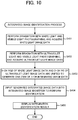
- An integrated image identification process of identifying (inferring) the benignity and malignancy of an (unknown) affected area to be identified in Variation 2 will be described with reference to FIG. 10 .
- step S451 to step S452 of the integrated image identification process according to Variation 2 are similar to the processes of from step S401 to step S402 of the integrated image identification process ( FIG. 9 ) according to Variation 1, and therefore, the descriptions thereof are omitted.
- the ultraviolet light image data acquirer 12 acquires ultraviolet light image data including R-value and G-value (including no B-value) in step S452.
- the controller 10 unifies white light image data (3-ch RGB) acquired in step S451 and ultraviolet light image data (2-ch RG) acquired in step S452 into one item of 5-ch integrated image data (step S453).
- the controller 10 inputs the generated integrated image data into the integrated image identifier 16, and acquires an identification result based on the integrated image identifier 16 (step S454).
- the controller 10 displays the identification result based on the integrated image identifier 16 on an outputter 33 (step S455), and ends the integrated image identification process.
- the identification can be performed using the integrated image data including both the usual information of white light image data and the information of ultraviolet light image data in which a keratotic plug can be easily determined, and therefore, identification performance can be improved in comparison with conventional identification (based on only white light image data).
- the ultraviolet light image data is the 2-ch data of only R-value and G-value, and therefore, the load of the process can be reduced, and a data amount required for training can also be reduced, in comparison with the integrated image process according to Variation 1.
- the functional configuration of an identification apparatus 103 according to Variation 3 is a configuration in which a second white light image identifier 17, a second ultraviolet light image identifier 18, and a second final identifier 19 are added to the identification apparatus 100 according to Embodiment 1, as illustrated in FIG. 11 .
- the second white light image identifier 17 is an identifier that identifies an affected area captured in white light image data.
- the first white light image identifier 13 according to Variation 3 is the identifier in which the affected area captured in the item of image data including the keratotic plug (image data with keratotic plug) among items of image data is targeted for identification.
- the second white light image identifier 17 is an identifier targeted for identification of an affected area captured in an item of image data in which no keratotic plug can be confirmed (image data in which it is impossible to confirm the existence of a keratotic plug because no keratotic plug exists so as to make fluorescence, although some keratotic plugs may exist; hereinafter, the image data is referred to as "image data without keratotic plug" for convenience although it cannot be said that any keratotic plug is completely absent) among the items of the image data.
- the second ultraviolet light image identifier 18 is an identifier that identifies an affected area captured in ultraviolet light image data.
- the first ultraviolet light image identifier 14 according to Variation 3 is the identifier targeted for identification of the affected area captured in the item of image data with the keratotic plug (also referred to as "second image data with keratotic plug") among items of ultraviolet light image data
- the second ultraviolet light image identifier 18 is an identifier targeted for identification of an affected area captured in an item of image data without a keratotic plug (also referred to as "second image data without keratotic plug") among items of ultraviolet light image data.
- the second ultraviolet light image identifier 18 can identify the affected area using fluorescence other than fluorescence based on a keratotic plug.
- a first final identifier 15 uses both of an output (the result of identifying the affected area captured in white light image data including the keratotic plug) from the first white light image identifier 13 and the output (the result of identifying the affected area captured in ultraviolet light image data including the keratotic plug) from the first ultraviolet light image identifier 14 to perform an adoption identifier determination/training process described below, and uses an adoption identifier allowed to perform determination and training by the process to obtain a final identification result.
- the second final identifier 19 uses both of an output (the result of identifying the affected area captured in white light image data including no keratotic plug) from the second white light image identifier 17 and an output (the result of identifying the affected area captured in ultraviolet light image data including no keratotic plug) from the second ultraviolet light image identifier 18 to perform the adoption identifier determination/training process described below, and uses the adoption identifier allowed to perform determination and training by the process to obtain the final identification result.
- the other configuration of the identification apparatus 103 is similar to the configuration of the identification apparatus 100, and the descriptions thereof are omitted.
- An image learning process for the existence or non-existence of a keratotic plug which is a learning process in the identification apparatus 103 will now be described with reference to FIG. 12 .
- the process is executed when the first white light image identifier 13, the first ultraviolet light image identifier 14, the second white light image identifier 17, and the second ultraviolet light image identifier 18 are trained by supervised machine learning. It is necessary to complete the execution at least prior to execution of an identification process for use of the existence or non-existence of a keratotic plug described below.
- a controller 10 executes an integrated training data generation process to generate an integrated training data set necessary for supervised machine learning of the CNN of the aliquot identifier (step S501).
- the integrated image data included in the integrated training data set in Variation 3 is one item of image data including 6-ch RGB, into which the 3-ch RGB of white light image data and the 3-ch RGB of ultraviolet light image data, subjected to high-speed consecutive shooting, are unified.
- the integrated training data generation process executed in step S501 is similar to the integrated training data generation process ( FIG. 8 ) in Variation 1.
- the controller 10 generates an integrated training data set by generating plural items of integrated training data obtained by assigning a correct answer label to integrated image data.
- the controller 10 assigns a label indicating the existence or non-existence of a keratotic plug to the integrated training data (step S502).
- each pixel value (each of R-value, G-value, and B-value) included in each item of image data is 0 or more and 255 or less, and a keratotic plug determination threshold value is 128, a label of "existence of keratotic plug" is assigned to integrated training data including ultraviolet light image data when the maximum value of R-value included is 128 or more, or the maximum value of G-value is 128 or more in the ultraviolet light image data. Assuming that both the maximum values of R- and G-values included in ultraviolet light image data are less than 128, a label of "non-existence of keratotic plug" is assigned to integrated image data including the ultraviolet light image data.
- a label of "non-existence of keratotic plug” does not only indicate that a keratotic plug is completely absent but indicates that it is impossible to confirm any keratotic plug on the basis of the pixel values of RGB, and a label of "non-existence of keratotic plug” is assigned when the maximum values of R- and
- G-values are less than the keratotic plug determination threshold value (when it is impossible to confirm fluorescence) even in the existence of some keratotic plugs.
- step S502 when at least one of R-value or G-value that is not less than the keratotic plug determination threshold value is present in targeted ultraviolet light image data, a label of "existence of keratotic plug" is assigned to integrated training data including the ultraviolet light image data.
- the keratotic plug determination threshold value and the method of assigning a label in such a case are exemplary.
- the keratotic plug determination threshold value is divided into the threshold values of R- and G-values, and a label of "existence of keratotic plug" may be assigned to integrated training data including ultraviolet light image data when the maximum value of R-value included in the ultraviolet light image data is not less than the keratotic plug determination R threshold value (for example, 80) or the maximum value of G-value is not less than the keratotic plug determination G threshold value (for example, 160).
- the keratotic plug determination threshold value can be optionally set.
- a label indicating the existence or non-existence of a keratotic plug may be assigned based on the result of diagnosis performed by a doctor regardless of the keratotic plug determination threshold value in the keratotic plug existence/non-existence image learning process.
- the controller 10 may determine the existence or non-existence of a keratotic plug by an optional method, which is not limited to the method described above.
- the controller 10 may assign a label indicating the existence or non-existence of the keratotic plug to each item of integrated training data on the basis of the existence or non-existence of the keratotic plug, determined by the optional method.
- Step S502 is also referred to as a keratotic plug existence/non-existence determining step.
- the controller 10 performs an adoption identifier determination/training process described below using integrated training data to which a label of "existence of keratotic plug" is assigned in step S502 (training data for existence of keratotic plug) among plural items of integrated training data included in the integrated training data set generated in step S501, and performs determination and training of an identifier (or a combination of identifiers) adopted as an identifier for the existence of a keratotic plug by the first final identifier 15 (step S503).
- the controller 10 executes a keratotic-plug-existence identification process by the identifier (or the combination of identifiers) determined in step S503 functions as keratotic-plug-existence identification means.
- the controller 10 performs the adoption identifier determination/training process described below using integrated training data to which a label of "non-existence of keratotic plug" is assigned in step S502 (training data for non-existence of keratotic plug) among the plural items of integrated training data included in the integrated training data set generated in step S501, performs determination and training of an identifier (or a combination of identifiers) adopted as an identifier for the non-existence of a keratotic plug by the second final identifier 19 (step S504), and ends the keratotic plug existence/non-existence image learning process.
- the controller 10 executes a keratotic-plug-non-existence identification process by the identifier (or the combination of identifiers) determined in step S504 functions as keratotic-plug-non-existence identification means.
- identifiers targeted for the adoption identifier determination/training process are the first white light image identifier 13 and the first ultraviolet light image identifier 14 in the case of using integrated training data to which the label of "existence of keratotic plug" is assigned, or the second white light image identifier 17 and the second ultraviolet light image identifier 18 in the case of using integrated training data to which the label of "non-existence of keratotic plug" is assigned.
- the controller 10 subjects "identifier A" for white light image data (the first white light image identifier 13 or the second white light image identifier 17) to cross validation described later, and acquires a first evaluation value which is the evaluation value of the identifier A (step S551).
- the evaluation value is a value (for example, correct answer rate) that evaluates the correctness of the result of identification performed by the identifier.
- An evaluation data set used in determination of the evaluation value is an evaluation data aggregate including image data and correct answer labels therefor, and the data structure of the evaluation data set is similar to that of the training data set.
- the controller 10 also subjects "identifier B" for ultraviolet light image data (the first ultraviolet light image identifier 14 or the second ultraviolet light image identifier 18) to cross validation, and acquires a second evaluation value which is the evaluation value of the identifier B (step S552).
- the controller 10 also subjects "identifier A + identifier B (arithmetic mean of output value from identifier A and output value from identifier B)" to cross validation, and acquires a third evaluation value which is the evaluation value of "identifier A + identifier B" (a combination of the identifier A and the identifier B) (step S553).
- the process of from step S551 to step S553 is also referred to as "validation step".
- Step S554 is also referred to as a determination step.
- an adoption identifier adopted as an identifier for the existence of a keratotic plug by the first final identifier 15 is determined in the case of using integrated training data to which the label of "existence of keratotic plug" is assigned.
- An adoption identifier adopted as an identifier for the non-existence of a keratotic plug by the second final identifier 19 is determined in the case of using integrated training data to which the label of "non-existence of keratotic plug" is assigned.
- the adoption identifiers are trained using all the items of integrated training data (to which corresponding labels for the existence or non-existence of a keratotic plug are assigned) (step S555), and the adoption identifier determination/training process is ended.
- n-fold cross validation 1/n of the whole training data set is used as an evaluation data set, and (n-1)/n as the remainder is used as a transitory training data set in the case of validation with the evaluation data set (in the case of determination of the evaluation value).
- a method of acquiring an evaluation value from the whole training data set will now be described by taking the identifier A as an example.
- an identification result output from identifier
- the evaluation value is set so that the evaluation value is increased with decreasing a difference between a numeral value (correct answer value) into which a correct answer label is converted and an output (probability) from an identifier.
- the identifier A is trained using the initial 2/3 (training data) of training data.
- An output from the identifier A in the case of inputting the remaining 1/3 (evaluation data) of the training data into the trained identifier A is compared with the numeral value (correct answer value) into which the correct answer label (assigned to each item of evaluation data) is converted.
- the evaluation value 1 is set so that the evaluation value 1 becomes a value that is increased with decreasing a difference between the output from the identifier A and the correct answer value.
- an output from the identifier A is the probability (0.0 or more and 1.0 or less) of the malignancy of an affected area. Therefore, when correct answer labels are converted into numeral correct answer values, correct answer values, for example, in cases in which correct answer labels are "benign” and “malignant” can be defined as 0.0 and 1.0, respectively. Accordingly, "difference between output from identifier A and correct answer value" is (output from identifier A - 0.0) in a case in which the correct answer label is "benign” or (1.0 - output from identifier A) in a case in which the correct answer label is "malignant".
- a value (total sum of differences) obtained by addition of "differences between outputs from identifier A and correct answer values" in the case of inputting all the respective items of evaluation data into the identifier A is determined, and the inverse number of the value (total sum of differences) is regarded as the evaluation value 1.
- the identifier A is trained using, as training data, the initial 1/3 and end 1/3 of the training data included in the training data set, and an evaluation value obtained by evaluating the identifier A trained using the middle 1/3 of the training data as evaluation data is regarded as an evaluation value 2.
- the identifier A is trained using, as training data, the end 2/3 of the training data included in the training data set, and an evaluation value obtained by evaluating the identifier A trained using the initial 1/3 of the training data as evaluation data is regarded as an evaluation value 3.
- Methods of computing the evaluation value 2 and the evaluation value 3 are similar to the above-described method of computing the evaluation value 1.
- the method of computing the evaluation value (first evaluation value) by taking the identifier A as an example has been described above.
- the evaluation value (second evaluation value) of the identifier B can also be similarly determined.
- the evaluation value (third evaluation value) of the combination (identifier A + identifier B) of the identifier A and the identifier B can be determined as described below.
- each of the identifier A and the identifier B is trained using the initial 2/3 of training data as training data.
- the average value of the output from the identifier A and the output from the identifier B in the case of inputting the remaining 1/3 (evaluation data) of the training data into each of the trained identifier A and the trained identifier B is compared with the numeral value (correct answer value) into which the correct answer label (assigned to each item of evaluation data) is converted.
- the evaluation value 1 is set so that the evaluation value 1 is a value that is increased with decreasing the difference between the correct answer value and the average value of the output from the identifier A and the output from the identifier B.
- the evaluation value 2 and the evaluation value 3 are determined in a similar manner, the total (or the average value or the like is also acceptable) of the evaluation value 1, the evaluation value 2, and the evaluation value 3 is regarded as the evaluation value (third evaluation value) of the combination (identifier A + identifier B) of the identifier A and the identifier B, obtained from the whole training data set used in such a case.
- step S551 to S553 of the adoption identifier determination/training process described above the evaluation value obtained from the whole training data set is acquired for each of three patterns of the identifier A, the identifier B, and identifier A + identifier B (the arithmetic mean of the output value from the identifier A and the output value from the identifier B) (identifier or combination of identifiers) in such a manner as described above.
- step S554 the pattern with the highest evaluation value (identifier or combination of identifiers) is determined as an adoption identifier (that is, the identifier for the existence of a keratotic plug or the identifier for the non-existence of a keratotic plug).
- step S555 the determined adoption identifier is trained using all the items of integrated training data included in the integrated training data set.
- the training data set in FIG. 14 is a training data set including all the items of integrated training data to which the label of "existence of keratotic plug" is assigned in a case in which the adoption identifier determination/training process ( FIG. 13 ) is called from step S503 of the keratotic plug existence/non-existence image learning process ( FIG. 12 ).
- the training data set in FIG. 14 is a training data set including all the items of integrated training data to which the label of "non-existence of keratotic plug” is assigned in a case in which the adoption identifier determination/training process ( FIG. 13 ) is called from step S504 of the keratotic plug existence/non-existence image learning process ( FIG. 12 ).
- the training data set includes all the items of integrated training data to which the label of "existence of keratotic plug" is assigned, and the pattern of the identifier with the highest evaluation value is "identifier A + identifier B (arithmetic mean of output value from identifier A and output value from identifier B)"
- the first final identifier 15 adopts "arithmetic mean of output value from first white light image identifier 13 and output value from first ultraviolet light image identifier 14" as an output from an identifier for the existence of a keratotic plug
- the controller 10 trains each of the first white light image identifier 13 and the first ultraviolet light image identifier 14 using all the items of integrated image data (image data including 6-ch RGB) to which the label of "existence of keratotic plug" included in the integrated training data set is assigned.
- the training data set includes all the items of integrated training data to which the label of "non-existence of keratotic plug" is assigned, and the pattern of the identifier with the highest evaluation value is "identifier A"
- the controller 10 trains the second white light image identifier 17 using all the items of integrated training data to which the label of "non-existence of keratotic plug" is assigned, included in the integrated training data set.
- the training data set includes two kinds of data to which the label of "existence of keratotic plug” is assigned (integrated training data for existence of keratotic plug) and data to which the label of "non-existence of keratotic plug” is assigned (integrated training data for non-existence of keratotic plug), and the pattern of the identifier with the highest evaluation value, of the three patterns of the identifiers ("identifier A", "identifier B,” and "identifier A + identifier B”), is trained for each of the integrated training data for the existence of a keratotic plug and the integrated training data for the non-existence of a keratotic plug.
- the output value in a case in which the pattern of the identifier is "identifier A + identifier B" is set at "arithmetic mean of output value from identifier A and output value from identifier B".
- the output value need not be limited to the arithmetic mean.
- the controller 10 also adds, for example, plural patterns of weighted means in which various weights are used to candidates for cross validation, performs cross validation of all the patterns, and determines the identifier of the pattern with the highest evaluation value (or a combination of identifiers with various weighted means) as an adopted identifier. It is not necessary to limit candidate identifiers per se to two of the identifier A and the identifier B.
- identifier A or the identifier B for example, another identifier such as an identifier that inputs an image subjected to pretreatment of cropping (cutting) the periphery of the lesion region of an affected area to normalize the size thereof, to thereby identify the affected area, or an identifier that inputs an image subjected to pretreatment of subjecting an image obtained by photographing an affected area to edge enhancement, to thereby identify the affected area may be added to candidate identifiers to perform cross validation.
- the identifier with the highest evaluation value obtained by cross validation may be determined as the adoption identifier adopted as the identifier that identifies the affected area.
- the CNNs of the first white light image identifier 13, the first ultraviolet light image identifier 14, the second white light image identifier 17, and the second ultraviolet light image identifier 18 are trained by the adoption identifier determination/training process and the keratotic plug existence/non-existence image learning process, described above.
- the keratotic plug existence/non-existence image learning process it is possible to divide training data depending on the existence or non-existence of a keratotic plug and to train each identifier. Therefore, the identifier for the existence of a keratotic plug can be trained only with image data with a keratotic plug, and the identifier for the non-existence of a keratotic plug can be trained only with image data without a keratotic plug.
- identifiers (or a combination of identifiers) considered to have the highest identification performance can be determined as adoption identifiers (first final identifier 15 and second final identifier 19) by performing cross validation.
- step S601 and step S602 are similar to the respective processes of step S401 and step S402 of the identification process ( FIG. 9 ) according to Variation 1, and therefore, the descriptions thereof are omitted.
- the visible light photographing of step S601 and the visible light photographing of step S602 need not be performed by high-speed consecutive shooting.
- the controller 10 determines whether or not the maximum values of the R- and G-values included in ultraviolet light image data acquired in step S602 are a keratotic plug determination threshold value or more (step S603).
- Step S603 is also referred to as a keratotic plug existence/non-existence determining step.
- the controller 10 functions as keratotic plug existence/non-existence determining means in step S603.
- the first final identifier 15 identifies the affected area by the identifier for the existence of a keratotic plug, determined in the keratotic plug existence/non-existence image learning process described above (step S604).
- the first final identifier 15 obtains a final identification result by the arithmetic mean of the output value from the first white light image identifier 13, obtained by inputting the white light image data that acquired in step S601 into the first white light image identifier 13, and the output value from the first ultraviolet light image identifier 14, obtained by inputting the ultraviolet light image data acquired in step S602 into the first ultraviolet light image identifier 14.
- the second final identifier 19 identifies the affected area by the identifier for the non-existence of a keratotic plug, determined in the keratotic plug existence/non-existence image learning process (step S605). For example, when the identifier for the non-existence of a keratotic plug is "identifier A", the second final identifier 19 obtains a final identification result by the output value from the second white light image identifier 17, obtained by inputting the white light image data acquired in step S601 into the second white light image identifier 17.
- the controller 10 displays, on an outputter 33, the final identification result based on the first final identifier 15 or the second final identifier 19 (step S606), and ends the identification process for use of the existence or non-existence of a keratotic plug.
- the method of determining the existence or non-existence of a keratotic plug in step S603 is exemplary.
- the keratotic plug determination threshold value divided into a keratotic plug determination R threshold value (for example, 80) and a keratotic plug determination G threshold value (for example, 160) may be set, or the controller 10 may determine the existence or non-existence of a keratotic plug by an optional method which is not limited to the method described above.
- training data is classified into training data for the existence of a keratotic plug and training data for the non-existence of a keratotic plug, and the dedicated identifiers (the identifier for the existence of a keratotic plug and the identifier for the non-existence of a keratotic plug) are trained using the items of the classified training data, respectively.
- a method of classifying the training data is not limited to the classification based on the existence or non-existence of a keratotic plug.
- training data is classified into training data for the face and the scalp, and training data for the whole body, and dedicated identifiers (an identifier for the face and the scalp, and an identifier for the whole body) are trained using the items of the classified training data, respectively.
- the label for the existence or non-existence of a keratotic plug is assigned to each item of the integrated training data.
- training data is classified into training data for the face and the scalp (training data in which the site of an affected area is the face or the scalp) and training data for the whole body (training data without depending on the site of an affected area) by assigning a site label (for example, "scalp" "face", or the like) indicating the site of an affected area in the body, captured in an image, to each item of integrated training data.
- the identifier for the face and the scalp, and the identifier for the whole body are trained by a process similar to the keratotic plug existence/non-existence image learning process ( FIG. 12 ) (however, training data with a site label of "scalp” or “face” is used instead of training data of "existence of keratotic plug", and all items of training data (that are not subjected to site separation) are used instead of training data of "non-existence of keratotic plug”; hereinafter, the process is referred to as "training process with use of site”).
- a keratotic plug is more likely to exist particularly in the face and the scalp in the sites of the body (a keratotic plug hardly exists in the other sites of the body than the face and the scalp). Therefore, when a keratotic plug exists in an image obtained by photographing an affected area, the affected area is more likely to be an affected area existing in the face or the scalp. Accordingly, in the Variation of Variation 3, an affected area can be identified by a process similar to the identification process for use of the existence or non-existence of a keratotic plug ( FIG.
- identification process with use of site is performed in the identifier for the face and the scalp in step S604, and identification is performed in the identifier for the whole body in step S605; hereinafter, the process is referred to as "identification process with use of site").
- an identifier dedicated to each site can be trained on the basis of the site label regardless of the existence or non-existence of a keratotic plug in the training process using a site as described above, and therefore, the training data of the face and the scalp in the case of detecting no keratotic plug can also be used for the training of the identifier for the face and the scalp.
- identification performance can be further improved by using the identifier for the face and the scalp, dedicated to use in the face and the scalp.
- execution of a program that implements an identifier based on CNN by the controller 10 allows the controller 10 to also function as the first white light image identifier 13, the first ultraviolet light image identifier 14, the integrated image identifier 16, the second white light image identifier 17, or the second ultraviolet light image identifier 18, without limitation thereto.
- the identification apparatuses 100, 101, 102, and 103 may include a device (for example, graphics processing unit (GPU), dedicated integrated circuit (IC), or the like) different from the controller 10, and the function of the first white light image identifier 13, the first ultraviolet light image identifier 14, the integrated image identifier 16, the second white light image identifier 17, or the second ultraviolet light image identifier 18 may be implemented by the device.
- a device for example, graphics processing unit (GPU), dedicated integrated circuit (IC), or the like
- Variation 3 is combined with Variation 1 or Variation 2, and identification is performed using the integrated image identifier 16 in which one item of 6-ch integrated image data into which the 3-ch RGB of white light image data and the 3-ch RGB of ultraviolet light image data are unified, or one item of 5-ch Integrated image data into which the 3-ch RGB of white light image data and the 2-ch RG of ultraviolet light image data are unified is used as input data, instead of or in addition to "identifier A + identifier B (arithmetic mean of output value from identifier A and output value from identifier B)".
- each of a first integrated image identifier for identifying an affected area captured in image data with a keratotic plug and a second integrated image identifier for identifying an affected area captured in image data without a keratotic plug is also prepared in the integrated image identifier 16.
- the evaluation value of the first integrated image identifier is determined.
- the evaluation value of the second integrated image identifier is determined.
- the adoption identifier determination/training process ( FIG. 13 ) of Variation 3 is performed after the identifier training process ( FIG. 3 ), and the result of identification with the pattern of the identifier with the highest evaluation value is regarded as an identification result in step S205 of the identification process ( FIG. 5 ).
- RGB color space as a color space expressing the colors of image data, and using R-value, G-value, and B-value as color components.
- the color space is not limited to the RGB color space.
- a YUV color space or a Lab color space may be used.
- the irradiator 31 emits ultraviolet light as the second irradiation light.
- the ultraviolet light is exemplary.
- the second irradiation light may be optional light as long as the light allows a keratotic plug and the like to show fluorescent reaction.
- the irradiator 31 may perform irradiation with the light (for example, light having a wavelength of 410 nm to 470 nm, preferably 440 nm or less), closer to ultraviolet light, of visible light, as the second irradiation light.
- Each function of the identification apparatuses 100, 101, 102, and 103 can also be implemented by a computer such as a usual personal computer (PC). Specifically, in the embodiment described above, it has been described that a program for the identification process performed by the identification apparatus 100, 101, 102, or 103, or the like is stored in the ROM of the storage 20 in advance.
- PC personal computer
- a computer that can implement each function described above by distributing a non-transitory computer-readable recording medium, such as a flexible disk, a compact disc read only memory (CD-ROM), a digital versatile disc (DVD), a magneto-optical disc (MO), a memory card, or a universal serial bus (USB) memory, in which the program is stored, and by allowing the computer to read and install the program.
- a non-transitory computer-readable recording medium such as a flexible disk, a compact disc read only memory (CD-ROM), a digital versatile disc (DVD), a magneto-optical disc (MO), a memory card, or a universal serial bus (USB) memory, in which the program is stored, and by allowing the computer to read and install the program.
Landscapes
- Engineering & Computer Science (AREA)
- Health & Medical Sciences (AREA)
- Theoretical Computer Science (AREA)
- Physics & Mathematics (AREA)
- Life Sciences & Earth Sciences (AREA)
- General Physics & Mathematics (AREA)
- General Health & Medical Sciences (AREA)
- Computer Vision & Pattern Recognition (AREA)
- Medical Informatics (AREA)
- Software Systems (AREA)
- Evolutionary Computation (AREA)
- Artificial Intelligence (AREA)
- Computing Systems (AREA)
- Molecular Biology (AREA)
- Biomedical Technology (AREA)
- Biophysics (AREA)
- Data Mining & Analysis (AREA)
- General Engineering & Computer Science (AREA)
- Pathology (AREA)
- Heart & Thoracic Surgery (AREA)
- Surgery (AREA)
- Animal Behavior & Ethology (AREA)
- Public Health (AREA)
- Veterinary Medicine (AREA)
- Mathematical Physics (AREA)
- Multimedia (AREA)
- Databases & Information Systems (AREA)
- Quality & Reliability (AREA)
- Radiology & Medical Imaging (AREA)
- Nuclear Medicine, Radiotherapy & Molecular Imaging (AREA)
- Computational Linguistics (AREA)
- Oral & Maxillofacial Surgery (AREA)
- Spectroscopy & Molecular Physics (AREA)
- Dermatology (AREA)
- Dentistry (AREA)
- Bioinformatics & Cheminformatics (AREA)
- Bioinformatics & Computational Biology (AREA)
- Evolutionary Biology (AREA)
- Image Analysis (AREA)
- Measuring And Recording Apparatus For Diagnosis (AREA)
Abstract
Description
- The present disclosure relates to an identification apparatus, an identifier training method, an identification method, and a program.
- For example, a diagnostic apparatus disclosed in Unexamined Japanese Patent Application Kokai Publication No.
2017-45341 - In such a conventional ensemble identifier as disclosure in Unexamined Japanese Patent Application Publication No.
2017-45341 - The present disclosure has been accomplished to solve the problems described above. An objective of the present disclosure is to provide an identification apparatus, an identifier training method, an identification method, and a program that enable further improvement in identification precision to be achieved in comparison with conventional identification apparatuses, identifier learning methods, identification methods, and programs.
- To achieve the above objective, according to an aspect of the present disclosure, an identification apparatus includes first image data acquisition means and second image data acquisition means, and final identification means. The first image data acquisition means acquires first image data obtained by capturing of an image of an affected area included in a skin or a mucosa by receiving first reception light. The first reception light is reflection light reflected from the affected area irradiated with first irradiation light including white light. The second image data acquisition means acquires second image data obtained by capturing of an image of the affected area by receiving second reception light. The second reception light is light including light generated by fluorescent reaction in the affected area irradiated with second irradiation light. The second irradiation light includes light that allows the affected area to show fluorescent reaction when the affected area is irradiated with the light. The final identification means identifies the affected area based on the first image data and the second image data.
- In accordance with the present disclosure, further improvement in identification precision can be achieved in comparison with conventional identification precision.
- A more complete understanding of this application can be obtained when the following detailed description is considered in conjunction with the following drawings, in which:
-
FIG. 1 is a diagram explaining the processing outline of an identification apparatus according toEmbodiment 1; -
FIG. 2 is a diagram illustrating the functional configuration of an identification apparatus according toEmbodiment 1; -
FIG. 3 is a flow chart of an identifier training process according toEmbodiment 1; -
FIG. 4 is a flow chart of a training data generation process according toEmbodiment 1; -
FIG. 5 is a flow chart of an identification process according toEmbodiment 1; -
FIG. 6 is a diagram illustrating the functional configuration of an identification apparatus according toVariation 1; -
FIG. 7 is a flow chart of an integrated image learning process according toVariation 1; -
FIG. 8 is a flow chart of an integrated training data generation process according toVariation 1; -
FIG. 9 is a flow chart of an integrated image identification process according toVariation 1; -
FIG. 10 is a flow chart of an integrated image identification process according toVariation 2; -
FIG. 11 is a diagram illustrating the functional configuration of an identification apparatus according toVariation 3; -
FIG. 12 is a flow chart of an image learning process for the existence or non-existence of a keratotic plug according toVariation 3; -
FIG. 13 is a flow chart of an adoption identifier determination/training process according toVariation 3; -
FIG. 14 is a diagram explaining cross validation in adoption identifier determination/training process according toVariation 3; and -
FIG. 15 is a flow chart of an identification process for use of the existence or non-existence of a keratotic plug according toVariation 3. - An identification apparatus and the like according to embodiments of the present disclosure will be described below with reference to the drawings. In the drawings, the same or corresponding portions are denoted by the same reference characters.
- An
identification apparatus 100 according toEmbodiment 1 of the present disclosure performs high-speed consecutive shooting with visible light for each of cases in which an affected area is first irradiated with white light (light in which visible light having each wavelength is uniformly mixed) as first irradiation light, and in which the affected area is irradiated with second irradiation light (for example, light having a wavelength of 320 nm to 440 nm, preferably 405 nm) allowing the affected area to show fluorescent reaction when the affected area is irradiated with the second irradiation light, as illustrated inFIG. 1 . Theidentification apparatus 100 obtains, by the consecutive shooting, white light irradiation visible light photographed image data in the case of irradiation with white light (hereinafter referred to as "white light image data") and ultraviolet light irradiation visible light photographed image data in the case of irradiation with ultraviolet light (hereinafter referred to as "ultraviolet light image data"), and identifies the affected area captured in each of the white light image data and the ultraviolet light image data with an identifier trained for each of the white light image data and the ultraviolet light image data. Theidentification apparatus 100 obtains a final identification result on the basis of an identification result based on the white light image data and an identification result based on the ultraviolet light image data. In the present specification, claims, and abstract, "affected area" encompasses not only an area that has (that has been definitively diagnosed as having) a disease but also an area that may seem to have (that has not been definitively diagnosed as having) a disease. High-speed consecutive shooting refers to consecutive shooting at time intervals of not more than consecutive shooting reference time (for example, 1 second). - In the case of photographing by irradiation with white light, an early-stage keratotic plug is photographed to have a whitish color, and an advanced-stage keratotic plug is oxidized and photographed to have a blackish color, like melanin. However, irradiation with ultraviolet light allows a keratotic plug to show fluorescent reaction to generate light with yellow to red depending on the degree of progression of the keratotic plug. Accordingly, photographing with visible light by irradiation with ultraviolet light facilitates confirmation of the existence of a keratotic plug. A case in which many keratotic plugs exist in an affected area shows that the hair root is not damaged by malignant tumor, and the affected area is more likely to be benign. The
identification apparatus 100 improves identification precision by obtaining a final identification result on the basis of an identification result based on white light image data and an identification result based on ultraviolet light image data using the above. The reason why high-speed consecutive shooting of an affected area is performed is because the positional deviation and time variation of images between the white light image data and the ultraviolet light image data are minimized. - As described above, irradiation with ultraviolet light allows a keratotic plug to show fluorescent reaction. More specifically, an increase in the number of keratotic plugs in an affected area (the increased possibility that the affected area is benign) results in an increase in an intensity of fluorescence having a porphyrin fluorescence wavelength (for example, a central fluorescence wavelength of 630 nm).
- A spot producing fluorescent reaction by irradiation with ultraviolet light is not limited to a keratotic plug. For example, when a cell becomes a cancer or becomes in a variant state which is a precancerous state, the amount of autofluorescence substance is changed, and the intensity of fluorescence having a corresponding fluorescence wavelength is changed. Accordingly, photographing of the cell with a visible light camera enables detection of the increase and decrease of each intensity of fluorescence, and also enables improvement in identification precision in a case in which an affected area is malignant, for example, a cancer.
- Specifically, when a cell becomes in a condition such as a cancer, intracellular oxygen is decreased due to, for example, damage to an epithelial cell, thereby increasing reduced nicotinamide adenine dinucleotide (NADH) and decreasing flavin adenine dinucleotide (FAD). Damage to the collagen of a stromal cell results in a decrease in the collagen and also in a decrease in porphyrin. The fluorescence wavelengths of such collagen, NADH, FAD, and porphyrin vary with changing an excitation wavelength. Basically, collagen, NADH, FAD, and porphyrin are in increasing order of central fluorescence wavelength. For example, when a central fluorescence wavelength in the case of irradiation with ultraviolet light as excitation light is taken as an example, the central fluorescence wavelengths of collagen, NADH, FAD, and porphyrin are 400 nm, 450 nm, 520 nm, and 630 nm, respectively.
- Further, identification of an affected area using irradiation with ultraviolet light can be used not only for the skin but also for other sites. In particular, melanin existing in the skin absorbs ultraviolet rays. Therefore, less ultraviolet rays absorbed in a site with less melanin (for example, oral cavity, large intestine mucous membrane, uterine cervix, or the like) are achieved, and higher identification precision can be expected to be obtained by applying the present disclosure. Further, since lamina propria and lamina muscularis mucosae do not exist in the uterine cervix, a path to the stroma is shorter in the uterine cervix than those of the interiors of the oral cavity and the large intestine, and thus fluorescent reaction due to collagen is considered to be able to be detected with high sensitivity.
- The present embodiment is described a case in which the skin is an affected area as an example of the affected area. Therefore, R-value, G-value, and B-value, or R-value and G-value are presumed to be used among 3-ch (channel) pixel values of RGB (red, green, blue) obtained by photographing an affected area irradiated with ultraviolet light by a visible light camera, in consideration of fluorescence (from yellow to red) for a keratotic plug. In contrast, in the case of an affected area (for example, mucosal) other than the skin, there is no keratotic plug, it is not necessary to take fluorescence from yellow to red into consideration, and therefore, only G-value and B-value may be used among the pixel values of RGB. However, even in a case in which an affected area without a keratotic plug is targeted, R-value, G-value, and B-value may be used because a component of R-value is not zero although being low.
- The
identification apparatus 100 according toEmbodiment 1 includes acontroller 10, astorage 20, anirradiator 31, animager 32, anoutputter 33, acommunicator 34, and amanipulation inputter 35, as illustrated inFIG. 2 . - The
controller 10 includes a central processing unit (CPU) and the like, and implements the function of each unit (a white lightimage data acquirer 11, an ultraviolet lightimage data acquirer 12, a first whitelight image identifier 13, a first ultravioletlight image identifier 14, and a first final identifier 15) described later by executing a program stored in thestorage 20. - The
storage 20 includes a read only memory (ROM), a random access memory (RAM), and the like. A program executed by the CPU of thecontroller 10, and needed data are stored in thestorage 20. - The
irradiator 31 includes a device that emits white light as first irradiation light, such as a white light emitting diode (LED), and a device that emits ultraviolet light as second irradiation light, such as an ultraviolet light LED, and irradiates a site (such as the affected area of a patient), imaged by theimager 32, with white light or ultraviolet light. Thecontroller 10 can instruct whether irradiation with white light or ultraviolet light is performed by theirradiator 31. Theirradiator 31 may perform irradiation even with light including other light (for example, ultraviolet light) as the first irradiation light as long as the light includes white light. Theirradiator 31 may perform irradiation with light including optional light (for example, infrared light) as the second irradiation light as long as the light includes light allowing an affected area to produce fluorescent reaction in the case of irradiating the affected area with the light. The light is not limited to ultraviolet light. In the present embodiment, ultraviolet light includes near-ultraviolet light. - The
imager 32 includes an imaging element such as a complementary metal oxide semiconductor (CMOS) image sensor, and captures an image into image data for training or (unknown) image data to be identified. In theimager 32, a color filter is disposed in front of the image sensor in order to perform color separation of visible light to be received into the three primary colors of light, and another filter may be further disposed in front of the image sensor in order to appropriately receive fluorescence light. In order to appropriately represent fluorescence light, theimager 32 may apply a digital filter to image data obtained by capturing of an image. Thecontroller 10 acquires the image data obtained by the capturing by theimager 32, as image data including a set of 3-ch pixel values of RGB. - In the present embodiment, a case in which the
imager 32 receives visible light is described. However, theimager 32 may receive and image not only visible light but also light including optional light (for example, light including ultraviolet light or infrared light in addition to visible light (instead of visible light), or the like). In such a case, the kind of a filter may be changed (for example, a filter that extracts ultraviolet rays may be disposed) depending on received light. - It is not necessary to capture an image by the
imager 32 when thecontroller 10 acquires image data. For example, when image data is stored in thestorage 20, thecontroller 10 may acquire the image data by reading out the image data from thestorage 20. Thecontroller 10 may acquire image data from an external server or the like via thecommunicator 34. When image data is acquired from thestorage 20, an external server, or the like in such a manner, theidentification apparatus 100 need not include theirradiator 31 or theimager 32. - The
outputter 33 is a device for outputting, for example, a result in which thecontroller 10 identifies an affected area captured in image data obtained by the capturing by theimager 32. For example, theoutputter 33 is a liquid crystal display or an organic electroluminescence (EL) display. In such a case, theoutputter 33 functions as a display. However, theidentification apparatus 100 may include such a display (display) as theoutputter 33, or may include theoutputter 33 as an interface for connection of an external display instead of the display. Theidentification apparatus 100 displays an identification result or the like on the external display connected via theoutputter 33 when including theoutputter 33 as the interface. Theidentification apparatus 100 may include, as theoutputter 33, a speaker or the like that provides as a sound output an identification result of the affected area or the like. - The
communicator 34 is a device (a network interface or the like) for transmitting and receiving data to and from another external apparatus (for example, a server in which the database of image data is stored, or the like). Thecontroller 10 can acquire image data and the like via thecommunicator 34. - The
manipulation inputter 35, which is a device that accepts manipulated input into theidentification apparatus 100 by a user, is, for example, a keyboard, a mouse, a touch panel, or the like. Theidentification apparatus 100 accepts an instruction or the like from a user via themanipulation inputter 35. - The functions of the
controller 10 will now be described. Thecontroller 10 implements the functions of the white lightimage data acquirer 11, the ultraviolet lightimage data acquirer 12, the first whitelight image identifier 13, the first ultravioletlight image identifier 14, and the firstfinal identifier 15. - The white light
image data acquirer 11 acquires white light image data obtained by receiving and imaging reflection light (first reception light) reflected from an affected area irradiated with white light (first irradiation light). The white light image data is image data including a set of 3-ch pixel values of RGB which are the color components of an RGB color space. According to each pixel, the white light image data includes R-value indicating the degree of the red of the pixel, G-value indicating the degree of the green of the pixel, and B-value indicating the degree of the blue of the pixel. The white light image data is also referred to as first image data. The white lightimage data acquirer 11 functions as first image data acquisition means. - The ultraviolet light
image data acquirer 12 acquires ultraviolet light image data obtained by receiving and imaging light (second reception light) including light generated by fluorescent reaction in an affected area irradiated with ultraviolet light (second irradiation light). Like the white light image data, the ultraviolet light image data is image data including a set of 3-ch pixel values of RGB, and includes R-value, G-value, and B-value according to each pixel. The ultraviolet light image data is also referred to as second image data. The ultraviolet lightimage data acquirer 12 functions as second image data acquisition means. - Both the first white
light image identifier 13 and the first ultravioletlight image identifier 14 are identifiers for an image, based on a convolutional neural network (CNN) which is a kind of a deep neural network (DNN). Thecontroller 10 functions as the first whitelight image identifier 13 as well as the first ultravioletlight image identifier 14 by executing a program that implements an identifier based on the CNN - The first white
light image identifier 13 includes an input layer into which white light image data acquired by the white lightimage data acquirer 11 is input, an output layer, and an intermediate layer between the input layer and the output layer, and outputs, from the output layer, the result of identifying an affected area captured in the white light image data. The first whitelight image identifier 13 is also referred to as a first identifier. Training a machine learning model based on a training data set to which a correct answer label indicating whether an affected area captured in each image data is benign or malignant is assigned allows the first whitelight image identifier 13 to output, from the output layer, a probability that the affected area is malignant, when white light image data with an captured image of the affected area is input into the first white light image identifier 13 (the training is performed so that a probability that the affected area is malignant is output in the present embodiment although the training can also be performed so that a probability that the affected area is benign is output from the output layer). Accordingly, thecontroller 10 executes a first identification process by the first whitelight image identifier 13 functions as first identification means for identifying whether or not the affected area is malignant. - The first ultraviolet
light image identifier 14 includes an input layer into which ultraviolet light image data acquired by the ultraviolet lightimage data acquirer 12 is input, an output layer, and an intermediate layer between the input layer and the output layer, and outputs, from the output layer, the result of identifying an affected area captured in the ultraviolet light image data. The first ultravioletlight image identifier 14 is also referred to as a second identifier. Training a machine learning model based on a training data set to which a correct answer label indicating whether an affected area captured in each image data is benign or malignant is assigned allows the first ultravioletlight image identifier 14 to output, from the output layer, a probability that the affected area is malignant, when ultraviolet light image data with a captured image of the affected area is input into the first ultraviolet light image identifier 14 (the training is performed so that a probability that the affected area is malignant is output in the present embodiment although the training can also be performed so that a probability that the affected area is benign is output from the output layer). Accordingly, thecontroller 10 executes a second identification process by the first ultravioletlight image identifier 14 functions as second identification means for identifying whether or not the affected area is malignant. - The first
final identifier 15 obtains a final identification result using both an output (probability that the affected area captured in the white light image data is malignant) from the first whitelight image identifier 13 and an output (probability that the affected area captured in the ultraviolet light image data is malignant) from the first ultravioletlight image identifier 14. Basically, the firstfinal identifier 15 simply arithmetically averages the output from the first whitelight image identifier 13 and the output from the first ultravioletlight image identifier 14 to obtain the final identification result, without limitation thereto. The firstfinal identifier 15 may multiply, by an appropriate weight, each of the output from the first whitelight image identifier 13 and the output from the first ultravioletlight image identifier 14, and calculate the weighted mean of both the outputs, to obtain the final identification result. The firstfinal identifier 15 functions as final identification means. - The functional configuration of the
identification apparatus 100 has been described above. An identifier training process will now be described with reference toFIG. 3 . The process is a process for allowing the first whitelight image identifier 13 and the first ultravioletlight image identifier 14 to learn training data based on white light image data or ultraviolet light image data by supervised learning. The process is executed in such learning. However, it is necessary to complete the execution before at least an identification process described below is executed. - First, the
controller 10 executes a training data generation process to generate a training data set necessary for supervised learning of the CNNs of the first whitelight image identifier 13 and the first ultraviolet light image identifier 14 (step S101). The training data generation process is a process of generating a white light training data set for training the first whitelight image identifier 13 and an ultraviolet light training data set for training the first ultravioletlight image identifier 14. The details of the process will be described later. Such a training data set is a training data aggregate including image data to which a correct answer label is assigned. The correct answer label indicates whether an affected area captured in the image data to which the correct answer label is assigned is benign or malignant. - In the present embodiment, a CNN is intended to be trained so that input of image data with a captured image of an affected area results in output of the probability of the degree of the malignancy of the affected area, and therefore, "benign/malignant" as a correct answer label is assigned to the image data included in the training data set. In a case in which the training data sets have been already prepared, the process of step S101 can be omitted. In this case, subsequent processes are carried out using the white light training data set and ultraviolet light training data set that have been already prepared. The CNN can be trained to output what disease might be included in an affected area at a higher probability, giving a probability of each disease, rather than to output a probability that the affected area is malignant. In this case, image data to which the disease name of the affected area (for example, melanoma (malignant), basal cell cancer (malignant), nevus pigmentosus (benign), seborrheic keratosis (benign), or the like) is assigned as a correct answer label is used as training data.
- Referring back to
FIG. 3 , thecontroller 10 then trains the CNN of the first whitelight image identifier 13 using the white light training data set generated in step S101 (step S102). Specifically, thecontroller 10 takes, from the white light training data set, one item of white light image data to which a correct answer label is assigned. A weighting factor in the CNN is updated by an error back propagation method so that a difference (error) becomes small between a value output from the output layer when the white light image data is input into the input layer of the CNN of the first whitelight image identifier 13 and the correct answer label assigned to the white light image data. Thecontroller 10 repeats a process of taking another item of white light image data from the white light training data set and updating the weighting factor in the CNN by the error back propagation method again. The number of such repetitions is optional. However, the weighting factor in the CNN may be updated once according to each of all the items of the white light image data by, for example, the repetitions of which the number is the number of the items of the white light image data included in the white light training data set. - Then, the
controller 10 trains the CNN of the first ultravioletlight image identifier 14 using the ultraviolet light training data set generated in step S101 (step S103), and ends the identifier training process. The specific process content of step S103 is similar to the process content of step S102 except that ultraviolet light image data is used instead of the white light image data. Step S102 and step S103 are also referred to as training steps. - The identifier training process has been described above. The training data generation process executed in the step S101 described above will now be described with reference to
FIG. 4 . It is necessarily that an affected area known to be benign or malignant has been prepared (or the affected area is diagnosed as benign or malignant whenever the affected area is photographed) when the training data generation process is executed. However, the training data generation process may continue to be executed for a long period such as several months or several years. For example, the following processes of steps S111 to S115 may be executed whenever a doctor examines a new affected area for several months. - First, the
imager 32 receives and images (performs visible-light photographing of) visible light reflected from an affected area in the state of irradiating the affected area with white light by theirradiator 31, and the white lightimage data acquirer 11 acquires white light image data (step Sill). - Then, the
imager 32 captures an image of the affected area by receiving visible light (including reflected light and generated fluorescence light) from the affected area in a state in which the affected area photographed in step S111 is irradiated with ultraviolet light by theirradiator 31, which is visible-light photographing, and the ultraviolet lightimage data acquirer 12 acquires ultraviolet light image data (step S112). For the visible-light photographing of step Sill and the visible-light photographing of step S112, it is desirable to perform high-speed consecutive shooting at a minimized interval; however, inEmbodiment 1, the photographing is not limited to the high-speed consecutive shooting, but the photographing may be performed at an interval of 2 to 3 minutes, and the photographing may be performed at an interval of several days. - Then, the
controller 10 acquires, from themanipulation inputter 35, the correct answer label of the affected area photographed in step S111 and step S112 (step S113). For example, a doctor diagnoses whether a photographed affected area is benign or malignant, and the diagnosis result (benign/malignant) is input via themanipulation inputter 35 to allow thecontroller 10 to acquire the diagnosis result. For example, time for which biopsy is performed (a lesion is removed) to obtain a pathological examination result or the diagnosis result is decided without biopsy by a consensus of several experts is often needed before the diagnosis result is obtained. Therefore, the execution of step S113 may require a time period of several days, several months, or several years. The acquired diagnosis result becomes a correct answer label assigned to the image data photographed in step S111 and step S112. - The
controller 10 assigns the correct answer label acquired in step S113 to the white light image data acquired in step S111 to generate white light training data, and adds the white light training data to the white light training data set stored in the storage 20 (step S114). When the white light training data set has not yet been stored in thestorage 20, a white light training data set consisting of one item of the white light training data generated in this case is stored in thestorage 20. - Then, the
controller 10 assigns the correct answer label acquired in step S113 to the ultraviolet light image data acquired in step S112 to generate ultraviolet light training data, and adds the ultraviolet light training data to the ultraviolet light training data set stored in the storage 20 (step S115). When the ultraviolet light training data set has not yet been stored in thestorage 20, an ultraviolet light training data set consisting of one item of the ultraviolet light training data generated in this case is stored in thestorage 20. - The
controller 10 determines whether or not to end the training data generation process (step S116). The end is determined, for example, in a case in which a doctor inputs the instruction of ending the training data generation process from themanipulation inputter 35, such as the case of completely finishing the input of the photographing and diagnosis results of the affected area prepared in advance by a doctor. When the end is not determined (step S116; No), the process goes back to step Sill. - When the end is determined (step S116; Yes), the training data generation process is ended to go back to the process from step S102 of the identifier training process (
FIG. 3 ). Although the white light training data set and the ultraviolet light training data set are simultaneously generated in the training data generation process described above, it is also acceptable to generate only one training data set of both thereof. For example, when the white light training data set has already existed, it is also acceptable to skip the process for the white light image data, of the processes described above, and to generate only the ultraviolet light training data set. - As described above, a required time period between photographing of the image and definitive diagnosis (between step S112 and step S113), or a required interval between medical examinations (interval of step S111 repeated in loop) may be several months or more. Accordingly, it is also acceptable to store, in a database in advance, image data and a correct answer label acquired in processes similar to the steps S111 to S113 described above prior to the training data generation process, and to read out the image data and the correct answer label from the database to thereby perform the training data generation process.
- Each CNN of the first white
light image identifier 13 and the first ultravioletlight image identifier 14 is trained in the training data generation process and identifier training process described above. An identification process of identifying (inferring) the benignity and malignancy of an (unknown) affected area to be identified using the first whitelight image identifier 13 and the first ultravioletlight image identifier 14 in which training is performed in such a manner will now be described with reference toFIG. 5 . - First, the
irradiator 31 irradiates an affected area to be identified with white light, and the white lightimage data acquirer 11 acquires, as white light image data, the R-, G-, and B-values of an image obtained by capturing of an image of the affected area by theimager 32 by irradiating by theirradiator 31 the affected arear to be identified with the white light and receiving visible light reflected from the affected area irradiated with the white light (step S201). Step S201 is also referred to as a first image data acquisition step. - Then, the ultraviolet light
image data acquirer 12 acquires, as ultraviolet light image data, the R-, G-, and B-values of an image obtained by capturing of an image of an affected area by theimager 32 by receiving visible light (including reflected light and generated fluorescence light) from the affected area irradiated with ultraviolet light in a state in which the affected area to be identified is irradiated with the ultraviolet light by the irradiator 31 (step S202). Step S202 is also referred to as a second image data acquisition step. For the visible-light photographing of step S201 and the visible-light photographing of step S202, it is desirable to perform high-speed consecutive shooting at a minimized interval; however, inEmbodiment 1, the photographing is not limited to the high-speed consecutive shooting, but the photographing may be performed at an interval of 2 to 3 minutes, and the photographing may be performed at an interval of several days or several months. - The
controller 10 inputs, into the first whitelight image identifier 13, the white light image data acquired in step S201, and acquires an identification result obtained by the first white light image identifier 13 (the output value of the CNN of the first white light image identifier 13) (step S203). - Then, the
controller 10 inputs, into the first ultravioletlight image identifier 14, the ultraviolet light image data acquired in step S202, and acquires an identification result obtained by the first ultraviolet light image identifier 14 (the output value of the CNN of the first ultraviolet light image identifier 14) (step S204). - The first
final identifier 15 computes the arithmetic mean of the output value of the CNN of the first whitelight image identifier 13, acquired in step S203, and the output value of the CNN of the first ultravioletlight image identifier 14, acquired in step S204, (sum of both values/2), and determines the computed arithmetic mean as an identification result which is final (final identification result) (step S205). Step S205 is also referred to as a final identification step. - The
controller 10 displays the final identification result on the outputter 33 (step S206), and ends the identification process. In such a manner, thecontroller 10 identifies the affected area according to the CNN which is a model in which machine learning is performed. The present embodiment is described using a CNN as an example of the learning model used in identification of an affected area. In theidentification apparatus 100, however, a support vector machine (SVM), logistic regression, random forest, Adaboost, Gradient boosting, a recurrent neural network (RNN), or the like may be used, or two or more thereof may be used in combination. - In the identification process described above, an identification result based on usual white light image data and an identification result based on ultraviolet light image data can be integrated to obtain a final identification result. In the case of using only the white light image data, it may be difficult to make identification, for example, between a keratotic plug and melanin. However, use of the ultraviolet light image data facilitates the identification between a keratotic plug and melanin. As described above, an affected area with many keratotic plugs is highly likely to be benign. Accordingly, use of the final identification result determined as described above can result in improvement in identification performance in comparison with conventional identification (based on only white light image data).
- The ultraviolet light
image data acquirer 12 described above acquires, as ultraviolet light image data, the R-, G-, and B-values of the image obtained by capturing of the image of the affected area by theimager 32 by receiving visible light (including reflected light and generated fluorescence light) from the affected area irradiated with ultraviolet light in the state in which the affected area to be identified is irradiated with ultraviolet light by theirradiator 31. However, since the pixel values important in the identification of a keratotic plug are R-value and G-value, use of no B-value can also be considered to have less influence on identification performance. Thus, the ultraviolet lightimage data acquirer 12 may acquire, as ultraviolet light image data, the R- and G-values of an image obtained by imaging by theimager 32 as described above. - In such a case, the input layer of the CNN of the first ultraviolet
light image identifier 14 is configured so that ultraviolet light image data including R-value and G-value (including no B-value) is input into the input layer. In the case of the identifier training process, thecontroller 10 trains the first ultravioletlight image identifier 14 using an ultraviolet light image training data set generated using the ultraviolet light image data including R-value and G-value by machine learning. In such a manner, the firstfinal identifier 15 can integrate the result of identifying the affected area using the white light image data including 3-ch RGB by the first whitelight image identifier 13 and the result of identifying the affected area using the ultraviolet light image data including 2-ch RG by the first ultravioletlight image identifier 14, to determine the final identification result. - In such a case, the ultraviolet light image data includes only 2-ch RG, and therefore, a data amount can be reduced in comparison with the case of using 3-ch RGB. As described above, use of the 2-ch RG of the ultraviolet light image data is considered to enable the existence or non-existence of a keratotic plug to determined, and therefore, in such a case, identification performance can also be improved in comparison with conventional identification (based on only white light image data).
- In
Embodiment 1, the white light training data set and the ultraviolet light training data set are independent of each other. Therefore, for example, for the white light training data set, use of published training data enables the process for the white light image data, of the training data generation processes described above, to be skipped to shorten time required for the training data generation processes. In addition, it is not necessary to introduce a facility for high-speed consecutive shooting because it is not necessary to perform high-speed consecutive shooting for white light image data and ultraviolet light image data even when an affected area is identified. - In
Embodiment 1 as described above, white light image data and ultraviolet light image data are input into the separate identifiers, respectively, to identify the affected area. However, it is also conceivable that white light image data and ultraviolet light image data are collectively input into one identifier.Such Variation 1 will be described. - The functional configuration of an identification apparatus 101 according to
Variation 1 is a configuration in which the first whitelight image identifier 13, first ultravioletlight image identifier 14, and firstfinal identifier 15 of theidentification apparatus 100 according toEmbodiment 1 are replaced with anintegrated image identifier 16, as illustrated inFIG. 6 . - The
integrated image identifier 16 is also an identifier using, as input data, image data based on CNN which is a kind of DNN, like the first whitelight image identifier 13 and the first ultravioletlight image identifier 14. Acontroller 10 functions as theintegrated image identifier 16 by executing a program that implements the identifier based on the CNN However, each of the first whitelight image identifier 13 and the first ultravioletlight image identifier 14 accepts one item of image data as input data, whereas theintegrated image identifier 16 accepts, as input data, one item of integrated image data into which two items of image data are unified. - In other words, the
integrated image identifier 16 includes an input layer into which integrated image data including 6-ch RGB into which white light image data of 3-ch RGB acquired by a white lightimage data acquirer 11 and ultraviolet light image data of 3-ch RGB acquired by an ultraviolet lightimage data acquirer 12 are unified is input, an output layer, and an intermediate layer between the input layer and the output layer. Theintegrated image identifier 16 outputs, from the output layer, the result of identifying an affected area captured in the white light image data and the ultraviolet light image data included in the integrated image data (6-ch). - The other configuration of the identification apparatus 101 is similar to the configuration of the
identification apparatus 100, and therefore, the descriptions thereof are omitted. An integrated image learning process in which theintegrated image identifier 16 is trained by supervised machine learning will now be described with reference toFIG. 7 . The process is executed when theintegrated image identifier 16 is trained. It is necessary to complete the execution at least prior to execution of an integrated image identification process described below. - First, the
controller 10 executes an integrated training data generation process to generate an integrated training data set necessary for supervised machine learning of the CNN of the integrated image identifier 16 (step S301). The details of the integrated training data generation process will be described later. The integrated training data set is an aggregate of integrated image data to which correct answer labels are assigned. The integrated image data inVariation 1 is one item of image data including 6-ch RGB, into which white light image data of 3-ch RGB and ultraviolet light image data of 3-ch RGB, subjected to high-speed consecutive shooting, are unified. - Then, the
controller 10 trains the CNN of theintegrated image identifier 16 by machine learning using the integrated training data set generated in step S301 (step S302). Specifically, thecontroller 10 takes, from the integrated training data set, one item of integrated image data to which a correct answer label is assigned. A weighting factor in the CNN is updated by an error back propagation method so that a difference (error) becomes small between a value output from the output layer when the integrated image data is input into the input layer of the CNN of theintegrated image identifier 16 and the correct answer label assigned to the integrated image data. Thecontroller 10 repeats a process of taking another item of integrated image data from the integrated training data set and updating the weighting factor in the CNN is by the error back propagation method again. The number of such repetitions is optional. However, the weighting factor in the CNN may be updated once according to each of all the items of the integrated image data by, for example, the repetitions of which the number is the number of the items of the integrated image data included in the integrated training data set. - When the CNN of the
integrated image identifier 16 is trained in step S302, the integrated image learning process is ended. The integrated training data generation process executed in step S301 described above will now be described with reference toFIG. 8 . Like the training data generation process described above, it is necessary that an affected area known to be benign or malignant has been prepared (or the affected area is diagnosed as benign or malignant whenever the affected area is photographed) when the integrated training data generation process is executed. Like the training data generation process, however, the integrated training data generation process may continue to be executed for a long period such as several months or several years. For example, the following processes of steps S311 to S314 may be executed whenever a doctor examines a new affected area for several months. - Each process of from steps S311 to step S313 of the integrated training data generation process is similar to each process of from step S111 to step S113 of the training data generation process (
FIG. 4 ) according toEmbodiment 1, and therefore, the descriptions thereof are omitted. However, the visible light photographing of step S311 and the visible light photographing of step S312 are performed at a time interval of not more than consecutive shooting reference time by high-speed consecutive shooting. In other words, a time difference between the image capturing timing for the white light image data acquired in step S311 and the image capturing timing for the ultraviolet light image data acquired in step S312 is not more than the consecutive shooting reference time. - The
controller 10 assigns the correct answer label acquired in step S313 to one item of integrated image data (6-ch RGB) into which the white light image data (3-ch RGB) acquired in step S311 and the ultraviolet light image data (3-ch RGB) acquired in step S312 are integrated and unified to generate integrated training data, and adds the integrated training data to the integrated training data set stored in a storage 20 (step S314). When the integrated training data set has not yet been stored in thestorage 20, an integrated training data set consisting of one item of the integrated training data generated in this case is stored in thestorage 20. - Then, the
controller 10 determines whether or not to end the integrated training data generation process (step S315). The end is determined, for example, in a case in which a doctor inputs the instruction of ending the integrated training data generation process from themanipulation inputter 35, such as the case of completely finishing the input of the photographing and diagnosis results of the affected area prepared in advance by a doctor. When the end is not determined (step S315; No), the process goes back to step S311. - When the end is determined (step S315; Yes), the training data generation process is ended to go back to the process from step S302 of the integrated image learning process (
FIG. 7 ). - The CNN of the
integrated image identifier 16 is trained in the integrated training data generation process and the integrated image learning process described above. An integrated image identification process of identifying (inferring) the benignity and malignancy of the (unknown) affected area to be identified using theintegrated image identifier 16 in which training is performed in such a manner will now be described with reference toFIG. 9 . - Each process of step S401 and step S402 of the integrated image identification process is similar to each process of step S201 and step S202 of the identification process (
FIG. 5 ) according toEmbodiment 1, and therefore, the descriptions thereof are omitted. However, the visible light photographing of step S401 and the visible light photographing of step S402 are performed at a time interval of not more than consecutive shooting reference time by high-speed consecutive shooting. In other words, a time difference between the image capturing timing for the white light image data acquired in step S401 and the image capturing timing for the ultraviolet light image data acquired in step S402 is not more than the consecutive shooting reference time. - The
controller 10 unifies the white light image data (3-ch RGB) acquired in step S401 and ultraviolet light image data (3-ch RGB) acquired in step S402 to generate one item of integrated image data (6-ch RGB) (step S403). Thecontroller 10 inputs the generated integrated image data into theintegrated image identifier 16, and acquires an identification result based on the integrated image identifier 16 (step S404). - The
controller 10 displays the identification result based on theintegrated image identifier 16 on an outputter 33 (step S405), and ends the integrated image identification process. - In the integrated image identification process described above, the identification can be performed using the integrated image data including both the usual information of white light image data and the information of ultraviolet light image data in which a keratotic plug can be easily determined, and therefore, identification performance can be improved in comparison with conventional identification (based on only white light image data). The positional deviation between the images of the white light image data and the ultraviolet light image data can be minimized by allowing a time difference between the image capturing timing for the white light image data and the image capturing timing for the ultraviolet light image data to be not more than consecutive shooting reference time. An identifier used in the identification is only the one
integrated image identifier 16, and therefore, the identification process can be simplified. - In ultraviolet light image data, a component important for determining a keratotic plug is 2-ch RG. Thus, it is also conceivable that white image data (3ch RGB) and 2-ch RG of ultraviolet light image data are unified and input into one identifier.
Such Variation 2 will be described. - The functional configuration of an identification apparatus 102 according to
Variation 2 is a configuration in which the first whitelight image identifier 13, first ultravioletlight image identifier 14, and firstfinal identifier 15 of theidentification apparatus 100 according toEmbodiment 1 are replaced with anintegrated image identifier 16, as illustrated inFIG. 6 . The configuration is similar to the configuration of the identification apparatus 101 according toVariation 1. However, the configurations differ from each other in a point in which the integrated image data accepted as input image data by theintegrated image identifier 16 of the identification apparatus 101 is image data corresponding to 6-ch RGB whereas the integrated image data accepted as input image data by theintegrated image identifier 16 of the identification apparatus 102 is image data corresponding to 5-ch in which the ch of blue (B) is removed from ultraviolet light image data. The integrated image data inVariation 2 is one item of image data including 5-ch, into which the 3-ch RGB of the white light image data and the 2-ch RG of the ultraviolet light image data, obtained by high-speed consecutive shooting, are unified. - In other words, in
Variation 2, theintegrated image identifier 16 includes an input layer into which the integrated image data including 5-ch, into which the 3-ch RGB of the white light image data acquired by a white lightimage data acquirer 11 and the 2-ch RG of ultraviolet light image data acquired by an ultraviolet lightimage data acquirer 12 are unified, is input, an output layer, and an intermediate layer between the input layer and the output layer, and outputs, from the output layer, the result of identifying an affected area captured in the white light image data and the ultraviolet light image data included in the integrated image data (5-ch). - The other configuration of the identification apparatus 102 is similar to the configuration of the identification apparatus 101, and therefore, the descriptions thereof are omitted. An integrated image learning process of training the
integrated image identifier 16 and an integrated training data generation process are also similar to the integrated image learning process (FIG. 7 ) and integrated training data generation process (FIG. 8 ) according toVariation 1 except that the integrated image data is data corresponding to 5-ch rather than data corresponding to 6-ch, and the descriptions thereof are omitted. An integrated image identification process of identifying (inferring) the benignity and malignancy of an (unknown) affected area to be identified inVariation 2 will be described with reference toFIG. 10 . - The processes of from step S451 to step S452 of the integrated image identification process according to
Variation 2 are similar to the processes of from step S401 to step S402 of the integrated image identification process (FIG. 9 ) according toVariation 1, and therefore, the descriptions thereof are omitted. However, the ultraviolet lightimage data acquirer 12 acquires ultraviolet light image data including R-value and G-value (including no B-value) in step S452. - The
controller 10 unifies white light image data (3-ch RGB) acquired in step S451 and ultraviolet light image data (2-ch RG) acquired in step S452 into one item of 5-ch integrated image data (step S453). Thecontroller 10 inputs the generated integrated image data into theintegrated image identifier 16, and acquires an identification result based on the integrated image identifier 16 (step S454). - The
controller 10 displays the identification result based on theintegrated image identifier 16 on an outputter 33 (step S455), and ends the integrated image identification process. - In the integrated image identification process according to
Variation 2 described above, the identification can be performed using the integrated image data including both the usual information of white light image data and the information of ultraviolet light image data in which a keratotic plug can be easily determined, and therefore, identification performance can be improved in comparison with conventional identification (based on only white light image data). In addition, in the integrated image identification process according toVariation 2, the ultraviolet light image data is the 2-ch data of only R-value and G-value, and therefore, the load of the process can be reduced, and a data amount required for training can also be reduced, in comparison with the integrated image process according toVariation 1. - It has been described above that use of ultraviolet light image data enables the existence or non-existence of a keratotic plug to be relatively easily determined. With the utilization of the above, it is also conceivable to classify training data into training data using a keratotic plug and training data using no keratotic plug described below, and to train each of an identifier using a keratotic plug and an identifier using no keratotic plug using the classified training data.
Such Variation 3 will be described below. - The functional configuration of an
identification apparatus 103 according toVariation 3 is a configuration in which a second whitelight image identifier 17, a second ultravioletlight image identifier 18, and a secondfinal identifier 19 are added to theidentification apparatus 100 according toEmbodiment 1, as illustrated inFIG. 11 . - Like the first white
light image identifier 13, the second whitelight image identifier 17 is an identifier that identifies an affected area captured in white light image data. However, the first whitelight image identifier 13 according toVariation 3 is the identifier in which the affected area captured in the item of image data including the keratotic plug (image data with keratotic plug) among items of image data is targeted for identification. The second whitelight image identifier 17 is an identifier targeted for identification of an affected area captured in an item of image data in which no keratotic plug can be confirmed (image data in which it is impossible to confirm the existence of a keratotic plug because no keratotic plug exists so as to make fluorescence, although some keratotic plugs may exist; hereinafter, the image data is referred to as "image data without keratotic plug" for convenience although it cannot be said that any keratotic plug is completely absent) among the items of the image data. - Like the first ultraviolet
light image identifier 14, the second ultravioletlight image identifier 18 is an identifier that identifies an affected area captured in ultraviolet light image data. However, the first ultravioletlight image identifier 14 according toVariation 3 is the identifier targeted for identification of the affected area captured in the item of image data with the keratotic plug (also referred to as "second image data with keratotic plug") among items of ultraviolet light image data, and the second ultravioletlight image identifier 18 is an identifier targeted for identification of an affected area captured in an item of image data without a keratotic plug (also referred to as "second image data without keratotic plug") among items of ultraviolet light image data. In the non-existence of a keratotic plug (or in the existence of a low level of keratotic plug), fluorescence is not generated due to a keratotic plug, but fluorescence with another color (for example, blue to green, or the like) is generated in the existence of, for example, cancer or the like, as described above. Accordingly, the second ultravioletlight image identifier 18 can identify the affected area using fluorescence other than fluorescence based on a keratotic plug. - A first
final identifier 15 according toVariation 3 uses both of an output (the result of identifying the affected area captured in white light image data including the keratotic plug) from the first whitelight image identifier 13 and the output (the result of identifying the affected area captured in ultraviolet light image data including the keratotic plug) from the first ultravioletlight image identifier 14 to perform an adoption identifier determination/training process described below, and uses an adoption identifier allowed to perform determination and training by the process to obtain a final identification result. The secondfinal identifier 19 uses both of an output (the result of identifying the affected area captured in white light image data including no keratotic plug) from the second whitelight image identifier 17 and an output (the result of identifying the affected area captured in ultraviolet light image data including no keratotic plug) from the second ultravioletlight image identifier 18 to perform the adoption identifier determination/training process described below, and uses the adoption identifier allowed to perform determination and training by the process to obtain the final identification result. - The other configuration of the
identification apparatus 103 is similar to the configuration of theidentification apparatus 100, and the descriptions thereof are omitted. An image learning process for the existence or non-existence of a keratotic plug which is a learning process in theidentification apparatus 103 will now be described with reference toFIG. 12 . The process is executed when the first whitelight image identifier 13, the first ultravioletlight image identifier 14, the second whitelight image identifier 17, and the second ultravioletlight image identifier 18 are trained by supervised machine learning. It is necessary to complete the execution at least prior to execution of an identification process for use of the existence or non-existence of a keratotic plug described below. - First, a
controller 10 executes an integrated training data generation process to generate an integrated training data set necessary for supervised machine learning of the CNN of the aliquot identifier (step S501). The integrated image data included in the integrated training data set inVariation 3 is one item of image data including 6-ch RGB, into which the 3-ch RGB of white light image data and the 3-ch RGB of ultraviolet light image data, subjected to high-speed consecutive shooting, are unified. Accordingly, the integrated training data generation process executed in step S501 is similar to the integrated training data generation process (FIG. 8 ) inVariation 1. In step S501, thecontroller 10 generates an integrated training data set by generating plural items of integrated training data obtained by assigning a correct answer label to integrated image data. However, inVariation 3, it is not necessary that the visible light photographing of step S311 and the visible light photographing of step S312 are performed by high-speed consecutive shooting in the integrated training data generation process (FIG. 8 ). - Depending on whether or not the maximum values of the R- or G-values included in ultraviolet light image data included in each integrated training data generated in step S501 are a keratotic plug determination threshold value or more, the
controller 10 then assigns a label indicating the existence or non-existence of a keratotic plug to the integrated training data (step S502). For example, assuming that each pixel value (each of R-value, G-value, and B-value) included in each item of image data is 0 or more and 255 or less, and a keratotic plug determination threshold value is 128, a label of "existence of keratotic plug" is assigned to integrated training data including ultraviolet light image data when the maximum value of R-value included is 128 or more, or the maximum value of G-value is 128 or more in the ultraviolet light image data. Assuming that both the maximum values of R- and G-values included in ultraviolet light image data are less than 128, a label of "non-existence of keratotic plug" is assigned to integrated image data including the ultraviolet light image data. - As described above, in the present embodiment, a label of "non-existence of keratotic plug" does not only indicate that a keratotic plug is completely absent but indicates that it is impossible to confirm any keratotic plug on the basis of the pixel values of RGB, and a label of "non-existence of keratotic plug" is assigned when the maximum values of R- and
- G-values are less than the keratotic plug determination threshold value (when it is impossible to confirm fluorescence) even in the existence of some keratotic plugs. In step S502, it is also acceptable that the whole ultraviolet light image data is not targeted, but a label indicating the existence or non-existence of a keratotic plug is assigned depending on whether or not the maximum values of the R- and G-values of the image data of the portion (non-oncologic portion) other than the affected area in the image are the threshold value keratotic plug determination threshold value or more. In any case, in step S502, when at least one of R-value or G-value that is not less than the keratotic plug determination threshold value is present in targeted ultraviolet light image data, a label of "existence of keratotic plug" is assigned to integrated training data including the ultraviolet light image data.
- The keratotic plug determination threshold value and the method of assigning a label in such a case are exemplary. For example, it is also acceptable that the keratotic plug determination threshold value is divided into the threshold values of R- and G-values, and a label of "existence of keratotic plug" may be assigned to integrated training data including ultraviolet light image data when the maximum value of R-value included in the ultraviolet light image data is not less than the keratotic plug determination R threshold value (for example, 80) or the maximum value of G-value is not less than the keratotic plug determination G threshold value (for example, 160). In addition, when the existence or non-existence of a keratotic plug (or the existence of a low level or less of keratotic plug) can be determined, the keratotic plug determination threshold value can be optionally set. Like the benignity and malignancy of an affected area, a label indicating the existence or non-existence of a keratotic plug may be assigned based on the result of diagnosis performed by a doctor regardless of the keratotic plug determination threshold value in the keratotic plug existence/non-existence image learning process.
- The
controller 10 may determine the existence or non-existence of a keratotic plug by an optional method, which is not limited to the method described above. Thecontroller 10 may assign a label indicating the existence or non-existence of the keratotic plug to each item of integrated training data on the basis of the existence or non-existence of the keratotic plug, determined by the optional method. Step S502 is also referred to as a keratotic plug existence/non-existence determining step. - Then, the
controller 10 performs an adoption identifier determination/training process described below using integrated training data to which a label of "existence of keratotic plug" is assigned in step S502 (training data for existence of keratotic plug) among plural items of integrated training data included in the integrated training data set generated in step S501, and performs determination and training of an identifier (or a combination of identifiers) adopted as an identifier for the existence of a keratotic plug by the first final identifier 15 (step S503). Thecontroller 10 executes a keratotic-plug-existence identification process by the identifier (or the combination of identifiers) determined in step S503 functions as keratotic-plug-existence identification means. - The
controller 10 performs the adoption identifier determination/training process described below using integrated training data to which a label of "non-existence of keratotic plug" is assigned in step S502 (training data for non-existence of keratotic plug) among the plural items of integrated training data included in the integrated training data set generated in step S501, performs determination and training of an identifier (or a combination of identifiers) adopted as an identifier for the non-existence of a keratotic plug by the second final identifier 19 (step S504), and ends the keratotic plug existence/non-existence image learning process. Thecontroller 10 executes a keratotic-plug-non-existence identification process by the identifier (or the combination of identifiers) determined in step S504 functions as keratotic-plug-non-existence identification means. - The adoption identifier determination/training process executed in step S503 and step S504 will now be described with reference to
FIG. 13 . In such a case, identifiers targeted for the adoption identifier determination/training process (also referred to as "candidate identifiers" because the identifiers are identifiers as candidates for adoption identifiers) are the first whitelight image identifier 13 and the first ultravioletlight image identifier 14 in the case of using integrated training data to which the label of "existence of keratotic plug" is assigned, or the second whitelight image identifier 17 and the second ultravioletlight image identifier 18 in the case of using integrated training data to which the label of "non-existence of keratotic plug" is assigned. - First, the
controller 10 subjects "identifier A" for white light image data (the first whitelight image identifier 13 or the second white light image identifier 17) to cross validation described later, and acquires a first evaluation value which is the evaluation value of the identifier A (step S551). The evaluation value is a value (for example, correct answer rate) that evaluates the correctness of the result of identification performed by the identifier. An evaluation data set used in determination of the evaluation value is an evaluation data aggregate including image data and correct answer labels therefor, and the data structure of the evaluation data set is similar to that of the training data set. - Then, the
controller 10 also subjects "identifier B" for ultraviolet light image data (the first ultravioletlight image identifier 14 or the second ultraviolet light image identifier 18) to cross validation, and acquires a second evaluation value which is the evaluation value of the identifier B (step S552). - The
controller 10 also subjects "identifier A + identifier B (arithmetic mean of output value from identifier A and output value from identifier B)" to cross validation, and acquires a third evaluation value which is the evaluation value of "identifier A + identifier B" (a combination of the identifier A and the identifier B) (step S553). The process of from step S551 to step S553 is also referred to as "validation step". - Then, the
controller 10 determines any one of the identifier A, the identifier B, and a combination of the identifier A and the identifier B, corresponding to the highest evaluation value of the three evaluation values acquired in steps S551 to S553 described above, as an adoption identifier adopted by either the corresponding firstfinal identifier 15 or second final identifier 19 (step S554). Step S554 is also referred to as a determination step. In such a case, an adoption identifier adopted as an identifier for the existence of a keratotic plug by the firstfinal identifier 15 is determined in the case of using integrated training data to which the label of "existence of keratotic plug" is assigned. An adoption identifier adopted as an identifier for the non-existence of a keratotic plug by the secondfinal identifier 19 is determined in the case of using integrated training data to which the label of "non-existence of keratotic plug" is assigned. - The adoption identifiers are trained using all the items of integrated training data (to which corresponding labels for the existence or non-existence of a keratotic plug are assigned) (step S555), and the adoption identifier determination/training process is ended.
- The cross validation performed in steps S551 to S553 described above will now be described with reference to
FIG. 14 . Commonly, in n-fold cross validation, 1/n of the whole training data set is used as an evaluation data set, and (n-1)/n as the remainder is used as a transitory training data set in the case of validation with the evaluation data set (in the case of determination of the evaluation value). The upper diagram ofFIG. 14 illustrates an example in the case of n = 3, that is, an example of three-fold cross validation. - A method of acquiring an evaluation value from the whole training data set will now be described by taking the identifier A as an example. In acquisition of an evaluation value, however, an identification result (output from identifier) is given as a probability in the present embodiment, and therefore, it is impossible to simply compare a correct answer label and an identification result. Thus, the evaluation value is set so that the evaluation value is increased with decreasing a difference between a numeral value (correct answer value) into which a correct answer label is converted and an output (probability) from an identifier.
- First, the identifier A is trained using the initial 2/3 (training data) of training data. An output from the identifier A in the case of inputting the remaining 1/3 (evaluation data) of the training data into the trained identifier A is compared with the numeral value (correct answer value) into which the correct answer label (assigned to each item of evaluation data) is converted. The
evaluation value 1 is set so that theevaluation value 1 becomes a value that is increased with decreasing a difference between the output from the identifier A and the correct answer value. - In the present embodiment, an output from the identifier A is the probability (0.0 or more and 1.0 or less) of the malignancy of an affected area. Therefore, when correct answer labels are converted into numeral correct answer values, correct answer values, for example, in cases in which correct answer labels are "benign" and "malignant" can be defined as 0.0 and 1.0, respectively. Accordingly, "difference between output from identifier A and correct answer value" is (output from identifier A - 0.0) in a case in which the correct answer label is "benign" or (1.0 - output from identifier A) in a case in which the correct answer label is "malignant". A value (total sum of differences) obtained by addition of "differences between outputs from identifier A and correct answer values" in the case of inputting all the respective items of evaluation data into the identifier A is determined, and the inverse number of the value (total sum of differences) is regarded as the
evaluation value 1. - Then, the identifier A is trained using, as training data, the initial 1/3 and
end 1/3 of the training data included in the training data set, and an evaluation value obtained by evaluating the identifier A trained using the middle 1/3 of the training data as evaluation data is regarded as anevaluation value 2. The identifier A is trained using, as training data, theend 2/3 of the training data included in the training data set, and an evaluation value obtained by evaluating the identifier A trained using the initial 1/3 of the training data as evaluation data is regarded as anevaluation value 3. Methods of computing theevaluation value 2 and theevaluation value 3 are similar to the above-described method of computing theevaluation value 1. The total (or the average value or the like is also acceptable) of theevaluation value 1, theevaluation value 2, and theevaluation value 3 is regarded as the evaluation value (first evaluation value) of the identifier A, obtained from the whole training data set used in such a case. - The method of computing the evaluation value (first evaluation value) by taking the identifier A as an example has been described above. The evaluation value (second evaluation value) of the identifier B can also be similarly determined. The evaluation value (third evaluation value) of the combination (identifier A + identifier B) of the identifier A and the identifier B can be determined as described below.
- First, each of the identifier A and the identifier B is trained using the initial 2/3 of training data as training data. The average value of the output from the identifier A and the output from the identifier B in the case of inputting the remaining 1/3 (evaluation data) of the training data into each of the trained identifier A and the trained identifier B is compared with the numeral value (correct answer value) into which the correct answer label (assigned to each item of evaluation data) is converted. The
evaluation value 1 is set so that theevaluation value 1 is a value that is increased with decreasing the difference between the correct answer value and the average value of the output from the identifier A and the output from the identifier B. Theevaluation value 2 and theevaluation value 3 are determined in a similar manner, the total (or the average value or the like is also acceptable) of theevaluation value 1, theevaluation value 2, and theevaluation value 3 is regarded as the evaluation value (third evaluation value) of the combination (identifier A + identifier B) of the identifier A and the identifier B, obtained from the whole training data set used in such a case. - In steps S551 to S553 of the adoption identifier determination/training process described above (
FIG. 13 ), the evaluation value obtained from the whole training data set is acquired for each of three patterns of the identifier A, the identifier B, and identifier A + identifier B (the arithmetic mean of the output value from the identifier A and the output value from the identifier B) (identifier or combination of identifiers) in such a manner as described above. In step S554, the pattern with the highest evaluation value (identifier or combination of identifiers) is determined as an adoption identifier (that is, the identifier for the existence of a keratotic plug or the identifier for the non-existence of a keratotic plug). In step S555, the determined adoption identifier is trained using all the items of integrated training data included in the integrated training data set. - However, the training data set in
FIG. 14 is a training data set including all the items of integrated training data to which the label of "existence of keratotic plug" is assigned in a case in which the adoption identifier determination/training process (FIG. 13 ) is called from step S503 of the keratotic plug existence/non-existence image learning process (FIG. 12 ). The training data set inFIG. 14 is a training data set including all the items of integrated training data to which the label of "non-existence of keratotic plug" is assigned in a case in which the adoption identifier determination/training process (FIG. 13 ) is called from step S504 of the keratotic plug existence/non-existence image learning process (FIG. 12 ). - For example, when the training data set includes all the items of integrated training data to which the label of "existence of keratotic plug" is assigned, and the pattern of the identifier with the highest evaluation value is "identifier A + identifier B (arithmetic mean of output value from identifier A and output value from identifier B)", it is determined that the first
final identifier 15 adopts "arithmetic mean of output value from first whitelight image identifier 13 and output value from first ultravioletlight image identifier 14" as an output from an identifier for the existence of a keratotic plug, and thecontroller 10 trains each of the first whitelight image identifier 13 and the first ultravioletlight image identifier 14 using all the items of integrated image data (image data including 6-ch RGB) to which the label of "existence of keratotic plug" included in the integrated training data set is assigned. - When the training data set includes all the items of integrated training data to which the label of "non-existence of keratotic plug" is assigned, and the pattern of the identifier with the highest evaluation value is "identifier A", it is determined that the second
final identifier 19 adopts "second whitelight image identifier 17" as the identifier for the non-existence of a keratotic plug, and thecontroller 10 trains the second whitelight image identifier 17 using all the items of integrated training data to which the label of "non-existence of keratotic plug" is assigned, included in the integrated training data set. As described above, the training data set includes two kinds of data to which the label of "existence of keratotic plug" is assigned (integrated training data for existence of keratotic plug) and data to which the label of "non-existence of keratotic plug" is assigned (integrated training data for non-existence of keratotic plug), and the pattern of the identifier with the highest evaluation value, of the three patterns of the identifiers ("identifier A", "identifier B," and "identifier A + identifier B"), is trained for each of the integrated training data for the existence of a keratotic plug and the integrated training data for the non-existence of a keratotic plug. - In the descriptions described above, the output value in a case in which the pattern of the identifier is "identifier A + identifier B" is set at "arithmetic mean of output value from identifier A and output value from identifier B". However, the output value need not be limited to the arithmetic mean. It is also acceptable that the
controller 10 also adds, for example, plural patterns of weighted means in which various weights are used to candidates for cross validation, performs cross validation of all the patterns, and determines the identifier of the pattern with the highest evaluation value (or a combination of identifiers with various weighted means) as an adopted identifier. It is not necessary to limit candidate identifiers per se to two of the identifier A and the identifier B. Like the identifier A or the identifier B, for example, another identifier such as an identifier that inputs an image subjected to pretreatment of cropping (cutting) the periphery of the lesion region of an affected area to normalize the size thereof, to thereby identify the affected area, or an identifier that inputs an image subjected to pretreatment of subjecting an image obtained by photographing an affected area to edge enhancement, to thereby identify the affected area may be added to candidate identifiers to perform cross validation. Among all the candidate identifiers and the combinations of the candidate identifiers, the identifier with the highest evaluation value obtained by cross validation may be determined as the adoption identifier adopted as the identifier that identifies the affected area. - The CNNs of the first white
light image identifier 13, the first ultravioletlight image identifier 14, the second whitelight image identifier 17, and the second ultravioletlight image identifier 18 are trained by the adoption identifier determination/training process and the keratotic plug existence/non-existence image learning process, described above. In the keratotic plug existence/non-existence image learning process, it is possible to divide training data depending on the existence or non-existence of a keratotic plug and to train each identifier. Therefore, the identifier for the existence of a keratotic plug can be trained only with image data with a keratotic plug, and the identifier for the non-existence of a keratotic plug can be trained only with image data without a keratotic plug. Thus, the training can be efficiently performed. In the adoption identifier determination/training process, identifiers (or a combination of identifiers) considered to have the highest identification performance can be determined as adoption identifiers (firstfinal identifier 15 and second final identifier 19) by performing cross validation. - The identification process for use of the existence or non-existence of a keratotic plug, in which the benignity or malignancy of the (unknown) affected area targeted for identification is identified (inferred) after such training, will now be described with reference to
FIG. 15 . - The processes of step S601 and step S602 are similar to the respective processes of step S401 and step S402 of the identification process (
FIG. 9 ) according toVariation 1, and therefore, the descriptions thereof are omitted. InVariation 3, however, the visible light photographing of step S601 and the visible light photographing of step S602 need not be performed by high-speed consecutive shooting. - The
controller 10 determines whether or not the maximum values of the R- and G-values included in ultraviolet light image data acquired in step S602 are a keratotic plug determination threshold value or more (step S603). Step S603 is also referred to as a keratotic plug existence/non-existence determining step. Thecontroller 10 functions as keratotic plug existence/non-existence determining means in step S603. - When the maximum values of the R- and G-values included in the ultraviolet light image data are the keratotic plug determination threshold value or more (step S603; Yes), the first
final identifier 15 identifies the affected area by the identifier for the existence of a keratotic plug, determined in the keratotic plug existence/non-existence image learning process described above (step S604). For example, when the identifier for the existence of a keratotic plug is "identifier A + identifier B (arithmetic mean of output value from identifier A and output value from identifier B)", the firstfinal identifier 15 obtains a final identification result by the arithmetic mean of the output value from the first whitelight image identifier 13, obtained by inputting the white light image data that acquired in step S601 into the first whitelight image identifier 13, and the output value from the first ultravioletlight image identifier 14, obtained by inputting the ultraviolet light image data acquired in step S602 into the first ultravioletlight image identifier 14. - In contrast, when the maximum values of the R- and G-values included in the ultraviolet light image data are less than the keratotic plug determination threshold value (step S603; No), the second
final identifier 19 identifies the affected area by the identifier for the non-existence of a keratotic plug, determined in the keratotic plug existence/non-existence image learning process (step S605). For example, when the identifier for the non-existence of a keratotic plug is "identifier A", the secondfinal identifier 19 obtains a final identification result by the output value from the second whitelight image identifier 17, obtained by inputting the white light image data acquired in step S601 into the second whitelight image identifier 17. - The
controller 10 displays, on anoutputter 33, the final identification result based on the firstfinal identifier 15 or the second final identifier 19 (step S606), and ends the identification process for use of the existence or non-existence of a keratotic plug. - The method of determining the existence or non-existence of a keratotic plug in step S603 is exemplary. Like step S502 of the keratotic plug existence/non-existence image learning process (
FIG. 12 ), the keratotic plug determination threshold value divided into a keratotic plug determination R threshold value (for example, 80) and a keratotic plug determination G threshold value (for example, 160) may be set, or thecontroller 10 may determine the existence or non-existence of a keratotic plug by an optional method which is not limited to the method described above. - In the identification process for use of the existence or non-existence of a keratotic plug as described above, proper use of an identifier based on the existence or non-existence of a keratotic plug, which is relatively easily identified, enables the affected area to be identified using an identifier optimized depending on the existence or non-existence of the keratotic plug, and therefore, identification performance can be improved in comparison with conventional identification (based on only white light image data).
- In
Variation 3, training data is classified into training data for the existence of a keratotic plug and training data for the non-existence of a keratotic plug, and the dedicated identifiers (the identifier for the existence of a keratotic plug and the identifier for the non-existence of a keratotic plug) are trained using the items of the classified training data, respectively. However, a method of classifying the training data is not limited to the classification based on the existence or non-existence of a keratotic plug. For example, as an Variation ofVariation 3, an embodiment can also be conceivable in which training data is classified into training data for the face and the scalp, and training data for the whole body, and dedicated identifiers (an identifier for the face and the scalp, and an identifier for the whole body) are trained using the items of the classified training data, respectively. - In
Variation 3, the label for the existence or non-existence of a keratotic plug, indicating the existence or non-existence of a keratotic plug, is assigned to each item of the integrated training data. In the Variation ofVariation 3, however, training data is classified into training data for the face and the scalp (training data in which the site of an affected area is the face or the scalp) and training data for the whole body (training data without depending on the site of an affected area) by assigning a site label (for example, "scalp" "face", or the like) indicating the site of an affected area in the body, captured in an image, to each item of integrated training data. - The identifier for the face and the scalp, and the identifier for the whole body are trained by a process similar to the keratotic plug existence/non-existence image learning process (
FIG. 12 ) (however, training data with a site label of "scalp" or "face" is used instead of training data of "existence of keratotic plug", and all items of training data (that are not subjected to site separation) are used instead of training data of "non-existence of keratotic plug"; hereinafter, the process is referred to as "training process with use of site"). - A keratotic plug is more likely to exist particularly in the face and the scalp in the sites of the body (a keratotic plug hardly exists in the other sites of the body than the face and the scalp). Therefore, when a keratotic plug exists in an image obtained by photographing an affected area, the affected area is more likely to be an affected area existing in the face or the scalp. Accordingly, in the Variation of
Variation 3, an affected area can be identified by a process similar to the identification process for use of the existence or non-existence of a keratotic plug (FIG. 15 ) (however, identification is performed in the identifier for the face and the scalp in step S604, and identification is performed in the identifier for the whole body in step S605; hereinafter, the process is referred to as "identification process with use of site"). - In the Variation of
Variation 3, an identifier dedicated to each site can be trained on the basis of the site label regardless of the existence or non-existence of a keratotic plug in the training process using a site as described above, and therefore, the training data of the face and the scalp in the case of detecting no keratotic plug can also be used for the training of the identifier for the face and the scalp. In the above-described identification process using a site, when a keratotic plug is detected (because a keratotic plug often exists only in the face or the scalp), identification performance can be further improved by using the identifier for the face and the scalp, dedicated to use in the face and the scalp. - In the embodiment and Variations described above, execution of a program that implements an identifier based on CNN by the
controller 10 allows thecontroller 10 to also function as the first whitelight image identifier 13, the first ultravioletlight image identifier 14, theintegrated image identifier 16, the second whitelight image identifier 17, or the second ultravioletlight image identifier 18, without limitation thereto. The identification apparatuses 100, 101, 102, and 103 may include a device (for example, graphics processing unit (GPU), dedicated integrated circuit (IC), or the like) different from thecontroller 10, and the function of the first whitelight image identifier 13, the first ultravioletlight image identifier 14, theintegrated image identifier 16, the second whitelight image identifier 17, or the second ultravioletlight image identifier 18 may be implemented by the device. - The embodiment and Variations described above can be combined as appropriate. For example, it is also acceptable that
Variation 3 is combined withVariation 1 orVariation 2, and identification is performed using theintegrated image identifier 16 in which one item of 6-ch integrated image data into which the 3-ch RGB of white light image data and the 3-ch RGB of ultraviolet light image data are unified, or one item of 5-ch Integrated image data into which the 3-ch RGB of white light image data and the 2-ch RG of ultraviolet light image data are unified is used as input data, instead of or in addition to "identifier A + identifier B (arithmetic mean of output value from identifier A and output value from identifier B)". - In such a case, each of a first integrated image identifier for identifying an affected area captured in image data with a keratotic plug and a second integrated image identifier for identifying an affected area captured in image data without a keratotic plug is also prepared in the
integrated image identifier 16. In step S553 of the adoption identifier determination/training process in which the integrated training data with a keratotic plug is used, the evaluation value of the first integrated image identifier is determined. In step S553 of the adoption identifier determination/training process in which the integrated training data without a keratotic plug is used, the evaluation value of the second integrated image identifier is determined. - In the
identification apparatus 100 according toEmbodiment 1, it is also acceptable that the adoption identifier determination/training process (FIG. 13 ) ofVariation 3 is performed after the identifier training process (FIG. 3 ), and the result of identification with the pattern of the identifier with the highest evaluation value is regarded as an identification result in step S205 of the identification process (FIG. 5 ). - The embodiment and the Variations have been described above using an RGB color space as a color space expressing the colors of image data, and using R-value, G-value, and B-value as color components. However, the color space is not limited to the RGB color space. For example, a YUV color space or a Lab color space may be used.
- In the embodiment and Variations described above, it has been described that the
irradiator 31 emits ultraviolet light as the second irradiation light. However, the ultraviolet light is exemplary. The second irradiation light may be optional light as long as the light allows a keratotic plug and the like to show fluorescent reaction. For example, theirradiator 31 may perform irradiation with the light (for example, light having a wavelength of 410 nm to 470 nm, preferably 440 nm or less), closer to ultraviolet light, of visible light, as the second irradiation light. - Each function of the
identification apparatuses identification apparatus storage 20 in advance. However, it is also acceptable to configure a computer that can implement each function described above by distributing a non-transitory computer-readable recording medium, such as a flexible disk, a compact disc read only memory (CD-ROM), a digital versatile disc (DVD), a magneto-optical disc (MO), a memory card, or a universal serial bus (USB) memory, in which the program is stored, and by allowing the computer to read and install the program. - The foregoing describes some example embodiments for explanatory purposes. Although the foregoing discussion has presented specific embodiments, persons skilled in the art will recognize that changes may be made in form and detail without departing from the broader spirit and scope of the invention. Accordingly, the specification and drawings are to be regarded in an illustrative rather than a restrictive sense. This detailed description, therefore, is not to be taken in a limiting sense, and the scope of the invention is defined only by the included claims, along with the full range of equivalents to which such claims are entitled.
Claims (18)
- An identification apparatus (100) comprising:first image data acquisition means (11) for acquiring first image data obtained by capturing of an image of an affected area included in a skin or a mucosa by receiving first reception light, the first reception light being reflection light reflected from the affected area irradiated with first irradiation light including white light,second image data acquisition means (12) for acquiring second image data obtained by capturing of an image of the affected area by receiving second reception light, the second reception light being light including light generated by fluorescent reaction in the affected area irradiated with second irradiation light, the second irradiation light including light that allows the affected area to show fluorescent reaction when the affected area is irradiated with the light, andfinal identification means (15) for identifying the affected area based on the first image data and the second image data.
- The identification apparatus (100) according to claim 1, wherein the final identification means (15) identifies the affected area according to a model in which machine learning is performed using input data based on the first image data and the second image data as an input and a result of identifying the affected area as an output.
- The identification apparatus (100) according to claim 1 or 2, wherein
the first image data acquisition means (11) acquires, as the first image data, an image obtained by the capturing by receiving the first reception light using all color components of a color space, and
the second image data acquisition means (12) acquires, as the second image data, an image obtained by the capturing by receiving the second reception light using some color components of the color space - The identification apparatus (100) according to claim 3, wherein
the first image data acquisition means (11) acquires, as the first image data, R-, G-, and B-values of the image obtained by the capturing by receiving the first reception light, and
the second image data acquisition means (12) acquires, as the second image data, R- and G-values of the image obtained by the capturing by receiving the second reception light. - The identification apparatus (100) according to any one of claims 1 to 4, wherein the final identification means (15) identifies the affected area using an identifier that outputs a result of identifying the affected area when integrated image data that is integrated data of the first image data and the second image data is input.
- The identification apparatus (100) according to any one of claims 1 to 4, further comprising:first identification means (13) for identifying, based on the acquired first image data, whether or not the affected area is malignant, andsecond identification means (14) for identifying, based on the acquired second image data, whether or not the affected area is malignant, whereinthe final identification means (15) identifies the affected area based on an identification result obtained by the first identification means (13) and an identification result obtained by the second identification means (14).
- The identification apparatus (100) according to any one of claims 1 to 4, further comprising:keratotic plug existence/non-existence determining means for determining, based on the second image data, whether or not there is a keratotic plug in the affected area,keratotic-plug-existence identification means for identifying the affected area based on the first image data and the second image data for which a determination that there is a keratotic plug in the affected area is made by the keratotic plug existence/non-existence determining means, andkeratotic-plug-non-existence identification means for identifying the affected area based on the first image data and the second image data for which a determination that there is no keratotic plug in the affected area is made by the keratotic plug existence/non-existence determining means, whereinthe final identification means (15)
identifies the affected area based on an identification result obtained by the keratotic-plug-existence identification means when a determination that there is a keratotic plug in the affected area is made for the second image data by the keratotic plug existence/non-existence identification means, and
identifies the affected area based on an identification result obtained by the keratotic-plug-non-existence identification means when a determination that there is no keratotic plug in the affected area is made for the second image data by the keratotic plug existence/non-existence identification means. - The identification apparatus (100) according to claim 7, wherein the keratotic plug existence/non-existence identification means determines existence or non-existence of a keratotic plug in the affected area based on whether or not maximum values of R- or G-values included in the second image data are a keratotic plug determination threshold value or more.
- The identification apparatus (100) according to any one of claims 1 to 8, wherein a time difference between an image capturing timing for the first image data and an image capturing timing for the second image data is equal to or less than a consecutive shooting reference time.
- An identifier training method for an identification apparatus (100), the identifier training method comprising:a first image data acquisition step of acquiring first image data obtained by capturing of an image of an affected area included in a skin or a mucosa by receiving first reception light, the first reception light being reflection light reflected from the affected area irradiated with first irradiation light including white light;a second image data acquisition step of acquiring second image data obtained by capturing of an image of the affected area by receiving second reception light, the second reception light being light including light generated by fluorescent reaction in the affected area irradiated with second irradiation light, the second irradiation light including light that allows the affected area to show fluorescent reaction when the affected area is irradiated with the light; anda training step of training, based on the first image data and the second image data, an identifier that identifies the affected area.
- The identifier training method according to claim 10, wherein a time difference between an image capturing timing for the first image data and an image capturing timing for the second image data is equal to or less than a consecutive shooting reference time.
- The identifier training method according to claim 10 or 11, wherein
the first image data acquisition step includes acquiring, as the first image, an image obtained by the capturing by receiving the first reception light using all color components of a color space, and
the second image data acquisition step includes acquiring an image obtained by the capturing by receiving the second reception light using some color components of the color space. - The identifier training method according to any one of claims 10 to 12, further comprising:a keratotic plug existence/non-existence determining step of determining, based on the second image data, whether or not there is a keratotic plug in the affected area, whereinthe training step includes
training a keratotic-plug-existence identifier that identifies the affected area for which a determination that there is a keratotic plug is made, based on the first image data and the second image data for which a determination that there is a keratotic plug in the affected area is made in the keratotic plug existence/non-existence determining step, and
training a keratotic-plug-non-existence identifier that identifies the affected area for which a determination that there is no keratotic plug is made, based on the first image data and the second image data for which a determination that there is no keratotic plug in the affected area is made in the keratotic plug existence/non-existence determining step. - The identifier training method according to claim 13, wherein the keratotic plug existence/non-existence determining step includes determining existence or non-existence of a keratotic plug in the affected area is determined based on whether or not maximum values of R- and G-values included in the second image data are a keratotic plug determination threshold value or more.
- The identifier training method according to any one of claims 10 to 14, further comprising:a verification step of acquiring an evaluation value that is a value obtained by evaluating correctness of identification results of each of candidate identifiers and a combination of the candidate identifiers; anda determination step of determining, based on the evaluation values of the candidate identifiers and the combination of the candidate identifiers acquired in the verification step, an adoption identifier to be adopted as an identifier that identifies the affected area from among each of the candidate identifiers and the combination of the candidate identifiers, whereinthe training step includes training the adoption identifier determined in the determination step.
- The identifier training method according to claim 15, wherein
the verification step includes acquiring a first evaluation value that is an evaluation value of a first identifier that identifies the affected area based on the first image data, a second evaluation value that is an evaluation value of a second identifier that identifies the affected area based on the second image data, and a third evaluation value that is an evaluation value of identification of the affected area based on an average value of an output value of the first identifier and an output value of the second identifier, and
the determination step includes determining the adoption identifier based on a maximum value of the first evaluation value, the second evaluation value, and the third evaluation value. - An identification method for an identification apparatus (100), the identification method comprising:a first image data acquisition step of acquiring first image data obtained by capturing of an image of an affected area included in a skin or a mucosa by receiving first reception light, the first reception light being reflection light reflected from the affected area irradiated with first irradiation light including white light;a second image data acquisition step of acquiring second image data obtained by capturing of an image of the affected area by receiving second reception light, the second reception light being light including light generated by fluorescent reaction in the affected area irradiated with second irradiation light, the second irradiation light including light that allows the affected area to show fluorescent reaction when the affected area is irradiated with the light; anda final identification step of identifying the affected area based on the first image data and the second image data.
- A program for allowing a computer of an identification apparatus (100) to execute processing comprising:a first image data acquisition step of acquiring first image data obtained by capturing of an image of an affected area included in a skin or a mucosa by receiving first reception light, the first reception light being reflection light reflected from the affected area irradiated with first irradiation light including white light;a second image data acquisition step of acquiring second image data obtained by capturing of an image of the affected area by receiving second reception light, the second reception light being light including light generated by fluorescent reaction in the affected area irradiated with second irradiation light, the second irradiation light including light that allows the affected area to show fluorescent reaction when the affected area is irradiated with the light; anda final identification step of identifying the affected area based on the first image data and the second image data.
Applications Claiming Priority (1)
| Application Number | Priority Date | Filing Date | Title |
|---|---|---|---|
| JP2020019275A JP7044120B2 (en) | 2020-02-07 | 2020-02-07 | Discriminator, discriminator learning method, discriminating method and program |
Publications (2)
| Publication Number | Publication Date |
|---|---|
| EP3862923A1 true EP3862923A1 (en) | 2021-08-11 |
| EP3862923B1 EP3862923B1 (en) | 2025-12-17 |
Family
ID=69960468
Family Applications (1)
| Application Number | Title | Priority Date | Filing Date |
|---|---|---|---|
| EP20165331.8A Active EP3862923B1 (en) | 2020-02-07 | 2020-03-24 | Identification apparatus, identifier training method, identification method, and program |
Country Status (5)
| Country | Link |
|---|---|
| US (1) | US11295443B2 (en) |
| EP (1) | EP3862923B1 (en) |
| JP (1) | JP7044120B2 (en) |
| CN (1) | CN113256549B (en) |
| AU (1) | AU2020202082B2 (en) |
Cited By (1)
| Publication number | Priority date | Publication date | Assignee | Title |
|---|---|---|---|---|
| CN120833327A (en) * | 2025-09-17 | 2025-10-24 | 深圳市光与生物科技有限公司 | Fluorescence immunoassay image processing method and device based on hybrid processing |
Families Citing this family (2)
| Publication number | Priority date | Publication date | Assignee | Title |
|---|---|---|---|---|
| TW202423377A (en) * | 2022-08-10 | 2024-06-16 | 日商獅子股份有限公司 | Image processing device, model generation device, skin state measurement system, image processing method, model generation method, determining method, and teacher data creation method |
| JP7718364B2 (en) * | 2022-09-22 | 2025-08-05 | カシオ計算機株式会社 | Identification device, identification method, and program |
Citations (4)
| Publication number | Priority date | Publication date | Assignee | Title |
|---|---|---|---|---|
| US7127282B2 (en) * | 1998-12-23 | 2006-10-24 | Medispectra, Inc. | Optical methods and systems for rapid screening of the cervix |
| WO2006119431A2 (en) * | 2005-04-29 | 2006-11-09 | The Regents Of The University Of Colorado, A Body Corporate | Electromagnetic characterization of tissue |
| JP2017045341A (en) | 2015-08-28 | 2017-03-02 | カシオ計算機株式会社 | Diagnostic device, learning processing method in diagnostic device, and program |
| US20180310872A1 (en) * | 2017-04-27 | 2018-11-01 | Li-Tek Technology Co., Ltd. | Skin detection device and detection method thereof |
Family Cites Families (16)
| Publication number | Priority date | Publication date | Assignee | Title |
|---|---|---|---|---|
| US6008889A (en) | 1997-04-16 | 1999-12-28 | Zeng; Haishan | Spectrometer system for diagnosis of skin disease |
| JP2004215738A (en) | 2003-01-10 | 2004-08-05 | Pentax Corp | Image processing device |
| JP5018653B2 (en) * | 2008-06-04 | 2012-09-05 | 株式会社豊田中央研究所 | Image identification device |
| JP2011033612A (en) * | 2009-07-10 | 2011-02-17 | Nireco Corp | Agricultural product inspection device |
| WO2013096766A2 (en) * | 2011-12-21 | 2013-06-27 | Shachaf Catherine M | System for imaging lesions aligning tissue surfaces |
| JP6017219B2 (en) * | 2012-08-01 | 2016-10-26 | オリンパス株式会社 | Fluorescence observation apparatus and fluorescence observation system |
| CN103815875B (en) * | 2013-10-28 | 2015-06-03 | 重庆西南医院 | Near-infrared spectrum imaging system for diagnosis of depth and area of burn skin necrosis |
| JP6164238B2 (en) | 2015-03-18 | 2017-07-19 | カシオ計算機株式会社 | Diagnostic device, image processing method in the diagnostic device, and program thereof |
| WO2016149626A1 (en) * | 2015-03-18 | 2016-09-22 | Canfield Scientific, Incorporated | Methods and apparatus for identifying skin features of interest |
| JP6552613B2 (en) | 2015-05-21 | 2019-07-31 | オリンパス株式会社 | IMAGE PROCESSING APPARATUS, OPERATION METHOD OF IMAGE PROCESSING APPARATUS, AND IMAGE PROCESSING PROGRAM |
| US11266331B2 (en) * | 2016-05-16 | 2022-03-08 | Sony Corporation | Optical apparatus and information processing method |
| JP6588495B2 (en) * | 2017-05-01 | 2019-10-09 | 日本電信電話株式会社 | Analysis system, setting method and setting program |
| JP6918584B2 (en) * | 2017-06-08 | 2021-08-11 | 花王株式会社 | Pore clogging evaluation method and pore clogging evaluation device |
| JP6797860B2 (en) * | 2018-05-02 | 2020-12-09 | 株式会社日立国際電気 | Water intrusion detection system and its method |
| JP7289296B2 (en) * | 2018-07-05 | 2023-06-09 | 富士フイルム株式会社 | Image processing device, endoscope system, and method of operating image processing device |
| CN109363634A (en) * | 2018-10-08 | 2019-02-22 | 蔡义文 | Assessment method, device, mobile phone, computer equipment and the storage medium of skin |
-
2020
- 2020-02-07 JP JP2020019275A patent/JP7044120B2/en active Active
- 2020-03-19 US US16/823,919 patent/US11295443B2/en active Active
- 2020-03-24 AU AU2020202082A patent/AU2020202082B2/en active Active
- 2020-03-24 EP EP20165331.8A patent/EP3862923B1/en active Active
- 2020-04-13 CN CN202010285002.5A patent/CN113256549B/en active Active
Patent Citations (4)
| Publication number | Priority date | Publication date | Assignee | Title |
|---|---|---|---|---|
| US7127282B2 (en) * | 1998-12-23 | 2006-10-24 | Medispectra, Inc. | Optical methods and systems for rapid screening of the cervix |
| WO2006119431A2 (en) * | 2005-04-29 | 2006-11-09 | The Regents Of The University Of Colorado, A Body Corporate | Electromagnetic characterization of tissue |
| JP2017045341A (en) | 2015-08-28 | 2017-03-02 | カシオ計算機株式会社 | Diagnostic device, learning processing method in diagnostic device, and program |
| US20180310872A1 (en) * | 2017-04-27 | 2018-11-01 | Li-Tek Technology Co., Ltd. | Skin detection device and detection method thereof |
Cited By (1)
| Publication number | Priority date | Publication date | Assignee | Title |
|---|---|---|---|---|
| CN120833327A (en) * | 2025-09-17 | 2025-10-24 | 深圳市光与生物科技有限公司 | Fluorescence immunoassay image processing method and device based on hybrid processing |
Also Published As
| Publication number | Publication date |
|---|---|
| AU2020202082A1 (en) | 2021-08-26 |
| JP7044120B2 (en) | 2022-03-30 |
| CN113256549B (en) | 2024-07-26 |
| CN113256549A (en) | 2021-08-13 |
| US20210248738A1 (en) | 2021-08-12 |
| JP2021125056A (en) | 2021-08-30 |
| EP3862923B1 (en) | 2025-12-17 |
| US11295443B2 (en) | 2022-04-05 |
| AU2020202082B2 (en) | 2022-01-13 |
Similar Documents
| Publication | Publication Date | Title |
|---|---|---|
| US11699102B2 (en) | System and method for multiclass classification of images using a programmable light source | |
| Guo et al. | A deep learning-based hybrid artificial intelligence model for the detection and severity assessment of vitiligo lesions | |
| Devindi et al. | Multimodal deep convolutional neural network pipeline for AI-assisted early detection of oral cancer | |
| EP3862923B1 (en) | Identification apparatus, identifier training method, identification method, and program | |
| JP6545658B2 (en) | Estimating bilirubin levels | |
| Jeng et al. | Multiclass classification of autofluorescence images of oral cavity lesions based on quantitative analysis | |
| Goswami et al. | Classification of oral cancer into pre-cancerous stages from white light images using LightGBM algorithm | |
| CN112424588A (en) | Information processing device and microscope for separating fluorescence of fluorescent reagent from autofluorescence of sample | |
| CN109074869A (en) | Medical diagnosis supports device, information processing method, medical diagnosis to support system and program | |
| US12488604B2 (en) | Examination system and examination method thereof | |
| Obukhova et al. | Automated image analysis in multispectral system for cervical cancer diagnostic | |
| Hassan et al. | Anatomy-specific classification model using label-free FLIm to aid intraoperative surgical guidance of head and neck cancer | |
| US11452479B2 (en) | System and method for diagnosing soft tissue conditions | |
| Konate et al. | Interpretability of AI race detection model in medical imaging with saliency methods | |
| Dwivedi et al. | Transens-network: an optimized light-weight transformer and feature fusion based approach of deep learning models for the classification of oral cancer | |
| JP2024019863A (en) | Health information evaluation system and health information evaluation method | |
| JP7331913B2 (en) | Discrimination device, discriminator learning method and program | |
| Tokatli et al. | MelanoTech: development of a mobile application infrastructure for melanoma cancer diagnosis based on artificial intelligence technologies | |
| Yang et al. | Functional connectivity based classification for autism spectrum disorder using Spearman’s rank correlation | |
| KR20240063490A (en) | Electronic device for AI-based recommendation of melanoma biopsy site and method performing the same | |
| Binod et al. | Artificial intelligence in oral health | |
| Angelone et al. | An Explainable AI Approach for Periodontitis Severity Classification from Intraoral Images | |
| Evangelista et al. | UTooth: Deep Learning-Based Volumetric Tooth Segmentation from Postmortem CT Scans for Forensic Applications | |
| Ke et al. | Exploring smri biomarkers for diagnosis of autism spectrum disorders based on multi class activation mapping models | |
| US20250356492A1 (en) | Systems and Methods for Quantifying Skin Pigmentation Conditions |
Legal Events
| Date | Code | Title | Description |
|---|---|---|---|
| PUAI | Public reference made under article 153(3) epc to a published international application that has entered the european phase |
Free format text: ORIGINAL CODE: 0009012 |
|
| STAA | Information on the status of an ep patent application or granted ep patent |
Free format text: STATUS: REQUEST FOR EXAMINATION WAS MADE |
|
| 17P | Request for examination filed |
Effective date: 20200324 |
|
| AK | Designated contracting states |
Kind code of ref document: A1 Designated state(s): AL AT BE BG CH CY CZ DE DK EE ES FI FR GB GR HR HU IE IS IT LI LT LU LV MC MK MT NL NO PL PT RO RS SE SI SK SM TR |
|
| STAA | Information on the status of an ep patent application or granted ep patent |
Free format text: STATUS: EXAMINATION IS IN PROGRESS |
|
| 17Q | First examination report despatched |
Effective date: 20230707 |
|
| REG | Reference to a national code |
Ref country code: DE Ref legal event code: R079 Free format text: PREVIOUS MAIN CLASS: G06K0009620000 Ipc: G06V0010800000 Ref document number: 602020063912 Country of ref document: DE |
|
| RIC1 | Information provided on ipc code assigned before grant |
Ipc: G06V 10/80 20220101AFI20250625BHEP Ipc: G06F 18/2433 20230101ALI20250625BHEP Ipc: G06V 10/764 20220101ALI20250625BHEP |
|
| GRAP | Despatch of communication of intention to grant a patent |
Free format text: ORIGINAL CODE: EPIDOSNIGR1 |
|
| STAA | Information on the status of an ep patent application or granted ep patent |
Free format text: STATUS: GRANT OF PATENT IS INTENDED |
|
| INTG | Intention to grant announced |
Effective date: 20250806 |
|
| GRAS | Grant fee paid |
Free format text: ORIGINAL CODE: EPIDOSNIGR3 |
|
| GRAA | (expected) grant |
Free format text: ORIGINAL CODE: 0009210 |
|
| STAA | Information on the status of an ep patent application or granted ep patent |
Free format text: STATUS: THE PATENT HAS BEEN GRANTED |
|
| AK | Designated contracting states |
Kind code of ref document: B1 Designated state(s): AL AT BE BG CH CY CZ DE DK EE ES FI FR GB GR HR HU IE IS IT LI LT LU LV MC MK MT NL NO PL PT RO RS SE SI SK SM TR |
|
| REG | Reference to a national code |
Ref country code: CH Ref legal event code: F10 Free format text: ST27 STATUS EVENT CODE: U-0-0-F10-F00 (AS PROVIDED BY THE NATIONAL OFFICE) Effective date: 20251217 Ref country code: GB Ref legal event code: FG4D |
|
| REG | Reference to a national code |
Ref country code: DE Ref legal event code: R096 Ref document number: 602020063912 Country of ref document: DE |
|
| PGFP | Annual fee paid to national office [announced via postgrant information from national office to epo] |
Ref country code: GB Payment date: 20260216 Year of fee payment: 7 |
|
| REG | Reference to a national code |
Ref country code: LT Ref legal event code: MG9D |
|
| PG25 | Lapsed in a contracting state [announced via postgrant information from national office to epo] |
Ref country code: NO Free format text: LAPSE BECAUSE OF FAILURE TO SUBMIT A TRANSLATION OF THE DESCRIPTION OR TO PAY THE FEE WITHIN THE PRESCRIBED TIME-LIMIT Effective date: 20260317 |
|
| PGFP | Annual fee paid to national office [announced via postgrant information from national office to epo] |
Ref country code: DE Payment date: 20260211 Year of fee payment: 7 |
|
| PG25 | Lapsed in a contracting state [announced via postgrant information from national office to epo] |
Ref country code: HR Free format text: LAPSE BECAUSE OF FAILURE TO SUBMIT A TRANSLATION OF THE DESCRIPTION OR TO PAY THE FEE WITHIN THE PRESCRIBED TIME-LIMIT Effective date: 20251217 Ref country code: FI Free format text: LAPSE BECAUSE OF FAILURE TO SUBMIT A TRANSLATION OF THE DESCRIPTION OR TO PAY THE FEE WITHIN THE PRESCRIBED TIME-LIMIT Effective date: 20251217 |
|
| PG25 | Lapsed in a contracting state [announced via postgrant information from national office to epo] |
Ref country code: RS Free format text: LAPSE BECAUSE OF FAILURE TO SUBMIT A TRANSLATION OF THE DESCRIPTION OR TO PAY THE FEE WITHIN THE PRESCRIBED TIME-LIMIT Effective date: 20260317 |
|
| PGFP | Annual fee paid to national office [announced via postgrant information from national office to epo] |
Ref country code: FR Payment date: 20260223 Year of fee payment: 7 |
|
| REG | Reference to a national code |
Ref country code: NL Ref legal event code: MP Effective date: 20251217 |
|
| PG25 | Lapsed in a contracting state [announced via postgrant information from national office to epo] |
Ref country code: LV Free format text: LAPSE BECAUSE OF FAILURE TO SUBMIT A TRANSLATION OF THE DESCRIPTION OR TO PAY THE FEE WITHIN THE PRESCRIBED TIME-LIMIT Effective date: 20251217 |
|
| PG25 | Lapsed in a contracting state [announced via postgrant information from national office to epo] |
Ref country code: BG Free format text: LAPSE BECAUSE OF FAILURE TO SUBMIT A TRANSLATION OF THE DESCRIPTION OR TO PAY THE FEE WITHIN THE PRESCRIBED TIME-LIMIT Effective date: 20251217 |