EP3862913A1 - Printing inspection device - Google Patents
Printing inspection device Download PDFInfo
- Publication number
- EP3862913A1 EP3862913A1 EP19869212.1A EP19869212A EP3862913A1 EP 3862913 A1 EP3862913 A1 EP 3862913A1 EP 19869212 A EP19869212 A EP 19869212A EP 3862913 A1 EP3862913 A1 EP 3862913A1
- Authority
- EP
- European Patent Office
- Prior art keywords
- value
- image
- printing
- dimensional code
- threshold value
- Prior art date
- Legal status (The legal status is an assumption and is not a legal conclusion. Google has not performed a legal analysis and makes no representation as to the accuracy of the status listed.)
- Granted
Links
Images




Classifications
-
- G—PHYSICS
- G06—COMPUTING OR CALCULATING; COUNTING
- G06K—GRAPHICAL DATA READING; PRESENTATION OF DATA; RECORD CARRIERS; HANDLING RECORD CARRIERS
- G06K7/00—Methods or arrangements for sensing record carriers, e.g. for reading patterns
- G06K7/10—Methods or arrangements for sensing record carriers, e.g. for reading patterns by electromagnetic radiation, e.g. optical sensing; by corpuscular radiation
- G06K7/14—Methods or arrangements for sensing record carriers, e.g. for reading patterns by electromagnetic radiation, e.g. optical sensing; by corpuscular radiation using light without selection of wavelength, e.g. sensing reflected white light
- G06K7/1404—Methods for optical code recognition
- G06K7/1408—Methods for optical code recognition the method being specifically adapted for the type of code
- G06K7/1417—2D bar codes
-
- G—PHYSICS
- G06—COMPUTING OR CALCULATING; COUNTING
- G06K—GRAPHICAL DATA READING; PRESENTATION OF DATA; RECORD CARRIERS; HANDLING RECORD CARRIERS
- G06K5/00—Methods or arrangements for verifying the correctness of markings on a record carrier; Column detection devices
- G06K5/02—Methods or arrangements for verifying the correctness of markings on a record carrier; Column detection devices the verifying forming a part of the marking action
-
- G—PHYSICS
- G06—COMPUTING OR CALCULATING; COUNTING
- G06K—GRAPHICAL DATA READING; PRESENTATION OF DATA; RECORD CARRIERS; HANDLING RECORD CARRIERS
- G06K7/00—Methods or arrangements for sensing record carriers, e.g. for reading patterns
- G06K7/10—Methods or arrangements for sensing record carriers, e.g. for reading patterns by electromagnetic radiation, e.g. optical sensing; by corpuscular radiation
- G06K7/14—Methods or arrangements for sensing record carriers, e.g. for reading patterns by electromagnetic radiation, e.g. optical sensing; by corpuscular radiation using light without selection of wavelength, e.g. sensing reflected white light
- G06K7/1404—Methods for optical code recognition
- G06K7/1439—Methods for optical code recognition including a method step for retrieval of the optical code
-
- G—PHYSICS
- G06—COMPUTING OR CALCULATING; COUNTING
- G06T—IMAGE DATA PROCESSING OR GENERATION, IN GENERAL
- G06T7/00—Image analysis
- G06T7/0002—Inspection of images, e.g. flaw detection
- G06T7/0004—Industrial image inspection
-
- G—PHYSICS
- G06—COMPUTING OR CALCULATING; COUNTING
- G06T—IMAGE DATA PROCESSING OR GENERATION, IN GENERAL
- G06T7/00—Image analysis
- G06T7/10—Segmentation; Edge detection
- G06T7/11—Region-based segmentation
-
- G—PHYSICS
- G06—COMPUTING OR CALCULATING; COUNTING
- G06T—IMAGE DATA PROCESSING OR GENERATION, IN GENERAL
- G06T7/00—Image analysis
- G06T7/10—Segmentation; Edge detection
- G06T7/136—Segmentation; Edge detection involving thresholding
-
- G—PHYSICS
- G06—COMPUTING OR CALCULATING; COUNTING
- G06T—IMAGE DATA PROCESSING OR GENERATION, IN GENERAL
- G06T2207/00—Indexing scheme for image analysis or image enhancement
- G06T2207/30—Subject of image; Context of image processing
- G06T2207/30108—Industrial image inspection
- G06T2207/30144—Printing quality
Definitions
- the present invention relates to a printing inspection device and particularly relates to a printing inspection device suitable for reading a two-dimensional code (simply referred to as a "character” below because a symbol or the two-dimensional code is included in a character) with a camera and determining the quality of printing, the two-dimensional code in which, for example, characters and symbols such as the production date or a serial number printed by an inkjet printer and the like and information necessary for production history management are recorded.
- a two-dimensional code (simply referred to as a "character” below because a symbol or the two-dimensional code is included in a character) with a camera and determining the quality of printing
- the two-dimensional code in which, for example, characters and symbols such as the production date or a serial number printed by an inkjet printer and the like and information necessary for production history management are recorded.
- JP 2009-70061 A discloses that "in a case where decoding of a two-dimensional code fails, when cells forming one pattern among black and white patterns forming a specific pattern completely coincide with cells forming a predetermined pattern, and the coincidence degree of another pattern is out of a predetermined range, a binarization parameter is adjusted to cause the coincidence degree to enter into the predetermined range, and binarization is performed again to decode a binary image".
- Patent Document 1 JP 2009-70061 A
- a printing device such as an ink jet printer is used to realize the labeling.
- the printing device is installed on a transport line (including a packing line) and performs printing on a packing container which is transported one after another.
- a printing inspection device that reads printing of the packing container determines whether or not printing by the printing device is correctly performed.
- Patent Document 1 focuses only on the ratio of white and black.
- the position of a cell after binarization is determined to be largely shifted by the degree of position shift of the cell to the pixel, and thus it may not be possible to read the two-dimensional code.
- an object of the present invention is to obtain a printing inspection device that obtains an optimum binarization threshold value in the printing inspection device that captures an image including a two-dimensional code printed by a general-purpose printer such as an ink jet printer, as a multi-level image, creates a binary image from the multi-level image with a predetermined binarization threshold value, and then performs decoding.
- a printing inspection device reads printing including a two-dimensional code printed on a printing target.
- the printing inspection device includes means for inputting a recognition target including a two-dimensional code in a form of a multi-level image, image binarization means for binarizing the multi-level image with a predetermined binarization threshold value and outputting a binary image, two-dimensional code detection means for detecting a region of a two-dimensional code from the binary image, decoding means for decoding the two-dimensional code, and read test means for performing a read test.
- the read test means performs a read test by binarizing one or more inspection samples with brightness values for all gradations, as a threshold value, obtains a maximum value and a minimum value of readable brightness values, causes the obtained maximum value and minimum value to be displayed in a display portion, and sets a median value between the minimum value and the maximum value, as a binarization threshold value for a two-dimensional code image in a practical printing inspection.
- a printing inspection device capable of obtaining an optimum binarization threshold value when a binary image is created from a multi-level image with a predetermined binarization threshold value, and then decoding is performed.
- Fig. 2 illustrates an installation example of a printing inspection device used in the present example.
- the printing inspection device includes a lighting device 4, a camera 3, a monitor 2, a printing inspection-device body 1, an external device, and the like.
- the lighting device 4 irradiates a printed matter 6 with light having a light quantity sufficient to cause the camera 3 to read a printed character.
- the printed matter 6 is obtained in a manner that a printing device such as an ink jet printer 9 performs printing on a packing container for foods and chemicals.
- the camera 3 refers to image capturing means for reading an image including a character string, a two-dimensional code, or the like, which serves as an inspection target in the printed matter 6 with which the light is irradiated.
- the monitor 2 displays the read image or displays condition settings of an inspection and an inspection result.
- a processing unit and a lighting control unit are mounted in the printing inspection-device body 1.
- the processing unit performs processing, for example, extracting a print image from an image read from the camera 3 and performs acceptance determination of an inspection target character.
- the lighting control unit controls the light quantity, the timing, and the like of lighting.
- the external device transmits various instructions of image processing and the like to the processing unit in the printing inspection-device body 1.
- droplets 11 are discharged onto the surface of a bottle or a can being a product before shipment, by a print head 10 of a dedicated ink jet printer 9 to perform printing of the expiration date, the serial number, a two-dimensional code, and the like.
- a product 6 before shipment, on which printing is performed by the ink jet printer 9, is transported by a conveyor 5 or the like.
- the processing unit in the printing inspection-device body 1 detects an output signal from a sensor 8 installed in the vicinity of the conveyor, and calculates an image capturing timing of the camera 3.
- the lighting device 4 such as an LED lighting performs irradiation with light, and the camera 3 reads an image including the inspection target character. Then, a print image is transmitted into the printing inspection-device body 1.
- Fig. 3 is a block diagram illustrating an example of the printing inspection device in the present example.
- a program for recognition processing of a printing character string, a two-dimensional code, or the like or a program for acceptance determination of printing quality is stored in a ROM 13.
- a reference character pattern of constituent characters of a character string as an inspection target, setting data input from the external device 7, and the like are stored in a RAM 13.
- the processing unit 12 performs various types of processing related to the printing inspection.
- a read test is performed using a test inspection sample in order to determine a binarization threshold value.
- an image capturing timing calculation unit 121 in the processing unit 12 calculates an image capturing timing of the camera.
- An image input signal generation unit 17 notifies the camera 3 of an image capturing timing in response to an instruction from the processing unit 12.
- the lighting control unit 19 controls the light quantity of the lighting device 4 and controls an emission timing of the lighting device 4 in accordance with an image reading timing of the camera 3.
- the image read by the camera 3 is multi-level image data in which each pixel has a numerical value (referred to as a "brightness value” below) depending on the brightness among the number of gradations determined by the performance of the camera.
- the data is input to an image input unit 15 in the printing inspection-device body 1, and stored once in an image storage unit 16.
- a filtering processing unit 122 in the processing unit 12 performs image improvement processing such as thinning and thickening on the captured image stored in the image storage unit 16, in order to easily recognize a two-dimensional code.
- a binarization threshold value setting unit 123 acquires an optimum binarization threshold value for the image subjected to filtering processing 122, in accordance with the procedure described later.
- An image capturing timing calculation unit 124 in the processing unit 12 calculates the image capturing timing of the camera.
- the camera 3 performs image capturing to obtain multi-level image data.
- a filtering processing unit 125 in the processing unit 12 performs image improvement processing on the multi-level image data.
- a binarization threshold value setting unit 126 sets the optimum binarization threshold value based on the binarization threshold value obtained in [read test step].
- An image binarization processing unit 127 performs binarization processing using the binarization threshold value obtained by the binarization threshold value setting unit 126, so as to create a binary image from the multi-level image.
- a two-dimensional code computation unit 128 detects a region of the two-dimensional code from the obtained binary image, reads data of the two-dimensional code, and decodes the two-dimensional code. Then, a reading determination unit 129 performs acceptance determination and transmits the determination result to an input and output unit 18. The determination result is displayed on the monitor 2. When the determination result means failure, the external device 7 rejects the product as a defective product. Further, in the above series of processing, the print image, an inspection condition, and the like are also transmitted to the input and output unit 18 and then are displayed on the monitor 2.
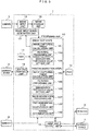
- Fig. 1 illustrates an example of a flowchart of processing after image capturing in the [read test step] of the processing unit 12 in the printing inspection device in the present example.
- the processing unit 12 in the printing inspection-device body 1 receives the output signal of the sensor 8, and then the image is read by the camera 3 at a predetermined timing.
- the read image is stored once in the image storage unit 16 in Step S1.
- Step S2 the filtering processing unit 122 in the processing unit 12 performs image improvement processing.
- Steps S3 to S6 represent processing of the binarization threshold value setting unit 123 in the processing unit 12.
- Step S3 regarding an image after filtering processing, binarization is performed with the brightness values for all gradations as a threshold value, and it is checked whether or not a two-dimensional code is read. For example, in a case of an image having 256 gradations, it is checked whether or not a two-dimensional code can be read, for all binarization threshold values of 0 to 255.
- the minimum brightness threshold value allowing a two-dimensional code to be read is set as MIN1, and the maximum brightness threshold value is set as MAX1.
- Step S4 it is determined whether there is another inspection sample on which the read test is to be performed. Regarding the number of inspection samples, one piece is possible, and two or more pieces are desirable to improve accuracy against variation.
- processing from Step S1 is also performed on the second and the subsequent inspection samples.
- the minimum brightness threshold values MIN2, MIN3, ... and the maximum brightness threshold values MAX2, MAX3, ... which are obtained by performing the processing up to Step S3 are obtained.
- the minimum brightness threshold values and the maximum brightness threshold values corresponding to the number of inspection samples are obtained.
- the average values are obtained from the brightness threshold values and set as the minimum brightness value MIN and the maximum brightness value MAX.
- Step S5 the minimum brightness value MIN and the maximum brightness value MAX are transmitted to the input and output unit 18 and displayed on the monitor 2.
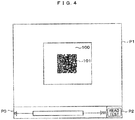
- Fig. 4 illustrates a display example.
- a two-dimensional code-image display portion P1 represents an image capturing region of the camera 3.
- a white region 100 including a two-dimensional code image at the center is a reading region.
- the reading region is set on an inspection condition setting screen (not illustrated).
- the captured image is located out of this region, the product is considered as a printed matter having a printing position deviation which is larger than an allowable range, and thus is determined as a defective product.
- As an example of a two-dimensional code image 101 at the center of the region 100 an image of a QR code (registered trademark) is displayed.
- QR code registered trademark
- Step S3 When a "read test” button is pressed, Step S3 is performed. The result is displayed on the left of the "read test” button. "0" indicates the minimum value of the binarization threshold value for performing the read test, and "255" indicates the maximum value of the binarization threshold value for performing the read test. A rectangle between the numerical values indicates the range of the binarization threshold value allowing a two-dimensional code to be read. Fig. 4 illustrates that a two-dimensional code can be read in a range of the binarization threshold value from "51" to "198".
- Step S6 the median value is obtained from the minimum value MIN and the maximum value MAX of the binarization threshold values allowing a two-dimensional code to be read, and is set as the binarization threshold value when the printing inspection is performed.
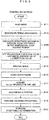
- Fig. 5 illustrates an example of a flowchart of processing after image capturing in the "printing inspection step" of the processing unit 12 according to the printing inspection device of the present example.
- the processing unit 12 in the printing inspection-device body 1 receives the output signal of the sensor 8, and then the camera 3 reads an image at a predetermined timing.
- Step S11 the read image is stored once in the image storage unit 16.
- Step S12 the filtering processing unit 125 in the processing unit 12 performs image improvement processing.
- Step S13 the binarization threshold value setting unit 126 sets the median value obtained in the "read test" as the binarization threshold value.
- Step S14 the image binarization processing unit 127 creates a binary image from a multi-level image with the binarization threshold value set in Step S13.
- the two-dimensional code computation unit 128 performs Steps S15 to S19.
- Step S15 investigation of a finder (pattern for position detection) is performed based on the binary image.
- Step S17 information (Version and the like) necessary for acquiring data is read based on the position of the finder.
- Step S18 data is taken based on information obtained in Step S17.
- Step S19 data (coded data) acquired in Step 18 is decoded to restore original data.
- the reading determination unit 129 performs acceptance determination on the read data.
- the processing unit 12 performs the [printing inspection step], not the [read test step]. Similar to Fig. 5 , an image is captured in Step S11, and filtering processing is performed in Step S12. Then, in Step S14, a binary image is created from a multi-level image by using the binarization threshold value set as the default value in Step S13. In Step S15, the finder investigation is performed based on the binary image. In Step S16, it is determined whether or not the finder inspection is possible. When finder investigation is possible, the multiplication multiplier for determining the binarization threshold value is changed in Step S21. In Step S13, re-setting of the binarization threshold value, image binarization, and finder investigation are performed using the changed multiplication multiplier. Steps S21, S13, S14, S15, and S16 are repeated until the finder inspection is possible.
- all gradation values are used as the binarization threshold value by the [read test], the binarization of a multi-level image is performed to check whether or not reading of a two-dimensional code is possible, and the optimum binarization threshold value is set in advance.
- the binarization threshold value is set in advance.
- the printing inspection device in the present example captures an image including a two-dimensional code printed by a general-purpose printer such as an ink jet printer, in a form of a multi-level image.
- the printing inspection device creates a binary image from the multi-level image with a predetermined binarization threshold value, and then performs decoding. According to the printing inspection device, it is possible to obtain the optimum binarization threshold value without an occurrence of a situation in which the processing time becomes long by repeating binarization or a product is determined as a defective product because the code is not read within a desired time.
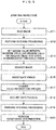
- Fig. 7 illustrates an example of a flowchart of processing after image capturing in the [read test step] of the processing unit 12 in the printing inspection device in the present example. Similar to the case in Fig. 1 , an image is captured in Step S1, filtering processing is performed in Step S2, and the minimum value MIN1 and the maximum value MAX1 of brightness values allowing reading are obtained in Step S3.
- an average brightness value AVE1 for all pixels in a two-dimensional code reading region is calculated in Step S31. Similar to the case in Fig. 1 , regarding the number of inspection samples, one piece is possible, and two or more pieces are desirable to improve accuracy against variation. When two or more inspection samples are provided, processing from Step S1 is also performed on the second and the subsequent inspection samples.
- the minimum brightness threshold values MIN2, MIN3, ..., the maximum brightness threshold values MAX2, MAX3, ..., and all-pixel average brightness values AVE2, AVE3, ... in the reading region, which are obtained by performing processing up to Step S31 are obtained.
- the minimum brightness threshold values, the maximum brightness threshold values, and the all-pixel average brightness values in the reading region which correspond to the number of inspection samples, are obtained.
- the average values are obtained from the obtained brightness threshold values and set as the minimum brightness value MIN, the maximum brightness value MAX, and the all-pixel average brightness value AVE in the reading region, respectively.
- Step S5 the minimum brightness value MIN, the maximum brightness value MAX, and the all-pixel average brightness value AVE in the reading region are transmitted to the input and output unit 18 and are displayed on the monitor 2.
- Step S6 the median value between the maximum value and the minimum value is obtained.
- Fig. 8 illustrates a display example. In the present example, a button for the binarization method selects "automatic” P4. As the result of the read test, which is displayed on the left of the "read test” button, similar to the case in Fig.
- Step S9 an image is captured in Step S11, and filtering processing is performed in Step S12. Then, the average brightness value for all pixels in the reading region is calculated in Step S33.
- Step S34 a numerical value obtained by adding the correction value obtained in the [read test step] to the average brightness value for all pixels in the reading region is set as the binarization threshold value.
- Step S14 a binary image is created from a multi-level image by using the binarization threshold value.
- the average brightness value for all pixels in the reading region is calculated, the numerical value obtained by adding the correction value to the average value is set as the binarization threshold value, and binarization of a multi-level image is performed with the binarization threshold value.
- the average values of the obtained numerical values are set as MIN and the maximum binarization threshold value MAX, respectively.
- a method of setting the maximum value of the minimum binarization threshold values MIN1, MIN2, ... as MIN and setting the minimum value of the maximum binarization threshold values MAX1, MAX2, ... as MAX is also effective.
- the processing unit performing the [read test step] and the processing unit performing the [printing inspection step] are set to be separate from each other.
- the processing units (for example, image capturing timing calculation units 121 and 124) that perform the same operation can be set as the same processing unit.
Landscapes
- Engineering & Computer Science (AREA)
- Physics & Mathematics (AREA)
- Theoretical Computer Science (AREA)
- General Physics & Mathematics (AREA)
- Computer Vision & Pattern Recognition (AREA)
- Health & Medical Sciences (AREA)
- Quality & Reliability (AREA)
- Electromagnetism (AREA)
- General Health & Medical Sciences (AREA)
- Toxicology (AREA)
- Artificial Intelligence (AREA)
- Image Processing (AREA)
- Investigating Materials By The Use Of Optical Means Adapted For Particular Applications (AREA)
- Image Analysis (AREA)
- Accessory Devices And Overall Control Thereof (AREA)
Abstract
Description
- The present invention relates to a printing inspection device and particularly relates to a printing inspection device suitable for reading a two-dimensional code (simply referred to as a "character" below because a symbol or the two-dimensional code is included in a character) with a camera and determining the quality of printing, the two-dimensional code in which, for example, characters and symbols such as the production date or a serial number printed by an inkjet printer and the like and information necessary for production history management are recorded.
- As the background art of a printing inspection device, there is
JP 2009-70061 A JP 2009-70061 A - Patent Document 1:
JP 2009-70061 A - Labeling of the production date, the expiration date, the production lot, and the like is legally required for packing containers for foods and chemicals. A printing device such as an ink jet printer is used to realize the labeling. The printing device is installed on a transport line (including a packing line) and performs printing on a packing container which is transported one after another. A printing inspection device that reads printing of the packing container determines whether or not printing by the printing device is correctly performed. Further, in recent years, in order to record various types of information necessary for production history management in addition to the above printing, it is increasing to simultaneously perform printing of two-dimensional codes capable of recording multiple pieces of information. Thus, it is also required to inspect whether information of the two-dimensional code is correctly printed.
- However, the device disclosed in
Patent Document 1 focuses only on the ratio of white and black. In practice, the position of a cell after binarization is determined to be largely shifted by the degree of position shift of the cell to the pixel, and thus it may not be possible to read the two-dimensional code. - Thus, an object of the present invention is to obtain a printing inspection device that obtains an optimum binarization threshold value in the printing inspection device that captures an image including a two-dimensional code printed by a general-purpose printer such as an ink jet printer, as a multi-level image, creates a binary image from the multi-level image with a predetermined binarization threshold value, and then performs decoding.
- To solve the above problems, for example, the configuration described in the claims is adopted. The present application includes a plurality of means for solving the above problems. According to an example, a printing inspection device reads printing including a two-dimensional code printed on a printing target. The printing inspection device includes means for inputting a recognition target including a two-dimensional code in a form of a multi-level image, image binarization means for binarizing the multi-level image with a predetermined binarization threshold value and outputting a binary image, two-dimensional code detection means for detecting a region of a two-dimensional code from the binary image, decoding means for decoding the two-dimensional code, and read test means for performing a read test. The read test means performs a read test by binarizing one or more inspection samples with brightness values for all gradations, as a threshold value, obtains a maximum value and a minimum value of readable brightness values, causes the obtained maximum value and minimum value to be displayed in a display portion, and sets a median value between the minimum value and the maximum value, as a binarization threshold value for a two-dimensional code image in a practical printing inspection.
- According to the present invention, it is possible to provide a printing inspection device capable of obtaining an optimum binarization threshold value when a binary image is created from a multi-level image with a predetermined binarization threshold value, and then decoding is performed.
-
-
Fig. 1 illustrates an example of a flowchart for describing processing after image capturing in a read test step of a processing unit in Example 1. -
Fig. 2 is a diagram illustrating an installation example of a printing inspection device in Example 1. -
Fig. 3 is a block diagram illustrating the printing inspection device in Example 1. -
Fig. 4 illustrates a display example of a monitor in Example 1. -
Fig. 5 illustrates an example of a flowchart for describing processing after image capturing in a printing inspection step of the processing unit in Example 1. -
Fig. 6 illustrates an example of a flowchart for describing processing after image capturing in a printing inspection step in a printing inspection device in the related art. -
Fig. 7 illustrates an example of a flowchart for describing processing after image capturing in a read test step of a processing unit in Example 2. -
Fig. 8 illustrates a display example of a monitor in Example 2. -
Fig. 9 illustrates an example of a flowchart for describing processing after image capturing in a printing inspection step of the processing unit in Example 2. - Hereinafter, examples of the present invention will be described with reference to the drawings.
-
Fig. 2 illustrates an installation example of a printing inspection device used in the present example. InFig. 2 , the printing inspection device includes alighting device 4, acamera 3, amonitor 2, a printing inspection-device body 1, an external device, and the like. Thelighting device 4 irradiates a printedmatter 6 with light having a light quantity sufficient to cause thecamera 3 to read a printed character. The printedmatter 6 is obtained in a manner that a printing device such as an ink jet printer 9 performs printing on a packing container for foods and chemicals. Thecamera 3 refers to image capturing means for reading an image including a character string, a two-dimensional code, or the like, which serves as an inspection target in the printedmatter 6 with which the light is irradiated. Themonitor 2 displays the read image or displays condition settings of an inspection and an inspection result. A processing unit and a lighting control unit are mounted in the printing inspection-device body 1. The processing unit performs processing, for example, extracting a print image from an image read from thecamera 3 and performs acceptance determination of an inspection target character. The lighting control unit controls the light quantity, the timing, and the like of lighting. The external device transmits various instructions of image processing and the like to the processing unit in the printing inspection-device body 1. - In manufacturing factories for beverages and canned PET bottles,
droplets 11 are discharged onto the surface of a bottle or a can being a product before shipment, by aprint head 10 of a dedicated ink jet printer 9 to perform printing of the expiration date, the serial number, a two-dimensional code, and the like. Aproduct 6 before shipment, on which printing is performed by the ink jet printer 9, is transported by aconveyor 5 or the like. The processing unit in the printing inspection-device body 1 detects an output signal from asensor 8 installed in the vicinity of the conveyor, and calculates an image capturing timing of thecamera 3. At a timing at which the product is transported to a position allowing thecamera 3 to recognize an inspection target character, thelighting device 4 such as an LED lighting performs irradiation with light, and thecamera 3 reads an image including the inspection target character. Then, a print image is transmitted into the printing inspection-device body 1. -
Fig. 3 is a block diagram illustrating an example of the printing inspection device in the present example. A program for recognition processing of a printing character string, a two-dimensional code, or the like or a program for acceptance determination of printing quality is stored in aROM 13. In addition, a reference character pattern of constituent characters of a character string as an inspection target, setting data input from theexternal device 7, and the like are stored in aRAM 13. Theprocessing unit 12 performs various types of processing related to the printing inspection. - Firstly, a read test is performed using a test inspection sample in order to determine a binarization threshold value. When the
processing unit 12 in the printing inspection-device body 1 receives the output signal of thesensor 8, an image capturingtiming calculation unit 121 in theprocessing unit 12 calculates an image capturing timing of the camera. An image inputsignal generation unit 17 notifies thecamera 3 of an image capturing timing in response to an instruction from theprocessing unit 12. In addition, in response to an instruction from theprocessing unit 12, thelighting control unit 19 controls the light quantity of thelighting device 4 and controls an emission timing of thelighting device 4 in accordance with an image reading timing of thecamera 3. - The image read by the
camera 3 is multi-level image data in which each pixel has a numerical value (referred to as a "brightness value" below) depending on the brightness among the number of gradations determined by the performance of the camera. The data is input to animage input unit 15 in the printing inspection-device body 1, and stored once in animage storage unit 16. Afiltering processing unit 122 in theprocessing unit 12 performs image improvement processing such as thinning and thickening on the captured image stored in theimage storage unit 16, in order to easily recognize a two-dimensional code. A binarization thresholdvalue setting unit 123 acquires an optimum binarization threshold value for the image subjected to filteringprocessing 122, in accordance with the procedure described later. - Then, the practical printing inspection is performed. With the hand similar to that in the read test, the output signal of the
sensor 8 is received. An image capturingtiming calculation unit 124 in theprocessing unit 12 calculates the image capturing timing of the camera. Thecamera 3 performs image capturing to obtain multi-level image data. Afiltering processing unit 125 in theprocessing unit 12 performs image improvement processing on the multi-level image data. A binarization thresholdvalue setting unit 126 sets the optimum binarization threshold value based on the binarization threshold value obtained in [read test step]. An imagebinarization processing unit 127 performs binarization processing using the binarization threshold value obtained by the binarization thresholdvalue setting unit 126, so as to create a binary image from the multi-level image. A two-dimensionalcode computation unit 128 detects a region of the two-dimensional code from the obtained binary image, reads data of the two-dimensional code, and decodes the two-dimensional code. Then, areading determination unit 129 performs acceptance determination and transmits the determination result to an input andoutput unit 18. The determination result is displayed on themonitor 2. When the determination result means failure, theexternal device 7 rejects the product as a defective product. Further, in the above series of processing, the print image, an inspection condition, and the like are also transmitted to the input andoutput unit 18 and then are displayed on themonitor 2. -
Fig. 1 illustrates an example of a flowchart of processing after image capturing in the [read test step] of theprocessing unit 12 in the printing inspection device in the present example. As described with reference toFig. 3 , theprocessing unit 12 in the printing inspection-device body 1 receives the output signal of thesensor 8, and then the image is read by thecamera 3 at a predetermined timing. The read image is stored once in theimage storage unit 16 in Step S1. - Then, in Step S2, the
filtering processing unit 122 in theprocessing unit 12 performs image improvement processing. Steps S3 to S6 represent processing of the binarization thresholdvalue setting unit 123 in theprocessing unit 12. In Step S3, regarding an image after filtering processing, binarization is performed with the brightness values for all gradations as a threshold value, and it is checked whether or not a two-dimensional code is read. For example, in a case of an image having 256 gradations, it is checked whether or not a two-dimensional code can be read, for all binarization threshold values of 0 to 255. The minimum brightness threshold value allowing a two-dimensional code to be read is set as MIN1, and the maximum brightness threshold value is set as MAX1. In Step S4, it is determined whether there is another inspection sample on which the read test is to be performed. Regarding the number of inspection samples, one piece is possible, and two or more pieces are desirable to improve accuracy against variation. When two or more inspection samples are provided, processing from Step S1 is also performed on the second and the subsequent inspection samples. The minimum brightness threshold values MIN2, MIN3, ... and the maximum brightness threshold values MAX2, MAX3, ... which are obtained by performing the processing up to Step S3 are obtained. In addition, the minimum brightness threshold values and the maximum brightness threshold values corresponding to the number of inspection samples are obtained. The average values are obtained from the brightness threshold values and set as the minimum brightness value MIN and the maximum brightness value MAX. - In Step S5, the minimum brightness value MIN and the maximum brightness value MAX are transmitted to the input and
output unit 18 and displayed on themonitor 2.Fig. 4 illustrates a display example. A two-dimensional code-image display portion P1 represents an image capturing region of thecamera 3. Awhite region 100 including a two-dimensional code image at the center is a reading region. The reading region is set on an inspection condition setting screen (not illustrated). When the captured image is located out of this region, the product is considered as a printed matter having a printing position deviation which is larger than an allowable range, and thus is determined as a defective product. As an example of a two-dimensional code image 101 at the center of theregion 100, an image of a QR code (registered trademark) is displayed. When a "read test" button is pressed, Step S3 is performed. The result is displayed on the left of the "read test" button. "0" indicates the minimum value of the binarization threshold value for performing the read test, and "255" indicates the maximum value of the binarization threshold value for performing the read test. A rectangle between the numerical values indicates the range of the binarization threshold value allowing a two-dimensional code to be read.Fig. 4 illustrates that a two-dimensional code can be read in a range of the binarization threshold value from "51" to "198". In Step S6, the median value is obtained from the minimum value MIN and the maximum value MAX of the binarization threshold values allowing a two-dimensional code to be read, and is set as the binarization threshold value when the printing inspection is performed. -
Fig. 5 illustrates an example of a flowchart of processing after image capturing in the "printing inspection step" of theprocessing unit 12 according to the printing inspection device of the present example. After the binarization threshold value is determined by the flowchart illustrated inFig. 1 , the practical printing inspection is performed by the flowchart illustrated inFig. 5 . Theprocessing unit 12 in the printing inspection-device body 1 receives the output signal of thesensor 8, and then thecamera 3 reads an image at a predetermined timing. In Step S11, the read image is stored once in theimage storage unit 16. - Then, in Step S12, the
filtering processing unit 125 in theprocessing unit 12 performs image improvement processing. In Step S13, the binarization thresholdvalue setting unit 126 sets the median value obtained in the "read test" as the binarization threshold value. In Step S14, the imagebinarization processing unit 127 creates a binary image from a multi-level image with the binarization threshold value set in Step S13. The two-dimensionalcode computation unit 128 performs Steps S15 to S19. In Step S15, investigation of a finder (pattern for position detection) is performed based on the binary image. In Step S17, information (Version and the like) necessary for acquiring data is read based on the position of the finder. In Step S18, data is taken based on information obtained in Step S17. In Step S19, data (coded data) acquired inStep 18 is decoded to restore original data. In Step S20, the readingdetermination unit 129 performs acceptance determination on the read data. - Here, the conventional example of the printing inspection device will be described with reference to
Fig. 6 . In the conventional example, theprocessing unit 12 performs the [printing inspection step], not the [read test step]. Similar toFig. 5 , an image is captured in Step S11, and filtering processing is performed in Step S12. Then, in Step S14, a binary image is created from a multi-level image by using the binarization threshold value set as the default value in Step S13. In Step S15, the finder investigation is performed based on the binary image. In Step S16, it is determined whether or not the finder inspection is possible. When finder investigation is possible, the multiplication multiplier for determining the binarization threshold value is changed in Step S21. In Step S13, re-setting of the binarization threshold value, image binarization, and finder investigation are performed using the changed multiplication multiplier. Steps S21, S13, S14, S15, and S16 are repeated until the finder inspection is possible. - As described above, in the present example, all gradation values are used as the binarization threshold value by the [read test], the binarization of a multi-level image is performed to check whether or not reading of a two-dimensional code is possible, and the optimum binarization threshold value is set in advance. Thus, it is possible to prevent an increase in processing time due to resetting of the binarization threshold value and performing of the processing.
- As described above, the printing inspection device in the present example captures an image including a two-dimensional code printed by a general-purpose printer such as an ink jet printer, in a form of a multi-level image. The printing inspection device creates a binary image from the multi-level image with a predetermined binarization threshold value, and then performs decoding. According to the printing inspection device, it is possible to obtain the optimum binarization threshold value without an occurrence of a situation in which the processing time becomes long by repeating binarization or a product is determined as a defective product because the code is not read within a desired time.
- In the present example, an example of a printing inspection device effective when the brightness of a captured image fluctuates by variations in the state of a printed matter and variations in the brightness of the lighting, and the like will be described with reference to
Figs. 7 and8 . -
Fig. 7 illustrates an example of a flowchart of processing after image capturing in the [read test step] of theprocessing unit 12 in the printing inspection device in the present example. Similar to the case inFig. 1 , an image is captured in Step S1, filtering processing is performed in Step S2, and the minimum value MIN1 and the maximum value MAX1 of brightness values allowing reading are obtained in Step S3. - Then, an average brightness value AVE1 for all pixels in a two-dimensional code reading region is calculated in Step S31. Similar to the case in
Fig. 1 , regarding the number of inspection samples, one piece is possible, and two or more pieces are desirable to improve accuracy against variation. When two or more inspection samples are provided, processing from Step S1 is also performed on the second and the subsequent inspection samples. The minimum brightness threshold values MIN2, MIN3, ..., the maximum brightness threshold values MAX2, MAX3, ..., and all-pixel average brightness values AVE2, AVE3, ... in the reading region, which are obtained by performing processing up to Step S31 are obtained. In addition, the minimum brightness threshold values, the maximum brightness threshold values, and the all-pixel average brightness values in the reading region, which correspond to the number of inspection samples, are obtained. The average values are obtained from the obtained brightness threshold values and set as the minimum brightness value MIN, the maximum brightness value MAX, and the all-pixel average brightness value AVE in the reading region, respectively. - In Step S5, the minimum brightness value MIN, the maximum brightness value MAX, and the all-pixel average brightness value AVE in the reading region are transmitted to the input and
output unit 18 and are displayed on themonitor 2. In Step S6, the median value between the maximum value and the minimum value is obtained. In Step S32, correction value = "median value" - "all-pixel average brightness value in reading region" is obtained.Fig. 8 illustrates a display example. In the present example, a button for the binarization method selects "automatic" P4. As the result of the read test, which is displayed on the left of the "read test" button, similar to the case inFig. 4 , the minimum value of "51" and the maximum value of "198" in a range of the binarization threshold value allowing reading are displayed, and the median value of "125" is displayed. In addition, "137" which is the all-pixel average brightness value in the reading region is displayed in P5. When a specific numerical value is intended to be determined by using the binarization threshold value as a fixed value, an operator can input the numerical value in this display region. Then, "-12" is stored as the correction value in theprocessing unit 12. - In the [printing inspection step] illustrated in
Fig. 9 , similar toFig. 5 , an image is captured in Step S11, and filtering processing is performed in Step S12. Then, the average brightness value for all pixels in the reading region is calculated in Step S33. In Step S34, a numerical value obtained by adding the correction value obtained in the [read test step] to the average brightness value for all pixels in the reading region is set as the binarization threshold value. In Step S14, a binary image is created from a multi-level image by using the binarization threshold value. - As described above, according to the present example, for each inspection of an inspection target, the average brightness value for all pixels in the reading region is calculated, the numerical value obtained by adding the correction value to the average value is set as the binarization threshold value, and binarization of a multi-level image is performed with the binarization threshold value. Thus, even when the brightness of the image fluctuates, it is possible to set the optimum binarization threshold value and read a two-dimensional code.
- Note that, the present invention is not limited to the above-described examples, and various modifications are included. For example, a case where an image of a two-dimensional code is a QR code (registered trademark) is displayed in the example. Similar processing can be applied to other two-dimensional codes.
- In addition, when two or more inspection samples are provided, in the present examples, the average values of the obtained numerical values (average value of MIN1, MIN2, ... is set as MIN, and average value of MAX1, MAX2, ... is set as MAX) are set as the minimum binarization threshold value MIN and the maximum binarization threshold value MAX, respectively. However, when there are large variations, for example, a method of setting the maximum value of the minimum binarization threshold values MIN1, MIN2, ... as MIN and setting the minimum value of the maximum binarization threshold values MAX1, MAX2, ... as MAX is also effective.
- In addition, in the
processing unit 12, the processing unit performing the [read test step] and the processing unit performing the [printing inspection step] are set to be separate from each other. The processing units (for example, image capturingtiming calculation units 121 and 124) that perform the same operation can be set as the same processing unit. -
- 1 Printing inspection-device body
- 2 Monitor
- 3 Camera
- 4 Lighting device
- 5 Conveyor
- 6 Printed matter
- 7 External device
- 8 Sensor
- 9 Ink jet printer
- 10 Print head
- 11 Droplet
- 12 Processing unit
- 13 ROM
- 14 RAM
- 15 Image input unit
- 16 Image storage unit
- 17 Image input signal generation unit
- 18 Input and output unit
- 19 Lighting control unit
- 121 Image capturing timing calculation unit in [read test step]
- 122 Filtering processing unit in [read test step]
- 123 Binarization threshold value setting unit in [read test step]
- 124 Image capturing timing calculation unit in [printing inspection step]
- 125 Filtering processing unit in [printing inspection step]
- 126 Binarization threshold value setting unit in [printing inspection step]
- 127 Image binarization processing unit
- 128 Two-dimensional code computation unit
- 129 Reading determination unit
- P1 Two-dimensional code-image display portion of monitor screen
- P2 [Read test] start button display portion
- P3 Read test result display portion
- P4 Display portion of "automatic" setting button for setting in which correction value is automatically added to binarization threshold value
- P5 Portion for displaying all-pixel average brightness value in reading region and inputting binarization threshold value
- 100 Reading region in image display portion of monitor screen
- 101 Two-dimensional code image in image display portion of monitor screen
Claims (2)
- A printing inspection device that reads printing including a two-dimensional code printed on a printing target, the device comprising:means for inputting a recognition target including a two-dimensional code in a form of a multi-level image;image binarization means for binarizing the multi-level image with a predetermined binarization threshold value and outputting a binary image;two-dimensional code detection means for detecting a region of a two-dimensional code from the binary image;decoding means for decoding the two-dimensional code; andread test means for performing a read test,wherein the read test meansperforms a read test by binarizing one or more inspection samples with brightness values for all gradations, as a threshold value,obtains a maximum value and a minimum value of readable brightness values,causes the obtained maximum value and minimum value to be displayed in a display portion, andsets a median value between the minimum value and the maximum value, as a binarization threshold value for a two-dimensional code image in a practical printing inspection.
- The printing inspection device according to claim 1,
wherein when the read test is performed,
an average brightness value for all pixels in a printing read region, and
a difference between the calculated average brightness value and the median value is obtained as a correction value,
in the practical printing inspection,
the average brightness value for all pixels in the printing read region is calculated for each inspection target, and
the multi-level image is binarized with a numerical value obtained by adding the correction value to the average value, as the binarization threshold value.
Applications Claiming Priority (2)
| Application Number | Priority Date | Filing Date | Title |
|---|---|---|---|
| JP2018186328 | 2018-10-01 | ||
| PCT/JP2019/037463 WO2020071188A1 (en) | 2018-10-01 | 2019-09-25 | Printing inspection device |
Publications (3)
| Publication Number | Publication Date |
|---|---|
| EP3862913A1 true EP3862913A1 (en) | 2021-08-11 |
| EP3862913A4 EP3862913A4 (en) | 2022-07-06 |
| EP3862913B1 EP3862913B1 (en) | 2025-05-21 |
Family
ID=70055010
Family Applications (1)
| Application Number | Title | Priority Date | Filing Date |
|---|---|---|---|
| EP19869212.1A Active EP3862913B1 (en) | 2018-10-01 | 2019-09-25 | Printing inspection device |
Country Status (5)
| Country | Link |
|---|---|
| US (1) | US11514256B2 (en) |
| EP (1) | EP3862913B1 (en) |
| JP (1) | JP7057433B6 (en) |
| CN (1) | CN112740218B (en) |
| WO (1) | WO2020071188A1 (en) |
Cited By (1)
| Publication number | Priority date | Publication date | Assignee | Title |
|---|---|---|---|---|
| EP4184381A1 (en) * | 2021-11-23 | 2023-05-24 | Virnect Inc. | Method and system for setting dynamic image threshold for two-dimensional identification code detection |
Families Citing this family (1)
| Publication number | Priority date | Publication date | Assignee | Title |
|---|---|---|---|---|
| JP2024145691A (en) * | 2023-03-31 | 2024-10-15 | 株式会社キーエンス | Image Processing Device |
Family Cites Families (22)
| Publication number | Priority date | Publication date | Assignee | Title |
|---|---|---|---|---|
| JP2004054529A (en) * | 2002-07-18 | 2004-02-19 | Sharp Corp | Two-dimensional code reading method, two-dimensional code reading program, recording medium of the two-dimensional code reading program, and two-dimensional code reading device |
| JP2005165949A (en) * | 2003-12-05 | 2005-06-23 | Toshiba Social Automation Systems Co Ltd | Bar code reading method and bar code reading device |
| US7748810B2 (en) * | 2005-07-05 | 2010-07-06 | Seiko Epson Corporation | Image processing device, calibration table generator, image processing method, program product, and test pattern |
| JP4931703B2 (en) * | 2007-06-20 | 2012-05-16 | 富士フイルム株式会社 | Inspection method for liquid ejection device and cleaning device therefor |
| JP4728297B2 (en) * | 2007-07-30 | 2011-07-20 | 東芝テック株式会社 | Two-dimensional code reading apparatus and method |
| JP5145833B2 (en) | 2007-09-12 | 2013-02-20 | 株式会社リコー | Two-dimensional code reading device, two-dimensional code reading method, two-dimensional code reading program, and recording medium |
| JP5094504B2 (en) * | 2008-03-28 | 2012-12-12 | 富士フイルム株式会社 | Image forming apparatus |
| JP5160488B2 (en) * | 2009-03-23 | 2013-03-13 | 富士フイルム株式会社 | Dot position measuring method, apparatus and program |
| JP5478268B2 (en) * | 2010-01-13 | 2014-04-23 | 任天堂株式会社 | Image processing program, image processing apparatus, image processing method, and image processing system |
| JP2011233099A (en) * | 2010-04-30 | 2011-11-17 | Optoelectronics Co Ltd | Optical information reader and optical information reading method |
| US9031294B2 (en) * | 2010-07-23 | 2015-05-12 | National Institute Of Advanced Industrial Science And Technology | Region segmented image data creating system and feature extracting system for histopathological images |
| JP5555672B2 (en) * | 2011-07-14 | 2014-07-23 | 東芝テック株式会社 | Image processing device |
| CN104517089B (en) * | 2013-09-29 | 2017-09-26 | 北大方正集团有限公司 | A kind of Quick Response Code decodes system and method |
| CN104517110B (en) | 2013-09-29 | 2018-01-05 | 北大方正集团有限公司 | The binarization method and system of a kind of image in 2 D code |
| US10102463B2 (en) * | 2015-01-13 | 2018-10-16 | A.T Communications Co., Ltd. | Two-dimensional code generation device, two-dimensional code generation method, and non-transitory computer-readable recording medium |
| JP6675831B2 (en) * | 2015-03-27 | 2020-04-08 | 株式会社日立産機システム | Print inspection method, print inspection apparatus using the same, and print inspection apparatus main body |
| JP5792409B1 (en) * | 2015-04-07 | 2015-10-14 | 株式会社フューチャーアプリケーション | Optical reader and optical reading program |
| JP2016218816A (en) * | 2015-05-22 | 2016-12-22 | ローランドディー.ジー.株式会社 | Identity mark marking quality evaluation device, and identity mark marking quality evaluation method |
| JP2019006009A (en) * | 2017-06-23 | 2019-01-17 | キヤノン株式会社 | Image forming apparatus, control method thereof, and program |
| JP7062991B2 (en) * | 2018-02-13 | 2022-05-09 | コニカミノルタ株式会社 | Detection device, inkjet recording device and detection method |
| US10708406B2 (en) * | 2018-04-25 | 2020-07-07 | Future Dial, Inc. | Enhanced system and method for fully automated reverse logistics platform |
| US11205259B2 (en) * | 2019-01-28 | 2021-12-21 | Future Dial, Inc. | Enhanced automatic cosmetic grading |
-
2019
- 2019-09-25 EP EP19869212.1A patent/EP3862913B1/en active Active
- 2019-09-25 US US17/281,787 patent/US11514256B2/en active Active
- 2019-09-25 WO PCT/JP2019/037463 patent/WO2020071188A1/en not_active Ceased
- 2019-09-25 JP JP2020550321A patent/JP7057433B6/en active Active
- 2019-09-25 CN CN201980059461.7A patent/CN112740218B/en active Active
Cited By (1)
| Publication number | Priority date | Publication date | Assignee | Title |
|---|---|---|---|---|
| EP4184381A1 (en) * | 2021-11-23 | 2023-05-24 | Virnect Inc. | Method and system for setting dynamic image threshold for two-dimensional identification code detection |
Also Published As
| Publication number | Publication date |
|---|---|
| EP3862913B1 (en) | 2025-05-21 |
| EP3862913A4 (en) | 2022-07-06 |
| JPWO2020071188A1 (en) | 2021-09-02 |
| US11514256B2 (en) | 2022-11-29 |
| CN112740218B (en) | 2023-08-25 |
| CN112740218A (en) | 2021-04-30 |
| WO2020071188A1 (en) | 2020-04-09 |
| JP7057433B6 (en) | 2022-05-16 |
| JP7057433B2 (en) | 2022-04-19 |
| US20210383087A1 (en) | 2021-12-09 |
Similar Documents
| Publication | Publication Date | Title |
|---|---|---|
| US11270404B2 (en) | Digital watermarking applications | |
| US20250343866A1 (en) | Methods, apparatuses, and systems for detecting printing defects and contaminated components of a printer | |
| US10061946B2 (en) | Method and apparatus for industrial identification mark verification | |
| AU2009305437B2 (en) | Method and system for item identification | |
| US20110150346A1 (en) | Method and Apparatus for Identifying Embossed Characters | |
| KR20100032306A (en) | Information recognition processing apparatus and information recognition processing method | |
| US12380552B2 (en) | Apparatus for inspecting defect of printed material, method, and storage medium | |
| US11514256B2 (en) | Printing inspection device | |
| CN115302963A (en) | Bar code printing control method, system and medium based on machine vision | |
| JP7671944B2 (en) | Quality Inspection Equipment | |
| CN107408289B (en) | Printing inspection method, printing inspection apparatus using the same, and printing inspection apparatus main body | |
| JP6615835B2 (en) | Binarization processing program and binarization processing method in image inspection | |
| CN119688732B (en) | Printed product quality detection method, device and storage medium | |
| US20250265432A1 (en) | Reading an optical code | |
| US8184898B2 (en) | Analysis of leaded components | |
| CN106228097A (en) | bar code quality level detection method and device | |
| JP6082686B2 (en) | Printing inspection method | |
| JP4449480B2 (en) | Print image inspection method and inspection apparatus | |
| de Souza et al. | Test and Development of a Low-Cost Solution for Automatic Inspection of PET Bottle Codification | |
| CN113542730A (en) | A camera sensor testing method, device and storage medium | |
| CN118194893A (en) | Glass bottle laser code detection method and detection system |
Legal Events
| Date | Code | Title | Description |
|---|---|---|---|
| STAA | Information on the status of an ep patent application or granted ep patent |
Free format text: STATUS: THE INTERNATIONAL PUBLICATION HAS BEEN MADE |
|
| PUAI | Public reference made under article 153(3) epc to a published international application that has entered the european phase |
Free format text: ORIGINAL CODE: 0009012 |
|
| STAA | Information on the status of an ep patent application or granted ep patent |
Free format text: STATUS: REQUEST FOR EXAMINATION WAS MADE |
|
| 17P | Request for examination filed |
Effective date: 20210503 |
|
| AK | Designated contracting states |
Kind code of ref document: A1 Designated state(s): AL AT BE BG CH CY CZ DE DK EE ES FI FR GB GR HR HU IE IS IT LI LT LU LV MC MK MT NL NO PL PT RO RS SE SI SK SM TR |
|
| DAV | Request for validation of the european patent (deleted) | ||
| DAX | Request for extension of the european patent (deleted) | ||
| A4 | Supplementary search report drawn up and despatched |
Effective date: 20220603 |
|
| RIC1 | Information provided on ipc code assigned before grant |
Ipc: G06K 7/14 20060101ALI20220530BHEP Ipc: G06K 5/02 20060101ALI20220530BHEP Ipc: G06T 7/00 20170101ALI20220530BHEP Ipc: G06T 7/136 20170101ALI20220530BHEP Ipc: G06T 7/11 20170101AFI20220530BHEP |
|
| REG | Reference to a national code |
Ref country code: DE Ref legal event code: R079 Free format text: PREVIOUS MAIN CLASS: G06K0007140000 Ipc: G06T0007110000 Ref country code: DE Ref legal event code: R079 Ref document number: 602019070361 Country of ref document: DE Free format text: PREVIOUS MAIN CLASS: G06K0007140000 Ipc: G06T0007110000 |
|
| GRAP | Despatch of communication of intention to grant a patent |
Free format text: ORIGINAL CODE: EPIDOSNIGR1 |
|
| STAA | Information on the status of an ep patent application or granted ep patent |
Free format text: STATUS: GRANT OF PATENT IS INTENDED |
|
| RIC1 | Information provided on ipc code assigned before grant |
Ipc: G06K 7/14 20060101ALI20241210BHEP Ipc: G06K 5/02 20060101ALI20241210BHEP Ipc: G06T 7/00 20170101ALI20241210BHEP Ipc: G06T 7/136 20170101ALI20241210BHEP Ipc: G06T 7/11 20170101AFI20241210BHEP |
|
| INTG | Intention to grant announced |
Effective date: 20250113 |
|
| GRAS | Grant fee paid |
Free format text: ORIGINAL CODE: EPIDOSNIGR3 |
|
| GRAA | (expected) grant |
Free format text: ORIGINAL CODE: 0009210 |
|
| STAA | Information on the status of an ep patent application or granted ep patent |
Free format text: STATUS: THE PATENT HAS BEEN GRANTED |
|
| AK | Designated contracting states |
Kind code of ref document: B1 Designated state(s): AL AT BE BG CH CY CZ DE DK EE ES FI FR GB GR HR HU IE IS IT LI LT LU LV MC MK MT NL NO PL PT RO RS SE SI SK SM TR |
|
| REG | Reference to a national code |
Ref country code: GB Ref legal event code: FG4D |
|
| REG | Reference to a national code |
Ref country code: CH Ref legal event code: EP |
|
| REG | Reference to a national code |
Ref country code: DE Ref legal event code: R096 Ref document number: 602019070361 Country of ref document: DE |
|
| REG | Reference to a national code |
Ref country code: IE Ref legal event code: FG4D |
|
| REG | Reference to a national code |
Ref country code: NL Ref legal event code: MP Effective date: 20250521 |
|
| PG25 | Lapsed in a contracting state [announced via postgrant information from national office to epo] |
Ref country code: PT Free format text: LAPSE BECAUSE OF FAILURE TO SUBMIT A TRANSLATION OF THE DESCRIPTION OR TO PAY THE FEE WITHIN THE PRESCRIBED TIME-LIMIT Effective date: 20250922 Ref country code: FI Free format text: LAPSE BECAUSE OF FAILURE TO SUBMIT A TRANSLATION OF THE DESCRIPTION OR TO PAY THE FEE WITHIN THE PRESCRIBED TIME-LIMIT Effective date: 20250521 Ref country code: ES Free format text: LAPSE BECAUSE OF FAILURE TO SUBMIT A TRANSLATION OF THE DESCRIPTION OR TO PAY THE FEE WITHIN THE PRESCRIBED TIME-LIMIT Effective date: 20250521 |
|
| PGFP | Annual fee paid to national office [announced via postgrant information from national office to epo] |
Ref country code: DE Payment date: 20250716 Year of fee payment: 7 |
|
| REG | Reference to a national code |
Ref country code: LT Ref legal event code: MG9D |
|
| PG25 | Lapsed in a contracting state [announced via postgrant information from national office to epo] |
Ref country code: GR Free format text: LAPSE BECAUSE OF FAILURE TO SUBMIT A TRANSLATION OF THE DESCRIPTION OR TO PAY THE FEE WITHIN THE PRESCRIBED TIME-LIMIT Effective date: 20250822 Ref country code: NO Free format text: LAPSE BECAUSE OF FAILURE TO SUBMIT A TRANSLATION OF THE DESCRIPTION OR TO PAY THE FEE WITHIN THE PRESCRIBED TIME-LIMIT Effective date: 20250821 |
|
| PG25 | Lapsed in a contracting state [announced via postgrant information from national office to epo] |
Ref country code: NL Free format text: LAPSE BECAUSE OF FAILURE TO SUBMIT A TRANSLATION OF THE DESCRIPTION OR TO PAY THE FEE WITHIN THE PRESCRIBED TIME-LIMIT Effective date: 20250521 Ref country code: PL Free format text: LAPSE BECAUSE OF FAILURE TO SUBMIT A TRANSLATION OF THE DESCRIPTION OR TO PAY THE FEE WITHIN THE PRESCRIBED TIME-LIMIT Effective date: 20250521 |
|
| PG25 | Lapsed in a contracting state [announced via postgrant information from national office to epo] |
Ref country code: BG Free format text: LAPSE BECAUSE OF FAILURE TO SUBMIT A TRANSLATION OF THE DESCRIPTION OR TO PAY THE FEE WITHIN THE PRESCRIBED TIME-LIMIT Effective date: 20250521 |
|
| PG25 | Lapsed in a contracting state [announced via postgrant information from national office to epo] |
Ref country code: HR Free format text: LAPSE BECAUSE OF FAILURE TO SUBMIT A TRANSLATION OF THE DESCRIPTION OR TO PAY THE FEE WITHIN THE PRESCRIBED TIME-LIMIT Effective date: 20250521 |
|
| PG25 | Lapsed in a contracting state [announced via postgrant information from national office to epo] |
Ref country code: RS Free format text: LAPSE BECAUSE OF FAILURE TO SUBMIT A TRANSLATION OF THE DESCRIPTION OR TO PAY THE FEE WITHIN THE PRESCRIBED TIME-LIMIT Effective date: 20250821 |
|
| PG25 | Lapsed in a contracting state [announced via postgrant information from national office to epo] |
Ref country code: IS Free format text: LAPSE BECAUSE OF FAILURE TO SUBMIT A TRANSLATION OF THE DESCRIPTION OR TO PAY THE FEE WITHIN THE PRESCRIBED TIME-LIMIT Effective date: 20250921 |
|
| PG25 | Lapsed in a contracting state [announced via postgrant information from national office to epo] |
Ref country code: LV Free format text: LAPSE BECAUSE OF FAILURE TO SUBMIT A TRANSLATION OF THE DESCRIPTION OR TO PAY THE FEE WITHIN THE PRESCRIBED TIME-LIMIT Effective date: 20250521 |
|
| REG | Reference to a national code |
Ref country code: AT Ref legal event code: MK05 Ref document number: 1797448 Country of ref document: AT Kind code of ref document: T Effective date: 20250521 |
|
| PG25 | Lapsed in a contracting state [announced via postgrant information from national office to epo] |
Ref country code: SM Free format text: LAPSE BECAUSE OF FAILURE TO SUBMIT A TRANSLATION OF THE DESCRIPTION OR TO PAY THE FEE WITHIN THE PRESCRIBED TIME-LIMIT Effective date: 20250521 Ref country code: AT Free format text: LAPSE BECAUSE OF FAILURE TO SUBMIT A TRANSLATION OF THE DESCRIPTION OR TO PAY THE FEE WITHIN THE PRESCRIBED TIME-LIMIT Effective date: 20250521 Ref country code: DK Free format text: LAPSE BECAUSE OF FAILURE TO SUBMIT A TRANSLATION OF THE DESCRIPTION OR TO PAY THE FEE WITHIN THE PRESCRIBED TIME-LIMIT Effective date: 20250521 |
|
| PG25 | Lapsed in a contracting state [announced via postgrant information from national office to epo] |
Ref country code: CZ Free format text: LAPSE BECAUSE OF FAILURE TO SUBMIT A TRANSLATION OF THE DESCRIPTION OR TO PAY THE FEE WITHIN THE PRESCRIBED TIME-LIMIT Effective date: 20250521 |
|
| PG25 | Lapsed in a contracting state [announced via postgrant information from national office to epo] |
Ref country code: EE Free format text: LAPSE BECAUSE OF FAILURE TO SUBMIT A TRANSLATION OF THE DESCRIPTION OR TO PAY THE FEE WITHIN THE PRESCRIBED TIME-LIMIT Effective date: 20250521 |
|
| PG25 | Lapsed in a contracting state [announced via postgrant information from national office to epo] |
Ref country code: RO Free format text: LAPSE BECAUSE OF FAILURE TO SUBMIT A TRANSLATION OF THE DESCRIPTION OR TO PAY THE FEE WITHIN THE PRESCRIBED TIME-LIMIT Effective date: 20250521 Ref country code: SK Free format text: LAPSE BECAUSE OF FAILURE TO SUBMIT A TRANSLATION OF THE DESCRIPTION OR TO PAY THE FEE WITHIN THE PRESCRIBED TIME-LIMIT Effective date: 20250521 |
|
| PG25 | Lapsed in a contracting state [announced via postgrant information from national office to epo] |
Ref country code: IT Free format text: LAPSE BECAUSE OF FAILURE TO SUBMIT A TRANSLATION OF THE DESCRIPTION OR TO PAY THE FEE WITHIN THE PRESCRIBED TIME-LIMIT Effective date: 20250521 |
|
| REG | Reference to a national code |
Ref country code: DE Ref legal event code: R097 Ref document number: 602019070361 Country of ref document: DE |
|
| PLBE | No opposition filed within time limit |
Free format text: ORIGINAL CODE: 0009261 |
|
| STAA | Information on the status of an ep patent application or granted ep patent |
Free format text: STATUS: NO OPPOSITION FILED WITHIN TIME LIMIT |
|
| REG | Reference to a national code |
Ref country code: CH Ref legal event code: L10 Free format text: ST27 STATUS EVENT CODE: U-0-0-L10-L00 (AS PROVIDED BY THE NATIONAL OFFICE) Effective date: 20260402 |
|
| 26N | No opposition filed |
Effective date: 20260224 |
|
| REG | Reference to a national code |
Ref country code: CH Ref legal event code: H13 Free format text: ST27 STATUS EVENT CODE: U-0-0-H10-H13 (AS PROVIDED BY THE NATIONAL OFFICE) Effective date: 20260504 |