EP3862851A1 - Displaying a window in an augmented reality view - Google Patents
Displaying a window in an augmented reality view Download PDFInfo
- Publication number
- EP3862851A1 EP3862851A1 EP21153155.3A EP21153155A EP3862851A1 EP 3862851 A1 EP3862851 A1 EP 3862851A1 EP 21153155 A EP21153155 A EP 21153155A EP 3862851 A1 EP3862851 A1 EP 3862851A1
- Authority
- EP
- European Patent Office
- Prior art keywords
- window
- new
- previous
- placetime
- processor
- Prior art date
- Legal status (The legal status is an assumption and is not a legal conclusion. Google has not performed a legal analysis and makes no representation as to the accuracy of the status listed.)
- Granted
Links
Images


Classifications
-
- G—PHYSICS
- G06—COMPUTING OR CALCULATING; COUNTING
- G06T—IMAGE DATA PROCESSING OR GENERATION, IN GENERAL
- G06T11/00—Two-dimensional [2D] image generation
-
- G—PHYSICS
- G06—COMPUTING OR CALCULATING; COUNTING
- G06F—ELECTRIC DIGITAL DATA PROCESSING
- G06F3/00—Input arrangements for transferring data to be processed into a form capable of being handled by the computer; Output arrangements for transferring data from processing unit to output unit, e.g. interface arrangements
- G06F3/01—Input arrangements or combined input and output arrangements for interaction between user and computer
- G06F3/011—Arrangements for interaction with the human body, e.g. for user immersion in virtual reality
-
- G—PHYSICS
- G06—COMPUTING OR CALCULATING; COUNTING
- G06F—ELECTRIC DIGITAL DATA PROCESSING
- G06F3/00—Input arrangements for transferring data to be processed into a form capable of being handled by the computer; Output arrangements for transferring data from processing unit to output unit, e.g. interface arrangements
- G06F3/14—Digital output to display device ; Cooperation and interconnection of the display device with other functional units
-
- G—PHYSICS
- G06—COMPUTING OR CALCULATING; COUNTING
- G06T—IMAGE DATA PROCESSING OR GENERATION, IN GENERAL
- G06T3/00—Geometric image transformations in the plane of the image
- G06T3/20—Linear translation of whole images or parts thereof, e.g. panning
-
- G—PHYSICS
- G06—COMPUTING OR CALCULATING; COUNTING
- G06T—IMAGE DATA PROCESSING OR GENERATION, IN GENERAL
- G06T3/00—Geometric image transformations in the plane of the image
- G06T3/40—Scaling of whole images or parts thereof, e.g. expanding or contracting
-
- G—PHYSICS
- G06—COMPUTING OR CALCULATING; COUNTING
- G06T—IMAGE DATA PROCESSING OR GENERATION, IN GENERAL
- G06T3/00—Geometric image transformations in the plane of the image
- G06T3/60—Rotation of whole images or parts thereof
-
- G—PHYSICS
- G06—COMPUTING OR CALCULATING; COUNTING
- G06T—IMAGE DATA PROCESSING OR GENERATION, IN GENERAL
- G06T2200/00—Indexing scheme for image data processing or generation, in general
- G06T2200/24—Indexing scheme for image data processing or generation, in general involving graphical user interfaces [GUIs]
Definitions
- the subj ect matter disclosed herein relates to displaying a window and more particularly relates to displaying a window in an augmented reality view.
- Augmented reality views change when the environment of an augmented reality device changes.
- An apparatus for displaying a window in an augmented reality view includes a processor and a memory that stores code executable by the processor.
- the processor detects a new augmented reality placetime comprising a new augmented reality position and/or a new augmented reality time of an augmented reality device.
- the processor calculates new window characteristics for a window at the new augmented reality placetime based on previous window characteristics.
- the processor further displays the window with the new window characteristics.
- a method and program product also perform the functions of the apparatus.
- embodiments may be embodied as a system, method or program product. Accordingly, embodiments may take the form of an entirely hardware embodiment, an entirely software embodiment (including firmware, resident software, micro-code, etc.) or an embodiment combining software and hardware aspects that may all generally be referred to herein as a "circuit," "module” or “system.” Furthermore, embodiments may take the form of a program product embodied in one or more computer readable storage devices storing machine readable code, computer readable code, and/or program code, referred hereafter as code. The storage devices may be tangible, non-transitory, and/or non-transmission. The storage devices may not embody signals. In a certain embodiment, the storage devices only employ signals for accessing code.
- modules may be implemented as a hardware circuit comprising custom VLSI circuits or gate arrays, off-the-shelf semiconductors such as logic chips, transistors, or other discrete components.
- a module may also be implemented in programmable hardware devices such as field programmable gate arrays, programmable array logic, programmable logic devices or the like.
- Modules may also be implemented in code and/or software for execution by various types of processors.
- An identified module of code may, for instance, comprise one or more physical or logical blocks of executable code which may, for instance, be organized as an object, procedure, or function. Nevertheless, the executables of an identified module need not be physically located together, but may comprise disparate instructions stored in different locations which, when joined logically together, comprise the module and achieve the stated purpose for the module.
- a module of code may be a single instruction, or many instructions, and may even be distributed over several different code segments, among different programs, and across several memory devices.
- operational data may be identified and illustrated herein within modules, and may be embodied in any suitable form and organized within any suitable type of data structure. The operational data may be collected as a single data set, or may be distributed over different locations including over different computer readable storage devices.
- the software portions are stored on one or more computer readable storage devices.
- the computer readable medium may be a computer readable storage medium.
- the computer readable storage medium may be a storage device storing the code.
- the storage device may be, for example, but not limited to, an electronic, magnetic, optical, electromagnetic, infrared, holographic, micromechanical, or semiconductor system, apparatus, or device, or any suitable combination of the foregoing.
- a storage device More specific examples (a non-exhaustive list) of the storage device would include the following: an electrical connection having one or more wires, a portable computer diskette, a hard disk, a random access memory (RAM), a read-only memory (ROM), an erasable programmable read-only memory (EPROM or Flash memory), or any suitable combination of the foregoing.
- a computer readable storage medium may be any tangible medium that can contain, or store a program for use by or in connection with an instruction execution system, apparatus, or device.
- Code for carrying out operations for embodiments may be written in any combination of one or more programming languages including an object oriented programming language such as Python, Ruby, R, Java, Java Script, Smalltalk, C++, C sharp, Lisp, Clojure, PHP, or the like, and conventional procedural programming languages, such as the "C" programming language, or the like, and/or machine languages such as assembly languages.
- the code may execute entirely on the user's computer, partly on the user's computer, as a stand-alone software package, entirely or partly on a head mounted display such as an augmented reality device, partly on the user's computer and partly on a remote computer or entirely on the remote computer or server.
- the remote computer may be connected to the user's computer through any type of network, including a local area network (LAN) or a wide area network (WAN), or the connection may be made to an external computer (for example, through the Internet using an Internet Service Provider).
- LAN local area network
- WAN wide area network
- Internet Service Provider an Internet Service Provider
- the code may also be stored in a storage device that can direct a computer, other programmable data processing apparatus, or other devices to function in a particular manner, such that the instructions stored in the storage device produce an article of manufacture including instructions which implement the function/act specified in the schematic flowchart diagrams and/or schematic block diagrams block or blocks.
- the code may also be loaded onto a computer, other programmable data processing apparatus, or other devices to cause a series of operational steps to be performed on the computer, other programmable apparatus or other devices to produce a computer implemented process such that the code which execute on the computer or other programmable apparatus provide processes for implementing the functions/acts specified in the flowchart and/or block diagram block or blocks.
- each block in the schematic flowchart diagrams and/or schematic block diagrams may represent a module, segment, or portion of code, which comprises one or more executable instructions of the code for implementing the specified logical function(s).
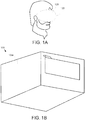
- FIG 1A is a perspective drawing illustrating one embodiment of an augmented reality (AR) device 120.
- the AR device 120 includes a camera 125.
- the AR device 120 may be worn by a user who views a display within the AR device 120.
- the AR view of the AR device 120 may include both the environment and images that are presented on the display by the AR device 120.
- FIG. 1B is a perspective drawing illustrating one embodiment of an AR view 100.
- the AR view 100 is presented to the user by a display of the AR device 120.
- the AR view 100 includes the environment 103a.
- the AR view 100 further includes a window 105 that comprises video, graphics, text, and the like that is superimposed over the environment 103a by the AR device 120.
- the window 105 is depicted as a flat screen, the window 105 may be presented with any shape and in either two or three dimensions.
- the window 105 is presented as though disposed on a surface of the environment 103a.
- a television window 105 may be presented as though disposed on a wall of a room.
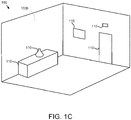
- FIG 1C is a perspective drawing illustrating one alternate embodiment of an AR view 100.
- a new environment 103b is captured by the camera 125 at a different AR position and/or AR time from the given AR position and time of the environment 103a of Figure 1B .
- the new environment 103b includes objects 110 that were not in the previous environment 103a.
- displaying the window 105 at the same location in the new environment 103b as was used in the original environment 103a may not be desirable.
- the embodiments determine a new location and other window characteristics for the window 105 in the new environment 103b.
- the embodiments detect a new AR placetime for the AR device 120 and calculate new window characteristics for the window 105 at the new AR placetime based on previous window characteristics at a previous environment 103a.
- the embodiments display the window 105 with the new characteristics. As a result, the window 105 is automatically repositioned to a new location within the new environment 103b, improving the efficiency and efficacy of the AR device 120 as will be described hereafter.
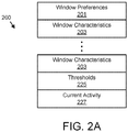
- FIG. 2A is a schematic block diagram illustrating one embodiment of AR data 200.
- the AR data 200 may be used to calculate the new window characteristics 103 for the window 105 and display the window 105 with the new window characteristics 203.
- the AR data 200 may be organized as a data structure in a memory.
- the AR data 200 includes window preferences 201, one or more window characteristics 203, thresholds 225, and current activity 227.
- the window preferences 201 may record user preferences for the placement of windows 105 within an AR view 100.
- the window preferences 201 may include a preferred window angular size, a docking preference, a preferred window angular orientation, and/or a preferred window density.
- the preferred window angular size may specify a maximum window angular size, a minimum angular window size, and/or an average window angular size.
- the window angular size is an apparent maximum window dimension measured in degrees of the window 105 as seen from the user's eye. Alternatively, the window angular size may be measured in pixels.
- the docking preference may specify whether a window 105 is presented as docked, wherein the window 105 appears disposed on a surface such as a wall, or presented undocked as though floating in the air.
- the preferred window angular orientation may specify a maximum angular difference between a vector from the user's eye to the center of the window 105, and an apparent normal vector radiating from the center of the window 105.
- the preferred window density may specify a percentage of the AR view 100 over which windows 105 are overlaid. In one embodiment, the preferred window density is for a specified view angle such as a 30 degree angle as measured from the user's eye. Alternatively, the preferred window density may be for the total pixels presented by the AR device 120.
- the window characteristics 203 describe presentation characteristics of a window 105.
- the window characteristics 203 are described in more detail in Figure 2B .
- the thresholds 225 include one or more thresholds used to make automatic decisions.
- the current activity 227 records the current activity of the user with the AR device 120 in the environment 103.
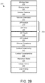
- FIG. 2B is a schematic block diagram illustrating one embodiment of the window characteristics 203.
- the window characteristics 203 maybe organized as a data structure in a memory.
- the window characteristics 203 include a window size 205, a window angle 207, a window distance 209, a window orientation 211, the AR position 213, the AR time 231, AR people 235, an AR context 237, a window timestamp 215, a surface relationship 217, surface characteristics 219, a reposition status 221, a usage history 223, and user activity 229.
- An AR placetime 233 may comprise the AR position 213, AR time 231, AR people 235, and/or AR context 237.
- the window size 205 may record the size of the window 105 as an angle is viewed from the user's eye and/or in pixels.
- a window 105 may have a window size 205 of 15 degrees and/or 300 pixels.
- the window angle 207 may specify an angle of an apparent normal vector from a center of the window to a vector from the user's eye to the center of the window 105.
- the window distance 209 may be an apparent distance in the environment 103 from the user's eye to the window 105.
- the window orientation 211 may record whether the window 105 is presented in landscape or portrait.
- the AR position 213 specifies the position of the window 105 within the AR view 100.
- the AR time 231 may record a time interval when the window 105 was displayed at the AR position 213.
- the AR people 235 may record other people in the AR view 100 when the window 105 was displayed.
- the AR context 237 records the context of usage of the AR device 120 and/or activity displayed in the AR view 100.
- the window timestamp 215 records when the window 105 was last displayed using the window characteristics 203.
- the surface relationship 217 records whether the window 105 was docked to a surface such as a wall.
- the surface characteristics 219 record characteristics of any surface that the window 105 was docked to.
- the surface characteristics 219 may include a surface color, a surface uniformity, and object density, and the like.
- the surface color may record the average color of the surface.
- the surface uniformity may record an average deviation from the surface color across the surface.
- the object density may record a percentage of the surface area of the surface that includes objects that form discontinuities in the surface.
- the reposition status 229 records details of the last repositioning of the window 105 within the AR view 100.
- the usage history 223 records uses of the window 105.
- the user activity 229 records other interactions of the user with the AR view 100 while the window 105 was active.
- FIG 3 is a perspective drawing illustrating one embodiment of an AR view 100 with new window characteristics 203.
- the AR view 100 of the new environment 103b of Figure 1C is shown.
- the window 105 is displayed with new window characteristics 203 that conform to the new, current environment 103b.
- the user may view the window 105 in the new environment 103b, giving user access to customary information in the window 105 and improving the function and efficiency of the AR device 120.
- FIG 4 is a schematic block diagram illustrating one embodiment of the AR device 120.
- the AR device 120 includes a processor 405, a memory 410, communication hardware 415, the camera 125, and a display 130.
- the memory 410 may comprise a semiconductor storage device.
- the memory 410 stores code.
- the processor 405 executes the code.
- the communication hardware 415 communicates the camera 125, the display 130, and/or with other devices such as a network, server, and/or computer.
- the display 130 may be disposed in the AR device 120 and may be an optical engine of the AR device 120.
- Figure 5 is a schematic flow chart diagram illustrating one embodiment of a window display method 500.
- the method 500 may display the window 105 with the new window characteristics 203.
- the method 500 may be performed by the AR device 120 and/or the processor 405.
- the method 500 starts, and in one embodiment, the processor 405 records 501 the window characteristics 203 for the AR view 100 in the previous environment 103a.
- the processor 405 may record a plurality of previous window characteristics 203 for each environment 103 in which the AR device 120 is employed.
- the processor 405 further detects 503 a new AR placetime 233 using the camera 125.
- the new AR placetime 233 may be different from the most recent previous AR placetime 233.
- the new AR placetime 233 may be different from all previous AR placetimes 233.
- the new AR placetime 233 is detected from a new AR position 213. For example, if the AR device 120 is used at a new AR position 213, the new AR placetime 233 may be detected.
- the new AR placetime 233 may be detected 503 from a new AR time 231. For example, if the AR device 120 is used at a new AR time 231, the new AR placetime 233 may be detected 503. The new AR placetime 233 may be detected 503 in response to elapsed time from the window timestamp 215 exceeding an elapsed time threshold 225.
- the new AR placetime 233 is detected 503 in response to new AR people 235 in the environment 103. For example, if a new colleague is visible in the AR view 100, a new AR placetime 233 may be detected 503.
- the new AR placetime 233 may also be detected 503 from a change in AR context 237. For example, if the AR device 120 was moving in the previous environment 103a and is stationary in the new, current environment 103b, the new AR placetime 233 may be detected 503. In one embodiment, the new AR placetime 233 is detected 503 from a change in any of the window characteristics 203. The new AR placetime 233 may be automatically detected 503.
- the processor 405 may determine 505 whether to redeploy the window 105 within the AR view 100.
- the window 105 may be redeployed with new window characteristics 203.
- the processor 405 queries to reposition the window 105.
- the processor 405 may query the user as to whether to reposition the window 105. For example, the processor 405 may present a "Reposition Window" option to the user.
- the processor 405 may determine 505 to redeploy the window 105 in response to an affirmative reply from the user.
- the window 105 may be displayed with the new window characteristics 203 in response to being directed to reposition the window 105.
- the processor 405 determines 505 to redeploy the window 105 within the AR view 100 if the usage history 223 and/or user activity 229 of a previous window characteristic 203 is similar to the current activity 227. For example, if the user was previously performing an inspection user activity 229 recorded in a previous window characteristic 203 and the user is now performing an inspection current activity 227, the processor 405 may determine 505 to redeploy the window 105.
- the processor 405 determines 505 to redeploy the window 105 within the AR view 100 if the current time is within a daily time interval of the AR time 231 of a previous window characteristic 203.
- a daily time interval is a range of times on any time and/or a specific day. For example, 10:00 to 12:00 on Monday may be a daily time interval.
- the processor 405 automatically determines 505 to redeploy each window 105 from a most recent previous environment 103 within the AR view 100. For example, if a first window 105 was displayed the last time the AR device 120 was used, the first window 105 is determined to be redeployed.
- the processor 405 determines 505 not to redeploy the window 105 if the elapsed time from the window timestamp 215 exceeds a significant time threshold 225. If the processor 405 determines 505 not to redeploy the window 105, the processor 405 may query 513 the user for new window characteristics 213. For example, the processor 405 may present a user interface that queries 513 for the new window characteristics 213. The processor 405 may further receive the new window characteristics 213 from the user.
- the processor 405 may determine 507 the window preferences 201 for the window 105 displayed at one or more previous AR placetimes 233.
- the window preferences 201 are calculated to conform to one or more elements of one or more previous window characteristics 203.
- the window preferences 201 may be received from the user.
- the processor 405 may calculate 509 the new window characteristics 203 for the window 105.
- the new window characteristics 203 may be calculated 509 for the new AR placetime 233.
- the new window characteristics 203 are based on one instance of previous window characteristics 203.
- the one instance of previous window characteristics 203 may be selected based on the current activity 227.
- the one instance of previous window characteristics 203 may record user activity 229 that is equivalent to the current activity 227 of the user.
- the new window characteristics 203 are based on an instance of the previous window characteristics 203 with the usage history 223 that conforms to the current activity 227.
- the new window characteristics 203 may be based on an instance of the previous window characteristics 203 with a reposition status 221 that is most similar to the current activity 227.
- the new window characteristics 203 are based on an instance of the previous window characteristics 203 with surface characteristics 219 that are most similar to the surface characteristics 219 of the current, new environment 103b.
- the new window characteristics 203 are calculated 509 based on an average, median, and/or mean of the plurality of previous window characteristics 203.
- the new window characteristics 203 may be calculated 509 based on an average, median, and/or mean of one or more elements of the plurality of previous window characteristics 203.
- the processor 405 may calculate 509 the new window characteristics 203 for the window 105 at a new AR placetime 233 based on previous window characteristics 203. For example, one or more of the window size 205, the window angle 207, the window distance 209, and/or window orientation 211 may be within a similarity threshold 225 of the window size 205, the window angle 207, the window distance 209, and/or window orientation 211 of the previous window characteristics 203.
- the similarity threshold may be plus or minus 5 to 20 percent.
- the new window characteristics 203 may conform to the window preferences 201.
- the processor 405 may display 511 the window 105 with the new window characteristics 203 and the method 500 ends.
- the window 105 may be displayed 511 in the AR view 100 for the new environment 103b.
- the embodiments detect the new AR placetime 233 and calculate new window characteristics for the window 105 at the new AR placetime 233 based on previous window characteristics 203.
- the window 105 is displayed with the new window characteristics 203.
- the window 105 and information displayed thereon is automatically available to the user through the AR device 120 when the user moves between environments 103, improving the efficiency and effectiveness of the AR device 120 in presenting information to the user.
Landscapes
- Engineering & Computer Science (AREA)
- Theoretical Computer Science (AREA)
- Physics & Mathematics (AREA)
- General Physics & Mathematics (AREA)
- General Engineering & Computer Science (AREA)
- Human Computer Interaction (AREA)
- User Interface Of Digital Computer (AREA)
Abstract
Description
- The subj ect matter disclosed herein relates to displaying a window and more particularly relates to displaying a window in an augmented reality view.
- Augmented reality views change when the environment of an augmented reality device changes.
- An apparatus for displaying a window in an augmented reality view is disclosed. The apparatus includes a processor and a memory that stores code executable by the processor. The processor detects a new augmented reality placetime comprising a new augmented reality position and/or a new augmented reality time of an augmented reality device. The processor calculates new window characteristics for a window at the new augmented reality placetime based on previous window characteristics. The processor further displays the window with the new window characteristics. A method and program product also perform the functions of the apparatus.
- A more particular description of the embodiments briefly described above will be rendered by reference to specific embodiments that are illustrated in the appended drawings. Understanding that these drawings depict only some embodiments and are not therefore to be considered to be limiting of scope, the embodiments will be described and explained with additional specificity and detail through the use of the accompanying drawings, in which:
-
Figure 1A is a perspective drawing illustrating one embodiment of an augmented reality device; -
Figure 1B is a perspective drawing illustrating one embodiment of an augmented reality view; -
Figure 1C is a perspective drawing illustrating one alternate embodiment of an augmented reality view; -
Figure 2A is a schematic block diagram illustrating one embodiment of augmented reality data; -
Figure 2B is a schematic block diagram illustrating one embodiment of window characteristics; -
Figure 3 is a perspective drawing illustrating one embodiment of an augmented reality view with new window characteristics; -
Figure 4 is a schematic block diagram illustrating one embodiment of a computer; and -
Figure 5 is a schematic flow chart diagram illustrating one embodiment of a window display method. - As will be appreciated by one skilled in the art, aspects of the embodiments may be embodied as a system, method or program product. Accordingly, embodiments may take the form of an entirely hardware embodiment, an entirely software embodiment (including firmware, resident software, micro-code, etc.) or an embodiment combining software and hardware aspects that may all generally be referred to herein as a "circuit," "module" or "system." Furthermore, embodiments may take the form of a program product embodied in one or more computer readable storage devices storing machine readable code, computer readable code, and/or program code, referred hereafter as code. The storage devices may be tangible, non-transitory, and/or non-transmission. The storage devices may not embody signals. In a certain embodiment, the storage devices only employ signals for accessing code.
- Many of the functional units described in this specification have been labeled as modules, in order to more particularly emphasize their implementation independence. For example, a module may be implemented as a hardware circuit comprising custom VLSI circuits or gate arrays, off-the-shelf semiconductors such as logic chips, transistors, or other discrete components. A module may also be implemented in programmable hardware devices such as field programmable gate arrays, programmable array logic, programmable logic devices or the like.
- Modules may also be implemented in code and/or software for execution by various types of processors. An identified module of code may, for instance, comprise one or more physical or logical blocks of executable code which may, for instance, be organized as an object, procedure, or function. Nevertheless, the executables of an identified module need not be physically located together, but may comprise disparate instructions stored in different locations which, when joined logically together, comprise the module and achieve the stated purpose for the module.
- Indeed, a module of code may be a single instruction, or many instructions, and may even be distributed over several different code segments, among different programs, and across several memory devices. Similarly, operational data may be identified and illustrated herein within modules, and may be embodied in any suitable form and organized within any suitable type of data structure. The operational data may be collected as a single data set, or may be distributed over different locations including over different computer readable storage devices. Where a module or portions of a module are implemented in software, the software portions are stored on one or more computer readable storage devices.
- Any combination of one or more computer readable medium may be utilized. The computer readable medium may be a computer readable storage medium. The computer readable storage medium may be a storage device storing the code. The storage device may be, for example, but not limited to, an electronic, magnetic, optical, electromagnetic, infrared, holographic, micromechanical, or semiconductor system, apparatus, or device, or any suitable combination of the foregoing.
- More specific examples (a non-exhaustive list) of the storage device would include the following: an electrical connection having one or more wires, a portable computer diskette, a hard disk, a random access memory (RAM), a read-only memory (ROM), an erasable programmable read-only memory (EPROM or Flash memory), or any suitable combination of the foregoing. In the context of this document, a computer readable storage medium may be any tangible medium that can contain, or store a program for use by or in connection with an instruction execution system, apparatus, or device.
- Code for carrying out operations for embodiments may be written in any combination of one or more programming languages including an object oriented programming language such as Python, Ruby, R, Java, Java Script, Smalltalk, C++, C sharp, Lisp, Clojure, PHP, or the like, and conventional procedural programming languages, such as the "C" programming language, or the like, and/or machine languages such as assembly languages. The code may execute entirely on the user's computer, partly on the user's computer, as a stand-alone software package, entirely or partly on a head mounted display such as an augmented reality device, partly on the user's computer and partly on a remote computer or entirely on the remote computer or server. In the latter scenario, the remote computer may be connected to the user's computer through any type of network, including a local area network (LAN) or a wide area network (WAN), or the connection may be made to an external computer (for example, through the Internet using an Internet Service Provider).
- Reference throughout this specification to "one embodiment," "an embodiment," or similar language means that a particular feature, structure, or characteristic described in connection with the embodiment is included in at least one embodiment. Thus, appearances of the phrases "in one embodiment," "in an embodiment," and similar language throughout this specification may, but do not necessarily, all refer to the same embodiment, but mean "one or more but not all embodiments" unless expressly specified otherwise. The terms "including," "comprising," "having," and variations thereof mean "including but not limited to," unless expressly specified otherwise. An enumerated listing of items does not imply that any or all of the items are mutually exclusive, unless expressly specified otherwise. The terms "a," "an," and "the" also refer to "one or more" unless expressly specified otherwise. The term "and/or" indicates embodiments of one or more of the listed elements, with "A and/or B" indicating embodiments of element A alone, element B alone, or elements A and B taken together.
- Furthermore, the described features, structures, or characteristics of the embodiments may be combined in any suitable manner. In the following description, numerous specific details are provided, such as examples of programming, software modules, user selections, network transactions, database queries, database structures, hardware modules, hardware circuits, hardware chips, etc., to provide a thorough understanding of embodiments. One skilled in the relevant art will recognize, however, that embodiments may be practiced without one or more of the specific details, or with other methods, components, materials, and so forth. In other instances, well-known structures, materials, or operations are not shown or described in detail to avoid obscuring aspects of an embodiment.
- Aspects of the embodiments are described below with reference to schematic flowchart diagrams and/or schematic block diagrams of methods, apparatuses, systems, and program products according to embodiments. It will be understood that each block of the schematic flowchart diagrams and/or schematic block diagrams, and combinations of blocks in the schematic flowchart diagrams and/or schematic block diagrams, can be implemented by code. This code may be provided to a processor of a general purpose computer, special purpose computer, or other programmable data processing apparatus to produce a machine, such that the instructions, which execute via the processor of the computer or other programmable data processing apparatus, create means for implementing the functions/acts specified in the schematic flowchart diagrams and/or schematic block diagrams block or blocks.
- The code may also be stored in a storage device that can direct a computer, other programmable data processing apparatus, or other devices to function in a particular manner, such that the instructions stored in the storage device produce an article of manufacture including instructions which implement the function/act specified in the schematic flowchart diagrams and/or schematic block diagrams block or blocks.
- The code may also be loaded onto a computer, other programmable data processing apparatus, or other devices to cause a series of operational steps to be performed on the computer, other programmable apparatus or other devices to produce a computer implemented process such that the code which execute on the computer or other programmable apparatus provide processes for implementing the functions/acts specified in the flowchart and/or block diagram block or blocks.
- The schematic flowchart diagrams and/or schematic block diagrams in the Figures illustrate the architecture, functionality, and operation of possible implementations of apparatuses, systems, methods and program products according to various embodiments. In this regard, each block in the schematic flowchart diagrams and/or schematic block diagrams may represent a module, segment, or portion of code, which comprises one or more executable instructions of the code for implementing the specified logical function(s).
- It should also be noted that, in some alternative implementations, the functions noted in the block may occur out of the order noted in the Figures. For example, two blocks shown in succession may, in fact, be executed substantially concurrently, or the blocks may sometimes be executed in the reverse order, depending upon the functionality involved. Other steps and methods may be conceived that are equivalent in function, logic, or effect to one or more blocks, or portions thereof, of the illustrated Figures.
- Although various arrow types and line types may be employed in the flowchart and/or block diagrams, they are understood not to limit the scope of the corresponding embodiments. Indeed, some arrows or other connectors may be used to indicate only the logical flow of the depicted embodiment. For instance, an arrow may indicate a waiting or monitoring period of unspecified duration between enumerated steps of the depicted embodiment. It will also be noted that each block of the block diagrams and/or flowchart diagrams, and combinations of blocks in the block diagrams and/or flowchart diagrams, can be implemented by special purpose hardware-based systems that perform the specified functions or acts, or combinations of special purpose hardware and code.
- The description of elements in each figure may refer to elements of proceeding figures. Like numbers refer to like elements in all figures, including alternate embodiments of like elements.
-
Figure 1A is a perspective drawing illustrating one embodiment of an augmented reality (AR)device 120. In the depicted embodiment, theAR device 120 includes acamera 125. TheAR device 120 may be worn by a user who views a display within theAR device 120. The AR view of theAR device 120 may include both the environment and images that are presented on the display by theAR device 120. -
Figure 1B is a perspective drawing illustrating one embodiment of anAR view 100. The AR view 100 is presented to the user by a display of theAR device 120. The AR view 100 includes theenvironment 103a. The AR view 100 further includes awindow 105 that comprises video, graphics, text, and the like that is superimposed over theenvironment 103a by theAR device 120. Although thewindow 105 is depicted as a flat screen, thewindow 105 may be presented with any shape and in either two or three dimensions. In one embodiment, thewindow 105 is presented as though disposed on a surface of theenvironment 103a. For example, atelevision window 105 may be presented as though disposed on a wall of a room. -
Figure 1C is a perspective drawing illustrating one alternate embodiment of anAR view 100. In the depicted embodiment, anew environment 103b is captured by thecamera 125 at a different AR position and/or AR time from the given AR position and time of theenvironment 103a ofFigure 1B . Thenew environment 103b includesobjects 110 that were not in theprevious environment 103a. As a result, displaying thewindow 105 at the same location in thenew environment 103b as was used in theoriginal environment 103a may not be desirable. - Unfortunately, the user may wish to view the
window 105. Because presenting thewindow 105 at the same location of theprevious environment 103a would degrade the user's viewing experience, the embodiments determine a new location and other window characteristics for thewindow 105 in thenew environment 103b. The embodiments detect a new AR placetime for theAR device 120 and calculate new window characteristics for thewindow 105 at the new AR placetime based on previous window characteristics at aprevious environment 103a. In addition, the embodiments display thewindow 105 with the new characteristics. As a result, thewindow 105 is automatically repositioned to a new location within thenew environment 103b, improving the efficiency and efficacy of theAR device 120 as will be described hereafter. -
Figure 2A is a schematic block diagram illustrating one embodiment ofAR data 200. TheAR data 200 may be used to calculate the new window characteristics 103 for thewindow 105 and display thewindow 105 with thenew window characteristics 203. TheAR data 200 may be organized as a data structure in a memory. In the depicted embodiment, theAR data 200 includeswindow preferences 201, one ormore window characteristics 203,thresholds 225, andcurrent activity 227. - The
window preferences 201 may record user preferences for the placement ofwindows 105 within anAR view 100. Thewindow preferences 201 may include a preferred window angular size, a docking preference, a preferred window angular orientation, and/or a preferred window density. The preferred window angular size may specify a maximum window angular size, a minimum angular window size, and/or an average window angular size. The window angular size is an apparent maximum window dimension measured in degrees of thewindow 105 as seen from the user's eye. Alternatively, the window angular size may be measured in pixels. - The docking preference may specify whether a
window 105 is presented as docked, wherein thewindow 105 appears disposed on a surface such as a wall, or presented undocked as though floating in the air. The preferred window angular orientation may specify a maximum angular difference between a vector from the user's eye to the center of thewindow 105, and an apparent normal vector radiating from the center of thewindow 105. The preferred window density may specify a percentage of theAR view 100 over whichwindows 105 are overlaid. In one embodiment, the preferred window density is for a specified view angle such as a 30 degree angle as measured from the user's eye. Alternatively, the preferred window density may be for the total pixels presented by theAR device 120. - The
window characteristics 203 describe presentation characteristics of awindow 105. Thewindow characteristics 203 are described in more detail inFigure 2B . Thethresholds 225 include one or more thresholds used to make automatic decisions. Thecurrent activity 227 records the current activity of the user with theAR device 120 in the environment 103. -
Figure 2B is a schematic block diagram illustrating one embodiment of thewindow characteristics 203. Thewindow characteristics 203 maybe organized as a data structure in a memory. In the depicted embodiment, thewindow characteristics 203 include awindow size 205, awindow angle 207, awindow distance 209, awindow orientation 211, theAR position 213, theAR time 231,AR people 235, anAR context 237, awindow timestamp 215, asurface relationship 217,surface characteristics 219, a reposition status 221, ausage history 223, and user activity 229. AnAR placetime 233 may comprise theAR position 213,AR time 231,AR people 235, and/orAR context 237. - The
window size 205 may record the size of thewindow 105 as an angle is viewed from the user's eye and/or in pixels. For example, awindow 105 may have awindow size 205 of 15 degrees and/or 300 pixels. Thewindow angle 207 may specify an angle of an apparent normal vector from a center of the window to a vector from the user's eye to the center of thewindow 105. Thewindow distance 209 may be an apparent distance in the environment 103 from the user's eye to thewindow 105. Thewindow orientation 211 may record whether thewindow 105 is presented in landscape or portrait. - The
AR position 213 specifies the position of thewindow 105 within theAR view 100. TheAR time 231 may record a time interval when thewindow 105 was displayed at theAR position 213. TheAR people 235 may record other people in theAR view 100 when thewindow 105 was displayed. TheAR context 237 records the context of usage of theAR device 120 and/or activity displayed in theAR view 100. - The
window timestamp 215 records when thewindow 105 was last displayed using thewindow characteristics 203. Thesurface relationship 217 records whether thewindow 105 was docked to a surface such as a wall. Thesurface characteristics 219 record characteristics of any surface that thewindow 105 was docked to. Thesurface characteristics 219 may include a surface color, a surface uniformity, and object density, and the like. The surface color may record the average color of the surface. The surface uniformity may record an average deviation from the surface color across the surface. The object density may record a percentage of the surface area of the surface that includes objects that form discontinuities in the surface. - The reposition status 229 records details of the last repositioning of the
window 105 within theAR view 100. Theusage history 223 records uses of thewindow 105. The user activity 229 records other interactions of the user with theAR view 100 while thewindow 105 was active. -
Figure 3 is a perspective drawing illustrating one embodiment of anAR view 100 withnew window characteristics 203. The AR view 100 of thenew environment 103b ofFigure 1C is shown. Thewindow 105 is displayed withnew window characteristics 203 that conform to the new,current environment 103b. As a result, the user may view thewindow 105 in thenew environment 103b, giving user access to customary information in thewindow 105 and improving the function and efficiency of theAR device 120. -
Figure 4 is a schematic block diagram illustrating one embodiment of theAR device 120. In the depicted embodiment, theAR device 120 includes aprocessor 405, amemory 410,communication hardware 415, thecamera 125, and adisplay 130. Thememory 410 may comprise a semiconductor storage device. Thememory 410 stores code. Theprocessor 405 executes the code. Thecommunication hardware 415 communicates thecamera 125, thedisplay 130, and/or with other devices such as a network, server, and/or computer. Thedisplay 130 may be disposed in theAR device 120 and may be an optical engine of theAR device 120. -
Figure 5 is a schematic flow chart diagram illustrating one embodiment of awindow display method 500. Themethod 500 may display thewindow 105 with thenew window characteristics 203. Themethod 500 may be performed by theAR device 120 and/or theprocessor 405. - The
method 500 starts, and in one embodiment, theprocessor 405records 501 thewindow characteristics 203 for theAR view 100 in theprevious environment 103a. Theprocessor 405 may record a plurality ofprevious window characteristics 203 for each environment 103 in which theAR device 120 is employed. - The
processor 405 further detects 503 anew AR placetime 233 using thecamera 125. Thenew AR placetime 233 may be different from the most recentprevious AR placetime 233. In addition, thenew AR placetime 233 may be different from allprevious AR placetimes 233. In one embodiment, thenew AR placetime 233 is detected from anew AR position 213. For example, if theAR device 120 is used at anew AR position 213, thenew AR placetime 233 may be detected. - In addition, the
new AR placetime 233 may be detected 503 from anew AR time 231. For example, if theAR device 120 is used at anew AR time 231, thenew AR placetime 233 may be detected 503. Thenew AR placetime 233 may be detected 503 in response to elapsed time from thewindow timestamp 215 exceeding an elapsedtime threshold 225. - In one embodiment, the
new AR placetime 233 is detected 503 in response tonew AR people 235 in the environment 103. For example, if a new colleague is visible in theAR view 100, anew AR placetime 233 may be detected 503. - The
new AR placetime 233 may also be detected 503 from a change inAR context 237. For example, if theAR device 120 was moving in theprevious environment 103a and is stationary in the new,current environment 103b, thenew AR placetime 233 may be detected 503. In one embodiment, thenew AR placetime 233 is detected 503 from a change in any of thewindow characteristics 203. Thenew AR placetime 233 may be automatically detected 503. - In response to detecting 503 the
new AR placetime 233, theprocessor 405 may determine 505 whether to redeploy thewindow 105 within theAR view 100. Thewindow 105 may be redeployed withnew window characteristics 203. In one embodiment, theprocessor 405 queries to reposition thewindow 105. Theprocessor 405 may query the user as to whether to reposition thewindow 105. For example, theprocessor 405 may present a "Reposition Window" option to the user. Theprocessor 405 may determine 505 to redeploy thewindow 105 in response to an affirmative reply from the user. Thus, thewindow 105 may be displayed with thenew window characteristics 203 in response to being directed to reposition thewindow 105. - In one embodiment, the
processor 405 determines 505 to redeploy thewindow 105 within theAR view 100 if theusage history 223 and/or user activity 229 of a previous window characteristic 203 is similar to thecurrent activity 227. For example, if the user was previously performing an inspection user activity 229 recorded in a previous window characteristic 203 and the user is now performing an inspectioncurrent activity 227, theprocessor 405 may determine 505 to redeploy thewindow 105. - In one embodiment, the
processor 405 determines 505 to redeploy thewindow 105 within theAR view 100 if the current time is within a daily time interval of theAR time 231 of aprevious window characteristic 203. As used herein, a daily time interval is a range of times on any time and/or a specific day. For example, 10:00 to 12:00 on Monday may be a daily time interval. - In one embodiment, the
processor 405 automatically determines 505 to redeploy eachwindow 105 from a most recent previous environment 103 within theAR view 100. For example, if afirst window 105 was displayed the last time theAR device 120 was used, thefirst window 105 is determined to be redeployed. - In one embodiment, the
processor 405 determines 505 not to redeploy thewindow 105 if the elapsed time from thewindow timestamp 215 exceeds asignificant time threshold 225. If theprocessor 405 determines 505 not to redeploy thewindow 105, theprocessor 405 may query 513 the user fornew window characteristics 213. For example, theprocessor 405 may present a user interface that queries 513 for thenew window characteristics 213. Theprocessor 405 may further receive thenew window characteristics 213 from the user. - If the
processor 405 determines 505 to redeploy thewindow 105, theprocessor 405 may determine 507 thewindow preferences 201 for thewindow 105 displayed at one or moreprevious AR placetimes 233. In one embodiment, thewindow preferences 201 are calculated to conform to one or more elements of one or moreprevious window characteristics 203. In addition, thewindow preferences 201 may be received from the user. - The
processor 405 may calculate 509 thenew window characteristics 203 for thewindow 105. Thenew window characteristics 203 may be calculated 509 for thenew AR placetime 233. - In one embodiment, the
new window characteristics 203 are based on one instance ofprevious window characteristics 203. The one instance ofprevious window characteristics 203 may be selected based on thecurrent activity 227. For example, the one instance ofprevious window characteristics 203 may record user activity 229 that is equivalent to thecurrent activity 227 of the user. - In a certain embodiment, the
new window characteristics 203 are based on an instance of theprevious window characteristics 203 with theusage history 223 that conforms to thecurrent activity 227. In addition, thenew window characteristics 203 may be based on an instance of theprevious window characteristics 203 with a reposition status 221 that is most similar to thecurrent activity 227. In one embodiment, thenew window characteristics 203 are based on an instance of theprevious window characteristics 203 withsurface characteristics 219 that are most similar to thesurface characteristics 219 of the current,new environment 103b. - In one embodiment, the
new window characteristics 203 are calculated 509 based on an average, median, and/or mean of the plurality ofprevious window characteristics 203. In addition, thenew window characteristics 203 may be calculated 509 based on an average, median, and/or mean of one or more elements of the plurality ofprevious window characteristics 203. - The
processor 405 may calculate 509 thenew window characteristics 203 for thewindow 105 at anew AR placetime 233 based onprevious window characteristics 203. For example, one or more of thewindow size 205, thewindow angle 207, thewindow distance 209, and/orwindow orientation 211 may be within asimilarity threshold 225 of thewindow size 205, thewindow angle 207, thewindow distance 209, and/orwindow orientation 211 of theprevious window characteristics 203. The similarity threshold may be plus or minus 5 to 20 percent. In addition, thenew window characteristics 203 may conform to thewindow preferences 201. - The
processor 405 may display 511 thewindow 105 with thenew window characteristics 203 and themethod 500 ends. Thewindow 105 may be displayed 511 in theAR view 100 for thenew environment 103b. - The embodiments detect the
new AR placetime 233 and calculate new window characteristics for thewindow 105 at thenew AR placetime 233 based onprevious window characteristics 203. Thewindow 105 is displayed with thenew window characteristics 203. As a result, thewindow 105 and information displayed thereon is automatically available to the user through theAR device 120 when the user moves between environments 103, improving the efficiency and effectiveness of theAR device 120 in presenting information to the user. - Embodiments may be practiced in other specific forms. The described embodiments are to be considered in all respects only as illustrative and not restrictive. The scope of the invention is, therefore, indicated by the appended claims rather than by the foregoing description. All changes which come within the meaning and range of equivalency of the claims are to be embraced within their scope.
- Further aspects of the invention are provided by the subject matter of the following clauses:
- 1. An apparatus comprising:
- a processor;
- a memory that stores code executable by the processor to:
- detect a new augmented reality (AR) placetime comprising a new AR position and/or a new AR time of an AR device;
- calculate new window characteristics for a window at the new AR placetime based on previous window characteristics; and
- display the window with the new window characteristics.
- 2. The apparatus of clause 1, wherein the code is further executable by the processor to determine the window preferences for the window displayed at a previous AR placetime.
- 3. The apparatus of clause 1 or 2, wherein the code is further executable by the processor to record a plurality of previous window characteristics and wherein the previous window characteristics are selected from the plurality of previous window characteristics based on a current activity.
- 4. The apparatus of any preceding clause, wherein the code is further executable by the processor to:
- query a user to reposition the window; and
- display the window with the new window characteristics in response being directed to reposition the window.
- 5. The apparatus of any preceding clause, wherein the code is further executable by the processor to:
- query a user for the new window characteristics;
- receive the new window characteristics.
- 6. The apparatus of any preceding clause, wherein the new AR placetime is detected in response to an elapsed time from a window timestamp exceeding an elapsed time threshold, a new AR position, new AR people, a new AR context, and/or automatically.
- 7. The apparatus of any preceding clause, where the AR placetime further comprises AR people and/or an AR context.
- 8. The apparatus of any preceding clause, wherein the new window characteristics conform to a new environment.
- 9. A method comprising:
- detecting, by use of a processor, a new augmented reality (AR) placetime comprising a new AR position and/or a new AR time of an AR device;
- calculating new window characteristics for a window at the new AR placetime based on previous window characteristics; and
- displaying the window with the new window characteristics.
- 10. The method of clause 9, the method further comprising determining the window preferences for the window displayed at a previous AR placetime.
- 11. The method of clause 9 or 10, the method further comprising recording a plurality of previous window characteristics and wherein the previous window characteristics are selected from the plurality of previous window characteristics based on a current activity.
- 12. The method of any of clauses 9 to 11, the method further comprising:
- querying a user to reposition the window; and
- displaying the window with the new window characteristics in response being directed to reposition the window.
- 13. The method of any of clauses 9 to 12, the method further comprising:
- querying a user for the new window characteristics;
- receiving the new window characteristics.
- 14. The method of any of clauses 9 to 13, wherein the new AR placetime is detected in response to an elapsed time from a window timestamp exceeding an elapsed time threshold, a new AR position, new AR people, a new AR context, and/or automatically.
- 15. The method of any of clauses 9 to 14, where the AR placetime further comprises AR people and/or an AR context.
- 16. The method of any of clauses 9 to 15, wherein the new window characteristics conform to a new environment.
- 17. A program product comprising a computer readable storage medium that stores code executable by a processor, the executable code comprising code to:
- detect a new augmented reality (AR) placetime comprising a new AR position and/or a new AR time of an AR device;
- calculate new window characteristics for a window at the new AR placetime based on previous window characteristics; and
- display the window with the new window characteristics.
- 18. The program product of clause 17, wherein the code is further executable by the processor to determine the window preferences for the window displayed at a previous AR placetime.
- 19. The program product of clause 17 or 18, wherein the code is further executable by the processor to record a plurality of previous window characteristics and wherein the previous window characteristics are selected from the plurality of previous window characteristics based on a current activity.
- 20. The program product of any of clauses 17 to 19, wherein the code is further executable by the processor to:
- query a user to reposition the window; and
- display the window with the new window characteristics in response being directed to reposition the window.
Claims (15)
- An apparatus comprising:a processor;a memory that stores code executable by the processor to:detect a new augmented reality (AR) placetime comprising a new AR position and/or a new AR time of an AR device;calculate new window characteristics for a window at the new AR placetime based on previous window characteristics; anddisplay the window with the new window characteristics.
- The apparatus of claim 1, wherein the code is further executable by the processor to determine the window preferences for the window displayed at a previous AR placetime.
- The apparatus of claim 1 or 2, wherein the code is further executable by the processor to record a plurality of previous window characteristics and wherein the previous window characteristics are selected from the plurality of previous window characteristics based on a current activity.
- The apparatus of claim 1, 2 or 3, wherein the code is further executable by the processor to:query a user to reposition the window; anddisplay the window with the new window characteristics in response being directed to reposition the window.
- The apparatus of any preceding claim, wherein the code is further executable by the processor to:query a user for the new window characteristics;receive the new window characteristics.
- The apparatus of any preceding claim, wherein the new AR placetime is detected in response to an elapsed time from a window timestamp exceeding an elapsed time threshold, a new AR position, new AR people, a new AR context, and/or automatically.
- A method comprising:detecting, by use of a processor, a new augmented reality (AR) placetime comprising a new AR position and/or a new AR time of an AR device;calculating new window characteristics for a window at the new AR placetime based on previous window characteristics; anddisplaying the window with the new window characteristics.
- The method of claim 7, the method further comprising determining the window preferences for the window displayed at a previous AR placetime.
- The method of claim 7 or 8, the method further comprising recording a plurality of previous window characteristics and wherein the previous window
characteristics are selected from the plurality of previous window characteristics based on a current activity. - The method of any of claims 7 to 9, the method further comprising:querying a user to reposition the window; anddisplaying the window with the new window characteristics in response being directed to reposition the window.
- The method of any of claims 7 to 10, the method further comprising:querying a user for the new window characteristics;receiving the new window characteristics.
- The method of any of claims 7 to 10, wherein the new AR placetime is detected in response to an elapsed time from a window timestamp exceeding an elapsed time threshold, a new AR position, new AR people, a new AR context, and/or automatically.
- A program product comprising a computer readable storage medium that stores code executable by a processor, the executable code comprising code to:detect a new augmented reality (AR) placetime comprising a new AR position and/or a new AR time of an AR device;calculate new window characteristics for a window at the new AR placetime based on previous window characteristics; anddisplay the window with the new window characteristics.
- The program product of claim 13, wherein the code is further executable by the processor to determine the window preferences for the window displayed at a previous AR placetime.
- The program product of claim 13 or 14, wherein the code is further executable by the processor to record a plurality of previous window characteristics and wherein the previous window characteristics are selected from the plurality of previous window characteristics based on a current activity.
Applications Claiming Priority (1)
| Application Number | Priority Date | Filing Date | Title |
|---|---|---|---|
| US16/784,544 US11538199B2 (en) | 2020-02-07 | 2020-02-07 | Displaying a window in an augmented reality view |
Publications (3)
| Publication Number | Publication Date |
|---|---|
| EP3862851A1 true EP3862851A1 (en) | 2021-08-11 |
| EP3862851C0 EP3862851C0 (en) | 2025-05-21 |
| EP3862851B1 EP3862851B1 (en) | 2025-05-21 |
Family
ID=74215811
Family Applications (1)
| Application Number | Title | Priority Date | Filing Date |
|---|---|---|---|
| EP21153155.3A Active EP3862851B1 (en) | 2020-02-07 | 2021-01-25 | Displaying a window in an augmented reality view |
Country Status (3)
| Country | Link |
|---|---|
| US (1) | US11538199B2 (en) |
| EP (1) | EP3862851B1 (en) |
| CN (1) | CN113253834B (en) |
Citations (3)
| Publication number | Priority date | Publication date | Assignee | Title |
|---|---|---|---|---|
| US20170256096A1 (en) * | 2016-03-07 | 2017-09-07 | Google Inc. | Intelligent object sizing and placement in a augmented / virtual reality environment |
| WO2018005064A1 (en) * | 2016-06-30 | 2018-01-04 | Microsoft Technology Licensing, Llc | Interaction with virtual objects based on determined restrictions |
| US20190392640A1 (en) * | 2018-06-26 | 2019-12-26 | Lenovo (Singapore) Pte. Ltd. | Presentation of augmented reality images at display locations that do not obstruct user's view |
Family Cites Families (24)
| Publication number | Priority date | Publication date | Assignee | Title |
|---|---|---|---|---|
| FR2989791B1 (en) * | 2012-04-24 | 2014-12-26 | Commissariat Energie Atomique | HIGH COMPACT HEAD SCREW WITH LARGE OUTPUT PUPIL |
| US9934614B2 (en) * | 2012-05-31 | 2018-04-03 | Microsoft Technology Licensing, Llc | Fixed size augmented reality objects |
| US11035940B2 (en) * | 2015-07-17 | 2021-06-15 | Origin Wireless, Inc. | Method, apparatus, and system for wireless proximity and presence monitoring |
| US9317972B2 (en) * | 2012-12-18 | 2016-04-19 | Qualcomm Incorporated | User interface for augmented reality enabled devices |
| EP3044950A4 (en) * | 2013-09-12 | 2017-05-17 | Intel Corporation | Techniques for providing an augmented reality view |
| US20150145887A1 (en) * | 2013-11-25 | 2015-05-28 | Qualcomm Incorporated | Persistent head-mounted content display |
| AU2013273829A1 (en) * | 2013-12-23 | 2015-07-09 | Canon Kabushiki Kaisha | Time constrained augmented reality |
| US20150248783A1 (en) * | 2014-03-01 | 2015-09-03 | Owen Fayle | System and method for processing displayable content tagged with geo-location data for augmented reality modes of viewing |
| AU2015255652B2 (en) * | 2014-05-09 | 2018-03-29 | Google Llc | Systems and methods for using eye signals with secure mobile communications |
| US9953111B2 (en) * | 2014-06-06 | 2018-04-24 | Matterport, Inc. | Semantic understanding of 3D data |
| US9934573B2 (en) * | 2014-09-17 | 2018-04-03 | Intel Corporation | Technologies for adjusting a perspective of a captured image for display |
| US9652897B2 (en) * | 2015-06-25 | 2017-05-16 | Microsoft Technology Licensing, Llc | Color fill in an augmented reality environment |
| US10788836B2 (en) * | 2016-02-29 | 2020-09-29 | AI Incorporated | Obstacle recognition method for autonomous robots |
| US10667981B2 (en) * | 2016-02-29 | 2020-06-02 | Mentor Acquisition One, Llc | Reading assistance system for visually impaired |
| AU2016201929A1 (en) * | 2016-03-29 | 2017-10-19 | Canon Kabushiki Kaisha | System and method for modifying display of augmented reality content |
| US9711072B1 (en) * | 2016-12-01 | 2017-07-18 | Varjo Technologies Oy | Display apparatus and method of displaying using focus and context displays |
| US10216260B2 (en) * | 2017-03-27 | 2019-02-26 | Microsoft Technology Licensing, Llc | Selective rendering of sparse peripheral displays based on element saliency |
| US10554948B2 (en) * | 2017-05-05 | 2020-02-04 | Torus Media Labs Inc. | Methods and systems for 360-degree video post-production |
| WO2019046821A1 (en) * | 2017-09-01 | 2019-03-07 | Magic Leap, Inc. | Generating a new frame using rendered content and non-rendered content from a previous perspective |
| IL276621B2 (en) * | 2018-02-22 | 2024-05-01 | Magic Leap Inc | A browser for mixed reality systems |
| EP3765943B1 (en) * | 2018-03-16 | 2025-11-05 | Magic Leap, Inc. | Depth based foveated rendering for display systems |
| US11803628B2 (en) * | 2019-06-21 | 2023-10-31 | Magic Leap, Inc. | Secure authorization via modal window |
| US11288868B2 (en) * | 2019-07-26 | 2022-03-29 | Foretell Studios, LLC | Simulated reality adaptive user space |
| CN110478901B (en) * | 2019-08-19 | 2023-09-22 | Oppo广东移动通信有限公司 | Interaction method and system based on augmented reality equipment |
-
2020
- 2020-02-07 US US16/784,544 patent/US11538199B2/en active Active
-
2021
- 2021-01-25 EP EP21153155.3A patent/EP3862851B1/en active Active
- 2021-02-07 CN CN202110175272.5A patent/CN113253834B/en active Active
Patent Citations (3)
| Publication number | Priority date | Publication date | Assignee | Title |
|---|---|---|---|---|
| US20170256096A1 (en) * | 2016-03-07 | 2017-09-07 | Google Inc. | Intelligent object sizing and placement in a augmented / virtual reality environment |
| WO2018005064A1 (en) * | 2016-06-30 | 2018-01-04 | Microsoft Technology Licensing, Llc | Interaction with virtual objects based on determined restrictions |
| US20190392640A1 (en) * | 2018-06-26 | 2019-12-26 | Lenovo (Singapore) Pte. Ltd. | Presentation of augmented reality images at display locations that do not obstruct user's view |
Also Published As
| Publication number | Publication date |
|---|---|
| CN113253834B (en) | 2024-12-13 |
| EP3862851C0 (en) | 2025-05-21 |
| EP3862851B1 (en) | 2025-05-21 |
| US11538199B2 (en) | 2022-12-27 |
| CN113253834A (en) | 2021-08-13 |
| US20210248786A1 (en) | 2021-08-12 |
Similar Documents
| Publication | Publication Date | Title |
|---|---|---|
| US11019252B2 (en) | Enhanced image capture | |
| US9767606B2 (en) | Automatic modification of augmented reality objects | |
| US10043079B2 (en) | Method and apparatus for providing multi-video summary | |
| CN106464802B (en) | Enhanced Image Capture | |
| CN106464803B (en) | Enhanced image capture | |
| TW201812521A (en) | Interactive display system with eye tracking to display content according to subject's interest | |
| US8902299B2 (en) | Electronic device and method for automatically adjusting viewing angle of 3D images | |
| CN106165391A (en) | Enhanced Image Capture | |
| US20130286049A1 (en) | Automatic adjustment of display image using face detection | |
| JP2023017720A5 (en) | ||
| US20180278855A1 (en) | Method, apparatus, and terminal for presenting panoramic visual content | |
| US20110285846A1 (en) | Electronic device and method for monitoring specified area | |
| US20160353021A1 (en) | Control apparatus, display control method and non-transitory computer readable medium | |
| CN111063011A (en) | Face image processing method, device, equipment and medium | |
| US7880687B2 (en) | Display device, display method, program, recording medium, and composite image display apparatus | |
| CN113608641A (en) | Method and device for adjusting display position of curved screen, intelligent sound box and storage medium | |
| US11715278B2 (en) | Real time tracking of shelf activity supporting dynamic shelf size, configuration and item containment | |
| US20180189928A1 (en) | Method and apparatus for determining and varying the panning speed of an image based on saliency | |
| EP3862851B1 (en) | Displaying a window in an augmented reality view | |
| US8587667B2 (en) | Beyond field-of-view tracked object positional indicators for television event directors and camera operators | |
| US20150185832A1 (en) | Display alignment based on eye tracking | |
| US11036375B1 (en) | Dynamic zoom based on media | |
| US20230385997A1 (en) | Method and electronic device for tilt correction of video | |
| CN110337022A (en) | Video variable playback method based on attention rate, storage medium | |
| KR101994287B1 (en) | Apparatus and method for backup image |
Legal Events
| Date | Code | Title | Description |
|---|---|---|---|
| PUAI | Public reference made under article 153(3) epc to a published international application that has entered the european phase |
Free format text: ORIGINAL CODE: 0009012 |
|
| STAA | Information on the status of an ep patent application or granted ep patent |
Free format text: STATUS: THE APPLICATION HAS BEEN PUBLISHED |
|
| AK | Designated contracting states |
Kind code of ref document: A1 Designated state(s): AL AT BE BG CH CY CZ DE DK EE ES FI FR GB GR HR HU IE IS IT LI LT LU LV MC MK MT NL NO PL PT RO RS SE SI SK SM TR |
|
| STAA | Information on the status of an ep patent application or granted ep patent |
Free format text: STATUS: REQUEST FOR EXAMINATION WAS MADE |
|
| 17P | Request for examination filed |
Effective date: 20220121 |
|
| RBV | Designated contracting states (corrected) |
Designated state(s): AL AT BE BG CH CY CZ DE DK EE ES FI FR GB GR HR HU IE IS IT LI LT LU LV MC MK MT NL NO PL PT RO RS SE SI SK SM TR |
|
| STAA | Information on the status of an ep patent application or granted ep patent |
Free format text: STATUS: EXAMINATION IS IN PROGRESS |
|
| 17Q | First examination report despatched |
Effective date: 20230102 |
|
| GRAP | Despatch of communication of intention to grant a patent |
Free format text: ORIGINAL CODE: EPIDOSNIGR1 |
|
| STAA | Information on the status of an ep patent application or granted ep patent |
Free format text: STATUS: GRANT OF PATENT IS INTENDED |
|
| RAP3 | Party data changed (applicant data changed or rights of an application transferred) |
Owner name: LENOVO (SINGAPORE) PTE. LTD. |
|
| INTG | Intention to grant announced |
Effective date: 20241223 |
|
| GRAS | Grant fee paid |
Free format text: ORIGINAL CODE: EPIDOSNIGR3 |
|
| GRAA | (expected) grant |
Free format text: ORIGINAL CODE: 0009210 |
|
| STAA | Information on the status of an ep patent application or granted ep patent |
Free format text: STATUS: THE PATENT HAS BEEN GRANTED |
|
| AK | Designated contracting states |
Kind code of ref document: B1 Designated state(s): AL AT BE BG CH CY CZ DE DK EE ES FI FR GB GR HR HU IE IS IT LI LT LU LV MC MK MT NL NO PL PT RO RS SE SI SK SM TR |
|
| REG | Reference to a national code |
Ref country code: GB Ref legal event code: FG4D |
|
| REG | Reference to a national code |
Ref country code: CH Ref legal event code: EP |
|
| REG | Reference to a national code |
Ref country code: DE Ref legal event code: R096 Ref document number: 602021030991 Country of ref document: DE |
|
| REG | Reference to a national code |
Ref country code: IE Ref legal event code: FG4D |
|
| U01 | Request for unitary effect filed |
Effective date: 20250609 |
|
| U07 | Unitary effect registered |
Designated state(s): AT BE BG DE DK EE FI FR IT LT LU LV MT NL PT RO SE SI Effective date: 20250617 |
|
| PG25 | Lapsed in a contracting state [announced via postgrant information from national office to epo] |
Ref country code: ES Free format text: LAPSE BECAUSE OF FAILURE TO SUBMIT A TRANSLATION OF THE DESCRIPTION OR TO PAY THE FEE WITHIN THE PRESCRIBED TIME-LIMIT Effective date: 20250521 |
|
| PG25 | Lapsed in a contracting state [announced via postgrant information from national office to epo] |
Ref country code: GR Free format text: LAPSE BECAUSE OF FAILURE TO SUBMIT A TRANSLATION OF THE DESCRIPTION OR TO PAY THE FEE WITHIN THE PRESCRIBED TIME-LIMIT Effective date: 20250822 Ref country code: NO Free format text: LAPSE BECAUSE OF FAILURE TO SUBMIT A TRANSLATION OF THE DESCRIPTION OR TO PAY THE FEE WITHIN THE PRESCRIBED TIME-LIMIT Effective date: 20250821 |
|
| PG25 | Lapsed in a contracting state [announced via postgrant information from national office to epo] |
Ref country code: PL Free format text: LAPSE BECAUSE OF FAILURE TO SUBMIT A TRANSLATION OF THE DESCRIPTION OR TO PAY THE FEE WITHIN THE PRESCRIBED TIME-LIMIT Effective date: 20250521 |
|
| PG25 | Lapsed in a contracting state [announced via postgrant information from national office to epo] |
Ref country code: HR Free format text: LAPSE BECAUSE OF FAILURE TO SUBMIT A TRANSLATION OF THE DESCRIPTION OR TO PAY THE FEE WITHIN THE PRESCRIBED TIME-LIMIT Effective date: 20250521 |
|
| PG25 | Lapsed in a contracting state [announced via postgrant information from national office to epo] |
Ref country code: RS Free format text: LAPSE BECAUSE OF FAILURE TO SUBMIT A TRANSLATION OF THE DESCRIPTION OR TO PAY THE FEE WITHIN THE PRESCRIBED TIME-LIMIT Effective date: 20250821 |
|
| PG25 | Lapsed in a contracting state [announced via postgrant information from national office to epo] |
Ref country code: IS Free format text: LAPSE BECAUSE OF FAILURE TO SUBMIT A TRANSLATION OF THE DESCRIPTION OR TO PAY THE FEE WITHIN THE PRESCRIBED TIME-LIMIT Effective date: 20250921 |
|
| PG25 | Lapsed in a contracting state [announced via postgrant information from national office to epo] |
Ref country code: SM Free format text: LAPSE BECAUSE OF FAILURE TO SUBMIT A TRANSLATION OF THE DESCRIPTION OR TO PAY THE FEE WITHIN THE PRESCRIBED TIME-LIMIT Effective date: 20250521 |
|
| PG25 | Lapsed in a contracting state [announced via postgrant information from national office to epo] |
Ref country code: CZ Free format text: LAPSE BECAUSE OF FAILURE TO SUBMIT A TRANSLATION OF THE DESCRIPTION OR TO PAY THE FEE WITHIN THE PRESCRIBED TIME-LIMIT Effective date: 20250521 |
|
| PG25 | Lapsed in a contracting state [announced via postgrant information from national office to epo] |
Ref country code: SK Free format text: LAPSE BECAUSE OF FAILURE TO SUBMIT A TRANSLATION OF THE DESCRIPTION OR TO PAY THE FEE WITHIN THE PRESCRIBED TIME-LIMIT Effective date: 20250521 |
|
| U20 | Renewal fee for the european patent with unitary effect paid |
Year of fee payment: 6 Effective date: 20260126 |
|
| PLBE | No opposition filed within time limit |
Free format text: ORIGINAL CODE: 0009261 |
|
| STAA | Information on the status of an ep patent application or granted ep patent |
Free format text: STATUS: NO OPPOSITION FILED WITHIN TIME LIMIT |
|
| REG | Reference to a national code |
Ref country code: CH Ref legal event code: L10 Free format text: ST27 STATUS EVENT CODE: U-0-0-L10-L00 (AS PROVIDED BY THE NATIONAL OFFICE) Effective date: 20260402 |
|
| PGFP | Annual fee paid to national office [announced via postgrant information from national office to epo] |
Ref country code: GB Payment date: 20260126 Year of fee payment: 6 |
|
| 26N | No opposition filed |
Effective date: 20260224 |