EP3862781A1 - Low-cost readout module for a lidar system - Google Patents
Low-cost readout module for a lidar system Download PDFInfo
- Publication number
- EP3862781A1 EP3862781A1 EP21152122.4A EP21152122A EP3862781A1 EP 3862781 A1 EP3862781 A1 EP 3862781A1 EP 21152122 A EP21152122 A EP 21152122A EP 3862781 A1 EP3862781 A1 EP 3862781A1
- Authority
- EP
- European Patent Office
- Prior art keywords
- intensity
- timing
- digital converter
- readout
- node
- Prior art date
- Legal status (The legal status is an assumption and is not a legal conclusion. Google has not performed a legal analysis and makes no representation as to the accuracy of the status listed.)
- Granted
Links
Images


Classifications
-
- G—PHYSICS
- G01—MEASURING; TESTING
- G01S—RADIO DIRECTION-FINDING; RADIO NAVIGATION; DETERMINING DISTANCE OR VELOCITY BY USE OF RADIO WAVES; LOCATING OR PRESENCE-DETECTING BY USE OF THE REFLECTION OR RERADIATION OF RADIO WAVES; ANALOGOUS ARRANGEMENTS USING OTHER WAVES
- G01S7/00—Details of systems according to groups G01S13/00, G01S15/00, G01S17/00
- G01S7/48—Details of systems according to groups G01S13/00, G01S15/00, G01S17/00 of systems according to group G01S17/00
- G01S7/483—Details of pulse systems
- G01S7/486—Receivers
- G01S7/4865—Time delay measurement, e.g. time-of-flight measurement, time of arrival measurement or determining the exact position of a peak
-
- G—PHYSICS
- G01—MEASURING; TESTING
- G01S—RADIO DIRECTION-FINDING; RADIO NAVIGATION; DETERMINING DISTANCE OR VELOCITY BY USE OF RADIO WAVES; LOCATING OR PRESENCE-DETECTING BY USE OF THE REFLECTION OR RERADIATION OF RADIO WAVES; ANALOGOUS ARRANGEMENTS USING OTHER WAVES
- G01S17/00—Systems using the reflection or reradiation of electromagnetic waves other than radio waves, e.g. lidar systems
- G01S17/02—Systems using the reflection of electromagnetic waves other than radio waves
- G01S17/50—Systems of measurement based on relative movement of target
- G01S17/58—Velocity or trajectory determination systems; Sense-of-movement determination systems
-
- G—PHYSICS
- G01—MEASURING; TESTING
- G01S—RADIO DIRECTION-FINDING; RADIO NAVIGATION; DETERMINING DISTANCE OR VELOCITY BY USE OF RADIO WAVES; LOCATING OR PRESENCE-DETECTING BY USE OF THE REFLECTION OR RERADIATION OF RADIO WAVES; ANALOGOUS ARRANGEMENTS USING OTHER WAVES
- G01S17/00—Systems using the reflection or reradiation of electromagnetic waves other than radio waves, e.g. lidar systems
- G01S17/02—Systems using the reflection of electromagnetic waves other than radio waves
- G01S17/06—Systems determining position data of a target
- G01S17/08—Systems determining position data of a target for measuring distance only
-
- G—PHYSICS
- G01—MEASURING; TESTING
- G01S—RADIO DIRECTION-FINDING; RADIO NAVIGATION; DETERMINING DISTANCE OR VELOCITY BY USE OF RADIO WAVES; LOCATING OR PRESENCE-DETECTING BY USE OF THE REFLECTION OR RERADIATION OF RADIO WAVES; ANALOGOUS ARRANGEMENTS USING OTHER WAVES
- G01S17/00—Systems using the reflection or reradiation of electromagnetic waves other than radio waves, e.g. lidar systems
- G01S17/02—Systems using the reflection of electromagnetic waves other than radio waves
- G01S17/06—Systems determining position data of a target
- G01S17/08—Systems determining position data of a target for measuring distance only
- G01S17/10—Systems determining position data of a target for measuring distance only using transmission of interrupted, pulse-modulated waves
-
- G—PHYSICS
- G01—MEASURING; TESTING
- G01S—RADIO DIRECTION-FINDING; RADIO NAVIGATION; DETERMINING DISTANCE OR VELOCITY BY USE OF RADIO WAVES; LOCATING OR PRESENCE-DETECTING BY USE OF THE REFLECTION OR RERADIATION OF RADIO WAVES; ANALOGOUS ARRANGEMENTS USING OTHER WAVES
- G01S17/00—Systems using the reflection or reradiation of electromagnetic waves other than radio waves, e.g. lidar systems
- G01S17/88—Lidar systems specially adapted for specific applications
- G01S17/93—Lidar systems specially adapted for specific applications for anti-collision purposes
- G01S17/931—Lidar systems specially adapted for specific applications for anti-collision purposes of land vehicles
-
- G—PHYSICS
- G01—MEASURING; TESTING
- G01S—RADIO DIRECTION-FINDING; RADIO NAVIGATION; DETERMINING DISTANCE OR VELOCITY BY USE OF RADIO WAVES; LOCATING OR PRESENCE-DETECTING BY USE OF THE REFLECTION OR RERADIATION OF RADIO WAVES; ANALOGOUS ARRANGEMENTS USING OTHER WAVES
- G01S7/00—Details of systems according to groups G01S13/00, G01S15/00, G01S17/00
- G01S7/48—Details of systems according to groups G01S13/00, G01S15/00, G01S17/00 of systems according to group G01S17/00
- G01S7/483—Details of pulse systems
- G01S7/486—Receivers
- G01S7/4861—Circuits for detection, sampling, integration or read-out
-
- G—PHYSICS
- G01—MEASURING; TESTING
- G01S—RADIO DIRECTION-FINDING; RADIO NAVIGATION; DETERMINING DISTANCE OR VELOCITY BY USE OF RADIO WAVES; LOCATING OR PRESENCE-DETECTING BY USE OF THE REFLECTION OR RERADIATION OF RADIO WAVES; ANALOGOUS ARRANGEMENTS USING OTHER WAVES
- G01S7/00—Details of systems according to groups G01S13/00, G01S15/00, G01S17/00
- G01S7/48—Details of systems according to groups G01S13/00, G01S15/00, G01S17/00 of systems according to group G01S17/00
- G01S7/483—Details of pulse systems
- G01S7/486—Receivers
- G01S7/487—Extracting wanted echo signals, e.g. pulse detection
Definitions
- Automotive lidar systems determine speed and distance of stationary and moving objects (e.g., other vehicles, pedestrians, obstacles, other objects of interest).
- a lidar system emits signals having shorter wavelengths (e.g., one to ten micrometers) than a radar system and therefore has improved spatial resolution for detecting small objects.
- a larger quantity of receive channels can improve the angular resolution of the lidar system.
- Increasing the quantity of receive channels can increase the cost and complexity of the lidar system's readout module, which generates digital information based on signals provided by the receive channels.
- the low-cost readout module includes at least two readout paths, which are coupled to a receive channel of the lidar system.
- the two readout paths include a timing readout path and an intensity readout path.
- the timing readout path includes at least one threshold-triggered timing circuit, which generates time-sensitive information, such as timing data.
- the timing data can be used to detect an object and determine a distance to the object.
- the threshold-triggered timing circuit includes a time-to-digital converter to identify a time associated with a rising edge of a pulse.
- the time-to-digital converter can be less expensive than an analog-to-digital converter.
- the timing readout path includes another threshold-triggered timing circuit to confirm that the time identified by the time-to-digital converter is associated with a pulse instead of noise.
- the intensity readout path generates non-time-sensitive information, such as intensity data, which can be used to detect and/or classify the object.
- the intensity readout path includes a hold-and-sample circuit.
- the hold-and-sample circuit includes a hold circuit and an analog-to-digital converter.
- a low-performance analog-to-digital converter can sample an output of the hold circuit.
- the low-performance analog-to-digital converter can operate at a slower sampling rate and have a smaller bandwidth relative to other high-performance analog-to-digital converters that can provide both time-sensitive information and non-time-sensitive information.
- a low-performance analog-to-digital converter can be shared by multiple intensity readout paths to reduce size or complexity of the readout module.
- the readout module can have a lower cost than other readout modules that utilize a high-performance analog-to-digital converter for each receive channel.
- the lidar system comprises a receiver and a readout module.
- the receiver comprises a receive channel.
- the readout module is coupled to the receiver and comprises a first node coupled to the receive channel, a second node, and a third node.
- the readout module also comprises a timing readout path and an intensity readout path.
- the timing readout path is coupled between the first node and the second node.
- the timing readout path comprises a time-to-digital converter.
- the intensity readout path is coupled between the first node and the third node.
- the intensity readout path comprises an analog-to-digital converter.
- the method includes receiving a lidar signal that is reflected by an object.
- the method also includes generating, using a receive channel of the lidar system, pulse data based on the lidar signal. Additionally, the method includes passing the pulse data to a timing readout path of the lidar system and an intensity readout path of the lidar system.
- the method includes generating timing data that identifies a time associated with a rising edge of a pulse within the pulse data.
- the intensity readout path the method includes generating intensity data that indicates an amount of energy associated with the pulse.
- the method further includes detecting the object based on the timing data and the intensity data.
- a lidar system comprising reception means for generating pulse data based on a lidar signal that is reflected by an object.
- the lidar system also includes threshold-triggered means for generating timing data based on the pulse data. The timing data identifies times associated with rising edges of pulses within the pulse data.
- the lidar system additionally includes hold-and-sample means for generating intensity data by extending durations of the pulses within the pulse data and sampling the pulses. The intensity data indicates amounts of energy associated with the pulses. Both the threshold-triggered means and the hold-and-sample means are coupled to the reception means.
- Automotive lidar systems are becoming one of the vital sensing technologies on which some vehicle-based subsystems rely for acquiring critical information about an environment surrounding a vehicle.
- a larger quantity of receive channels for instance, can improve the angular resolution of the lidar system.
- Increasing the quantity of receive channels can increase the cost of a readout module within the lidar system.
- Some readout modules include an analog-to-digital converter for each receive channel to extract both timing information and intensity information.
- the analog-to-digital converters are designed to have a high-sampling rate and large bandwidth. As such, the analog-to-digital converters can be expensive.
- the readout module uses an analog-to-digital converter for each receive channel, increasing the quantity of receive channels within the lidar system increases the quantity of analog-to-digital converts within the readout module, and therefore increases the cost of the lidar system. With fewer receive channels, the lidar system may not be able to achieve a target angular resolution.
- Other readout modules include a time-to-digital converter for each receive channel to extract timing information. Although the time-to-digital converter is less expensive than a high-performance analog-to-digital converter, the time-to-digital converter is unable to extract intensity information. Without the intensity information, the lidar system is unable to determine reflective properties of the object, which can make it challenging to detect or classify the object.
- the low-cost readout module includes at least two readout paths, which are coupled to a receive channel of the lidar system.
- the two readout paths include a timing readout path and an intensity readout path.
- the timing readout path includes at least one threshold-triggered timing circuit, which generates time-sensitive information, such as timing data.
- the timing data can be used to detect an object and determine a distance to the object.
- the threshold-triggered timing circuit includes a time-to-digital converter to identify a time associated with a rising edge of a pulse.
- the time-to-digital converter can be less expensive than an analog-to-digital converter.
- the timing readout path includes another threshold-triggered timing circuit to confirm that the time identified by time-to-digital converter is associated with a pulse instead of noise.
- the intensity readout path generates non-time-sensitive information, such as intensity data, which can be used to detect and/or classify the object.
- the intensity readout path includes a hold-and-sample circuit.
- the hold-and sample circuit includes a hold circuit and an analog-to-digital converter.
- a low-performance analog-to-digital converter can sample an output of the hold circuit.
- the low-performance analog-to-digital converter can operate at a slower sampling rate and have a smaller bandwidth relative to other high-performance analog-to-digital converters that can provide both time-sensitive information and non-time-sensitive information.
- a low-performance analog-to-digital converter can be shared by multiple intensity readout paths to reduce size or complexity of the readout module.
- the readout module can have a lower cost than other readout modules that utilize a high-performance analog-to-digital converter for each receive channel.
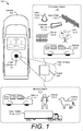
- FIG. 1 is an illustration of an example environment 100 in which techniques using, and an apparatus including, a lidar system 102 with a low-cost readout module may be embodied.
- the lidar system 102 is mounted to, or integrated within, a vehicle 104.
- the lidar system 102 is capable of detecting one or more objects 108 that are within proximity to the vehicle 104.
- the vehicle 104 can represent other types of motorized vehicles (e.g., a motorcycle, a bus, a tractor, a semi-trailer truck, or construction equipment), types of non-motorized vehicles (e.g., a bicycle), types of railed vehicles (e.g., a train or a trolley car), watercraft (e.g., a boat or a ship), aircraft (e.g., an airplane or a helicopter), or spacecraft (e.g., satellite).
- the vehicle 104 can tow, or include, a trailer or other attachments.
- the lidar system 102 can be mounted to any type of moving platform, including moving machinery or robotic equipment.
- the lidar system 102 is mounted on top of the vehicle 104 and provides a field of view 106 illuminating an object 108.
- the lidar system 102 can be mounted to a front side, a backside, a left side, or a right side of the vehicle 104.
- the vehicle 104 includes multiple lidar systems 102, such as a first rear-mounted lidar system 102 positioned near a left side of the vehicle 104 and a second rear-mounted lidar system 102 positioned near a right side of the vehicle 104.
- locations of the one or more lidar systems 102 can be designed to provide a particular field of view 106 that encompasses a region of interest in which the object 108 may be present.
- Example fields of view 106 include a 360-degree field of view, one or more 180-degree fields of view, one or more 90-degree fields of view, and so forth, which can overlap (e.g., four 120-degree fields of view).
- the object 108 is composed of one or more materials that reflect lidar signals.
- the object 108 can represent a target of interest or clutter.
- the object 108 is a moving object 110, such as another vehicle 110-1, a semi-trailer truck 110-2, a human 110-3, or an animal 110-4.
- the object 108 represents a stationary object 112, such as traffic cone 112-1, a concrete barrier 112-1, a guard rail 112-3, a fence 112-4, a tree 112-5, a parked vehicle 112-6, or a reflector on the road.
- the stationary object 112 may even comprise a road barrier, which can be continuous or discontinuous along a portion of the road.
- the lidar system 102 represents a time-of-flight lidar system, which transmits and receives lidar signals comprised of pulses.
- the lidar system 102 measures a distance to the object 108 based on a time it takes for the pulses to travel from the lidar system 102 to the object 108, and from the object 108 back to the lidar system 102.
- the lidar system 102 can also measure reflective properties of the object 108 based on the intensity of the received pulses.
- the intensity information can be used to determine the type of object 108 detected or classify the object 108.
- the lidar system 102 can determine whether the object 108 is a vehicle 112-6, a lane marker, a surface of a road, or a human 110-3.
- the intensity information also enables the lidar system 102 to determine a property of the object 108, such as a material composition of the object 108.
- the lidar system 102 and the vehicle 104 are further described with respect to FIG. 2 .
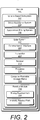
- FIG. 2 illustrates the lidar system 102 as part of the vehicle 104.
- the vehicle 104 includes at least one vehicle-based subsystem 202, such as a driver-assistance system 204 and/or an autonomous-driving system 206.
- the vehicle-based subsystem 202 uses lidar data provided by the lidar system 102 to perform a function.
- the driver-assistance system 204 provides blind-spot monitoring and generates an alert that indicates a potential collision with an object 108 that is detected by the lidar system 102.
- the lidar data from the lidar system 102 is used to indicate when it is safe or unsafe to change lanes.
- the autonomous-driving system 206 may move the vehicle 104 to a particular location while avoiding collisions with other objects 108 detected by the lidar system 102.
- the lidar data provided by the lidar system 102 can provide information about the location and movement of the other objects 108 to enable the autonomous-driving system 206 to perform emergency braking, perform a lane change, or adjust the vehicle 104's speed.
- the lidar system 102 includes a communication interface 208 to transmit the lidar data to the vehicle-based subsystem 202 or to another component of the vehicle 104 over a communication bus of the vehicle 104, for example, when the individual components shown in the lidar system 102 are integrated within the vehicle 104.
- the lidar data provided by the communication interface 208 is in a format usable by the vehicle-based subsystem 202.
- the communication interface 208 may provide information to the lidar system 102, such as the speed of the vehicle 104 or whether a turning blinker is on or off. The lidar system 102 can use this information to appropriately configure itself. For example, the lidar system 102 can adjust its frame rate or scanning speed based on the speed of the vehicle 104.
- the lidar system 102 can dynamically adjust the field of view 106 based on whether a right-turning blinker or a left-turning blinker is on.
- Other types of adjustments can include parameters of threshold detectors or analog-to-digital converters within the lidar system 102, such as those within a readout-module 218, which is further described below.
- the lidar system 102 also includes a transmitter 210 to transmit lidar signals and a receiver 212 to receive reflected versions of these lidar signals.
- the transmitter 210 includes optical elements for emitting lidar signals and related components for directing the lidar signals.
- the transmitter 210 can form beams that are steered or un-steered, and wide or narrow. The steering and shaping can be achieved through analog beamforming or digital beamforming.
- the receiver 212 includes optical elements for detecting the reflected lidar signals, such as photodetectors. In some implementations, the photodetector is implemented as a silicon photomultiplier (SiPM).
- the lidar system 102 also includes one or more processors 214 and computer-readable storage media (CRM) 216.
- the processor 214 can be implemented as a microprocessor or a system-on-chip.
- the processor 214 executes instructions that are stored within the computer-readable storage media.
- the processor 214 can determine a location of the object 108 (of FIG. 1 ) relative to the lidar system 102 (e.g., determine a slant range, azimuth, and elevation to the object 108), determine the material composition of the object 108, or classify the object 108.
- the processor 214 detects the object 108 based on information provided by the receiver 212.
- the processor 214 also generates the lidar data for the vehicle-based subsystem 202.
- the lidar system 102 also includes a readout module 218.
- the readout module 218 provides an interface between the receiver 212 and the processor 214.
- the readout module 218 is incorporated within the receiver 212 and implemented on the same integrated circuit.
- the readout module 218 is separate from the receiver 212 and implemented on a different integrated circuit (or multiple integrated circuits).
- a portion of the readout module 218 can also be implemented by the processor 214, as further described below.
- the readout module 218 extracts information from analog signals provided by the receiver 212 and generates digital information for the processor 214. To reduce the cost of the readout module 218, the readout module 218 separately determines time-sensitive information and non-time-sensitive information for each receive channel within the receiver 212.
- the readout module 218 includes at least one timing readout path 220 and at least one intensity readout path 222, which are further described with respect to FIGs. 3-1 to 3-3 .
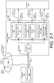
- FIG. 3-1 illustrates an example readout module 218 connected between the receiver 212 and the processor 214.
- the readout module 218 includes the timing readout path 220 and the intensity readout path 222 of FIG. 2 .
- the readout module 218 also includes at least one input node 302, at least one output node 304, and at least another output node 306.
- the input node 302 is coupled to the receiver 212, and the output nodes 304 and 306 are coupled to the processor 214.
- the receiver 212 includes at least one receive channel 308, which is coupled to the input node 302.
- the timing readout path 220 is coupled between the input node 302 and the output node 304.
- the intensity readout path 222 is coupled between the input node 302 and the output node 306. In general, both the timing readout path 220 and the intensity readout path 222 are coupled to the same input node 302 and therefore operate on similar input data.
- the timing readout path 220 generates time-sensitive information based on the input data, and the intensity readout path 222 generates non-time-sensitive information based on the input data. In some cases, the timing readout path 220 analyzes information within the input data that varies at a faster rate than the information analyzed by the intensity readout path 222.
- the readout module 218 includes an isolation circuit 310.
- the isolation circuit 310 isolates the timing readout path 220 and the intensity readout path 222 from the receive channel 308.
- the isolation circuit 310 can be implemented using a buffer or a current mirror.
- the isolation circuit 310 additionally provides current-to-voltage conversion and/or amplification.
- the isolation circuit 310 can include a current-to-voltage converter, which generates a voltage based on an input current provided at the input node 302.
- the current-to-voltage converter can be implemented using a transimpedance amplifier (TIA), for instance.
- the isolation circuit 310 can be implemented within the receiver 212 (e.g., between the receive channel 308 and the input node 302).
- the timing readout path 220 includes at least one threshold-triggered timing circuit 312, which can be implemented within a system-on-chip (SoC).
- the threshold-triggered timing circuit 312 determines times associated with a voltage or current being greater than, equal to, or less than a threshold.
- the threshold-triggered timing circuit 312 can include at least one threshold detector and at least one time-capture circuit, such as a time-to-digital converter. An example implementation of the threshold-triggered timing circuit 312 with a time-to-digital converter is further described with respect to FIG. 3-2 .
- a threshold of the threshold-triggered timing circuit 312 can be pre-programmed or controlled by the processor 214, as further described below. In some implementations, at least a portion of the threshold-triggered timing circuit 312 is implemented by the processor 214.
- the intensity readout path 222 includes at least one hold-and-sample circuit 314.
- the hold-and-sample circuit 314 processes and holds an input signal for a specified duration and samples the input signal.
- the hold duration and sampling rate of the hold-and-sample circuit 314 can be pre-programmed or controlled by the processor 214, as further described below.
- the hold-and-sample circuit 314 can also perform analog-to-digital conversion. An example implementation of the hold-and-sample circuit 314 with a hold circuit and an analog-to-digital converter is further described with respect to FIG. 3-3 .
- the receive channel 308 of the receiver 212 generates pulse data 316.
- the pulse data 316 represents a response of the lidar system 102 to a lidar receive signal 318.
- the lidar receive signal 318 can represent a version of a lidar transmit signal that is transmitted by the transmitter 210 (of FIG. 3 ) and reflected by the object 108 (of FIG. 1 ).
- the lidar receive signal 318 includes multiple pulses 320, such as pulses 320-1 to 320-C, where "C" represents a positive integer.
- the quantity of pulses 320 within the lidar receive signal 318 can be on the order of hundreds or thousands.
- a duration (e.g., pulse width) of each pulse 320 can be on the order of nanoseconds, such as between one and twenty nanoseconds.
- An interval between each pulse 320 can be on the order of microseconds, such as between one and five microseconds, for example.
- the pulse data 316 is a time-domain analog signal that includes timing information and intensity information of the pulses 320-1 to 320-C.
- the readout module 218 accepts the pulse data 316, which can be represented by an input voltage or an input current.
- the readout module 218 provides the pulse data 316 to both the timing readout path 220 and the intensity readout path 222. Both the timing readout path 220 and the intensity readout path 222 accept and process the pulse data 316.
- the timing readout path 220 generates timing data 322 based on the pulse data 316.
- the timing data 322 can represent times associated with the pulses 320-1 to 320-C, such as times associated with rising edges or falling edges of the pulses 320-1 to 320-C.
- the threshold-triggered timing circuit 312 determines times associated with a voltage or current of the pulse data 316 being greater than, equal to, or less than a threshold.
- the intensity readout path 222 generates intensity data 324 based on the pulse data 316.
- the intensity data 324 represents amounts of energy associated with the pulses 320-1 to 320-C (e.g., represents the number of photons associated with each optical pulse that is received by the receiver 212).
- the hold-and-sample circuit 314 extends durations for which intensity information of the pulses 320-1 to 320-C is available and samples the pulses 320-1 to 320-C.
- the intensity data 324 is composed of these samples.
- the processor 214 analyzes the timing data 322 and/or the intensity data 324 associated with the pulses 320-1 to 320-C to detect the object 108.
- the processor 214 can also use the timing data 322 to measure a distance between the lidar system 102 and the object 108. Additionally, the processor 214 can use the intensity data 324-1 to 324-M to determine a material composition of the object 108 and/or classify the object 108. Information regarding the object 108's distance and classification can be provided as lidar data to the vehicle-based subsystems 202 of FIG. 2 .
- the processor 214 or a controller controls operations of one or more components within the readout module 218.
- the processor 214 can generate a control signal 326 and provide the control signal 326 to the readout module 218.
- the readout module 218 can set the threshold of the threshold-triggered timing circuit 312, set a duration that the hold-and-sample circuit 314 holds the pulse data 316, or set a sampling rate of the hold-and-sample circuit 314 based on the control signal 326. In this way, parameters of the readout module 218 can be dynamically adjusted by the processor 214 depending on the type of lidar signal transmitted or an operational mode of the lidar system 102.
- the readout module 218 can optionally include at least one pulse-shape readout path 348 and at least one output node 350.
- the pulse-shape readout path 348 is coupled between the input node 302 and the output node 350, and includes at least one analog-to-digital converter 352.
- the pulse-shape readout path 348 can also include a low-pass filter, which is coupled between the input node 302 and the analog-to-digital converter 352.
- the pulse-shape readout path 348 uses the analog-to-digital converter 352 to generate pulse-shape data 354 based on the pulse data 316.
- the pulse-shape data 354 can include timing information and intensity information, which characterizes a shape of the pulse 320.
- a sampling rate of the analog-to-digital converter 352 is sufficient to capture an approximate shape of the pulse 320.
- the analog-to-digital converter 352 can be implemented using a low-performance analog-to-digital converter.
- the processor 214 can rely on the timing data 322 instead of the pulse-shape data 354 to measure a distance to the object 108.
- the timing data 322 is not available for the pulse 320. This can occur, for instance, if the amplitude of the pulse 320 is below a threshold evaluated by the threshold-triggered timing circuit 312.
- the width of the pulse 320 can be sufficiently wide to enable the sampling rate of the analog-to-digital converter 352 to collect multiple samples and generate the pulse-shape data 354.
- the sampling rate of the analog-to-digital converter 352 enables at least one sample to be collected during a rising edge of the pulse 320, at least one sample to be collected during a falling edge of the pulse 320, and at least one sample collected between these samples.
- the processor 214 can analyze the pulse-shape data 354 to detect the object 108 and measure the distance to the object 108 for situations in which the timing data 322 is not available.
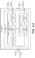
- FIG. 3-2 illustrates an example timing readout path 220 of the readout module 218.
- the timing readout path 220 includes threshold-triggered timing circuits 312-1 to 312-N and output nodes 304-1to 304-N, where "N" represents a positive integer.
- the threshold-triggered timing circuit 312-1 is coupled between the input node 302 and the output node 304-1.
- the threshold-triggered timing circuit 312-N is coupled between the input node 302 and the output node 304-N.
- the isolation circuit 310 of FIG. 3 can be coupled between the input node 302 and the threshold-triggered timing circuits 312-1 to 312-N.
- the threshold-triggered timing circuits 312-1 includes a time-to-digital converter 328 and a threshold detector 330. Although the threshold detector 330 and the time-to-digital converter 328 are shown to be separate components, some implementations can integrate the threshold detector 330 and the time-to-digital converter 328 together. In other implementations, the time-to-digital converter 328 can be implemented by the processor 214 (of FIG. 3-1 ). The time-to-digital converter 328 is coupled between the input node 302 and the output node 304-1. The threshold detector 330 is coupled between the input node 302 and the time-to-digital converter 328. The time-to-digital converter 328 generates digital timing information based on a trigger generated by the threshold detector 330.
- the threshold-triggered timing circuit 312-1 optionally includes a high-pass filter 332. The high-pass filter 332 can be coupled between the input node 302 and the threshold detector 330.
- the threshold-triggered timing circuit 312-1 of FIG. 3-2 can implement the threshold-triggered timing circuit 312 of FIG. 3-1 .
- Other ones of the threshold-triggered timing circuit 312-2 to 312-N can have one or more components that are similar to the components within the threshold-triggered timing circuit 312-1.
- the threshold-triggered timing circuit 312-N includes a threshold detector 334, which is coupled between the input node 302 and the output node 304-N. If the threshold-triggered timing circuit 312-1 includes the high-pass filter 332, the threshold detector 334 can be coupled to either an input of the high-pass filter 332 (as shown in FIG. 3-2 ) or an output of the high-pass filter 332 (not shown in FIG. 3-2 ).
- the threshold-triggered timing circuit 312-N can optionally include a time-to-digital converter 336. The time-to-digital converter 336 is coupled between the threshold detector 334 and the output node 304-N.
- other ones of the threshold-triggered timing circuit 312-2 to 312-(N-1) can include another threshold detector, another time-to-digital converter, another high-pass filter, or some combination thereof.
- the high-pass filter 332 attenuates low-frequency noise within the pulse data 316 to improve a signal-to-noise ratio of the pulse data 316.
- the threshold detector 330 monitors a voltage or a current associated with the filtered pulse data 316.
- the threshold detector 330 compares the monitored voltage or current to a threshold and triggers the time-to-digital converter 328 responsive to a condition associated with the comparison being satisfied (e.g., based on the monitored voltage or current being greater than, equal to, or less than the threshold).
- a value of the threshold can be set based on a noise floor of the receiver 212, for instance.
- the voltage threshold can be approximately 0.1 volts, for instance.
- the time-to-digital converter 328 generates timing data 322-1 based on the trigger provided by the threshold detector 330.
- the time-to-digital converter 328 identifies a time that the filtered pulse data 316 satisfied the condition evaluated by the threshold detector 330. Depending on the condition, this time can be associated with a rising edge or a falling edge of a pulse 320 within the pulse data 316.
- the time-to-digital converter 328 generates the timing data 322-1, which indicates times associated with rising edges of the pulses 320-1 to 320-C within the pulse data 316 (e.g., times at which voltages of the pulses 320-1 to 320-C are greater than or equal to the threshold).
- the threshold-triggered timing circuit 312-N performs similar operations as described above using the threshold detector 334 and/or the time-to-digital converter 336.
- the threshold detector 334 also monitors the voltage or current associated with the pulse data 316.
- the threshold detector 334 compares the monitored voltage or current to another threshold, which differs from the threshold evaluated by the threshold detector 330.
- the threshold used by the threshold detector 334 can be greater than the threshold used by the threshold detector 330. This threshold can be between approximately 0.2 volts and 0.5 volts, for instance.
- the threshold-triggered timing circuit 312-N uses the threshold detector 334, the threshold-triggered timing circuit 312-N generates timing data 322-N.
- the timing data 322-N generated using the threshold detector 334 can be used to verify that the time measured by the time-to-digital converter 328 is associated with one of the pulses 320 instead of noise.
- the processor 214 can reference the timing data 322-N to analyze portions of the timing data 322-1 that are likely to be associated with one of the pulses 320 and filter (e.g., discard) portions of the timing data 322-1 that are likely to be associated with noise.
- the threshold-triggered timing circuit 312-N includes the time-to-digital converter 336.
- the timing data 322-N can include times at which the condition monitored by the threshold detector 334 is satisfied.
- the timing data 322-N can include a time at which a rising edge of a pulse 320 reaches another a voltage level.
- the processor 214 can analyze the timing data 322-1 and the timing data 322-N to estimate a shape of the pulse 320.
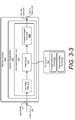
- FIG. 3-3 illustrates an example intensity readout path 222 of the readout module 218.
- the intensity readout path 222 includes the hold-and-sample circuit 314.
- the hold-and-sample circuit 314 includes an analog-to-digital converter 338 and a hold circuit 340.
- the analog-to-digital converter 338 is coupled between the input node 302 and the output node 306.
- the hold circuit 340 is coupled between the input node 302 and the analog-to-digital converter 338.
- the hold circuit 340 enables the analog-to-digital converter 338 to operate at a slow sampling frequency, as further described below.
- the hold circuit 340 can be implemented as an integrate-and-hold circuit 342 or a peak-and-hold circuit 344.
- the integrate-and-hold circuit 342 measures an amount of charge within the pulse 320 (e.g., measures an amount of current or voltage over time) and generates a voltage, which represents the intensity of the pulse 320.
- the peak-and-hold circuit 344 measures a peak amplitude of a current or voltage across the pulse 320 and generates a voltage, which represents the intensity of the pulse 320.
- the intensity data 340 can include the amount of charge measured by the integrate-and-hold circuit 342 or the peak amplitude measured by the peak-and-hold circuit 344.
- the intensity data 340 can represent a scaled quantity of photons that are received within an optical pulse of the lidar receive signal 318.
- the hold-and-sample circuit 314 can optionally include a low-pass filter 346.
- the low-pass filter 346 can be coupled between the input node 302 and the hold circuit 340, or coupled between the hold circuit 340 and the analog-to-digital converter 338.
- the low-pass filter 346 can be used to attenuate high-frequency noise within the pulse 320. By attenuating the noise, the low-pass filter 346 improves a measurement accuracy of the hold circuit 340.
- the hold circuit 340 generates an output voltage that represents an amount of energy (e.g., an amount of charge measured by the integrate-and hold circuit 342 or a peak amplitude measured by the peak-and-hold circuit 344) associated with the pulse 320 and maintains the output voltage for a duration that is longer than a duration of the pulse 320.
- the intensity readout path 222 extends a duration of the pulse data 316, which enables the analog-to-digital converter 338 to sample data associated with each pulse 320 over a time period that is longer than a duration of the pulse 320.
- the duration that the output voltage is held can be limited based on the time interval between the transmitted pulses or a target resolution for distinguishing between different objects 108.
- the processor 214 sets the duration using the control signal 326 (of FIG. 3-1 ). This can include setting a time that the hold circuit 340 resets.
- the analog-to-digital converter 338 collects one or more samples of the output voltage and generates the intensity data 324, which indicates an amount of the energy associated with the pulse 320.
- the analog-to-digital converter 338 can operate at a slower sampling rate relative to other high-performance analog-to-digital converters that generate both timing data and intensity data. This enables the analog-to-digital converter 338 to be implemented using a low-performance analog-to-digital converter.
- the processor 214 sets the sampling rate of the analog-to-digital converter 338 using the control signal 326 (of FIG. 3-1 ).
- Example implementations of the readout module 218 for supporting multiple receive channels within the receiver 212 are further described with respect to FIGs. 4 and 5 .
- FIG. 4 illustrates an example readout module 218 for supporting multiple receive channels 308-1 to 308-M of the receiver 212.
- the variable "M" represents a positive integer, which can be equal to two, three, four, six, twelve, twenty-four, and so forth.
- the readout module 218 includes input nodes 302-1 to 302-M, timing readout paths 220-1 to 220-M, intensity readout paths 222-1 to 222-M, output nodes 304-1 to 304-M, and output nodes 306-1 to 306-M.
- the readout module 218 is coupled between the receiver 212 and the processor 214.
- the input nodes 302-1 to 302-M are respectively coupled to the receive channels 308-1 to 308-M.
- the processor 214 is coupled to the output nodes 304-1 to 304-M and 306-1 to 306-M.
- the timing readout paths 220-1 to 220-M each include at least one threshold-triggered timing circuit 312.
- the time-to-digital converters 328-1 to 328-M and the threshold detectors 330-1 to 330-M shown in FIG. 4 represent respective threshold-triggered timing circuits 312 of the timing readout paths 220-1 to 220-M.
- the timing readout paths 220-1 to 220-M can include additional threshold-triggered timing circuits 312, such as the threshold-triggered timing circuit 312-N of FIG. 3-2 .
- the intensity readout paths 222-1 to 222-M each include at least one hold-and-sample circuit 314.
- the analog-to-digital converters 338-1 to 338-M and the hold circuits 340-1 to 340-M shown in FIG. 4 represent respective hold-and-sample circuits 314 of the intensity readout paths 222-1 to 222-M.
- other components of the timing readout paths 220-1 to 220-M and the intensity readout paths 222-1 to 222-M are not shown. It is to be understood, however, that any of the components described above with respect to FIGs. 3-2 and 3-3 may also be present within the example implementation shown in FIG. 4 .
- the receive channels 308-1 to 308-M respectively provide pulse data 316-1 to 316-M to the input nodes 302-1 to 302-M.
- the timing readout paths 220-1 to 220-M respectively process the pulse data 316-1 to 316-M to generate timing data 322-1 to 322-M.
- the intensity readout paths 222-1 to 222-M respectively process the pulse data 316-1 to 316-M to generate intensity data 324-1 to 324-M.
- the intensity readout paths 222-1 to 222-M are independent and separate from each other. Consequently, the quantity of analog-to-digital converters 338-1 to 338-M is equal to the quantity of receive channels 308-1 to 308-M. Alternatively, the quantity of analog-to-digital converters 338 can be less than the quantity of receive channels 308, as described below with respect to FIG. 5 .
- FIG. 5 illustrates another example readout module 218 for supporting the multiple receive channels 308-1 to 308-M.
- two or more of the intensity readout paths 222-1 to 222-M share the analog-to-digital converter 338. Consequently, the readout module 218 of FIG. 5 has a fewer quantity of analog-to-digital converters 338 relative to the readout module 218 of FIG. 4 . This can enable a size of the readout module 218 of FIG. 5 to be smaller than the readout module 218 of FIG. 4 . Because the analog-to-digital converter 338 is shared across multiple intensity readout paths 222-1 to 222-M, a sampling rate of the analog-to-digital converter 338 of FIG.
- the analog-to-digital converter 338 of FIG. 5 may be faster than a sampling rate of the analog-to-digital converters 338 of FIG. 4 . Consequently, the analog-to-digital converter 338 of FIG. 5 may be more expensive than one of the analog-to-digital converters 338 of FIG. 4 .
- analog-to-digital converter 338 in FIG. 5 is shown to be shared between all of the intensity readout paths 222-1 to 222-M in FIG. 5
- alternative implementations can share the analog-to-digital converter 338 across a subset of the intensity readout paths 222-1 to 222-M.
- the readout module 218 includes multiple analog-to-digital converters 338.
- two or more intensity readout paths 222-1 to 222-M share the analog-to-digital converter 338 while the remaining intensity readout paths 222-1 to 222-M respectively use the remaining analog-to-digital converters 338.
- the intensity readout paths 222-1 to 222-M are divided into different groups, which include two or more intensity readout paths 222-1 to 222-M.
- the quantities of intensity readout paths 222 within the groups can be similar or different.
- the different groups respectively share different analog-to-digital converters 338.
- the receiver 212 includes twelve receive channels 308 (e.g., "M" equals twelve), and the readout module 218 includes four analog-to-digital converters 338.
- the intensity readout paths 222 are divided into groups of three, which utilize different analog-to-digital converters 338.
- Each group of intensity readout paths 222 that share an analog-to-digital converter 338 also jointly include a selection circuit 502.
- the selection circuit 502 is coupled between the shared analog-to-digital converter 338 and the associated input nodes 302 of the intensity readout paths 222.
- the selection circuit 502 can be coupled between respective hold circuits 340 of the intensity readout paths 222 and the analog-to-digital converter 338.
- the selection circuit 502 can be implemented using one or more switches or a multiplexer.
- the processor 214 or a controller can control an order and duration in which the selection circuit 502 connects the input nodes 302-1 to 302-M to the analog-to-digital converter 338.
- the processor 214 can control the selection circuit 502 using the control signal 326 of FIG. 3 --.
- timing readout paths 220-1 to 220-M and the intensity readout paths 222-1 to 222-M are not shown in FIG. 5 . It is to be understood, however, that any of the components described above with respect to FIGs. 3-2 and 3-3 may also be present within the example implementation shown in FIG. 5 .
- the receive channels 308-1 to 308-M respectively provide pulse data 316-1 to 316-M to the input nodes 302-1 to 302-M.
- the readout module 218 passes the pulse data 316-1 to 316-M to the timing readout paths 220-1 to 220-M and the intensity readout paths 222-1 to 222-M.
- the timing readout paths 220-1 to 220-M of FIG. 5 perform similar operations as the timing readout paths 220-1 to 220-M of FIG. 4 .
- the selection circuit 502 selectively connects the hold circuits 340-1 to 340-M to the analog-to-digital converter 338.
- the selection circuit 502 can repeatedly cycle through connecting each of the 340-1 to 340-M to the analog-to-digital converter 338.
- the selection circuit 502 can enable a single sample or multiple samples to be collected from the hold circuit 340-1 prior to connecting the next hold circuit 340-2 to 340-M. In this way samples from different receive channels 308-1 to 308-M can be grouped together by pulse, interleaved, or some combination thereof.
- the duration of the pulses 320, the time period between the pulses 320, and a target resolution for distinguishing between different objects 108, the hold circuit 340, the selection circuit 502, and the analog-to-digital converter 338 can be designed to enable multiple samples to be collected for each pulse data 316-1 to 316-M.
- the analog-to-digital converter 338 generates intensity data 324-1 to 324-M, which is provided to the processor 214.
- the intensity data 324-1 to 324-M is provided by a single signal, which represents a multiplexed version of the intensity data 324-1 to 324-M.
- the processor 214 can include a demultiplexing circuit, which performs a reciprocal operation that extracts the intensity data 324-1 to 324-M from the multiplexed signal at the output node 306. This enables the processor 214 to recover information from each individual receive channel 308-1 to 308-M.
- FIG. 6 depicts an example method 600 for performing multiple readouts of a receive channel within a lidar system 102.
- Method 600 is shown as sets of operations (or acts) performed but not necessarily limited to the order or combinations in which the operations are shown herein. Further, any of one or more of the operations may be repeated, combined, or reorganized to provide other methods.
- a lidar signal that is reflected by an object is received.
- the receiver 212 of the lidar system 102 receives the lidar receive signal 318 (of FIG. 3-1 ).
- pulse data is generated using a receive channel of a lidar system.
- the pulse data is based on the lidar signal.
- the receive channel 308 of the receiver 212 generates the pulse data 316 based on the lidar receive signal 318, as shown in FIG. 3-1 .
- the pulse data is passed to a timing readout path of the lidar system and an intensity readout path of the lidar system.
- the readout module 218 passes the pulse data 316 to the timing readout path 220 and the intensity readout path 222, as shown in FIG. 3-1 .
- the pulse data 316 can be represented by a voltage or a current.
- timing data is generated using the timing readout path.
- the timing data identifies a time associated with a rising edge of a pulse within the pulse data.
- the timing readout path 220 generates the timing data 322, which identifies a time associated with a rising edge of a pulse 320 within the pulse data 316.
- the timing readout path 220 includes at least one threshold-triggered timing circuit 312 with a time-to-digital converter 328 and a threshold detector 330.
- the threshold-triggered timing circuit 312 can generate a timestamp that represents a time at which a rising edge of the pulse 320 is greater than or equal to a threshold.
- the timing readout path 220 includes another threshold-triggered timing circuit 312 with at least another threshold detector 334.
- the timing readout path 220 can utilize the threshold-triggered timing circuit 312 to indicate whether or not the timing data 322 is likely associated with the pulse 320 or noise.
- intensity data is generated using the intensity readout path.
- the intensity data indicates an amount of energy within the pulse.
- the intensity readout path 222 generates intensity data 324, which indicates an amount of energy within the pulse 320.
- the intensity data 324 includes a measurement amount of charge associated with the pulse 320 or a measured amount of peak current associated with the pulse 320.
- the object is detected based on the timing data and the intensity data.
- the processor 214 detects the object 108 based on the timing data 322 and the intensity data 324.
- the processor 214 can also use the timing data 322 to measure a distance to the object 108. Additionally or alternatively, the processor 214 can identify a material composition of the object 108 or classify the object 108 based on the intensity data 324.
Landscapes
- Engineering & Computer Science (AREA)
- Physics & Mathematics (AREA)
- Computer Networks & Wireless Communication (AREA)
- General Physics & Mathematics (AREA)
- Radar, Positioning & Navigation (AREA)
- Remote Sensing (AREA)
- Electromagnetism (AREA)
- Optical Radar Systems And Details Thereof (AREA)
- Radar Systems Or Details Thereof (AREA)
Abstract
Description
- Automotive lidar systems determine speed and distance of stationary and moving objects (e.g., other vehicles, pedestrians, obstacles, other objects of interest). A lidar system emits signals having shorter wavelengths (e.g., one to ten micrometers) than a radar system and therefore has improved spatial resolution for detecting small objects.
- For high frame-rate and long-range applications, it is desirable to increase the quantity of receive channels within a lidar system. In particular, a larger quantity of receive channels can improve the angular resolution of the lidar system. Increasing the quantity of receive channels, however, can increase the cost and complexity of the lidar system's readout module, which generates digital information based on signals provided by the receive channels.
- Techniques and apparatuses are described that implement a low-cost readout module for a lidar system. In an example time-of-flight (ToF) lidar system, the low-cost readout module includes at least two readout paths, which are coupled to a receive channel of the lidar system. The two readout paths include a timing readout path and an intensity readout path. The timing readout path includes at least one threshold-triggered timing circuit, which generates time-sensitive information, such as timing data. The timing data can be used to detect an object and determine a distance to the object. In an example implementation, the threshold-triggered timing circuit includes a time-to-digital converter to identify a time associated with a rising edge of a pulse. The time-to-digital converter can be less expensive than an analog-to-digital converter. In some implementations, the timing readout path includes another threshold-triggered timing circuit to confirm that the time identified by the time-to-digital converter is associated with a pulse instead of noise.
- The intensity readout path generates non-time-sensitive information, such as intensity data, which can be used to detect and/or classify the object. The intensity readout path includes a hold-and-sample circuit. In an example implementation, the hold-and-sample circuit includes a hold circuit and an analog-to-digital converter. By including the hold circuit, a low-performance analog-to-digital converter can sample an output of the hold circuit. The low-performance analog-to-digital converter can operate at a slower sampling rate and have a smaller bandwidth relative to other high-performance analog-to-digital converters that can provide both time-sensitive information and non-time-sensitive information. In some implementations, a low-performance analog-to-digital converter can be shared by multiple intensity readout paths to reduce size or complexity of the readout module. By utilizing a threshold-triggered timing circuit to provide time-sensitive data and a hold-and-sample circuit to provide non-time-sensitive information, the readout module can have a lower cost than other readout modules that utilize a high-performance analog-to-digital converter for each receive channel.
- Aspects described below include an apparatus comprising a lidar system. The lidar system comprises a receiver and a readout module. The receiver comprises a receive channel. The readout module is coupled to the receiver and comprises a first node coupled to the receive channel, a second node, and a third node. The readout module also comprises a timing readout path and an intensity readout path. The timing readout path is coupled between the first node and the second node. The timing readout path comprises a time-to-digital converter. The intensity readout path is coupled between the first node and the third node. The intensity readout path comprises an analog-to-digital converter.
- Aspects described below also include a method performed by a lidar system. The method includes receiving a lidar signal that is reflected by an object. The method also includes generating, using a receive channel of the lidar system, pulse data based on the lidar signal. Additionally, the method includes passing the pulse data to a timing readout path of the lidar system and an intensity readout path of the lidar system. Using the timing readout path, the method includes generating timing data that identifies a time associated with a rising edge of a pulse within the pulse data. Using the intensity readout path, the method includes generating intensity data that indicates an amount of energy associated with the pulse. The method further includes detecting the object based on the timing data and the intensity data.
- Aspects described below also include a lidar system comprising reception means for generating pulse data based on a lidar signal that is reflected by an object. The lidar system also includes threshold-triggered means for generating timing data based on the pulse data. The timing data identifies times associated with rising edges of pulses within the pulse data. The lidar system additionally includes hold-and-sample means for generating intensity data by extending durations of the pulses within the pulse data and sampling the pulses. The intensity data indicates amounts of energy associated with the pulses. Both the threshold-triggered means and the hold-and-sample means are coupled to the reception means.
- This summary is provided to introduce simplified concepts for implementing a low-cost readout module for a lidar system, which are further described below in the Detailed Description and Drawings. For ease of description, the disclosure focuses on automotive lidar systems; however, the techniques are not limited to automobiles. The techniques also apply to lidars of other types of vehicles, systems, and moving platforms. This summary is not intended to identify essential features of the claimed subject matter, nor is it intended for use in determining the scope of the claimed subject matter.
- The details of one or more aspects of implementing a low-cost readout module for a lidar system are described in this document with reference to the following figures. The same numbers are used throughout the drawings to reference like features and components:
-
FIG. 1 illustrates an example environment in which a lidar system with a low-cost readout module can be implemented. -
FIG. 2 illustrates an example implementation of a lidar system as part of a vehicle. -
FIG. 3-1 illustrates an example readout module connected between a receiver and a processor of a lidar system. -
FIG. 3-2 illustrates an example timing readout path of a readout module. -
FIG. 3-3 illustrates an example intensity readout path of a readout module. -
FIG. 4 illustrates an example readout module for supporting multiple receive channels. -
FIG. 5 illustrates another example readout module for supporting multiple receive channels. -
FIG. 6 illustrates an example method performed by a lidar system with a low-cost readout module. - Automotive lidar systems are becoming one of the vital sensing technologies on which some vehicle-based subsystems rely for acquiring critical information about an environment surrounding a vehicle. For high frame-rate and long-range applications, it is desirable to increase the quantity of receive channels within a lidar system. A larger quantity of receive channels, for instance, can improve the angular resolution of the lidar system. Increasing the quantity of receive channels, however, can increase the cost of a readout module within the lidar system.
- Some readout modules include an analog-to-digital converter for each receive channel to extract both timing information and intensity information. However, to generate accurate timing information and support high throughput, the analog-to-digital converters are designed to have a high-sampling rate and large bandwidth. As such, the analog-to-digital converters can be expensive. Furthermore, because the readout module uses an analog-to-digital converter for each receive channel, increasing the quantity of receive channels within the lidar system increases the quantity of analog-to-digital converts within the readout module, and therefore increases the cost of the lidar system. With fewer receive channels, the lidar system may not be able to achieve a target angular resolution.
- Other readout modules include a time-to-digital converter for each receive channel to extract timing information. Although the time-to-digital converter is less expensive than a high-performance analog-to-digital converter, the time-to-digital converter is unable to extract intensity information. Without the intensity information, the lidar system is unable to determine reflective properties of the object, which can make it challenging to detect or classify the object.
- To address this issue, this document describes techniques and systems that implement a low-cost readout module for a lidar system. In an example time-of-flight (ToF) lidar system, the low-cost readout module includes at least two readout paths, which are coupled to a receive channel of the lidar system. The two readout paths include a timing readout path and an intensity readout path. The timing readout path includes at least one threshold-triggered timing circuit, which generates time-sensitive information, such as timing data. The timing data can be used to detect an object and determine a distance to the object. In an example implementation, the threshold-triggered timing circuit includes a time-to-digital converter to identify a time associated with a rising edge of a pulse. The time-to-digital converter can be less expensive than an analog-to-digital converter. In some implementations, the timing readout path includes another threshold-triggered timing circuit to confirm that the time identified by time-to-digital converter is associated with a pulse instead of noise.
- The intensity readout path generates non-time-sensitive information, such as intensity data, which can be used to detect and/or classify the object. The intensity readout path includes a hold-and-sample circuit. In an example implementation, the hold-and sample circuit includes a hold circuit and an analog-to-digital converter. By including the hold circuit, a low-performance analog-to-digital converter can sample an output of the hold circuit. The low-performance analog-to-digital converter can operate at a slower sampling rate and have a smaller bandwidth relative to other high-performance analog-to-digital converters that can provide both time-sensitive information and non-time-sensitive information. In some implementations, a low-performance analog-to-digital converter can be shared by multiple intensity readout paths to reduce size or complexity of the readout module. By utilizing a threshold-triggered timing circuit to provide time-sensitive data and a hold-and-sample circuit to provide non-time-sensitive information, the readout module can have a lower cost than other readout modules that utilize a high-performance analog-to-digital converter for each receive channel.
-
FIG. 1 is an illustration of anexample environment 100 in which techniques using, and an apparatus including, alidar system 102 with a low-cost readout module may be embodied. In the depictedenvironment 100, thelidar system 102 is mounted to, or integrated within, avehicle 104. Thelidar system 102 is capable of detecting one ormore objects 108 that are within proximity to thevehicle 104. Although illustrated as a car, thevehicle 104 can represent other types of motorized vehicles (e.g., a motorcycle, a bus, a tractor, a semi-trailer truck, or construction equipment), types of non-motorized vehicles (e.g., a bicycle), types of railed vehicles (e.g., a train or a trolley car), watercraft (e.g., a boat or a ship), aircraft (e.g., an airplane or a helicopter), or spacecraft (e.g., satellite). In some cases, thevehicle 104 can tow, or include, a trailer or other attachments. In general, thelidar system 102 can be mounted to any type of moving platform, including moving machinery or robotic equipment. - In the depicted implementation, the
lidar system 102 is mounted on top of thevehicle 104 and provides a field ofview 106 illuminating anobject 108. In other implementations, thelidar system 102 can be mounted to a front side, a backside, a left side, or a right side of thevehicle 104. In some cases, thevehicle 104 includesmultiple lidar systems 102, such as a first rear-mountedlidar system 102 positioned near a left side of thevehicle 104 and a second rear-mountedlidar system 102 positioned near a right side of thevehicle 104. In general, locations of the one ormore lidar systems 102 can be designed to provide a particular field ofview 106 that encompasses a region of interest in which theobject 108 may be present. Example fields ofview 106 include a 360-degree field of view, one or more 180-degree fields of view, one or more 90-degree fields of view, and so forth, which can overlap (e.g., four 120-degree fields of view). - In general, the
object 108 is composed of one or more materials that reflect lidar signals. Depending on the application, theobject 108 can represent a target of interest or clutter. In some cases, theobject 108 is a movingobject 110, such as another vehicle 110-1, a semi-trailer truck 110-2, a human 110-3, or an animal 110-4. In other cases, theobject 108 represents astationary object 112, such as traffic cone 112-1, a concrete barrier 112-1, a guard rail 112-3, a fence 112-4, a tree 112-5, a parked vehicle 112-6, or a reflector on the road. Thestationary object 112 may even comprise a road barrier, which can be continuous or discontinuous along a portion of the road. - The
lidar system 102 represents a time-of-flight lidar system, which transmits and receives lidar signals comprised of pulses. Thelidar system 102 measures a distance to theobject 108 based on a time it takes for the pulses to travel from thelidar system 102 to theobject 108, and from theobject 108 back to thelidar system 102. Thelidar system 102 can also measure reflective properties of theobject 108 based on the intensity of the received pulses. The intensity information can be used to determine the type ofobject 108 detected or classify theobject 108. As an example, thelidar system 102 can determine whether theobject 108 is a vehicle 112-6, a lane marker, a surface of a road, or a human 110-3. The intensity information also enables thelidar system 102 to determine a property of theobject 108, such as a material composition of theobject 108. Thelidar system 102 and thevehicle 104 are further described with respect toFIG. 2 . -
FIG. 2 illustrates thelidar system 102 as part of thevehicle 104. Thevehicle 104 includes at least one vehicle-basedsubsystem 202, such as a driver-assistance system 204 and/or an autonomous-driving system 206. Generally, the vehicle-basedsubsystem 202 uses lidar data provided by thelidar system 102 to perform a function. For example, the driver-assistance system 204 provides blind-spot monitoring and generates an alert that indicates a potential collision with anobject 108 that is detected by thelidar system 102. In this case, the lidar data from thelidar system 102 is used to indicate when it is safe or unsafe to change lanes. - As another example, the autonomous-driving system 206 may move the
vehicle 104 to a particular location while avoiding collisions withother objects 108 detected by thelidar system 102. The lidar data provided by thelidar system 102 can provide information about the location and movement of theother objects 108 to enable the autonomous-driving system 206 to perform emergency braking, perform a lane change, or adjust thevehicle 104's speed. - The
lidar system 102 includes acommunication interface 208 to transmit the lidar data to the vehicle-basedsubsystem 202 or to another component of thevehicle 104 over a communication bus of thevehicle 104, for example, when the individual components shown in thelidar system 102 are integrated within thevehicle 104. In general, the lidar data provided by thecommunication interface 208 is in a format usable by the vehicle-basedsubsystem 202. In some implementations, thecommunication interface 208 may provide information to thelidar system 102, such as the speed of thevehicle 104 or whether a turning blinker is on or off. Thelidar system 102 can use this information to appropriately configure itself. For example, thelidar system 102 can adjust its frame rate or scanning speed based on the speed of thevehicle 104. Alternatively, thelidar system 102 can dynamically adjust the field ofview 106 based on whether a right-turning blinker or a left-turning blinker is on. Other types of adjustments can include parameters of threshold detectors or analog-to-digital converters within thelidar system 102, such as those within a readout-module 218, which is further described below. - The
lidar system 102 also includes atransmitter 210 to transmit lidar signals and areceiver 212 to receive reflected versions of these lidar signals. Thetransmitter 210 includes optical elements for emitting lidar signals and related components for directing the lidar signals. Thetransmitter 210 can form beams that are steered or un-steered, and wide or narrow. The steering and shaping can be achieved through analog beamforming or digital beamforming. Thereceiver 212 includes optical elements for detecting the reflected lidar signals, such as photodetectors. In some implementations, the photodetector is implemented as a silicon photomultiplier (SiPM). - The
lidar system 102 also includes one ormore processors 214 and computer-readable storage media (CRM) 216. Theprocessor 214 can be implemented as a microprocessor or a system-on-chip. Theprocessor 214 executes instructions that are stored within the computer-readable storage media. As an example, theprocessor 214 can determine a location of the object 108 (ofFIG. 1 ) relative to the lidar system 102 (e.g., determine a slant range, azimuth, and elevation to the object 108), determine the material composition of theobject 108, or classify theobject 108. In general, theprocessor 214 detects theobject 108 based on information provided by thereceiver 212. Theprocessor 214 also generates the lidar data for the vehicle-basedsubsystem 202. - The
lidar system 102 also includes areadout module 218. Thereadout module 218 provides an interface between thereceiver 212 and theprocessor 214. In some implementations, thereadout module 218 is incorporated within thereceiver 212 and implemented on the same integrated circuit. In other implementations, thereadout module 218 is separate from thereceiver 212 and implemented on a different integrated circuit (or multiple integrated circuits). In still other implementations, a portion of thereadout module 218 can also be implemented by theprocessor 214, as further described below. - Generally, the
readout module 218 extracts information from analog signals provided by thereceiver 212 and generates digital information for theprocessor 214. To reduce the cost of thereadout module 218, thereadout module 218 separately determines time-sensitive information and non-time-sensitive information for each receive channel within thereceiver 212. Thereadout module 218 includes at least onetiming readout path 220 and at least oneintensity readout path 222, which are further described with respect toFIGs. 3-1 to 3-3 . -
FIG. 3-1 illustrates anexample readout module 218 connected between thereceiver 212 and theprocessor 214. In the depicted configuration, thereadout module 218 includes thetiming readout path 220 and theintensity readout path 222 ofFIG. 2 . Thereadout module 218 also includes at least oneinput node 302, at least oneoutput node 304, and at least anotheroutput node 306. Theinput node 302 is coupled to thereceiver 212, and theoutput nodes processor 214. Thereceiver 212 includes at least one receivechannel 308, which is coupled to theinput node 302. - The
timing readout path 220 is coupled between theinput node 302 and theoutput node 304. Theintensity readout path 222 is coupled between theinput node 302 and theoutput node 306. In general, both thetiming readout path 220 and theintensity readout path 222 are coupled to thesame input node 302 and therefore operate on similar input data. Thetiming readout path 220 generates time-sensitive information based on the input data, and theintensity readout path 222 generates non-time-sensitive information based on the input data. In some cases, thetiming readout path 220 analyzes information within the input data that varies at a faster rate than the information analyzed by theintensity readout path 222. - In some implementations, other components are coupled between the
input node 302 and both thetiming readout path 220 and theintensity readout path 222. In the depicted configuration, for instance, thereadout module 218 includes anisolation circuit 310. Theisolation circuit 310 isolates thetiming readout path 220 and theintensity readout path 222 from the receivechannel 308. Theisolation circuit 310 can be implemented using a buffer or a current mirror. In some cases, theisolation circuit 310 additionally provides current-to-voltage conversion and/or amplification. For example, theisolation circuit 310 can include a current-to-voltage converter, which generates a voltage based on an input current provided at theinput node 302. The current-to-voltage converter can be implemented using a transimpedance amplifier (TIA), for instance. In other implementations, theisolation circuit 310 can be implemented within the receiver 212 (e.g., between the receivechannel 308 and the input node 302). - The
timing readout path 220 includes at least one threshold-triggeredtiming circuit 312, which can be implemented within a system-on-chip (SoC). The threshold-triggeredtiming circuit 312 determines times associated with a voltage or current being greater than, equal to, or less than a threshold. The threshold-triggeredtiming circuit 312 can include at least one threshold detector and at least one time-capture circuit, such as a time-to-digital converter. An example implementation of the threshold-triggeredtiming circuit 312 with a time-to-digital converter is further described with respect toFIG. 3-2 . A threshold of the threshold-triggeredtiming circuit 312 can be pre-programmed or controlled by theprocessor 214, as further described below. In some implementations, at least a portion of the threshold-triggeredtiming circuit 312 is implemented by theprocessor 214. - The
intensity readout path 222 includes at least one hold-and-sample circuit 314. The hold-and-sample circuit 314 processes and holds an input signal for a specified duration and samples the input signal. The hold duration and sampling rate of the hold-and-sample circuit 314 can be pre-programmed or controlled by theprocessor 214, as further described below. The hold-and-sample circuit 314 can also perform analog-to-digital conversion. An example implementation of the hold-and-sample circuit 314 with a hold circuit and an analog-to-digital converter is further described with respect toFIG. 3-3 . - During operation, the receive
channel 308 of thereceiver 212 generatespulse data 316. Thepulse data 316 represents a response of thelidar system 102 to a lidar receivesignal 318. The lidar receivesignal 318 can represent a version of a lidar transmit signal that is transmitted by the transmitter 210 (ofFIG. 3 ) and reflected by the object 108 (ofFIG. 1 ). The lidar receivesignal 318 includesmultiple pulses 320, such as pulses 320-1 to 320-C, where "C" represents a positive integer. As an example, the quantity ofpulses 320 within the lidar receivesignal 318 can be on the order of hundreds or thousands. A duration (e.g., pulse width) of eachpulse 320 can be on the order of nanoseconds, such as between one and twenty nanoseconds. An interval between eachpulse 320 can be on the order of microseconds, such as between one and five microseconds, for example. In general, thepulse data 316 is a time-domain analog signal that includes timing information and intensity information of the pulses 320-1 to 320-C. - The
readout module 218 accepts thepulse data 316, which can be represented by an input voltage or an input current. Thereadout module 218 provides thepulse data 316 to both thetiming readout path 220 and theintensity readout path 222. Both thetiming readout path 220 and theintensity readout path 222 accept and process thepulse data 316. - The
timing readout path 220 generates timingdata 322 based on thepulse data 316. The timingdata 322 can represent times associated with the pulses 320-1 to 320-C, such as times associated with rising edges or falling edges of the pulses 320-1 to 320-C. In particular, the threshold-triggeredtiming circuit 312 determines times associated with a voltage or current of thepulse data 316 being greater than, equal to, or less than a threshold. - The
intensity readout path 222 generatesintensity data 324 based on thepulse data 316. Theintensity data 324 represents amounts of energy associated with the pulses 320-1 to 320-C (e.g., represents the number of photons associated with each optical pulse that is received by the receiver 212). In particular, the hold-and-sample circuit 314 extends durations for which intensity information of the pulses 320-1 to 320-C is available and samples the pulses 320-1 to 320-C. Theintensity data 324 is composed of these samples. - The
processor 214 analyzes thetiming data 322 and/or theintensity data 324 associated with the pulses 320-1 to 320-C to detect theobject 108. Theprocessor 214 can also use the timingdata 322 to measure a distance between thelidar system 102 and theobject 108. Additionally, theprocessor 214 can use the intensity data 324-1 to 324-M to determine a material composition of theobject 108 and/or classify theobject 108. Information regarding theobject 108's distance and classification can be provided as lidar data to the vehicle-basedsubsystems 202 ofFIG. 2 . - In some implementations, the
processor 214 or a controller (not shown) controls operations of one or more components within thereadout module 218. For example, theprocessor 214 can generate acontrol signal 326 and provide thecontrol signal 326 to thereadout module 218. Thereadout module 218 can set the threshold of the threshold-triggeredtiming circuit 312, set a duration that the hold-and-sample circuit 314 holds thepulse data 316, or set a sampling rate of the hold-and-sample circuit 314 based on thecontrol signal 326. In this way, parameters of thereadout module 218 can be dynamically adjusted by theprocessor 214 depending on the type of lidar signal transmitted or an operational mode of thelidar system 102. - The
readout module 218 can optionally include at least one pulse-shape readout path 348 and at least oneoutput node 350. The pulse-shape readout path 348 is coupled between theinput node 302 and theoutput node 350, and includes at least one analog-to-digital converter 352. Although not shown, the pulse-shape readout path 348 can also include a low-pass filter, which is coupled between theinput node 302 and the analog-to-digital converter 352. - During operation, the pulse-
shape readout path 348 uses the analog-to-digital converter 352 to generate pulse-shape data 354 based on thepulse data 316. The pulse-shape data 354 can include timing information and intensity information, which characterizes a shape of thepulse 320. Generally, a sampling rate of the analog-to-digital converter 352 is sufficient to capture an approximate shape of thepulse 320. To reduce cost, the analog-to-digital converter 352 can be implemented using a low-performance analog-to-digital converter. As such, theprocessor 214 can rely on thetiming data 322 instead of the pulse-shape data 354 to measure a distance to theobject 108. - Sometimes the
timing data 322 is not available for thepulse 320. This can occur, for instance, if the amplitude of thepulse 320 is below a threshold evaluated by the threshold-triggeredtiming circuit 312. In this case, the width of thepulse 320 can be sufficiently wide to enable the sampling rate of the analog-to-digital converter 352 to collect multiple samples and generate the pulse-shape data 354. In other words, the sampling rate of the analog-to-digital converter 352 enables at least one sample to be collected during a rising edge of thepulse 320, at least one sample to be collected during a falling edge of thepulse 320, and at least one sample collected between these samples. Theprocessor 214 can analyze the pulse-shape data 354 to detect theobject 108 and measure the distance to theobject 108 for situations in which thetiming data 322 is not available. -
FIG. 3-2 illustrates an exampletiming readout path 220 of thereadout module 218. In the depicted configuration, thetiming readout path 220 includes threshold-triggered timing circuits 312-1 to 312-N and output nodes 304-1to 304-N, where "N" represents a positive integer. The threshold-triggered timing circuit 312-1 is coupled between theinput node 302 and the output node 304-1. The threshold-triggered timing circuit 312-N is coupled between theinput node 302 and the output node 304-N. Although not shown, theisolation circuit 310 ofFIG. 3 can be coupled between theinput node 302 and the threshold-triggered timing circuits 312-1 to 312-N. - The threshold-triggered timing circuits 312-1 includes a time-to-
digital converter 328 and athreshold detector 330. Although thethreshold detector 330 and the time-to-digital converter 328 are shown to be separate components, some implementations can integrate thethreshold detector 330 and the time-to-digital converter 328 together. In other implementations, the time-to-digital converter 328 can be implemented by the processor 214 (ofFIG. 3-1 ). The time-to-digital converter 328 is coupled between theinput node 302 and the output node 304-1. Thethreshold detector 330 is coupled between theinput node 302 and the time-to-digital converter 328. The time-to-digital converter 328 generates digital timing information based on a trigger generated by thethreshold detector 330. The threshold-triggered timing circuit 312-1 optionally includes a high-pass filter 332. The high-pass filter 332 can be coupled between theinput node 302 and thethreshold detector 330. - The threshold-triggered timing circuit 312-1 of
FIG. 3-2 can implement the threshold-triggeredtiming circuit 312 ofFIG. 3-1 . Other ones of the threshold-triggered timing circuit 312-2 to 312-N can have one or more components that are similar to the components within the threshold-triggered timing circuit 312-1. - In the depicted configuration, the threshold-triggered timing circuit 312-N includes a
threshold detector 334, which is coupled between theinput node 302 and the output node 304-N. If the threshold-triggered timing circuit 312-1 includes the high-pass filter 332, thethreshold detector 334 can be coupled to either an input of the high-pass filter 332 (as shown inFIG. 3-2 ) or an output of the high-pass filter 332 (not shown inFIG. 3-2 ). The threshold-triggered timing circuit 312-N can optionally include a time-to-digital converter 336. The time-to-digital converter 336 is coupled between thethreshold detector 334 and the output node 304-N. Although not shown, other ones of the threshold-triggered timing circuit 312-2 to 312-(N-1) can include another threshold detector, another time-to-digital converter, another high-pass filter, or some combination thereof. - During operation, the high-
pass filter 332 attenuates low-frequency noise within thepulse data 316 to improve a signal-to-noise ratio of thepulse data 316. Thethreshold detector 330 monitors a voltage or a current associated with the filteredpulse data 316. Thethreshold detector 330 compares the monitored voltage or current to a threshold and triggers the time-to-digital converter 328 responsive to a condition associated with the comparison being satisfied (e.g., based on the monitored voltage or current being greater than, equal to, or less than the threshold). A value of the threshold can be set based on a noise floor of thereceiver 212, for instance. The voltage threshold can be approximately 0.1 volts, for instance. - The time-to-
digital converter 328 generates timing data 322-1 based on the trigger provided by thethreshold detector 330. In particular, the time-to-digital converter 328 identifies a time that the filteredpulse data 316 satisfied the condition evaluated by thethreshold detector 330. Depending on the condition, this time can be associated with a rising edge or a falling edge of apulse 320 within thepulse data 316. For example, the time-to-digital converter 328 generates the timing data 322-1, which indicates times associated with rising edges of the pulses 320-1 to 320-C within the pulse data 316 (e.g., times at which voltages of the pulses 320-1 to 320-C are greater than or equal to the threshold). - The threshold-triggered timing circuit 312-N performs similar operations as described above using the
threshold detector 334 and/or the time-to-digital converter 336. For example, thethreshold detector 334 also monitors the voltage or current associated with thepulse data 316. Thethreshold detector 334 compares the monitored voltage or current to another threshold, which differs from the threshold evaluated by thethreshold detector 330. As an example, the threshold used by thethreshold detector 334 can be greater than the threshold used by thethreshold detector 330. This threshold can be between approximately 0.2 volts and 0.5 volts, for instance. Using thethreshold detector 334, the threshold-triggered timing circuit 312-N generates timing data 322-N. - If the threshold evaluated by the
threshold detector 334 is greater than the threshold evaluated by thethreshold detector 330, the timing data 322-N generated using thethreshold detector 334 can be used to verify that the time measured by the time-to-digital converter 328 is associated with one of thepulses 320 instead of noise. In this way, theprocessor 214 can reference the timing data 322-N to analyze portions of the timing data 322-1 that are likely to be associated with one of thepulses 320 and filter (e.g., discard) portions of the timing data 322-1 that are likely to be associated with noise. - In another implementation, the threshold-triggered timing circuit 312-N includes the time-to-
digital converter 336. In this case, the timing data 322-N can include times at which the condition monitored by thethreshold detector 334 is satisfied. As an example, the timing data 322-N can include a time at which a rising edge of apulse 320 reaches another a voltage level. In this situation, theprocessor 214 can analyze the timing data 322-1 and the timing data 322-N to estimate a shape of thepulse 320. -
FIG. 3-3 illustrates an exampleintensity readout path 222 of thereadout module 218. In the depicted configuration, theintensity readout path 222 includes the hold-and-sample circuit 314. The hold-and-sample circuit 314 includes an analog-to-digital converter 338 and ahold circuit 340. The analog-to-digital converter 338 is coupled between theinput node 302 and theoutput node 306. Thehold circuit 340 is coupled between theinput node 302 and the analog-to-digital converter 338. Thehold circuit 340 enables the analog-to-digital converter 338 to operate at a slow sampling frequency, as further described below. - The
hold circuit 340 can be implemented as an integrate-and-hold circuit 342 or a peak-and-hold circuit 344. The integrate-and-hold circuit 342 measures an amount of charge within the pulse 320 (e.g., measures an amount of current or voltage over time) and generates a voltage, which represents the intensity of thepulse 320. The peak-and-hold circuit 344 measures a peak amplitude of a current or voltage across thepulse 320 and generates a voltage, which represents the intensity of thepulse 320. As such, theintensity data 340 can include the amount of charge measured by the integrate-and-hold circuit 342 or the peak amplitude measured by the peak-and-hold circuit 344. Theintensity data 340 can represent a scaled quantity of photons that are received within an optical pulse of the lidar receivesignal 318. - The hold-and-
sample circuit 314 can optionally include a low-pass filter 346. The low-pass filter 346 can be coupled between theinput node 302 and thehold circuit 340, or coupled between thehold circuit 340 and the analog-to-digital converter 338. The low-pass filter 346 can be used to attenuate high-frequency noise within thepulse 320. By attenuating the noise, the low-pass filter 346 improves a measurement accuracy of thehold circuit 340. - Within the
intensity readout path 222, thehold circuit 340 generates an output voltage that represents an amount of energy (e.g., an amount of charge measured by the integrate-and hold circuit 342 or a peak amplitude measured by the peak-and-hold circuit 344) associated with thepulse 320 and maintains the output voltage for a duration that is longer than a duration of thepulse 320. In this way, theintensity readout path 222 extends a duration of thepulse data 316, which enables the analog-to-digital converter 338 to sample data associated with eachpulse 320 over a time period that is longer than a duration of thepulse 320. The duration that the output voltage is held can be limited based on the time interval between the transmitted pulses or a target resolution for distinguishing betweendifferent objects 108. In some implementations, theprocessor 214 sets the duration using the control signal 326 (ofFIG. 3-1 ). This can include setting a time that thehold circuit 340 resets. - The analog-to-
digital converter 338 collects one or more samples of the output voltage and generates theintensity data 324, which indicates an amount of the energy associated with thepulse 320. By using thehold circuit 340 to hold the output voltage, the analog-to-digital converter 338 can operate at a slower sampling rate relative to other high-performance analog-to-digital converters that generate both timing data and intensity data. This enables the analog-to-digital converter 338 to be implemented using a low-performance analog-to-digital converter. In some implementations, theprocessor 214 sets the sampling rate of the analog-to-digital converter 338 using the control signal 326 (ofFIG. 3-1 ). Example implementations of thereadout module 218 for supporting multiple receive channels within thereceiver 212 are further described with respect toFIGs. 4 and5 . -
FIG. 4 illustrates anexample readout module 218 for supporting multiple receive channels 308-1 to 308-M of thereceiver 212. The variable "M" represents a positive integer, which can be equal to two, three, four, six, twelve, twenty-four, and so forth. In the depicted configuration, thereadout module 218 includes input nodes 302-1 to 302-M, timing readout paths 220-1 to 220-M, intensity readout paths 222-1 to 222-M, output nodes 304-1 to 304-M, and output nodes 306-1 to 306-M. - The
readout module 218 is coupled between thereceiver 212 and theprocessor 214. In particular, the input nodes 302-1 to 302-M are respectively coupled to the receive channels 308-1 to 308-M. Theprocessor 214 is coupled to the output nodes 304-1 to 304-M and 306-1 to 306-M. - The timing readout paths 220-1 to 220-M each include at least one threshold-triggered
timing circuit 312. The time-to-digital converters 328-1 to 328-M and the threshold detectors 330-1 to 330-M shown inFIG. 4 represent respective threshold-triggeredtiming circuits 312 of the timing readout paths 220-1 to 220-M. Although not shown, the timing readout paths 220-1 to 220-M can include additional threshold-triggeredtiming circuits 312, such as the threshold-triggered timing circuit 312-N ofFIG. 3-2 . - The intensity readout paths 222-1 to 222-M each include at least one hold-and-
sample circuit 314. The analog-to-digital converters 338-1 to 338-M and the hold circuits 340-1 to 340-M shown inFIG. 4 represent respective hold-and-sample circuits 314 of the intensity readout paths 222-1 to 222-M. For simplicity, other components of the timing readout paths 220-1 to 220-M and the intensity readout paths 222-1 to 222-M are not shown. It is to be understood, however, that any of the components described above with respect toFIGs. 3-2 and3-3 may also be present within the example implementation shown inFIG. 4 . - During operation, the receive channels 308-1 to 308-M respectively provide pulse data 316-1 to 316-M to the input nodes 302-1 to 302-M. The timing readout paths 220-1 to 220-M respectively process the pulse data 316-1 to 316-M to generate timing data 322-1 to 322-M. Similarly, the intensity readout paths 222-1 to 222-M respectively process the pulse data 316-1 to 316-M to generate intensity data 324-1 to 324-M.
- In
FIG. 4 , the intensity readout paths 222-1 to 222-M are independent and separate from each other. Consequently, the quantity of analog-to-digital converters 338-1 to 338-M is equal to the quantity of receive channels 308-1 to 308-M. Alternatively, the quantity of analog-to-digital converters 338 can be less than the quantity of receivechannels 308, as described below with respect toFIG. 5 . -
FIG. 5 illustrates anotherexample readout module 218 for supporting the multiple receive channels 308-1 to 308-M. In this example, two or more of the intensity readout paths 222-1 to 222-M share the analog-to-digital converter 338. Consequently, thereadout module 218 ofFIG. 5 has a fewer quantity of analog-to-digital converters 338 relative to thereadout module 218 ofFIG. 4 . This can enable a size of thereadout module 218 ofFIG. 5 to be smaller than thereadout module 218 ofFIG. 4 . Because the analog-to-digital converter 338 is shared across multiple intensity readout paths 222-1 to 222-M, a sampling rate of the analog-to-digital converter 338 ofFIG. 5 may be faster than a sampling rate of the analog-to-digital converters 338 ofFIG. 4 . Consequently, the analog-to-digital converter 338 ofFIG. 5 may be more expensive than one of the analog-to-digital converters 338 ofFIG. 4 . - Although the analog-to-
digital converter 338 inFIG. 5 is shown to be shared between all of the intensity readout paths 222-1 to 222-M inFIG. 5 , alternative implementations can share the analog-to-digital converter 338 across a subset of the intensity readout paths 222-1 to 222-M. Consider an example in which thereadout module 218 includes multiple analog-to-digital converters 338. In a first case, two or more intensity readout paths 222-1 to 222-M share the analog-to-digital converter 338 while the remaining intensity readout paths 222-1 to 222-M respectively use the remaining analog-to-digital converters 338. In a second case, the intensity readout paths 222-1 to 222-M are divided into different groups, which include two or more intensity readout paths 222-1 to 222-M. The quantities ofintensity readout paths 222 within the groups can be similar or different. The different groups respectively share different analog-to-digital converters 338. As an example, thereceiver 212 includes twelve receive channels 308 (e.g., "M" equals twelve), and thereadout module 218 includes four analog-to-digital converters 338. In this case, theintensity readout paths 222 are divided into groups of three, which utilize different analog-to-digital converters 338. - Each group of
intensity readout paths 222 that share an analog-to-digital converter 338 also jointly include aselection circuit 502. Theselection circuit 502 is coupled between the shared analog-to-digital converter 338 and the associatedinput nodes 302 of theintensity readout paths 222. In particular, theselection circuit 502 can be coupled betweenrespective hold circuits 340 of theintensity readout paths 222 and the analog-to-digital converter 338. Theselection circuit 502 can be implemented using one or more switches or a multiplexer. Although not explicitly shown, theprocessor 214 or a controller can control an order and duration in which theselection circuit 502 connects the input nodes 302-1 to 302-M to the analog-to-digital converter 338. For example, theprocessor 214 can control theselection circuit 502 using thecontrol signal 326 ofFIG. 3 --. - For simplicity, other components of the timing readout paths 220-1 to 220-M and the intensity readout paths 222-1 to 222-M are not shown in
FIG. 5 . It is to be understood, however, that any of the components described above with respect toFIGs. 3-2 and3-3 may also be present within the example implementation shown inFIG. 5 . - During operation, the receive channels 308-1 to 308-M respectively provide pulse data 316-1 to 316-M to the input nodes 302-1 to 302-M.
The readout module 218 passes the pulse data 316-1 to 316-M to the timing readout paths 220-1 to 220-M and the intensity readout paths 222-1 to 222-M. The timing readout paths 220-1 to 220-M ofFIG. 5 perform similar operations as the timing readout paths 220-1 to 220-M ofFIG. 4 . - In the depicted configuration, the
selection circuit 502 selectively connects the hold circuits 340-1 to 340-M to the analog-to-digital converter 338. Theselection circuit 502 can repeatedly cycle through connecting each of the 340-1 to 340-M to the analog-to-digital converter 338. Theselection circuit 502 can enable a single sample or multiple samples to be collected from the hold circuit 340-1 prior to connecting the next hold circuit 340-2 to 340-M. In this way samples from different receive channels 308-1 to 308-M can be grouped together by pulse, interleaved, or some combination thereof. - Depending on the sampling rate of the analog-to-
digital converter 338, the duration of thepulses 320, the time period between thepulses 320, and a target resolution for distinguishing betweendifferent objects 108, thehold circuit 340, theselection circuit 502, and the analog-to-digital converter 338 can be designed to enable multiple samples to be collected for each pulse data 316-1 to 316-M. The analog-to-digital converter 338 generates intensity data 324-1 to 324-M, which is provided to theprocessor 214. In particular, the intensity data 324-1 to 324-M is provided by a single signal, which represents a multiplexed version of the intensity data 324-1 to 324-M. - The
processor 214 can include a demultiplexing circuit, which performs a reciprocal operation that extracts the intensity data 324-1 to 324-M from the multiplexed signal at theoutput node 306. This enables theprocessor 214 to recover information from each individual receive channel 308-1 to 308-M. -
FIG. 6 depicts anexample method 600 for performing multiple readouts of a receive channel within alidar system 102.Method 600 is shown as sets of operations (or acts) performed but not necessarily limited to the order or combinations in which the operations are shown herein. Further, any of one or more of the operations may be repeated, combined, or reorganized to provide other methods. In portions of the following discussion, reference may be made to theenvironment 100 ofFIG. 1 , and entities detailed inFIGs. 2-5 , reference to which is made for example only. The techniques are not limited to performance by one entity or multiple entities. - At 602, a lidar signal that is reflected by an object is received. For example, the
receiver 212 of thelidar system 102 receives the lidar receive signal 318 (ofFIG. 3-1 ). - At 604, pulse data is generated using a receive channel of a lidar system. The pulse data is based on the lidar signal. For example, the receive
channel 308 of thereceiver 212 generates thepulse data 316 based on the lidar receivesignal 318, as shown inFIG. 3-1 . - At 606, the pulse data is passed to a timing readout path of the lidar system and an intensity readout path of the lidar system. For example, the
readout module 218 passes thepulse data 316 to thetiming readout path 220 and theintensity readout path 222, as shown inFIG. 3-1 . Thepulse data 316 can be represented by a voltage or a current. - At 608, timing data is generated using the timing readout path. The timing data identifies a time associated with a rising edge of a pulse within the pulse data. For example, the
timing readout path 220 generates thetiming data 322, which identifies a time associated with a rising edge of apulse 320 within thepulse data 316. In particular, thetiming readout path 220 includes at least one threshold-triggeredtiming circuit 312 with a time-to-digital converter 328 and athreshold detector 330. The threshold-triggeredtiming circuit 312 can generate a timestamp that represents a time at which a rising edge of thepulse 320 is greater than or equal to a threshold. In some implementations, thetiming readout path 220 includes another threshold-triggeredtiming circuit 312 with at least anotherthreshold detector 334. Thetiming readout path 220 can utilize the threshold-triggeredtiming circuit 312 to indicate whether or not thetiming data 322 is likely associated with thepulse 320 or noise. - At 610, intensity data is generated using the intensity readout path. The intensity data indicates an amount of energy within the pulse. For example, the
intensity readout path 222 generatesintensity data 324, which indicates an amount of energy within thepulse 320. In some examples, theintensity data 324 includes a measurement amount of charge associated with thepulse 320 or a measured amount of peak current associated with thepulse 320. - At 612, the object is detected based on the timing data and the intensity data. For example, the
processor 214 detects theobject 108 based on thetiming data 322 and theintensity data 324. Theprocessor 214 can also use the timingdata 322 to measure a distance to theobject 108. Additionally or alternatively, theprocessor 214 can identify a material composition of theobject 108 or classify theobject 108 based on theintensity data 324. - Some examples are described below.
- Example 1: An apparatus comprising:
a lidar system comprising:- a receiver comprising a receive channel; and
- a readout module coupled to the receiver, the readout module comprising:
- a first node coupled to the receive channel;
- a second node and a third node;
- a timing readout path coupled between the first node and the second node, the timing readout path comprising a time-to-digital converter; and
- an intensity readout path coupled between the first node and the third node, the intensity readout path comprising an analog-to-digital converter.
- Example 2: The apparatus of example 1, wherein:
- the receive channel is configured to generate pulse data based on a lidar receive signal;
- the timing readout path is configured to determine, using the time-to-digital converter, a time associated with a rising edge of a pulse within the pulse data; and
- the intensity readout path is configured to determine, using the analog-to-digital converter, an amount of energy associated with the pulse.
- Example 3: The apparatus of example 2, wherein the lidar system comprises a processor coupled to the second node and the third node, the processor configured to:
analyze the time associated with the rising edge of the pulse and the amount of energy associated with the pulse to detect an object that reflected the lidar receive signal. - Example 4: The apparatus of any preceding example, wherein:
- the readout module comprises a fourth node; and
- the timing readout path comprises:
- a first threshold detector coupled between the first node and the time-to-digital converter, the first threshold detector is configured to activate the time-to-digital converter responsive to a first voltage at an input of the first threshold detector being greater than or equal to a first voltage threshold; and
- a second threshold detector coupled between the first node and the fourth node, the second threshold detector is configured to generate an output voltage responsive to a second voltage at an input of the second threshold detector being greater than or equal to a second voltage threshold, the second voltage threshold being greater than the first voltage threshold.
- Example 5: The apparatus of example 4, wherein:
- the time-to-digital converter comprises a first time-to-digital converter;
- the timing readout path comprises a second time-to-digital converter coupled between the second threshold detector and the fourth node; and
- the second threshold detector is configured to activate the second time-to-digital converter using the output voltage.
- Example 6: The apparatus of example 4, wherein:
- the timing readout path comprises a high-pass filter having an input coupled to the first node and an output coupled to an input of the first threshold detector; and
- an input of the second threshold detector is coupled to either the input of the high-pass filter or the output of the high-pass filter.
- Example 7: The apparatus of any preceding example, wherein:
- the intensity readout path comprises a hold circuit coupled between the first node and the analog-to-digital converter; and
- the hold circuit comprises an integrate-and-hold circuit or a peak-and-hold circuit.
- Example 8: The apparatus of any one of examples 1 to 3, wherein:
- the receive channel comprises a first receive channel;
- the timing readout path comprises a first timing readout path;
- the time-to-digital converter comprises a first time-to-digital converter;
- the receiver comprises a second receive channel; and
- the readout module comprises:
- a fourth node coupled to the second receive channel;
- a fifth node; and
- a second timing readout path coupled between the fourth node and the fifth node, the second timing readout path comprising a second time-to-digital converter.
- Example 9: The apparatus of example 8, wherein:
- the intensity readout path comprises a first intensity readout path;
- the analog-to-digital converter comprises a first analog-to-digital converter; and
- the readout module comprises:
- a sixth node; and
- a second intensity readout path coupled between the fourth node and the sixth node, the second intensity readout path comprising a second analog-to-digital converter.
- Example 10: The apparatus of example 8, wherein:
- the intensity readout path comprises a first intensity readout path; and
- the readout module comprises:
- a selection circuit coupled to the first node, the fourth node, and the analog-to-digital converter; and
- a second intensity readout path coupled between the fourth node and the third node; and
- the first intensity readout path and the second intensity readout path each include the selection circuit and the analog-to-digital converter.
- Example 11: The apparatus of any preceding example, wherein the apparatus comprises a vehicle.
- Example 12: A method of a lidar system, comprising:
- receiving a lidar signal that is reflected by an object;
- generating, using a receive channel of the lidar system, pulse data based on the lidar signal;
- passing the pulse data to a timing readout path of the lidar system and an intensity readout path of the lidar system;
- generating, using the timing readout path, timing data that identifies a time associated with a rising edge of a pulse within the pulse data;
- generating, using the intensity readout path, intensity data that indicates an amount of energy associated with the pulse; and
- detecting the object based on the timing data and the intensity data.
- Example 13: The method of example 12, further comprising:
- triggering, using a threshold detector of the timing readout path, a time-to-digital converter of the timing readout path to determine the timing data responsive to an input voltage associated with the pulse data being greater than or equal to a voltage threshold;
- generating, using a hold circuit of the intensity readout path, an output voltage that indicates the amount of energy associated with the pulse; and
- sampling the output voltage using an analog-to-digital converter of the intensity readout path to generate the intensity data.
- Example 14: The method of example 12 or 13, further comprising:
- generating, using another receive channel of the lidar system, other pulse data based on the lidar signal;
- pass the other pulse data to another timing readout path of the lidar system and another intensity readout path of the lidar system;
- generate, using the other timing readout path, other timing data that identifies a time associated with a rising edge of another pulse within the other pulse data;
- generating, using the other intensity readout path, other intensity data that indicates another amount of energy associated with the other pulse within the other pulse data, wherein:
detecting the object based on the timing data, the other timing data, the intensity data and the other intensity data.
- Example 15: The method of example 14, further comprising:
- selectively passing the pulse data and the other pulse data to an analog-to-digital converter that is included within both the intensity readout path and the other intensity readout path; and
- interleaving the intensity data and the other intensity data together based on the passing of the pulse data and the other pulse data.
- Example 16: A lidar system, comprising:
- reception means for generating pulse data based on a lidar signal that is reflected by an object;
- threshold-triggered means for generating timing data based on the pulse data, the timing data identifying times associated with rising edges of pulses within the pulse data; and
- hold-and-sample means for generating intensity data by extending durations of the pulses within the pulse data and sampling the pulses, the intensity data indicating amounts of energy associated with the pulses, both the threshold-triggered means and the hold-and-sample means coupled to the reception means.
- Example 17: The lidar system of example 16, wherein:
- the threshold-triggered means comprises:
- threshold means for generating triggers responsive to determining amplitudes associated with the rising edges of the pulses are greater than or equal to a threshold; and
- time-to-digital conversion means for determining the times associated with the triggers; and
- the hold-and-sample means comprises:
- hold means for generating output voltages that represent amplitudes of the pulses; and
- analog-to-digital conversion means for sampling the output voltages.
- the threshold-triggered means comprises:
- Example 18: The lidar system of example 16, further comprising:
- other reception means for generating other pulse data based on the lidar signal;
- other threshold-triggered means for generating other timing data based on the other pulse data; and
- other hold-and-sample means for extending durations of other pulses within the pulse data to generate other intensity data based on samples of the other pulses, both the other threshold-triggered means and the other hold-and-sample means coupled to the other reception means.
- Example 19: The lidar system of example 18, wherein the hold-and-sample means and the other hold-and-sample means jointly comprise multiplexing means for generating a multiplexed version of the intensity data and the other intensity data.
- Example 20: The lidar system of example 18, wherein:
- the hold-and-sample means comprises first analog-to-digital conversion means for generating the intensity data; and
- the other hold-and-sample means comprises second analog-to-digital conversion means for generating the other intensity data.
- While various embodiments of the disclosure are described in the foregoing description and shown in the drawings, it is to be understood that this disclosure is not limited thereto but may be variously embodied to practice within the scope of the following claims. From the foregoing description, it will be apparent that various changes may be made without departing from the spirit and scope of the disclosure as defined by the following claims.
Claims (15)
- An apparatus comprising:
a lidar system comprising:a receiver comprising a receive channel; anda readout module coupled to the receiver, the readout module comprising:a first node coupled to the receive channel;a second node and a third node;a timing readout path coupled between the first node and the second node, the timing readout path comprising a time-to-digital converter; andan intensity readout path coupled between the first node and the third node, the intensity readout path comprising an analog-to-digital converter. - The apparatus of claim 1, wherein
the receive channel is configured to generate pulse data based on a lidar receive signal;
the timing readout path is configured to determine, using the time-to-digital converter, a time associated with a rising edge of a pulse within the pulse data; and
the intensity readout path is configured to determine, using the analog-to-digital converter, an amount of energy associated with the pulse. - The apparatus of claim 2, wherein the lidar system comprises a processor coupled to the second node and the third node, the processor configured to:
analyze the time associated with the rising edge of the pulse and the amount of energy associated with the pulse to detect an object that reflected the lidar receive signal. - The apparatus of any preceding claim, wherein
the readout module comprises a fourth node; and
the timing readout path comprises:a first threshold detector coupled between the first node and the time-to-digital converter, the first threshold detector is configured to activate the time-to-digital converter responsive to a first voltage at an input of the first threshold detector being greater than or equal to a first voltage threshold; anda second threshold detector coupled between the first node and the fourth node, the second threshold detector is configured to generate an output voltage responsive to a second voltage at an input of the second threshold detector being greater than or equal to a second voltage threshold, the second voltage threshold being greater than the first voltage threshold. - The apparatus of claim 4, wherein
the time-to-digital converter comprises a first time-to-digital converter;
the timing readout path comprises a second time-to-digital converter coupled between the second threshold detector and the fourth node; and
the second threshold detector is configured to activate the second time-to-digital converter using the output voltage. - The apparatus of claim 4, wherein
the timing readout path comprises a high-pass filter having an input coupled to the first node and an output coupled to an input of the first threshold detector; and
an input of the second threshold detector is coupled to either the input of the high-pass filter or the output of the high-pass filter. - The apparatus of any preceding claim, wherein
the intensity readout path comprises a hold circuit coupled between the first node and the analog-to-digital converter; and
the hold circuit comprises an integrate-and-hold circuit or a peak-and-hold circuit. - The apparatus of any one of claims 1 to 3, wherein
the receive channel comprises a first receive channel;
the timing readout path comprises a first timing readout path;
the time-to-digital converter comprises a first time-to-digital converter;
the receiver comprises a second receive channel; and
the readout module comprises:a fourth node coupled to the second receive channel;a fifth node; anda second timing readout path coupled between the fourth node and the fifth node, the second timing readout path comprising a second time-to-digital converter. - The apparatus of claim 8, wherein
the intensity readout path comprises a first intensity readout path;
the analog-to-digital converter comprises a first analog-to-digital converter; and the readout module comprises:a sixth node; anda second intensity readout path coupled between the fourth node and the sixth node, the second intensity readout path comprising a second analog-to-digital converter. - The apparatus of claim 8, wherein
the intensity readout path comprises a first intensity readout path; and
the readout module comprises:a selection circuit coupled to the first node, the fourth node, and the analog-to-digital converter; anda second intensity readout path coupled between the fourth node and the third node; andthe first intensity readout path and the second intensity readout path each include the selection circuit and the analog-to-digital converter. - The apparatus of any preceding claim, wherein the apparatus comprises a vehicle.
- A method of a lidar system, comprising:receiving a lidar signal that is reflected by an object;generating, using a receive channel of the lidar system, pulse data based on the lidar signal;passing the pulse data to a timing readout path of the lidar system and an intensity readout path of the lidar system;generating, using the timing readout path, timing data that identifies a time associated with a rising edge of a pulse within the pulse data;generating, using the intensity readout path, intensity data that indicates an amount of energy associated with the pulse; anddetecting the object based on the timing data and the intensity data.
- The method of claim 12, further comprising:triggering, using a threshold detector of the timing readout path, a time-to-digital converter of the timing readout path to determine the timing data responsive to an input voltage associated with the pulse data being greater than or equal to a voltage threshold;generating, using a hold circuit of the intensity readout path, an output voltage that indicates the amount of energy associated with the pulse; andsampling the output voltage using an analog-to-digital converter of the intensity readout path to generate the intensity data.
- The method of claim 12 or 13, further comprising:generating, using another receive channel of the lidar system, other pulse data based on the lidar signal;pass the other pulse data to another timing readout path of the lidar system and another intensity readout path of the lidar system;generate, using the other timing readout path, other timing data that identifies a time associated with a rising edge of another pulse within the other pulse data;generating, using the other intensity readout path, other intensity data that indicates another amount of energy associated with the other pulse within the other pulse data, wherein:
detecting the object based on the timing data, the other timing data, the intensity data and the other intensity data. - The method of claim 14, further comprising:selectively passing the pulse data and the other pulse data to an analog-to-digital converter that is included within both the intensity readout path and the other intensity readout path; andinterleaving the intensity data and the other intensity data together based on the passing of the pulse data and the other pulse data.
Applications Claiming Priority (1)
| Application Number | Priority Date | Filing Date | Title |
|---|---|---|---|
| US16/784,062 US11774564B2 (en) | 2020-02-06 | 2020-02-06 | Low-cost readout module for a lidar system |
Publications (2)
| Publication Number | Publication Date |
|---|---|
| EP3862781A1 true EP3862781A1 (en) | 2021-08-11 |
| EP3862781B1 EP3862781B1 (en) | 2023-08-30 |
Family
ID=74187178
Family Applications (1)
| Application Number | Title | Priority Date | Filing Date |
|---|---|---|---|
| EP21152122.4A Active EP3862781B1 (en) | 2020-02-06 | 2021-01-18 | Low-cost readout module for a lidar system |
Country Status (3)
| Country | Link |
|---|---|
| US (1) | US11774564B2 (en) |
| EP (1) | EP3862781B1 (en) |
| CN (1) | CN113296110B (en) |
Families Citing this family (5)
| Publication number | Priority date | Publication date | Assignee | Title |
|---|---|---|---|---|
| WO2023003997A2 (en) * | 2021-07-23 | 2023-01-26 | Luminar, Llc | Lidar system with pulse-energy measurement |
| US20240305261A1 (en) * | 2023-03-07 | 2024-09-12 | Avago Technologies International Sales Pte. Limited | Systems and methods for interfacing sensor devices |
| CN118818469A (en) * | 2023-04-19 | 2024-10-22 | 华为技术有限公司 | Signal detection device, signal detection method and laser radar |
| WO2025160166A1 (en) * | 2024-01-26 | 2025-07-31 | Hyphy Usa Inc. | Signal transport within vehicles |
| CN121763261A (en) * | 2024-09-29 | 2026-03-31 | 上海禾赛科技有限公司 | Preprocessing circuit, laser receiving device, laser radar and carrier |
Citations (3)
| Publication number | Priority date | Publication date | Assignee | Title |
|---|---|---|---|---|
| US20170090019A1 (en) * | 2015-09-29 | 2017-03-30 | Qualcomm Incorporated | Lidar system with reflected signal strength measurement |
| US20170242109A1 (en) * | 2016-02-18 | 2017-08-24 | Aeye, Inc. | Ladar Receiver Range Measurement using Distinct Optical Path for Reference Light |
| US20180284279A1 (en) * | 2017-03-28 | 2018-10-04 | Luminar Technologies, Inc. | LIDAR Transmitter and Detector System Using Pulse Encoding to Reduce Range Ambiguity |
Family Cites Families (6)
| Publication number | Priority date | Publication date | Assignee | Title |
|---|---|---|---|---|
| JPH07104365B2 (en) * | 1987-09-19 | 1995-11-13 | 株式会社安川電機 | Optical sensor device |
| JPH01257227A (en) * | 1988-04-06 | 1989-10-13 | Chinon Ind Inc | Photodetector |
| US6392747B1 (en) * | 1999-06-11 | 2002-05-21 | Raytheon Company | Method and device for identifying an object and determining its location |
| US8908159B2 (en) * | 2011-05-11 | 2014-12-09 | Leddartech Inc. | Multiple-field-of-view scannerless optical rangefinder in high ambient background light |
| CN105258794B (en) * | 2015-11-04 | 2017-07-04 | 中国电子科技集团公司第四十一研究所 | The test device and method of minimum dutycycle semiconductor laser peak optical powers |
| US20180081031A1 (en) | 2016-09-19 | 2018-03-22 | Delphi Technologies, Inc. | Coherent lidar system for automated vehicles |
-
2020
- 2020-02-06 US US16/784,062 patent/US11774564B2/en active Active
-
2021
- 2021-01-18 EP EP21152122.4A patent/EP3862781B1/en active Active
- 2021-01-29 CN CN202110125344.5A patent/CN113296110B/en active Active
Patent Citations (3)
| Publication number | Priority date | Publication date | Assignee | Title |
|---|---|---|---|---|
| US20170090019A1 (en) * | 2015-09-29 | 2017-03-30 | Qualcomm Incorporated | Lidar system with reflected signal strength measurement |
| US20170242109A1 (en) * | 2016-02-18 | 2017-08-24 | Aeye, Inc. | Ladar Receiver Range Measurement using Distinct Optical Path for Reference Light |
| US20180284279A1 (en) * | 2017-03-28 | 2018-10-04 | Luminar Technologies, Inc. | LIDAR Transmitter and Detector System Using Pulse Encoding to Reduce Range Ambiguity |
Also Published As
| Publication number | Publication date |
|---|---|
| EP3862781B1 (en) | 2023-08-30 |
| CN113296110A (en) | 2021-08-24 |
| CN113296110B (en) | 2024-04-05 |
| US11774564B2 (en) | 2023-10-03 |
| US20210247501A1 (en) | 2021-08-12 |
Similar Documents
| Publication | Publication Date | Title |
|---|---|---|
| EP3862781B1 (en) | Low-cost readout module for a lidar system | |
| US20240045038A1 (en) | Noise Adaptive Solid-State LIDAR System | |
| US20230358866A1 (en) | Adaptive coding for lidar systems | |
| CN113917486B (en) | Increased dynamic range of time-of-flight (ToF) lidar systems | |
| US10466342B1 (en) | Adaptive coding for lidar systems | |
| JP2018119986A (en) | Optical distance meter without multiple-view scanner under bright circumference background light | |
| EP3933437B1 (en) | Resolving return signals among pixels in frequency-modulated continuous-wave (fmcw) lidar systems | |
| CN113253243A (en) | Fast scanning Frequency Modulated Continuous Wave (FMCW) lidar system | |
| US11971508B2 (en) | Varying waveforms across frames in frequency-modulated continuous-wave (FMCW) lidar systems | |
| CN113933814A (en) | Detection of pulse trains by time-of-flight lidar systems | |
| US20230051395A1 (en) | Scout pulsing | |
| US12013490B2 (en) | Distance measurement unit | |
| US12025701B2 (en) | Dynamic signal control in flash LiDAR | |
| US12130386B2 (en) | Distance measurement unit | |
| US20230417922A1 (en) | Receiving device of a detection device for monitoring at least one monitoring region for objects, detection device, vehicle comprising at least one detection device, and method for operating a selection device | |
| US20240427009A1 (en) | Techniques for adaptive collection of information about target objects based on situational awareness data |
Legal Events
| Date | Code | Title | Description |
|---|---|---|---|
| PUAI | Public reference made under article 153(3) epc to a published international application that has entered the european phase |
Free format text: ORIGINAL CODE: 0009012 |
|
| STAA | Information on the status of an ep patent application or granted ep patent |
Free format text: STATUS: THE APPLICATION HAS BEEN PUBLISHED |
|
| AK | Designated contracting states |
Kind code of ref document: A1 Designated state(s): AL AT BE BG CH CY CZ DE DK EE ES FI FR GB GR HR HU IE IS IT LI LT LU LV MC MK MT NL NO PL PT RO RS SE SI SK SM TR |
|
| STAA | Information on the status of an ep patent application or granted ep patent |
Free format text: STATUS: REQUEST FOR EXAMINATION WAS MADE |
|
| 17P | Request for examination filed |
Effective date: 20211020 |
|
| RBV | Designated contracting states (corrected) |
Designated state(s): AL AT BE BG CH CY CZ DE DK EE ES FI FR GB GR HR HU IE IS IT LI LT LU LV MC MK MT NL NO PL PT RO RS SE SI SK SM TR |
|
| RAP3 | Party data changed (applicant data changed or rights of an application transferred) |
Owner name: APTIV TECHNOLOGIES LIMITED |
|
| REG | Reference to a national code |
Ref country code: DE Ref legal event code: R079 Free format text: PREVIOUS MAIN CLASS: G01S0007486100 Ipc: G01S0017931000 Ref country code: DE Ref legal event code: R079 Ref document number: 602021004573 Country of ref document: DE Free format text: PREVIOUS MAIN CLASS: G01S0007486100 Ipc: G01S0017931000 |
|
| GRAP | Despatch of communication of intention to grant a patent |
Free format text: ORIGINAL CODE: EPIDOSNIGR1 |
|
| STAA | Information on the status of an ep patent application or granted ep patent |
Free format text: STATUS: GRANT OF PATENT IS INTENDED |
|
| RIC1 | Information provided on ipc code assigned before grant |
Ipc: G01S 7/4861 20200101ALI20230427BHEP Ipc: G01S 17/931 20200101AFI20230427BHEP |
|
| INTG | Intention to grant announced |
Effective date: 20230524 |
|
| GRAS | Grant fee paid |
Free format text: ORIGINAL CODE: EPIDOSNIGR3 |
|
| GRAA | (expected) grant |
Free format text: ORIGINAL CODE: 0009210 |
|
| STAA | Information on the status of an ep patent application or granted ep patent |
Free format text: STATUS: THE PATENT HAS BEEN GRANTED |
|
| AK | Designated contracting states |
Kind code of ref document: B1 Designated state(s): AL AT BE BG CH CY CZ DE DK EE ES FI FR GB GR HR HU IE IS IT LI LT LU LV MC MK MT NL NO PL PT RO RS SE SI SK SM TR |
|
| REG | Reference to a national code |
Ref country code: GB Ref legal event code: FG4D |
|
| REG | Reference to a national code |
Ref country code: CH Ref legal event code: EP |
|
| REG | Reference to a national code |
Ref country code: DE Ref legal event code: R096 Ref document number: 602021004573 Country of ref document: DE |
|
| REG | Reference to a national code |
Ref country code: IE Ref legal event code: FG4D |
|
| REG | Reference to a national code |
Ref country code: LT Ref legal event code: MG9D |
|
| REG | Reference to a national code |
Ref country code: NL Ref legal event code: MP Effective date: 20230830 |
|
| REG | Reference to a national code |
Ref country code: AT Ref legal event code: MK05 Ref document number: 1606141 Country of ref document: AT Kind code of ref document: T Effective date: 20230830 |
|
| PG25 | Lapsed in a contracting state [announced via postgrant information from national office to epo] |
Ref country code: GR Free format text: LAPSE BECAUSE OF FAILURE TO SUBMIT A TRANSLATION OF THE DESCRIPTION OR TO PAY THE FEE WITHIN THE PRESCRIBED TIME-LIMIT Effective date: 20231201 |
|
| PG25 | Lapsed in a contracting state [announced via postgrant information from national office to epo] |
Ref country code: IS Free format text: LAPSE BECAUSE OF FAILURE TO SUBMIT A TRANSLATION OF THE DESCRIPTION OR TO PAY THE FEE WITHIN THE PRESCRIBED TIME-LIMIT Effective date: 20231230 |
|
| PG25 | Lapsed in a contracting state [announced via postgrant information from national office to epo] |
Ref country code: SE Free format text: LAPSE BECAUSE OF FAILURE TO SUBMIT A TRANSLATION OF THE DESCRIPTION OR TO PAY THE FEE WITHIN THE PRESCRIBED TIME-LIMIT Effective date: 20230830 Ref country code: RS Free format text: LAPSE BECAUSE OF FAILURE TO SUBMIT A TRANSLATION OF THE DESCRIPTION OR TO PAY THE FEE WITHIN THE PRESCRIBED TIME-LIMIT Effective date: 20230830 Ref country code: NO Free format text: LAPSE BECAUSE OF FAILURE TO SUBMIT A TRANSLATION OF THE DESCRIPTION OR TO PAY THE FEE WITHIN THE PRESCRIBED TIME-LIMIT Effective date: 20231130 Ref country code: LV Free format text: LAPSE BECAUSE OF FAILURE TO SUBMIT A TRANSLATION OF THE DESCRIPTION OR TO PAY THE FEE WITHIN THE PRESCRIBED TIME-LIMIT Effective date: 20230830 Ref country code: LT Free format text: LAPSE BECAUSE OF FAILURE TO SUBMIT A TRANSLATION OF THE DESCRIPTION OR TO PAY THE FEE WITHIN THE PRESCRIBED TIME-LIMIT Effective date: 20230830 Ref country code: IS Free format text: LAPSE BECAUSE OF FAILURE TO SUBMIT A TRANSLATION OF THE DESCRIPTION OR TO PAY THE FEE WITHIN THE PRESCRIBED TIME-LIMIT Effective date: 20231230 Ref country code: HR Free format text: LAPSE BECAUSE OF FAILURE TO SUBMIT A TRANSLATION OF THE DESCRIPTION OR TO PAY THE FEE WITHIN THE PRESCRIBED TIME-LIMIT Effective date: 20230830 Ref country code: GR Free format text: LAPSE BECAUSE OF FAILURE TO SUBMIT A TRANSLATION OF THE DESCRIPTION OR TO PAY THE FEE WITHIN THE PRESCRIBED TIME-LIMIT Effective date: 20231201 Ref country code: FI Free format text: LAPSE BECAUSE OF FAILURE TO SUBMIT A TRANSLATION OF THE DESCRIPTION OR TO PAY THE FEE WITHIN THE PRESCRIBED TIME-LIMIT Effective date: 20230830 Ref country code: AT Free format text: LAPSE BECAUSE OF FAILURE TO SUBMIT A TRANSLATION OF THE DESCRIPTION OR TO PAY THE FEE WITHIN THE PRESCRIBED TIME-LIMIT Effective date: 20230830 |
|
| PG25 | Lapsed in a contracting state [announced via postgrant information from national office to epo] |
Ref country code: PL Free format text: LAPSE BECAUSE OF FAILURE TO SUBMIT A TRANSLATION OF THE DESCRIPTION OR TO PAY THE FEE WITHIN THE PRESCRIBED TIME-LIMIT Effective date: 20230830 Ref country code: NL Free format text: LAPSE BECAUSE OF FAILURE TO SUBMIT A TRANSLATION OF THE DESCRIPTION OR TO PAY THE FEE WITHIN THE PRESCRIBED TIME-LIMIT Effective date: 20230830 |
|
| PG25 | Lapsed in a contracting state [announced via postgrant information from national office to epo] |
Ref country code: ES Free format text: LAPSE BECAUSE OF FAILURE TO SUBMIT A TRANSLATION OF THE DESCRIPTION OR TO PAY THE FEE WITHIN THE PRESCRIBED TIME-LIMIT Effective date: 20230830 |
|
| PG25 | Lapsed in a contracting state [announced via postgrant information from national office to epo] |
Ref country code: SM Free format text: LAPSE BECAUSE OF FAILURE TO SUBMIT A TRANSLATION OF THE DESCRIPTION OR TO PAY THE FEE WITHIN THE PRESCRIBED TIME-LIMIT Effective date: 20230830 Ref country code: RO Free format text: LAPSE BECAUSE OF FAILURE TO SUBMIT A TRANSLATION OF THE DESCRIPTION OR TO PAY THE FEE WITHIN THE PRESCRIBED TIME-LIMIT Effective date: 20230830 Ref country code: ES Free format text: LAPSE BECAUSE OF FAILURE TO SUBMIT A TRANSLATION OF THE DESCRIPTION OR TO PAY THE FEE WITHIN THE PRESCRIBED TIME-LIMIT Effective date: 20230830 Ref country code: EE Free format text: LAPSE BECAUSE OF FAILURE TO SUBMIT A TRANSLATION OF THE DESCRIPTION OR TO PAY THE FEE WITHIN THE PRESCRIBED TIME-LIMIT Effective date: 20230830 Ref country code: DK Free format text: LAPSE BECAUSE OF FAILURE TO SUBMIT A TRANSLATION OF THE DESCRIPTION OR TO PAY THE FEE WITHIN THE PRESCRIBED TIME-LIMIT Effective date: 20230830 Ref country code: CZ Free format text: LAPSE BECAUSE OF FAILURE TO SUBMIT A TRANSLATION OF THE DESCRIPTION OR TO PAY THE FEE WITHIN THE PRESCRIBED TIME-LIMIT Effective date: 20230830 Ref country code: PT Free format text: LAPSE BECAUSE OF FAILURE TO SUBMIT A TRANSLATION OF THE DESCRIPTION OR TO PAY THE FEE WITHIN THE PRESCRIBED TIME-LIMIT Effective date: 20240102 Ref country code: SK Free format text: LAPSE BECAUSE OF FAILURE TO SUBMIT A TRANSLATION OF THE DESCRIPTION OR TO PAY THE FEE WITHIN THE PRESCRIBED TIME-LIMIT Effective date: 20230830 |
|
| PG25 | Lapsed in a contracting state [announced via postgrant information from national office to epo] |
Ref country code: IT Free format text: LAPSE BECAUSE OF FAILURE TO SUBMIT A TRANSLATION OF THE DESCRIPTION OR TO PAY THE FEE WITHIN THE PRESCRIBED TIME-LIMIT Effective date: 20230830 |
|
| REG | Reference to a national code |
Ref country code: DE Ref legal event code: R097 Ref document number: 602021004573 Country of ref document: DE |
|
| PLBE | No opposition filed within time limit |
Free format text: ORIGINAL CODE: 0009261 |
|
| STAA | Information on the status of an ep patent application or granted ep patent |
Free format text: STATUS: NO OPPOSITION FILED WITHIN TIME LIMIT |
|
| PG25 | Lapsed in a contracting state [announced via postgrant information from national office to epo] |
Ref country code: SI Free format text: LAPSE BECAUSE OF FAILURE TO SUBMIT A TRANSLATION OF THE DESCRIPTION OR TO PAY THE FEE WITHIN THE PRESCRIBED TIME-LIMIT Effective date: 20230830 |
|
| 26N | No opposition filed |
Effective date: 20240603 |
|
| PG25 | Lapsed in a contracting state [announced via postgrant information from national office to epo] |
Ref country code: MC Free format text: LAPSE BECAUSE OF FAILURE TO SUBMIT A TRANSLATION OF THE DESCRIPTION OR TO PAY THE FEE WITHIN THE PRESCRIBED TIME-LIMIT Effective date: 20230830 |
|
| PG25 | Lapsed in a contracting state [announced via postgrant information from national office to epo] |
Ref country code: MC Free format text: LAPSE BECAUSE OF FAILURE TO SUBMIT A TRANSLATION OF THE DESCRIPTION OR TO PAY THE FEE WITHIN THE PRESCRIBED TIME-LIMIT Effective date: 20230830 |
|
| REG | Reference to a national code |
Ref country code: CH Ref legal event code: PL |
|
| PG25 | Lapsed in a contracting state [announced via postgrant information from national office to epo] |
Ref country code: LU Free format text: LAPSE BECAUSE OF NON-PAYMENT OF DUE FEES Effective date: 20240118 |
|
| PG25 | Lapsed in a contracting state [announced via postgrant information from national office to epo] |
Ref country code: LU Free format text: LAPSE BECAUSE OF NON-PAYMENT OF DUE FEES Effective date: 20240118 |
|
| PG25 | Lapsed in a contracting state [announced via postgrant information from national office to epo] |
Ref country code: BE Free format text: LAPSE BECAUSE OF NON-PAYMENT OF DUE FEES Effective date: 20240131 |
|
| PG25 | Lapsed in a contracting state [announced via postgrant information from national office to epo] |
Ref country code: CH Free format text: LAPSE BECAUSE OF NON-PAYMENT OF DUE FEES Effective date: 20240131 |
|
| PG25 | Lapsed in a contracting state [announced via postgrant information from national office to epo] |
Ref country code: CH Free format text: LAPSE BECAUSE OF NON-PAYMENT OF DUE FEES Effective date: 20240131 Ref country code: BE Free format text: LAPSE BECAUSE OF NON-PAYMENT OF DUE FEES Effective date: 20240131 |
|
| REG | Reference to a national code |
Ref country code: BE Ref legal event code: MM Effective date: 20240131 |
|
| PG25 | Lapsed in a contracting state [announced via postgrant information from national office to epo] |
Ref country code: BG Free format text: LAPSE BECAUSE OF FAILURE TO SUBMIT A TRANSLATION OF THE DESCRIPTION OR TO PAY THE FEE WITHIN THE PRESCRIBED TIME-LIMIT Effective date: 20230830 |
|
| PG25 | Lapsed in a contracting state [announced via postgrant information from national office to epo] |
Ref country code: BG Free format text: LAPSE BECAUSE OF FAILURE TO SUBMIT A TRANSLATION OF THE DESCRIPTION OR TO PAY THE FEE WITHIN THE PRESCRIBED TIME-LIMIT Effective date: 20230830 |
|
| PG25 | Lapsed in a contracting state [announced via postgrant information from national office to epo] |
Ref country code: IE Free format text: LAPSE BECAUSE OF NON-PAYMENT OF DUE FEES Effective date: 20240118 |
|
| PG25 | Lapsed in a contracting state [announced via postgrant information from national office to epo] |
Ref country code: IE Free format text: LAPSE BECAUSE OF NON-PAYMENT OF DUE FEES Effective date: 20240118 |
|
| REG | Reference to a national code |
Ref country code: DE Ref legal event code: R081 Ref document number: 602021004573 Country of ref document: DE Owner name: APTIV TECHNOLOGIES AG, CH Free format text: FORMER OWNER: APTIV TECHNOLOGIES LIMITED, ST. MICHAEL, BB |
|
| PG25 | Lapsed in a contracting state [announced via postgrant information from national office to epo] |
Ref country code: CY Free format text: LAPSE BECAUSE OF FAILURE TO SUBMIT A TRANSLATION OF THE DESCRIPTION OR TO PAY THE FEE WITHIN THE PRESCRIBED TIME-LIMIT; INVALID AB INITIO Effective date: 20210118 |
|
| PG25 | Lapsed in a contracting state [announced via postgrant information from national office to epo] |
Ref country code: HU Free format text: LAPSE BECAUSE OF FAILURE TO SUBMIT A TRANSLATION OF THE DESCRIPTION OR TO PAY THE FEE WITHIN THE PRESCRIBED TIME-LIMIT; INVALID AB INITIO Effective date: 20210118 |
|
| PG25 | Lapsed in a contracting state [announced via postgrant information from national office to epo] |
Ref country code: TR Free format text: LAPSE BECAUSE OF FAILURE TO SUBMIT A TRANSLATION OF THE DESCRIPTION OR TO PAY THE FEE WITHIN THE PRESCRIBED TIME-LIMIT Effective date: 20230830 |
|
| PGFP | Annual fee paid to national office [announced via postgrant information from national office to epo] |
Ref country code: GB Payment date: 20260112 Year of fee payment: 6 |
|
| PGFP | Annual fee paid to national office [announced via postgrant information from national office to epo] |
Ref country code: DE Payment date: 20251217 Year of fee payment: 6 |
|
| PGFP | Annual fee paid to national office [announced via postgrant information from national office to epo] |
Ref country code: FR Payment date: 20260108 Year of fee payment: 6 |