EP3862731A1 - Weighing apparatus and method - Google Patents
Weighing apparatus and method Download PDFInfo
- Publication number
- EP3862731A1 EP3862731A1 EP21152687.6A EP21152687A EP3862731A1 EP 3862731 A1 EP3862731 A1 EP 3862731A1 EP 21152687 A EP21152687 A EP 21152687A EP 3862731 A1 EP3862731 A1 EP 3862731A1
- Authority
- EP
- European Patent Office
- Prior art keywords
- axis
- load cell
- cell body
- accelerometer
- weighing apparatus
- Prior art date
- Legal status (The legal status is an assumption and is not a legal conclusion. Google has not performed a legal analysis and makes no representation as to the accuracy of the status listed.)
- Granted
Links
Images


Classifications
-
- G—PHYSICS
- G01—MEASURING; TESTING
- G01G—WEIGHING
- G01G23/00—Auxiliary devices for weighing apparatus
- G01G23/002—Means for correcting for obliquity of mounting
-
- G—PHYSICS
- G01—MEASURING; TESTING
- G01G—WEIGHING
- G01G23/00—Auxiliary devices for weighing apparatus
- G01G23/18—Indicating devices, e.g. for remote indication; Recording devices; Scales, e.g. graduated
- G01G23/36—Indicating the weight by electrical means, e.g. using photoelectric cells
- G01G23/363—Indicating the weight by electrical means, e.g. using photoelectric cells using magnetic or capacitive contacts
-
- G—PHYSICS
- G01—MEASURING; TESTING
- G01G—WEIGHING
- G01G3/00—Weighing apparatus characterised by the use of elastically-deformable members, e.g. spring balances
- G01G3/12—Weighing apparatus characterised by the use of elastically-deformable members, e.g. spring balances wherein the weighing element is in the form of a solid body stressed by pressure or tension during weighing
- G01G3/14—Weighing apparatus characterised by the use of elastically-deformable members, e.g. spring balances wherein the weighing element is in the form of a solid body stressed by pressure or tension during weighing measuring variations of electrical resistance
- G01G3/1414—Arrangements for correcting or for compensating for unwanted effects
Definitions
- This application relates generally to weighing apparatus and, more particularly, to weighing scales (such as, although not exclusively, weighing scales for retail stores) and the effects on measured weight when the weighing scale is inclined from the horizontal.
- Weighing scales are widely used to accurately measure the weight of goods so that an appropriate price may be assigned to the specific measured weight of the goods.
- Modern weighing scales in retail stores and other venues that are required to accurately measure the weight of goods commonly use load cells to measure the weight of the goods.
- Load cells of weighing scales typically comprise one or more strain gauges that deform when an applied load is placed upon the scale. As the strain gauges deform, the gauges send out an initial electrical signal corresponding to an uncompensated weight value, which can be referred to as the raw output or raw weight value.
- weighing scales are commonly placed on flat surfaces and/or have mechanisms such as adjustable feet to level the scale if needed.
- weighing scales in busy stores are often moved around and may often be knocked either deliberately or accidentally.
- terms such as 'horizontal' or level to the horizontal' throughout this application refer to the inclination level where a load cell measures the true weight of the applied load.
- Weighing scales are often sold with a specified weighing accuracy and are often required by local or national laws to be accurate to within a specific tolerance. This can pose a problem as the errors in weight measurement when a scale is tilted can put a weighing scale that is nominally accurate when measuring on the horizontal out of tolerance if it is tilted off the horizontal. Furthermore, it is also commercially important for the retailer to keep the weighing scale as level as possible to the horizontal when performing a weight measurement as a lighter weight reading of goods from the load cell would mean that the customer would be paying a cheaper price for the goods than the true price if the goods were weighed on the horizontal.
- One common technique to compensate for tilt is to use an inclinometer to measure the inclination of the load cell in two different axes in the plane of the horizontal and then calculate from both of these inclination values a correction factor to compensate for the error in the raw weight.
- U.S. Patent No. 6,137,065 describes an inclinometer either mounted next to or integrated with a load cell to compensate for the effects of tilt.
- the load cell when the inclinometer is integrated with the load cell, the load cell outputs an inclination corrected value.
- the inclination information is output to a display that indicates which legs of the base unit of the weighing scale should be adjusted to bring the scale into a horizontal level.
- U.S. Patent No. 9,417,116 describes a method of calibrating a weighing apparatus including a load cell, an inclinometer located in a defined position with respect to the load cell and a processor.
- the method involves the steps of: applying a first mass to the load cell to measure a weight of the first mass; providing to the processor a first value associated with the weight of the first mass measured with the load cell at a first inclination value; measuring with the load cell at a second inclination from a horizontal level a second value associated with the weight of the first mass and providing the second value to the processor; measuring with the inclinometer a second inclination value associated with the load cell at the second inclination and providing the second inclination value to the processor; modifying, in the processor, the second value associated with the weight of the first mass in accordance with at least a first inclination relationship and the second inclination value to provide a modified second value; calculating, in the processor; an error parameter based at least upon: i)
- a weighing apparatus includes a load cell assembly with an elongated load cell body including a first three dimensional coordinate orientation defined by a first X-axis, a first Y-axis and a first Z-axis, the elongated load cell body including a mount end for supporting the elongated load cell body and a load end for applying a load to the elongated load cell body, the elongated load cell body carrying a set of strain gauges for providing electrical outputs corresponding to load applied to the load end of the elongated load cell body.
- An accelerometer unit is connected to the elongated load cell body and has a second three dimensional coordinate orientation defined by a second X-axis, a second Y-axis and a second Z-axis, wherein the second X-axis is offset from the first X-axis, the second Y-axis is offset from the first Y-axis and the second Z-axis is offset from the first Z-axis.
- a memory unit is mounted on the elongated load cell body, the memory unit storing a rotation matrix M that defines data for aligning the second three-dimensional coordinate orientation of the accelerometer unit with the first three-dimensional coordinate orientation of the elongated load cell body.
- a method of producing a weighing apparatus involves: (a) utilizing a load cell body including a first three dimensional coordinate orientation defined by a first X-axis, a first Y-axis and a first Z-axis, the load cell body including: (i) a mount end for supporting the load cell body and a load end for applying a load to the load cell body, the load cell body carrying a set of strain gauges for providing electrical outputs corresponding to load applied to the load end of the load cell body, (ii) an accelerometer unit operatively connected to the load cell body and having a second three dimensional coordinate orientation defined by a second X-axis, a second Y-axis and a second Z-axis, wherein the second X-axis is offset from the first X-axis, the second Y-axis is offset from the first Y-axis and the second Z-axis is offset from the first Z-axis, and (iii) a memory unit mounted on the load cell body
- a weighing apparatus in a further aspect, includes a load cell body including a first three dimensional coordinate orientation defined by a first X-axis, a first Y-axis and a first Z-axis, the load cell body including a mount end for supporting the load cell body and a load end for applying a load to the load cell body.
- An accelerometer unit is connected in a fixed position relative to the load cell body and having a second three dimensional coordinate orientation defined by a second X-axis, a second Y-axis and a second Z-axis, wherein the second X-axis is offset from the first X-axis, the second Y-axis is offset from the first Y-axis and the second Z-axis is offset from the first Z-axis.
- a memory unit is associated with the weighing apparatus and stores data for aligning the second three-dimensional coordinate orientation of the accelerometer unit with the first three-dimensional coordinate orientation of the load cell body.
- a weighing apparatus 10 is shown in and includes a base 12, a load cell assembly 14 and a weight distribution frame 16.
- the weight distribution frame 16 is shown separated/exploded in Fig. 1 , and connected to the load cell body in Fig. 2 .
- the base 12 may be formed of metal or plastic, or combinations of the same, as can the weight distribution frame 16.
- a weigh platter 17 (shown schematically in Fig. 1 ) can be positioned on the weight distribution frame 16 for supporting food product during a weighing and pricing operation of the weighing apparatus.
- the load cell assembly 14 includes an elongated load cell body 18 with a mount end 20 for supporting the load cell and a load end 22 for applying a load to the elongated load cell body.
- the mount end includes fastener openings 24 for fixedly attaching the mount end to the base, and the load end includes fastener openings 26 for connecting the weight distribution frame to the load end.
- the elongated load cell body 18 carries a set of strain gauges (e.g., 28) for providing electrical outputs corresponding to load applied to the load end of the load cell body.
- An accelerometer unit 30 is operatively connected to the elongated load cell body 14, along with a memory unit 32 (e.g., such as a flash memory unit).
- a memory unit 32 e.g., such as a flash memory unit.
- both the accelerometer unit 30 and the memory unit 32 are operatively connected to the elongated load cell body 14 by way of mounting on a printed circuit board 31 (PCB) of a PCB assembly 34 that is, in turn, connected to the mount end 20 of the elongated load cell body (e.g., by way of fasteners 36 that engage in lateral openings at the mount end of the elongated load cell body).
- the printed circuit board assembly 34 also carries an electrical connector 38 with terminals enabling output of the indications/outputs of the accelerometer 30 and reading of data from the memory unit 32.
- the accelerometer unit is mounted at the mount end of the elongated load cell body such that the accelerometer unit orientation does not change during loading of the load end of the elongated
- the elongated load cell body 18 includes a three-dimensional coordinate orientation defined by the XI, Y1 and Z1 axes.
- the accelerometer unit 30 has a second three-dimensional coordinate orientation defined by the X2, Y2 and Z2 axes. Due to accelerometer variation (e.g. the alignment of X,Y,Z for a given accelerometer unit may not match the alignment X,Y,Z of another accelerometer unit, even though the accelerometer units are identical in type), PCB soldering variation, and mechanical mounting variation, the accelerometer coordinate orientation will not be perfectly aligned to the coordinate orientation of the elongated load cell body.
- the X2-axis is offset from the XI-axis
- the Y2-axis is offset from the Y1-axis
- the Z2-axis is offset from the Z1-axis.
- the accelerometer is calibrated to the load cell body using a rig with fixed and known axis orientation.
- a rig 40 and calibration process are depicted, where the rig includes a known horizontal support surface 42 (e.g., a levelled granite table) and flat plate 44 to which the load cell assembly 14 is mounted for the calibration process, as well as a predefined tilt producing unit 46 (e.g., here represented by a slanted block).
- a predefined tilt producing unit 46 e.g., here represented by a slanted block.
- a rotation matrix M can be constructed such that when the rotation matrix is applied to the accelerometer X, Y and Z axis outputs at level, producing alignment adjusted outputs X', Y' and Z', such that there is no tilt factor (relative to the elongated load cell body axes) present in either of the alignment adjusted X' or Y' outputs of the accelerometer.
- the accelerometer alignment adjusted Z' output will represent the g force applied.
- Such a matrix can be readily generated for any accelerometer and bring any accelerometer coordinate frame of reference into the load cell's coordinate frame of reference. This accelerometer alignment calibration is carried out for a load cell assembly before the load cell assembly is mounted to the base of the weighing apparatus.
- the resulting rotation matrix for a load cell assembly can be referred to as matrix M.
- FIG. 5 an exemplary diagram of accelerometer data set at each of the five orientations of the test rig are shown.
- the rotation matrix M is constructed using mean squared error to bring the accelerometer coordinate frame 50 in line with the load cell coordinate frame 52.
- the rig is calibrated for 10 degrees of total tilt in each axis, however, other variations are possible.
- gain factors for each of the X and Y axis of the accelerometer can be computed. This is done by taking the accelerometer output at positive five (or other number if applicable) degrees tilt and at negative five (or other number if applicable) degrees tilt and computing the delta. This delta represents how much change in accelerometer output corresponds to ten (or other number if applicable) degrees of tilt.
- these gain factors can be designated as XG and YG respectfully.
- the rotation matrix M and gain factors XG and YG for the load cell assembly 14 are stored in the memory unit 32 of the load cell assembly 14.
- the weighing apparatus controller 60 (shown schematically in Fig. 2 ) is configured to utilize these stored values to calculate actual X and Y tilt of the load cell assembly 14 very accurately, as follows.
- the controller 60 may be connected to the connector 38 for this purpose.
- the controller 60 is also connected to the strain gauge outputs of the load cell (e.g., via an A/D converter).
- the controller 60 is configured to retrieve the rotation matrix M from memory and to take the actual accelerometer outputs X, Y, Z and multiply them by the matrix M, to produce the alignment adjusted outputs X', Y', and Z'.
- X Y Z M 11 M 12 M 13 M 21 M 22 M 23 M 31 M 32 M 33 X ⁇ Y ⁇ Z ⁇
- AX Actual X tilt of the load cell assembly
- AY YG ⁇ tan ⁇ 1 Y ⁇ X ⁇ 2 + Z ⁇ 2
- the load cell assembly 14 with on-board accelerometer unit 30 and an on-board memory unit 32 storing the rotation matrix M and the gain factors XG and YG, provides an integrated package that is ready to install in any weighing apparatus that is configured to read and utilize the stored rotation matrix M and/or gain factors XG and YG to provide more accurate analysis of actual load cell tilt or offset from the horizontal.
- the load cell outputs i.e., the strain gauge outputs
- the load cell outputs are connected to an A/D circuit. Everything placed above the load cell that is not product is called dead load. This load is physically attached to the load cell is not removable. When reading the A/D counts and only dead load is present this is called scale zero, or Z.
- the dead load amount, or DL may be a fixed known weight. DL is composed of the platter 17, the weight distribution frame 16, and two bolts that secure the frame 16 into the load cell body 14.
- the load cell For out of level weight compensation, the load cell must be also be calibrated after the load cell assembly is attached in the weighing apparatus (e.g., after final assembly of the complete weighing apparatus).
- the load cell calibration can be carried out in a manner comparable to that described in U.S. Patent No. 9,417,116 .
- the controller 60 can also be configured to apply an electronic offset factor that is based upon the A/D converter reading at no load, and to correct for moment error.
- Fig. 7 shows an exemplary assembled food item weighing apparatus 10 including a user interface screen 80 (e.g., touch-screen interface) and a label printer 82.
- a user interface screen 80 e.g., touch-screen interface
- a label printer 82 e.g., a label printer
- the scale controller weighs the item, prices the item (e.g., applying a price per unit weight tied to the item codes) and prints and outputs a pricing label for the item (e.g., with item name, weight, price etc.).
- the illustrated embodiment depicts both the accelerometer unit and memory unit mounted on a common PCB that is in turn mounted to the load cell body, other variations are possible.
- the accelerometer, or even the PCB on which the accelerometer is mounted does not have to be mounted directly to the load cell.
- the accelerometer or PCB could be mounted to a plate or any other structure affixed to the load cell, as long as the result is that accelerometer position is fixed relative to the load cell body (the accelerometer does not move relative to load cell body).
- FIG. 6A and 6B show other exemplary mountings of the accelerometer unit 30 to the load cell body 18 via a PCB 31.
- Fig. 6C shows an exemplary mounting of the accelerometer unit 30 to a triangular block 70 and plate structure 72 that is associated with the load cell body.
- the accelerometer unit could be mounted in a fixed manner to the same weighing apparatus base to which the load cell body is mounted, which would also assure maintaining of a fixed position of the accelerometer unit relative to the load cell body.
- use of an appropriately determined rotation matrix can be used to rotate the coordinate system 74 of the accelerometer unit into alignment with the coordinate system 76 of the load cell body.
- the position of the memory unit relative to the load cell body does not need to fixed, and thus the operative connection of the memory unit to the load cell body could be a flexible or movable connection. Still other variations are possible.
Landscapes
- Physics & Mathematics (AREA)
- General Physics & Mathematics (AREA)
- Measurement Of Force In General (AREA)
- Testing Of Balance (AREA)
Abstract
Description
- This application relates generally to weighing apparatus and, more particularly, to weighing scales (such as, although not exclusively, weighing scales for retail stores) and the effects on measured weight when the weighing scale is inclined from the horizontal.
- Weighing scales are widely used to accurately measure the weight of goods so that an appropriate price may be assigned to the specific measured weight of the goods. Modern weighing scales in retail stores and other venues that are required to accurately measure the weight of goods commonly use load cells to measure the weight of the goods. Load cells of weighing scales typically comprise one or more strain gauges that deform when an applied load is placed upon the scale. As the strain gauges deform, the gauges send out an initial electrical signal corresponding to an uncompensated weight value, which can be referred to as the raw output or raw weight value.
- If at any time the weighing scale is tilted off horizontal, the raw value of weight of an applied load measured by the load cell becomes lighter than the actual weight if the applied load was measured on the horizontal. As such, weighing scales are commonly placed on flat surfaces and/or have mechanisms such as adjustable feet to level the scale if needed. However, despite being nominally located on flat surfaces, weighing scales in busy stores are often moved around and may often be knocked either deliberately or accidentally. For purposes of nomenclature and ease of understanding, terms such as 'horizontal' or level to the horizontal' throughout this application refer to the inclination level where a load cell measures the true weight of the applied load.
- Weighing scales are often sold with a specified weighing accuracy and are often required by local or national laws to be accurate to within a specific tolerance. This can pose a problem as the errors in weight measurement when a scale is tilted can put a weighing scale that is nominally accurate when measuring on the horizontal out of tolerance if it is tilted off the horizontal. Furthermore, it is also commercially important for the retailer to keep the weighing scale as level as possible to the horizontal when performing a weight measurement as a lighter weight reading of goods from the load cell would mean that the customer would be paying a cheaper price for the goods than the true price if the goods were weighed on the horizontal.
- One common technique to compensate for tilt is to use an inclinometer to measure the inclination of the load cell in two different axes in the plane of the horizontal and then calculate from both of these inclination values a correction factor to compensate for the error in the raw weight.
-
U.S. Patent No. 6,137,065 describes an inclinometer either mounted next to or integrated with a load cell to compensate for the effects of tilt. In this document, when the inclinometer is integrated with the load cell, the load cell outputs an inclination corrected value. When the inclinometer is mounted on a base next to the load cell, the inclination information is output to a display that indicates which legs of the base unit of the weighing scale should be adjusted to bring the scale into a horizontal level. -
U.S. Patent No. 9,417,116 - It would be desirable to also provide a calibration of load cells that facilitates installation of the load cell into any one of multiple different weighing apparatus.
- In one aspect, a weighing apparatus includes a load cell assembly with an elongated load cell body including a first three dimensional coordinate orientation defined by a first X-axis, a first Y-axis and a first Z-axis, the elongated load cell body including a mount end for supporting the elongated load cell body and a load end for applying a load to the elongated load cell body, the elongated load cell body carrying a set of strain gauges for providing electrical outputs corresponding to load applied to the load end of the elongated load cell body. An accelerometer unit is connected to the elongated load cell body and has a second three dimensional coordinate orientation defined by a second X-axis, a second Y-axis and a second Z-axis, wherein the second X-axis is offset from the first X-axis, the second Y-axis is offset from the first Y-axis and the second Z-axis is offset from the first Z-axis. A memory unit is mounted on the elongated load cell body, the memory unit storing a rotation matrix M that defines data for aligning the second three-dimensional coordinate orientation of the accelerometer unit with the first three-dimensional coordinate orientation of the elongated load cell body.
- In another aspect, a method of producing a weighing apparatus involves: (a) utilizing a load cell body including a first three dimensional coordinate orientation defined by a first X-axis, a first Y-axis and a first Z-axis, the load cell body including: (i) a mount end for supporting the load cell body and a load end for applying a load to the load cell body, the load cell body carrying a set of strain gauges for providing electrical outputs corresponding to load applied to the load end of the load cell body, (ii) an accelerometer unit operatively connected to the load cell body and having a second three dimensional coordinate orientation defined by a second X-axis, a second Y-axis and a second Z-axis, wherein the second X-axis is offset from the first X-axis, the second Y-axis is offset from the first Y-axis and the second Z-axis is offset from the first Z-axis, and (iii) a memory unit mounted on the load cell body; (b) determining an offset of the second three dimensional coordinate orientation from the first three dimensional coordinate orientation by collecting accelerometer output values when the load cell body is in a plurality of known angular orientations; and (c) storing data representing the offset in the memory unit.
- In a further aspect, a weighing apparatus includes a load cell body including a first three dimensional coordinate orientation defined by a first X-axis, a first Y-axis and a first Z-axis, the load cell body including a mount end for supporting the load cell body and a load end for applying a load to the load cell body. An accelerometer unit is connected in a fixed position relative to the load cell body and having a second three dimensional coordinate orientation defined by a second X-axis, a second Y-axis and a second Z-axis, wherein the second X-axis is offset from the first X-axis, the second Y-axis is offset from the first Y-axis and the second Z-axis is offset from the first Z-axis. A memory unit is associated with the weighing apparatus and stores data for aligning the second three-dimensional coordinate orientation of the accelerometer unit with the first three-dimensional coordinate orientation of the load cell body.
- The details of one or more embodiments are set forth in the accompanying drawings and the description below. Other features, objects, and advantages will be apparent from the description and drawings, and from the claims.
-
-
Fig. 1 is a perspective view of an exemplary weighing apparatus; -
Fig. 2 is an elevation view of the weighing apparatus; -
Fig. 3 is a perspective view of a load cell assembly with integrated accelerometer; -
Figs. 4A-4E show calibration rig configurations for calibrating the accelerometer; -
Fig. 5 shows a diagram of accelerometer coordinate frame relative to load cell body coordinate frame; -
Figs. 6A-6C show alternative mount configurations for the accelerometer unit; and -
Fig. 7 shows an exemplary fully assembled weighing apparatus. - Referring to
Figs. 1 and2 , a weighing apparatus 10 is shown in and includes abase 12, aload cell assembly 14 and aweight distribution frame 16. Theweight distribution frame 16 is shown separated/exploded inFig. 1 , and connected to the load cell body inFig. 2 . By way of example, thebase 12 may be formed of metal or plastic, or combinations of the same, as can theweight distribution frame 16. A weigh platter 17 (shown schematically inFig. 1 ) can be positioned on theweight distribution frame 16 for supporting food product during a weighing and pricing operation of the weighing apparatus. - As seen in
Fig. 3 , theload cell assembly 14 includes an elongatedload cell body 18 with amount end 20 for supporting the load cell and aload end 22 for applying a load to the elongated load cell body. The mount end includesfastener openings 24 for fixedly attaching the mount end to the base, and the load end includesfastener openings 26 for connecting the weight distribution frame to the load end. The elongatedload cell body 18 carries a set of strain gauges (e.g., 28) for providing electrical outputs corresponding to load applied to the load end of the load cell body. - An
accelerometer unit 30 is operatively connected to the elongatedload cell body 14, along with a memory unit 32 (e.g., such as a flash memory unit). Here, both theaccelerometer unit 30 and thememory unit 32 are operatively connected to the elongatedload cell body 14 by way of mounting on a printed circuit board 31 (PCB) of aPCB assembly 34 that is, in turn, connected to themount end 20 of the elongated load cell body (e.g., by way offasteners 36 that engage in lateral openings at the mount end of the elongated load cell body). The printedcircuit board assembly 34 also carries anelectrical connector 38 with terminals enabling output of the indications/outputs of theaccelerometer 30 and reading of data from thememory unit 32. The accelerometer unit is mounted at the mount end of the elongated load cell body such that the accelerometer unit orientation does not change during loading of the load end of the elongated load cell body. - The elongated
load cell body 18 includes a three-dimensional coordinate orientation defined by the XI, Y1 and Z1 axes. Theaccelerometer unit 30 has a second three-dimensional coordinate orientation defined by the X2, Y2 and Z2 axes. Due to accelerometer variation (e.g. the alignment of X,Y,Z for a given accelerometer unit may not match the alignment X,Y,Z of another accelerometer unit, even though the accelerometer units are identical in type), PCB soldering variation, and mechanical mounting variation, the accelerometer coordinate orientation will not be perfectly aligned to the coordinate orientation of the elongated load cell body. In other words, the X2-axis is offset from the XI-axis, the Y2-axis is offset from the Y1-axis and the Z2-axis is offset from the Z1-axis. To account for this offset, the accelerometer is calibrated to the load cell body using a rig with fixed and known axis orientation. - Referring to
Figs. 4A-4E , anexemplary rig 40 and calibration process are depicted, where the rig includes a known horizontal support surface 42 (e.g., a levelled granite table) andflat plate 44 to which theload cell assembly 14 is mounted for the calibration process, as well as a predefined tilt producing unit 46 (e.g., here represented by a slanted block). By using therig 40 and recording accelerometer output in the five depicted orientations (e.g., no tilt perFig. 4A , negative five degrees Y tilt perFig. 4B , positive five degrees Y tilt perFig. 4C , negative five degrees X tilt perFig. 4D and positive five degrees X tilt perFig. 4E ), a rotation matrix M can be constructed such that when the rotation matrix is applied to the accelerometer X, Y and Z axis outputs at level, producing alignment adjusted outputs X', Y' and Z', such that there is no tilt factor (relative to the elongated load cell body axes) present in either of the alignment adjusted X' or Y' outputs of the accelerometer. The accelerometer alignment adjusted Z' output will represent the g force applied. Such a matrix can be readily generated for any accelerometer and bring any accelerometer coordinate frame of reference into the load cell's coordinate frame of reference. This accelerometer alignment calibration is carried out for a load cell assembly before the load cell assembly is mounted to the base of the weighing apparatus. The resulting rotation matrix for a load cell assembly can be referred to as matrix M. - Referring to
Fig. 5 , an exemplary diagram of accelerometer data set at each of the five orientations of the test rig are shown. The rotation matrix M is constructed using mean squared error to bring the accelerometer coordinateframe 50 in line with the load cell coordinateframe 52. In the discussed example, the rig is calibrated for 10 degrees of total tilt in each axis, however, other variations are possible. Regardless of the total tilt, gain factors for each of the X and Y axis of the accelerometer can be computed. This is done by taking the accelerometer output at positive five (or other number if applicable) degrees tilt and at negative five (or other number if applicable) degrees tilt and computing the delta. This delta represents how much change in accelerometer output corresponds to ten (or other number if applicable) degrees of tilt. For the X and Y axis, these gain factors can be designated as XG and YG respectfully. - Notably, the rotation matrix M and gain factors XG and YG for the
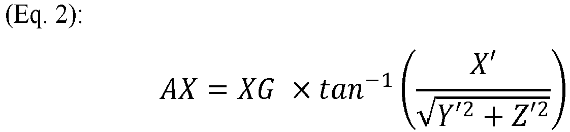
load cell assembly 14 are stored in thememory unit 32 of theload cell assembly 14. The weighing apparatus controller 60 (shown schematically inFig. 2 ) is configured to utilize these stored values to calculate actual X and Y tilt of theload cell assembly 14 very accurately, as follows. Thecontroller 60 may be connected to theconnector 38 for this purpose. In addition, thecontroller 60 is also connected to the strain gauge outputs of the load cell (e.g., via an A/D converter). - The
controller 60 is configured to retrieve the rotation matrix M from memory and to take the actual accelerometer outputs X, Y, Z and multiply them by the matrix M, to produce the alignment adjusted outputs X', Y', and Z'. Such a calculation is represented by Equation 1 below.
- Actual X tilt of the load cell assembly, designated AX, can be calculated by Equation 2 below.
- Actual Y tilt of the load cell assembly, designate AY, can be calculated by Equation 3 below.

- Thus, the
load cell assembly 14, with on-board accelerometer unit 30 and an on-board memory unit 32 storing the rotation matrix M and the gain factors XG and YG, provides an integrated package that is ready to install in any weighing apparatus that is configured to read and utilize the stored rotation matrix M and/or gain factors XG and YG to provide more accurate analysis of actual load cell tilt or offset from the horizontal. - Generally, the load cell outputs (i.e., the strain gauge outputs) are connected to an A/D circuit. Everything placed above the load cell that is not product is called dead load. This load is physically attached to the load cell is not removable. When reading the A/D counts and only dead load is present this is called scale zero, or Z. The dead load amount, or DL, may be a fixed known weight. DL is composed of the
platter 17, theweight distribution frame 16, and two bolts that secure theframe 16 into theload cell body 14. - For out of level weight compensation, the load cell must be also be calibrated after the load cell assembly is attached in the weighing apparatus (e.g., after final assembly of the complete weighing apparatus). The load cell calibration can be carried out in a manner comparable to that described in
U.S. Patent No. 9,417,116 controller 60 can also be configured to apply an electronic offset factor that is based upon the A/D converter reading at no load, and to correct for moment error. -
Fig. 7 shows an exemplary assembled food item weighing apparatus 10 including a user interface screen 80 (e.g., touch-screen interface) and alabel printer 82. In a typical item weighing operation, an item is placed on theweigh platter 17, the operator identifies the item to the weighing apparatus (e.g., by inputting an item code via the user interface 80) and the scale controller weighs the item, prices the item (e.g., applying a price per unit weight tied to the item codes) and prints and outputs a pricing label for the item (e.g., with item name, weight, price etc.). - It is to be clearly understood that the above description is intended by way of illustration and example only, is not intended to be taken by way of limitation, and that other changes and modifications are possible. For example, although the illustrated embodiment depicts both the accelerometer unit and memory unit mounted on a common PCB that is in turn mounted to the load cell body, other variations are possible. The accelerometer, or even the PCB on which the accelerometer is mounted, does not have to be mounted directly to the load cell. The accelerometer or PCB could be mounted to a plate or any other structure affixed to the load cell, as long as the result is that accelerometer position is fixed relative to the load cell body (the accelerometer does not move relative to load cell body).
Figs. 6A and 6B show other exemplary mountings of theaccelerometer unit 30 to theload cell body 18 via aPCB 31.Fig. 6C shows an exemplary mounting of theaccelerometer unit 30 to atriangular block 70 andplate structure 72 that is associated with the load cell body. In some embodiments, the accelerometer unit could be mounted in a fixed manner to the same weighing apparatus base to which the load cell body is mounted, which would also assure maintaining of a fixed position of the accelerometer unit relative to the load cell body. Regardless of the mounting, use of an appropriately determined rotation matrix can be used to rotate the coordinatesystem 74 of the accelerometer unit into alignment with the coordinatesystem 76 of the load cell body. Moreover, the position of the memory unit relative to the load cell body does not need to fixed, and thus the operative connection of the memory unit to the load cell body could be a flexible or movable connection. Still other variations are possible. - Certain implementations are described in the following numbered clauses:
- Clause 1. A weighing apparatus, comprising:
a load cell assembly comprising:- an elongated load cell body including a first three-dimensional coordinate orientation defined by a first X-axis, a first Y-axis and a first Z-axis, the elongated load cell body including a mount end for supporting the elongated load cell body and a load end for applying a load to the elongated load cell body, the elongated load cell body carrying a set of strain gauges for providing electrical outputs corresponding to load applied to the load end of the elongated load cell body;
- an accelerometer unit operatively connected to the elongated load cell body in a fixed position relative to the elongated load cell body, the accelerometer unit having a second three-dimensional coordinate orientation defined by a second X-axis, a second Y-axis and a second Z-axis, wherein the second X-axis is offset from the first X-axis, the second Y-axis is offset from the first Y-axis and the second Z-axis is offset from the first Z-axis;
- a memory unit operatively connected to the elongated load cell body, the memory unit storing a rotation matrix M that defines data for aligning the second three-dimensional coordinate orientation of the accelerometer unit with the first three-dimensional coordinate orientation of the elongated load cell body.
- Clause 2. The weighing apparatus of clause 1, wherein the memory unit further stores an accelerometer gain factor XG corresponding to a predefined change in tilt about the second X-axis and an accelerometer gain factor YG corresponding to a predefined change in tilt about the second Y-axis.
- Clause 3. The weighing apparatus of clause 2, further comprising:
- a base;
- wherein the mount end of the elongated load cell body is attached to and supported by the base, and the load end of the elongated load cell body is arranged in cantilever relative to the base;
- a controller connected to (i) read data from the memory unit, (ii) receive outputs from the accelerometer and (iii) receive outputs from the set of strain gauges.
- Clause 4. The weighing apparatus of clause 3, further comprising:
- a weight distribution frame mounted to the load end of the accelerometer; and
- a weigh platter supported on the weight distribution frame.
- Clause 5. The weighing apparatus of clause 3, wherein the controller is configured to read the rotation matrix M from the memory unit, wherein the controller is configured such that, during weighing operations of the weighing apparatus, the controller receives X, Y and Z outputs from the accelerometer and multiplies those outputs by the rotating matrix M to define alignment adjusted outputs X', Y' and Z'.
- Clause 6. The weighing apparatus of clause 5, wherein the controller is configured to calculate an X tilt and a Y tilt of the elongated load cell body based upon the gain factors XG and YG and the alignment adjusted outputs X' and Y'.
- Clause 7. The weighing apparatus of clause 6, wherein the controller is configured to calculate the X tilt and the Y tilt of the elongated load cell body as follows:


- Clause 8. The weighing apparatus of clause 1, wherein the accelerometer unit and the memory unit are both mounted on a printed circuit board, and the printed circuit board is mounted to the elongated load cell body.
- Clause 9. The weighing apparatus of clause 1, wherein memory unit comprises a flash memory unit.
- Clause 10. The weighing apparatus of clause 1, wherein the accelerometer unit is operatively connected at the mount end of the elongated load cell body.
- Clause 11. A method of producing weighing apparatus, comprising:
- utilizing load cell body including a first three-dimensional coordinate orientation defined by a first X-axis, a first Y-axis and a first Z-axis, the load cell body including:
a mount end for supporting the load cell body and a load end for applying a load to the load cell body, the load cell body carrying a set of strain gauges for providing electrical outputs corresponding to load applied to the load end of the load cell body; - providing an accelerometer unit in a fixed position relative to the load cell body and having a second three-dimensional coordinate orientation defined by a second X-axis, a second Y-axis and a second Z-axis, wherein the second X-axis is offset from the first X-axis, the second Y-axis is offset from the first Y-axis and the second Z-axis is offset from the first Z-axis;
- providing a memory unit;
- determining an offset of the second three-dimensional coordinate orientation from the first three-dimensional coordinate orientation by collecting accelerometer output values when the load cell body is in a plurality of known angular orientations; and
- storing data representing the offset in the memory unit.
- utilizing load cell body including a first three-dimensional coordinate orientation defined by a first X-axis, a first Y-axis and a first Z-axis, the load cell body including:
-
Clause 12. The method of clause 11, wherein the stored data includes a rotation matrix M that defines data for aligning the second three-dimensional coordinate orientation of the accelerometer unit with the first three-dimensional coordinate orientation of the load cell body. - Clause 13. The method of
clause 12, further comprising:- calculating an accelerometer gain factor XG corresponding to a predefined change in tilt about the second X-axis and an accelerometer gain factor YG corresponding to a predefined change in tilt about the second Y-axis; and
- storing the gain factors XG and YG in the memory unit.
-
Clause 14. The method of clause 11, wherein the accelerometer unit and the memory unit are operatively connected to the load cell body to provide a load cell assembly that is then mounted to a base of a weighing apparatus. - Clause 15. A weighing apparatus, comprising:
- a load cell body including a first three-dimensional coordinate orientation defined by a first X-axis, a first Y-axis and a first Z-axis, the load cell body including a mount end for supporting the load cell body and a load end for applying a load to the load cell body;
- an accelerometer unit connected in a fixed position relative to the load cell body and having a second three-dimensional coordinate orientation defined by a second X-axis, a second Y-axis and a second Z-axis, wherein the second X-axis is offset from the first X-axis, the second Y-axis is offset from the first Y-axis and the second Z-axis is offset from the first Z-axis;
- a memory unit associated with the weighing apparatus, the memory unit storing data for aligning the second three-dimensional coordinate orientation of the accelerometer unit with the first three-dimensional coordinate orientation of the load cell body.
-
Clause 16. The weighing apparatus of clause 15, wherein the memory unit further stores an accelerometer gain factor XG corresponding to a predefined change in tilt about the second X-axis and an accelerometer gain factor YG corresponding to a predefined change in tilt about the second Y-axis. -
Clause 17. The weighing apparatus of clause 15, wherein the data for aligning the second three-dimensional coordinate orientation of the accelerometer unit with the first three-dimensional coordinate orientation of the load cell body takes the form of a rotation matrix. -
Clause 18. The weighing apparatus of clause 15, wherein the accelerometer unit and the memory unit are both mounted on a printed circuit board, and the printed circuit board is mounted in a fixed position relative to the load cell body. - Clause 19. The weighing apparatus of
clause 16, further comprising:- a base;
- wherein the mount end of the load cell body is attached to and supported by the base, and the load end of the load cell body is arranged in cantilever relative to the base;
- a controller connected to (i) read data from the memory unit, (ii) receive outputs from the accelerometer and (iii) receive outputs from the set of strain gauges;
- wherein the controller is configured to read the data for aligning from the memory unit, wherein the controller is configured such that, during weighing operations of the weighing apparatus, the controller receives X, Y and Z outputs from the accelerometer and applies the data for aligning to the X, Y and Z outputs to define alignment adjusted outputs X', Y' and Z'.
-
Clause 20. The weighing apparatus of clause 19, wherein the controller is configured to calculate an X tilt and a Y tilt of the load cell body based upon the gain factors XG and YG and the alignment adjusted outputs X' and Y'.
Claims (15)
- A weighing apparatus, comprising:
a load cell assembly comprising:an elongated load cell body including a first three-dimensional coordinate orientation defined by a first X-axis, a first Y-axis and a first Z-axis, the elongated load cell body including a mount end for supporting the elongated load cell body and a load end for applying a load to the elongated load cell body, the elongated load cell body carrying a set of strain gauges for providing electrical outputs corresponding to load applied to the load end of the elongated load cell body;an accelerometer unit operatively connected to the elongated load cell body in a fixed position relative to the elongated load cell body, the accelerometer unit having a second three-dimensional coordinate orientation defined by a second X-axis, a second Y-axis and a second Z-axis, wherein the second X-axis is offset from the first X-axis, the second Y-axis is offset from the first Y-axis and the second Z-axis is offset from the first Z-axis;a memory unit operatively connected to the elongated load cell body, the memory unit storing a rotation matrix M that defines data for aligning the second three-dimensional coordinate orientation of the accelerometer unit with the first three-dimensional coordinate orientation of the elongated load cell body. - The weighing apparatus of claim 1, wherein the memory unit further stores an accelerometer gain factor XG corresponding to a predefined change in tilt about the second X-axis and an accelerometer gain factor YG corresponding to a predefined change in tilt about the second Y-axis.
- The weighing apparatus of claim 2, further comprising:a base;wherein the mount end of the elongated load cell body is attached to and supported by the base, and the load end of the elongated load cell body is arranged in cantilever relative to the base;a controller connected to (i) read data from the memory unit, (ii) receive outputs from the accelerometer and (iii) receive outputs from the set of strain gauges.
- The weighing apparatus of claim 3, further comprising:a weight distribution frame mounted to the load end of the accelerometer; anda weigh platter supported on the weight distribution frame.
- The weighing apparatus of claim 3, wherein the controller is configured to read the rotation matrix M from the memory unit, wherein the controller is configured such that, during weighing operations of the weighing apparatus, the controller receives X, Y and Z outputs from the accelerometer and multiplies those outputs by the rotating matrix M to define alignment adjusted outputs X', Y' and Z', and optionally wherein the controller is configured to calculate an X tilt and a Y tilt of the elongated load cell body based upon the gain factors XG and YG and the alignment adjusted outputs X' and Y', and further optionally wherein the controller is configured to calculate the X tilt and the Y tilt of the elongated load cell body as follows:


- The weighing apparatus of claim 1, wherein the accelerometer unit and the memory unit are both mounted on a printed circuit board, and the printed circuit board is mounted to the elongated load cell body, or wherein the accelerometer unit is operatively connected at the mount end of the elongated load cell body.
- The weighing apparatus of claim 1, wherein memory unit comprises a flash memory unit.
- A method of producing weighing apparatus, comprising:utilizing load cell body including a first three-dimensional coordinate orientation defined by a first X-axis, a first Y-axis and a first Z-axis, the load cell body including:
a mount end for supporting the load cell body and a load end for applying a load to the load cell body, the load cell body carrying a set of strain gauges for providing electrical outputs corresponding to load applied to the load end of the load cell body;providing an accelerometer unit in a fixed position relative to the load cell body and having a second three-dimensional coordinate orientation defined by a second X-axis, a second Y-axis and a second Z-axis, wherein the second X-axis is offset from the first X-axis, the second Y-axis is offset from the first Y-axis and the second Z-axis is offset from the first Z-axis;providing a memory unit;determining an offset of the second three-dimensional coordinate orientation from the first three-dimensional coordinate orientation by collecting accelerometer output values when the load cell body is in a plurality of known angular orientations; andstoring data representing the offset in the memory unit. - The method of claim 8, wherein the stored data includes a rotation matrix M that defines data for aligning the second three-dimensional coordinate orientation of the accelerometer unit with the first three-dimensional coordinate orientation of the load cell body, and optionally further comprising:calculating an accelerometer gain factor XG corresponding to a predefined change in tilt about the second X-axis and an accelerometer gain factor YG corresponding to a predefined change in tilt about the second Y-axis; andstoring the gain factors XG and YG in the memory unit.
- The method of claim 8, wherein the accelerometer unit and the memory unit are operatively connected to the load cell body to provide a load cell assembly that is then mounted to a base of a weighing apparatus.
- A weighing apparatus, comprising:a load cell body including a first three-dimensional coordinate orientation defined by a first X-axis, a first Y-axis and a first Z-axis, the load cell body including a mount end for supporting the load cell body and a load end for applying a load to the load cell body;an accelerometer unit connected in a fixed position relative to the load cell body and having a second three-dimensional coordinate orientation defined by a second X-axis, a second Y-axis and a second Z-axis, wherein the second X-axis is offset from the first X-axis, the second Y-axis is offset from the first Y-axis and the second Z-axis is offset from the first Z-axis;a memory unit associated with the weighing apparatus, the memory unit storing data for aligning the second three-dimensional coordinate orientation of the accelerometer unit with the first three-dimensional coordinate orientation of the load cell body.
- The weighing apparatus of claim 11, wherein the memory unit further stores an accelerometer gain factor XG corresponding to a predefined change in tilt about the second X-axis and an accelerometer gain factor YG corresponding to a predefined change in tilt about the second Y-axis.
- The weighing apparatus of claim 11, wherein the data for aligning the second three-dimensional coordinate orientation of the accelerometer unit with the first three-dimensional coordinate orientation of the load cell body takes the form of a rotation matrix.
- The weighing apparatus of claim 11, wherein the accelerometer unit and the memory unit are both mounted on a printed circuit board, and the printed circuit board is mounted in a fixed position relative to the load cell body.
- The weighing apparatus of claim 12, further comprising:a base;wherein the mount end of the load cell body is attached to and supported by the base, and the load end of the load cell body is arranged in cantilever relative to the base;a controller connected to (i) read data from the memory unit, (ii) receive outputs from the accelerometer and (iii) receive outputs from the set of strain gauges;wherein the controller is configured to read the data for aligning from the memory unit, wherein the controller is configured such that, during weighing operations of the weighing apparatus, the controller receives X, Y and Z outputs from the accelerometer and applies the data for aligning to the X, Y and Z outputs to define alignment adjusted outputs X', Y' and Z', and optionally wherein the controller is configured to calculate an X tilt and a Y tilt of the load cell body based upon the gain factors XG and YG and the alignment adjusted outputs X' and Y'.
Applications Claiming Priority (1)
| Application Number | Priority Date | Filing Date | Title |
|---|---|---|---|
| US16/784,427 US11300442B2 (en) | 2020-02-07 | 2020-02-07 | Weighing apparatus with alignment of accelerometer coordinate system and load cell coordinate system and related method |
Publications (2)
| Publication Number | Publication Date |
|---|---|
| EP3862731A1 true EP3862731A1 (en) | 2021-08-11 |
| EP3862731B1 EP3862731B1 (en) | 2025-10-22 |
Family
ID=74194656
Family Applications (1)
| Application Number | Title | Priority Date | Filing Date |
|---|---|---|---|
| EP21152687.6A Active EP3862731B1 (en) | 2020-02-07 | 2021-01-21 | Weighing apparatus and method |
Country Status (3)
| Country | Link |
|---|---|
| US (1) | US11300442B2 (en) |
| EP (1) | EP3862731B1 (en) |
| CA (1) | CA3105943C (en) |
Families Citing this family (6)
| Publication number | Priority date | Publication date | Assignee | Title |
|---|---|---|---|---|
| CN109425420B (en) * | 2017-08-29 | 2022-04-19 | 梅特勒-托利多(常州)精密仪器有限公司 | Weighing method and storage medium thereof |
| JP6771794B1 (en) * | 2020-02-25 | 2020-10-21 | 株式会社トライフォース・マネジメント | Force sensor |
| JP2023101852A (en) * | 2022-01-11 | 2023-07-24 | 大和製衡株式会社 | digital load cell |
| JP7730551B2 (en) * | 2022-02-14 | 2025-08-28 | 株式会社イシダ | Electronic scale and method for adjusting electronic scale |
| US12624982B2 (en) * | 2022-06-02 | 2026-05-12 | Electronic Theatre Controls, Inc. | Intelligent digital load cell transducer |
| CN119821699B (en) * | 2024-12-26 | 2025-11-18 | 上海航天控制技术研究所 | A high-precision and high-reliability drive shaft system device and calibration method for space applications |
Citations (4)
| Publication number | Priority date | Publication date | Assignee | Title |
|---|---|---|---|---|
| US6137065A (en) | 1993-04-23 | 2000-10-24 | Zefira; Uri | Level weighing device |
| WO2005059488A1 (en) * | 2003-12-17 | 2005-06-30 | Hottinger Baldwin Messtechnik Gmbh | Load cell |
| CN101441102A (en) * | 2007-11-21 | 2009-05-27 | 弘邦衡量控制系统股份有限公司 | Digital weighing sensor capable of returning and self-compensating deflection influence and method thereof |
| US20110119028A1 (en) * | 2009-04-28 | 2011-05-19 | Illinois Tool Works Inc. | Scale inclination calibration |
Family Cites Families (25)
| Publication number | Priority date | Publication date | Assignee | Title |
|---|---|---|---|---|
| CH445882A (en) | 1966-11-17 | 1967-10-31 | Mepag Ag | Precision balance |
| US3713333A (en) | 1971-06-24 | 1973-01-30 | Testing Technology Corp | Force measuring apparatus |
| JPS58115327A (en) | 1981-12-29 | 1983-07-09 | Teraoka Seiko Co Ltd | Electronic scale with horizontal error compensating means |
| US4438823A (en) | 1982-08-09 | 1984-03-27 | Dbi Industries, Inc. | Load cell |
| DE3234372A1 (en) | 1982-09-16 | 1984-03-22 | Sartorius GmbH, 3400 Göttingen | ELECTRIC SCALE |
| US4907179A (en) | 1987-03-09 | 1990-03-06 | Sartorius Gmbh | Electronic balance with quasi analog and digital display |
| EP0342505B1 (en) | 1988-05-17 | 1992-02-26 | Aran Engineering Development Ltd | Portable weighing scale |
| US4971177A (en) * | 1989-03-24 | 1990-11-20 | Spectra-Physics, Inc. | Data gathering system housing/mounting |
| DE3923198A1 (en) | 1989-07-13 | 1991-01-24 | Moba Electronic Mobil Automat | TRACTOR SCALE |
| US5050034A (en) | 1990-01-22 | 1991-09-17 | Endress U. Hauser Gmbh U. Co. | Pressure sensor and method of manufacturing same |
| US5623128A (en) * | 1994-03-01 | 1997-04-22 | Mettler-Toledo, Inc. | Load cell with modular calibration components |
| US5428219A (en) | 1994-04-06 | 1995-06-27 | United States Of America As Represened By The United States Department Of Energy | Fiber optic inclination detector system having a weighted sphere with reference points |
| US5646376A (en) | 1994-06-09 | 1997-07-08 | Intercomp Company | Aircraft weighing scale with improved base, platform and load cell mounting assembly |
| US5717167A (en) | 1995-01-24 | 1998-02-10 | Lts Scale Corp. | Device and method for weighing solid waste with an angle-correction scale |
| US5750937A (en) * | 1996-03-07 | 1998-05-12 | Weigh-Tronix, Inc. | Multi-load cell force sensing apparatus |
| US5992032A (en) | 1997-02-24 | 1999-11-30 | Chung-Shan Institute Of Science & Technology | Method and apparatus for inclination measurement using piezoelectric effect |
| DE19731089A1 (en) | 1997-07-19 | 1999-01-21 | Bosch Gmbh Robert | Device for determining the weight of articulated loads |
| JP4408518B2 (en) | 2000-03-10 | 2010-02-03 | 株式会社クボタ | Digital load cell unit |
| DE10152698A1 (en) | 2001-10-19 | 2003-04-30 | Hammerstein Gmbh C Rob | Detection device for the weight load of a motor vehicle seat, with a sensor and a spring body |
| US7009118B2 (en) | 2003-05-13 | 2006-03-07 | Dynamic Datum Llc | Vehicle load weighing system and load cells for such systems |
| JP4763476B2 (en) | 2006-02-22 | 2011-08-31 | 大和製衡株式会社 | Inclination error determination device, inclination error determination method, measuring instrument, and measuring method |
| GB0623802D0 (en) | 2006-11-29 | 2007-01-10 | Brown Duncan | An arrangement of interconnected devices or system to indicate loading state or overload of the axles on a vehicle |
| JP2008268147A (en) | 2007-04-25 | 2008-11-06 | Tanita Corp | Weight scale |
| WO2009077463A1 (en) | 2007-12-14 | 2009-06-25 | Siemens Aktiengesellschaft | Load cell |
| CN109425420B (en) * | 2017-08-29 | 2022-04-19 | 梅特勒-托利多(常州)精密仪器有限公司 | Weighing method and storage medium thereof |
-
2020
- 2020-02-07 US US16/784,427 patent/US11300442B2/en active Active
-
2021
- 2021-01-18 CA CA3105943A patent/CA3105943C/en active Active
- 2021-01-21 EP EP21152687.6A patent/EP3862731B1/en active Active
Patent Citations (5)
| Publication number | Priority date | Publication date | Assignee | Title |
|---|---|---|---|---|
| US6137065A (en) | 1993-04-23 | 2000-10-24 | Zefira; Uri | Level weighing device |
| WO2005059488A1 (en) * | 2003-12-17 | 2005-06-30 | Hottinger Baldwin Messtechnik Gmbh | Load cell |
| CN101441102A (en) * | 2007-11-21 | 2009-05-27 | 弘邦衡量控制系统股份有限公司 | Digital weighing sensor capable of returning and self-compensating deflection influence and method thereof |
| US20110119028A1 (en) * | 2009-04-28 | 2011-05-19 | Illinois Tool Works Inc. | Scale inclination calibration |
| US9417116B2 (en) | 2009-04-28 | 2016-08-16 | Illinois Tool Works Inc. | Weighing method and apparatus |
Also Published As
| Publication number | Publication date |
|---|---|
| US11300442B2 (en) | 2022-04-12 |
| CA3105943A1 (en) | 2021-08-07 |
| CA3105943C (en) | 2023-08-29 |
| EP3862731B1 (en) | 2025-10-22 |
| US20210247229A1 (en) | 2021-08-12 |
Similar Documents
| Publication | Publication Date | Title |
|---|---|---|
| EP3862731B1 (en) | Weighing apparatus and method | |
| CN101876565B (en) | Weighing method and apparatus | |
| US4979580A (en) | Force measuring device with sensitivity equalization | |
| EP3714240B1 (en) | Weighting method and storage medium thereof | |
| EP0403200B1 (en) | Method for scale calibration and weighing | |
| US5837946A (en) | Force sensitive scale and dual load sensor cell for use therewith | |
| US4313509A (en) | Weighing apparatus | |
| CN108801407A (en) | Weighing device, weighing method, weighing sensor and storage medium | |
| JP2008256421A (en) | Load cell and load cell unit | |
| CN216349072U (en) | Large-tonnage weight-free calibration system of discontinuous accumulation weighing apparatus | |
| EP0509735B1 (en) | Load cell balance | |
| JP4845793B2 (en) | Weighing device correction method | |
| CN118392290A (en) | Automatic calibration device for hopper scale | |
| US4757867A (en) | Single load cell weighing systems | |
| JP7685779B2 (en) | Weighing device and method using a three-axis acceleration sensor | |
| JPS58115327A (en) | Electronic scale with horizontal error compensating means | |
| KR101326280B1 (en) | Portable center of gravity measuring device | |
| CN221173574U (en) | Explosion-proof weighing device | |
| CN114858260B (en) | Bar scale combined weighing method and system | |
| KR20230156990A (en) | Apparatus and method for measuring slant usingload-cell | |
| US20070175673A1 (en) | Weight/Volume Scale | |
| KR20020082663A (en) | Apparatus and method for measuring slant using load-cell, and electrical scale and method for compensating measurement error using the same | |
| CN85108471A (en) | Electronic balance | |
| JPH05312623A (en) | Electronic balance | |
| CN121184204A (en) | A torque multiplier calibration device and method |
Legal Events
| Date | Code | Title | Description |
|---|---|---|---|
| PUAI | Public reference made under article 153(3) epc to a published international application that has entered the european phase |
Free format text: ORIGINAL CODE: 0009012 |
|
| STAA | Information on the status of an ep patent application or granted ep patent |
Free format text: STATUS: THE APPLICATION HAS BEEN PUBLISHED |
|
| AK | Designated contracting states |
Kind code of ref document: A1 Designated state(s): AL AT BE BG CH CY CZ DE DK EE ES FI FR GB GR HR HU IE IS IT LI LT LU LV MC MK MT NL NO PL PT RO RS SE SI SK SM TR |
|
| STAA | Information on the status of an ep patent application or granted ep patent |
Free format text: STATUS: REQUEST FOR EXAMINATION WAS MADE |
|
| 17P | Request for examination filed |
Effective date: 20220208 |
|
| RBV | Designated contracting states (corrected) |
Designated state(s): AL AT BE BG CH CY CZ DE DK EE ES FI FR GB GR HR HU IE IS IT LI LT LU LV MC MK MT NL NO PL PT RO RS SE SI SK SM TR |
|
| STAA | Information on the status of an ep patent application or granted ep patent |
Free format text: STATUS: EXAMINATION IS IN PROGRESS |
|
| 17Q | First examination report despatched |
Effective date: 20230912 |
|
| GRAP | Despatch of communication of intention to grant a patent |
Free format text: ORIGINAL CODE: EPIDOSNIGR1 |
|
| STAA | Information on the status of an ep patent application or granted ep patent |
Free format text: STATUS: GRANT OF PATENT IS INTENDED |
|
| INTG | Intention to grant announced |
Effective date: 20250617 |
|
| GRAS | Grant fee paid |
Free format text: ORIGINAL CODE: EPIDOSNIGR3 |
|
| GRAA | (expected) grant |
Free format text: ORIGINAL CODE: 0009210 |
|
| STAA | Information on the status of an ep patent application or granted ep patent |
Free format text: STATUS: THE PATENT HAS BEEN GRANTED |
|
| P01 | Opt-out of the competence of the unified patent court (upc) registered |
Free format text: CASE NUMBER: UPC_APP_6469_3862731/2025 Effective date: 20250909 |
|
| AK | Designated contracting states |
Kind code of ref document: B1 Designated state(s): AL AT BE BG CH CY CZ DE DK EE ES FI FR GB GR HR HU IE IS IT LI LT LU LV MC MK MT NL NO PL PT RO RS SE SI SK SM TR |
|
| REG | Reference to a national code |
Ref country code: CH Ref legal event code: F10 Free format text: ST27 STATUS EVENT CODE: U-0-0-F10-F00 (AS PROVIDED BY THE NATIONAL OFFICE) Effective date: 20251022 Ref country code: GB Ref legal event code: FG4D |
|
| REG | Reference to a national code |
Ref country code: DE Ref legal event code: R096 Ref document number: 602021040690 Country of ref document: DE |
|
| REG | Reference to a national code |
Ref country code: IE Ref legal event code: FG4D |
|
| REG | Reference to a national code |
Ref country code: NL Ref legal event code: MP Effective date: 20251022 |
|
| PG25 | Lapsed in a contracting state [announced via postgrant information from national office to epo] |
Ref country code: NL Free format text: LAPSE BECAUSE OF FAILURE TO SUBMIT A TRANSLATION OF THE DESCRIPTION OR TO PAY THE FEE WITHIN THE PRESCRIBED TIME-LIMIT Effective date: 20251022 |
|
| PGFP | Annual fee paid to national office [announced via postgrant information from national office to epo] |
Ref country code: GB Payment date: 20260127 Year of fee payment: 6 |
|
| PG25 | Lapsed in a contracting state [announced via postgrant information from national office to epo] |
Ref country code: ES Free format text: LAPSE BECAUSE OF FAILURE TO SUBMIT A TRANSLATION OF THE DESCRIPTION OR TO PAY THE FEE WITHIN THE PRESCRIBED TIME-LIMIT Effective date: 20251022 |
|
| REG | Reference to a national code |
Ref country code: LT Ref legal event code: MG9D |
|
| PG25 | Lapsed in a contracting state [announced via postgrant information from national office to epo] |
Ref country code: NO Free format text: LAPSE BECAUSE OF FAILURE TO SUBMIT A TRANSLATION OF THE DESCRIPTION OR TO PAY THE FEE WITHIN THE PRESCRIBED TIME-LIMIT Effective date: 20260122 |
|
| PGFP | Annual fee paid to national office [announced via postgrant information from national office to epo] |
Ref country code: DE Payment date: 20260128 Year of fee payment: 6 |
|
| PG25 | Lapsed in a contracting state [announced via postgrant information from national office to epo] |
Ref country code: HR Free format text: LAPSE BECAUSE OF FAILURE TO SUBMIT A TRANSLATION OF THE DESCRIPTION OR TO PAY THE FEE WITHIN THE PRESCRIBED TIME-LIMIT Effective date: 20251022 Ref country code: AT Free format text: LAPSE BECAUSE OF FAILURE TO SUBMIT A TRANSLATION OF THE DESCRIPTION OR TO PAY THE FEE WITHIN THE PRESCRIBED TIME-LIMIT Effective date: 20251022 Ref country code: FI Free format text: LAPSE BECAUSE OF FAILURE TO SUBMIT A TRANSLATION OF THE DESCRIPTION OR TO PAY THE FEE WITHIN THE PRESCRIBED TIME-LIMIT Effective date: 20251022 |
|
| REG | Reference to a national code |
Ref country code: AT Ref legal event code: MK05 Ref document number: 1849504 Country of ref document: AT Kind code of ref document: T Effective date: 20251022 |
|
| PG25 | Lapsed in a contracting state [announced via postgrant information from national office to epo] |
Ref country code: RS Free format text: LAPSE BECAUSE OF FAILURE TO SUBMIT A TRANSLATION OF THE DESCRIPTION OR TO PAY THE FEE WITHIN THE PRESCRIBED TIME-LIMIT Effective date: 20260122 |
|
| PG25 | Lapsed in a contracting state [announced via postgrant information from national office to epo] |
Ref country code: IS Free format text: LAPSE BECAUSE OF FAILURE TO SUBMIT A TRANSLATION OF THE DESCRIPTION OR TO PAY THE FEE WITHIN THE PRESCRIBED TIME-LIMIT Effective date: 20260222 |
|
| PGFP | Annual fee paid to national office [announced via postgrant information from national office to epo] |
Ref country code: FR Payment date: 20260126 Year of fee payment: 6 |
|
| PG25 | Lapsed in a contracting state [announced via postgrant information from national office to epo] |
Ref country code: PT Free format text: LAPSE BECAUSE OF FAILURE TO SUBMIT A TRANSLATION OF THE DESCRIPTION OR TO PAY THE FEE WITHIN THE PRESCRIBED TIME-LIMIT Effective date: 20260223 |
|
| PG25 | Lapsed in a contracting state [announced via postgrant information from national office to epo] |
Ref country code: PL Free format text: LAPSE BECAUSE OF FAILURE TO SUBMIT A TRANSLATION OF THE DESCRIPTION OR TO PAY THE FEE WITHIN THE PRESCRIBED TIME-LIMIT Effective date: 20251022 |
|
| PG25 | Lapsed in a contracting state [announced via postgrant information from national office to epo] |
Ref country code: LV Free format text: LAPSE BECAUSE OF FAILURE TO SUBMIT A TRANSLATION OF THE DESCRIPTION OR TO PAY THE FEE WITHIN THE PRESCRIBED TIME-LIMIT Effective date: 20251022 |
|
| PG25 | Lapsed in a contracting state [announced via postgrant information from national office to epo] |
Ref country code: BG Free format text: LAPSE BECAUSE OF FAILURE TO SUBMIT A TRANSLATION OF THE DESCRIPTION OR TO PAY THE FEE WITHIN THE PRESCRIBED TIME-LIMIT Effective date: 20251022 |