EP3862638A1 - Outdoor unit and refrigeration cycle device - Google Patents
Outdoor unit and refrigeration cycle device Download PDFInfo
- Publication number
- EP3862638A1 EP3862638A1 EP18936127.2A EP18936127A EP3862638A1 EP 3862638 A1 EP3862638 A1 EP 3862638A1 EP 18936127 A EP18936127 A EP 18936127A EP 3862638 A1 EP3862638 A1 EP 3862638A1
- Authority
- EP
- European Patent Office
- Prior art keywords
- cross
- section
- side wall
- distance
- sectional area
- Prior art date
- Legal status (The legal status is an assumption and is not a legal conclusion. Google has not performed a legal analysis and makes no representation as to the accuracy of the status listed.)
- Granted
Links
Images




Classifications
-
- F—MECHANICAL ENGINEERING; LIGHTING; HEATING; WEAPONS; BLASTING
- F24—HEATING; RANGES; VENTILATING
- F24F—AIR-CONDITIONING; AIR-HUMIDIFICATION; VENTILATION; USE OF AIR CURRENTS FOR SCREENING
- F24F1/00—Room units for air-conditioning, e.g. separate or self-contained units or units receiving primary air from a central station
- F24F1/06—Separate outdoor units, e.g. outdoor unit to be linked to a separate room comprising a compressor and a heat exchanger
- F24F1/40—Vibration or noise prevention at outdoor units
-
- F—MECHANICAL ENGINEERING; LIGHTING; HEATING; WEAPONS; BLASTING
- F24—HEATING; RANGES; VENTILATING
- F24F—AIR-CONDITIONING; AIR-HUMIDIFICATION; VENTILATION; USE OF AIR CURRENTS FOR SCREENING
- F24F1/00—Room units for air-conditioning, e.g. separate or self-contained units or units receiving primary air from a central station
- F24F1/06—Separate outdoor units, e.g. outdoor unit to be linked to a separate room comprising a compressor and a heat exchanger
- F24F1/46—Component arrangements in separate outdoor units
- F24F1/48—Component arrangements in separate outdoor units characterised by air airflow, e.g. inlet or outlet airflow
-
- F—MECHANICAL ENGINEERING; LIGHTING; HEATING; WEAPONS; BLASTING
- F24—HEATING; RANGES; VENTILATING
- F24F—AIR-CONDITIONING; AIR-HUMIDIFICATION; VENTILATION; USE OF AIR CURRENTS FOR SCREENING
- F24F1/00—Room units for air-conditioning, e.g. separate or self-contained units or units receiving primary air from a central station
- F24F1/06—Separate outdoor units, e.g. outdoor unit to be linked to a separate room comprising a compressor and a heat exchanger
- F24F1/46—Component arrangements in separate outdoor units
- F24F1/48—Component arrangements in separate outdoor units characterised by air airflow, e.g. inlet or outlet airflow
- F24F1/54—Inlet and outlet arranged on opposite sides
-
- F—MECHANICAL ENGINEERING; LIGHTING; HEATING; WEAPONS; BLASTING
- F24—HEATING; RANGES; VENTILATING
- F24F—AIR-CONDITIONING; AIR-HUMIDIFICATION; VENTILATION; USE OF AIR CURRENTS FOR SCREENING
- F24F1/00—Room units for air-conditioning, e.g. separate or self-contained units or units receiving primary air from a central station
- F24F1/06—Separate outdoor units, e.g. outdoor unit to be linked to a separate room comprising a compressor and a heat exchanger
- F24F1/56—Casing or covers of separate outdoor units, e.g. fan guards
-
- F—MECHANICAL ENGINEERING; LIGHTING; HEATING; WEAPONS; BLASTING
- F24—HEATING; RANGES; VENTILATING
- F24F—AIR-CONDITIONING; AIR-HUMIDIFICATION; VENTILATION; USE OF AIR CURRENTS FOR SCREENING
- F24F1/00—Room units for air-conditioning, e.g. separate or self-contained units or units receiving primary air from a central station
- F24F1/06—Separate outdoor units, e.g. outdoor unit to be linked to a separate room comprising a compressor and a heat exchanger
- F24F1/38—Fan details of outdoor units, e.g. bell-mouth shaped inlets or fan mountings
-
- F—MECHANICAL ENGINEERING; LIGHTING; HEATING; WEAPONS; BLASTING
- F24—HEATING; RANGES; VENTILATING
- F24F—AIR-CONDITIONING; AIR-HUMIDIFICATION; VENTILATION; USE OF AIR CURRENTS FOR SCREENING
- F24F13/00—Details common to, or for air-conditioning, air-humidification, ventilation or use of air currents for screening
- F24F13/24—Means for preventing or suppressing noise
Definitions
- the present disclosure relates to an outdoor unit and a refrigeration cycle apparatus, and more particularly to a configuration of an air flow passage in the outdoor unit in which a heat exchanger and a fan are provided.
- An outdoor unit of an existing refrigeration cycle apparatus includes a partition plate that serves as a partition between an air flow passage in which a heat exchanger and a fan are provided and a machine chamber in which a compressor and other components are provided.
- the air flow passage is defined by the partition plate, a top plate, and a bottom plate, and the fan is driven to cause outside air to flow into the air flow passage through an inlet port, to send the outside air to the heat exchanger, and to blow the outside air through an outlet port.
- the partition plate is shaped in such a manner as to protrude toward a machine chamber side, and the air flow passage is partially widened.
- Patent Literature 1 Japanese Unexamined Patent Application Publication No. 2010-127590
- Patent Literature 1 In an outdoor unit of a refrigeration cycle apparatus disclosed in Patent Literature 1, only one fan is provided in an air flow passage, and if two fans are arranged side by side, and then even if a partition plate provided close to the fans is formed to have a recessed portion, the velocity of wind is non-uniform, and noise cannot be reduced.
- the present disclosure is applied to solve the above problem, and relates to reduction of noise caused by suction air at an outdoor unit provided with two fans and at a refrigeration cycle apparatus.
- An outdoor unit includes: a housing in which an inlet port and an outlet port are formed; a bottom plate that forms a lower surface of the housing, a top plate that forms an upper surface of the housing, and a side wall that is provided between the bottom plate and the top plate to partition an internal space of the housing; a heat exchanger provided in a region in the housing that adjoins the inlet port; and fans provided in a region in the housing that adjoins the outlet port.
- the fans are a first fan and a second fan that are respectively provided in an upper side and a lower side of the region in the housing that adjoins the outlet port.
- An air flow passage is provided to extend from the heat exchanger to the fans, and is defined by the bottom plate, the top plate, and the side wall, the side wall being located beside the fans.
- Cross sections of regions of the air flow passage that are located between central axes of the fans and the side wall have respective cross-sectional areas A, B, and C such that the cross-sectional area B ⁇ the cross-sectional area A ⁇ the cross-sectional area C is satisfied, where the cross-sectional area A is a cross-sectional area of a first cross section that is located between the central axis of the first fan and the top plate and is parallel to the bottom plate, the cross-sectional area B is a cross-sectional area of a second cross section that is located between the central axis of the second fan and the bottom plate and is parallel to the bottom plate, and the cross-sectional area C is a cross-sectional area of a third cross section that is located between the first cross section and the second cross section and is parallel to the bottom plate.
- the cross sectional area of a region of the air flow passage that extends from the side wall toward center lines of the fans varies in a direction along the height of the outdoor unit, that is, cross sections of regions of the above region of the air flow passage that are located at different locations in the above height direction of the outdoor unit have different areas, whereby it is possible to eliminate non-uniformity of a wind velocity distribution in a region of the air flow passage that is close to the side wall and to thus reduce noise.
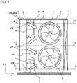
- Fig. 1 is a schematic view illustrating an internal configuration of an outdoor unit 100 according to Embodiment 1 as viewed from a back side of the outdoor unit 100.
- Fig. 1 illustrates the outdoor unit 100 as viewed from the back side, and a section taken in a direction perpendicular to rotational axes of fans 4 and 5 at a location between a heat exchanger 3 provided on the back side and the fans 4 and 5.
- Fig. 1 is a schematic view illustrating an internal configuration of an outdoor unit 100 according to Embodiment 1 as viewed from a back side of the outdoor unit 100.
- Fig. 1 illustrates the outdoor unit 100 as viewed from the back side, and a section taken in a direction perpendicular to rotational axes of fans 4 and 5 at a location between a heat exchanger 3 provided on the back side and the fans 4 and 5.
- Fig. 1 is a schematic view illustrating an internal configuration of an outdoor unit 100 according to Embodiment 1 as viewed from a back side of the outdoor unit
- an x direction is a width direction of the outdoor unit 100 that is a direction parallel to the width of the outdoor unit 100; a y direction is a height direction of the outdoor unit 100 that is a direction parallel to the height of the outdoor unit 100; and a z direction perpendicular to x-axis and y-axis is parallel to the rotational axes of the fans 4 and 5.
- the outdoor unit 100 as illustrated in Fig. 1 is included in an air-conditioning apparatus or a refrigeration cycle apparatus such as a refrigerator.
- a compressor, a four-way valve, an outdoor heat exchanger, an expansion device, and an indoor heat exchanger are connected by refrigerant pipes to form a refrigerant circuit.
- the outdoor unit 100 includes a housing 2 having a top plate 8 that forms an upper surface of the housing 2 and a bottom plate 9 that forms a lower surface of the housing 2.
- the inside of the housing 2 is partitioned into an air-sending chamber 6 and a machine chamber 7 by a side wall 10.
- the heat exchanger 3 is provided on an inlet-port side
- the fan 4 is provided on an outlet-port side.
- a compressor, electric components, and other components are provided in the machine chamber 7, a compressor, electric components, and other components are provided.
- the fans 4 and 5 send outside air to the heat exchanger 3, and heat exchange is performed between the outside air and refrigerant.
- the outdoor unit 100 includes the air-sending chamber 6 in which the fans 4 and 5, that is, a first fan 4 and a second fan 5, are arranged side by side in the y direction.
- the fan located closer to the top plate 8 is sometimes referred to as the first fan 4
- the fan located closer to the bottom plate 9 is sometimes referred to as the second fan 5.
- the fans 4 and 5 are provided such that the rotational axes of these fans coincide with each other in the x direction.
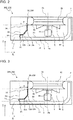
- Fig. 2 is a schematic view illustrating an internal configuration of the outdoor unit 100 according to Embodiment 1 as viewed from an upper side of the outdoor unit 100.
- Fig. 2 illustrates the internal configuration of a cross section of part a-a of the outdoor unit 100 that is taken along line a-a in Fig. 1 ; however, in order to describe a positional relationship between the side wall 10 and the fans 4 and 5, Fig. 2 does not illustrate a sectional configuration of each of the fans 4 and 5, and simply illustrates an external appearance of each fan as viewed from above.
- the section of the part a-a indicated in Fig. 1 is a first section that is located closer to the top plate 8 than to at least the central axis of the fan 4 and that is located parallel to the bottom plate 9.
- the heat exchanger 3 is located to adjoin an inlet port 20, and the fans 4 and 5 are located to adjoin an outlet port 21.
- the heat exchanger 3 is L-shaped as viewed from the upper side of the housing 2, and outside air that flows into the outdoor unit 100 from a back surface and a side of the outdoor unit 100 passes through the heat exchanger 3.
- Each of the fans 4 and 5 includes blades 40 arranged around the rotational axis.
- Each of the fans 4 and 5 further has a bell mouth 41 located outward of outer circumferential portions of the blades 40. Air in the air-sending chamber 6 is made to flow into the bell mouth 41 and then flow out through the outlet port 21 by the rotation of the blades 40 located inward of the bell mouth 41.
- the side wall 10 is located close to the machine chamber 7.
- the side wall 10 is provided between the top plate 8 and the bottom plate 9 and serves as, in Embodiment 1, a partition plate between the air-sending chamber 6 and the machine chamber 7.
- a side-wall upper portion 10a in the section as illustrated in Fig. 2 is formed in such a manner as to narrow an air flow passage in a direction from the heat exchanger 3 toward the fans 4 and 5.
- a surface of the side-wall upper portion 10a is formed to narrow the air-sending chamber 6 in the x direction such that the distance by which the air-sending chamber 6 is narrowed increases in the z direction.
- the air flow passage is a passage in which air that has passed through the heat exchanger 3 passes through the air-sending chamber 6.
- the side-wall upper portion 10a has a guide surface 11a that is inclined toward the rotational axis of the fan 4 in a direction from the heat exchanger 3 toward the fan 4. That is, an upstream end portion 12a of the guide surface 11a is closer to the machine chamber 7 than a downstream end portion 13a of the guide surface 11a.
- the cross-sectional shape of the guide surface 11a is not limited to a linear shape, and may be, for example, a curved shape such that the guide surface 11a protrudes toward the air flow passage or protrudes in a direction away from the air flow passage.
- guide surfaces 11b and 11c which will be described below.
- a region Ha as illustrated in Fig. 2 is defined by a line parallel to a rotational axis 44 of each of the fans 4 and 5, a line parallel to an end face 42 of the bell mouth 41, a line that extends from the end face 42 of the bell mouth 41 and along the surface on the upstream side of the side-wall upper portion 10a, and a line parallel to a surface of the heat exchanger 3 that faces the fans 4 and 5.
- the region defined by a dotted line in Fig. 2 is a cross section of a region of the air flow passage that is located from the central axes of the fans 4 and 5 to the side-wall upper portion 10a.
- the area of the region Ha corresponds to a cross-sectional area A of the air flow passage between the central axis of each of the fans 4 and 5 and the side wall 10 in the first cross section as illustrated in Fig. 2 .
- the side-wall upper portion 10a in the first cross section protrudes by a protrusion amount P in the x direction.
- the protrusion amount P is the distance between an imaginary line that extends, in the y direction, from an end portion 14 of the inlet port 20 that adjoins the machine chamber 7 and part of the side wall 10 that most greatly protrudes in the x direction.
- the protrusion amount P is the distance between the end portion 14 of the inlet port 20 that adjoins the machine chamber 7 and the part of the side wall 10 that most greatly protrudes toward the air flow passage side.
- a protrusion distance Q and a protrusion distance R which will be described below.
- the part of the side-wall upper portion 10a that protrudes toward the air flow passage side is located, in the z direction, between the heat exchanger 3 and the end face 42 of the bell mouth 41.
- Figs. 3 and 4 are schematic views each illustrating an internal configuration of the outdoor unit 100 according to Embodiment 1 as viewed from the upper side of the outdoor unit 100.
- Fig. 3 illustrates a cross section of part b-b of the outdoor unit 100 that is taken along line b-b in Fig. 1
- Fig. 4 illustrates a cross section of part c-c of the outdoor unit 100 that is taken along line c-c in Fig. 1 .
- the protrusion amount of the side wall 10 toward the air flow passage side in the outdoor unit 100 varies between the cross section of the part a-a, the cross section of the part b-b, and the cross section of the part c-c.
- all the above cross sections of the side wall 10 are shaped such that the distance by which the air flow passage is narrowed increases from the heat exchanger 3 toward the fans 4 and 5.
- the cross section of the part b-b is a second cross section that is located closer to the bottom plate 9 than at least the central axis of the second fan 5, and that is parallel to the bottom plate 9.
- a side-wall lower portion 10b as illustrated in Fig. 3 has a guide surface 11b that is inclined toward the rotational axis of the fan 4 in a direction from the heat exchanger 3 toward the fan 4, and an upstream end portion 12b of the guide surface 11b is closer to the machine chamber 7 than a downstream end portion 13b of the guide surface 11b.
- the area of a region Hb corresponds to a cross-sectional area B of the air flow passage between the central axis of the each of the fans 4 and 5 and the side wall 10.
- the side-wall lower portion 10b protrudes by a protrusion amount Q.
- the protrusion amount Q is larger than the protrusion amount P in the first cross section as illustrated in Fig. 2
- the cross-sectional area B of the air flow passage in the second cross section as illustrated in Fig. 3 is smaller than the cross-sectional area A of the air flow passage in the first cross section as illustrated in Fig. 2 .
- the downstream end portion 13b of the guide surface 11b is closer to the heat exchanger 3 than the downstream end portion 13a of the guide surface 11a of the first cross section.
- the cross section of the part c-c is a third cross section that is located in a middle region between the first fan 4 and the second fan 5. More specifically, the third cross section is located between the central axis of the first fan 4 and the central axis of the second fan 5.
- a side-wall middle portion 10c as illustrated in Fig. 4 is formed in such a manner as to narrow the air flow passage in the direction from the heat exchanger 3 toward the fans 4 and 5.
- the side-wall middle portion 10c has the guide surface 11c that is inclined toward the rotational axis of the fan 4 in the direction from the heat exchanger 3 toward the fan 4, and an upstream end portion 12c of the guide surface 11c is closer to the machine chamber 7 than a downstream end portion 13c.
- the area of a region Hc corresponds to a cross-sectional area C of a region of the air flow passage that is located between the central axis of each of the fans 4 and 5 and the side wall 10.
- the side-wall middle portion 10c protrudes by a protrusion amount R.
- the protrusion amount R in the third cross section is smaller than the protrusion amount P in the first cross section as illustrated in Fig. 2 .
- a cross-sectional area C of the air flow passage of the third cross section as illustrated in Fig. 4 is greater than a cross-sectional area A of the air flow passage in the first cross section as illustrated in Fig. 2 . That is, a region Hc as indicated in Fig. 4 is larger than the region Ha as indicated in Fig. 2 .
- a downstream end portion 13c of a guide surface 11c is closer to the fans 4 and 5 than the downstream end portion 13c of the guide surface 11a of the first cross section.
- the side wall 10 of the outdoor unit 100 has the side-wall upper portion 10a that is closer to the top plate side than the central axis of the first fan 4, the side-wall lower portion 10b that is closer to the bottom plate side than the central axis of the second fan 5, and the side-wall middle portion 10c that is located between the central axis of the first fan 4 and the central axis of the second fan 5.
- the cross-sectional area A that is the area of the region Ha of the air flow passage in the first cross section in which the side-wall upper portion 10a is located
- the cross-sectional area B that is the area of the region Hb in the air flow passage in the second cross section in which the side-wall lower portion 10b is located
- the cross-sectional area C that is the area of the region Hc of the air flow passage in the third cross section in which the side-wall middle portion 10c is located satisfy the relationship "B ⁇ A ⁇ C".
- the side-wall upper portion 10a, the side-wall lower portion 10b, and the side-wall middle portion 10c protrudes toward the air flow passage side by different protrusion amounts, and the protrusion amount P of the side-wall upper portion 10a, the protrusion amount Q of the side-wall lower portion 10b, and the protrusion amount R of the side-wall middle portion 10c satisfies the relationship "R ⁇ P ⁇ Q".
- Embodiment 1 in the side wall 10 having portions that have the first cross section, the second cross section, and the third cross section, regarding the length (creepage distance) of a line that extends, along the surface of the side wall 10, from a surface of the heat exchanger 3 that is closer to the fans 4 and 5 toward the end face 42 of the bell mouth 41 of each of the fans 4 and 5, the length of the above line in the second cross section is the greatest, and the length of the above line in the third cross section is the smallest. That is, a creepage distance La in the first cross section, a creepage distance Lb in the second cross section, and a creepage distance Lc in the third cross section satisfy the relationship "Lc ⁇ La ⁇ Lb".
- the first cross section is a cross section that is located between at least the central axis of the first fan 4 and the top plate 8, and that is parallel to the bottom plate 9.
- the second cross section is a cross section that is located between at least the second fan 5 and the bottom plate 9, and that is parallel to the bottom plate 9.
- the third cross section is a cross section that is located between the first cross section and the second cross section, and that is parallel to the bottom plate 9.
- Fig. 5 is a schematic view illustrating an internal configuration of an outdoor unit 100a that is a modification of the outdoor unit 100 according to Embodiment 1 as viewed from an upper side of the outdoor unit 100a.
- Fig. 5 illustrates a cross section of part c-c that is taken along line c-c in Fig. 1 as a representative, and side walls 110 that are taken line a-a and line b-b in Fig. 1 are indicated by dashed-dotted lines.
- part of the side wall 110 that is located between points 15 and 16 is shaped to be recessed in a direction away from the air flow passage.
- each of guide surfaces 111a, 111 b, and 111c of the side wall 110 forms a curved surface that is located between the points 15 and 16 and that protrudes toward the machine chamber 7.
- the creepage distance Lc in the third cross section is the greatest and the creepage distance Lb in the second cross section is the smallest.
- the creepage distance La in the first cross section, the creepage distance Lb in the second cross section, and the creepage distance Lc in the third cross section satisfy the relationship "Lb ⁇ La ⁇ Lc".
- the cross-sectional area A of the air flow passage in the first cross section, the cross-sectional area B of the air flow passage in the second cross section, and the cross-sectional area C of the air flow passage in the third cross section satisfy the relationship "B ⁇ A ⁇ C".
- Fig. 6 is a schematic view illustrating an internal configuration of an outdoor unit 1000 as a comparative example that is to be compared with the outdoor unit 100 according to Embodiment 1, as viewed from a back side of the outdoor unit 1000.
- the outdoor unit 1000 of the comparative example has the same configuration as the outdoor unit 100 according to Embodiment 1, except for only the side wall; that is, the side wall of the outdoor unit 1000 of the comparative example is different from the side wall 10 of the outdoor unit 100.
- a side wall 1010 of the outdoor unit 1000 of the comparative example has a uniform cross-sectional shape between the top plate 8 and the bottom plate 9.
- the cross-sectional area of the air flow passage does not vary in the height direction throughout the entire region of the outdoor unit 1000.
- the outdoor unit 100 of Embodiment 1 and the outdoor unit 1000 of the comparative example in a region between the side wall 1010 and the fans 4 and 5 that are propeller fans, the velocity of suction air in a region corresponding to a region between the first fan 4 and the second fan 5 is high.
- a tip flow having a strength depending on the difference in pressure between a pressure surface and the suction surface is generated.
- two propeller fans are provided side by side as in the outdoor units 100 and 1000, as illustrated in Fig.
- the velocity of suction air v2 in a region that is located close to the side wall 1010 and corresponds to the region between the first fan 4 and the second fan 5 is the highest.
- suction air v1 is suction air in a region close to the side wall 1010 and the top plate 8
- suction air v3 is suction air in a region close to the side wall 1010 and the bottom plate 9
- the velocity of the suction air v1 is higher than the velocity of the suction air v3.
- air that has flowed into the air flow passage flows at a high velocity in a region in which the width of air flow passage is small and flows at a low velocity in a region in which the width of the air flow passage is great.
- the cross-sectional shape of the side wall 1010 is uniform between the top plate 8 and the bottom plate 9.
- the cross-sectional area of the air-sending chamber 6 is uniform in the y direction of the outdoor unit 1000, the width of the air flow passage is thus also uniform, and the velocities of suction air v1, v2, and v3 are non-uniform.
- the side-wall upper portion 10a, the side-wall lower portion 10b, and the side-wall middle portion 10c have different shapes, and respective regions of the air flow passage that are associated with the side-wall upper portion 10a, the side-wall lower portion 10b, and the side-wall middle portion 10c have different widths. That is, in the outdoor unit 100, the cross-sectional area A in the air flow passage in the first cross section, the cross-sectional area B in the air flow passage in the second cross section, and the cross-sectional area C in the air flow passage in the third cross section satisfy the relationship "B ⁇ A ⁇ C".
- the third cross section in which the air velocity is the highest in the outdoor unit 1000 of the comparative example, has the greatest cross-sectional area in the air flow passage
- the second cross section in which the air velocity is the lowest in the outdoor unit 1000, has the smallest cross-sectional area in the air flow passage.
- An outdoor unit 200 according to Embodiment 2 has the same configuration of the outdoor unit 100 according to Embodiment 1, except for the shape of the side wall 10.
- the outdoor unit 200 according to Embodiment 2 will be described by referring mainly to the difference between Embodiments 1 and 2.
- components as illustrated in figures that have the same functions as those in Embodiment 1 will be denoted by the same reference signs.
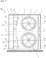
- Fig. 7 is a schematic view illustrating an internal configuration of the outdoor unit 200 according to Embodiment 2 as viewed from a back side of the outdoor unit 200.
- a side wall 210 of the outdoor unit 200 has a side-wall middle-upper portion 10d between the side-wall upper portion 10a and the side-wall middle portion 10c, and has a side-wall middle-lower portion 10e between the side-wall middle portion 10c and the side-wall lower portion 10b.
- Part d-d as indicated in Fig. 7 corresponds to a fourth cross section that is located between the first cross section that corresponds to part a-a as indicated in Fig. 7 and the second cross section that corresponds to part c-c as indicated in Fig. 7 , and that is parallel to the bottom plate 9.
- the fourth cross section is a cross section that passes through the side-wall middle-upper portion 10d.
- Part e-e as indicated in Fig. 7 is a fifth cross section that is located between the third cross section that corresponds to part c-c as indicated in Fig. 7 and the second cross section that corresponds to part b-b as indicated in Fig. 7 , and the fifth cross section is parallel to the bottom plate 9.
- the fifth cross section is a cross section including the side-wall middle-lower portion 10e.
- Fig. 8 is a schematic view illustrating an internal configuration of the outdoor unit 200 according to Embodiment 2 as viewed from an upper side of the outdoor unit 200.
- Fig. 8 illustrates the internal configuration of part d-d and part e-e as indicated in Fig. 7 in the outdoor unit 100.
- a dashed-dotted line in Fig. 8 indicates the shape of the part e-e of the side wall 210 as indicated in Fig. 7 .
- the side-wall middle-upper portion 10d has the same shape as the side-wall upper portion 10a in the first cross section, and also has a guide surface 11d having an upstream end portion 12d that is closer to the machine chamber 7 than a downstream end portion 13d.
- the side-wall middle-lower portion 10e also has the same shape as the side-wall upper portion 10a, and has a guide surface 11e having an upstream end portion 12e that is closer to the machine chamber 7 than a downstream end portion 13e.
- the cross-sectional area D that is the area of the region Hd of the air flow passage in the fourth cross section in which the side-wall middle-upper portion 10d is located
- the cross-sectional area E that is the area of the region He in the air flow passage in the fifth cross section in which the side-wall middle-lower portion 10e is located
- the cross-sectional area A in the air flow passage in the first cross section
- the cross-sectional area Bin the air flow passage in the second cross section
- the cross-sectional area C in the air flow passage in the third cross section satisfy "B ⁇ A ⁇ E ⁇ D ⁇ C".
- the side-wall upper portion 10a, the side-wall lower portion 10b, the side-wall middle portion 10c, the side-wall middle-upper portion 10d, and the side-wall middle-lower portion 10e protrude toward the air flow passage side by different protrusion amounts, and the protrusion amount S of the side-wall middle-upper portion 10d, the protrusion amount T of the side-wall middle-lower portion 10e, the protrusion amount P, the protrusion amount Q, and the protrusion amount R satisfy "R ⁇ T ⁇ S ⁇ P ⁇ Q".
- Embodiment 2 in part of the side wall 10 that is located from the first cross section to the fifth cross section, regarding the length (creepage distance) of a line along a surface of part of the side wall 10 that extends from the surface of the heat exchanger 3 that is closer to the fans 4 and 5 to the end face 42 of the bell mouth 41 of each of the fans 4 and 5, the length of the line in the second cross section is the greatest, and the length of the line in the third cross section is the smallest.
- the creepage distance Ld in the fourth cross section corresponding to the part d-d indicated in Fig. 7 the creepage distance Le in the fifth cross section corresponding to the part e-e indicated in Fig.
- the creepage distance La in the first cross section, the creepage distance Lb in the second cross section, and the creepage distance Lc in the third cross section satisfy the relationship "Lc ⁇ Le ⁇ Ld ⁇ La ⁇ Lb".
- the above relationship is established in the case where the side wall 210 in each of the first cross section, the second cross section, the third cross section, the fourth cross section, and the fifth cross section is formed in such a manner as to protrude toward the air flow passage side. That is, the relationship "Lc ⁇ Le ⁇ Ld ⁇ La ⁇ Lb" is established in the case where part of the side wall 10 that is located between points 15 and 16 as illustrated in Figs. 2 to 4 and 7 is formed to protrude toward the air-sending chamber 6.
- the creepage distances of the first cross section to the fifth cross section satisfy "Lb ⁇ La ⁇ Ld ⁇ Le ⁇ Lc".
- the outdoor unit 200 according to Embodiment 2 it is possible to reduce the velocity of suction air even in regions adjacent to the side-wall middle-upper portion 10d and the side-wall middle-lower portion 10e that are regions close to the fans 4 and 5 and in which the suction air tends to flow at a higher velocity, and also to further reduce non-uniformity of the velocities of suction air v1, v2, and v3 than in the outdoor units 100 and 100a according to Embodiment 1.
- the air flow in the vicinity of the side wall 210 is averaged, whereby the fluctuation of the flow field of air around the blades of the fans 4 and 5 is reduced, and the pressure fluctuation at surfaces of the blades 40 of the fans 4 and 5 is also reduced.
- the magnitude of the sound caused by rotation of the fans 4 and 5 is reduced, and the noise can be reduced.
- Fig. 9 is a schematic view illustrating an internal configuration of the outdoor unit 200 according to Embodiment 2 as viewed from the upper side of the outdoor unit 200.
- the side wall 210 of the outdoor unit 200 is formed to partially protrude toward the air flow passage side.
- a plate can be attached to part of a partition plate 90, which adjoins the inlet port 20, the partition plate 90 serving as a partition between the air-sending chamber 6 and the machine chamber 7.
- each of the regions Ha to He in the air flow passage is determined by extending an imaginary line from a most protruding point of the side wall 210a, which most greatly protrudes in the x direction, in the y direction until the imaginary line intersects the end face 42 of the bell mouth 41. That is, in the case illustrated in Fig. 9 , a region that is covered by the side wall 210a as viewed from an upstream side of the air flow passage is not included in the air flow passage.
- An outdoor unit 300 according to Embodiment 3 has the same configuration as the outdoor unit 100 according to Embodiment 1 except for the setting of cross-sectional areas A, B, and C of the regions Ha, Hb, and Hc.
- the outdoor unit 300 according to Embodiment 3 will be described by referring mainly to the differences between Embodiments 1 and 3.
- components as illustrated in figures that have the same functions as those in Embodiment 1 will be denoted by the same reference signs.
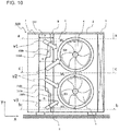
- Fig. 10 is a schematic view illustrating an internal configuration of the outdoor unit 300 according to Embodiment 3 as viewed from a back side of the outdoor unit 300.
- Fig. 11 is a schematic view illustrating an internal configuration of the outdoor unit 300 according to Embodiment 3 as viewed from an upper side of the outdoor unit 300.
- Fig. 11 illustrates the internal configuration of each of part a-a, part b-b, and part c-c as illustrated in Fig. 10 in the outdoor unit 300.
- a dashed-dotted line in Fig. 11 indicates the shape of a side-wall upper portion 310a in the part a-a as illustrated in Fig. 10 .
- FIG. 11 indicates the shape of a side-wall lower portion 310b in the part b-b as illustrated in Fig. 10 .
- a solid line in Fig. 11 illustrates the shape of a side-wall middle portion 310c in the part c-c as illustrated in Fig. 10 .
- the protrusion amount P of the side-wall upper portion 310a, the protrusion amount Q of the side-wall lower portion 310b, and the protrusion amount R of the side-wall middle portion 310c are set equal to each other, and cross-sectional areas A, B, and C in the air flow passage are different from each other since the upstream end portions 12a, 12b, and 12c of the guide surfaces 11a, 11b, and 11c are located at different positions.
- the cross-sectional area A that is the area of the region Ha of the air flow passage in the first cross section in which the side-wall upper portion 310a is provided
- the cross-sectional area B that is the area of the region Hb of the air flow passage in the second cross section in which the side-wall lower portion 310b is provided
- the cross-sectional area C that is the area of the region Hc of the flow passage in the third cross section in which the side-wall middle portion 310c is provided satisfy "B ⁇ A ⁇ C" as in Embodiment 1.
- the upstream end portion 12b of the side-wall lower portion 310b is the closest to the fans 4 and 5
- the upstream end portion 12a of the side-wall upper portion 310a is second closest to the fans 4 and 5
- the upstream end portion 12c of the side-wall middle portion 310c is the furthest from the fans 4 and 5. That is, where Wa, Wb, and Wc are the distances between the upstream end portions 12a, 12b, and 12c and the center line of each of the fans, respectively, the relationship "Wb ⁇ Wa ⁇ Wc" is satisfied.
- the non-uniformity of the velocities v1, v2, and v3 of suction air can be reduced as in Embodiment 1. Also, in the outdoor unit 300 according to Embodiment 3, the amplitude of sound caused by rotation of the fans 4 and 5 is reduced, and noise can also be reduced.
- the outdoor unit 300 in the outdoor unit 300 according to Embodiment 3, in the case where a side-wall middle-upper portion 310d is provided between the side-wall upper portion 310a and the side-wall middle portion 310c, and a side-wall middle-lower portion e is provided between the side-wall middle portion 310c and the side-wall lower portion 310b, where Wd and We are the distance between the center line of each of the fans and the upstream end portion 12d of the guide surface 11d in the side-wall middle-upper portion 310d and the distance between the center line of each fans and the upstream end portion 12e of the guide surface 11e in the side-wall middle-lower portion 310e, respectively, the relationship "Wb ⁇ Wa ⁇ We ⁇ Wd ⁇ Wc" is satisfied.
- the outdoor unit 300 can obtain similar advantages to those of Embodiment 2.
Landscapes
- Engineering & Computer Science (AREA)
- Chemical & Material Sciences (AREA)
- Combustion & Propulsion (AREA)
- Mechanical Engineering (AREA)
- General Engineering & Computer Science (AREA)
- Other Air-Conditioning Systems (AREA)
Abstract
Description
- The present disclosure relates to an outdoor unit and a refrigeration cycle apparatus, and more particularly to a configuration of an air flow passage in the outdoor unit in which a heat exchanger and a fan are provided.
- An outdoor unit of an existing refrigeration cycle apparatus includes a partition plate that serves as a partition between an air flow passage in which a heat exchanger and a fan are provided and a machine chamber in which a compressor and other components are provided. The air flow passage is defined by the partition plate, a top plate, and a bottom plate, and the fan is driven to cause outside air to flow into the air flow passage through an inlet port, to send the outside air to the heat exchanger, and to blow the outside air through an outlet port. The partition plate is shaped in such a manner as to protrude toward a machine chamber side, and the air flow passage is partially widened. Thus, because the space between the partition plate and outer circumference portions of blades of the fan, which is a propeller fan, is large, the level of rotational sound made due to a non-uniform wind velocity distribution is reduced, and the noise caused by the outdoor unit is reduced (for example, see Patent Literature 1).
- Patent Literature 1:
Japanese Unexamined Patent Application Publication No. 2010-127590 - However, in an outdoor unit of a refrigeration cycle apparatus disclosed in Patent Literature 1, only one fan is provided in an air flow passage, and if two fans are arranged side by side, and then even if a partition plate provided close to the fans is formed to have a recessed portion, the velocity of wind is non-uniform, and noise cannot be reduced.
- The present disclosure is applied to solve the above problem, and relates to reduction of noise caused by suction air at an outdoor unit provided with two fans and at a refrigeration cycle apparatus.
- An outdoor unit according to an embodiment of the present disclosure includes: a housing in which an inlet port and an outlet port are formed; a bottom plate that forms a lower surface of the housing, a top plate that forms an upper surface of the housing, and a side wall that is provided between the bottom plate and the top plate to partition an internal space of the housing; a heat exchanger provided in a region in the housing that adjoins the inlet port; and fans provided in a region in the housing that adjoins the outlet port. The fans are a first fan and a second fan that are respectively provided in an upper side and a lower side of the region in the housing that adjoins the outlet port. An air flow passage is provided to extend from the heat exchanger to the fans, and is defined by the bottom plate, the top plate, and the side wall, the side wall being located beside the fans. Cross sections of regions of the air flow passage that are located between central axes of the fans and the side wall have respective cross-sectional areas A, B, and C such that the cross-sectional area B < the cross-sectional area A < the cross-sectional area C is satisfied, where the cross-sectional area A is a cross-sectional area of a first cross section that is located between the central axis of the first fan and the top plate and is parallel to the bottom plate, the cross-sectional area B is a cross-sectional area of a second cross section that is located between the central axis of the second fan and the bottom plate and is parallel to the bottom plate, and the cross-sectional area C is a cross-sectional area of a third cross section that is located between the first cross section and the second cross section and is parallel to the bottom plate.
- According to the embodiment of the present disclosure, the cross sectional area of a region of the air flow passage that extends from the side wall toward center lines of the fans varies in a direction along the height of the outdoor unit, that is, cross sections of regions of the above region of the air flow passage that are located at different locations in the above height direction of the outdoor unit have different areas, whereby it is possible to eliminate non-uniformity of a wind velocity distribution in a region of the air flow passage that is close to the side wall and to thus reduce noise.
-
- [
Fig. 1] Fig. 1 is a schematic view illustrating an internal configuration of an outdoor unit according to Embodiment 1 as viewed from a back side. - [
Fig. 2] Fig. 2 is a schematic view illustrating an internal configuration of the outdoor unit according to Embodiment 1 as viewed from an upper side. - [
Fig. 3] Fig. 3 is a schematic view illustrating another internal configuration of the outdoor unit according to Embodiment 1 as viewed from the upper side. - [
Fig. 4] Fig. 4 is a schematic view illustrating still another internal configuration of the outdoor unit according to Embodiment 1 as viewed from the upper side. - [
Fig. 5] Fig. 5 is a schematic view illustrating an internal configuration of a modification of the outdoor unit according to Embodiment 1 as viewed from the upper side. - [
Fig. 6] Fig. 6 is a schematic view illustrating an internal configuration of an outdoor unit of a comparative example that is to be compared with the outdoor unit according to Embodiment 1 as viewed from a back side. - [
Fig. 7] Fig. 7 is a schematic view illustrating an internal configuration of the outdoor unit according to Embodiment 1 as viewed from a back side. - [
Fig. 8] Fig. 8 is a schematic view illustrating an internal configuration of an outdoor unit according toEmbodiment 2 as viewed from an upper side. - [
Fig. 9] Fig. 9 is a schematic view illustrating an internal configuration of the outdoor unit according toEmbodiment 2 as viewed from the upper side. - [
Fig. 10] Fig. 10 is a schematic view illustrating an internal configuration of an outdoor unit according toEmbodiment 3 as viewed from a back side. - [
Fig. 11] Fig. 11 is a schematic view illustrating an internal configuration of the outdoor unit according toEmbodiment 3 as viewed from an upper side. - Embodiments of an outdoor unit will be described. It should be noted that the configurations as illustrated in the above figures are merely examples, and the configurations according to the embodiments are not limited to those as illustrated in the figures. In each of the figures, components that are the same as or equivalent to those in a previous figure or figures are denoted by the same references. The same is true of the entire text of the specification. Furthermore, in the figures, a relationship in size between components may be different from an actual one. The configurations of components are described by way of example in the entire text of the specification are merely examples, and are not limited to those described in the specification. In particular, in the case where components are combined, it is not limited to the case where components according to the same embodiment are combined. A component or components in an embodiment can be applied to another embodiment as appropriate.
-
Fig. 1 is a schematic view illustrating an internal configuration of an outdoor unit 100 according to Embodiment 1 as viewed from a back side of the outdoor unit 100.Fig. 1 illustrates the outdoor unit 100 as viewed from the back side, and a section taken in a direction perpendicular to rotational axes offans heat exchanger 3 provided on the back side and thefans Fig. 1 , an x direction is a width direction of the outdoor unit 100 that is a direction parallel to the width of the outdoor unit 100; a y direction is a height direction of the outdoor unit 100 that is a direction parallel to the height of the outdoor unit 100; and a z direction perpendicular to x-axis and y-axis is parallel to the rotational axes of thefans - The outdoor unit 100 as illustrated in
Fig. 1 is included in an air-conditioning apparatus or a refrigeration cycle apparatus such as a refrigerator. In the refrigeration cycle apparatus, for example, a compressor, a four-way valve, an outdoor heat exchanger, an expansion device, and an indoor heat exchanger are connected by refrigerant pipes to form a refrigerant circuit. The outdoor unit 100 includes ahousing 2 having atop plate 8 that forms an upper surface of thehousing 2 and abottom plate 9 that forms a lower surface of thehousing 2. The inside of thehousing 2 is partitioned into an air-sending chamber 6 and amachine chamber 7 by aside wall 10. In the air-sending chamber 6, theheat exchanger 3 is provided on an inlet-port side, and thefan 4 is provided on an outlet-port side. In themachine chamber 7, a compressor, electric components, and other components are provided. Thefans heat exchanger 3, and heat exchange is performed between the outside air and refrigerant. - The outdoor unit 100 includes the air-sending
chamber 6 in which thefans first fan 4 and asecond fan 5, are arranged side by side in the y direction. In the following description, the fan located closer to thetop plate 8 is sometimes referred to as thefirst fan 4, and the fan located closer to thebottom plate 9 is sometimes referred to as thesecond fan 5. Thefans -
Fig. 2 is a schematic view illustrating an internal configuration of the outdoor unit 100 according to Embodiment 1 as viewed from an upper side of the outdoor unit 100. To be more specific,Fig. 2 illustrates the internal configuration of a cross section of part a-a of the outdoor unit 100 that is taken along line a-a inFig. 1 ; however, in order to describe a positional relationship between theside wall 10 and thefans Fig. 2 does not illustrate a sectional configuration of each of thefans Fig. 1 is a first section that is located closer to thetop plate 8 than to at least the central axis of thefan 4 and that is located parallel to thebottom plate 9. - In the air-
sending chamber 6, theheat exchanger 3 is located to adjoin aninlet port 20, and thefans outlet port 21. Theheat exchanger 3 is L-shaped as viewed from the upper side of thehousing 2, and outside air that flows into the outdoor unit 100 from a back surface and a side of the outdoor unit 100 passes through theheat exchanger 3. Each of thefans blades 40 arranged around the rotational axis. Each of thefans bell mouth 41 located outward of outer circumferential portions of theblades 40. Air in the air-sendingchamber 6 is made to flow into thebell mouth 41 and then flow out through theoutlet port 21 by the rotation of theblades 40 located inward of thebell mouth 41. - In the air-
sending chamber 6, theside wall 10 is located close to themachine chamber 7. Theside wall 10 is provided between thetop plate 8 and thebottom plate 9 and serves as, in Embodiment 1, a partition plate between the air-sending chamber 6 and themachine chamber 7. In theside wall 10, a side-wallupper portion 10a in the section as illustrated inFig. 2 is formed in such a manner as to narrow an air flow passage in a direction from theheat exchanger 3 toward thefans upper portion 10a is formed to narrow the air-sendingchamber 6 in the x direction such that the distance by which the air-sendingchamber 6 is narrowed increases in the z direction. The air flow passage is a passage in which air that has passed through theheat exchanger 3 passes through the air-sendingchamber 6. The side-wallupper portion 10a has aguide surface 11a that is inclined toward the rotational axis of thefan 4 in a direction from theheat exchanger 3 toward thefan 4. That is, anupstream end portion 12a of theguide surface 11a is closer to themachine chamber 7 than adownstream end portion 13a of theguide surface 11a. The cross-sectional shape of theguide surface 11a is not limited to a linear shape, and may be, for example, a curved shape such that theguide surface 11a protrudes toward the air flow passage or protrudes in a direction away from the air flow passage. The same is true of guide surfaces 11b and 11c, which will be described below. - In the first cross section as illustrated in
Fig. 2 , a region Ha as illustrated inFig. 2 is defined by a line parallel to arotational axis 44 of each of thefans end face 42 of thebell mouth 41, a line that extends from theend face 42 of thebell mouth 41 and along the surface on the upstream side of the side-wallupper portion 10a, and a line parallel to a surface of theheat exchanger 3 that faces thefans Fig. 2 is a cross section of a region of the air flow passage that is located from the central axes of thefans upper portion 10a. The area of the region Ha corresponds to a cross-sectional area A of the air flow passage between the central axis of each of thefans side wall 10 in the first cross section as illustrated inFig. 2 . - As illustrated in
Fig. 2 , the side-wallupper portion 10a in the first cross section protrudes by a protrusion amount P in the x direction. As the outdoor unit 100 is viewed from the back side, the protrusion amount P is the distance between an imaginary line that extends, in the y direction, from anend portion 14 of theinlet port 20 that adjoins themachine chamber 7 and part of theside wall 10 that most greatly protrudes in the x direction. In other words, the protrusion amount P is the distance between theend portion 14 of theinlet port 20 that adjoins themachine chamber 7 and the part of theside wall 10 that most greatly protrudes toward the air flow passage side. The same is true of a protrusion distance Q and a protrusion distance R, which will be described below. The part of the side-wallupper portion 10a that protrudes toward the air flow passage side is located, in the z direction, between theheat exchanger 3 and theend face 42 of thebell mouth 41. -
Figs. 3 and4 are schematic views each illustrating an internal configuration of the outdoor unit 100 according to Embodiment 1 as viewed from the upper side of the outdoor unit 100.Fig. 3 illustrates a cross section of part b-b of the outdoor unit 100 that is taken along line b-b inFig. 1 , andFig. 4 illustrates a cross section of part c-c of the outdoor unit 100 that is taken along line c-c inFig. 1 . As illustrated inFig. 1 , the protrusion amount of theside wall 10 toward the air flow passage side in the outdoor unit 100 varies between the cross section of the part a-a, the cross section of the part b-b, and the cross section of the part c-c. However, all the above cross sections of theside wall 10 are shaped such that the distance by which the air flow passage is narrowed increases from theheat exchanger 3 toward thefans - As illustrated in
Fig. 3 , the cross section of the part b-b is a second cross section that is located closer to thebottom plate 9 than at least the central axis of thesecond fan 5, and that is parallel to thebottom plate 9. A side-walllower portion 10b as illustrated inFig. 3 has aguide surface 11b that is inclined toward the rotational axis of thefan 4 in a direction from theheat exchanger 3 toward thefan 4, and anupstream end portion 12b of theguide surface 11b is closer to themachine chamber 7 than adownstream end portion 13b of theguide surface 11b. In the second cross section as illustrated inFig. 3 , the area of a region Hb corresponds to a cross-sectional area B of the air flow passage between the central axis of the each of thefans side wall 10. - In the second cross section, the side-wall
lower portion 10b protrudes by a protrusion amount Q. The protrusion amount Q is larger than the protrusion amount P in the first cross section as illustrated inFig. 2 , and the cross-sectional area B of the air flow passage in the second cross section as illustrated inFig. 3 is smaller than the cross-sectional area A of the air flow passage in the first cross section as illustrated inFig. 2 . In the second cross section, thedownstream end portion 13b of theguide surface 11b is closer to theheat exchanger 3 than thedownstream end portion 13a of theguide surface 11a of the first cross section. - As illustrated in
Fig. 4 , the cross section of the part c-c is a third cross section that is located in a middle region between thefirst fan 4 and thesecond fan 5. More specifically, the third cross section is located between the central axis of thefirst fan 4 and the central axis of thesecond fan 5. A side-wallmiddle portion 10c as illustrated inFig. 4 is formed in such a manner as to narrow the air flow passage in the direction from theheat exchanger 3 toward thefans middle portion 10c has theguide surface 11c that is inclined toward the rotational axis of thefan 4 in the direction from theheat exchanger 3 toward thefan 4, and anupstream end portion 12c of theguide surface 11c is closer to themachine chamber 7 than adownstream end portion 13c. In the third cross section as illustrated inFig. 4 , the area of a region Hc corresponds to a cross-sectional area C of a region of the air flow passage that is located between the central axis of each of thefans side wall 10. - In the third cross section, the side-wall
middle portion 10c protrudes by a protrusion amount R. The protrusion amount R in the third cross section is smaller than the protrusion amount P in the first cross section as illustrated inFig. 2 . A cross-sectional area C of the air flow passage of the third cross section as illustrated inFig. 4 is greater than a cross-sectional area A of the air flow passage in the first cross section as illustrated inFig. 2 . That is, a region Hc as indicated inFig. 4 is larger than the region Ha as indicated inFig. 2 . In the third cross section, adownstream end portion 13c of aguide surface 11c is closer to thefans downstream end portion 13c of theguide surface 11a of the first cross section. - As described above, the
side wall 10 of the outdoor unit 100 has the side-wallupper portion 10a that is closer to the top plate side than the central axis of thefirst fan 4, the side-walllower portion 10b that is closer to the bottom plate side than the central axis of thesecond fan 5, and the side-wallmiddle portion 10c that is located between the central axis of thefirst fan 4 and the central axis of thesecond fan 5. The cross-sectional area A that is the area of the region Ha of the air flow passage in the first cross section in which the side-wallupper portion 10a is located, the cross-sectional area B that is the area of the region Hb in the air flow passage in the second cross section in which the side-walllower portion 10b is located, and the cross-sectional area C that is the area of the region Hc of the air flow passage in the third cross section in which the side-wallmiddle portion 10c is located satisfy the relationship "B < A < C". - The side-wall
upper portion 10a, the side-walllower portion 10b, and the side-wallmiddle portion 10c protrudes toward the air flow passage side by different protrusion amounts, and the protrusion amount P of the side-wallupper portion 10a, the protrusion amount Q of the side-walllower portion 10b, and the protrusion amount R of the side-wallmiddle portion 10c satisfies the relationship "R < P < Q". - In Embodiment 1, in the
side wall 10 having portions that have the first cross section, the second cross section, and the third cross section, regarding the length (creepage distance) of a line that extends, along the surface of theside wall 10, from a surface of theheat exchanger 3 that is closer to thefans end face 42 of thebell mouth 41 of each of thefans side wall 10 in each of the first cross section, the second cross section, and the third cross section is shaped to protrude toward the air flow passage side, as described above with respect to theside wall 10 according to Embodiment 1. That is, the relationship "Lc < La <Lb" is established in the case where theside wall 10 betweenpoints Figs. 2 to 4 is shaped to protrude toward the air-sendingchamber 6. - The first cross section is a cross section that is located between at least the central axis of the
first fan 4 and thetop plate 8, and that is parallel to thebottom plate 9. The second cross section is a cross section that is located between at least thesecond fan 5 and thebottom plate 9, and that is parallel to thebottom plate 9. The third cross section is a cross section that is located between the first cross section and the second cross section, and that is parallel to thebottom plate 9. -
Fig. 5 is a schematic view illustrating an internal configuration of anoutdoor unit 100a that is a modification of the outdoor unit 100 according to Embodiment 1 as viewed from an upper side of theoutdoor unit 100a.Fig. 5 illustrates a cross section of part c-c that is taken along line c-c inFig. 1 as a representative, andside walls 110 that are taken line a-a and line b-b inFig. 1 are indicated by dashed-dotted lines. In theoutdoor unit 100a, part of theside wall 110 that is located betweenpoints guide surfaces side wall 110 forms a curved surface that is located between thepoints machine chamber 7. In theside wall 110, regarding the length (creepage distance) of a line along a surface of theside wall 110 that extends from the surface of theheat exchanger 3, which is closer to thefans end face 42 of thebell mouth 41 of each of thefans side wall 110, in the case where theupstream end portion 12 and thedownstream end portion 13 of each of theguide surfaces -
Fig. 6 is a schematic view illustrating an internal configuration of anoutdoor unit 1000 as a comparative example that is to be compared with the outdoor unit 100 according to Embodiment 1, as viewed from a back side of theoutdoor unit 1000. Theoutdoor unit 1000 of the comparative example has the same configuration as the outdoor unit 100 according to Embodiment 1, except for only the side wall; that is, the side wall of theoutdoor unit 1000 of the comparative example is different from theside wall 10 of the outdoor unit 100. To be more specific, aside wall 1010 of theoutdoor unit 1000 of the comparative example has a uniform cross-sectional shape between thetop plate 8 and thebottom plate 9. Thus, the cross-sectional area of the air flow passage does not vary in the height direction throughout the entire region of theoutdoor unit 1000. - In the outdoor unit 100 of Embodiment 1 and the
outdoor unit 1000 of the comparative example, in a region between theside wall 1010 and thefans first fan 4 and thesecond fan 5 is high. At a suction surface of each of the propeller fans, a tip flow having a strength depending on the difference in pressure between a pressure surface and the suction surface is generated. In the case where two propeller fans are provided side by side as in theoutdoor units 100 and 1000, as illustrated inFig. 6 , with respect to suction air at theoutdoor unit 1000, the velocity of suction air v2 in a region that is located close to theside wall 1010 and corresponds to the region between thefirst fan 4 and thesecond fan 5 is the highest. Where suction air v1 is suction air in a region close to theside wall 1010 and thetop plate 8, and suction air v3 is suction air in a region close to theside wall 1010 and thebottom plate 9, the velocity of the suction air v1 is higher than the velocity of the suction air v3. This is because under an installation environment of theoutdoor units 100 and 1000, the region close to thebottom plate 9 is close to the ground, and a space surrounding the region close to thebottom plate 9 is thus smaller than a space surrounding the region close to thetop plate 8. Therefore, in theoutdoor unit 1000, the velocities of the suction air V1 to V3 satisfy the relationship "v3 < v1 < v2". - In general, air that has flowed into the air flow passage flows at a high velocity in a region in which the width of air flow passage is small and flows at a low velocity in a region in which the width of the air flow passage is great. In the
outdoor unit 1000, the cross-sectional shape of theside wall 1010 is uniform between thetop plate 8 and thebottom plate 9. Thus, the cross-sectional area of the air-sendingchamber 6 is uniform in the y direction of theoutdoor unit 1000, the width of the air flow passage is thus also uniform, and the velocities of suction air v1, v2, and v3 are non-uniform. - In contrast, in the outdoor unit 100 according to Embodiment 1, the side-wall
upper portion 10a, the side-walllower portion 10b, and the side-wallmiddle portion 10c have different shapes, and respective regions of the air flow passage that are associated with the side-wallupper portion 10a, the side-walllower portion 10b, and the side-wallmiddle portion 10c have different widths. That is, in the outdoor unit 100, the cross-sectional area A in the air flow passage in the first cross section, the cross-sectional area B in the air flow passage in the second cross section, and the cross-sectional area C in the air flow passage in the third cross section satisfy the relationship "B < A < C". In theoutdoor units 100 and 100a according to Embodiment 1, the third cross section, in which the air velocity is the highest in theoutdoor unit 1000 of the comparative example, has the greatest cross-sectional area in the air flow passage, and the second cross section, in which the air velocity is the lowest in theoutdoor unit 1000, has the smallest cross-sectional area in the air flow passage. By virtue of such a configuration, in the outdoor unit 100 according to Embodiment 1, it is possible to reduce non-uniformity of the velocities of the suction air v1, v2, and v3. Since the non-uniformity of the velocities of the suction air v1, v2, and v3 is reduced, the air flow in a region beside theside wall 10 is averaged, whereby the fluctuation of a flow field of air around the blades of thefans blades 40 of thefans fans - An
outdoor unit 200 according toEmbodiment 2 has the same configuration of the outdoor unit 100 according to Embodiment 1, except for the shape of theside wall 10. Theoutdoor unit 200 according toEmbodiment 2 will be described by referring mainly to the difference betweenEmbodiments 1 and 2. Regarding theoutdoor unit 200 according toEmbodiment 2, components as illustrated in figures that have the same functions as those in Embodiment 1 will be denoted by the same reference signs. -
Fig. 7 is a schematic view illustrating an internal configuration of theoutdoor unit 200 according toEmbodiment 2 as viewed from a back side of theoutdoor unit 200. Aside wall 210 of theoutdoor unit 200 has a side-wall middle-upper portion 10d between the side-wallupper portion 10a and the side-wallmiddle portion 10c, and has a side-wall middle-lower portion 10e between the side-wallmiddle portion 10c and the side-walllower portion 10b. Part d-d as indicated inFig. 7 corresponds to a fourth cross section that is located between the first cross section that corresponds to part a-a as indicated inFig. 7 and the second cross section that corresponds to part c-c as indicated inFig. 7 , and that is parallel to thebottom plate 9. Also, the fourth cross section is a cross section that passes through the side-wall middle-upper portion 10d. Part e-e as indicated inFig. 7 is a fifth cross section that is located between the third cross section that corresponds to part c-c as indicated inFig. 7 and the second cross section that corresponds to part b-b as indicated inFig. 7 , and the fifth cross section is parallel to thebottom plate 9. Also, the fifth cross section is a cross section including the side-wall middle-lower portion 10e. -
Fig. 8 is a schematic view illustrating an internal configuration of theoutdoor unit 200 according toEmbodiment 2 as viewed from an upper side of theoutdoor unit 200.Fig. 8 illustrates the internal configuration of part d-d and part e-e as indicated inFig. 7 in the outdoor unit 100. A dashed-dotted line inFig. 8 indicates the shape of the part e-e of theside wall 210 as indicated inFig. 7 . The side-wall middle-upper portion 10d has the same shape as the side-wallupper portion 10a in the first cross section, and also has aguide surface 11d having anupstream end portion 12d that is closer to themachine chamber 7 than adownstream end portion 13d. The side-wall middle-lower portion 10e also has the same shape as the side-wallupper portion 10a, and has aguide surface 11e having anupstream end portion 12e that is closer to themachine chamber 7 than adownstream end portion 13e. - The cross-sectional area D that is the area of the region Hd of the air flow passage in the fourth cross section in which the side-wall middle-
upper portion 10d is located, the cross-sectional area E that is the area of the region He in the air flow passage in the fifth cross section in which the side-wall middle-lower portion 10e is located, the cross-sectional area A in the air flow passage in the first cross section, the cross-sectional area Bin the air flow passage in the second cross section, and the cross-sectional area C in the air flow passage in the third cross section satisfy "B < A < E < D < C". - Furthermore, the side-wall
upper portion 10a, the side-walllower portion 10b, the side-wallmiddle portion 10c, the side-wall middle-upper portion 10d, and the side-wall middle-lower portion 10e protrude toward the air flow passage side by different protrusion amounts, and the protrusion amount S of the side-wall middle-upper portion 10d, the protrusion amount T of the side-wall middle-lower portion 10e, the protrusion amount P, the protrusion amount Q, and the protrusion amount R satisfy "R < T < S < P < Q". - Furthermore, in
Embodiment 2, in part of theside wall 10 that is located from the first cross section to the fifth cross section, regarding the length (creepage distance) of a line along a surface of part of theside wall 10 that extends from the surface of theheat exchanger 3 that is closer to thefans end face 42 of thebell mouth 41 of each of thefans Fig. 7 , the creepage distance Le in the fifth cross section corresponding to the part e-e indicated inFig. 7 , the creepage distance La in the first cross section, the creepage distance Lb in the second cross section, and the creepage distance Lc in the third cross section satisfy the relationship "Lc < Le < Ld < La < Lb". As in theside wall 210 as illustrated inFigs. 2 to 4 and7 , the above relationship is established in the case where theside wall 210 in each of the first cross section, the second cross section, the third cross section, the fourth cross section, and the fifth cross section is formed in such a manner as to protrude toward the air flow passage side. That is, the relationship "Lc < Le < Ld < La < Lb" is established in the case where part of theside wall 10 that is located betweenpoints Figs. 2 to 4 and7 is formed to protrude toward the air-sendingchamber 6. - In the case where the part of the
side wall 210 that is located betweenpoints outdoor unit 100a according to Embodiment 1, the creepage distances of the first cross section to the fifth cross section satisfy "Lb < La < Ld < Le < Lc". - By virtue of such a configuration, in the
outdoor unit 200 according toEmbodiment 2, it is possible to reduce the velocity of suction air even in regions adjacent to the side-wall middle-upper portion 10d and the side-wall middle-lower portion 10e that are regions close to thefans outdoor units 100 and 100a according to Embodiment 1. Since the non-uniformity of the velocities of the suction air v1, v2, and v3 is reduced, the air flow in the vicinity of theside wall 210 is averaged, whereby the fluctuation of the flow field of air around the blades of thefans blades 40 of thefans outdoor unit 200 according toEmbodiment 2, the magnitude of the sound caused by rotation of thefans -
Fig. 9 is a schematic view illustrating an internal configuration of theoutdoor unit 200 according toEmbodiment 2 as viewed from the upper side of theoutdoor unit 200. There can be a case in which theside wall 210 of theoutdoor unit 200 is formed to partially protrude toward the air flow passage side. For example, as illustrated inFig. 9 , in aside wall 210a, a plate can be attached to part of apartition plate 90, which adjoins theinlet port 20, thepartition plate 90 serving as a partition between the air-sendingchamber 6 and themachine chamber 7. In such a case, each of the regions Ha to He in the air flow passage is determined by extending an imaginary line from a most protruding point of theside wall 210a, which most greatly protrudes in the x direction, in the y direction until the imaginary line intersects theend face 42 of thebell mouth 41. That is, in the case illustrated inFig. 9 , a region that is covered by theside wall 210a as viewed from an upstream side of the air flow passage is not included in the air flow passage. - An
outdoor unit 300 according toEmbodiment 3 has the same configuration as the outdoor unit 100 according to Embodiment 1 except for the setting of cross-sectional areas A, B, and C of the regions Ha, Hb, and Hc. Theoutdoor unit 300 according toEmbodiment 3 will be described by referring mainly to the differences betweenEmbodiments 1 and 3. Regarding theoutdoor unit 300 according toEmbodiment 3, components as illustrated in figures that have the same functions as those in Embodiment 1 will be denoted by the same reference signs. -
Fig. 10 is a schematic view illustrating an internal configuration of theoutdoor unit 300 according toEmbodiment 3 as viewed from a back side of theoutdoor unit 300.Fig. 11 is a schematic view illustrating an internal configuration of theoutdoor unit 300 according toEmbodiment 3 as viewed from an upper side of theoutdoor unit 300.Fig. 11 illustrates the internal configuration of each of part a-a, part b-b, and part c-c as illustrated inFig. 10 in theoutdoor unit 300. A dashed-dotted line inFig. 11 indicates the shape of a side-wallupper portion 310a in the part a-a as illustrated inFig. 10 . A chain-double dashed line inFig. 11 indicates the shape of a side-walllower portion 310b in the part b-b as illustrated inFig. 10 . A solid line inFig. 11 illustrates the shape of a side-wallmiddle portion 310c in the part c-c as illustrated inFig. 10 . In aside wall 310 of theoutdoor unit 300 according toEmbodiment 3, the protrusion amount P of the side-wallupper portion 310a, the protrusion amount Q of the side-walllower portion 310b, and the protrusion amount R of the side-wallmiddle portion 310c are set equal to each other, and cross-sectional areas A, B, and C in the air flow passage are different from each other since theupstream end portions - Also, in the
outdoor unit 300, the cross-sectional area A that is the area of the region Ha of the air flow passage in the first cross section in which the side-wallupper portion 310a is provided, the cross-sectional area B that is the area of the region Hb of the air flow passage in the second cross section in which the side-walllower portion 310b is provided, and the cross-sectional area C that is the area of the region Hc of the flow passage in the third cross section in which the side-wallmiddle portion 310c is provided satisfy "B < A < C" as in Embodiment 1. Of theupstream end portions upstream end portion 12b of the side-walllower portion 310b is the closest to thefans upstream end portion 12a of the side-wallupper portion 310a is second closest to thefans upstream end portion 12c of the side-wallmiddle portion 310c is the furthest from thefans upstream end portions - As described above, at each part of the
side wall 310, since the positions of theupstream end portions outdoor unit 300 according toEmbodiment 3, the amplitude of sound caused by rotation of thefans - As indicated by dotted lines in
Fig. 11 , in theoutdoor unit 300 according toEmbodiment 3, in the case where a side-wall middle-upper portion 310d is provided between the side-wallupper portion 310a and the side-wallmiddle portion 310c, and a side-wall middle-lower portion e is provided between the side-wallmiddle portion 310c and the side-walllower portion 310b, where Wd and We are the distance between the center line of each of the fans and theupstream end portion 12d of theguide surface 11d in the side-wall middle-upper portion 310d and the distance between the center line of each fans and theupstream end portion 12e of theguide surface 11e in the side-wall middle-lower portion 310e, respectively, the relationship "Wb < Wa < We < Wd < Wc" is satisfied. By virtue of the above configuration, theoutdoor unit 300 can obtain similar advantages to those ofEmbodiment 2. - 2 housing 3 heat exchanger 4 (first) fan 5 (second) fan 6 air-sending chamber 7 machine chamber 8 top plate 9 bottom plate 10 side wall 10a side-wall upper portion 10b side-wall lower portion 10c side-wall middle portion 10d side-wall middle-upper portion 10e side-wall middle-lower portion 11a guide surface 11b guide surface 11c guide surface 11d guide surface 11e guide surface 12 upstream end portion 12a upstream end portion 12b upstream end portion 12c upstream end portion 12d upstream end portion 12e upstream end portion 13 downstream end portion 13a downstream end portion 13b downstream end portion 13c downstream end portion 13d downstream end portion 13e downstream end portion 14 end portion 20 inlet port 21 outlet port 40 blade 41 bell mouth 42 end surface 44 rotational axis 90 partition plate 100 outdoor unit 100a outdoor unit 110 side wall 111a guide surface 111b guide surface 111c guide surface 200 outdoor unit 210 side wall 210a side wall 300 outdoor unit 310 side wall 310a side-wall upper portion 310b side-wall lower portion 310c side-wall middle portion 310d side-wall middle-upper portion 310e side-wall middle-lower portion 1000 outdoor unit 1010 side wall A cross-sectional area B cross-sectional area C cross-sectional area D cross-sectional area E cross-sectional area Ha region Hb region Hc region Hd region He region La creepage distance Lb creepage distance Lc creepage distance Ld creepage distance Le creepage distance P protrusion amount Q protrusion amount R protrusion amount S protrusion amount T protrusion amount v1 suction air v2 suction air v3 suction air Wa distance Wb distance Wc distance Wd distance We distance
Claims (12)
- An outdoor unit comprising:a housing in which an inlet port and an outlet port are formed;a bottom plate that forms a lower surface of the housing, a top plate that forms an upper surface of the housing, and a side wall that is provided between the bottom plate and the top plate and partitions an internal space of the housing;a heat exchanger provided in a region in the housing that adjoins the inlet port; andfans provided in a region in the housing that adjoins the outlet port,wherein the fans are a first fan and a second fan that are respectively provided in an upper side and a lower side of the region in the housing that adjoins the outlet port,wherein an air flow passage is provided to extend from the heat exchanger to the fans, and is defined by the bottom plate, the top plate, and the side wall, the side wall being located beside the fans, andwherein cross sections of the air flow passage that are taken along a direction parallel to the bottom plate and located between central axes of the fans and the side wall have respective cross-sectional areas A, B, and C such that the cross-sectional area B < the cross-sectional area A < the cross-sectional area C is satisfied, where the cross-sectional area A is a cross-sectional area of a first cross section that is located between the central axis of the first fan and the top plate and is parallel to the bottom plate, the cross-sectional area B is a cross-sectional area of a second cross section that is located between the central axis of the second fan and the bottom plate and is parallel to the bottom plate, and the cross-sectional area C is a cross-sectional area of a third cross section that is located between the first cross section and the second cross section and is parallel to the bottom plate.
- The outdoor unit of claim 1, wherein cross sections of the air flow passage that are taken along the direction parallel to the bottom plate and located between the central axes of the fans and the side wall have respective cross-sectional areas D and E such that the cross-sectional area B < the cross-sectional area A < the cross-sectional area E < the cross-sectional area D < the cross-sectional area C is satisfied, where the cross-sectional area D is a cross-sectional area of a fourth cross section that is located between the first cross section and the third cross section, and the cross-sectional area E is a cross-sectional area of a fifth cross section that is located between the second cross section and the third cross section.
- The outdoor unit of claim 1 or claim 2,
wherein as viewed from the inlet port,
in the first cross section parallel to the bottom plate, the side wall protrudes by a protrusion amount P in a protrusion direction toward an associated one of the fans,
in the second cross section parallel to the bottom plate, the side wall protrudes by a protrusion amount Q in the protrusion direction, and
in the third cross section parallel to the bottom plate, the side wall protrudes by a protrusion amount R in the protrusion direction, and
the protrusion amount R < the protrusion amount P < the protrusion amount Q is satisfied, - The outdoor unit of claim 3,
wherein as viewed from inlet port,
in the fourth cross section located between the first cross section and the third cross section and parallel to the bottom plate, the side wall protrudes by a protrusion amount S in the protrusion direction, and
in the fifth cross section located between the second cross section and the third cross section and parallel to the bottom plate, the side wall protrudes by a protrusion amount T in the protrusion direction, and
the protrusion amount R < the protrusion amount S < the protrusion amount T < the protrusion amount P < the protrusion amount Q is satisfied. - The outdoor unit of any one of claims 1 to 4,
wherein the side wall is shaped in such a manner as to protrude in a direction toward the air flow passage, and
wherein a creepage distance Lc < a creepage distance La < a creepage distance Lb is satisfied,
where the creepage distance La is a creepage distance between a point of the side wall in the first cross section that mot greatly protrudes in the protrusion direction and a point of the side wall in the first cross section that adjoins the inlet port,
the creepage distance Lb is a creepage distance between a point of the side wall in the second cross section that most greatly protrudes in the protrusion direction and a point of the side wall in the second cross section that adjoins the inlet port, and
the creepage distance Lc is a creepage distance between a point of the side wall in the third cross section that most greatly protrudes in the protrusion direction and a point of the side wall in the third cross section that adjoins the inlet port. - The outdoor unit of claim 5,
wherein in the side wall,
the creepage distance Lb < the creepage distance La < a creepage distance Le < a creepage distance Ld < the creepage distance Lc is satisfied,
where the creepage distance Ld is a creepage distance between a point of the side wall in a fourth cross section at which a protrusion amount of the side wall in the protrusion direction toward an associated one of the fans is maximum and a point of the side wall in the fourth cross section that adjoins the inlet port, the fourth cross section being located between the first cross section and the third cross section, and
the creepage distance Le is a creepage distance between a point of the side wall in a fifth cross section at which a protrusion amount of the side wall in the protrusion direction is maximum and a point of the side wall in the fifth cross section that adjoins the inlet port, the fifth cross section being located between the second cross section and the third cross section. - The outdoor unit of any one of claims 1 to 4,
wherein the side wall is shaped in such a manner to be recessed in a direction away from the air flow passage, and
wherein a creepage distance Lb < a creepage distance La < a creepage distance Lc is satisfied,
where the creepage distance La is a creepage distance between a point of the side wall in the first cross section at which a protrusion amount of the side wall in a protrusion direction toward an associated one of the fans is maximum and a point of the side wall in the first cross section that adjoins the inlet port,
the creepage distance Lb is a creepage distance between a point of the side wall in the second cross section at which a protrusion amount of the side wall in the protrusion direction is maximum and a point of the side wall in the second cross section that adjoins the inlet port, and
the creepage distance Lc is a creepage distance between a point of the side wall in the third cross section at which a protrusion amount of the side wall in the protrusion direction is maximum and a point of the side wall in the third cross section that adjoins the inlet port. - The outdoor unit of claim 7,
wherein in the side wall,
the creepage distance Lc < a creepage distance Ld < a creepage distance Le < the creepage distance La < the creepage distance Lb is satisfied,
where the creepage distance Ld is a creepage distance between a point of the side wall in a fourth cross section at which a protrusion amount of the side wall in the protrusion direction is maximum and a point of the side wall in the fourth cross section that adjoins the inlet port, the fourth cross section being located between the first cross section and the third cross section, and
the creepage distance Le is a creepage distance between a point of the side wall in a fifth section at which a protrusion amount of the side wall in the protrusion direction is maximum and a point of the side wall in the fifth section that adjoins the inlet port, the fifth section being located between the second cross section and the third cross section. - The outdoor unit of claim 1 or claim 2,
wherein the side wall has a guide surface that is inclined outwards from a side of the side wall that is closer to the fans, and,
wherein cross sections of the air flow passage that are taken along the direction parallel to the bottom plate have respective distances Wa, Wb, and Wc each of which is a distance between a central axis of an associated one of the fans and an upstream end portion of the guide surface, such that a distance Wb < a distance Wa < a distance Wc is satisfied, where the distance Wa is the distance in the first cross section, the distance Wb is the distance in the second cross section, and the distance Wc is the distance in the third cross section. - The outdoor unit of claim 9,
wherein cross sections of the air flow passage that are taken along the direction parallel to the bottom plate have respective distance Wd and We such that the distance Wb < the distance Wa < the distance We < the distance Wd < distance Wc is satisfied, each of the distances corresponding to a protrusion amount by which the side wall protrudes in a protrusion direction toward an associated one of the fans as viewed from the inlet port, and
where the distance Wd is the distance in a fourth cross section located between the first cross section and the third cross section, and the distance We is the distance in a fifth cross section located between the second cross section and the third cross section. - The outdoor unit of any one of claims 1 to 10, wherein the side wall is a partition plate that serves as a partition between a machine chamber and an air-sending chamber in the housing.
- A refrigeration cycle apparatus comprising:
the outdoor unit of any one of claims 1 to 11.
Applications Claiming Priority (1)
| Application Number | Priority Date | Filing Date | Title |
|---|---|---|---|
| PCT/JP2018/037027 WO2020070825A1 (en) | 2018-10-03 | 2018-10-03 | Outdoor unit and refrigeration cycle device |
Publications (3)
| Publication Number | Publication Date |
|---|---|
| EP3862638A1 true EP3862638A1 (en) | 2021-08-11 |
| EP3862638A4 EP3862638A4 (en) | 2021-10-06 |
| EP3862638B1 EP3862638B1 (en) | 2023-10-18 |
Family
ID=70055338
Family Applications (1)
| Application Number | Title | Priority Date | Filing Date |
|---|---|---|---|
| EP18936127.2A Active EP3862638B1 (en) | 2018-10-03 | 2018-10-03 | Outdoor unit and refrigeration cycle device |
Country Status (3)
| Country | Link |
|---|---|
| EP (1) | EP3862638B1 (en) |
| JP (1) | JP7023380B2 (en) |
| WO (1) | WO2020070825A1 (en) |
Families Citing this family (1)
| Publication number | Priority date | Publication date | Assignee | Title |
|---|---|---|---|---|
| KR20260039413A (en) * | 2024-09-13 | 2026-03-20 | 삼성전자주식회사 | Outdoor unit of air conditioner |
Family Cites Families (7)
| Publication number | Priority date | Publication date | Assignee | Title |
|---|---|---|---|---|
| JPH0599458A (en) * | 1991-10-11 | 1993-04-20 | Toshiba Corp | Outdoor unit of air conditioner |
| JPH06257796A (en) * | 1993-03-01 | 1994-09-16 | Matsushita Seiko Co Ltd | Outdoor device for air conditioner |
| JPH07180862A (en) * | 1993-12-24 | 1995-07-18 | Daikin Ind Ltd | Outdoor unit for air conditioner |
| JP2010127590A (en) | 2008-12-01 | 2010-06-10 | Mitsubishi Electric Corp | Outdoor unit for air conditioner, and air conditioner with the outdoor unit |
| WO2013094082A1 (en) * | 2011-12-19 | 2013-06-27 | 三菱電機株式会社 | Outdoor unit and refrigeration cycle device with outdoor unit |
| US10495328B2 (en) * | 2015-11-02 | 2019-12-03 | Mitsubishi Electric Corporation | Outdoor unit of air conditioner and refrigeration cycle device |
| JP2018084232A (en) * | 2016-11-15 | 2018-05-31 | 三星電子株式会社Samsung Electronics Co.,Ltd. | Air blower and outdoor machine for air conditioner using the same |
-
2018
- 2018-10-03 JP JP2020551005A patent/JP7023380B2/en not_active Expired - Fee Related
- 2018-10-03 EP EP18936127.2A patent/EP3862638B1/en active Active
- 2018-10-03 WO PCT/JP2018/037027 patent/WO2020070825A1/en not_active Ceased
Also Published As
| Publication number | Publication date |
|---|---|
| JPWO2020070825A1 (en) | 2021-09-24 |
| EP3862638A4 (en) | 2021-10-06 |
| JP7023380B2 (en) | 2022-02-21 |
| EP3862638B1 (en) | 2023-10-18 |
| WO2020070825A1 (en) | 2020-04-09 |
Similar Documents
| Publication | Publication Date | Title |
|---|---|---|
| EP2801763B1 (en) | Outdoor unit and refrigeration cycle device with outdoor unit | |
| US11460045B2 (en) | Centrifugal blower assembly and method for assembling the same | |
| US10718351B2 (en) | Centrifugal blower, air conditioning apparatus, and refrigerating cycle apparatus | |
| JP5303877B2 (en) | Centrifugal blower | |
| EP3296651B1 (en) | Outdoor unit for air conditioner | |
| WO2009113338A1 (en) | Air conditioner | |
| US11319961B2 (en) | Centrifugal blower, air conditioner, and refrigeration cycle apparatus | |
| US11428239B2 (en) | Compressor suction pipe, compression unit, and chiller | |
| EP3182025B1 (en) | Orifice for air conditioner | |
| US10240805B2 (en) | Indoor unit for air conditioner | |
| EP3862638A1 (en) | Outdoor unit and refrigeration cycle device | |
| JP6755331B2 (en) | Propeller fan and refrigeration cycle equipment | |
| US10274209B2 (en) | Air conditioner and indoor unit of the same | |
| CN103940002B (en) | Buffer unit and there is its air-conditioner outdoor unit | |
| EP3613994A1 (en) | Propeller fan and air-conditioning device outdoor unit | |
| KR102203226B1 (en) | Air conditioner and orifice applied to it | |
| CN106998109A (en) | Rotor assembly, motor and the compressor with it | |
| JP6087635B2 (en) | Compressor and refrigeration cycle apparatus | |
| JP2014031994A (en) | Air conditioner | |
| JP2012177504A (en) | Indoor unit for air conditioning | |
| US11009042B2 (en) | Fan shroud | |
| JP2016161152A (en) | Indoor machine of air conditioner, and air conditioner including the same | |
| EP1908963B1 (en) | Blower and air conditioner outdoor unit with the blower |
Legal Events
| Date | Code | Title | Description |
|---|---|---|---|
| STAA | Information on the status of an ep patent application or granted ep patent |
Free format text: STATUS: THE INTERNATIONAL PUBLICATION HAS BEEN MADE |
|
| PUAI | Public reference made under article 153(3) epc to a published international application that has entered the european phase |
Free format text: ORIGINAL CODE: 0009012 |
|
| STAA | Information on the status of an ep patent application or granted ep patent |
Free format text: STATUS: REQUEST FOR EXAMINATION WAS MADE |
|
| 17P | Request for examination filed |
Effective date: 20210223 |
|
| AK | Designated contracting states |
Kind code of ref document: A1 Designated state(s): AL AT BE BG CH CY CZ DE DK EE ES FI FR GB GR HR HU IE IS IT LI LT LU LV MC MK MT NL NO PL PT RO RS SE SI SK SM TR |
|
| A4 | Supplementary search report drawn up and despatched |
Effective date: 20210906 |
|
| RIC1 | Information provided on ipc code assigned before grant |
Ipc: F24F 1/48 20110101ALI20210831BHEP Ipc: F24F 1/38 20110101ALI20210831BHEP Ipc: F24F 1/56 20110101ALI20210831BHEP Ipc: F24F 1/40 20110101ALI20210831BHEP Ipc: F24F 1/54 20110101AFI20210831BHEP |
|
| DAV | Request for validation of the european patent (deleted) | ||
| DAX | Request for extension of the european patent (deleted) | ||
| GRAP | Despatch of communication of intention to grant a patent |
Free format text: ORIGINAL CODE: EPIDOSNIGR1 |
|
| STAA | Information on the status of an ep patent application or granted ep patent |
Free format text: STATUS: GRANT OF PATENT IS INTENDED |
|
| INTG | Intention to grant announced |
Effective date: 20230411 |
|
| GRAS | Grant fee paid |
Free format text: ORIGINAL CODE: EPIDOSNIGR3 |
|
| GRAA | (expected) grant |
Free format text: ORIGINAL CODE: 0009210 |
|
| STAA | Information on the status of an ep patent application or granted ep patent |
Free format text: STATUS: THE PATENT HAS BEEN GRANTED |
|
| AK | Designated contracting states |
Kind code of ref document: B1 Designated state(s): AL AT BE BG CH CY CZ DE DK EE ES FI FR GB GR HR HU IE IS IT LI LT LU LV MC MK MT NL NO PL PT RO RS SE SI SK SM TR |
|
| REG | Reference to a national code |
Ref country code: GB Ref legal event code: FG4D |
|
| P01 | Opt-out of the competence of the unified patent court (upc) registered |
Effective date: 20230915 |
|
| REG | Reference to a national code |
Ref country code: CH Ref legal event code: EP |
|
| REG | Reference to a national code |
Ref country code: IE Ref legal event code: FG4D |
|
| REG | Reference to a national code |
Ref country code: DE Ref legal event code: R096 Ref document number: 602018059790 Country of ref document: DE |
|
| REG | Reference to a national code |
Ref country code: LT Ref legal event code: MG9D |
|
| REG | Reference to a national code |
Ref country code: NL Ref legal event code: MP Effective date: 20231018 |
|
| REG | Reference to a national code |
Ref country code: AT Ref legal event code: MK05 Ref document number: 1622771 Country of ref document: AT Kind code of ref document: T Effective date: 20231018 |
|
| PG25 | Lapsed in a contracting state [announced via postgrant information from national office to epo] |
Ref country code: NL Free format text: LAPSE BECAUSE OF FAILURE TO SUBMIT A TRANSLATION OF THE DESCRIPTION OR TO PAY THE FEE WITHIN THE PRESCRIBED TIME-LIMIT Effective date: 20231018 |
|
| PG25 | Lapsed in a contracting state [announced via postgrant information from national office to epo] |
Ref country code: GR Free format text: LAPSE BECAUSE OF FAILURE TO SUBMIT A TRANSLATION OF THE DESCRIPTION OR TO PAY THE FEE WITHIN THE PRESCRIBED TIME-LIMIT Effective date: 20240119 |
|
| PG25 | Lapsed in a contracting state [announced via postgrant information from national office to epo] |
Ref country code: IS Free format text: LAPSE BECAUSE OF FAILURE TO SUBMIT A TRANSLATION OF THE DESCRIPTION OR TO PAY THE FEE WITHIN THE PRESCRIBED TIME-LIMIT Effective date: 20240218 |
|
| PG25 | Lapsed in a contracting state [announced via postgrant information from national office to epo] |
Ref country code: LT Free format text: LAPSE BECAUSE OF FAILURE TO SUBMIT A TRANSLATION OF THE DESCRIPTION OR TO PAY THE FEE WITHIN THE PRESCRIBED TIME-LIMIT Effective date: 20231018 |
|
| PG25 | Lapsed in a contracting state [announced via postgrant information from national office to epo] |
Ref country code: AT Free format text: LAPSE BECAUSE OF FAILURE TO SUBMIT A TRANSLATION OF THE DESCRIPTION OR TO PAY THE FEE WITHIN THE PRESCRIBED TIME-LIMIT Effective date: 20231018 |
|
| PG25 | Lapsed in a contracting state [announced via postgrant information from national office to epo] |
Ref country code: ES Free format text: LAPSE BECAUSE OF FAILURE TO SUBMIT A TRANSLATION OF THE DESCRIPTION OR TO PAY THE FEE WITHIN THE PRESCRIBED TIME-LIMIT Effective date: 20231018 |
|
| PG25 | Lapsed in a contracting state [announced via postgrant information from national office to epo] |
Ref country code: LT Free format text: LAPSE BECAUSE OF FAILURE TO SUBMIT A TRANSLATION OF THE DESCRIPTION OR TO PAY THE FEE WITHIN THE PRESCRIBED TIME-LIMIT Effective date: 20231018 Ref country code: IS Free format text: LAPSE BECAUSE OF FAILURE TO SUBMIT A TRANSLATION OF THE DESCRIPTION OR TO PAY THE FEE WITHIN THE PRESCRIBED TIME-LIMIT Effective date: 20240218 Ref country code: GR Free format text: LAPSE BECAUSE OF FAILURE TO SUBMIT A TRANSLATION OF THE DESCRIPTION OR TO PAY THE FEE WITHIN THE PRESCRIBED TIME-LIMIT Effective date: 20240119 Ref country code: ES Free format text: LAPSE BECAUSE OF FAILURE TO SUBMIT A TRANSLATION OF THE DESCRIPTION OR TO PAY THE FEE WITHIN THE PRESCRIBED TIME-LIMIT Effective date: 20231018 Ref country code: BG Free format text: LAPSE BECAUSE OF FAILURE TO SUBMIT A TRANSLATION OF THE DESCRIPTION OR TO PAY THE FEE WITHIN THE PRESCRIBED TIME-LIMIT Effective date: 20240118 Ref country code: AT Free format text: LAPSE BECAUSE OF FAILURE TO SUBMIT A TRANSLATION OF THE DESCRIPTION OR TO PAY THE FEE WITHIN THE PRESCRIBED TIME-LIMIT Effective date: 20231018 Ref country code: PT Free format text: LAPSE BECAUSE OF FAILURE TO SUBMIT A TRANSLATION OF THE DESCRIPTION OR TO PAY THE FEE WITHIN THE PRESCRIBED TIME-LIMIT Effective date: 20240219 |
|
| PG25 | Lapsed in a contracting state [announced via postgrant information from national office to epo] |
Ref country code: SE Free format text: LAPSE BECAUSE OF FAILURE TO SUBMIT A TRANSLATION OF THE DESCRIPTION OR TO PAY THE FEE WITHIN THE PRESCRIBED TIME-LIMIT Effective date: 20231018 Ref country code: RS Free format text: LAPSE BECAUSE OF FAILURE TO SUBMIT A TRANSLATION OF THE DESCRIPTION OR TO PAY THE FEE WITHIN THE PRESCRIBED TIME-LIMIT Effective date: 20231018 Ref country code: PL Free format text: LAPSE BECAUSE OF FAILURE TO SUBMIT A TRANSLATION OF THE DESCRIPTION OR TO PAY THE FEE WITHIN THE PRESCRIBED TIME-LIMIT Effective date: 20231018 Ref country code: NO Free format text: LAPSE BECAUSE OF FAILURE TO SUBMIT A TRANSLATION OF THE DESCRIPTION OR TO PAY THE FEE WITHIN THE PRESCRIBED TIME-LIMIT Effective date: 20240118 Ref country code: LV Free format text: LAPSE BECAUSE OF FAILURE TO SUBMIT A TRANSLATION OF THE DESCRIPTION OR TO PAY THE FEE WITHIN THE PRESCRIBED TIME-LIMIT Effective date: 20231018 Ref country code: HR Free format text: LAPSE BECAUSE OF FAILURE TO SUBMIT A TRANSLATION OF THE DESCRIPTION OR TO PAY THE FEE WITHIN THE PRESCRIBED TIME-LIMIT Effective date: 20231018 |
|
| PG25 | Lapsed in a contracting state [announced via postgrant information from national office to epo] |
Ref country code: DK Free format text: LAPSE BECAUSE OF FAILURE TO SUBMIT A TRANSLATION OF THE DESCRIPTION OR TO PAY THE FEE WITHIN THE PRESCRIBED TIME-LIMIT Effective date: 20231018 |
|
| REG | Reference to a national code |
Ref country code: DE Ref legal event code: R097 Ref document number: 602018059790 Country of ref document: DE |
|
| PG25 | Lapsed in a contracting state [announced via postgrant information from national office to epo] |
Ref country code: CZ Free format text: LAPSE BECAUSE OF FAILURE TO SUBMIT A TRANSLATION OF THE DESCRIPTION OR TO PAY THE FEE WITHIN THE PRESCRIBED TIME-LIMIT Effective date: 20231018 |
|
| PG25 | Lapsed in a contracting state [announced via postgrant information from national office to epo] |
Ref country code: SK Free format text: LAPSE BECAUSE OF FAILURE TO SUBMIT A TRANSLATION OF THE DESCRIPTION OR TO PAY THE FEE WITHIN THE PRESCRIBED TIME-LIMIT Effective date: 20231018 |
|
| PG25 | Lapsed in a contracting state [announced via postgrant information from national office to epo] |
Ref country code: SM Free format text: LAPSE BECAUSE OF FAILURE TO SUBMIT A TRANSLATION OF THE DESCRIPTION OR TO PAY THE FEE WITHIN THE PRESCRIBED TIME-LIMIT Effective date: 20231018 Ref country code: SK Free format text: LAPSE BECAUSE OF FAILURE TO SUBMIT A TRANSLATION OF THE DESCRIPTION OR TO PAY THE FEE WITHIN THE PRESCRIBED TIME-LIMIT Effective date: 20231018 Ref country code: RO Free format text: LAPSE BECAUSE OF FAILURE TO SUBMIT A TRANSLATION OF THE DESCRIPTION OR TO PAY THE FEE WITHIN THE PRESCRIBED TIME-LIMIT Effective date: 20231018 Ref country code: IT Free format text: LAPSE BECAUSE OF FAILURE TO SUBMIT A TRANSLATION OF THE DESCRIPTION OR TO PAY THE FEE WITHIN THE PRESCRIBED TIME-LIMIT Effective date: 20231018 Ref country code: EE Free format text: LAPSE BECAUSE OF FAILURE TO SUBMIT A TRANSLATION OF THE DESCRIPTION OR TO PAY THE FEE WITHIN THE PRESCRIBED TIME-LIMIT Effective date: 20231018 Ref country code: DK Free format text: LAPSE BECAUSE OF FAILURE TO SUBMIT A TRANSLATION OF THE DESCRIPTION OR TO PAY THE FEE WITHIN THE PRESCRIBED TIME-LIMIT Effective date: 20231018 Ref country code: CZ Free format text: LAPSE BECAUSE OF FAILURE TO SUBMIT A TRANSLATION OF THE DESCRIPTION OR TO PAY THE FEE WITHIN THE PRESCRIBED TIME-LIMIT Effective date: 20231018 |
|
| PLBE | No opposition filed within time limit |
Free format text: ORIGINAL CODE: 0009261 |
|
| STAA | Information on the status of an ep patent application or granted ep patent |
Free format text: STATUS: NO OPPOSITION FILED WITHIN TIME LIMIT |
|
| 26N | No opposition filed |
Effective date: 20240719 |
|
| PGFP | Annual fee paid to national office [announced via postgrant information from national office to epo] |
Ref country code: GB Payment date: 20240829 Year of fee payment: 7 |
|
| PGFP | Annual fee paid to national office [announced via postgrant information from national office to epo] |
Ref country code: FR Payment date: 20240909 Year of fee payment: 7 |
|
| PG25 | Lapsed in a contracting state [announced via postgrant information from national office to epo] |
Ref country code: SI Free format text: LAPSE BECAUSE OF FAILURE TO SUBMIT A TRANSLATION OF THE DESCRIPTION OR TO PAY THE FEE WITHIN THE PRESCRIBED TIME-LIMIT Effective date: 20231018 |
|
| PG25 | Lapsed in a contracting state [announced via postgrant information from national office to epo] |
Ref country code: SI Free format text: LAPSE BECAUSE OF FAILURE TO SUBMIT A TRANSLATION OF THE DESCRIPTION OR TO PAY THE FEE WITHIN THE PRESCRIBED TIME-LIMIT Effective date: 20231018 |
|
| PGFP | Annual fee paid to national office [announced via postgrant information from national office to epo] |
Ref country code: DE Payment date: 20240828 Year of fee payment: 7 |
|
| REG | Reference to a national code |
Ref country code: CH Ref legal event code: PL |
|
| PG25 | Lapsed in a contracting state [announced via postgrant information from national office to epo] |
Ref country code: MC Free format text: LAPSE BECAUSE OF FAILURE TO SUBMIT A TRANSLATION OF THE DESCRIPTION OR TO PAY THE FEE WITHIN THE PRESCRIBED TIME-LIMIT Effective date: 20231018 |
|
| PG25 | Lapsed in a contracting state [announced via postgrant information from national office to epo] |
Ref country code: LU Free format text: LAPSE BECAUSE OF NON-PAYMENT OF DUE FEES Effective date: 20241003 Ref country code: BE Free format text: LAPSE BECAUSE OF NON-PAYMENT OF DUE FEES Effective date: 20241031 |
|
| PG25 | Lapsed in a contracting state [announced via postgrant information from national office to epo] |
Ref country code: CH Free format text: LAPSE BECAUSE OF NON-PAYMENT OF DUE FEES Effective date: 20241031 |
|
| REG | Reference to a national code |
Ref country code: BE Ref legal event code: MM Effective date: 20241031 |
|
| PG25 | Lapsed in a contracting state [announced via postgrant information from national office to epo] |
Ref country code: FI Free format text: LAPSE BECAUSE OF FAILURE TO SUBMIT A TRANSLATION OF THE DESCRIPTION OR TO PAY THE FEE WITHIN THE PRESCRIBED TIME-LIMIT Effective date: 20231019 |
|
| PG25 | Lapsed in a contracting state [announced via postgrant information from national office to epo] |
Ref country code: IE Free format text: LAPSE BECAUSE OF NON-PAYMENT OF DUE FEES Effective date: 20241003 |
|
| PG25 | Lapsed in a contracting state [announced via postgrant information from national office to epo] |
Ref country code: CY Free format text: LAPSE BECAUSE OF FAILURE TO SUBMIT A TRANSLATION OF THE DESCRIPTION OR TO PAY THE FEE WITHIN THE PRESCRIBED TIME-LIMIT; INVALID AB INITIO Effective date: 20181003 |
|
| PG25 | Lapsed in a contracting state [announced via postgrant information from national office to epo] |
Ref country code: HU Free format text: LAPSE BECAUSE OF FAILURE TO SUBMIT A TRANSLATION OF THE DESCRIPTION OR TO PAY THE FEE WITHIN THE PRESCRIBED TIME-LIMIT; INVALID AB INITIO Effective date: 20181003 |