EP3862620A1 - Mechanical integration of flexible led strips - Google Patents
Mechanical integration of flexible led strips Download PDFInfo
- Publication number
- EP3862620A1 EP3862620A1 EP20155269.2A EP20155269A EP3862620A1 EP 3862620 A1 EP3862620 A1 EP 3862620A1 EP 20155269 A EP20155269 A EP 20155269A EP 3862620 A1 EP3862620 A1 EP 3862620A1
- Authority
- EP
- European Patent Office
- Prior art keywords
- mounting
- lighting device
- flexible housing
- mounting member
- light emitting
- Prior art date
- Legal status (The legal status is an assumption and is not a legal conclusion. Google has not performed a legal analysis and makes no representation as to the accuracy of the status listed.)
- Granted
Links
Images





Classifications
-
- F—MECHANICAL ENGINEERING; LIGHTING; HEATING; WEAPONS; BLASTING
- F21—LIGHTING
- F21S—NON-PORTABLE LIGHTING DEVICES; SYSTEMS THEREOF; VEHICLE LIGHTING DEVICES SPECIALLY ADAPTED FOR VEHICLE EXTERIORS
- F21S4/00—Lighting devices or systems using a string or strip of light sources
- F21S4/20—Lighting devices or systems using a string or strip of light sources with light sources held by or within elongate supports
- F21S4/22—Lighting devices or systems using a string or strip of light sources with light sources held by or within elongate supports flexible or deformable, e.g. into a curved shape
- F21S4/24—Lighting devices or systems using a string or strip of light sources with light sources held by or within elongate supports flexible or deformable, e.g. into a curved shape of ribbon or tape form, e.g. LED tapes
-
- F—MECHANICAL ENGINEERING; LIGHTING; HEATING; WEAPONS; BLASTING
- F21—LIGHTING
- F21S—NON-PORTABLE LIGHTING DEVICES; SYSTEMS THEREOF; VEHICLE LIGHTING DEVICES SPECIALLY ADAPTED FOR VEHICLE EXTERIORS
- F21S43/00—Signalling devices specially adapted for vehicle exteriors, e.g. brake lamps, direction indicator lights or reversing lights
- F21S43/10—Signalling devices specially adapted for vehicle exteriors, e.g. brake lamps, direction indicator lights or reversing lights characterised by the light source
- F21S43/13—Signalling devices specially adapted for vehicle exteriors, e.g. brake lamps, direction indicator lights or reversing lights characterised by the light source characterised by the type of light source
- F21S43/14—Light emitting diodes [LED]
-
- F—MECHANICAL ENGINEERING; LIGHTING; HEATING; WEAPONS; BLASTING
- F21—LIGHTING
- F21S—NON-PORTABLE LIGHTING DEVICES; SYSTEMS THEREOF; VEHICLE LIGHTING DEVICES SPECIALLY ADAPTED FOR VEHICLE EXTERIORS
- F21S43/00—Signalling devices specially adapted for vehicle exteriors, e.g. brake lamps, direction indicator lights or reversing lights
- F21S43/10—Signalling devices specially adapted for vehicle exteriors, e.g. brake lamps, direction indicator lights or reversing lights characterised by the light source
- F21S43/13—Signalling devices specially adapted for vehicle exteriors, e.g. brake lamps, direction indicator lights or reversing lights characterised by the light source characterised by the type of light source
- F21S43/15—Strips of light sources
-
- F—MECHANICAL ENGINEERING; LIGHTING; HEATING; WEAPONS; BLASTING
- F21—LIGHTING
- F21S—NON-PORTABLE LIGHTING DEVICES; SYSTEMS THEREOF; VEHICLE LIGHTING DEVICES SPECIALLY ADAPTED FOR VEHICLE EXTERIORS
- F21S43/00—Signalling devices specially adapted for vehicle exteriors, e.g. brake lamps, direction indicator lights or reversing lights
- F21S43/10—Signalling devices specially adapted for vehicle exteriors, e.g. brake lamps, direction indicator lights or reversing lights characterised by the light source
- F21S43/19—Attachment of light sources or lamp holders
-
- F—MECHANICAL ENGINEERING; LIGHTING; HEATING; WEAPONS; BLASTING
- F21—LIGHTING
- F21V—FUNCTIONAL FEATURES OR DETAILS OF LIGHTING DEVICES OR SYSTEMS THEREOF; STRUCTURAL COMBINATIONS OF LIGHTING DEVICES WITH OTHER ARTICLES, NOT OTHERWISE PROVIDED FOR
- F21V21/00—Supporting, suspending, or attaching arrangements for lighting devices; Hand grips
-
- F—MECHANICAL ENGINEERING; LIGHTING; HEATING; WEAPONS; BLASTING
- F21—LIGHTING
- F21V—FUNCTIONAL FEATURES OR DETAILS OF LIGHTING DEVICES OR SYSTEMS THEREOF; STRUCTURAL COMBINATIONS OF LIGHTING DEVICES WITH OTHER ARTICLES, NOT OTHERWISE PROVIDED FOR
- F21V15/00—Protecting lighting devices from damage
- F21V15/01—Housings, e.g. material or assembling of housing parts
- F21V15/013—Housings, e.g. material or assembling of housing parts the housing being an extrusion
-
- F—MECHANICAL ENGINEERING; LIGHTING; HEATING; WEAPONS; BLASTING
- F21—LIGHTING
- F21V—FUNCTIONAL FEATURES OR DETAILS OF LIGHTING DEVICES OR SYSTEMS THEREOF; STRUCTURAL COMBINATIONS OF LIGHTING DEVICES WITH OTHER ARTICLES, NOT OTHERWISE PROVIDED FOR
- F21V7/00—Reflectors for light sources
- F21V7/005—Reflectors for light sources with an elongated shape to cooperate with linear light sources
-
- F—MECHANICAL ENGINEERING; LIGHTING; HEATING; WEAPONS; BLASTING
- F21—LIGHTING
- F21Y—INDEXING SCHEME ASSOCIATED WITH SUBCLASSES F21K, F21L, F21S and F21V, RELATING TO THE FORM OR THE KIND OF THE LIGHT SOURCES OR OF THE COLOUR OF THE LIGHT EMITTED
- F21Y2103/00—Elongate light sources, e.g. fluorescent tubes
- F21Y2103/10—Elongate light sources, e.g. fluorescent tubes comprising a linear array of point-like light-generating elements
-
- F—MECHANICAL ENGINEERING; LIGHTING; HEATING; WEAPONS; BLASTING
- F21—LIGHTING
- F21Y—INDEXING SCHEME ASSOCIATED WITH SUBCLASSES F21K, F21L, F21S and F21V, RELATING TO THE FORM OR THE KIND OF THE LIGHT SOURCES OR OF THE COLOUR OF THE LIGHT EMITTED
- F21Y2115/00—Light-generating elements of semiconductor light sources
- F21Y2115/10—Light-emitting diodes [LED]
Definitions
- the present disclosure relates to a lighting device, in particular to a flexible LED strip, to a lighting arrangement comprising the lighting device and to a method of manufacturing the lighting device.
- LED strips have become popular for exterior and interior automotive lighting applications as their flexibility allows mounting the strips e.g. in line with curved surfaces of a car body part or in line with curved boundaries of lamp bezels.
- use of such LED strips enables lighting of various colors, dynamic animation and pleasant uniform appearance.
- flexible LED strips may be employed for displaying information or as decorative element emphasizing exterior and/or interior areas of a car interior and/or exterior. In the future, such flexible LED strips may become in particular advantageous for applications in combination with autonomous and/or electrical vehicles.
- LED strips have been incorporated in existing vehicular designs, mechanical integration of such LED strips in particular in a vehicular body still remains an issue.
- a suitable mechanical integration of flexible LED strips is important e.g. for exact position referencing, for prevention of displacement of a mounted LED strip, and for maintaining a desired curved shape of the flexible LED strip.
- a lighting device comprising a flexible housing which extends along a length direction of the lighting device; and at least two light emitting elements arranged along the length direction of the lighting device and mounted to the flexible housing; wherein an inner surface of the flexible housing is configured to reflect light emitted from the at least two light emitting elements; the lighting device further comprising at least one mounting member for mounting the lighting device; wherein the at least one mounting member is an integral component of the flexible housing.
- a lighting arrangement comprising a mounting component and the lighting device according to the first aspect, wherein the at least one mounting member is removably or fixedly mounted to a corresponding portion of the mounting component.
- a method of manufacturing a lighting device comprising producing a flexible housing extending along a length direction of the lighting device; and arranging at least two light emitting elements along the length direction of the lighting device and mounting the at least two light emitting elements to the flexible housing; wherein the flexible housing is produced such that an inner surface of the flexible housing is configured to reflect light emitted from the at least two light emitting elements; the method further comprising: producing at least one mounting member for mounting the lighting device; wherein the at least one mounting member is produced as an integral component of the flexible housing, in particular wherein the flexible housing and the at least one mounting member are produced in a single step, in particular via extrusion.
- Exemplary embodiments of the first, the second and the third aspect of the invention may have one or more of the properties described below.
- the at least one mounting member being an integral component of the flexible housing is to be understood such that the at least one mounting member and the flexible housing are one component.
- the flexible housing and the at least one mounting member may be produced by stamping and/or by extrusion.
- the flexible housing and the at least one mounting member are produced in a single step via extrusion. Extrusion is in particular advantageous for producing an object of a fixed cross-sectional profile and is therefore ideal for producing components of a flexible LED strip. Thereby, a material (e.g. silicone with dispersed TiO 2 particles) is pushed through a die of the desired cross-section. This method is advantageous in that complex cross-sections may be formed, and an excellent surface finish can be achieved.
- the mounting member as an integral component of the flexible housing, additional parts for mounting the lighting device to a mounting component such as a vehicle body, for example holders or the like, are no longer required. Mounting the lighting device is thus facilitated while at the same time, mounting precision and stability are improved. Further, additional necessary steps for mounting a lighting device first to a separate holder before mounting the corresponding assembly to a car body can be avoided, as well as additional production steps for producing such holder. Still further, space that in conventional designs relying on dedicated holders has to be saved for such holder can in case of a lighting device according to the first aspect be advantageously used for the lighting device. In other words, a lighting device according to the first aspect is in particular efficient in terms of space requirements and a particularly small dimension of an LED strip with one or more necessary mounting members can be achieved.
- the flexible housing of the lighting device extends in the length direction, which in an exemplary embodiment, is a direction along the longest extension of the lighting device.
- the length direction is the direction along the strip.
- the length direction may correspond to a curved or bent path following said longest extension of the lighting device.
- the flexible housing extends along at least 80% of the length, in particular along the entire length, of the lighting device.
- the flexible housing may extend along the entire length of the lighting device, it is similarly conceivable that for example end portions (for example conductor portions or the like) of the lighting device may extend beyond a length extension of the flexible housing.
- end portions for example conductor portions or the like
- at least one portion of the flexible housing may continuously extend along 80% of the length (or the entire length), or a sequence of individual flexible housing portions may extend along 80% of the length (or the entire length).
- each of the at least two light emitting elements comprises or corresponds to a light emitting element (LED), in particular to an LED die.
- the at least two light emitting elements are arranged along the length direction of the lighting device and may in an exemplary embodiment, thus from a longitudinal arrangement of LEDs along the length direction (e.g. one or more lines or stripes of LEDs placed beside each other along the length direction).
- the light emitting elements are directly or indirectly mounted to the flexible housing.
- the at least two light emitting elements are mounted inside of the flexible housing onto an inner mounting surface of a base portion of the flexible housing.
- the inner surface of the flexible housing that is configured to reflect light emitted from the at least two light emitting elements may in an exemplary embodiment, correspond to at least one inner surface of at least one corresponding side portion of the flexible housing extending from the base portion.
- the at least one side portion extends in an exemplary embodiment, along a main lighting direction of the at least two light emitting elements, whereby in case that the at least two light emitting elements each correspond to an LED die, the main lighting direction is essentially perpendicular to a light emitting surface of the LED die (a surface at which light exits from the LED die).
- the inner surface of the flexible housing may be configured to cause a specular reflection of light emitted from the at least two light emitting elements
- the inner surface of the flexible housing is configured to cause a diffuse reflection of the light emitted from the at least two light emitting elements.
- the inner surface advantageously contributes to a desirable homogeneous light distribution emitted from the lighting device.
- at least part of the inner surface forms a forms a mixing box for light emitted from the at least two light emitting elements.
- the at least one mounting member is configured for mounting the lighting device to a part of a vehicle (e.g. a car) body (vehicle body part) and/or to a lamp bezel.
- the at least one mounting member may be provided in a suitable shape, in a suitable dimension and/or from a suitable (e.g. sufficiently strong) material.
- the at least one mounting member is an integral component of the flexible housing.
- integral component is to be understood such that the flexible housing and the at least one mounting member are formed as one single component.
- the at least one mounting member may serve both for alignment of the lighting device with respect e.g. to a vehicle body part or with respect to a lamp bezel as well as for fixing (removably or fixedly) the lighting device to the vehicle body part or the lamp bezel.
- alignment features and fixation points are comprised integrally by the flexible housing of the lighting device in form of the at least one mounting member.
- the at least one mounting member as integral component of the flexible housing, for example holders which may have to be specifically designed for a given vehicle body part can be avoided. Contrarily, a lighting device according to the first aspect may be advantageously produced to be compatible e.g. with various differently shaped vehicle body parts or lamp bezels.
- the flexible housing and the at least one mounting member can be integrally formed in an incomplex manner e.g. by extrusion and/or stamping.
- the at least one mounting member and the flexible housing are formed from a common flexible material.
- the flexible housing and the at least one mounting member comprise or are formed of a silicone host matrix in particular further comprising inorganic particles such as TiO 2 particles.
- inorganic particles such as TiO 2 particles.
- TiO 2 in particular including any family member such as its rutile and/or anatase variants turned out to be an advantageous choice in terms of reflectivity performance.
- the at least one mounting member extends along at least 80% of the length, in particular along the entire length, of the lighting device.
- the at least one mounting member may extend along the entire length of the lighting device, it is similarly conceivable that for example end portions (for example conductor portions or the like) of the lighting device may extend beyond a length extension of the at least one mounting member.
- end portions for example conductor portions or the like
- at least one portion of the at least one mounting member may continuously extend along 80% of the length (or the entire length), or a sequence of individual mounting members may extend along 80% of the length (or the entire length).
- the at least one mounting member comprises an elongated cross-section protruding outwardly from an outer surface of the flexible housing and extends along the length direction of the lighting device.
- the at least one mounting member may comprise an essentially rectangular cross-section protruding outwardly from an outer surface of the flexible housing.
- an aspect ratio (a ratio of the longer side to the shorter side) of the essentially rectangular cross-section is in between 1 to 20, in particular in between 5 to 15, in particular in between 8 to 13.
- the at least one mounting member is an essentially flat member protruding from a face of the flexible housing and extending along the length direction of the lighting device.
- the at least one mounting member comprises at least two neighboring mounting sections, e.g. fixing lugs, wherein each one of the at least two mounting sections is provided with at least one mounting feature for mounting the lighting device, and wherein the at least two mounting sections are mutually separated by a recess.
- the at least one mounting member may comprise a sequence of mounting sections, each mounting section protruding from the flexible housing, the sequence extending along the length direction of the lighting device, wherein each two mounting sections of respective pairs of mounting sections are separated by a corresponding recess.
- the sequence of mounting sections extends along at least 80% of the length, in particular along the entire length, of the lighting device.
- the sequence of mounting sections may extend from a base section of the at least one mounting member which extends continuously along at least 80% of the length, in particular along the entire length, of the lighting device.
- the recess separating the at least two mounting sections is open on one side and extends in a direction essentially perpendicular to the length direction of the lighting device. Further, in an exemplary embodiment, the recess separating the at least two mounting sections may extend from the base section of the at least one mounting member.
- Such recess is in particular advantageous in that it facilitates bending of the lighting device.
- the at least one mounting member extends from the flexible housing in at least one corresponding lateral direction (with respect to the main lighting direction of the at least two light emitting elements)
- the recess facilitates bending of the lighting device in a plane comprising the lateral direction.
- the at least one mounting member extends from the flexible housing in a direction opposing the main lighting direction of the at least two light emitting elements
- the recess facilitates bending of the lighting device in a plane comprising the main lighting direction.
- the at least one mounting member may be connected to a corresponding mounting portion of a mounting component e.g. by gluing
- the at least one mounting feature is an opening for receiving a screw. While different mounting features may be employed, it turned out that such opening is advantageous in that mounting using screws enables use of corresponding washers, which in turn allows to suitably adjust a mounting force to the thickness and flexibility of the at least one mounting member.
- the lighting device further comprises at least one mounting feature, in particular the described mounting feature, for mounting the lighting device and at least one corresponding cut-out arranged in between the at least one mounting feature and the flexible housing.
- cut-out e.g. an opening, an elongated opening, a recess, a through hole
- the flexible housing is of particular advantage as it allows the flexible housing to expand in reaction to heat generated by the at least two light emitting elements in operation and to contract thereafter while it at the same time reduces the risk of damage to the at least one mounting feature caused by such thermal expansion and contraction.
- the flexible housing comprises a base portion (the above described base portion) onto which the at least two light emitting elements are mounted, and two mutually opposing side portions (the at least one side portion described above) respectively extending from the base portion, wherein the at least one mounting member protrudes from the base portion and extends along the length direction of the lighting device and/or wherein the at least one mounting member protrudes from at least one of the two side portions and extends along the length direction of the lighting device.
- the at least one mounting member protrudes from the base portion in a direction opposing a main lighting direction of the lighting device (in a depth direction) and/or protrudes from at least one of the two side portions in a direction essentially perpendicular to a main lighting direction of the lighting device (laterally).
- the lamp bezel may for example be provided with a suitable (elongated) mounting recess for receiving the at least one mounting member for mounting the lighting device to the lamp bezel.
- the flexible housing may e.g. be received at least partially within a mounting channel of the vehicle body part, while the at least one mounting member may suitably be mounted to a mounting shoulder adjacent to the mounting channel.
- the lighting device further comprises a flexible light-guiding structure, which extends along the length direction of the lighting device and which is arranged inside of the flexible housing.
- the light-guiding structure may in particular be arranged on respective light emission portions of the at least two light emitting elements, e.g. on light emitting surfaces of LED dies, and may thus be arranged to receive, in particular at least part of, light emitted from the at least two light emitting elements.
- the light-guiding structure comprises at least one locking protrusion protruding into a corresponding recessed section of a corresponding one of the at least two side portions of the flexible housing for locking the light-guiding structure to the flexible housing.
- the light-guiding structure is thereby firmly and tightly locked inside of the flexible housing which advantageously enhances optical coupling between the at least two light emitting elements and the light-guiding structure.
- Provision of the light-guiding structure is advantageous in that on the one hand, the light-guiding structure suitably guides light emitted from the at least two light-emitting elements, while it on the other hand contributes to an advantageous stability of the lighting device.
- the light-guiding structure is or comprises a silicone light guide, which is advantageous in terms of its light guiding properties and in terms of flexibility and stability.
- the inner surface comprises at least respective inner surfaces of the side portions of the flexible housing such that the flexible housing forms a mixing box for light emitted from the at least two light emitting elements.
- Such mixing box advantageously guides light emitted from the at least two light emitting elements along the main lighting direction and thus advantageously enhances efficiency of the lighting device.
- light rays emitted from the at least two light emitting elements that may otherwise be absorbed by the side portions have a strongly increased probability to eventually exit the lighting device, potentially after plural reflections within the mixing box.
- the lighting device comprises at least one optical diffusor element extending along the length direction of the lighting device and opposing respective light emission portions of the at least two light emitting elements.
- the at least one optical diffusor element is arranged to receive light emitted from the at least two light emitting elements.
- the at least one optical diffusor element extends along at least 80% of the length, in particular along the entire length, of the lighting device.
- the at least one optical diffusor element may extend along the entire length of the lighting device, it is similarly conceivable that for example end portions (for example conductor portions or the like) of the lighting device may extend beyond a length extension of the at least one optical diffusor element.
- At least one portion of the at least one optical diffusor element may continuously extend along 80% of the length (or the entire length), or a sequence of individual diffusor elements may extend along 80% of the length (or the entire length).
- the at least one optical diffusor element is made of or comprises transparent silicone with dispersed TiO 2 particles, such that light emitted from the at least two light emitting elements is scattered and emitted from the lighting device as diffuse light.
- providing the at least one optical diffusor element advantageously contributes to a desirable homogeneous illumination offered by the lighting device.
- the at least one optical diffusor element is received by a gap formed by an upper surface of the light guiding-structure on a side of the light guiding-structure facing away from the at least two light emitting elements and the two side portions of the flexible housing. This arrangement is of particular advantage as it allows for a particularly stable construction and an advantageous optical coupling between the light guiding structure and the at least one optical diffusor element.
- each of the at least two light emitting elements comprises or is a light emitting diode (LED).
- the lighting device is a flexible LED strip.
- a lighting arrangement comprising a mounting component and the lighting device as described above.
- the at least one mounting member is removably or fixedly mounted to a corresponding portion of the mounting component.
- the mounting component is a part of a vehicle body (vehicle body part), a part of a lamp bezel, or a part of a vehicle grill, whereby in an exemplary embodiment, the vehicle body part may be a part of a body of a car, of a motorcycle, of a water vehicle such as a vessel, a boat, a yacht, or of an air plane.
- a lighting arrangement where the mounting component is a car grill, e.g. a front grill, is advantageous in that the flexible LED strip mounted to the front grill may help to increase the crush-collapsible zone and may thus help protecting passengers in case of an accident.
- Figs. 1A and 1B show a light emitting diode (LED) strip 100 (an example of the lighting device according to the first aspect) according to an exemplary embodiment.
- LED strip 100 includes a flexible housing 10 which extends along a length direction 70.
- the flexible housing includes a base portion 11 from which two side portions 13 extend along a main lighting direction 80 of light emitting elements, which are mounted to the base portion 11 but not shown in the figures for conciseness purposes.
- the main lighting direction 80 is for example a direction perpendicular to light emitting surfaces of LED dies mounted to the base portion 11.
- LED strip 100 further includes a light guide 30 (an example of a light guiding structure) which extends along the length direction 70 being arranged in between side portions 13 inside the flexible housing 10. It is noted that the light guide 30 is arranged in optical contact with light emitting surfaces e.g. of LED dies arranged on the base portion 11, which are not shown in the schematic illustration of Figs. 1A and 1B . Being arranged in this way, the light guide 30 is arranged to receive and guide light emitted from the LED dies.
- a light guide 30 an example of a light guiding structure
- the light guide 30 comprises two locking protrusions 31 with respective locking features 31A, 31B, the locking protrusions 31 respectively protruding into corresponding recessed sections 19 of the corresponding side portions 13 of the flexible housing 10 for firmly locking the light guide to the flexible housing 10.
- the base portion 10 and the side portions 30 at least partly surround the flexible light-guiding structure 30.
- each of the two side portions 30 comprises a locking element 15 with corresponding locking features 15A and 15B in engagement with a corresponding locking portion of the flexible light-guiding structure 30 for locking the flexible light-guiding structure 30 to the flexible housing 10.
- LED strip 100 further comprises an optical diffusor element 20 extending along the length direction 70 opposing respective light emission portions of LEDs which are not shown in the figures.
- Optical diffusor element 20 is thus arranged to receive light emitted from such LED mounted to the base portion 11. As shown, optical diffusor element 20 is received by a gap formed by upper surface 34 of light guide 30 and the two side portions 13 of flexible housing 10.
- Fig. 1A further shows a mounting member 40 which is formed as an integral component of the flexible housing 10, i.e. mounting member 40 and flexible housing 10 are one component.
- mounting member 40 protrudes from the base portion 11 and extends along the length direction 70.
- Mounting member 40 further protrudes from base portion 11 in a direction opposing main lighting direction 80 (in a depth direction).
- the main lighting direction is essentially perpendicular to the base portion of the flexible housing.
- the mounting component e.g. the lamp bezel
- the mounting member integrally formed with the flexible housing protruding from the base portion in a direction opposing the main lighting direction is at least partially received by the mounting recess and removably or fixedly mounted to the mounting recess.
- mounting member 40 includes mounting features 43 in form of through holes for receiving corresponding screws when mounting the LED strip 100 to a corresponding mounting component.
- the mounting features 43 are provided on respective mounting sections 41 which are mutually separated by recesses 45 extending from a base section 42 and being open on one side.
- recesses 45 are in particular advantageous as they suitably allow for bending of the LED strip 100, in case of Fig. 1 in particular within a plane of the mounting member 40 when mounting the LED strip 100 to a curved portion e.g. of a Lamp bezel.
- mounting member 40 further comprises cut-outs 47 respectively arranged in between corresponding mounting feature 43 and the flexible housing 10.
- cut-outs 43 advantageously enable thermal expansion and contraction e.g. of flexible housing 10 and base section 42 due to operation and non-operation of LEDs of LED strip 100 while mounting sections 41 are fixed to a mounting component. A risk of damage caused by such thermal expansion and contraction is thus greatly reduced.
- Figs. 2A to 2C show a further embodiment of an LED strip 100' (a further example of a lighting device according to the first aspect) according to an exemplary embodiment.
- flexible housing 10, optical diffusor element 20 and light guide 30 of Figs. 2A to 2C correspond to flexible housing 10, optical diffusor element 20 and light guide 30 of Figs. 1A and 1B .
- two mounting members 40 (each one corresponding to mounting member 40 of Figs. 1A and 1B ), protrude from opposing side portions 13 of flexible housing 10 and extend along the length direction of LED strip 100'.
- mounting members 40 protrude from the respective side portions 13 in directions essentially perpendicular to main lighting direction 80 (laterally).
- vehicle body part 50 an example of a mounting component in accordance with the second aspect
- vehicle body part 50 comprises a longitudinal mounting channel 51 and two mounting shoulders 53 respectively arranged on corresponding sides of the longitudinal mounting channel 51 adjacent to the longitudinal mounting channel.
- Each mounting member 40 is arranged in contact with a corresponding mounting shoulder to be mounted to vehicle body part 50 e.g. using screws to be received by mounting features 43.
- washers 63 may be used in combination with the screws to suitably distribute a mounting force of the screws and thereby adjust the mounting force to the material and geometry of the mounting members 40.
- recesses 45 advantageously facilitate bending of the flexible LED strip 100' in particular within a plane of the mounting members in accordance with a shape of the vehicle body part 50.
- Figs. 2B and 2C further illustrate that flexible housing 10 of LED strip 100' is partially received by mounting channel 51.
- a gap 65 is arranged at least in between one side portion 13 of the flexible housing 10 and a corresponding side wall 52 of the longitudinal mounting channel 52 and/or in between the base portion 11 of the flexible housing 10 and a corresponding face of the longitudinal mounting channel 51.
- the gap 65 e.g. an air gap
- such gap may advantageously help to compensate for different indices of thermal expansion of the LED strip 100' and the vehicle body part 50.
- a thickness of the mounting members 40 is a suitable parameter for defining a stiffness of the portion connecting the vehicle body part and the flexible LED strip 100'. This thickness may thus be suitably adjusted e.g. to increase the stiffness of the part connecting the vehicle body part to the flexible LED strip 100' and to reduce for example an impact of vibration upon later operation.
- Fig. 3 shows a further embodiment of an LED strip 100". While in case of LED strip 100' illustrated in Figs. 2A to 2C , the mounting members 40 protrude from a distal end of side portions 13, mounting members 40 of LED strip 100' protrude from a portion of the side portions 13 adjacent to base portion 11.
- This configuration allows for an alternative mounting configuration with respect to a mounting component according to which the flexible housing may e.g. be fully received by a corresponding mounting channel of the mounting component, which is open for light to be emitted from the LED strip 100".
- Such configuration may provide advantages in terms of stability, mounting precision and stability.
- An additional advantage of this configuration may be that a light emitting area (e.g. the optical diffusor element 20) of flexible LED strip 100" is at the same vertical level as the car body part and e.g. heads of screws used for mounting LED strip 100" are hidden.
- Fig. 4 shows a further embodiment of a vehicle body part 50' which in addition to the components of body part 50 shown in Figs. 2B and 2C includes a sealing shoulder 55' which extends from mounting shoulder 53 and allows for mounting of a sealing member 61.
- Sealing member 61 may correspond to or comprise for example a transparent protective foil, a plastic member or a glass member in combination with suitable sealing parts.
- the transparent protective foil 61 may be laminated or glued on the car body part 50'.
- Fig. 5 shows a further exemplary embodiment of LED strip 100"' (a further example of the lighting device according to the first aspect) according to a further exemplary embodiment.
- LED strip 100"' comprises cut-outs 47'of larger size and different shape. While cut-outs 47 of LED strip 100 shown in Fig. 1 are advantageous for cases where a small total size of the product is desirable, cut-outs 47' are advantageous as they may even further support release of thermal stress and as they may even further support bending of LED strip 100"'. It turned out that for example an oval or elliptical cross-section with a strong aspect ratio enables tuning such properties of LED strip 100"'.
Landscapes
- Engineering & Computer Science (AREA)
- General Engineering & Computer Science (AREA)
- Physics & Mathematics (AREA)
- Microelectronics & Electronic Packaging (AREA)
- Optics & Photonics (AREA)
- Led Device Packages (AREA)
- Arrangements Of Lighting Devices For Vehicle Interiors, Mounting And Supporting Thereof, Circuits Therefore (AREA)
- Non-Portable Lighting Devices Or Systems Thereof (AREA)
Abstract
Description
- The present disclosure relates to a lighting device, in particular to a flexible LED strip, to a lighting arrangement comprising the lighting device and to a method of manufacturing the lighting device.
- Flexible light emitting diode (LED) strips have become popular for exterior and interior automotive lighting applications as their flexibility allows mounting the strips e.g. in line with curved surfaces of a car body part or in line with curved boundaries of lamp bezels. In addition, use of such LED strips enables lighting of various colors, dynamic animation and pleasant uniform appearance. Thereby, flexible LED strips may be employed for displaying information or as decorative element emphasizing exterior and/or interior areas of a car interior and/or exterior. In the future, such flexible LED strips may become in particular advantageous for applications in combination with autonomous and/or electrical vehicles.
- While LED strips have been incorporated in existing vehicular designs, mechanical integration of such LED strips in particular in a vehicular body still remains an issue. However, a suitable mechanical integration of flexible LED strips is important e.g. for exact position referencing, for prevention of displacement of a mounted LED strip, and for maintaining a desired curved shape of the flexible LED strip.
- It is thus an object of the present invention to provide a lighting device, in particular a flexible LED strip, that allows for improved mechanical integration into a mounting component such as a part of a vehicle body or a lamp bezel, that enables a more efficient production and that enables an enhanced design freedom.
- According to a first aspect of the present invention, a lighting device is provided comprising a flexible housing which extends along a length direction of the lighting device; and at least two light emitting elements arranged along the length direction of the lighting device and mounted to the flexible housing; wherein an inner surface of the flexible housing is configured to reflect light emitted from the at least two light emitting elements; the lighting device further comprising at least one mounting member for mounting the lighting device; wherein the at least one mounting member is an integral component of the flexible housing.
- According to a second aspect of the present invention, a lighting arrangement is provided comprising a mounting component and the lighting device according to the first aspect, wherein the at least one mounting member is removably or fixedly mounted to a corresponding portion of the mounting component.
- According to a third aspect of the present invention, a method of manufacturing a lighting device, in particular according to the first aspect, is provided, the method comprising producing a flexible housing extending along a length direction of the lighting device; and arranging at least two light emitting elements along the length direction of the lighting device and mounting the at least two light emitting elements to the flexible housing; wherein the flexible housing is produced such that an inner surface of the flexible housing is configured to reflect light emitted from the at least two light emitting elements; the method further comprising: producing at least one mounting member for mounting the lighting device; wherein the at least one mounting member is produced as an integral component of the flexible housing, in particular wherein the flexible housing and the at least one mounting member are produced in a single step, in particular via extrusion.
- Exemplary embodiments of the first, the second and the third aspect of the invention may have one or more of the properties described below.
- The at least one mounting member being an integral component of the flexible housing is to be understood such that the at least one mounting member and the flexible housing are one component. In general, the flexible housing and the at least one mounting member may be produced by stamping and/or by extrusion. However, in an exemplary embodiment, the flexible housing and the at least one mounting member are produced in a single step via extrusion. Extrusion is in particular advantageous for producing an object of a fixed cross-sectional profile and is therefore ideal for producing components of a flexible LED strip. Thereby, a material (e.g. silicone with dispersed TiO2 particles) is pushed through a die of the desired cross-section. This method is advantageous in that complex cross-sections may be formed, and an excellent surface finish can be achieved.
- By providing the mounting member as an integral component of the flexible housing, additional parts for mounting the lighting device to a mounting component such as a vehicle body, for example holders or the like, are no longer required. Mounting the lighting device is thus facilitated while at the same time, mounting precision and stability are improved. Further, additional necessary steps for mounting a lighting device first to a separate holder before mounting the corresponding assembly to a car body can be avoided, as well as additional production steps for producing such holder. Still further, space that in conventional designs relying on dedicated holders has to be saved for such holder can in case of a lighting device according to the first aspect be advantageously used for the lighting device. In other words, a lighting device according to the first aspect is in particular efficient in terms of space requirements and a particularly small dimension of an LED strip with one or more necessary mounting members can be achieved.
- The flexible housing of the lighting device extends in the length direction, which in an exemplary embodiment, is a direction along the longest extension of the lighting device. Thereby, in an exemplary embodiment, in which the lighting device is a flexible light emitting diode (LED) strip, the length direction is the direction along the strip. In other words, as for example such flexible LED strip is bendable and can be mounted e.g. to a car body part or e.g. to a lamp bezel in a bent and/or a curved configuration, the length direction may correspond to a curved or bent path following said longest extension of the lighting device.
- In an exemplary embodiment, the flexible housing extends along at least 80% of the length, in particular along the entire length, of the lighting device. Thus, while the flexible housing may extend along the entire length of the lighting device, it is similarly conceivable that for example end portions (for example conductor portions or the like) of the lighting device may extend beyond a length extension of the flexible housing. Thereby, it is noted that extending along at least 80% of the length, in an exemplary embodiment, at least one portion of the flexible housing may continuously extend along 80% of the length (or the entire length), or a sequence of individual flexible housing portions may extend along 80% of the length (or the entire length).
- In an exemplary embodiment, each of the at least two light emitting elements comprises or corresponds to a light emitting element (LED), in particular to an LED die. The at least two light emitting elements are arranged along the length direction of the lighting device and may in an exemplary embodiment, thus from a longitudinal arrangement of LEDs along the length direction (e.g. one or more lines or stripes of LEDs placed beside each other along the length direction).
- The light emitting elements are directly or indirectly mounted to the flexible housing. In an exemplary embodiment, the at least two light emitting elements are mounted inside of the flexible housing onto an inner mounting surface of a base portion of the flexible housing. The inner surface of the flexible housing that is configured to reflect light emitted from the at least two light emitting elements may in an exemplary embodiment, correspond to at least one inner surface of at least one corresponding side portion of the flexible housing extending from the base portion. The at least one side portion extends in an exemplary embodiment, along a main lighting direction of the at least two light emitting elements, whereby in case that the at least two light emitting elements each correspond to an LED die, the main lighting direction is essentially perpendicular to a light emitting surface of the LED die (a surface at which light exits from the LED die). While for certain applications, the inner surface of the flexible housing may be configured to cause a specular reflection of light emitted from the at least two light emitting elements, in an exemplary embodiment, the inner surface of the flexible housing is configured to cause a diffuse reflection of the light emitted from the at least two light emitting elements. Thereby, "diffuse reflection" is to be understood as a reflection of light from the inner surface such that light incident on the inner surface is scattered at many angles rather than at just one angle as in the case of the specular reflection. In this way, the inner surface advantageously contributes to a desirable homogeneous light distribution emitted from the lighting device. As explained further herein, in an exemplary embodiment, at least part of the inner surface forms a forms a mixing box for light emitted from the at least two light emitting elements. In particular in this embodiment, it is of advantage to provide the inner surface (e.g. the respective inner surfaces of the side portions of the flexible housing described further herein) configured for diffuse reflection as in particular in this case, improved performance in terms of light output and homogeneity can be achieved.
- In an exemplary embodiment, the at least one mounting member is configured for mounting the lighting device to a part of a vehicle (e.g. a car) body (vehicle body part) and/or to a lamp bezel. To this end, the at least one mounting member may be provided in a suitable shape, in a suitable dimension and/or from a suitable (e.g. sufficiently strong) material.
- According to the invention, the at least one mounting member is an integral component of the flexible housing. Thereby, integral component is to be understood such that the flexible housing and the at least one mounting member are formed as one single component. It is noted that the at least one mounting member may serve both for alignment of the lighting device with respect e.g. to a vehicle body part or with respect to a lamp bezel as well as for fixing (removably or fixedly) the lighting device to the vehicle body part or the lamp bezel. Thus, in case of a lighting device according to the first aspect, alignment features and fixation points are comprised integrally by the flexible housing of the lighting device in form of the at least one mounting member. By providing the at least one mounting member as integral component of the flexible housing, for example holders which may have to be specifically designed for a given vehicle body part can be avoided. Contrarily, a lighting device according to the first aspect may be advantageously produced to be compatible e.g. with various differently shaped vehicle body parts or lamp bezels. In an exemplary embodiment, in particular the flexible housing and the at least one mounting member can be integrally formed in an incomplex manner e.g. by extrusion and/or stamping.
- In an exemplary embodiment, the at least one mounting member and the flexible housing are formed from a common flexible material. In other words, in an exemplary embodiment, the flexible housing and the at least one mounting member comprise or are formed of a silicone host matrix in particular further comprising inorganic particles such as TiO2 particles. It is noted that use of a material of the silicone family (e.g. methyl and/or phenyl based members of the silicone family) for the host matrix turned out to be advantageous in particular in terms of thermal stability. Thus, using in particular silicone as host matrix material enables advantageous flexibility and stability of the lighting device. The inorganic particles, in particular the TiO2 particles, advantageously enable the above-mentioned light scattering and thus a diffuse reflection of light emitted from the at least two light emitting elements. Thereby, while different inorganic materials such as Al2O3 or ZrO2 may be used as particle material, TiO2 (in particular including any family member such as its rutile and/or anatase variants) turned out to be an advantageous choice in terms of reflectivity performance.
- In an exemplary embodiment, the at least one mounting member extends along at least 80% of the length, in particular along the entire length, of the lighting device. Thus, while the at least one mounting member may extend along the entire length of the lighting device, it is similarly conceivable that for example end portions (for example conductor portions or the like) of the lighting device may extend beyond a length extension of the at least one mounting member. Thereby, it is noted that extending along at least 80% of the length, in an exemplary embodiment, at least one portion of the at least one mounting member may continuously extend along 80% of the length (or the entire length), or a sequence of individual mounting members may extend along 80% of the length (or the entire length).
- In an exemplary embodiment, the at least one mounting member comprises an elongated cross-section protruding outwardly from an outer surface of the flexible housing and extends along the length direction of the lighting device. For example, the at least one mounting member may comprise an essentially rectangular cross-section protruding outwardly from an outer surface of the flexible housing. Thereby, "essentially" is to be understood as covering typical fabrication tolerances which may lead to an imperfect rectangular shape. In this case, in an exemplary embodiment, an aspect ratio (a ratio of the longer side to the shorter side) of the essentially rectangular cross-section is in between 1 to 20, in particular in between 5 to 15, in particular in between 8 to 13. In other words, in an exemplary embodiment, the at least one mounting member is an essentially flat member protruding from a face of the flexible housing and extending along the length direction of the lighting device.
- In an exemplary embodiment, the at least one mounting member comprises at least two neighboring mounting sections, e.g. fixing lugs, wherein each one of the at least two mounting sections is provided with at least one mounting feature for mounting the lighting device, and wherein the at least two mounting sections are mutually separated by a recess. Thus, in an exemplary embodiment, the at least one mounting member may comprise a sequence of mounting sections, each mounting section protruding from the flexible housing, the sequence extending along the length direction of the lighting device, wherein each two mounting sections of respective pairs of mounting sections are separated by a corresponding recess. In a further exemplary embodiment, the sequence of mounting sections extends along at least 80% of the length, in particular along the entire length, of the lighting device. In this exemplary embodiment, the sequence of mounting sections may extend from a base section of the at least one mounting member which extends continuously along at least 80% of the length, in particular along the entire length, of the lighting device.
- In an exemplary embodiment, the recess separating the at least two mounting sections is open on one side and extends in a direction essentially perpendicular to the length direction of the lighting device. Further, in an exemplary embodiment, the recess separating the at least two mounting sections may extend from the base section of the at least one mounting member.
- Such recess is in particular advantageous in that it facilitates bending of the lighting device. For example, in a case in which the at least one mounting member extends from the flexible housing in at least one corresponding lateral direction (with respect to the main lighting direction of the at least two light emitting elements), the recess facilitates bending of the lighting device in a plane comprising the lateral direction. Similarly, in a case in which the at least one mounting member extends from the flexible housing in a direction opposing the main lighting direction of the at least two light emitting elements, the recess facilitates bending of the lighting device in a plane comprising the main lighting direction.
- While it is noted that the at least one mounting member may be connected to a corresponding mounting portion of a mounting component e.g. by gluing, in an exemplary embodiment, the at least one mounting feature is an opening for receiving a screw. While different mounting features may be employed, it turned out that such opening is advantageous in that mounting using screws enables use of corresponding washers, which in turn allows to suitably adjust a mounting force to the thickness and flexibility of the at least one mounting member.
- In an exemplary embodiment, the lighting device further comprises at least one mounting feature, in particular the described mounting feature, for mounting the lighting device and at least one corresponding cut-out arranged in between the at least one mounting feature and the flexible housing. It turned out that such cut-out (e.g. an opening, an elongated opening, a recess, a through hole) is of particular advantage as it allows the flexible housing to expand in reaction to heat generated by the at least two light emitting elements in operation and to contract thereafter while it at the same time reduces the risk of damage to the at least one mounting feature caused by such thermal expansion and contraction.
- In an exemplary embodiment, the flexible housing comprises a base portion (the above described base portion) onto which the at least two light emitting elements are mounted, and two mutually opposing side portions (the at least one side portion described above) respectively extending from the base portion, wherein the at least one mounting member protrudes from the base portion and extends along the length direction of the lighting device and/or wherein the at least one mounting member protrudes from at least one of the two side portions and extends along the length direction of the lighting device. Thereby, in an exemplary embodiment, the at least one mounting member protrudes from the base portion in a direction opposing a main lighting direction of the lighting device (in a depth direction) and/or protrudes from at least one of the two side portions in a direction essentially perpendicular to a main lighting direction of the lighting device (laterally).
- It turned out that the case in which the at least one mounting member extends in a depth direction is in particular advantageous for mounting the lighting device to a lamp bezel, in which case space is often limited along a lateral direction. In this case, the lamp bezel may for example be provided with a suitable (elongated) mounting recess for receiving the at least one mounting member for mounting the lighting device to the lamp bezel. The case where the at least one mounting member protrudes horizontally turned out to be of particular advantage, e.g. in case that the lighting device is to be mounted to a vehicle body part. In this case, the flexible housing may e.g. be received at least partially within a mounting channel of the vehicle body part, while the at least one mounting member may suitably be mounted to a mounting shoulder adjacent to the mounting channel. It turned out that by receiving the at least one mounting member at least partially by the mounting recess of the lamp bezel, and by receiving at least part of the flexible housing by the mounting channel of the vehicle body part, a particularly beneficial stability and mounting precision can be achieved.
- In an exemplary embodiment, the lighting device further comprises a flexible light-guiding structure, which extends along the length direction of the lighting device and which is arranged inside of the flexible housing. Thereby, the light-guiding structure may in particular be arranged on respective light emission portions of the at least two light emitting elements, e.g. on light emitting surfaces of LED dies, and may thus be arranged to receive, in particular at least part of, light emitted from the at least two light emitting elements. Thereby, the light-guiding structure comprises at least one locking protrusion protruding into a corresponding recessed section of a corresponding one of the at least two side portions of the flexible housing for locking the light-guiding structure to the flexible housing. The light-guiding structure is thereby firmly and tightly locked inside of the flexible housing which advantageously enhances optical coupling between the at least two light emitting elements and the light-guiding structure. Provision of the light-guiding structure is advantageous in that on the one hand, the light-guiding structure suitably guides light emitted from the at least two light-emitting elements, while it on the other hand contributes to an advantageous stability of the lighting device. In an exemplary embodiment, the light-guiding structure is or comprises a silicone light guide, which is advantageous in terms of its light guiding properties and in terms of flexibility and stability.
- In an exemplary embodiment, the inner surface comprises at least respective inner surfaces of the side portions of the flexible housing such that the flexible housing forms a mixing box for light emitted from the at least two light emitting elements. Such mixing box advantageously guides light emitted from the at least two light emitting elements along the main lighting direction and thus advantageously enhances efficiency of the lighting device. In other words, by providing the mixing box, light rays emitted from the at least two light emitting elements that may otherwise be absorbed by the side portions have a strongly increased probability to eventually exit the lighting device, potentially after plural reflections within the mixing box.
- In an exemplary embodiment, the lighting device comprises at least one optical diffusor element extending along the length direction of the lighting device and opposing respective light emission portions of the at least two light emitting elements. Thereby, the at least one optical diffusor element is arranged to receive light emitted from the at least two light emitting elements. In an exemplary embodiment, the at least one optical diffusor element extends along at least 80% of the length, in particular along the entire length, of the lighting device. Thus, while the at least one optical diffusor element may extend along the entire length of the lighting device, it is similarly conceivable that for example end portions (for example conductor portions or the like) of the lighting device may extend beyond a length extension of the at least one optical diffusor element. Thereby, it is noted that extending along at least 80% of the length, in an exemplary embodiment, at least one portion of the at least one optical diffusor element may continuously extend along 80% of the length (or the entire length), or a sequence of individual diffusor elements may extend along 80% of the length (or the entire length).
- In an exemplary embodiment, the at least one optical diffusor element is made of or comprises transparent silicone with dispersed TiO2 particles, such that light emitted from the at least two light emitting elements is scattered and emitted from the lighting device as diffuse light. Thus, providing the at least one optical diffusor element advantageously contributes to a desirable homogeneous illumination offered by the lighting device. In an exemplary embodiment, the at least one optical diffusor element is received by a gap formed by an upper surface of the light guiding-structure on a side of the light guiding-structure facing away from the at least two light emitting elements and the two side portions of the flexible housing. This arrangement is of particular advantage as it allows for a particularly stable construction and an advantageous optical coupling between the light guiding structure and the at least one optical diffusor element.
- In an exemplary embodiment, each of the at least two light emitting elements comprises or is a light emitting diode (LED). Thereby, the lighting device is a flexible LED strip.
- According to the second aspect a lighting arrangement is provided comprising a mounting component and the lighting device as described above. Thereby, the at least one mounting member is removably or fixedly mounted to a corresponding portion of the mounting component. In an exemplary embodiment, the mounting component is a part of a vehicle body (vehicle body part), a part of a lamp bezel, or a part of a vehicle grill, whereby in an exemplary embodiment, the vehicle body part may be a part of a body of a car, of a motorcycle, of a water vehicle such as a vessel, a boat, a yacht, or of an air plane. It is noted that a lighting arrangement, where the mounting component is a car grill, e.g. a front grill, is advantageous in that the flexible LED strip mounted to the front grill may help to increase the crush-collapsible zone and may thus help protecting passengers in case of an accident.
- The features and example embodiments of the invention described above may equally pertain to the different aspects according to the present invention. In particular, with the disclosure of features relating to the lighting device according to the first aspect, also corresponding features relating to the lighting arrangement according to the second aspect and to the method of manufacturing the lighting device according to the third aspect are disclosed.
- It is to be understood that the presentation of embodiments of the invention in this section is merely exemplary and non-limiting.
- Other features of the present invention will become apparent from the following detailed description considered in conjunction with the accompanying drawings. It is to be understood, however, that the drawings are designed solely for purposes of illustration and not as a definition of the limits of the invention, for which reference should be made to the appended claims. It should be further understood that the drawings are not drawn to scale and are merely intended to conceptually illustrate the structures and procedures described herein.
- Examples of the invention will now be described in detail with reference to the accompanying drawings, in which:
- Fig. 1A
- exemplarily illustrates a lighting device according to an exemplary embodiment;
- Fig. 1B
- exemplarily illustrates components of a lighting device according to an exemplary embodiment;
- Fig. 2A
- exemplarily illustrates a lighting device according to a further exemplary embodiment;
- Fig. 2B
- exemplarily illustrates the lighting device of
Fig. 2A and a corresponding mounting component; - Fig. 2C
- exemplarily illustrates the lighting device of
Fig. 2A and a corresponding mounting component; - Fig. 3
- exemplarily illustrates a lighting device according to a further exemplary embodiment;
- Fig. 4
- exemplarily illustrates the lighting device according to
Fig. 2A and a further example of a mounting component; - Fig. 5
- exemplarily illustrates a lighting device according to a further exemplary embodiment.
-
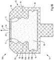
Figs. 1A and1B show a light emitting diode (LED) strip 100 (an example of the lighting device according to the first aspect) according to an exemplary embodiment.LED strip 100 includes aflexible housing 10 which extends along alength direction 70. As visible in the cross-sectional view ofFig. 1B , the flexible housing includes abase portion 11 from which twoside portions 13 extend along amain lighting direction 80 of light emitting elements, which are mounted to thebase portion 11 but not shown in the figures for conciseness purposes. Themain lighting direction 80 is for example a direction perpendicular to light emitting surfaces of LED dies mounted to thebase portion 11. -
LED strip 100 further includes a light guide 30 (an example of a light guiding structure) which extends along thelength direction 70 being arranged in betweenside portions 13 inside theflexible housing 10. It is noted that thelight guide 30 is arranged in optical contact with light emitting surfaces e.g. of LED dies arranged on thebase portion 11, which are not shown in the schematic illustration ofFigs. 1A and1B . Being arranged in this way, thelight guide 30 is arranged to receive and guide light emitted from the LED dies. - As shown in
Fig. 1B , thelight guide 30 comprises two locking protrusions 31 with respective locking features 31A, 31B, the locking protrusions 31 respectively protruding into corresponding recessedsections 19 of thecorresponding side portions 13 of theflexible housing 10 for firmly locking the light guide to theflexible housing 10. As shown, in an exemplary embodiment, thebase portion 10 and theside portions 30 at least partly surround the flexible light-guidingstructure 30. In this exemplary embodiment, each of the twoside portions 30 comprises a lockingelement 15 with corresponding locking features 15A and 15B in engagement with a corresponding locking portion of the flexible light-guidingstructure 30 for locking the flexible light-guidingstructure 30 to theflexible housing 10. -
LED strip 100 further comprises anoptical diffusor element 20 extending along thelength direction 70 opposing respective light emission portions of LEDs which are not shown in the figures.Optical diffusor element 20 is thus arranged to receive light emitted from such LED mounted to thebase portion 11. As shown,optical diffusor element 20 is received by a gap formed byupper surface 34 oflight guide 30 and the twoside portions 13 offlexible housing 10. -
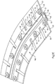
Fig. 1A further shows a mountingmember 40 which is formed as an integral component of theflexible housing 10, i.e. mountingmember 40 andflexible housing 10 are one component. In the configuration ofFig. 1 , mountingmember 40 protrudes from thebase portion 11 and extends along thelength direction 70. Mountingmember 40 further protrudes frombase portion 11 in a direction opposing main lighting direction 80 (in a depth direction). As shown, in an exemplary embodiment (in combination with all embodiments of the first aspect), the main lighting direction is essentially perpendicular to the base portion of the flexible housing. As mentioned, it turned out that such configuration of mountingmember 40 andflexible housing 10 is advantageous in particular for mountingLED strip 100 to a lamp bezel (an example of a mounting component in accordance with the second aspect). Thereby, in an exemplary embodiment of a lighting arrangement according to the second aspect, the mounting component, e.g. the lamp bezel, comprises a mounting recess and the mounting member integrally formed with the flexible housing protruding from the base portion in a direction opposing the main lighting direction is at least partially received by the mounting recess and removably or fixedly mounted to the mounting recess. - As shown in
Fig. 1A , mountingmember 40 includes mounting features 43 in form of through holes for receiving corresponding screws when mounting theLED strip 100 to a corresponding mounting component. The mounting features 43 are provided on respective mountingsections 41 which are mutually separated byrecesses 45 extending from abase section 42 and being open on one side. As explained above, recesses 45 are in particular advantageous as they suitably allow for bending of theLED strip 100, in case ofFig. 1 in particular within a plane of the mountingmember 40 when mounting theLED strip 100 to a curved portion e.g. of a Lamp bezel. - As further shown in
Fig. 1A , mountingmember 40 further comprises cut-outs 47 respectively arranged in between corresponding mountingfeature 43 and theflexible housing 10. As mentioned, such cut-outs 43 advantageously enable thermal expansion and contraction e.g. offlexible housing 10 andbase section 42 due to operation and non-operation of LEDs ofLED strip 100 while mountingsections 41 are fixed to a mounting component. A risk of damage caused by such thermal expansion and contraction is thus greatly reduced. -
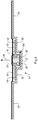
Figs. 2A to 2C show a further embodiment of an LED strip 100' (a further example of a lighting device according to the first aspect) according to an exemplary embodiment. It is noted thatflexible housing 10,optical diffusor element 20 andlight guide 30 ofFigs. 2A to 2C correspond toflexible housing 10,optical diffusor element 20 andlight guide 30 ofFigs. 1A and1B . As sown inFigs. 2A to 2C , in case of LED strip 100', two mounting members 40 (each one corresponding to mountingmember 40 ofFigs. 1A and1B ), protrude from opposingside portions 13 offlexible housing 10 and extend along the length direction of LED strip 100'. Thereby, mountingmembers 40 protrude from therespective side portions 13 in directions essentially perpendicular to main lighting direction 80 (laterally). - As mentioned, this configuration of mounting
members 40 andflexible housing 10 is advantageous in particular for mounting LED strip 100' to a vehicle body part 50 (an example of a mounting component in accordance with the second aspect) as shown inFigs. 2B and2C . The vehicle body part may for example correspond to a portion of a car body positioned such that LED strip 100' may be employed for interior or exterior illumination of a car. As can be taken fromFigs. 2B and2C ,vehicle body part 50 comprises a longitudinal mountingchannel 51 and two mountingshoulders 53 respectively arranged on corresponding sides of the longitudinal mountingchannel 51 adjacent to the longitudinal mounting channel. Each mountingmember 40 is arranged in contact with a corresponding mounting shoulder to be mounted tovehicle body part 50 e.g. using screws to be received by mountingfeatures 43. As shown inFig. 2C ,washers 63 may be used in combination with the screws to suitably distribute a mounting force of the screws and thereby adjust the mounting force to the material and geometry of the mountingmembers 40. As can further be taken fromFigs. 2B and2C , recesses 45 advantageously facilitate bending of the flexible LED strip 100' in particular within a plane of the mounting members in accordance with a shape of thevehicle body part 50. -
Figs. 2B and2C further illustrate thatflexible housing 10 of LED strip 100' is partially received by mountingchannel 51. As shown, in an exemplary embodiment, agap 65 is arranged at least in between oneside portion 13 of theflexible housing 10 and acorresponding side wall 52 of the longitudinal mountingchannel 52 and/or in between thebase portion 11 of theflexible housing 10 and a corresponding face of the longitudinal mountingchannel 51. As mentioned above, it turned out that such configuration of the flexible LED strip 100' and thevehicle body part 50 allows for a beneficial stability and mounting precision to be achieved. At the same time, providing the gap 65 (e.g. an air gap) allows for thermal expansion of the flexible housing upon operation of the LEDs, thereby reducing a risk of damage. In addition, such gap may advantageously help to compensate for different indices of thermal expansion of the LED strip 100' and thevehicle body part 50. - It is noted that a thickness of the mounting
members 40 is a suitable parameter for defining a stiffness of the portion connecting the vehicle body part and the flexible LED strip 100'. This thickness may thus be suitably adjusted e.g. to increase the stiffness of the part connecting the vehicle body part to the flexible LED strip 100' and to reduce for example an impact of vibration upon later operation. -
Fig. 3 shows a further embodiment of anLED strip 100". While in case of LED strip 100' illustrated inFigs. 2A to 2C , the mountingmembers 40 protrude from a distal end ofside portions 13, mountingmembers 40 of LED strip 100' protrude from a portion of theside portions 13 adjacent tobase portion 11. This configuration allows for an alternative mounting configuration with respect to a mounting component according to which the flexible housing may e.g. be fully received by a corresponding mounting channel of the mounting component, which is open for light to be emitted from theLED strip 100". Such configuration may provide advantages in terms of stability, mounting precision and stability. An additional advantage of this configuration may be that a light emitting area (e.g. the optical diffusor element 20) offlexible LED strip 100" is at the same vertical level as the car body part and e.g. heads of screws used for mountingLED strip 100" are hidden. -
Fig. 4 shows a further embodiment of a vehicle body part 50' which in addition to the components ofbody part 50 shown inFigs. 2B and2C includes a sealing shoulder 55' which extends from mountingshoulder 53 and allows for mounting of a sealingmember 61. Sealingmember 61 may correspond to or comprise for example a transparent protective foil, a plastic member or a glass member in combination with suitable sealing parts. The transparentprotective foil 61 may be laminated or glued on the car body part 50'. -
Fig. 5 shows a further exemplary embodiment ofLED strip 100"' (a further example of the lighting device according to the first aspect) according to a further exemplary embodiment. As compared e.g. toLED strip 100 ofFig. 1A ,LED strip 100"' comprises cut-outs 47'of larger size and different shape. While cut-outs 47 ofLED strip 100 shown inFig. 1 are advantageous for cases where a small total size of the product is desirable, cut-outs 47' are advantageous as they may even further support release of thermal stress and as they may even further support bending ofLED strip 100"'. It turned out that for example an oval or elliptical cross-section with a strong aspect ratio enables tuning such properties ofLED strip 100"'.LIST OF REFERENCE SIGNS: Lighting device 100, 100', 100". 100"' Flexible housing 10 Base portion 11 Side portion 13 Locking element 15 Inner surface 17 Recessed section 19 Optical diffusor element 20 Light-guiding structure 30 Locking protrusion 31 Locking portion 33 Upper surface Mounting member 40 Mounting section 41 Base section 42 Mounting feature 43 Recess 45 Cut- out 47, 47' Part of a vehicle body, vehicle body portion 50, 50' Mounting channel 51 Side wall 52 Mounting shoulder 53 Sealing shoulder 55' Sealing member 61 Washer 63 Air gap 65 Length direction 70 Main lighting direction 80
Claims (15)
- A lighting device (1) comprising:a flexible housing which extends along a length direction of the lighting device; andat least two light emitting elements arranged along the length direction of the lighting device and mounted to the flexible housing;wherein an inner surface of the flexible housing is configured to reflect light emitted from the at least two light emitting elements;the lighting device further comprising at least one mounting member for mounting the lighting device;wherein the at least one mounting member is an integral component of the flexible housing.
- The lighting device according to claim 1, wherein the at least one mounting member and the flexible housing are formed from a common flexible material.
- The lighting device according to any of claims 1 or 2, wherein the at least one mounting member comprises an elongated cross-section protruding outwardly from an outer surface of the flexible housing and extends along the length direction of the lighting device.
- The lighting device according to any of the preceding claims, wherein the at least one mounting member extends along at least 80% of the length of the lighting device in the length direction.
- The lighting device according to any of the preceding claims, wherein the at least one mounting member comprises at least two neighboring mounting sections, wherein each one of the at least two mounting sections is provided with at least one mounting feature for mounting the lighting device, and wherein the at least two mounting sections are mutually separated by a recess.
- The lighting device according to any of the preceding claims, further comprising at least one mounting feature for mounting the lighting device and at least one corresponding cut-out arranged in between the at least one mounting feature and the flexible housing.
- The lighting device according to any of the preceding claims, wherein the flexible housing comprises a base portion onto which the at least two light emitting elements are mounted, and two mutually opposing side portions respectively extending from the base portion, wherein the at least one mounting member protrudes from the base portion and extends along the length direction of the lighting device and/or wherein the at least one mounting member protrudes from at least one of the two side portions and extends along the length direction of the lighting device.
- The lighting device according to claim 7 further comprising a flexible light-guiding structure, which extends along the length direction of the lighting device and which is arranged inside of the flexible housing; wherein the light-guiding structure comprises at least one locking protrusion protruding into a corresponding recessed section of a corresponding one of the at least two side portions of the flexible housing for locking the light-guiding structure to the flexible housing.
- The lighting device according to any of claims 7 or 8, wherein the inner surface comprises at least respective inner surfaces of the side portions such that the flexible housing forms a mixing box for light emitted from the at least two light emitting elements.
- The lighting device according to any of the preceding claims, further comprising at least one optical diffusor element extending along the length direction of the lighting device and opposing respective light emission portions of the at least two light emitting elements.
- The lighting device according to any of the preceding claims, wherein each of the at least two light emitting elements comprises or is a light emitting diode, LED, and wherein the lighting device is a flexible LED strip.
- Lighting arrangement comprising a mounting component and the lighting device according to any of the preceding claims, wherein the at least one mounting member is removably or fixedly mounted to a corresponding portion of the mounting component.
- The lighting arrangement according to claim 12, wherein the mounting component comprises a longitudinal mounting channel and two mounting shoulders respectively arranged on corresponding sides of the longitudinal mounting channel adjacent to the longitudinal mounting channel;
wherein the lighting device comprises at least two mounting members integrally formed with the flexible housing and protruding from respective ones of the two opposing side portions of the flexible housing, each of the at least two mounting members being removably or fixedly mounted to a corresponding one of the two mounting shoulders of the mounting component;
wherein the flexible housing is at least partially received by the mounting channel. - The lighting arrangement according to any of claims 12 to 13, wherein the mounting component comprises a mounting recess;
wherein the lighting device comprises a mounting member integrally formed with the flexible housing and protruding from the base portion of the flexible housing, the mounting member being received at least partially by the mounting recess and removably or fixedly mounted to the mounting recess. - A method of manufacturing a lighting device, in particular according to any of claims 1 to 11, the method comprising:- Producing a flexible housing extending along a length direction of the lighting device; and- Arranging at least two light emitting elements along the length direction of the lighting device and mounting the at least two light emitting elements to the flexible housing;wherein the flexible housing is produced such that an inner surface of the flexible housing is configured to reflect light emitted from the at least two light emitting elements;the method further comprising:- Producing at least one mounting member for mounting the lighting device;
wherein the at least one mounting member is produced as an integral component of the flexible housing, in particular wherein the flexible housing and the at least one mounting member are produced in a single step, in particular via extrusion.
Priority Applications (3)
| Application Number | Priority Date | Filing Date | Title |
|---|---|---|---|
| EP20155269.2A EP3862620B1 (en) | 2020-02-04 | 2020-02-04 | Mechanical integration of flexible led strips |
| CN202120316785.9U CN215523153U (en) | 2020-02-04 | 2021-02-04 | Lighting device and lighting arrangement comprising such a lighting device |
| US17/167,709 US11680689B2 (en) | 2020-02-04 | 2021-02-04 | Mechanical integration of flexible LED strips |
Applications Claiming Priority (1)
| Application Number | Priority Date | Filing Date | Title |
|---|---|---|---|
| EP20155269.2A EP3862620B1 (en) | 2020-02-04 | 2020-02-04 | Mechanical integration of flexible led strips |
Publications (2)
| Publication Number | Publication Date |
|---|---|
| EP3862620A1 true EP3862620A1 (en) | 2021-08-11 |
| EP3862620B1 EP3862620B1 (en) | 2025-09-10 |
Family
ID=69468370
Family Applications (1)
| Application Number | Title | Priority Date | Filing Date |
|---|---|---|---|
| EP20155269.2A Active EP3862620B1 (en) | 2020-02-04 | 2020-02-04 | Mechanical integration of flexible led strips |
Country Status (3)
| Country | Link |
|---|---|
| US (1) | US11680689B2 (en) |
| EP (1) | EP3862620B1 (en) |
| CN (1) | CN215523153U (en) |
Families Citing this family (6)
| Publication number | Priority date | Publication date | Assignee | Title |
|---|---|---|---|---|
| GB2603482B (en) * | 2021-02-03 | 2025-10-08 | Defineline Systems Ltd | Lighting system |
| US20250116388A1 (en) * | 2022-01-31 | 2025-04-10 | Signify Holding B.V. | Lighting arrangement comprising a lens body |
| US12060985B1 (en) * | 2024-01-23 | 2024-08-13 | Sikai Chen | Bendable support for LED neon lamps |
| USD1125654S1 (en) | 2024-09-04 | 2026-05-05 | Bellson Electric Pty Ltd | LED strip light mounting track |
| USD1125653S1 (en) | 2024-09-04 | 2026-05-05 | Bellson Electric Pty Ltd | LED strip light mounting track |
| US20260063279A1 (en) * | 2024-09-04 | 2026-03-05 | Bellson Electric Pty Ltd | Adjustable track for lighting device for pools |
Citations (7)
| Publication number | Priority date | Publication date | Assignee | Title |
|---|---|---|---|---|
| US4972303A (en) * | 1989-02-06 | 1990-11-20 | Koito Manufacturing Co., Ltd. | Automobile Lamp |
| US20050213342A1 (en) * | 2004-03-29 | 2005-09-29 | Tufte Brian N | Lighting apparatus |
| US20120147610A1 (en) * | 2010-12-10 | 2012-06-14 | Multilist Sweden Ab | Device for mounting a strip of light emitting diodes |
| US20140313722A1 (en) * | 2013-04-17 | 2014-10-23 | Raw Thrills, Inc. | Flexible Decorative Lighted Strip, Cabinet Including Same, and Installation Method |
| US20150330584A1 (en) * | 2014-05-13 | 2015-11-19 | Osram Gmbh | Lighting device and corresponding mounting housing, kit and method |
| JP2016066449A (en) * | 2014-09-24 | 2016-04-28 | 大阪通商株式会社 | Light emitting device |
| CN209511752U (en) * | 2019-04-04 | 2019-10-18 | 广东雷狮光电技术有限公司 | A new type of wall washer |
Family Cites Families (6)
| Publication number | Priority date | Publication date | Assignee | Title |
|---|---|---|---|---|
| USD378857S (en) * | 1996-04-12 | 1997-04-15 | Dimex Corporation | Flexible paver restraint |
| USD541952S1 (en) * | 2005-10-06 | 2007-05-01 | Dimex Llc | Low profile paver restraint |
| US7908792B2 (en) * | 2007-02-05 | 2011-03-22 | Heighton Brent M | Edging attachment for illuminated border |
| JP6544686B2 (en) * | 2015-06-26 | 2019-07-17 | パナソニックIpマネジメント株式会社 | Optical fiber holding structure |
| US10619828B2 (en) * | 2016-11-16 | 2020-04-14 | Qtran, Inc. | Bendable LED lighting fixture |
| US10272832B2 (en) * | 2017-06-29 | 2019-04-30 | Ford Global Technologies, Llc | Lighting pipe integrated within sunroof trim ring |
-
2020
- 2020-02-04 EP EP20155269.2A patent/EP3862620B1/en active Active
-
2021
- 2021-02-04 US US17/167,709 patent/US11680689B2/en active Active
- 2021-02-04 CN CN202120316785.9U patent/CN215523153U/en active Active
Patent Citations (7)
| Publication number | Priority date | Publication date | Assignee | Title |
|---|---|---|---|---|
| US4972303A (en) * | 1989-02-06 | 1990-11-20 | Koito Manufacturing Co., Ltd. | Automobile Lamp |
| US20050213342A1 (en) * | 2004-03-29 | 2005-09-29 | Tufte Brian N | Lighting apparatus |
| US20120147610A1 (en) * | 2010-12-10 | 2012-06-14 | Multilist Sweden Ab | Device for mounting a strip of light emitting diodes |
| US20140313722A1 (en) * | 2013-04-17 | 2014-10-23 | Raw Thrills, Inc. | Flexible Decorative Lighted Strip, Cabinet Including Same, and Installation Method |
| US20150330584A1 (en) * | 2014-05-13 | 2015-11-19 | Osram Gmbh | Lighting device and corresponding mounting housing, kit and method |
| JP2016066449A (en) * | 2014-09-24 | 2016-04-28 | 大阪通商株式会社 | Light emitting device |
| CN209511752U (en) * | 2019-04-04 | 2019-10-18 | 广东雷狮光电技术有限公司 | A new type of wall washer |
Also Published As
| Publication number | Publication date |
|---|---|
| CN215523153U (en) | 2022-01-14 |
| US20210239280A1 (en) | 2021-08-05 |
| EP3862620B1 (en) | 2025-09-10 |
| US11680689B2 (en) | 2023-06-20 |
Similar Documents
| Publication | Publication Date | Title |
|---|---|---|
| EP3862620B1 (en) | Mechanical integration of flexible led strips | |
| US9494291B2 (en) | Motor vehicle lighting and/or signaling device | |
| US11530797B2 (en) | Lighting device with narrow light emitting area | |
| US20040257790A1 (en) | Luminescent indicator and vehicle rearview mirror apparatus | |
| EP2377720B1 (en) | Light guide device for automotive use | |
| US7357549B2 (en) | Vehicle lamp | |
| US10612747B2 (en) | Linear shelf light fixture with gap filler elements | |
| US9423104B2 (en) | Linear solid state lighting fixture with asymmetric light distribution | |
| EP2565084B1 (en) | Vehicle door mirror | |
| CN102498006B (en) | Shading device with integrated light guide for covering the roof of a vehicle | |
| WO2009110476A1 (en) | Illuminating device | |
| DE202013105597U1 (en) | Lamp and vehicle light equipped therewith | |
| EP1151329A4 (en) | Waveguide assembly for laterally-directed illumination in a vehicle lighting system | |
| CN107208851B (en) | Illumination lamp, cover for illumination lamp, and illumination device | |
| US11447069B2 (en) | Illumination device for a motor vehicle | |
| US8029177B2 (en) | Lighting device with at least one illuminant unit for vehicles, preferably motor vehicles | |
| US10718890B2 (en) | Optical structures with off-state appearance area | |
| CN100454111C (en) | Backlight unit capable of easily forming curves and three-dimensional shapes | |
| JP2017174622A (en) | lighting equipment | |
| US7281822B2 (en) | Outside mirror apparatus for vehicle and illuminating unit for outside mirror apparatus | |
| JP6149559B2 (en) | LED lights | |
| JP5446594B2 (en) | lighting equipment | |
| JP4947023B2 (en) | Rod-shaped light guide and light-emitting device including the same | |
| KR102164208B1 (en) | Light Source Module and Lighting Device Having the Same | |
| EP1908632B1 (en) | Lens for a lighting fixture |
Legal Events
| Date | Code | Title | Description |
|---|---|---|---|
| PUAI | Public reference made under article 153(3) epc to a published international application that has entered the european phase |
Free format text: ORIGINAL CODE: 0009012 |
|
| STAA | Information on the status of an ep patent application or granted ep patent |
Free format text: STATUS: THE APPLICATION HAS BEEN PUBLISHED |
|
| AK | Designated contracting states |
Kind code of ref document: A1 Designated state(s): AL AT BE BG CH CY CZ DE DK EE ES FI FR GB GR HR HU IE IS IT LI LT LU LV MC MK MT NL NO PL PT RO RS SE SI SK SM TR |
|
| STAA | Information on the status of an ep patent application or granted ep patent |
Free format text: STATUS: REQUEST FOR EXAMINATION WAS MADE |
|
| 17P | Request for examination filed |
Effective date: 20220207 |
|
| RBV | Designated contracting states (corrected) |
Designated state(s): AL AT BE BG CH CY CZ DE DK EE ES FI FR GB GR HR HU IE IS IT LI LT LU LV MC MK MT NL NO PL PT RO RS SE SI SK SM TR |
|
| P01 | Opt-out of the competence of the unified patent court (upc) registered |
Effective date: 20230530 |
|
| STAA | Information on the status of an ep patent application or granted ep patent |
Free format text: STATUS: EXAMINATION IS IN PROGRESS |
|
| 17Q | First examination report despatched |
Effective date: 20230712 |
|
| GRAP | Despatch of communication of intention to grant a patent |
Free format text: ORIGINAL CODE: EPIDOSNIGR1 |
|
| STAA | Information on the status of an ep patent application or granted ep patent |
Free format text: STATUS: GRANT OF PATENT IS INTENDED |
|
| RIC1 | Information provided on ipc code assigned before grant |
Ipc: F21Y 103/10 20160101ALN20250314BHEP Ipc: F21Y 115/10 20160101ALN20250314BHEP Ipc: F21V 7/00 20060101ALN20250314BHEP Ipc: F21V 15/01 20060101ALN20250314BHEP Ipc: F21V 21/00 20060101ALI20250314BHEP Ipc: F21S 4/24 20160101AFI20250314BHEP |
|
| INTG | Intention to grant announced |
Effective date: 20250402 |
|
| RIN1 | Information on inventor provided before grant (corrected) |
Inventor name: KLEIJNEN, CHRISTIAN Inventor name: MERTENS, JUERGEN Inventor name: MONESTIER, FLORENT GREGOIRE |
|
| GRAS | Grant fee paid |
Free format text: ORIGINAL CODE: EPIDOSNIGR3 |
|
| GRAA | (expected) grant |
Free format text: ORIGINAL CODE: 0009210 |
|
| STAA | Information on the status of an ep patent application or granted ep patent |
Free format text: STATUS: THE PATENT HAS BEEN GRANTED |
|
| AK | Designated contracting states |
Kind code of ref document: B1 Designated state(s): AL AT BE BG CH CY CZ DE DK EE ES FI FR GB GR HR HU IE IS IT LI LT LU LV MC MK MT NL NO PL PT RO RS SE SI SK SM TR |
|
| REG | Reference to a national code |
Ref country code: GB Ref legal event code: FG4D |
|
| REG | Reference to a national code |
Ref country code: CH Ref legal event code: EP |
|
| REG | Reference to a national code |
Ref country code: DE Ref legal event code: R096 Ref document number: 602020058366 Country of ref document: DE |
|
| REG | Reference to a national code |
Ref country code: IE Ref legal event code: FG4D |
|
| PG25 | Lapsed in a contracting state [announced via postgrant information from national office to epo] |
Ref country code: NO Free format text: LAPSE BECAUSE OF FAILURE TO SUBMIT A TRANSLATION OF THE DESCRIPTION OR TO PAY THE FEE WITHIN THE PRESCRIBED TIME-LIMIT Effective date: 20251210 |
|
| REG | Reference to a national code |
Ref country code: LT Ref legal event code: MG9D |
|
| PG25 | Lapsed in a contracting state [announced via postgrant information from national office to epo] |
Ref country code: FI Free format text: LAPSE BECAUSE OF FAILURE TO SUBMIT A TRANSLATION OF THE DESCRIPTION OR TO PAY THE FEE WITHIN THE PRESCRIBED TIME-LIMIT Effective date: 20250910 |
|
| REG | Reference to a national code |
Ref country code: NL Ref legal event code: MP Effective date: 20250910 |
|
| PG25 | Lapsed in a contracting state [announced via postgrant information from national office to epo] |
Ref country code: HR Free format text: LAPSE BECAUSE OF FAILURE TO SUBMIT A TRANSLATION OF THE DESCRIPTION OR TO PAY THE FEE WITHIN THE PRESCRIBED TIME-LIMIT Effective date: 20250910 |
|
| PG25 | Lapsed in a contracting state [announced via postgrant information from national office to epo] |
Ref country code: GR Free format text: LAPSE BECAUSE OF FAILURE TO SUBMIT A TRANSLATION OF THE DESCRIPTION OR TO PAY THE FEE WITHIN THE PRESCRIBED TIME-LIMIT Effective date: 20251211 |
|
| PG25 | Lapsed in a contracting state [announced via postgrant information from national office to epo] |
Ref country code: SE Free format text: LAPSE BECAUSE OF FAILURE TO SUBMIT A TRANSLATION OF THE DESCRIPTION OR TO PAY THE FEE WITHIN THE PRESCRIBED TIME-LIMIT Effective date: 20250910 |
|
| PG25 | Lapsed in a contracting state [announced via postgrant information from national office to epo] |
Ref country code: LV Free format text: LAPSE BECAUSE OF FAILURE TO SUBMIT A TRANSLATION OF THE DESCRIPTION OR TO PAY THE FEE WITHIN THE PRESCRIBED TIME-LIMIT Effective date: 20250910 |
|
| PG25 | Lapsed in a contracting state [announced via postgrant information from national office to epo] |
Ref country code: BG Free format text: LAPSE BECAUSE OF FAILURE TO SUBMIT A TRANSLATION OF THE DESCRIPTION OR TO PAY THE FEE WITHIN THE PRESCRIBED TIME-LIMIT Effective date: 20250910 Ref country code: PL Free format text: LAPSE BECAUSE OF FAILURE TO SUBMIT A TRANSLATION OF THE DESCRIPTION OR TO PAY THE FEE WITHIN THE PRESCRIBED TIME-LIMIT Effective date: 20250910 |
|
| PG25 | Lapsed in a contracting state [announced via postgrant information from national office to epo] |
Ref country code: RS Free format text: LAPSE BECAUSE OF FAILURE TO SUBMIT A TRANSLATION OF THE DESCRIPTION OR TO PAY THE FEE WITHIN THE PRESCRIBED TIME-LIMIT Effective date: 20251210 |
|
| PG25 | Lapsed in a contracting state [announced via postgrant information from national office to epo] |
Ref country code: ES Free format text: LAPSE BECAUSE OF FAILURE TO SUBMIT A TRANSLATION OF THE DESCRIPTION OR TO PAY THE FEE WITHIN THE PRESCRIBED TIME-LIMIT Effective date: 20250910 |
|
| REG | Reference to a national code |
Ref country code: AT Ref legal event code: MK05 Ref document number: 1836223 Country of ref document: AT Kind code of ref document: T Effective date: 20250910 |
|
| PG25 | Lapsed in a contracting state [announced via postgrant information from national office to epo] |
Ref country code: NL Free format text: LAPSE BECAUSE OF FAILURE TO SUBMIT A TRANSLATION OF THE DESCRIPTION OR TO PAY THE FEE WITHIN THE PRESCRIBED TIME-LIMIT Effective date: 20250910 |
|
| PG25 | Lapsed in a contracting state [announced via postgrant information from national office to epo] |
Ref country code: SM Free format text: LAPSE BECAUSE OF FAILURE TO SUBMIT A TRANSLATION OF THE DESCRIPTION OR TO PAY THE FEE WITHIN THE PRESCRIBED TIME-LIMIT Effective date: 20250910 |
|
| PGFP | Annual fee paid to national office [announced via postgrant information from national office to epo] |
Ref country code: GB Payment date: 20260223 Year of fee payment: 7 |
|
| PGFP | Annual fee paid to national office [announced via postgrant information from national office to epo] |
Ref country code: DE Payment date: 20260220 Year of fee payment: 7 |
|
| PG25 | Lapsed in a contracting state [announced via postgrant information from national office to epo] |
Ref country code: AT Free format text: LAPSE BECAUSE OF FAILURE TO SUBMIT A TRANSLATION OF THE DESCRIPTION OR TO PAY THE FEE WITHIN THE PRESCRIBED TIME-LIMIT Effective date: 20250910 |
|
| PG25 | Lapsed in a contracting state [announced via postgrant information from national office to epo] |
Ref country code: IT Free format text: LAPSE BECAUSE OF FAILURE TO SUBMIT A TRANSLATION OF THE DESCRIPTION OR TO PAY THE FEE WITHIN THE PRESCRIBED TIME-LIMIT Effective date: 20250910 |
|
| PG25 | Lapsed in a contracting state [announced via postgrant information from national office to epo] |
Ref country code: IS Free format text: LAPSE BECAUSE OF FAILURE TO SUBMIT A TRANSLATION OF THE DESCRIPTION OR TO PAY THE FEE WITHIN THE PRESCRIBED TIME-LIMIT Effective date: 20260110 |
|
| PGFP | Annual fee paid to national office [announced via postgrant information from national office to epo] |
Ref country code: FR Payment date: 20260224 Year of fee payment: 7 |
|
| PG25 | Lapsed in a contracting state [announced via postgrant information from national office to epo] |
Ref country code: PT Free format text: LAPSE BECAUSE OF FAILURE TO SUBMIT A TRANSLATION OF THE DESCRIPTION OR TO PAY THE FEE WITHIN THE PRESCRIBED TIME-LIMIT Effective date: 20260112 Ref country code: CZ Free format text: LAPSE BECAUSE OF FAILURE TO SUBMIT A TRANSLATION OF THE DESCRIPTION OR TO PAY THE FEE WITHIN THE PRESCRIBED TIME-LIMIT Effective date: 20250910 |
|
| PG25 | Lapsed in a contracting state [announced via postgrant information from national office to epo] |
Ref country code: EE Free format text: LAPSE BECAUSE OF FAILURE TO SUBMIT A TRANSLATION OF THE DESCRIPTION OR TO PAY THE FEE WITHIN THE PRESCRIBED TIME-LIMIT Effective date: 20250910 Ref country code: SK Free format text: LAPSE BECAUSE OF FAILURE TO SUBMIT A TRANSLATION OF THE DESCRIPTION OR TO PAY THE FEE WITHIN THE PRESCRIBED TIME-LIMIT Effective date: 20250910 |