EP3862617A1 - Vorrichtung zur sicherung eines gefahrenbereichs - Google Patents
Vorrichtung zur sicherung eines gefahrenbereichs Download PDFInfo
- Publication number
- EP3862617A1 EP3862617A1 EP20186107.7A EP20186107A EP3862617A1 EP 3862617 A1 EP3862617 A1 EP 3862617A1 EP 20186107 A EP20186107 A EP 20186107A EP 3862617 A1 EP3862617 A1 EP 3862617A1
- Authority
- EP
- European Patent Office
- Prior art keywords
- protective field
- optical sensor
- control signal
- specified
- sensor
- Prior art date
- Legal status (The legal status is an assumption and is not a legal conclusion. Google has not performed a legal analysis and makes no representation as to the accuracy of the status listed.)
- Granted
Links
Images


Classifications
-
- F—MECHANICAL ENGINEERING; LIGHTING; HEATING; WEAPONS; BLASTING
- F16—ENGINEERING ELEMENTS AND UNITS; GENERAL MEASURES FOR PRODUCING AND MAINTAINING EFFECTIVE FUNCTIONING OF MACHINES OR INSTALLATIONS; THERMAL INSULATION IN GENERAL
- F16P—SAFETY DEVICES IN GENERAL; SAFETY DEVICES FOR PRESSES
- F16P3/00—Safety devices acting in conjunction with the control or operation of a machine; Control arrangements requiring the simultaneous use of two or more parts of the body
- F16P3/12—Safety devices acting in conjunction with the control or operation of a machine; Control arrangements requiring the simultaneous use of two or more parts of the body with means, e.g. feelers, which in case of the presence of a body part of a person in or near the danger zone influence the control or operation of the machine
- F16P3/14—Safety devices acting in conjunction with the control or operation of a machine; Control arrangements requiring the simultaneous use of two or more parts of the body with means, e.g. feelers, which in case of the presence of a body part of a person in or near the danger zone influence the control or operation of the machine the means being photocells or other devices sensitive without mechanical contact
- F16P3/142—Safety devices acting in conjunction with the control or operation of a machine; Control arrangements requiring the simultaneous use of two or more parts of the body with means, e.g. feelers, which in case of the presence of a body part of a person in or near the danger zone influence the control or operation of the machine the means being photocells or other devices sensitive without mechanical contact using image capturing devices
-
- F—MECHANICAL ENGINEERING; LIGHTING; HEATING; WEAPONS; BLASTING
- F16—ENGINEERING ELEMENTS AND UNITS; GENERAL MEASURES FOR PRODUCING AND MAINTAINING EFFECTIVE FUNCTIONING OF MACHINES OR INSTALLATIONS; THERMAL INSULATION IN GENERAL
- F16P—SAFETY DEVICES IN GENERAL; SAFETY DEVICES FOR PRESSES
- F16P3/00—Safety devices acting in conjunction with the control or operation of a machine; Control arrangements requiring the simultaneous use of two or more parts of the body
- F16P3/12—Safety devices acting in conjunction with the control or operation of a machine; Control arrangements requiring the simultaneous use of two or more parts of the body with means, e.g. feelers, which in case of the presence of a body part of a person in or near the danger zone influence the control or operation of the machine
- F16P3/14—Safety devices acting in conjunction with the control or operation of a machine; Control arrangements requiring the simultaneous use of two or more parts of the body with means, e.g. feelers, which in case of the presence of a body part of a person in or near the danger zone influence the control or operation of the machine the means being photocells or other devices sensitive without mechanical contact
- F16P3/144—Safety devices acting in conjunction with the control or operation of a machine; Control arrangements requiring the simultaneous use of two or more parts of the body with means, e.g. feelers, which in case of the presence of a body part of a person in or near the danger zone influence the control or operation of the machine the means being photocells or other devices sensitive without mechanical contact using light grids
Definitions
- the invention relates to a device for securing a danger area.
- Devices of this type can be provided to secure danger areas on stationary machines or systems, where a danger area in which dangerous movements are carried out by the machine or system is to be safeguarded.
- Such devices can be used to secure the area in front of vehicles in order to implement collision protection for the vehicle.
- distance-measuring optical sensors for monitoring hazardous areas, it being possible for them to be designed, for example, as area distance sensors, that is to say as scanning distance sensors.
- a binary switching signal with a corresponding switching state is generated. If the switching signal assumes the switching state "Object present" when an object is detected, a safety function is triggered, whereby a safe operating condition is brought about, which avoids endangering persons.
- the safety function can consist of shutting down the machine or system.
- the safety function may consist of stopping the vehicle.
- the invention is based on the object of providing a device of the type mentioned at the outset, by means of which an improved safeguarding of danger areas is made possible.
- the invention relates to a device for securing a danger area, with at least one distance-measuring optical sensor which is designed for object detection in a flat or spatial detection area.
- the optical sensor is used to monitor objects within at least one predetermined protective field.
- Object monitoring in the specified protective field can be deactivated by means of a control signal.
- at least one new protective field is generated, within which the optical sensor continues the object monitoring.
- the new protective field is deactivated for a specified activation time. After the activation time has elapsed, the optical sensor carries out object monitoring again within the specified protective field.
- the basic idea of the invention is therefore to use the control signal to specifically change the object monitoring carried out with the optical sensor and to adapt it to changing boundary conditions.
- the control signal read into the optical sensor by an external unit can in particular be a malfunction signaling, for example a process malfunction of a system to be monitored.
- the monitoring function of the device according to the invention is generally designed in such a way that a switching signal is generated in the optical sensor, the switching states of which indicate whether an object is located in the protective field or not.
- a switching signal signaling an object in the protective field is used to trigger a safety function.
- the safety function can consist in the fact that a system monitored by the optical sensor, which could pose a risk to people, is shut down.
- object monitoring is carried out in a predetermined protective field during regular operation.
- safety-critical objects are detected in the protective field, such object detection leading to the generation of a switching signal and, depending on this, to the triggering of a safety function.
- the specified protective field is dimensioned in such a way that permitted objects that do not lead to hazards do not penetrate the specified protective field.
- the optical sensor is used to monitor a danger area on a conveyor unit on which conveyed goods are fed to the system.
- the conveyed goods represent permissible objects that do not lead to hazards.
- control signal is generated by the control of the conveyor unit.
- the specified protective field is then dimensioned in such a way that the conveyed goods do not protrude into this specified protective field.
- the specified protective field is adapted to the maximum size of the conveyed goods.
- control signal is activated and the object monitoring is deactivated within the specified protective field, then the state of the current object monitoring in the specified protective field is used.
- the optical sensor If an object intrusion is currently registered in the specified protective field, the optical sensor generates the switching signal that leads to the generation of the safety function.
- the new protective field can in principle be smaller than the specified protective field, but this is advantageously larger.
- the new protective field is dimensioned in such a way that the object in the danger area does not protrude into the new protective field and is thus treated as a permissible object.
- the contour of the object present in the danger area is advantageously taught in as a reference contour.
- the limit of the new protective field is determined depending on the reference contour.
- control of the conveyor unit can generate the control signal, for example, if the conveyor unit is stopped due to a fault or the like.
- a permissible object that is, a conveyed item
- the new protective field is adapted to this permissible object in such a way that the permissible object is left out of the new protective field, this does not lead to an unnecessary generation of a switching signal and thus also to an unnecessary triggering of the safety function.
- the new protective field is activated for a predetermined activation time. After the activation time has elapsed, the optical sensor carries out object monitoring again within the specified protective field.
- a change in the operating mode of the optical sensor is therefore only carried out temporarily with the control signal, advantageously only as long as a fault which leads to the resolution of the control signal is present.
- the activation time expediently corresponds to the duration of the activation of the control signal.
- the control signal thus directly specifies the activation time.
- the optical sensor is a surface distance sensor or a camera sensor.
- the optical sensor is also advantageously a safety sensor.
- the optical sensor and also the entire device can thus be used in the field of security technology, in particular in the field of personal protection.
- the optical sensor designed as a safety sensor has a fail-safe structure for this purpose. This is advantageously achieved in that the optical sensor has a redundant evaluation unit, in particular in the form of two computer units that monitor each other cyclically.
- the device according to the invention has a multiple arrangement of optical sensors.
- One or more protective fields can be monitored with an optical sensor.
- the Figures 1 to 3 show exemplary embodiments of distance-measuring optical sensors 1, the distance measurements advantageously taking place according to a pulse time-of-flight method or a phase measuring method.
- Figure 1 shows an exemplary embodiment of an optical sensor 1 in the form of a surface distance sensor, that is to say a scanning distance sensor.
- the optical sensor 1 has a transmitter 3 which emits light beams 2 and a receiver 4 which receives light beams 2.
- the transmitter 3 emits light beams 2 in the form of light pulses.
- the light beams 2 are reflected on an object 5 to be detected, the corresponding time of flight of the light pulses to the object 5 and back to the optical sensor 1 being evaluated for the distance determinations.
- the sensor components of the optical sensors 1 are integrated in a housing 6, the transmitter 3 and the receiver 4 with a upstream receiving optics 7 are arranged stationary in the housing 6.
- the deflection unit 8 is motor-driven and comprises an angular mirror 9 which can be rotated about an axis of rotation D and on which the light beams 2 are deflected.
- Figure 2 shows a variant of the surface distance sensor according to Figure 1 .
- the periodic deflection of the light beams 2 takes place in that the transmitter 3 and the receiver 4 are arranged in a measuring head 10 which can be rotated about an axis of rotation D, the measuring head 10 being rotatably mounted on a base 11.
- Figure 3 shows the sensor components of an optical sensor 1 configured as a camera sensor can.
- each optical sensor 1 has an evaluation unit (not shown) in which the received signals from the receiver 4 are evaluated.
- the evaluation is carried out in such a way that protective field monitoring is carried out and a binary switching signal is generated depending on an object intrusion in a protective field, the switching states of which indicate whether an object 5 is present in protective field 20 or not. If an object 5 is present in protective field 20, the corresponding switching state of the switching signal triggers a safety function in such a way that a dangerous machine is shut down so that it can no longer pose any dangers.
- the optical sensors 1 are according to Figures 1 to 3 designed as a safety sensor and have a fail-safe structure, which could be implemented, for example, by a redundant evaluation unit in the form of two computer units that monitor each other cyclically.
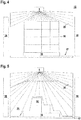
- the Figures 4 and 5 show a first exemplary embodiment of the device 15 according to the invention, in which an optical sensor 1 according to FIGS. 1 to 3 is generally used, the optical sensor 1 being designed as a surface distance sensor in the present case.
- the device 15 is used to secure access to a dangerous machine (not shown). In order to be able to carry out work processes with the machine, this conveyed material 16 must be supplied.
- a conveyor unit in the form of a conveyor belt 17 is provided, which is laterally protected by fences 18.
- the conveyed material 16 is conveyed on the conveyor belt 17 lying on pallets 19.
- the conveyor belt 17 is controlled with a controller, not shown. In regular operation, the conveyor belt 17 is moved via the controller at its predetermined, preferably constant, speed.
- the optical sensor 1 is arranged above the conveyor belt 17. In regular operation, protective field monitoring is monitored with the optical sensor 1 within a predetermined protective field 20, which is oriented in the vertical direction and thus perpendicular to the surface of the conveyor belt 17.
- the specified protective field 20 is based on the maximum size of the conveyed goods, shown in Figure 4 , customized. This ensures that all conveyed goods can pass the optical sensor 1 and be fed to the machine as non-dangerous, permissible objects 5 without violating the specified protective field 20 and therefore without triggering the safety function. An additional penetration of security-critical objects 5, in particular people, on the other hand leads to a protective field violation and the triggering of the safety function.
- a control signal is generated in the controller, which is read into the optical sensor 1.
- Figure 5 shows, in the optical sensor 1, a new protective field 21 generated as an extension of the predetermined protective field 20 by a teaching process.
- the new protective field 21 is also oriented in the vertical direction.
- the contour of the conveyed material 16 currently present in the receiving area of the optical sensor 1 is detected as a permissible object 5 as with the optical sensor 1 and is stored as a reference contour.
- the new protective field 21 imaged therefrom represents an extension of the predefined protective field 20 in such a way that with the new protective field 21, the conveyed goods 16 present in the detection area of the optical sensor 1 are exactly left out.
- the object monitoring within the specified protective field 20 is deactivated in the optical sensor 1 and object monitoring is thus carried out in the new protective field 21.
- This new object monitoring takes place only temporarily during a specified activation time.
- the activation time advantageously corresponds to the time period during which the control signal is activated, that is to say for the time period of the stop in delivery.
- the new protective field 21 is adapted to the contour of the conveyed material 16 present in the detection area of the optical sensor 1, it does not protrude into the new protective field 21 and does not lead to an unnecessary triggering of the safety function.
- the optical sensor 1 After the activation time has elapsed, the optical sensor 1 returns to an old monitoring mode, that is, monitoring takes place again within the specified protective field 20.
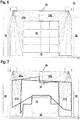
- Figures 6 and 7 show a variant of the embodiment of Figures 4 and 5 .
- two optical sensors 1 are provided.
- the optical sensors 1 monitor two specified partial protective fields 20a, b, which complement each other to form the specified protective field 20 ( Figure 6 ). If the control signal is activated, new partial protective fields 21a, b are determined for the two optical sensors 1, which supplement each other to form the new protective fields 21, in which the currently available conveyed goods 16 are again adapted ( Figure 7 ).
- the switching signals generated in the optical sensors 1, which report object intrusions in the individual partial protection fields, are brought together, preferably logically linked, in a higher-level evaluation unit (not shown).
- the machine is then controlled with the switching signal thus obtained, in particular the safety function is triggered. Otherwise, the monitoring takes place in accordance with the embodiment of Figures 4 and 5 .
Landscapes
- Engineering & Computer Science (AREA)
- General Engineering & Computer Science (AREA)
- Mechanical Engineering (AREA)
- Geophysics And Detection Of Objects (AREA)
Abstract
Description
- Die Erfindung betrifft eine Vorrichtung zur Sicherung eines Gefahrenbereichs.
- Derartige Vorrichtungen können zur Sicherung von Gefahrenbereichen an stationären Maschinen oder Anlagen vorgesehen sein, wobei dort ein Gefahrenbereich, in welchem von der Maschine oder Anlage gefahrbringende Bewegungen ausgeführt werden, abzusichern ist.
- Weiterhin können derartige Vorrichtungen zur Sicherung des Vorfelds an Fahrzeugen eingesetzt werden, um einen Kollisionsschutz für das Fahrzeug zu realisieren.
- In beiden Fällen ist es bekannt, distanzmessende optische Sensoren zur Überwachung von Gefahrenbereichen einzusetzen, wobei diese beispielsweise als Flächendistanzsensor, das heißt als scannende Distanzsensoren, ausgebildet sein können.
- Zur Anpassung an verschiedene beziehungsweise sich ändernde Gefahrenbereiche ist es bekannt, dass im optischen Sensor unterschiedliche Schutzfelder gespeichert sind. Je nach Gefahrensituation wird im optischen Sensor ein Schutzfeld aktiviert, sodass innerhalb dieses vorgegebenen Schutzfelds eine Objektüberwachung erfolgt.
- Im optischen Sensor wird dann abhängig davon, ob im vorgegebenen Schutzfeld ein Objekt detektiert wird, ein binäres Schaltsignal mit einem entsprechenden Schaltzustand erzeugt. Nimmt das Schaltsignal bei einer Objektdetektion den Schaltzustand "Objekt vorhanden" ein, wird eine Sicherheitsfunktion ausgelöst, wodurch ein sicherer Betriebszustand herbeigeführt wird, der Gefährdungen von Personen vermeidet. Bei der Überwachung einer gefahrbringenden stationären Maschine oder Anlage kann die Sicherheitsfunktion darin bestehen, die Maschine oder Anlage stillzusetzen. Bei der Überwachung eines Fahrzeugs kann die Sicherheitsfunktion darin bestehen, das Fahrzeug anzuhalten.
- Der Erfindung liegt die Aufgabe zugrunde eine Vorrichtung der eingangsgenannten Art bereitzustellen, mittels derer eine verbesserte Sicherung von Gefahrenbereichen ermöglicht wird.
- Zur Lösung dieser Aufgabe sind die Merkmale des Anspruchs 1 vorgesehen.
- Die Erfindung betrifft eine Vorrichtung zur Sicherung eines Gefahrenbereichs, mit wenigstens einem distanzmessenden optischen Sensor, der für eine Objekterfassung in einem flächigen oder räumlichen Erfassungsbereich ausgebildet ist. Zur Absicherung des Gefahrenbereichs wird mit dem optischen Sensor eine Objektüberwachung innerhalb wenigstens eines vorgegebenen Schutzfelds durchgeführt. Mittels eines Steuersignals ist die Objektüberwachung im vorgegebenen Schutzfeld deaktivierbar. Abhängig von einem im Gefahrenbereich vorhandenen Objekt wird wenigstens ein neues Schutzfeld generiert, innerhalb dessen der optische Sensor die Objektüberwachung weiterführt. Das neue Schutzfeld ist für eine vorgegebene Aktivierungszeit deaktiviert. Nach Ablauf der Aktivierungszeit führt der optische Sensor wieder die Objektüberwachung innerhalb des vorgegebenen Schutzfelds durch.
- Der Grundgedanke der Erfindung besteht somit darin, mit dem Steuersignal gezielt die mit dem optischen Sensor durchgeführte Objektüberwachung zu verändern und an sich ändernde Randbedingungen anzupassen.
- Das von einer externen Einheit in den optischen Sensor eingelesene Steuersignal kann insbesondere eine Störung signalisierende, beispielsweise Ablaufstörung einer zu überwachenden Anlage sein.
- Die Überwachungsfunktion der erfindungsgemäßen Vorrichtung ist generell derart ausgebildet, dass im optischen Sensor ein Schaltsignal generiert wird, dessen Schaltzustände angeben, ob sich ein Objekt im Schutzfeld befindet oder nicht.
- Dabei wird mit einem ein Objekt im Schutzfeld signalisierenden Schaltsignal eine Sicherheitsfunktion ausgelöst.
- Die Sicherheitsfunktion kann darin bestehen, dass eine mit dem optischen Sensor überwachte Anlage von der Gefährdungen für Personen ausgehen können, stillgesetzt wird.
- Bei der erfindungsgemäßen Vorrichtung wird im regulären Betrieb eine Objektüberwachung in einem vorgegebenen Schutzfeld durchgeführt. Damit werden sicherheitskritische Objekte im Schutzfeld erfasst, wobei eine solche Objekterfassung zur Generierung eines Schaltsignals und abhängig hiervon zur Auslösung einer Sicherheitsfunktion führt.
- Das vorgegebene Schutzfeld ist dabei so dimensioniert, dass zulässige Objekte, die nicht zu Gefährdungen führen, nicht in das vorgegebene Schutzfeld eindringen.
- Ein Beispiel hierfür ist eine Zugangssicherung zur Absicherung eines Zugangs zu einer gefahrbringenden Anlage. Insbesondere wird dann mit dem optischen Sensor ein Gefahrenbereich an einer Fördereinheit überwacht, auf welcher Fördergüter der Anlage zugeführt werden. Die Fördergüter stellen zulässige Objekte dar, die nicht zu Gefährdungen führen.
- In diesem Fall wird das Steuersignal von der Steuerung der Fördereinheit generiert.
- Das vorgegebene Schutzfeld ist dann so dimensioniert, dass die Fördergüter nicht in dieses vorgegebene Schutzfeld ragen. Hierzu ist das vorgegebene Schutzfeld an die maximale Größe der Fördergüter angepasst.
- Wird erfindungsgemäß das Steuersignal aktiviert und dadurch die Objektüberwachung innerhalb des vorgegebenen Schutzfelds deaktiviert, so wird dabei der Zustand der aktuellen Objektüberwachung im vorgegebenen Schutzfeld ausgenutzt.
- Wird aktuell ein Objekteingriff im vorgegebenen Schutzfeld registriert, generiert der optische Sensor das Schaltsignal, das zur Generierung der Sicherheitsfunktion führt.
- Wird dagegen im optischen Sensor kein Objekt im vorgegebenen Schutzfeld erkannt, kann im Erfassungsbereich dieses optischen Sensors nur ein zulässiges Objekt außerhalb des vorgegebenen Schutzfelds angeordnet sein.
- Dieses Vorwissen wird für die erfindungsgemäße Betriebsartänderung bei Vorlegen des Steuersignals ausgenutzt. Da nur ein zulässiges Objekt im Erfassungsbereich des optischen Sensors liegen kann, wird abhängig von diesem ein neues Schutzfeld generiert.
- Das neue Schutzfeld kann prinzipiell kleiner sein als das vorgegebene Schutzfeld, vorteilhaft ist dieses jedoch größer.
- Generell wird das neue Schutzfeld so dimensioniert, dass das im Gefahrenbereich vorhandene Objekt nicht in das neue Schutzfeld ragt, und somit als zulässiges Objekt behandelt wird. Vorteilhaft wird hierzu bei Aktivieren des Steuersignals mittels des optischen Sensors die Kontur des im Gefahrenbereich vorhandenen Objekts als Referenzkontur eingelernt. Abhängig von der Referenzkontur wird die Grenze des neuen Schutzfelds bestimmt.
- Damit ist auf einfache und sichere Weise eine Unterscheidung dieses zulässigen Objekts von gefahrbringenden, sicherheitskritischen Objekten möglich, da nur die sicherheitskritischen Objekte zu einem Eingriff in das neue Schutzfeld führen, nicht jedoch das zuvor eingelernte zulässige Objekt, an welches die Größe des neuen Schutzfelds angepasst ist.
- Für den Fall, dass mit dem optischen Sensor ein Gefahrenbereich an einer Fördereinheit überwacht wird, kann beispielsweise die Steuerung der Fördereinheit das Steuersignal generieren, wenn die Fördereinheit aufgrund einer Störung oder dergleichen angehalten wird.
- In diesem Fall kann gerade ein zulässiges Objekt, das heißt ein Fördergut, im Gefahrenbereich vorhanden sein. Da bei Generierung des Steuersignals das neue Schutzfeld an dieses zulässige Objekt so angepasst ist, dass das zulässige Objekt vom neuen Schutzfeld ausgespart ist, führt dieses nicht zu einer unnötigen Generierung eines Schaltsignals und damit auch nicht zu einer unnötigen Auslösung der Sicherheitsfunktion.
- Dringt dagegen ein nicht zulässiges Objekt in den Gefahrenbereich ein, wird dieses auf jeden Fall im neuen Schutzfeld erkannt, da das neue Schutzfeld an die Kontur des zulässigen Objekts angepasst ist, und das zusätzliche nicht zulässige Objekt zwangsläufig zu einer Schutzfeldverletzung führt. Damit wird im optischen Sensor ein Schaltsignal generiert, das zur Auslösung der Sicherheitsfunktion führt, sodass eine sichere Erfassung von sicherheitskritischen Objekten gewährleistet ist.
- Erfindungsgemäß ist das neue Schutzfeld für eine vorgegebene Aktivierungszeit aktiviert. Nach Ablauf der Aktivierungszeit führt der optische Sensor wieder die Objektüberwachung innerhalb des vorgegebenen Schutzfelds durch.
- Mit dem Steuersignal wird somit nur temporär eine Betriebsartänderung des optischen Sensors durchgeführt, vorteilhaft nur so lange wie ein Störfall, der zur Auflösung des Steuersignals führt, vorhanden ist.
- Zweckmäßig entspricht die Aktivierungszeit der Zeitdauer der Aktivierung des Steuersignals.
- Damit gibt das Steuersignal unmittelbar die Aktivierungszeit vor.
- Gemäß einer vorteilhaften Ausführungsform ist der optische Sensor ein Flächendistanzsensor oder ein Kamerasensor.
- Weiter vorteilhaft ist der optische Sensor ein Sicherheitssensor.
- Damit kann der optische Sensor und auch die gesamte Vorrichtung im Bereich der Sicherheitstechnik, insbesondere im Bereich des Personenschutzes eingesetzt werden. Der als Sicherheitssensor ausgebildete optische Sensor weist hierzu einen fehlersicheren Aufbau auf. Dies wird vorteilhaft dadurch erreicht, dass der optische Sensor eine redundante Auswerteeinheit aufweist, insbesondere in Form zweier sich zyklisch überwachender Rechnereinheiten.
- Gemäß einer vorteilhaften Weiterbildung weist die erfindungsgemäße Vorrichtung eine Mehrfachanordnung von optischen Sensoren auf.
- Dabei kann mit einem optischen Sensor ein oder mehrere Schutzfelder überwacht werden.
- Die Erfindung wird im Folgenden anhand der Zeichnungen erläutert. Es zeigen:
- Figur 1:
- Erstes Ausführungsbeispiel eines optischen Sensors.
- Figur 2:
- Zweites Ausführungsbeispiel eines optischen Sensors.
- Figur 3:
- Drittes Ausführungsbeispiel eines optischen Sensors.
- Figur 4:
- Erstes Ausführungsbeispiel der erfindungsgemäßen Vorrichtung mit einem optischen Sensor bei einer Objektüberwachung innerhalb eines vorgegebenen Schutzfeldes.
- Figur 5:
- Anordnung gemäß
Figur 4 bei einer Objektüberwachung innerhalb eines temporären neuen Schutzfelds. - Figur 6:
- Zweites Ausführungsbeispiel der erfindungsgemäßen Vorrichtung mit zwei optischen Sensoren bei einer Objektüberwachung innerhalb vorgegebener Schutzfelder.
- Figur 7:
- Anordnung gemäß
Figur 6 bei einer Objektüberwachung innerhalb temporärer neuer Schutzfelder. - Die
Figuren 1 bis 3 zeigen Ausführungsbeispiele von distanzmessenden optischen Sensoren 1, wobei die Distanzmessungen vorteilhaft nach einem Impuls-Laufzeitverfahren oder einem Phasenmessverfahren erfolgen. -
Figur 1 zeigt ein Ausführungsbeispiel eines optischen Sensors 1 in Form eines Flächendistanzsensors, das heißt eines scannendes Distanzsensors. Zur Durchführung von Distanzmessungen weist der optische Sensor 1 einen Lichtstrahlen 2 emittierenden Sender 3 und einen Lichtstrahlen 2 empfangenden Empfänger 4 auf. Der Sender 3 emittiert Lichtstrahlen 2 in Form von Lichtimpulsen. Wie Figur 1 zeigt, werden die Lichtstrahlen 2 an einem zu detektierenden Objekt 5 reflektiert, wobei die entsprechende Lichtlaufzeit der Lichtimpulse zum Objekt 5 und zurück zum optischen Sensor 1 für die Distanzbestimmungen ausgewertet werden. - Wie
Figur 1 zeigt, sind die Sensorkomponenten der optischen Sensoren 1 in einem Gehäuse 6 integriert, wobei der Sender 3 sowie der Empfänger 4 mit einer vorgeordneten Empfangsoptik 7 stationär im Gehäuse 6 angeordnet sind. Mit dem optischen Sensor 1 erfolgt eine Objektdetektion in einem flächigen Erfassungsbereich dadurch, dass die Lichtstrahlen 2 mittels einer Ablenkeinheit 8 periodisch abgelenkt werden. Die Ablenkeinheit 8 ist motorisch angetrieben und umfasst einen um eine Drehachse D drehbaren Winkelspiegel 9, an dem die Lichtstrahlen 2 abgelenkt werden. -
Figur 2 zeigt eine Variante des Flächendistanzsensors gemäßFigur 1 . In diesem Fall erfolgt die periodische Ablenkung der Lichtstrahlen 2 dadurch, dass der Sender 3 und der Empfänger 4 in einem um eine Drehachse D drehbaren Messkopf 10 angeordnet sind, wobei der Messkopf 10 auf einem Sockel 11 drehbar gelagert ist. -
Figur 3 zeigt die Sensorkomponenten eines als Kamerasensor ausgebildeten optischen Sensors 1. Dieser optische Sensor 1 weist eine Lichtstrahlen 2 emittierende Beleuchtungseinheit 12 und als Empfänger 4 einen Bildsensor 13 auf, der in Form eines CCD- oder CMOS-Arrays mit einer matrixförmigen Anordnung von Empfangselementen 14 ausgebildet sein kann. - Generell weist jeder optische Sensor 1 eine nicht dargestellte Auswerteeinheit auf, in der die Empfangssignale des Empfängers 4 ausgewertet werden. Die Auswertung erfolgt derart, dass eine Schutzfeld-Überwachung durchgeführt wird und abhängig von einem Objekteingriff in einem Schutzfeld ein binäres Schaltsignal generiert wird, dessen Schaltzustände angeben, ob ein Objekt 5 im Schutzfeld 20 vorhanden ist oder nicht. Ist ein Objekt 5 im Schutzfeld 20 vorhanden, wird durch den entsprechenden Schaltzustand des Schaltsignals eine Sicherheitsfunktion derart ausgelöst, dass eine gefahrbringende Maschine stillgesetzt wird, sodass von dieser keine Gefahren mehr ausgehen können.
- Für den Einsatz im Bereich der Sicherheitstechnik sind die optischen Sensoren 1 gemäß der
Figuren 1 bis 3 als Sicherheitssensor ausgebildet und weisen einen fehlersicheren Aufbau auf, der beispielsweise durch eine redundante Auswerteeinheit in Form zweier sich zyklisch gegenseitig überwachender Rechnereinheiten realisiert werden könnte. - Die
Figuren 4 und 5 zeigen ein erstes Ausführungsbeispiel der erfindungsgemäßen Vorrichtung 15, bei welcher generell ein optischer Sensor 1 gemäß den Figuren 1 bis 3 eingesetzt, wobei im vorliegenden Fall der optische Sensor 1 als Flächendistanzsensor ausgebildet ist. - Mit der Vorrichtung 15 wird eine Zugangssicherung zu einer nicht dargestellten, gefahrbringenden Maschine realisiert. Um Arbeitsvorgänge mit der Maschine ausführen zu können, muss dieser Fördergut 16 zugeführt werden. Hierzu ist eine Fördereinheit in Form eines Förderbands 17 vorgesehen, das seitlich durch Umzäunungen 18 geschützt ist.
- Das Fördergut 16 wird auf Paletten 19 aufliegend auf dem Förderband 17 gefördert. Das Förderband 17 wird mit einer nicht dargestellten Steuerung gesteuert. Im regulären Betrieb wird das Förderband 17 über die Steuerung mit seiner vorgegebenen, vorzugsweise konstanten Geschwindigkeit bewegt.
- Der optische Sensor 1 ist oberhalb des Förderbands 17 angeordnet. Im regulären Betrieb wird mit dem optischen Sensor 1 eine Schutzfeld-Überwachung innerhalb eines vorgegebenen Schutzfelds 20 überwacht, das in vertikaler Richtung und damit senkrecht zur Oberfläche des Förderbands 17 orientiert ist.
- Das vorgegebene Schutzfeld 20 ist an die maximale Größe der Fördergüter, dargestellt in
Figur 4 , angepasst. Damit ist gewährleistet, dass alle Fördergüter als nicht gefahrbringende zulässige Objekte 5 ohne eine Verletzung des vorgegebenen Schutzfelds 20 und daher ohne Auslösen der Sicherheitsfunktion den optischen Sensor 1 passieren und der Maschine zugeführt werden können. Ein zusätzliches Eindringen sicherheitskritischer Objekte 5, insbesondere Personen, führt dagegen zu einer Schutzfeld-Verletzung und zur Auslösung der Sicherheitsfunktion. - Erfindungsgemäß wird bei einer Störung, insbesondere bei einem Förderstopp, in der Steuerung ein Steuersignal generiert, das in den optischen Sensor 1 eingelesen wird.
- Darauf wird, wie
Figur 5 zeigt, im optischen Sensor 1, durch einen Einlernvorgang ein neues Schutzfeld 21 als Erweiterung des vorgegebenen Schutzfelds 20 erzeugt. Auch das neue Schutzfeld 21 ist in vertikaler Richtung orientiert. Dabei wird die Kontur des aktuell in vom Empfangsbereich des optischen Sensors 1 vorhandenen Förderguts 16 als zulässiges Objekt 5 als mit dem optischen Sensor 1 erfasst und als Referenzkontur abgespeichert. Das daraus abgebildete neue Schutzfeld 21 stellt eine Erweiterung des vorgegebenen Schutzfelds 20 derart dar, dass mit dem neuen Schutzfeld 21 das im Erfassungsbereich des optischen Sensors 1 vorhandene Fördergut 16 exakt ausgespart wird. - Nach Aktivieren des Steuersignals und Bestimmen des neuen Schutzfelds 21 wird im optischen Sensor 1 die Objektüberwachung innerhalb des vorgegebenen Schutzfelds 20 deaktiviert und damit eine Objektüberwachung im neuen Schutzfeld 21 durchgeführt. Diese neue Objektüberwachung erfolgt nur temporär während einer vorgegebenen Aktivierungszeit. Die Aktivierungszeit entspricht vorteilhaft der Zeitdauer während der das Steuersignal aktiviert ist, das heißt für die Zeitdauer des Förderstopps.
- Da das neue Schutzfeld 21 an die Kontur des im Erfassungsbereich des optischen Sensors 1 vorhandenen Förderguts 16 angepasst ist, ragt dieses nicht in das neue Schutzfeld 21 und führt nicht zu einer unnötigen Auslösung der Sicherheitsfunktion. Ein weiteres Objekt 5, insbesondere eine Person, die sich im Erfassungsbereich des optischen Sensors 1 aufhält, führt jedoch zu einer Verletzung des neuen Schutzfelds 21 und damit zur Auslösung der Sicherheitsfunktion.
- Damit ist auch im Fall eines Förderstopps eine vollständige, sichere Überwachung des Zugangs zu der Maschine gewährleistet.
- Nach Ablauf der Aktivierungszeit kehrt der optische Sensor 1 wieder in einen alten Überwachungsmodus zurück, das heißt es erfolgt wieder eine Überwachung innerhalb des vorgegebenen Schutzfelds 20.
- Die
Figuren 6 und 7 zeigen eine Variante der Ausführungsform derFiguren 4 und 5 . - Im Unterschied zur Ausführungsform gemäß den
Figuren 4 und 5 sind bei der Ausführungsform derFiguren 6 und 7 zwei optische Sensoren 1 vorgesehen. Im regulären Betrieb werden mit den optischen Sensoren 1 zwei vorgegebene Teilschutzfelder 20a, b überwacht, die sich zu dem vorgegebenen Schutzfeld 20 ergänzen (Figur 6 ). Ist das Steuersignal aktiviert, werden für die beiden optischen Sensoren 1 neue Teilschutzfelder 21a, b bestimmt, die sich zu den neuen Schutzfeldern 21 ergänzen, bei welchen wieder das aktuell vorhandene Fördergut 16 angepasst ist (Figur 7 ). - Die in den optischen Sensoren 1 generierten Schaltsignale, die Objekteingriffe in den einzelnen Teilschutzfeldern melden, werden in einer nicht dargestellten übergeordneten Auswerteeinheit zusammengeführt, vorzugsweise logisch verknüpft. Mit dem dadurch erhaltenen Schaltsignal wird dann die Maschine gesteuert, insbesondere die Sicherheitsfunktion ausgelöst. Ansonsten erfolgt die Überwachung entsprechend zur Ausführungsform der
Figuren 4 und 5 . -
- (1)
- Optischer Sensor
- (2)
- Lichtstrahlen
- (3)
- Sender
- (4)
- Empfänger
- (5)
- Objekt
- (6)
- Gehäuse
- (7)
- Empfangsoptik
- (8)
- Ablenkeinheit
- (9)
- Umlenkspiegel
- (10)
- Messkopf
- (11)
- Sockel
- (12)
- Beleuchtungseinheit
- (13)
- Bildsensor
- (14)
- Empfangselement
- (15)
- Vorrichtung
- (16)
- Fördergut
- (17)
- Förderband
- (18)
- Umzäunung
- (19)
- Palette
- (20)
- Schutzfeld
- (20a,b)
- Teilschutzfeld
- (21)
- Schutzfeld
- (21a,b)
- Teilschutzfeld
Claims (15)
- Vorrichtung (15) zur Sicherung eines Gefahrenbereichs, mit wenigstens einem distanzmessenden optischen Sensor (1), der für eine Objekterfassung in einem flächigen oder räumlichen Erfassungsbereich ausgebildet ist, wobei zur Absicherung des Gefahrenbereichs mit dem optischen Sensor (1) eine Objektüberwachung innerhalb wenigstens eines vorgegebenen Schutzfelds (20) durchgeführt wird, dadurch gekennzeichnet, dass mittels eines Steuersignals die Objektüberwachung im vorgegebenen Schutzfeld (20) deaktivierbar ist, und dass abhängig von einem im Gefahrenbereich vorhandenen Objekt (5) wenigstens ein neues Schutzfeld (21) generiert wird, innerhalb dessen der optische Sensor (1) die Objektüberwachung weiterführt, und dass das neue Schutzfeld (21) für eine vorgegebene Aktivierungszeit deaktiviert ist, und dass nach Ablauf der Aktivierungszeit der optische Sensor (1) wieder die Objektüberwachung innerhalb des vorgegebenen Schutzfelds (20) durchführt.
- Vorrichtung (15) nach Anspruch 1, dadurch gekennzeichnet, dass mittels des Steuersignals die Objektüberwachung nur dann deaktiviert wird, wenn kein Objekteingriff im vorgegebenen Schutzfeld (21) vorhanden ist.
- Vorrichtung (15) nach einem der Ansprüche 1 oder 2, dadurch gekennzeichnet, dass das neue Schutzfeld (21) größer ist als das vorgegebene Schutzfeld (20).
- Vorrichtung (15) nach einem der Ansprüche 1 bis 3, dadurch gekennzeichnet, dass die Größe des neuen Schutzfelds (20) an die Größe des im Gefahrenbereich vorhandenen Förderguts (16) angepasst ist.
- Vorrichtung (15) nach einem der Ansprüche 1 bis 4, dadurch gekennzeichnet, dass bei Aktivieren des Steuersignals mittels des optischen Sensors (1) die Kontur des im Gefahrenbereich vorhandenen Förderguts (16) als Referenzkontur eingelernt wird, und dass abhängig von der Referenzkontur die Grenze des neuen Schutzfelds (21) bestimmt wird.
- Vorrichtung (15) nach einem der Ansprüche 1 bis 5, dadurch gekennzeichnet, dass die Aktivierungszeit der Zeitdauer der Aktivierung des Steuersignals entspricht.
- Vorrichtung (15) nach einem der Ansprüche 1 bis 6, dadurch gekennzeichnet, dass das Steuersignal in einer externen Steuerung generiert wird.
- Vorrichtung (15) nach Anspruch 7, dadurch gekennzeichnet, dass die Steuerung eine Fördereinheit steuert, auf welchem Fördergut (16) gefördert wird, das von dem optischen Sensor (1) erfasst wird.
- Vorrichtung (15) nach einem der Ansprüche 1 bis 8, dadurch gekennzeichnet, dass im optischen Sensor (1) ein Schaltsignal generiert wird, dessen Schaltzustände angeben, ob sich ein Objekt (5) im Schutzfeld (20) befindet oder nicht.
- Vorrichtung (15) nach Anspruch 9, dadurch gekennzeichnet, dass mit einem im Schutzfeld (20) vorhandenen Objekt (5) signalisierenden Schaltsignal eine Sicherheitsfunktion ausgelöst wird.
- Vorrichtung (15) nach einem der Ansprüche 1 bis 10, dadurch gekennzeichnet, dass der optische Sensor (1) ein Flächendistanzsensor oder ein Kamerasensor ist.
- Vorrichtung (15) nach einem der Ansprüche 1 bis 11, dadurch gekennzeichnet, dass der optische Sensor (1) ein Sicherheitssensor ist.
- Vorrichtung (15) nach einem der Ansprüche 1 bis 12, dadurch gekennzeichnet, dass eine Mehrfachanordnung von optischen Sensoren (1) vorgesehen ist.
- Vorrichtung (15) nach einem der Ansprüche 1 bis 13, dadurch gekennzeichnet, dass mit einem optischen Sensor (1) ein oder mehrere Schutzfelder (20, 21) überwacht werden.
- Vorrichtung (15) nach einem der Ansprüche 1 bis 14, dadurch gekennzeichnet, dass mit dieser eine Zugangssicherung realisiert ist.
Applications Claiming Priority (1)
| Application Number | Priority Date | Filing Date | Title |
|---|---|---|---|
| DE202020100644.4U DE202020100644U1 (de) | 2020-02-06 | 2020-02-06 | Vorrichtung zur Sicherung eines Gefahrenbereichs |
Publications (2)
| Publication Number | Publication Date |
|---|---|
| EP3862617A1 true EP3862617A1 (de) | 2021-08-11 |
| EP3862617B1 EP3862617B1 (de) | 2023-10-25 |
Family
ID=71661652
Family Applications (1)
| Application Number | Title | Priority Date | Filing Date |
|---|---|---|---|
| EP20186107.7A Active EP3862617B1 (de) | 2020-02-06 | 2020-07-16 | Vorrichtung zur sicherung eines gefahrenbereichs |
Country Status (2)
| Country | Link |
|---|---|
| EP (1) | EP3862617B1 (de) |
| DE (1) | DE202020100644U1 (de) |
Families Citing this family (1)
| Publication number | Priority date | Publication date | Assignee | Title |
|---|---|---|---|---|
| WO2025252663A1 (de) | 2024-06-03 | 2025-12-11 | Lacos Gmbh | Verfahren zum bearbeiten eines feldes mit vorgegebener bearbeitungsfläche durch ein oder mehrere autonom arbeitende, bewegliche, insbesondere landwirtschaftliche, maschinen |
Citations (2)
| Publication number | Priority date | Publication date | Assignee | Title |
|---|---|---|---|---|
| DE10312972B3 (de) * | 2003-03-24 | 2004-06-24 | Leuze Lumiflex Gmbh + Co. Kg | Optischer Sensor |
| EP3330740A1 (de) * | 2016-11-30 | 2018-06-06 | Leuze electronic GmbH + Co KG | Verfahren zur erfassung von objekten in einem erfassungsbereich |
Family Cites Families (5)
| Publication number | Priority date | Publication date | Assignee | Title |
|---|---|---|---|---|
| EP2386876B1 (de) * | 2010-05-04 | 2013-07-10 | Sick AG | Entfernungsmessender optoelektronischer Sicherheitssensor und Verfahren zur Überwachung eines Überwachungsbereichs |
| EP2395372B1 (de) * | 2010-06-09 | 2013-10-09 | Sick AG | Sicherheitsscanner |
| DE102015215234A1 (de) * | 2015-08-10 | 2017-02-16 | Fraunhofer-Gesellschaft zur Förderung der angewandten Forschung e.V. | Einrichtung zum Absichern eines Sicherheitsbereichs um mindestens eine automatisch arbeitende Maschine |
| DE102015220495A1 (de) * | 2015-10-21 | 2017-04-27 | Kuka Roboter Gmbh | Schutzfeldanpassung eines Manipulatorsystems |
| EP3640522B1 (de) * | 2018-10-17 | 2023-01-04 | Leuze electronic GmbH + Co. KG | Überwachungsvorrichtung |
-
2020
- 2020-02-06 DE DE202020100644.4U patent/DE202020100644U1/de active Active
- 2020-07-16 EP EP20186107.7A patent/EP3862617B1/de active Active
Patent Citations (2)
| Publication number | Priority date | Publication date | Assignee | Title |
|---|---|---|---|---|
| DE10312972B3 (de) * | 2003-03-24 | 2004-06-24 | Leuze Lumiflex Gmbh + Co. Kg | Optischer Sensor |
| EP3330740A1 (de) * | 2016-11-30 | 2018-06-06 | Leuze electronic GmbH + Co KG | Verfahren zur erfassung von objekten in einem erfassungsbereich |
Also Published As
| Publication number | Publication date |
|---|---|
| EP3862617B1 (de) | 2023-10-25 |
| DE202020100644U1 (de) | 2021-05-07 |
Similar Documents
| Publication | Publication Date | Title |
|---|---|---|
| DE102016125595B4 (de) | Zugangsabsicherungssystem | |
| EP2306063B1 (de) | Sicherheitssensor | |
| DE102008004941A1 (de) | Sicherheitsanordnung und Verfahren | |
| EP3910230B1 (de) | Überwachungseinrichtung | |
| EP3415804B1 (de) | Sicherheitsvorrichtung | |
| EP3633413B1 (de) | Sicherheitsanordnung | |
| EP3575666A1 (de) | Vorrichtung zur absicherung eines gefahrenbereichs einer anlage | |
| EP3882505B1 (de) | Überwachungseinrichtung und ein verfahren zum betrieb einer überwachungseinrichtung | |
| EP4151899A1 (de) | Überwachungseinrichtung | |
| EP2395372B1 (de) | Sicherheitsscanner | |
| EP3862617B1 (de) | Vorrichtung zur sicherung eines gefahrenbereichs | |
| EP3640522B1 (de) | Überwachungsvorrichtung | |
| EP3627033B1 (de) | Vorrichtung zur absicherung eines gefahrenbereichs einer anlage | |
| DE202022103201U1 (de) | Überwachungseinrichtung | |
| EP4365477B1 (de) | Überwachungseinrichtung | |
| EP4354010B1 (de) | Überwachungseinrichtung | |
| DE202020103157U1 (de) | Überwachungseinrichtung | |
| EP3910227B1 (de) | Überwachungseinrichtung und ein verfahren zum betrieb einer überwachungseinrichtung | |
| EP4119982B1 (de) | Überwachungseinrichtung und ein verfahren zum betrieb einer überwachungseinrichtung | |
| EP4047256B1 (de) | Überwachungseinrichtung und ein verfahren zur absicherung eines gefahrenbereichs mittels einer überwachungseinrichtung | |
| EP3869240B1 (de) | Sensoranordnung und verfahren zum betrieb einer sensoranordnung | |
| EP3910228A1 (de) | Überwachungseinrichtung und ein verfahren zum betrieb einer überwachungseinrichtung | |
| DE29716601U1 (de) | Überwachungseinrichtung zur Detektion von bewegten Objekten | |
| DE102024128693A1 (de) | Überwachungseinrichtung | |
| DE202024102711U1 (de) | Überwachungseinrichtung |
Legal Events
| Date | Code | Title | Description |
|---|---|---|---|
| PUAI | Public reference made under article 153(3) epc to a published international application that has entered the european phase |
Free format text: ORIGINAL CODE: 0009012 |
|
| STAA | Information on the status of an ep patent application or granted ep patent |
Free format text: STATUS: REQUEST FOR EXAMINATION WAS MADE |
|
| 17P | Request for examination filed |
Effective date: 20210125 |
|
| AK | Designated contracting states |
Kind code of ref document: A1 Designated state(s): AL AT BE BG CH CY CZ DE DK EE ES FI FR GB GR HR HU IE IS IT LI LT LU LV MC MK MT NL NO PL PT RO RS SE SI SK SM TR |
|
| GRAP | Despatch of communication of intention to grant a patent |
Free format text: ORIGINAL CODE: EPIDOSNIGR1 |
|
| STAA | Information on the status of an ep patent application or granted ep patent |
Free format text: STATUS: GRANT OF PATENT IS INTENDED |
|
| INTG | Intention to grant announced |
Effective date: 20230731 |
|
| GRAS | Grant fee paid |
Free format text: ORIGINAL CODE: EPIDOSNIGR3 |
|
| GRAA | (expected) grant |
Free format text: ORIGINAL CODE: 0009210 |
|
| STAA | Information on the status of an ep patent application or granted ep patent |
Free format text: STATUS: THE PATENT HAS BEEN GRANTED |
|
| AK | Designated contracting states |
Kind code of ref document: B1 Designated state(s): AL AT BE BG CH CY CZ DE DK EE ES FI FR GB GR HR HU IE IS IT LI LT LU LV MC MK MT NL NO PL PT RO RS SE SI SK SM TR |
|
| REG | Reference to a national code |
Ref country code: GB Ref legal event code: FG4D Free format text: NOT ENGLISH |
|
| REG | Reference to a national code |
Ref country code: CH Ref legal event code: EP |
|
| REG | Reference to a national code |
Ref country code: DE Ref legal event code: R096 Ref document number: 502020005744 Country of ref document: DE |
|
| REG | Reference to a national code |
Ref country code: IE Ref legal event code: FG4D Free format text: LANGUAGE OF EP DOCUMENT: GERMAN |
|
| REG | Reference to a national code |
Ref country code: LT Ref legal event code: MG9D |
|
| REG | Reference to a national code |
Ref country code: NL Ref legal event code: MP Effective date: 20231025 |
|
| PG25 | Lapsed in a contracting state [announced via postgrant information from national office to epo] |
Ref country code: NL Free format text: LAPSE BECAUSE OF FAILURE TO SUBMIT A TRANSLATION OF THE DESCRIPTION OR TO PAY THE FEE WITHIN THE PRESCRIBED TIME-LIMIT Effective date: 20231025 |
|
| PG25 | Lapsed in a contracting state [announced via postgrant information from national office to epo] |
Ref country code: GR Free format text: LAPSE BECAUSE OF FAILURE TO SUBMIT A TRANSLATION OF THE DESCRIPTION OR TO PAY THE FEE WITHIN THE PRESCRIBED TIME-LIMIT Effective date: 20240126 |
|
| PG25 | Lapsed in a contracting state [announced via postgrant information from national office to epo] |
Ref country code: IS Free format text: LAPSE BECAUSE OF FAILURE TO SUBMIT A TRANSLATION OF THE DESCRIPTION OR TO PAY THE FEE WITHIN THE PRESCRIBED TIME-LIMIT Effective date: 20240225 |
|
| PG25 | Lapsed in a contracting state [announced via postgrant information from national office to epo] |
Ref country code: LT Free format text: LAPSE BECAUSE OF FAILURE TO SUBMIT A TRANSLATION OF THE DESCRIPTION OR TO PAY THE FEE WITHIN THE PRESCRIBED TIME-LIMIT Effective date: 20231025 |
|
| PG25 | Lapsed in a contracting state [announced via postgrant information from national office to epo] |
Ref country code: ES Free format text: LAPSE BECAUSE OF FAILURE TO SUBMIT A TRANSLATION OF THE DESCRIPTION OR TO PAY THE FEE WITHIN THE PRESCRIBED TIME-LIMIT Effective date: 20231025 |
|
| PG25 | Lapsed in a contracting state [announced via postgrant information from national office to epo] |
Ref country code: LT Free format text: LAPSE BECAUSE OF FAILURE TO SUBMIT A TRANSLATION OF THE DESCRIPTION OR TO PAY THE FEE WITHIN THE PRESCRIBED TIME-LIMIT Effective date: 20231025 Ref country code: IS Free format text: LAPSE BECAUSE OF FAILURE TO SUBMIT A TRANSLATION OF THE DESCRIPTION OR TO PAY THE FEE WITHIN THE PRESCRIBED TIME-LIMIT Effective date: 20240225 Ref country code: GR Free format text: LAPSE BECAUSE OF FAILURE TO SUBMIT A TRANSLATION OF THE DESCRIPTION OR TO PAY THE FEE WITHIN THE PRESCRIBED TIME-LIMIT Effective date: 20240126 Ref country code: ES Free format text: LAPSE BECAUSE OF FAILURE TO SUBMIT A TRANSLATION OF THE DESCRIPTION OR TO PAY THE FEE WITHIN THE PRESCRIBED TIME-LIMIT Effective date: 20231025 Ref country code: BG Free format text: LAPSE BECAUSE OF FAILURE TO SUBMIT A TRANSLATION OF THE DESCRIPTION OR TO PAY THE FEE WITHIN THE PRESCRIBED TIME-LIMIT Effective date: 20240125 Ref country code: PT Free format text: LAPSE BECAUSE OF FAILURE TO SUBMIT A TRANSLATION OF THE DESCRIPTION OR TO PAY THE FEE WITHIN THE PRESCRIBED TIME-LIMIT Effective date: 20240226 |
|
| PG25 | Lapsed in a contracting state [announced via postgrant information from national office to epo] |
Ref country code: SE Free format text: LAPSE BECAUSE OF FAILURE TO SUBMIT A TRANSLATION OF THE DESCRIPTION OR TO PAY THE FEE WITHIN THE PRESCRIBED TIME-LIMIT Effective date: 20231025 Ref country code: RS Free format text: LAPSE BECAUSE OF FAILURE TO SUBMIT A TRANSLATION OF THE DESCRIPTION OR TO PAY THE FEE WITHIN THE PRESCRIBED TIME-LIMIT Effective date: 20231025 Ref country code: PL Free format text: LAPSE BECAUSE OF FAILURE TO SUBMIT A TRANSLATION OF THE DESCRIPTION OR TO PAY THE FEE WITHIN THE PRESCRIBED TIME-LIMIT Effective date: 20231025 Ref country code: NO Free format text: LAPSE BECAUSE OF FAILURE TO SUBMIT A TRANSLATION OF THE DESCRIPTION OR TO PAY THE FEE WITHIN THE PRESCRIBED TIME-LIMIT Effective date: 20240125 Ref country code: LV Free format text: LAPSE BECAUSE OF FAILURE TO SUBMIT A TRANSLATION OF THE DESCRIPTION OR TO PAY THE FEE WITHIN THE PRESCRIBED TIME-LIMIT Effective date: 20231025 Ref country code: HR Free format text: LAPSE BECAUSE OF FAILURE TO SUBMIT A TRANSLATION OF THE DESCRIPTION OR TO PAY THE FEE WITHIN THE PRESCRIBED TIME-LIMIT Effective date: 20231025 |
|
| REG | Reference to a national code |
Ref country code: DE Ref legal event code: R026 Ref document number: 502020005744 Country of ref document: DE |
|
| PG25 | Lapsed in a contracting state [announced via postgrant information from national office to epo] |
Ref country code: DK Free format text: LAPSE BECAUSE OF FAILURE TO SUBMIT A TRANSLATION OF THE DESCRIPTION OR TO PAY THE FEE WITHIN THE PRESCRIBED TIME-LIMIT Effective date: 20231025 |
|
| PLBI | Opposition filed |
Free format text: ORIGINAL CODE: 0009260 |
|
| PG25 | Lapsed in a contracting state [announced via postgrant information from national office to epo] |
Ref country code: CZ Free format text: LAPSE BECAUSE OF FAILURE TO SUBMIT A TRANSLATION OF THE DESCRIPTION OR TO PAY THE FEE WITHIN THE PRESCRIBED TIME-LIMIT Effective date: 20231025 |
|
| PG25 | Lapsed in a contracting state [announced via postgrant information from national office to epo] |
Ref country code: SK Free format text: LAPSE BECAUSE OF FAILURE TO SUBMIT A TRANSLATION OF THE DESCRIPTION OR TO PAY THE FEE WITHIN THE PRESCRIBED TIME-LIMIT Effective date: 20231025 |
|
| PG25 | Lapsed in a contracting state [announced via postgrant information from national office to epo] |
Ref country code: SM Free format text: LAPSE BECAUSE OF FAILURE TO SUBMIT A TRANSLATION OF THE DESCRIPTION OR TO PAY THE FEE WITHIN THE PRESCRIBED TIME-LIMIT Effective date: 20231025 Ref country code: SK Free format text: LAPSE BECAUSE OF FAILURE TO SUBMIT A TRANSLATION OF THE DESCRIPTION OR TO PAY THE FEE WITHIN THE PRESCRIBED TIME-LIMIT Effective date: 20231025 Ref country code: RO Free format text: LAPSE BECAUSE OF FAILURE TO SUBMIT A TRANSLATION OF THE DESCRIPTION OR TO PAY THE FEE WITHIN THE PRESCRIBED TIME-LIMIT Effective date: 20231025 Ref country code: IT Free format text: LAPSE BECAUSE OF FAILURE TO SUBMIT A TRANSLATION OF THE DESCRIPTION OR TO PAY THE FEE WITHIN THE PRESCRIBED TIME-LIMIT Effective date: 20231025 Ref country code: EE Free format text: LAPSE BECAUSE OF FAILURE TO SUBMIT A TRANSLATION OF THE DESCRIPTION OR TO PAY THE FEE WITHIN THE PRESCRIBED TIME-LIMIT Effective date: 20231025 Ref country code: DK Free format text: LAPSE BECAUSE OF FAILURE TO SUBMIT A TRANSLATION OF THE DESCRIPTION OR TO PAY THE FEE WITHIN THE PRESCRIBED TIME-LIMIT Effective date: 20231025 Ref country code: CZ Free format text: LAPSE BECAUSE OF FAILURE TO SUBMIT A TRANSLATION OF THE DESCRIPTION OR TO PAY THE FEE WITHIN THE PRESCRIBED TIME-LIMIT Effective date: 20231025 |
|
| PLAX | Notice of opposition and request to file observation + time limit sent |
Free format text: ORIGINAL CODE: EPIDOSNOBS2 |
|
| 26 | Opposition filed |
Opponent name: SICK AG Effective date: 20240708 |
|
| PG25 | Lapsed in a contracting state [announced via postgrant information from national office to epo] |
Ref country code: SI Free format text: LAPSE BECAUSE OF FAILURE TO SUBMIT A TRANSLATION OF THE DESCRIPTION OR TO PAY THE FEE WITHIN THE PRESCRIBED TIME-LIMIT Effective date: 20231025 |
|
| PG25 | Lapsed in a contracting state [announced via postgrant information from national office to epo] |
Ref country code: SI Free format text: LAPSE BECAUSE OF FAILURE TO SUBMIT A TRANSLATION OF THE DESCRIPTION OR TO PAY THE FEE WITHIN THE PRESCRIBED TIME-LIMIT Effective date: 20231025 |
|
| PLBB | Reply of patent proprietor to notice(s) of opposition received |
Free format text: ORIGINAL CODE: EPIDOSNOBS3 |
|
| PG25 | Lapsed in a contracting state [announced via postgrant information from national office to epo] |
Ref country code: MC Free format text: LAPSE BECAUSE OF FAILURE TO SUBMIT A TRANSLATION OF THE DESCRIPTION OR TO PAY THE FEE WITHIN THE PRESCRIBED TIME-LIMIT Effective date: 20231025 |
|
| REG | Reference to a national code |
Ref country code: CH Ref legal event code: PL |
|
| PG25 | Lapsed in a contracting state [announced via postgrant information from national office to epo] |
Ref country code: LU Free format text: LAPSE BECAUSE OF NON-PAYMENT OF DUE FEES Effective date: 20240716 |
|
| GBPC | Gb: european patent ceased through non-payment of renewal fee |
Effective date: 20240716 |
|
| PG25 | Lapsed in a contracting state [announced via postgrant information from national office to epo] |
Ref country code: LU Free format text: LAPSE BECAUSE OF NON-PAYMENT OF DUE FEES Effective date: 20240716 |
|
| PG25 | Lapsed in a contracting state [announced via postgrant information from national office to epo] |
Ref country code: CH Free format text: LAPSE BECAUSE OF NON-PAYMENT OF DUE FEES Effective date: 20240731 Ref country code: BE Free format text: LAPSE BECAUSE OF NON-PAYMENT OF DUE FEES Effective date: 20240731 |
|
| PG25 | Lapsed in a contracting state [announced via postgrant information from national office to epo] |
Ref country code: FR Free format text: LAPSE BECAUSE OF NON-PAYMENT OF DUE FEES Effective date: 20240731 |
|
| PG25 | Lapsed in a contracting state [announced via postgrant information from national office to epo] |
Ref country code: GB Free format text: LAPSE BECAUSE OF NON-PAYMENT OF DUE FEES Effective date: 20240716 |
|
| REG | Reference to a national code |
Ref country code: BE Ref legal event code: MM Effective date: 20240731 |
|
| PG25 | Lapsed in a contracting state [announced via postgrant information from national office to epo] |
Ref country code: IE Free format text: LAPSE BECAUSE OF NON-PAYMENT OF DUE FEES Effective date: 20240716 |
|
| PG25 | Lapsed in a contracting state [announced via postgrant information from national office to epo] |
Ref country code: FI Free format text: LAPSE BECAUSE OF FAILURE TO SUBMIT A TRANSLATION OF THE DESCRIPTION OR TO PAY THE FEE WITHIN THE PRESCRIBED TIME-LIMIT Effective date: 20231025 |
|
| PGFP | Annual fee paid to national office [announced via postgrant information from national office to epo] |
Ref country code: DE Payment date: 20250722 Year of fee payment: 6 |
|
| PGFP | Annual fee paid to national office [announced via postgrant information from national office to epo] |
Ref country code: AT Payment date: 20251020 Year of fee payment: 5 |
|
| P01 | Opt-out of the competence of the unified patent court (upc) registered |
Free format text: CASE NUMBER: UPC_APP_7276_3862617/2025 Effective date: 20250916 |
|
| PG25 | Lapsed in a contracting state [announced via postgrant information from national office to epo] |
Ref country code: CY Free format text: LAPSE BECAUSE OF FAILURE TO SUBMIT A TRANSLATION OF THE DESCRIPTION OR TO PAY THE FEE WITHIN THE PRESCRIBED TIME-LIMIT; INVALID AB INITIO Effective date: 20200716 |
|
| RDAF | Communication despatched that patent is revoked |
Free format text: ORIGINAL CODE: EPIDOSNREV1 |
|
| REG | Reference to a national code |
Ref country code: DE Ref legal event code: R064 Ref document number: 502020005744 Country of ref document: DE Ref country code: DE Ref legal event code: R103 Ref document number: 502020005744 Country of ref document: DE |
|
| PG25 | Lapsed in a contracting state [announced via postgrant information from national office to epo] |
Ref country code: HU Free format text: LAPSE BECAUSE OF FAILURE TO SUBMIT A TRANSLATION OF THE DESCRIPTION OR TO PAY THE FEE WITHIN THE PRESCRIBED TIME-LIMIT; INVALID AB INITIO Effective date: 20200716 |
|
| RDAG | Patent revoked |
Free format text: ORIGINAL CODE: 0009271 |
|
| STAA | Information on the status of an ep patent application or granted ep patent |
Free format text: STATUS: PATENT REVOKED |
|
| REG | Reference to a national code |
Ref country code: CH Ref legal event code: N12 Free format text: ST27 STATUS EVENT CODE: U-0-0-N10-N12 (AS PROVIDED BY THE NATIONAL OFFICE) Effective date: 20260423 |