EP3862602A1 - Ball for a valve assembly - Google Patents
Ball for a valve assembly Download PDFInfo
- Publication number
- EP3862602A1 EP3862602A1 EP20156216.2A EP20156216A EP3862602A1 EP 3862602 A1 EP3862602 A1 EP 3862602A1 EP 20156216 A EP20156216 A EP 20156216A EP 3862602 A1 EP3862602 A1 EP 3862602A1
- Authority
- EP
- European Patent Office
- Prior art keywords
- bore
- ball
- valve
- fluid
- valve assembly
- Prior art date
- Legal status (The legal status is an assumption and is not a legal conclusion. Google has not performed a legal analysis and makes no representation as to the accuracy of the status listed.)
- Pending
Links
Images




Classifications
-
- F—MECHANICAL ENGINEERING; LIGHTING; HEATING; WEAPONS; BLASTING
- F16—ENGINEERING ELEMENTS AND UNITS; GENERAL MEASURES FOR PRODUCING AND MAINTAINING EFFECTIVE FUNCTIONING OF MACHINES OR INSTALLATIONS; THERMAL INSULATION IN GENERAL
- F16K—VALVES; TAPS; COCKS; ACTUATING-FLOATS; DEVICES FOR VENTING OR AERATING
- F16K5/00—Plug valves; Taps or cocks comprising only cut-off apparatus having at least one of the sealing faces shaped as a more or less complete surface of a solid of revolution, the opening and closing movement being predominantly rotary
- F16K5/06—Plug valves; Taps or cocks comprising only cut-off apparatus having at least one of the sealing faces shaped as a more or less complete surface of a solid of revolution, the opening and closing movement being predominantly rotary with plugs having spherical surfaces; Packings therefor
- F16K5/0605—Plug valves; Taps or cocks comprising only cut-off apparatus having at least one of the sealing faces shaped as a more or less complete surface of a solid of revolution, the opening and closing movement being predominantly rotary with plugs having spherical surfaces; Packings therefor with particular plug arrangements, e.g. particular shape or built-in means
-
- F—MECHANICAL ENGINEERING; LIGHTING; HEATING; WEAPONS; BLASTING
- F16—ENGINEERING ELEMENTS AND UNITS; GENERAL MEASURES FOR PRODUCING AND MAINTAINING EFFECTIVE FUNCTIONING OF MACHINES OR INSTALLATIONS; THERMAL INSULATION IN GENERAL
- F16K—VALVES; TAPS; COCKS; ACTUATING-FLOATS; DEVICES FOR VENTING OR AERATING
- F16K15/00—Check valves
- F16K15/18—Check valves with actuating mechanism; Combined check valves and actuated valves
- F16K15/184—Combined check valves and actuated valves
- F16K15/1848—Check valves combined with valves having a rotating tap or cock
-
- Y—GENERAL TAGGING OF NEW TECHNOLOGICAL DEVELOPMENTS; GENERAL TAGGING OF CROSS-SECTIONAL TECHNOLOGIES SPANNING OVER SEVERAL SECTIONS OF THE IPC; TECHNICAL SUBJECTS COVERED BY FORMER USPC CROSS-REFERENCE ART COLLECTIONS [XRACs] AND DIGESTS
- Y10—TECHNICAL SUBJECTS COVERED BY FORMER USPC
- Y10T—TECHNICAL SUBJECTS COVERED BY FORMER US CLASSIFICATION
- Y10T137/00—Fluid handling
- Y10T137/7722—Line condition change responsive valves
- Y10T137/7837—Direct response valves [i.e., check valve type]
- Y10T137/7838—Plural
- Y10T137/7841—One valve carries head and seat for second valve
-
- Y—GENERAL TAGGING OF NEW TECHNOLOGICAL DEVELOPMENTS; GENERAL TAGGING OF CROSS-SECTIONAL TECHNOLOGIES SPANNING OVER SEVERAL SECTIONS OF THE IPC; TECHNICAL SUBJECTS COVERED BY FORMER USPC CROSS-REFERENCE ART COLLECTIONS [XRACs] AND DIGESTS
- Y10—TECHNICAL SUBJECTS COVERED BY FORMER USPC
- Y10T—TECHNICAL SUBJECTS COVERED BY FORMER US CLASSIFICATION
- Y10T137/00—Fluid handling
- Y10T137/7722—Line condition change responsive valves
- Y10T137/7837—Direct response valves [i.e., check valve type]
- Y10T137/7838—Plural
- Y10T137/7842—Diverse types
Definitions
- This disclosure is directed towards a ball for a valve assembly, a valve assembly comprising such a ball, a machine comprising such a valve assembly and a method of operating such a valve assembly.
- Machines, marine vessels and industrial systems such as oil and gas refineries, commonly comprise one or more fluid systems to transfer fluid between locations.
- machines including backhoe loaders, excavators, loaders and the like, commonly comprise one or more work tools, such as buckets, backhoes, arms, grapples and the like, attached to the machine by an arm arrangement, for example comprising a stick and a boom.
- the machine may comprise a fluid system for controlling the arm arrangement and/or work tool and thereby perform work.
- valve assemblies It is typically necessary to regulate the flow of fluid in such fluid systems and therefore they typically comprise one or more valve assemblies and other such components.
- at least one on-off valve such as a ball valve assembly
- at least one check valve in series with one another.
- such fluid systems include a plurality of on-off valves and check valves, thereby increasing the complexity and cost due to the number of different components required.
- complex arrangements can lead to inefficiencies due to fluid pressure losses resulting at the plurality of different components.
- US20040206404A1 discloses a ball valve assembly includes a housing with a ball valve rotatably received therein.
- An adjusting shaft extends through a wall of the housing and is connected to the ball valve.
- a passage is defined through the ball valve and a separation bar is connected to an inner periphery of the passage so as to define a first partition and a second partition in the passage.
- a seal member is located in the first partition of the passage and a control device is connected to the seal member which movably seals the passage.
- the ball valve is rotated an angle by rotating the adjusting shaft so that the direction of the flow of the liquid via the ball valve can be changed.
- such a ball valve assembly may only be capable of providing a relatively limited number of actuation states.
- the present disclosure therefore provides a ball for a valve assembly comprising: a first bore for communicating fluid through the ball; a second bore for communicating fluid through the ball; and a bore valve located in the first bore for selectively enabling fluid communication through the first bore.
- the present disclosure further provides a valve assembly comprising: a valve housing; the aforementioned ball, wherein the ball is mounted in the valve housing for rotation about an axis of rotation; and first and second valve ports in fluid communication with the first or second bore based upon an angular position of the ball about the axis of rotation.
- the present disclosure further provides a machine comprising a fluid system comprising the aforementioned valve assembly configured to selectively control fluid flow through the fluid system.
- the present disclosure further provides a method of operating the aforementioned valve assembly comprising rotating the ball around the axis of rotation such that the first or second bore is aligned with or not aligned with the first and second valve ports.
- the present disclosure is generally directed towards a ball for a valve assembly having a bore valve located in a first bore and a further second bore and a valve assembly comprising such a bore.
- the ball is rotatably mounted in a valve assembly such that it can be rotated between different states in which fluid can be prevented from passing through the ball, pass in both directions through the second bore and/or be controlled by the bore valve when passing through the first bore.
- the present disclosure further provides a fluid system comprising such a valve assembly, a machine comprising the valve assembly and fluid system and a method of operating the valve assembly.
- FIGS 1 to 3 illustrate a valve assembly 10, which may be a ball valve assembly 10, in accordance with the presence disclosure.
- the valve assembly 10 comprises a ball 11 in fluid communication with a first valve port 12 and a second valve port 13.
- the valve assembly 10 may be a single line valve assembly 10 and therefore may not comprise any additional ports to the first and second valve ports 12, 13.
- the valve assembly 10 comprises a valve housing 14, which may comprise first and second valve housing parts 15, 16 connected together by at least one fixture 17, such as a plurality of bolts as illustrated.
- the ball 11 and first and second valve ports 12, 13 may be located in the valve housing 14.
- the ball 11 may be rotatably mounted in the valve housing 14 and may be operable to change its angular position about an axis of rotation 18 in the valve housing 14.
- the ball 11 may be constrained to rotate around only the axis of rotation 18.
- the ball 11 may be actuatable between at least one closed state 2, 4, 6, 8 and at least one open state 1, 3, 5, 7 about the axis of rotation 18.
- the valve housing 14 may comprise a ball chamber 20 in which the ball 11 may be mounted.
- a seal volume 27 may be formed in the space between the ball 11 and the ball chamber 20.
- the first valve port 12 may comprise a first port passageway 21 extending through the valve housing 14 from the ball chamber 20 to the outside of the valve housing 14 via a first outer port aperture 23.
- the second valve port 13 may comprise a second port passageway 22 extending through the valve housing 14 from the ball chamber 20 to the outside of the valve housing 14 via a second outer port aperture 24.
- the first and second valve ports 12, 13, first and second port passageways 21, 22 and/or first and second outer port apertures 23, 24 may be substantially aligned with one another and may be located on opposing sides of the ball 11.
- the centrelines of the first and second port passageways 21, 22 may be substantially coincident.
- the ball chamber 20 may have a greater diameter than the first and/or second port passageways 21, 22 as best illustrated in Figure 2 .
- the valve assembly 10 may comprise a valve actuation arrangement 30 for controlling the angular position of the ball 11 about the axis of rotation 18, such as between the closed and open states 1, 2, 3, 4, 5, 6, 7, 8.
- the valve actuation arrangement 30 may comprise a valve actuator 31 and a valve stem 32 engaged with and/or mounted to the ball 11.
- the valve actuator 31 may selectively control the angular position of the valve stem 32 to control the angular position of the ball 11.
- the valve stem 32 may extend through the valve housing 14 and may be mounted to the ball 11 such that the valve stem 32 and ball 11 are constrained to rotate together about the axis of rotation 18.
- the valve stem 32 may be mounted in a valve stem passageway 33 through the valve housing 14.
- the valve stem 32 and valve stem passageway 33 may extend substantially orthogonally to the first and second port passageways 21, 22 (i.e. their centrelines extend in orthogonal directions to one another).
- the valve stem 32 may be sealed within the valve stem passageway 33 by at least one valve stem seal 34, which may be an O-ring as illustrated in Figure 2 .
- the valve actuator 31 may comprise a handle for an operator to manually control the valve assembly 10, particularly by rotating the handle such that the valve stem 32 rotates to change angular position of the ball 11.
- the valve actuator 31 may instead be controlled by a control system and may be electromechanical.
- the valve actuator 31 may comprise a solenoid, motor or the like.
- the valve actuator 31 may directly control the ball 11 by being mounted thereto and the valve actuation arrangement 30 may not comprise the valve stem 32.
- the ball 11 comprises a first bore 40 for communicating fluid through the ball 11 and a second bore 41 for communicating fluid through the ball 11.
- the first and second valve ports 12, 13 are in fluid communication with the first or second bore 40, 41 based upon an angular position of the ball 11 about the axis of rotation 18.
- the ball 11 may comprise a ball body 42 comprising a ball outer surface 43.
- the first and second bores 40, 41 may extend entirely though the ball body 42.
- the first bore may extend between first bore first and second openings 44, 45 at the ball outer surface 43.
- the second bore may extend between second bore first and second openings 46, 47 at the ball outer surface 43.
- the first and second bore first and second openings 44, 45, 46, 47 may be alignable with the first and second valve ports 12, 13 based upon the angular position of the ball 11 about the axis of rotation 18.
- the ball 11, particularly the ball outer surface 43 thereof, may comprise first, second, third and fourth blocking surface regions 35, 36, 37, 38 between the adjacent first and second bore first and second openings 44, 45, 46, 47.
- the first, second, third and fourth blocking surface regions 35, 36, 37, 38 may be alignable with the first and second valve ports 12, 13 based upon the angular position of the ball 11 about the axis of rotation 18.
- the first blocking surface region 35 may extend between the first bore first opening 44 and the second bore first opening 46.
- the second blocking surface region 36 may extend between the second bore first opening 46 and the first bore second opening 45.
- the third blocking surface region 37 may extend between the first bore second opening 45 and the second bore second opening 47.
- the fourth blocking surface region 38 may extend between the second bore second opening 47 and the first bore first opening 44.
- the second bore 41 may extend through the first bore 40 such that the first and second bores 40, 41 are in fluid communication with one another.
- the first and second bores 40, 41 may have substantially similar diameters (e.g. the diameter of the first bore 40 may be in the range of about 75% to about 125% of the diameter of the second bore 41) and may have substantially the same diameter.
- the first and second bores 40, 41, and particularly their centrelines, may extend in at least one plane orthogonal to the axis of rotation 18.
- the first and second bores 40, 41 may extend substantially orthogonal to one another and the centrelines of the first and second bores 40, 41 may intersect one another.
- the first and second bores 40, 41 may extend substantially centrally through the ball body 42 such that their centrelines intersect the axis of rotation 18.
- the ball 11 may comprise a stem mount 50 for engaging and/or mounting with the valve actuation arrangement 30, such as the valve stem 32.
- the stem mount 50 may comprise a recess in the ball outer surface 43 as illustrated.
- the valve stem 32 may engage in the recess such that as the valve stem 32 and ball 11 are constrained to rotate together around the axis of rotation 18.
- the ball body 42 and ball outer surface 43 may be shaped such that the ball 11 is rotatable within the valve housing 14 and therefore may be substantially spherically shaped.
- the ball outer surface 43 may extend substantially spherically.
- the ball body 42 may not have a completely spherical shape due to the first and second bore first and second openings 44, 45, 46, 47 and stem mount 50 being located at the ball outer surface 43 and forming indentations in the sphere.
- the valve assembly 10 may comprise a seal arrangement 60 comprising a fluid vent 61, the seal volume 27 and at least one ball seal 25, 26.
- the seal arrangement 60 may prevent fluid passing between the first and second valve ports 12, 13 when the ball 11 is in at least one closed state 2, 4, 6, 8.
- the seal arrangement 60 may further comprise a seal, such as an O-ring seal, between the first and second valve housing parts 15, 16.
- the at least one ball seal 25, 26 may substantially seal the ball chamber 20 and/or seal volume 27 from the first and second valve ports 12, 13.
- the valve assembly 10 may comprise first and second ball seals 25, 26, which may be located in the ball chamber 20 between the ball 11 and valve housing 14 and may be adjacent to the first and second port passageways 21, 22 respectively.
- the at least one ball seal 25, 26 may substantially seal fluid from communicating from the seal volume 27 to the first or second valve ports 12, 13 between the ball 11 and the ball chamber 20.
- the at least one ball seal 25, 26 may comprise a radial seal as illustrated.
- the ball 11 may comprise the fluid vent 61 extending from the first and/or second bore 40, 41 to outside of the ball 11, particularly of the ball body 42.
- the fluid vent 61 may be for fluid communication between the first and/or second bore 40, 41 and the seal volume 27.
- the fluid vent 61 may As illustrated, the fluid vent 61 may comprise a passageway extending through the ball body 42 from the first and/or second bore 40, 41 to the stem mount 50, such as the bottom of the recess.
- the fluid vent 61 may have a smaller diameter of than the first and/or second bore 40, 41 and may, for example, have a diameter that is less than about 50% or about 25% or about 10 % of the diameter of the first and/or second bore 40, 41.
- the seal arrangement 60 may provide a seal when the ball 11 is in the at least one closed state 2, 4, 6, 8 or in at least one unidirectional open state 3, 7 (discussed further below) and there is a differential pressure acting in the closed direction.
- differential pressure may direct the ball 11 onto the first or second ball seal 25, 26 to form a seal and prevent fluid flow into the respective first or second valve port 12, 13.
- the fluid pressure upstream of this formed seal may be at equal pressure and the fluid vent 61 may maintain the equal pressure in the seal volume 27 by enabling fluid flow therethrough.
- the ball 11 comprises a bore valve 70 located in the first bore 40 for selectively allowing fluid to be communicated through the first bore 40.
- the bore valve 70 being located in the first bore 40, it will be appreciated that the nomenclature of "first and second" bores 40, 41 may be interchanged such that the bore valve 70 may be considered to be located in the "second" bore 41.
- further bore valve(s) 70 may be located in the first and/or second bores 40, 41.
- the bore valve 70 may be a one-way valve and/or may be a check valve.
- the bore valve 70 may be biased to a closed configuration as shown in Figure 2 .
- the bore valve 70 may be selectively openable based upon a pressure differential across the bore valve 70 reaching a bore valve opening threshold.
- the type and arrangement of the bore valve 70 may be selected to have a suitable bore valve opening threshold for the fluid system in which the valve assembly 10 may be located.
- the bore valve 70 may be a poppet valve as illustrated, but may also be a reed valve, ball valve, butterfly valve or the like.
- the bore valve 70 may be located substantially entirely in the ball body 42 and may not extend out of the first bore 40.
- the bore valve 70 may not extend, or may extend only partially as illustrated, across the second bore 41, particularly when the bore valve 70 is open.
- the bore valve 70 may be offset from the axis of rotation 18 and/or offset along the first bore 40.
- the bore valve 70 may comprise a selectively openable bore valve opening 71 and the bore valve opening 71 may be offset from the axis of rotation 18 and/or offset along the first bore 40.
- the bore valve 70 may comprise a bore valve housing 72 mounted in the first bore 40.
- the bore valve housing 72 may comprise at least one bore valve passageway 73 therethrough for fluid communication therethrough.
- the first bore 40 may comprise a first bore step 74, which may result from a step change in diameter along the first bore 40, and the bore valve housing 72 may be mounted and abut against the first bore step 74.
- the bore valve 70 may comprise at least one retainer ring 75 and the bore valve housing 72 may be mounted between the at least one retainer ring 75 and first bore step 74 such that the bore valve housing 72 is constrained axially along the first bore 40.
- the first bore step 74 may be further from the axis of rotation 18 than the at least one retainer ring 75 as illustrated.
- the first bore step 74 may be closer to the axis of rotation 18 than the at least one retainer ring 75 (i.e. their locations in Figure 2 are swapped).
- the bore valve housing 72 may be fully integrated with and form part of the ball body 42 such that the first bore step 74 and at least one retainer ring 75 are not required.
- the bore valve 70 and/or bore valve housing 72 may be press fitted, brazed, welded, friction welded, soldered, threaded or otherwise mounted into the first bore 40 and the at least one retainer ring 75 may therefore not be required.
- the bore valve 70 may comprise, as illustrated in Figures 2 and 3 , a bore valve seat 76 to which a bore valve head 77 may be selectively mounted.
- the bore valve head 77 may be selectively moveable away from the bore valve seat 76 to form the bore valve opening 71 as in Figure 3 .
- the bore valve head 77 may be attached to a bore valve stem 78 mounted to a bore valve stem mount 79 in the bore valve housing 72.
- the bore valve 70 may comprise at least one spring 68 mounted to the bore valve stem 78 for biasing the bore valve head 77 towards the closed configuration in which no bore valve opening 71 is formed as in Figure 2 .
- the bore valve 70 may be configured such that it does not substantially impede or prevent flow through the second bore 41.
- the bore valve 70 may be configured such that the bore valve head 77 does not extend at all or only partially extends across the second bore 41 when in the open configuration as shown in Figure 3 .
- the bore valve head 77 does not extend all the way across the second bore 41 and does not substantially interrupt the flow of fluid through the second bore 41.
- valve assembly 10 may be operable in or configurable into a plurality of different states 1, 2, 3, 4, 5, 6, 7, 8 based upon the angular position of the ball 11.
- Exemplary states 1, 2, 3, 4, 5, 6, 7, 8 are illustrated in Figure 5 .
- the first column illustrates the state number, namely states 1 to 8.
- the second column illustrates, for each state 1, 2, 3, 4, 5, 6, 7, 8, fluid flow from the first valve port 12, illustrated as "A”, to the second valve port 13, illustrated as "B", is on or off.
- the third column illustrates, for each state 1, 2, 3, 4, 5, 6, 7, 8, whether fluid flow from the second valve port 13 to the first valve port 12 is on or off.
- the fourth column illustrates, for each state 1, 2, 3, 4, 5, 6, 7, 8, the angular position in degrees relative to the angular position in state 1.
- the fifth column graphically illustrates the angular position of the ball 11 for each state 1, 2, 3, 4, 5, 6, 7, 8 and the first bore 40 is illustrated as comprising a check valve.
- the valve assembly 10 may be operable in at least one open state 1, 3, 5, 7 in which the first or second bore 40, 41 is aligned with the first and second valve port 12, 13 such that fluid can flow therethrough and through the valve assembly 10.
- the second bore 41 may be aligned with the first and second valve port 12, 13 such that fluid is able to flow through the ball 11 in both directions.
- the angular position of the ball 11 and second bore 41 between the first and second bidirectional open states 1, 5 differs by 180 degrees.
- the second bore first and second openings 46, 47 are adjacent the first and second valve ports 12, 13 respectively in the first bidirectional open state 1 and vice-versa in the second bidirectional open state 5.
- first and second controlled open states 3, 7 the first bore 40 may be aligned with the first and second valve port 12, 13 and the fluid flow through the first bore 40 may be controlled by the bore valve 70.
- the angular position of the ball 11 and first bore 40 between the first and second controlled open states 3, 7 differs by 180 degrees.
- first bore first and second openings 44, 45 are adjacent the first and second valve ports 12, 13 respectively in the first controlled open state 3 and vice-versa in the second controlled open state 7.
- first and second controlled open states 3, 7 may be first and second unidirectional open states 3, 7.
- the direction of flow may be reversible along the first bore 40 by adjusting the angular position of the ball 11 by 180 degrees such that the one-way valve is configured to allow flow in the reverse direction.
- first and second unidirectional open states 3, 7 fluid flow may be enabled once the bore valve 70 opens in response to the bore valve opening threshold pressure being reached.
- the valve assembly 10 may be operable in at least one closed state 2, 4, 6, 8 in which the first or second bore 40, 41 are not aligned with the first and second valve port 12, 13 (instead they may be aligned with the ball chamber 20) such that fluid is blocked from flowing through the ball 11 and through the valve assembly 10.
- the ball 11 may comprise blocking surface regions 35, 36, 37, 38 for blocking flow through the ball 11 when aligned with the first and second valve port 12, 13.
- pairs of opposing first, second, third and fourth blocking surface regions 35, 36, 37, 38 are aligned with the first and second valve port 12, 13 such that fluid is blocked from flowing through the ball 11 and through the valve assembly 10.
- the valve assembly 10 may be operable in four closed states 2, 4, 6 and 8, in which opposing pairs of the first, second, third and fourth blocking surface regions 35, 36, 37, 38 may be aligned with the first and second valve port 12, 13.
- the size of the blocking surface regions 35, 36, 37, 38 may be sufficiently large to ensure that fluid flow is blocked when they are aligned with the first and second valve ports 12, 13.
- the valve assembly 10 may be configured such that the blocking surface regions 35, 36, 37, 38 are able to form a spherical interface across the first and second ball seals 25, 26 and the first and second valve ports 12, 13 to prevent fluid flow.
- the diameter of the first and second valve ports 12, 13 may be selected such that the blocking surface regions 35, 36, 37, 38 form a spherical interface across the first and second ball seals 25, 26 to block the fluid flow.
- the present disclosure further provides a fluid system comprising the valve assembly 10 configured to control fluid flow through the fluid system.
- the fluid system may comprise at least one inlet conduit in fluid communication with the first valve port 12 and at least one outlet conduit in fluid communication with the second valve port 13.
- valve assembly 10 illustrated in Figures 1 to 4 may be particularly applicable fluid systems for marine vessels and industrial systems, such as oil and gas refineries.
- a machine such as an excavator, truck (e.g. a dump truck), backhoe loader, another type of loader such as a wheel loader or track loader, dozer, shovel, material handler or telehandler.
- Figure 6 illustrates a machine 80 comprising a fluid system 81 comprising the valve assembly 10 of the present disclosure and configured to selectively control fluid flow through the fluid system.
- the machine 80 may comprise a main body 82 and a work tool 83 attached to the main body 82.
- the work tool 83 may be controlled by at least one actuator 84.
- the work tool 83 may comprise an arm arrangement 85 mounted to the main body 82 and an implement 86 attached to the arm arrangement 85 as illustrated.
- the arm arrangement 85 may be controlled by the at least one actuator 84 to move the implement 86 and perform work.
- the machine 80 comprises an excavator.
- the machine 80 may comprise a gas spring arrangement 90 and, as further illustrated in Figure 7 , the fluid system 81 may comprise the gas spring arrangement 90.
- the gas spring arrangement 90 may comprise first and second gas chambers 91, 92 formed by a piston 93 retractably and moveably mounted inside a cylinder 94.
- the gas spring arrangement 90 may be configured to store and release energy to assist in the operation of the work tool 83 in addition to the at least one actuator 84 controlling the work tool 83.
- the gas spring arrangement 90 may be integrated with the at least one actuator 84.
- the machine 80 may comprise a plurality of gas spring arrangements 90.
- the fluid system 81 may comprise at least one conduit 95, at least one valve assembly 10 and at least one fluid reservoir 96.
- the first and second gas chambers 91, 92 may be connected together by at least one conduit 95 and fluid communication therebetween may be controlled by at least one valve assembly 10.
- the at least one fluid reservoir 96 may be connected to the first and second gas chambers 91, 92 and that the fluid communication therebetween may also be controlled by at least one valve assembly 10.
- the fluid system 81 may be a pneumatic fluid system 81 such that the fluid is a gas.
- the at least one valve assembly 10 may be substantially similar to that disclosed in Figures 1 to 5 except that the valve actuator 31 may not be a handle and may instead be controlled by a control system and/or by a servo actuator commanded by a control system (not illustrated).
- the fluid system 81 may therefore be controlled to selectively store and release energy by controlling the flow of fluid between the first gas chamber 91, second gas chamber 92 and at least one fluid reservoir 96.
- valve assembly 10 of the present disclosure enables a plurality of flow logic states 1, 2, 3, 4, 5, 6, 7, 8 (as illustrated in Figure 5 ) to be implemented in a single valve assembly 10 rather than in a fluid system comprising separate on-off valves and one-way valves.
- the valve assembly 10 enable fluid flow between the first and second valve ports 12, 13 to be blocked, allowed in both directions or allowed in only one or the other direction.
- valve assembly 10 provides a plurality of states 1, 2, 3, 4, 5, 6, 7, 8 achieving substantially the same result.
- the valve assembly 10 is operable in four closed states 2, 4, 6, 8 and two bidirectional open states 1, 5.
- redundancy is improved.
- the response time of the valve assembly 10 when switching between states 1, 2, 3, 4, 5, 6, 7, 8 may be improved because, when there are multiple states 1, 2, 3, 4, 5, 6, 7, 8 that can achieve the required control, the valve assembly 10 can be operated to the appropriate state 1, 2, 3, 4, 5, 6, 7, 8 requiring the smallest angle of rotation.
- the bore valve 70 By virtue of the bore valve 70 being offset from the axis of rotation 18 it may not substantially block fluid flowing along the second bore 41 when the valve assembly 10 is in the first or second bidirectional open state 1, 5.
Landscapes
- Engineering & Computer Science (AREA)
- General Engineering & Computer Science (AREA)
- Mechanical Engineering (AREA)
- Taps Or Cocks (AREA)
- Multiple-Way Valves (AREA)
- Valve Housings (AREA)
Abstract
Description
- This disclosure is directed towards a ball for a valve assembly, a valve assembly comprising such a ball, a machine comprising such a valve assembly and a method of operating such a valve assembly.
- Machines, marine vessels and industrial systems, such as oil and gas refineries, commonly comprise one or more fluid systems to transfer fluid between locations. For example, machines, including backhoe loaders, excavators, loaders and the like, commonly comprise one or more work tools, such as buckets, backhoes, arms, grapples and the like, attached to the machine by an arm arrangement, for example comprising a stick and a boom. The machine may comprise a fluid system for controlling the arm arrangement and/or work tool and thereby perform work.
- It is typically necessary to regulate the flow of fluid in such fluid systems and therefore they typically comprise one or more valve assemblies and other such components. In some fluid systems it may be necessary to include at least one on-off valve, such as a ball valve assembly, and at least one check valve in series with one another. Typically, such fluid systems include a plurality of on-off valves and check valves, thereby increasing the complexity and cost due to the number of different components required. Furthermore, such complex arrangements can lead to inefficiencies due to fluid pressure losses resulting at the plurality of different components.
-
US20040206404A1 discloses a ball valve assembly includes a housing with a ball valve rotatably received therein. An adjusting shaft extends through a wall of the housing and is connected to the ball valve. A passage is defined through the ball valve and a separation bar is connected to an inner periphery of the passage so as to define a first partition and a second partition in the passage. A seal member is located in the first partition of the passage and a control device is connected to the seal member which movably seals the passage. The ball valve is rotated an angle by rotating the adjusting shaft so that the direction of the flow of the liquid via the ball valve can be changed. However, such a ball valve assembly may only be capable of providing a relatively limited number of actuation states. - The present disclosure therefore provides a ball for a valve assembly comprising: a first bore for communicating fluid through the ball; a second bore for communicating fluid through the ball; and a bore valve located in the first bore for selectively enabling fluid communication through the first bore.
- The present disclosure further provides a valve assembly comprising: a valve housing; the aforementioned ball, wherein the ball is mounted in the valve housing for rotation about an axis of rotation; and first and second valve ports in fluid communication with the first or second bore based upon an angular position of the ball about the axis of rotation.
- The present disclosure further provides a machine comprising a fluid system comprising the aforementioned valve assembly configured to selectively control fluid flow through the fluid system.
- The present disclosure further provides a method of operating the aforementioned valve assembly comprising rotating the ball around the axis of rotation such that the first or second bore is aligned with or not aligned with the first and second valve ports.
- By way of example only, embodiments of the present disclosure are now described with reference to, and as shown in, the accompanying drawings, in which:
-
Figure 1 is an orthographic view of a valve assembly of the present disclosure; -
Figure 2 is a cross-sectional side view of the valve assembly ofFigure 1 ; -
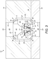
Figure 3 is a cross-sectional top view of the valve assembly ofFigure 1 ; -
Figure 4 is an orthographic view of a ball of the valve assembly ofFigure 1 ; -
Figure 5 is a table illustrating different states of operation of the valve assembly ofFigure 1 ; -
Figure 6 is a side view of a machine comprising the valve assembly of the present disclosure; and -
Figure 7 is a schematic of a fluid system of the machine ofFigure 6 comprising the valve assembly of the present disclosure. - The present disclosure is generally directed towards a ball for a valve assembly having a bore valve located in a first bore and a further second bore and a valve assembly comprising such a bore. The ball is rotatably mounted in a valve assembly such that it can be rotated between different states in which fluid can be prevented from passing through the ball, pass in both directions through the second bore and/or be controlled by the bore valve when passing through the first bore. The present disclosure further provides a fluid system comprising such a valve assembly, a machine comprising the valve assembly and fluid system and a method of operating the valve assembly.
-
Figures 1 to 3 illustrate avalve assembly 10, which may be aball valve assembly 10, in accordance with the presence disclosure. Thevalve assembly 10 comprises aball 11 in fluid communication with afirst valve port 12 and asecond valve port 13. Thevalve assembly 10 may be a singleline valve assembly 10 and therefore may not comprise any additional ports to the first andsecond valve ports valve assembly 10 comprises avalve housing 14, which may comprise first and secondvalve housing parts fixture 17, such as a plurality of bolts as illustrated. - The
ball 11 and first andsecond valve ports valve housing 14. Theball 11 may be rotatably mounted in thevalve housing 14 and may be operable to change its angular position about an axis ofrotation 18 in thevalve housing 14. Theball 11 may be constrained to rotate around only the axis ofrotation 18. Theball 11 may be actuatable between at least one closedstate open state rotation 18. - The
valve housing 14 may comprise aball chamber 20 in which theball 11 may be mounted. Aseal volume 27 may be formed in the space between theball 11 and theball chamber 20. - The
first valve port 12 may comprise afirst port passageway 21 extending through thevalve housing 14 from theball chamber 20 to the outside of thevalve housing 14 via a firstouter port aperture 23. Thesecond valve port 13 may comprise asecond port passageway 22 extending through thevalve housing 14 from theball chamber 20 to the outside of thevalve housing 14 via a secondouter port aperture 24. - The first and
second valve ports second port passageways outer port apertures ball 11. The centrelines of the first andsecond port passageways ball chamber 20 may have a greater diameter than the first and/orsecond port passageways Figure 2 . - The
valve assembly 10 may comprise avalve actuation arrangement 30 for controlling the angular position of theball 11 about the axis ofrotation 18, such as between the closed andopen states valve actuation arrangement 30 may comprise avalve actuator 31 and avalve stem 32 engaged with and/or mounted to theball 11. Thevalve actuator 31 may selectively control the angular position of thevalve stem 32 to control the angular position of theball 11. - The
valve stem 32 may extend through thevalve housing 14 and may be mounted to theball 11 such that thevalve stem 32 andball 11 are constrained to rotate together about the axis ofrotation 18. Thevalve stem 32 may be mounted in avalve stem passageway 33 through thevalve housing 14. Thevalve stem 32 andvalve stem passageway 33 may extend substantially orthogonally to the first andsecond port passageways 21, 22 (i.e. their centrelines extend in orthogonal directions to one another). Thevalve stem 32 may be sealed within thevalve stem passageway 33 by at least onevalve stem seal 34, which may be an O-ring as illustrated inFigure 2 . - As in the illustrated embodiment, the
valve actuator 31 may comprise a handle for an operator to manually control thevalve assembly 10, particularly by rotating the handle such that thevalve stem 32 rotates to change angular position of theball 11. However, thevalve actuator 31 may instead be controlled by a control system and may be electromechanical. For example, thevalve actuator 31 may comprise a solenoid, motor or the like. Furthermore, thevalve actuator 31 may directly control theball 11 by being mounted thereto and thevalve actuation arrangement 30 may not comprise thevalve stem 32. - As illustrated in further detail in
Figures 2 to 4 , theball 11 comprises afirst bore 40 for communicating fluid through theball 11 and asecond bore 41 for communicating fluid through theball 11. The first andsecond valve ports second bore ball 11 about the axis ofrotation 18. - The
ball 11 may comprise aball body 42 comprising a ballouter surface 43. The first andsecond bores ball body 42. Thus the first bore may extend between first bore first andsecond openings outer surface 43. The second bore may extend between second bore first andsecond openings outer surface 43. The first and second bore first andsecond openings second valve ports ball 11 about the axis ofrotation 18. - The
ball 11, particularly the ballouter surface 43 thereof, may comprise first, second, third and fourth blockingsurface regions second openings surface regions second valve ports ball 11 about the axis ofrotation 18. - The first
blocking surface region 35 may extend between the first bore first opening 44 and the second bore first opening 46. The secondblocking surface region 36 may extend between the second bore first opening 46 and the first boresecond opening 45. The thirdblocking surface region 37 may extend between the first bore second opening 45 and the second bore second opening 47. The fourthblocking surface region 38 may extend between the second bore second opening 47 and the first bore first opening 44. - The
second bore 41 may extend through thefirst bore 40 such that the first andsecond bores second bores first bore 40 may be in the range of about 75% to about 125% of the diameter of the second bore 41) and may have substantially the same diameter. - The first and
second bores rotation 18. The first andsecond bores second bores second bores ball body 42 such that their centrelines intersect the axis ofrotation 18. - The
ball 11 may comprise astem mount 50 for engaging and/or mounting with thevalve actuation arrangement 30, such as thevalve stem 32. The stem mount 50 may comprise a recess in the ballouter surface 43 as illustrated. The valve stem 32 may engage in the recess such that as thevalve stem 32 andball 11 are constrained to rotate together around the axis ofrotation 18. - The
ball body 42 and ballouter surface 43 may be shaped such that theball 11 is rotatable within thevalve housing 14 and therefore may be substantially spherically shaped. In particular, the ballouter surface 43 may extend substantially spherically. Theball body 42 may not have a completely spherical shape due to the first and second bore first andsecond openings outer surface 43 and forming indentations in the sphere. - The
valve assembly 10 may comprise aseal arrangement 60 comprising afluid vent 61, theseal volume 27 and at least oneball seal seal arrangement 60 may prevent fluid passing between the first andsecond valve ports ball 11 is in at least oneclosed state seal arrangement 60 may further comprise a seal, such as an O-ring seal, between the first and secondvalve housing parts - The at least one
ball seal ball chamber 20 and/orseal volume 27 from the first andsecond valve ports valve assembly 10 may comprise first and second ball seals 25, 26, which may be located in theball chamber 20 between theball 11 andvalve housing 14 and may be adjacent to the first and second port passageways 21, 22 respectively. The at least oneball seal seal volume 27 to the first orsecond valve ports ball 11 and theball chamber 20. The at least oneball seal - The
ball 11 may comprise thefluid vent 61 extending from the first and/orsecond bore ball 11, particularly of theball body 42. Thefluid vent 61 may be for fluid communication between the first and/orsecond bore seal volume 27. Thefluid vent 61 may As illustrated, thefluid vent 61 may comprise a passageway extending through theball body 42 from the first and/orsecond bore stem mount 50, such as the bottom of the recess. Thefluid vent 61 may have a smaller diameter of than the first and/orsecond bore second bore - The
seal arrangement 60 may provide a seal when theball 11 is in the at least oneclosed state open state 3, 7 (discussed further below) and there is a differential pressure acting in the closed direction. In particular, when theball 11 is in at least oneclosed state ball 11 onto the first orsecond ball seal second valve port fluid vent 61 may maintain the equal pressure in theseal volume 27 by enabling fluid flow therethrough. - The
ball 11 comprises abore valve 70 located in thefirst bore 40 for selectively allowing fluid to be communicated through thefirst bore 40. Although the present disclosure refers to thebore valve 70 being located in thefirst bore 40, it will be appreciated that the nomenclature of "first and second" bores 40, 41 may be interchanged such that thebore valve 70 may be considered to be located in the "second" bore 41. Furthermore, further bore valve(s) 70 may be located in the first and/orsecond bores - The
bore valve 70 may be a one-way valve and/or may be a check valve. Thebore valve 70 may be biased to a closed configuration as shown inFigure 2 . Thebore valve 70 may be selectively openable based upon a pressure differential across thebore valve 70 reaching a bore valve opening threshold. The type and arrangement of thebore valve 70 may be selected to have a suitable bore valve opening threshold for the fluid system in which thevalve assembly 10 may be located. Thebore valve 70 may be a poppet valve as illustrated, but may also be a reed valve, ball valve, butterfly valve or the like. - The
bore valve 70 may be located substantially entirely in theball body 42 and may not extend out of thefirst bore 40. Thebore valve 70 may not extend, or may extend only partially as illustrated, across thesecond bore 41, particularly when thebore valve 70 is open. Thebore valve 70 may be offset from the axis ofrotation 18 and/or offset along thefirst bore 40. In particular, thebore valve 70 may comprise a selectively openablebore valve opening 71 and thebore valve opening 71 may be offset from the axis ofrotation 18 and/or offset along thefirst bore 40. - The
bore valve 70 may comprise abore valve housing 72 mounted in thefirst bore 40. Thebore valve housing 72 may comprise at least onebore valve passageway 73 therethrough for fluid communication therethrough. Thefirst bore 40 may comprise afirst bore step 74, which may result from a step change in diameter along thefirst bore 40, and thebore valve housing 72 may be mounted and abut against thefirst bore step 74. - The
bore valve 70 may comprise at least oneretainer ring 75 and thebore valve housing 72 may be mounted between the at least oneretainer ring 75 andfirst bore step 74 such that thebore valve housing 72 is constrained axially along thefirst bore 40. Thefirst bore step 74 may be further from the axis ofrotation 18 than the at least oneretainer ring 75 as illustrated. Alternatively, thefirst bore step 74 may be closer to the axis ofrotation 18 than the at least one retainer ring 75 (i.e. their locations inFigure 2 are swapped). - Further alternatively, the
bore valve housing 72 may be fully integrated with and form part of theball body 42 such that thefirst bore step 74 and at least oneretainer ring 75 are not required. Alternatively thebore valve 70 and/or borevalve housing 72 may be press fitted, brazed, welded, friction welded, soldered, threaded or otherwise mounted into thefirst bore 40 and the at least oneretainer ring 75 may therefore not be required. - The
bore valve 70 may comprise, as illustrated inFigures 2 and3 , abore valve seat 76 to which abore valve head 77 may be selectively mounted. Thebore valve head 77 may be selectively moveable away from thebore valve seat 76 to form the bore valve opening 71 as inFigure 3 . Thebore valve head 77 may be attached to abore valve stem 78 mounted to a bore valve stem mount 79 in thebore valve housing 72. - As illustrated, the
bore valve 70 may comprise at least onespring 68 mounted to thebore valve stem 78 for biasing thebore valve head 77 towards the closed configuration in which nobore valve opening 71 is formed as inFigure 2 . - The
bore valve 70 may be configured such that it does not substantially impede or prevent flow through thesecond bore 41. In particular, thebore valve 70 may be configured such that thebore valve head 77 does not extend at all or only partially extends across thesecond bore 41 when in the open configuration as shown inFigure 3 . Thus thebore valve head 77 does not extend all the way across thesecond bore 41 and does not substantially interrupt the flow of fluid through thesecond bore 41. - In operation the
ball 11 is rotated by thevalve actuation arrangement 30 around the axis ofrotation 18 such that the first orsecond bore second valve ports valve assembly 10 may be operable in or configurable into a plurality ofdifferent states ball 11. -
Exemplary states Figure 5 . The first column illustrates the state number, namely states 1 to 8. The second column illustrates, for eachstate first valve port 12, illustrated as "A", to thesecond valve port 13, illustrated as "B", is on or off. The third column illustrates, for eachstate second valve port 13 to thefirst valve port 12 is on or off. The fourth column illustrates, for eachstate state 1. The fifth column graphically illustrates the angular position of theball 11 for eachstate first bore 40 is illustrated as comprising a check valve. - The
valve assembly 10 may be operable in at least oneopen state second bore second valve port valve assembly 10. - In at least one bidirectional
open state open states second bore 41 may be aligned with the first andsecond valve port ball 11 in both directions. However, the angular position of theball 11 and second bore 41 between the first and second bidirectionalopen states second openings second valve ports open state 1 and vice-versa in the second bidirectionalopen state 5. - In at least one controlled
open state open states first bore 40 may be aligned with the first andsecond valve port first bore 40 may be controlled by thebore valve 70. The angular position of theball 11 and first bore 40 between the first and second controlledopen states second openings second valve ports open state 3 and vice-versa in the second controlledopen state 7. - If the
bore valve 70 comprises a one-way valve as illustrated inFigure 5 , when thefirst bore 40 is aligned with the first andsecond valve port ball 11 in only one direction. Thus the first and second controlledopen states open states first bore 40 by adjusting the angular position of theball 11 by 180 degrees such that the one-way valve is configured to allow flow in the reverse direction. In the first and second unidirectionalopen states bore valve 70 opens in response to the bore valve opening threshold pressure being reached. - The
valve assembly 10 may be operable in at least oneclosed state second bore second valve port 12, 13 (instead they may be aligned with the ball chamber 20) such that fluid is blocked from flowing through theball 11 and through thevalve assembly 10. Theball 11 may comprise blockingsurface regions ball 11 when aligned with the first andsecond valve port surface regions second valve port ball 11 and through thevalve assembly 10. In particular, thevalve assembly 10 may be operable in fourclosed states surface regions second valve port - In order for the
valve assembly 10 to be operable in the plurality ofstates surface regions second valve ports valve assembly 10 may be configured such that the blockingsurface regions second valve ports second valve ports surface regions valve assembly 10 configured to control fluid flow through the fluid system. The fluid system may comprise at least one inlet conduit in fluid communication with thefirst valve port 12 and at least one outlet conduit in fluid communication with thesecond valve port 13. - The
valve assembly 10 illustrated inFigures 1 to 4 may be particularly applicable fluid systems for marine vessels and industrial systems, such as oil and gas refineries. However, the features and methods of operation disclosed herein may also be suitable for fluid systems in a machine, such as an excavator, truck (e.g. a dump truck), backhoe loader, another type of loader such as a wheel loader or track loader, dozer, shovel, material handler or telehandler. -
Figure 6 illustrates amachine 80 comprising afluid system 81 comprising thevalve assembly 10 of the present disclosure and configured to selectively control fluid flow through the fluid system. Themachine 80 may comprise amain body 82 and awork tool 83 attached to themain body 82. Thework tool 83 may be controlled by at least oneactuator 84. Thework tool 83 may comprise anarm arrangement 85 mounted to themain body 82 and an implement 86 attached to thearm arrangement 85 as illustrated. Thearm arrangement 85, may be controlled by the at least oneactuator 84 to move the implement 86 and perform work. In the illustrated embodiment themachine 80 comprises an excavator. - The
machine 80 may comprise agas spring arrangement 90 and, as further illustrated inFigure 7 , thefluid system 81 may comprise thegas spring arrangement 90. Thegas spring arrangement 90 may comprise first andsecond gas chambers piston 93 retractably and moveably mounted inside acylinder 94. Thegas spring arrangement 90 may be configured to store and release energy to assist in the operation of thework tool 83 in addition to the at least oneactuator 84 controlling thework tool 83. Alternatively, thegas spring arrangement 90 may be integrated with the at least oneactuator 84. Themachine 80 may comprise a plurality ofgas spring arrangements 90. - The
fluid system 81 may comprise at least oneconduit 95, at least onevalve assembly 10 and at least onefluid reservoir 96. The first andsecond gas chambers conduit 95 and fluid communication therebetween may be controlled by at least onevalve assembly 10. The at least onefluid reservoir 96 may be connected to the first andsecond gas chambers valve assembly 10. Thefluid system 81 may be apneumatic fluid system 81 such that the fluid is a gas. - The at least one
valve assembly 10 may be substantially similar to that disclosed inFigures 1 to 5 except that thevalve actuator 31 may not be a handle and may instead be controlled by a control system and/or by a servo actuator commanded by a control system (not illustrated). Thefluid system 81 may therefore be controlled to selectively store and release energy by controlling the flow of fluid between thefirst gas chamber 91,second gas chamber 92 and at least onefluid reservoir 96. - The
valve assembly 10 of the present disclosure enables a plurality of flow logic states 1, 2, 3, 4, 5, 6, 7, 8 (as illustrated inFigure 5 ) to be implemented in asingle valve assembly 10 rather than in a fluid system comprising separate on-off valves and one-way valves. In particular, thevalve assembly 10 enable fluid flow between the first andsecond valve ports - Furthermore, the
valve assembly 10 provides a plurality ofstates valve assembly 10 is operable in fourclosed states open states valve assembly 10 when switching betweenstates multiple states valve assembly 10 can be operated to theappropriate state - By virtue of the
bore valve 70 being offset from the axis ofrotation 18 it may not substantially block fluid flowing along thesecond bore 41 when thevalve assembly 10 is in the first or second bidirectionalopen state bore valve head 77 only extends partially across thesecond bore 41 when opened, is particularly suitable in achieving such an effect.
Claims (15)
- A ball for a valve assembly comprising:a first bore for communicating fluid through the ball;a second bore for communicating fluid through the ball; anda bore valve located in the first bore for selectively enabling fluid communication through the first bore.
- A ball as claimed in claim 1 wherein the second bore extends through the first bore such that the first and second bores are in fluid communication with one another.
- A ball as claimed in claim 1 or claim 2 wherein the first and second bores extend orthogonally to one another.
- A ball as claimed in any one of the preceding claims wherein the bore valve is a one-way valve.
- A ball as claimed in any one of the preceding claims wherein the valve comprises a selectively openable valve opening and the valve opening is offset from the centre of the ball.
- A ball as claimed in any one of the preceding claims wherein the ball comprises a ball outer surface, the first bore extends between first bore first and second openings at the ball outer surface, the second bore extends between second bore first and second openings at the ball outer surface and the ball further comprises first, second, third and fourth blocking surface regions between the adjacent first and second bore first and second openings.
- A ball as claimed in any one of the preceding claims wherein the ball comprises a stem mount for engaging and/or mounting with a valve actuation arrangement of the valve assembly.
- A ball as claimed in any one of the preceding claims wherein the ball comprises a fluid vent extending from the first and/or second bore to outside of the ball.
- A ball as claimed in any one of the preceding claims wherein the bore valve comprises a bore valve housing mounted in the first bore, the first bore comprises a first bore step and the bore valve housing is mounted and abuts against the first bore step.
- A valve assembly comprising:a valve housing;a ball according to any one of the preceding claims, wherein the ball is mounted in the valve housing for rotation about an axis of rotation; andfirst and second valve ports in fluid communication with the first or second bore based upon an angular position of the ball about the axis of rotation.
- A valve assembly as claimed in claim 10 wherein the valve assembly is configurable into at least one of:at least one bidirectional open state in which the second bore is aligned with the first and second valve port such that fluid is able to flow through the ball in both directions;at least one controlled open state in which the first bore is aligned with the first and second valve port and fluid flow through the first bore is controlled by the bore valve; and/orat least one closed state in which the first or second bore are not aligned with the first and second valve port such that fluid is blocked from flowing through the ball.
- A valve assembly as claimed in claim 10 or claim 11 further comprising a seal arrangement for preventing fluid from passing from the first to second valve ports and/or vice versa.
- A machine comprising a fluid system comprising a valve assembly of any one of claims 10 to 12 configured to selectively control fluid flow through the fluid system.
- A method of operating the valve assembly of any one of claims 10 to 12 comprising rotating the ball around the axis of rotation such that the first or second bore is aligned with or not aligned with the first and second valve ports.
- A method as claimed in claim 14 comprising rotating the ball into at least one of:at least one bidirectional open state in which the second bore is aligned with the first and second valve port such that fluid is able to flow through the ball in both directions;at least one controlled open state in which the first bore is aligned with the first and second valve port and fluid flow through the first bore is controlled by the bore valve; and/orat least one closed state in which the first or second bore are not aligned with the first and second valve port such that fluid is blocked from flowing through the ball.
Priority Applications (6)
| Application Number | Priority Date | Filing Date | Title |
|---|---|---|---|
| EP20156216.2A EP3862602A1 (en) | 2020-02-07 | 2020-02-07 | Ball for a valve assembly |
| CN202180011733.3A CN115023564A (en) | 2020-02-07 | 2021-02-01 | ball for valve assembly |
| US17/797,805 US20230057318A1 (en) | 2020-02-07 | 2021-02-01 | Ball for a Valve Assembly |
| BR112022014987A BR112022014987A2 (en) | 2020-02-07 | 2021-02-01 | BALL FOR A VALVE ASSEMBLY |
| PCT/US2021/016021 WO2021158467A1 (en) | 2020-02-07 | 2021-02-01 | Ball for a valve assembly |
| AU2021216366A AU2021216366B2 (en) | 2020-02-07 | 2021-02-01 | Ball for a valve assembly |
Applications Claiming Priority (1)
| Application Number | Priority Date | Filing Date | Title |
|---|---|---|---|
| EP20156216.2A EP3862602A1 (en) | 2020-02-07 | 2020-02-07 | Ball for a valve assembly |
Publications (1)
| Publication Number | Publication Date |
|---|---|
| EP3862602A1 true EP3862602A1 (en) | 2021-08-11 |
Family
ID=69528633
Family Applications (1)
| Application Number | Title | Priority Date | Filing Date |
|---|---|---|---|
| EP20156216.2A Pending EP3862602A1 (en) | 2020-02-07 | 2020-02-07 | Ball for a valve assembly |
Country Status (6)
| Country | Link |
|---|---|
| US (1) | US20230057318A1 (en) |
| EP (1) | EP3862602A1 (en) |
| CN (1) | CN115023564A (en) |
| AU (1) | AU2021216366B2 (en) |
| BR (1) | BR112022014987A2 (en) |
| WO (1) | WO2021158467A1 (en) |
Citations (6)
| Publication number | Priority date | Publication date | Assignee | Title |
|---|---|---|---|---|
| DE2833924A1 (en) * | 1978-08-02 | 1980-02-21 | Roetelmann & Co | HYDRAULIC SWITCHING GROUP |
| GB2203819A (en) * | 1987-04-10 | 1988-10-26 | Richard Alder | Valve |
| DE19754566A1 (en) * | 1997-12-09 | 1999-06-10 | Wildfang Dieter Gmbh | Backflow prevention valve for water supply |
| US20040206404A1 (en) | 2003-04-21 | 2004-10-21 | Chih-Hung Yang | Rotatable ball valve assembly |
| EP2447624A2 (en) * | 2010-10-28 | 2012-05-02 | Vaillant GmbH | Heat pump |
| US20160138723A1 (en) * | 2014-11-18 | 2016-05-19 | Saudi Arabian Oil Company | Isolatable Non-Slam Piston Check Valve |
Family Cites Families (47)
| Publication number | Priority date | Publication date | Assignee | Title |
|---|---|---|---|---|
| US1185333A (en) * | 1915-04-14 | 1916-05-30 | Delmar Daniel Keltner | Reversible valve. |
| US2399300A (en) * | 1941-08-29 | 1946-04-30 | Crown Cork & Seal Co | Filling apparatus and valve |
| US3363650A (en) * | 1963-10-14 | 1968-01-16 | Scaramucci Domer | Combination plug and check valve |
| US3146792A (en) * | 1963-12-11 | 1964-09-01 | William H Donnelly | Ball valve |
| US3348569A (en) * | 1964-11-30 | 1967-10-24 | Halliburton Co | Valves |
| US3491796A (en) * | 1966-06-03 | 1970-01-27 | Domer Scaramucci | Combined stop and check valve |
| US3503415A (en) * | 1966-06-08 | 1970-03-31 | Fischer & Porter Co | Ball valve and construction thereof |
| US3565099A (en) * | 1970-01-02 | 1971-02-23 | John M Young | Reversible check valve |
| US3854497A (en) * | 1971-07-01 | 1974-12-17 | Lampert S | Combination shut-off valve and flow control valve with side access and viewing port for observation, testing and on-line servicing |
| CA1057269A (en) * | 1975-09-17 | 1979-06-26 | E. Frederick Schoeneweis | Sealing member for valve stems |
| US4254836A (en) * | 1978-04-10 | 1981-03-10 | Russell Larry R | Methods and apparatus for controlling fluid flow |
| US4220176A (en) * | 1978-04-10 | 1980-09-02 | Russell Larry R | Methods and apparatus for controlling fluid flow |
| US4226263A (en) * | 1978-08-14 | 1980-10-07 | Valve Concepts International | Erosion control trim in a control mechanism for a ball valve |
| JPS56134672A (en) * | 1980-03-25 | 1981-10-21 | Fuji Kinzoku Kosaku Kk | Ball valve |
| US4655078A (en) * | 1985-01-30 | 1987-04-07 | Johnson Augustus W | Sprinkler drain and test valve |
| GB8514420D0 (en) * | 1985-06-07 | 1985-07-10 | Forsac Valves Inc | Valve assembly |
| US5588462A (en) * | 1986-06-16 | 1996-12-31 | Agf Manufacturing, Inc. | Valve and sensor arrangement |
| US5269344A (en) * | 1986-06-16 | 1993-12-14 | Agf Manufacturing, Inc. | Supply valve and arrangement for fire suppression water sprinkler system |
| US4852610A (en) * | 1986-06-16 | 1989-08-01 | Agf Manufacturing, Inc. | Valve and arrangement for fire suppression water sprinkler system |
| US5406979A (en) * | 1986-06-16 | 1995-04-18 | Acf Manufacturing, Inc. | Valve and sensor arrangement |
| JPH0520933Y2 (en) * | 1987-05-21 | 1993-05-28 | ||
| JPH02141772U (en) * | 1989-04-28 | 1990-11-29 | ||
| US4936547A (en) * | 1989-12-11 | 1990-06-26 | Worcester Controls Corporation | Eccentric ball valve |
| US5010916A (en) * | 1990-03-23 | 1991-04-30 | Albrecht David E | Check valve |
| IT1254821B (en) * | 1992-02-28 | 1995-10-11 | Mario Giacomini | BALL VALVE |
| US5373868A (en) * | 1993-12-03 | 1994-12-20 | Bertito T. Rodriguez | Ball valve with modular check valve assembly and access port |
| US5437307A (en) * | 1994-06-27 | 1995-08-01 | Cianfrocca, Ii; Lawrence D. | Intake bypass valve |
| US5586579A (en) * | 1995-11-15 | 1996-12-24 | Martin Marietta Corporation | Combination ball valve and pressure relief valve assembly |
| US5944051A (en) * | 1997-09-25 | 1999-08-31 | Johnson; Augustus W. | Sprinkler drain and test valve |
| US6186169B1 (en) * | 1999-08-19 | 2001-02-13 | Agf Manufacturing, Inc. | Valve and arrangement for fire suppression system |
| US6098659A (en) * | 2000-01-04 | 2000-08-08 | J. Barry Cook | Combined directional and flow control valve |
| US6814101B2 (en) * | 2002-07-31 | 2004-11-09 | Umac Inc. | Excessive flow valve |
| US7178544B2 (en) * | 2003-07-31 | 2007-02-20 | Perfection Corporation | Combination shut-off and resetable excess flow valve |
| US7174915B2 (en) * | 2003-11-24 | 2007-02-13 | Dale Fazekas | Water re-circulation valve |
| US7051763B2 (en) * | 2004-04-30 | 2006-05-30 | L.R. Nelson Corporation | Faucet adapter |
| US20080135794A1 (en) * | 2006-12-06 | 2008-06-12 | Haim Shnider | Rotary valve |
| US20150129043A1 (en) * | 2013-11-08 | 2015-05-14 | Richard C. Hughes | Valves with multi-directional ball check |
| US8910655B2 (en) * | 2013-04-05 | 2014-12-16 | Kofulso Co., Ltd. | Gas valve having automatically blocking means |
| US10550945B2 (en) * | 2013-04-25 | 2020-02-04 | Ohio University | Emergency shutdown valves with bypass features |
| US9377116B2 (en) * | 2013-09-16 | 2016-06-28 | The Boeing Company | Valve and method of relieving overpressure in a fluid supply system |
| US9377113B2 (en) * | 2013-11-18 | 2016-06-28 | Mikron Valve & Manufacturer, Inc. | Spherical automatic flow emergency restrictor valve |
| CN203948711U (en) * | 2014-05-06 | 2014-11-19 | 凯迈(洛阳)气源有限公司 | A kind of multi-path ball valve |
| CN205479455U (en) * | 2016-04-06 | 2016-08-17 | 丹佛斯(天津)有限公司 | But bidirectional operation's ball valve |
| US10641398B2 (en) * | 2016-05-13 | 2020-05-05 | Red-White Valve Corp. | Ball valve with integrated fitting |
| US10502333B2 (en) * | 2016-11-28 | 2019-12-10 | Red-White Valve Corp. | Ball valve with components integrated into the ball member |
| IT201700028274A1 (en) * | 2017-03-14 | 2018-09-14 | Effebi Spa | SPHERE FOR A HYDRAULIC COMPONENT, INSERT VARIATOR FLOW INCLUDING THE SPHERE AND TAP INCLUDING THE SPHERE |
| US20190078695A1 (en) * | 2017-09-08 | 2019-03-14 | Effebi S.P.A. | Valve assembly |
-
2020
- 2020-02-07 EP EP20156216.2A patent/EP3862602A1/en active Pending
-
2021
- 2021-02-01 CN CN202180011733.3A patent/CN115023564A/en active Pending
- 2021-02-01 US US17/797,805 patent/US20230057318A1/en active Pending
- 2021-02-01 AU AU2021216366A patent/AU2021216366B2/en active Active
- 2021-02-01 WO PCT/US2021/016021 patent/WO2021158467A1/en not_active Ceased
- 2021-02-01 BR BR112022014987A patent/BR112022014987A2/en unknown
Patent Citations (6)
| Publication number | Priority date | Publication date | Assignee | Title |
|---|---|---|---|---|
| DE2833924A1 (en) * | 1978-08-02 | 1980-02-21 | Roetelmann & Co | HYDRAULIC SWITCHING GROUP |
| GB2203819A (en) * | 1987-04-10 | 1988-10-26 | Richard Alder | Valve |
| DE19754566A1 (en) * | 1997-12-09 | 1999-06-10 | Wildfang Dieter Gmbh | Backflow prevention valve for water supply |
| US20040206404A1 (en) | 2003-04-21 | 2004-10-21 | Chih-Hung Yang | Rotatable ball valve assembly |
| EP2447624A2 (en) * | 2010-10-28 | 2012-05-02 | Vaillant GmbH | Heat pump |
| US20160138723A1 (en) * | 2014-11-18 | 2016-05-19 | Saudi Arabian Oil Company | Isolatable Non-Slam Piston Check Valve |
Also Published As
| Publication number | Publication date |
|---|---|
| AU2021216366B2 (en) | 2026-03-12 |
| US20230057318A1 (en) | 2023-02-23 |
| CN115023564A (en) | 2022-09-06 |
| AU2021216366A1 (en) | 2022-09-01 |
| BR112022014987A2 (en) | 2022-09-20 |
| WO2021158467A1 (en) | 2021-08-12 |
Similar Documents
| Publication | Publication Date | Title |
|---|---|---|
| US9027597B2 (en) | Operating device | |
| CN110939622B (en) | Hydraulic pressure compensation plate with integrated load sensing | |
| US20150059900A1 (en) | Rotary valve | |
| CA2560318A1 (en) | Valve, actuator and control system therefor | |
| US6173639B1 (en) | Fluid control system having float control | |
| KR20170037835A (en) | Direction converter valve and hydraulic system | |
| WO2013009601A1 (en) | Proportional poppet valve with integral check valves | |
| AU2021216366B2 (en) | Ball for a valve assembly | |
| WO2021059614A1 (en) | Flow control valve | |
| CN100591872C (en) | Hydraulic systems of work vehicles | |
| US3744522A (en) | Multiple outlet spool valve | |
| CN114576224B (en) | A control valve, a reversing valve and a control system thereof | |
| US3386471A (en) | Flow control and cushioning valve | |
| US4489644A (en) | Multiple control valves | |
| EP2833002B1 (en) | Control valve device for power shovel | |
| JP6918538B2 (en) | Multiple direction switching valve | |
| KR101779194B1 (en) | Device for Controlling the oil of Construction Machinery | |
| JP7397561B2 (en) | valve device | |
| JP2871112B2 (en) | Swivel circuit of construction machinery | |
| CN214838521U (en) | Valve device and valve block | |
| AU2020335999B2 (en) | Fluid distribution assembly | |
| JP2000346007A (en) | Two-speed hydraulic motor control circuit and sequence valve | |
| JP2019060373A (en) | Hydraulic motor control device | |
| KR101619118B1 (en) | Sysyem for opening and closing valve of vessel | |
| US20230134654A1 (en) | Flow path switching valve, and construction machine equipped with same |
Legal Events
| Date | Code | Title | Description |
|---|---|---|---|
| PUAI | Public reference made under article 153(3) epc to a published international application that has entered the european phase |
Free format text: ORIGINAL CODE: 0009012 |
|
| STAA | Information on the status of an ep patent application or granted ep patent |
Free format text: STATUS: THE APPLICATION HAS BEEN PUBLISHED |
|
| AK | Designated contracting states |
Kind code of ref document: A1 Designated state(s): AL AT BE BG CH CY CZ DE DK EE ES FI FR GB GR HR HU IE IS IT LI LT LU LV MC MK MT NL NO PL PT RO RS SE SI SK SM TR |
|
| STAA | Information on the status of an ep patent application or granted ep patent |
Free format text: STATUS: REQUEST FOR EXAMINATION WAS MADE |
|
| 17P | Request for examination filed |
Effective date: 20220107 |
|
| RBV | Designated contracting states (corrected) |
Designated state(s): AL AT BE BG CH CY CZ DE DK EE ES FI FR GB GR HR HU IE IS IT LI LT LU LV MC MK MT NL NO PL PT RO RS SE SI SK SM TR |
|
| STAA | Information on the status of an ep patent application or granted ep patent |
Free format text: STATUS: EXAMINATION IS IN PROGRESS |
|
| 17Q | First examination report despatched |
Effective date: 20231010 |