EP3862564B1 - Light and shadow flicker control method for wind turbine generator system - Google Patents
Light and shadow flicker control method for wind turbine generator system Download PDFInfo
- Publication number
- EP3862564B1 EP3862564B1 EP20848778.5A EP20848778A EP3862564B1 EP 3862564 B1 EP3862564 B1 EP 3862564B1 EP 20848778 A EP20848778 A EP 20848778A EP 3862564 B1 EP3862564 B1 EP 3862564B1
- Authority
- EP
- European Patent Office
- Prior art keywords
- angle
- yaw
- area
- proceeding
- wind turbine
- Prior art date
- Legal status (The legal status is an assumption and is not a legal conclusion. Google has not performed a legal analysis and makes no representation as to the accuracy of the status listed.)
- Active
Links
Images


Classifications
-
- F—MECHANICAL ENGINEERING; LIGHTING; HEATING; WEAPONS; BLASTING
- F03—MACHINES OR ENGINES FOR LIQUIDS; WIND, SPRING, OR WEIGHT MOTORS; PRODUCING MECHANICAL POWER OR A REACTIVE PROPULSIVE THRUST, NOT OTHERWISE PROVIDED FOR
- F03D—WIND MOTORS
- F03D80/00—Details, components or accessories not provided for in groups F03D1/00 - F03D17/00
- F03D80/20—Arrangements for avoiding shadow flicker
-
- F—MECHANICAL ENGINEERING; LIGHTING; HEATING; WEAPONS; BLASTING
- F03—MACHINES OR ENGINES FOR LIQUIDS; WIND, SPRING, OR WEIGHT MOTORS; PRODUCING MECHANICAL POWER OR A REACTIVE PROPULSIVE THRUST, NOT OTHERWISE PROVIDED FOR
- F03D—WIND MOTORS
- F03D7/00—Controlling wind motors
-
- F—MECHANICAL ENGINEERING; LIGHTING; HEATING; WEAPONS; BLASTING
- F03—MACHINES OR ENGINES FOR LIQUIDS; WIND, SPRING, OR WEIGHT MOTORS; PRODUCING MECHANICAL POWER OR A REACTIVE PROPULSIVE THRUST, NOT OTHERWISE PROVIDED FOR
- F03D—WIND MOTORS
- F03D7/00—Controlling wind motors
- F03D7/02—Controlling wind motors the wind motors having rotation axis substantially parallel to the air flow entering the rotor
- F03D7/0204—Controlling wind motors the wind motors having rotation axis substantially parallel to the air flow entering the rotor for orientation in relation to wind direction
-
- F—MECHANICAL ENGINEERING; LIGHTING; HEATING; WEAPONS; BLASTING
- F05—INDEXING SCHEMES RELATING TO ENGINES OR PUMPS IN VARIOUS SUBCLASSES OF CLASSES F01-F04
- F05B—INDEXING SCHEME RELATING TO WIND, SPRING, WEIGHT, INERTIA OR LIKE MOTORS, TO MACHINES OR ENGINES FOR LIQUIDS COVERED BY SUBCLASSES F03B, F03D AND F03G
- F05B2270/00—Control
- F05B2270/10—Purpose of the control system
- F05B2270/19—Purpose of the control system to avoid stroboscopic flicker shadow on surroundings
-
- F—MECHANICAL ENGINEERING; LIGHTING; HEATING; WEAPONS; BLASTING
- F05—INDEXING SCHEMES RELATING TO ENGINES OR PUMPS IN VARIOUS SUBCLASSES OF CLASSES F01-F04
- F05B—INDEXING SCHEME RELATING TO WIND, SPRING, WEIGHT, INERTIA OR LIKE MOTORS, TO MACHINES OR ENGINES FOR LIQUIDS COVERED BY SUBCLASSES F03B, F03D AND F03G
- F05B2270/00—Control
- F05B2270/30—Control parameters, e.g. input parameters
- F05B2270/329—Azimuth or yaw angle
-
- Y—GENERAL TAGGING OF NEW TECHNOLOGICAL DEVELOPMENTS; GENERAL TAGGING OF CROSS-SECTIONAL TECHNOLOGIES SPANNING OVER SEVERAL SECTIONS OF THE IPC; TECHNICAL SUBJECTS COVERED BY FORMER USPC CROSS-REFERENCE ART COLLECTIONS [XRACs] AND DIGESTS
- Y02—TECHNOLOGIES OR APPLICATIONS FOR MITIGATION OR ADAPTATION AGAINST CLIMATE CHANGE
- Y02E—REDUCTION OF GREENHOUSE GAS [GHG] EMISSIONS, RELATED TO ENERGY GENERATION, TRANSMISSION OR DISTRIBUTION
- Y02E10/00—Energy generation through renewable energy sources
- Y02E10/70—Wind energy
- Y02E10/72—Wind turbines with rotation axis in wind direction
Definitions
- the present disclosure relates to a method for controlling shadow flickers of a wind turbine.
- a shadow flicker is a term referring to light and shadow flashing due to the wind turbine blade rotation under the sun.
- the light and shadow flashing in this way may have a serious impact on residents and farmed animals near the wind turbine. Since there may be adverse effects caused by shadow flickers on human beings, a method for accurately controlling shadow flickers is required to regulate and control the wind turbine in real time, so as to prevent the shadow flickers caused by the wind turbine from impacting sensitive areas. If the light condition is not met at a time t, the yaw-forbidden area is empty, and the sensitive area is not affected by light and shadow.
- the yaw-prohibited area ⁇ which will cause light and shadow influence at the time T. If a current yaw angle Angle_At is not within the yaw-prohibited area ⁇ , no light and shadow influence exists at the time T. If the previous current yaw angle Angle At is within the yaw-prohibited area ⁇ , it is determined whether the yaw-allowable area ⁇ is included in ⁇ . If ⁇ , the wind turbine should be shut down, and if ⁇ is not included in ⁇ , the yaw angle is adjusted to reach a proper value to keep the wind turbine running.
- US 20190271296A1 discloses a system and method for managing shadow flicker of a wind turbine. It is provided to determine whether the distance between the wind turbine and the receptor is within a shadow range of the receptor based on at the time of day or year and if so, determine whether shadows of the wind turbine are cast in the direction of the receptor based on the spatial location of the wind turbine. Further, the method provides comparing the yaw angle to a predetermined angle range in advance which is predetermined. Additionally, the method provides determining whether shadow flicker is occurring at the receptor based, at least in part, on the sun position, the spatial location of the wind turbine, and the light intensity.
- CN 103590975B discloses a system and method for controlling a wind turbine. It is provided to calculate the shadow area based on parameters such as local latitude, local time zone, tower height, blade length, local light information, date and time, the angle between the nacelle and the north direction and the solar altitude angle h, and compare the shadow area with the local residential area to determine whether the yaw motor will be controlled to perform certain avoidance actions such as adjustment of the yaw angle, however the flicker can be reduced by yawing the wind turbine by up to 15° , otherwise the wind turbine is shut down.
- JP 4585151B2 discloses a method for controlling a wind turbine. It is provided to calculate the shadow area based on information such as the sun altitude and azimuth, the rotor diameter and the height of the hub, and compare the shadow area with the specific area to determine whether the rotor will be controlled to perform certain avoidance actions such as stop the rotor.
- the present invention provides a method for controlling shadow flickers of a wind turbine according to claim 1.
- a safe and reliable method which is easy in algorithm, for controlling shadow flickers of a wind turbine.
- a method for controlling shadow flickers of a wind turbine including:
- Step 2 is specified as follows:
- Step 2.1 is specified as follows:
- Step 2.5 is specified as follows:
- Step 3 is specified as follows:
- the determination and selection measures to prevent the light and shadow influence in Step 4 are specified as follows: determining whether the current yaw angle is in the yaw-prohibited area or not, and keeping the wind turbine running if not, or otherwise, if yes, continuing to determine if the yaw-allowable area is included in the yaw-prohibited area and, if so, shutting down the wind turbine, or otherwise, if the yaw-allowable area is incompletely included in the yaw-prohibited area, adjusting the yaw angle to depart from the yaw-prohibited area and keeping the wind turbine running.
- the advantages of the present disclosure are: taking into consideration the influence of an actual spatial intersection of a rotor swept area projection area and a sensitive area, the present disclosure selects a reasonable control strategy by calculating the yaw-prohibited area causing the light and shadow influence at the time t, determining a current yaw angle, and a relationship between the yaw-allowable area and the yaw-prohibited area, so as to keep in line with the actual running of the wind turbine.
- a method for controlling shadow flickers of a wind turbine as show in Figs. 1-5 including:
Landscapes
- Engineering & Computer Science (AREA)
- Life Sciences & Earth Sciences (AREA)
- Sustainable Development (AREA)
- Sustainable Energy (AREA)
- Chemical & Material Sciences (AREA)
- Combustion & Propulsion (AREA)
- Mechanical Engineering (AREA)
- General Engineering & Computer Science (AREA)
- Wind Motors (AREA)
Description
- The present disclosure relates to a method for controlling shadow flickers of a wind turbine.
- A shadow flicker is a term referring to light and shadow flashing due to the wind turbine blade rotation under the sun. The light and shadow flashing in this way may have a serious impact on residents and farmed animals near the wind turbine. Since there may be adverse effects caused by shadow flickers on human beings, a method for accurately controlling shadow flickers is required to regulate and control the wind turbine in real time, so as to prevent the shadow flickers caused by the wind turbine from impacting sensitive areas. If the light condition is not met at a time t, the yaw-forbidden area is empty, and the sensitive area is not affected by light and shadow. If the light intensity condition is met, and the intersection of a rotor swept area projection area and the sensitive area is empty at the time t, projected area will not be affected by shadow flickers; and if the intersection is not empty, it means that the sensitive area is affected by shadow flickers at that moment.
- In order to control the shadow flickers of the wind turbine in real time, it is required to calculate the yaw-prohibited area Φ which will cause light and shadow influence at the time T. If a current yaw angle Angle_At is not within the yaw-prohibited area Φ, no light and shadow influence exists at the time T. If the previous current yaw angle Angle At is within the yaw-prohibited area Φ, it is determined whether the yaw-allowable area ξ is included in Φ. If ξ⊆Φ, the wind turbine should be shut down, and if ξ is not included in Φ, the yaw angle is adjusted to reach a proper value to keep the wind turbine running.
- Few researches have been carried out on methods for controlling shadow flickers at home and abroad, and existing patent technologies that have been published include: 1) a method for evaluating light and shadow in a wind farm and device and system for the same, which discloses a method for evaluating a light and shadow range in the wind farm by determining an influence range according to a minimum distance between a relative coordinate point of an object center and a real-time light and shadow influence range, as well as an object range, wherein the influence range is simplified as a circle centered at a projection C of a hub center onto the ground and with a radius r.
-
US 20190271296A1 discloses a system and method for managing shadow flicker of a wind turbine. It is provided to determine whether the distance between the wind turbine and the receptor is within a shadow range of the receptor based on at the time of day or year and if so, determine whether shadows of the wind turbine are cast in the direction of the receptor based on the spatial location of the wind turbine. Further, the method provides comparing the yaw angle to a predetermined angle range in advance which is predetermined. Additionally, the method provides determining whether shadow flicker is occurring at the receptor based, at least in part, on the sun position, the spatial location of the wind turbine, and the light intensity. -
CN 103590975B discloses a system and method for controlling a wind turbine. It is provided to calculate the shadow area based on parameters such as local latitude, local time zone, tower height, blade length, local light information, date and time, the angle between the nacelle and the north direction and the solar altitude angle h, and compare the shadow area with the local residential area to determine whether the yaw motor will be controlled to perform certain avoidance actions such as adjustment of the yaw angle, however the flicker can be reduced by yawing the wind turbine by up to 15° , otherwise the wind turbine is shut down. -
JP 4585151B2 - In order to solve the above-mentioned technical problems, the present invention provides a method for controlling shadow flickers of a wind turbine according to claim 1. In particular, it is provided a safe and reliable method, which is easy in algorithm, for controlling shadow flickers of a wind turbine.
- A method for controlling shadow flickers of a wind turbine is disclosed, including:
- in a Step 1, acquiring a current time of a wind farm;
- in a Step 2, calculating a yaw-prohibited area that is affected by shadow flickers at the current moment;
- in a Step 3, acquiring a current yaw angle of the wind turbine, and calculating a yaw-allowable area according to the yaw angle; and
- in a Step 4, determining and selecting measures to avoid the influence of shadow flickers according to the current yaw angle as well as the relationship between the yaw-prohibited area and the yaw-allowable area.
- According to the method mentioned above for controlling shadow flickers of the wind turbine, Step 2 is specified as follows:
- In a Step 2.1: building a
reference coordinate system 0, and proceeding to a Step 2.2; - in Step 2.2: obtaining a yaw rotation centric coordinate point P, a rotor swept area radius R, and a distance R0 from the rotor swept area center to the yaw rotation center, wherein the rotor swept area is a blade surface that a blade sweeps about a rotation center; and proceeding to a Step 2.3;
- in Step 2.3: determining whether a sun light exposure intensity i is larger or equal to a light intensity threshold I, and, if so, proceeding to a Step 2.4, or keeping the wind turbine running if not;
- in Step 2.4: calculating a sun altitude angle h0 and a sun azimuth angle A at the current time t, and proceeding to a Step 2.5; and
- in Step 2.5: calculating the yaw-prohibited area Φ meeting the light intensity condition.
- According to the method mentioned above for controlling shadow flickers of the wind turbine, Step 2.1 is specified as follows:
- in a Step 2.1.1: building an X-Y plane in a horizontal plane where the lowest point of the sensitive area Ψ is located, wherein the sensitive area Ψ to be determined is a potential area impacted by shadow flickers; and proceeding to a Step 2.1.2;
- in Step 2.1.2: building a Y-Z plane in a south-north vertical plane where a centric point of the sensitive area Ψ is located; and proceeding to a Step 2.1.3;
- in Step 2.1.3: building an X-Z plane in an east-west vertical plane where a centric point of the yaw rotation is located; and proceeding to a Step 2.1.4;
- in Step 2.1.4: taking an X axis as an intersecting line between the X-Y plane and the X-Z plane, and East as a positive direction; and proceeding to a Step 2.1.5;
- in Step 2.1.5: taking a Y axis as an intersecting line between the X-Y plane and the Y-Z plane, and North as a positive direction; and proceeding to a Step 2.1.6;
- in Step 2.1.6: taking a Z axis as an intersecting line between the X-Z plane and the Y-Z plane, and a top direction as a positive direction; and proceeding to Step 2.2.
- According to the method mentioned above for controlling shadow flickers of the wind turbine, Step 2.5 is specified as follows:
- in a Step 2.5.1: initializing Φ =ø, and initializing S=ø, wherein S is the intersection of the rotor swept area projection area and the sensitive area; and proceeding to a Step 2.5.2;
- in Step 2.5.2: checking through all angles Angle_At' within [0,2π], wherein Angle_At' is a yaw angle between the rotor swept area and the south direction and taking the clockwise direction as the positive direction; and proceeding to a Step 2.5.3;
- in Step 2.5.3: assuming the yaw angle as Angle_At', and calculating the space Ωt at the projection boundary of the rotor swept area impacting the sensitive area as:
- Ωt={(X,Y,Z)|X=Rcosθsin(Angle_At')+R0cos(Angle_At')+Dx+(Rsinθ+Dh-Z)sinA/tan(h 0), Y=Rcosθcos(Angle_At')-Rosin(Angle_At')+(Rsinθ+Dh-Z)cosA/tan(h0), Z=Z,θ∈[0,2π],Z∈[0,r_h]};
- wherein θ represents a calculation angle, Dx represents a coordinate of the yaw rotation center on the X axis, Dh represents a height of the yaw rotation center, r_h represents a height of the sensitive area Ψ;
- and then proceeding to a Step 2.5.4;
- in Step 2.5.4: assuming the yaw angle as Angle_At', and checking through all points within the sensitive area, wherein if the point
- (x,y,z)∈Ψ={(Xg,Yg,Zg)|Xg ∈[-0.5r_1•cos(Angle_rl), 0.5r_1•cos(Angle_rl)], Zg∈[0,r_h]; Yg=Dy-Xg•tan(Angle_rl)} is within the Ωt, S=S U (x,y,z);
- wherein Xg is an X axis coordinate component in the sensitive area; Yg is an Y axis coordinate component in the sensitive area; Zg is an Z axis coordinate component in the sensitive area; r_l is a length of the sensitive area Ψ; Angle rl is an angle between a direction where the sensitive area Ψ heads to and the east-west direction, and the clockwise direction is taken as the positive direction; Dy is the coordinate of the sensitive area center on the Y axis;
- and then proceeding to a Step 2.5.5;
- in Step 2.5.5: the yaw-prohibited area Φ={Angle_At'|when the yaw is at Angle_At', S ≠ø}; and proceeding to a Step 3.
- According to the method mentioned above for controlling shadow flickers of the wind turbine, Step 3 is specified as follows:
- in a Step 3.1: obtaining an allowable yaw amplitude Angle_a based on the wind turbine running status, and proceeding to a Step 3.2;
- in Step 3.2: the yaw-allowable area ξ={α|α∈[Angle_At-Angle_a,Angle_At+Angle_a]}, and proceeding to a Step 4.
- According to the method mentioned above for controlling shadow flickers of the wind turbine, the determination and selection measures to prevent the light and shadow influence in Step 4 are specified as follows:
determining whether the current yaw angle is in the yaw-prohibited area or not, and keeping the wind turbine running if not, or otherwise, if yes, continuing to determine if the yaw-allowable area is included in the yaw-prohibited area and, if so, shutting down the wind turbine, or otherwise, if the yaw-allowable area is incompletely included in the yaw-prohibited area, adjusting the yaw angle to depart from the yaw-prohibited area and keeping the wind turbine running. - The advantages of the present disclosure are: taking into consideration the influence of an actual spatial intersection of a rotor swept area projection area and a sensitive area, the present disclosure selects a reasonable control strategy by calculating the yaw-prohibited area causing the light and shadow influence at the time t, determining a current yaw angle, and a relationship between the yaw-allowable area and the yaw-prohibited area, so as to keep in line with the actual running of the wind turbine.
-
-
Fig. 1 is a general flowchart of embodiments of the present disclosure. -
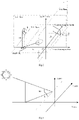
Fig. 2 is a schematic diagram of a reference coordinate system in the embodiments of the present disclosure. -
Fig. 3 is a schematic diagram of a sun altitude angle and a sun azimuth angle in the embodiments of the present disclosure. -
Fig. 4 is a detailed flowchart of embodiments of the present disclosure. -
Fig. 5 is a solution method flowchart of a yaw-prohibited area in the embodiments of the present disclosure. - The present disclosure will be further described with reference to figures and embodiments below.
- A method is provided for controlling shadow flickers of a wind turbine as show in
Figs. 1-5 , including: - in a Step 1, acquiring a current time of a wind farm;
- in a Step 2, calculating a yaw-prohibited area that is affected by shadow flickers at the current moment. The specific steps are as follows:
in a Step 2.1: building a reference coordinatesystem 0, and proceeding to a Step 2.2; wherein Step 2.1 is specified as:- in a Step 2.1.1: building an X-Y plane in a horizontal plane where the lowest point of the sensitive area Ψ is located, wherein the sensitive area Ψ to be determined is a potential area impacted by shadow flickers; and proceeding to a Step 2.1.2;
- in Step 2.1.2: building a Y-Z plane in a south-north vertical plane where a centric point of the sensitive area Ψ is located; and proceeding to a Step 2.1.3;
- in Step 2.1.3: building an X-Z plane in an east-west vertical plane where a centric point of the yaw rotation is located; and proceeding to a Step 2.1.4;
- in Step 2.1.4: taking an X axis as an intersecting line between the X-Y plane and the X-Z plane, and East as a positive direction; and proceeding to a Step 2.1.5;
- in Step 2.1.5: taking a Y axis as an intersecting line between the X-Y plane and the Y-Z plane, and North as a positive direction; and proceeding to a Step 2.1.6;
- in Step 2.1.6: taking a Z axis as an intersecting line between the X-Z plane and the Y-Z plane, and a top direction as a positive direction; and proceeding to Step 2.2;
- in Step 2.2: obtaining a yaw rotation centric coordinate point P, a rotor swept area radius R, and a distance R0 from the rotor swept area center to the yaw rotation center, wherein the rotor swept area is a blade surface that a blade sweeps about a rotation center; and proceeding to a Step 2.3;
- in Step 2.3: determining whether a sun light exposure intensity i is larger or equal to a light intensity threshold I, and, if so, proceeding to a Step 2.4, or keeping the wind turbine running if not;
- in Step 2.4: according to geographical knowledge, calculating a sun altitude angle h0 and a sun azimuth angle A at the current time t, and proceeding to a Step 2.5; and
- in Step 2.5: calculating the yaw-prohibited area Φ meeting the light intensity condition. Step 2.5 is specified as follows:
- in a Step 2.5.1: initializing Φ =ø, and initializing S=ø, wherein S is the intersection of the rotor swept area projection area and the sensitive area; and proceeding to a Step 2.5.2;
- in Step 2.5.2: checking through all angles Angle_At' within [0,2π], wherein Angle_At' is a yaw angle between the rotor swept area and the south direction and taking the clockwise direction as the positive direction; and proceeding to a Step 2.5.3;
- in Step 2.5.3: assuming the yaw angle as Angle_At', and calculating the space Ωt at the projection boundary of the rotor swept area impacting the sensitive area as:


- wherein θ represents a calculation angle, Dx represents a coordinate of the yaw rotation center on the X axis, Dh represents a height of the yaw rotation center, r_h represents a height of the sensitive area Ψ; and
- proceeding to a Step 2.5.4;
- in Step 2.5.4: assuming the yaw angle as Angle_At', and checking through all points within the sensitive area, wherein if the point


- wherein Xg is an X axis coordinate component in the sensitive area; Yg is an Y axis coordinate component in the sensitive area; Zg is an Z axis coordinate component in the sensitive area; r_l is a length of the sensitive area Ψ; Angle rl is an angle between a direction where the sensitive area Ψ heads to and the east-west direction, and the clockwise direction is taken as the positive direction; Dy is the coordinate of the sensitive area center on the Y axis; and
- proceeding to a Step 2.5.5;
- in Step 2.5.5: the yaw-prohibited area Φ={Angle_At'|when the yaw is at Angle_At', S ≠ø}; and proceeding to Step 3.
- in a Step 3, acquiring a current yaw angle of the wind turbine, and calculating a yaw-allowable area according to the yaw angle. The specific steps are as follows:
- in a Step 3.1: obtaining an allowable yaw amplitude Angle_a based on the wind turbine running status, and proceeding to a Step 3.2;
- in Step 3.2: the yaw-allowable area ξ={α|α∈[Angle_At-Angle_a,Angle_At+Angle_a]}, and proceeding to a Step 4.
- in Step 4, determining and selecting measures to avoid the influence of shadow flickers according to the current yaw angle as well as the relationship between the yaw-prohibited area and the yaw-allowable area. The determination and selection measures to prevent the light and shadow influence in Step 4 are specified as follows:
Determining whether the current yaw angle is in the yaw-prohibited area or not, and keeping the wind turbine running if not, or otherwise, if yes, continuing to determine if the yaw-allowable area is included in the yaw-prohibited area and, if so, shutting down the wind turbine, or otherwise, if the yaw-allowable area is incompletely included in the yaw-prohibited area, adjusting the yaw angle to depart from the yaw-prohibited area and keeping the wind turbine running.
Claims (3)
- A method for controlling shadow flickers of a wind turbine, comprising:in a Step 1, acquiring a current time of a wind farm;in a Step 2, calculating a yaw-prohibited area that is affected by shadow flickers at the current time;in a Step 3, acquiring a current yaw angle of the wind turbine, and calculating a yaw-allowable area according to the yaw angle; andin a Step 4, determining and selecting measures to avoid the influence of shadow flickers according to the current yaw angle as well as the relationship between the yaw-prohibited area and the yaw-allowable area, whereinStep 2 comprises the following steps:in a Step 2.1: building a reference coordinate system 0, and proceeding to a Step 2.2;in Step 2.2: obtaining a yaw rotation centric coordinate point P, a rotor swept area radius R, and a distance R0 from the rotor swept area center to the yaw rotation center, wherein the rotor swept area is a blade surface that a blade sweeps about a rotation center; and proceeding to a Step 2.3;in Step 2.3: determining whether a sun light exposure intensity i is larger or equal to a light intensity threshold I, and, if so, proceeding to a Step 2.4, or keeping the wind turbine running if not;in Step 2.4: calculating a sun altitude angle h0 and a sun azimuth angle A at the current time t, and proceeding to a Step 2.5; andin Step 2.5: calculating the yaw-prohibited area Φ meeting the light intensity condition,wherein,
Step 2.1 comprises the following steps:in a Step 2.1.1: building an X-Y plane in a horizontal plane where the lowest point of the sensitive area Ψ is located, wherein the sensitive area Ψ to be determined is a potential area impacted by shadow flickers; and proceeding to a Step 2.1.2;in Step 2.1.2: building a Y-Z plane in a south-north vertical plane where a centric point of the sensitive area Ψ is located; and proceeding to a Step 2.1.3;in Step 2.1.3: building an X-Z plane in an east-west vertical plane where a centric point of the yaw rotation is located; and proceeding to a Step 2.1.4;in Step 2.1.4: taking an X axis as an intersecting line between the X-Y plane and the X-Z plane, and East as a positive direction; and proceeding to a Step 2.1.5;in Step 2.1.5: taking a Y axis as an intersecting line between the X-Y plane and the Y-Z plane, and North as a positive direction; and proceeding to a Step 2.1.6; andin Step 2.1.6: taking a Z axis as an intersecting line between the X-Z plane and the Y-Z plane, and a top direction as a positive direction; and proceeding to Step 2.2;Step 2.5 comprises the following steps:in a Step 2.5.1: initializing Φ=ø, and initializing S=ø, wherein S is the intersection of the rotor swept area projection area and the sensitive area; and proceeding to a Step 2.5.2;in Step 2.5.2: checking through all angles Angle_At' within [0,2π], wherein Angle_At' is a yaw angle between the rotor swept area and the south direction and taking the clockwise direction as the positive direction; and proceeding to a Step 2.5.3;in Step 2.5.3: assuming the yaw angle as Angle_At', and calculating the space Ωt at the projection boundary of the rotor swept area impacting the sensitive area as:

 wherein θ represents a calculation angle, Dx represents a coordinate of the yaw rotation center on the X axis, Dh represents a height of the yaw rotation center, r_h represents a height of the sensitive area Ψ; and proceeding to a Step 2.5.4;in Step 2.5.4: assuming the yaw angle as Angle_At', and checking through all points within the sensitive area, wherein if the point
 wherein Xg is an X axis coordinate component in the sensitive area; Yg is an Y axis coordinate component in the sensitive area; Zg is an Z axis coordinate component in the sensitive area; r_l is a length of the sensitive area Ψ; Angle rl is an angle between a direction where the sensitive area Ψ heads to and the east-west direction, and the clockwise direction is taken as the positive direction; Dy is the coordinate of the sensitive area center on the Y axis; and proceeding to a Step 2.5.5; andin Step 2.5.5: the yaw-prohibited area Φ={ Angle_At'|when the yaw is at Angle_At', S≠ø}; and proceeding to Step 3.
 - The method for controlling shadow flickers of the wind turbine according to claim 1, wherein Step 3 includes:in a Step 3.1: obtaining the allowable yaw amplitude of Angle_a based on the wind turbine running status, and proceeding to a Step 3.2; andin Step 3.2: the yaw-allowable area ξ={α|α∈[Angle_At'-Angle_a,Angle_At'+Angle_a]}, and proceeding to Step 4.
- The method for controlling shadow flickers of the wind turbine according to claim 1, wherein the determination and selection measures to prevent the light and shadow influence in Step 4 include:
determining whether the current yaw angle is in the yaw-prohibited area or not, and keeping the wind turbine running if not, or otherwise, if yes, continuing to determine if the yaw-allowable area is included in the yaw-prohibited area and, if so, shutting down the wind turbine, or otherwise, if the yaw-allowable area is incompletely included in the yaw-prohibited area, adjusting the yaw angle to depart from the yaw-prohibited area and keeping the wind turbine running.
Applications Claiming Priority (2)
| Application Number | Priority Date | Filing Date | Title |
|---|---|---|---|
| CN201911300326.5A CN110778466B (en) | 2019-12-17 | 2019-12-17 | A light and shadow flicker control method for wind turbines |
| PCT/CN2020/125135 WO2021120885A1 (en) | 2019-12-17 | 2020-10-30 | Light and shadow flicker control method for wind turbine generator system |
Publications (3)
| Publication Number | Publication Date |
|---|---|
| EP3862564A1 EP3862564A1 (en) | 2021-08-11 |
| EP3862564A4 EP3862564A4 (en) | 2021-11-10 |
| EP3862564B1 true EP3862564B1 (en) | 2023-01-04 |
Family
ID=69394616
Family Applications (1)
| Application Number | Title | Priority Date | Filing Date |
|---|---|---|---|
| EP20848778.5A Active EP3862564B1 (en) | 2019-12-17 | 2020-10-30 | Light and shadow flicker control method for wind turbine generator system |
Country Status (3)
| Country | Link |
|---|---|
| EP (1) | EP3862564B1 (en) |
| CN (1) | CN110778466B (en) |
| WO (1) | WO2021120885A1 (en) |
Families Citing this family (6)
| Publication number | Priority date | Publication date | Assignee | Title |
|---|---|---|---|---|
| CN110778466B (en) * | 2019-12-17 | 2020-08-28 | 湘电风能有限公司 | A light and shadow flicker control method for wind turbines |
| CN111520284A (en) * | 2020-05-09 | 2020-08-11 | 中国船舶重工集团海装风电股份有限公司 | Light and shadow control method, device, equipment and medium for wind turbine |
| CN112555097B (en) * | 2020-12-08 | 2022-04-01 | 东方电气风电股份有限公司 | Method for preventing wind turbine generator from polluting residents' residences by light and shadow |
| CN114810516B (en) * | 2022-03-21 | 2025-06-17 | 运达能源科技集团股份有限公司 | A method for reducing the impact of wind turbine light and shadow on surrounding residents by yaw |
| CN116658367A (en) * | 2023-07-19 | 2023-08-29 | 中国华能集团清洁能源技术研究院有限公司 | A method and system for monitoring and controlling light and shadow pollution of distributed wind power generators |
| CN119616792B (en) * | 2024-12-02 | 2025-07-18 | 运达能源科技集团股份有限公司 | A wind farm light and shadow effect evaluation method, device and medium |
Family Cites Families (12)
| Publication number | Priority date | Publication date | Assignee | Title |
|---|---|---|---|---|
| JP4585151B2 (en) * | 2001-07-26 | 2010-11-24 | 富士重工業株式会社 | Wind generator operation control method |
| JP4411015B2 (en) * | 2003-06-03 | 2010-02-10 | 富士重工業株式会社 | Wind power generator |
| US8310075B2 (en) * | 2007-09-03 | 2012-11-13 | Vestas Wind Systems A/S | Shadow control of wind turbines |
| EP2554836B1 (en) * | 2011-08-03 | 2014-05-07 | Alstom Renovables España, S.L. | Shadow flicker measurement system, wind turbine comprising such a system, and control method using such a system |
| CN103590975B (en) * | 2013-11-23 | 2017-03-29 | 大连尚能科技发展有限公司 | An environment-friendly wind turbine control system and method |
| JP6347671B2 (en) * | 2014-05-23 | 2018-06-27 | 三菱重工業株式会社 | Renewable energy generator |
| CN105069274B (en) * | 2015-06-29 | 2018-10-09 | 华北水利水电大学 | Method is determined based on the atural object screening of effectively blocking of sunshine space-time characteristic |
| CN105673359B (en) * | 2016-01-06 | 2018-08-03 | 北京金风科创风电设备有限公司 | Wind power plant shadow evaluation method, device and system |
| CN107654335B (en) * | 2016-07-26 | 2018-12-07 | 北京金风科创风电设备有限公司 | Yaw control method and device of wind generating set |
| US10612521B2 (en) * | 2018-03-05 | 2020-04-07 | General Electric Company | Wind turbine shadow flicker management system |
| CN110318955B (en) * | 2019-06-14 | 2021-05-14 | 西昌飓源风电开发有限公司 | Blade shadow influence scope monitoring device for land wind generating set |
| CN110778466B (en) * | 2019-12-17 | 2020-08-28 | 湘电风能有限公司 | A light and shadow flicker control method for wind turbines |
-
2019
- 2019-12-17 CN CN201911300326.5A patent/CN110778466B/en active Active
-
2020
- 2020-10-30 WO PCT/CN2020/125135 patent/WO2021120885A1/en not_active Ceased
- 2020-10-30 EP EP20848778.5A patent/EP3862564B1/en active Active
Also Published As
| Publication number | Publication date |
|---|---|
| CN110778466A (en) | 2020-02-11 |
| EP3862564A1 (en) | 2021-08-11 |
| WO2021120885A1 (en) | 2021-06-24 |
| EP3862564A4 (en) | 2021-11-10 |
| CN110778466B (en) | 2020-08-28 |
Similar Documents
| Publication | Publication Date | Title |
|---|---|---|
| EP3862564A1 (en) | Light and shadow flicker control method for wind turbine generator system | |
| US7812471B2 (en) | Method of operating a wind power station | |
| US10458091B2 (en) | Pile driving machine | |
| AU2006220427B2 (en) | Method for adapting a wind energy installation to given wind conditions | |
| US8105028B2 (en) | Systems and methods for mitigating the effects of wind turbines on radar | |
| KR101216206B1 (en) | Solar tracker apparatus and method of inland waters | |
| US20090185900A1 (en) | Wind-driven electricity generation device, method of controlling wind-driven electricity generation device, and computer program | |
| DK2599993T3 (en) | A method for determining krøjningsvinklen of a component of a wind turbine | |
| AU2017374057B2 (en) | Enclosure and dynamic heat dissipation method for heat source inside the enclosure and dynamic heat dissipation system inside the enclosure | |
| US9261075B2 (en) | Wind turbine shadow flicker protection system having a driving mechanism allowing a single light sensor to receive light at different times and directions | |
| CN103019261A (en) | Method for calibrating and detecting azimuth angle of double-shaft tracking heliostat | |
| CN111971476A (en) | Wind power plant, wind farm, and method for regulating a wind power plant and a wind farm | |
| EP2554836B1 (en) | Shadow flicker measurement system, wind turbine comprising such a system, and control method using such a system | |
| RS54942B1 (en) | PROCEDURE FOR CONTROL OF THE WIND POWER PLANT AND THE WIND POWER PLANT | |
| CN118611767A (en) | A solar eclipse avoidance system and method for a laser communication ground station | |
| JP4585151B2 (en) | Wind generator operation control method | |
| WO2022096363A1 (en) | Method for computer-implemented operation of a wind turbine | |
| CN112555097B (en) | Method for preventing wind turbine generator from polluting residents' residences by light and shadow | |
| US11028829B2 (en) | Controlling wind turbine based on rain drop size | |
| WO2013017646A1 (en) | Shadow flicker measurement system, wind turbine comprising such a system, and method using such a system | |
| ES2927184T3 (en) | Method and arrangement for detecting a shadow condition of a wind turbine | |
| CN114810516B (en) | A method for reducing the impact of wind turbine light and shadow on surrounding residents by yaw | |
| US20210404442A1 (en) | Method for determining shadow flicker from a wind turbine system | |
| CN109407132A (en) | A kind of unmanned plane Radiation monitoring method and system | |
| WO2026054692A1 (en) | Solar panel system(s) and method(s) for vertical tracking |
Legal Events
| Date | Code | Title | Description |
|---|---|---|---|
| STAA | Information on the status of an ep patent application or granted ep patent |
Free format text: STATUS: UNKNOWN |
|
| STAA | Information on the status of an ep patent application or granted ep patent |
Free format text: STATUS: THE INTERNATIONAL PUBLICATION HAS BEEN MADE |
|
| PUAI | Public reference made under article 153(3) epc to a published international application that has entered the european phase |
Free format text: ORIGINAL CODE: 0009012 |
|
| STAA | Information on the status of an ep patent application or granted ep patent |
Free format text: STATUS: REQUEST FOR EXAMINATION WAS MADE |
|
| 17P | Request for examination filed |
Effective date: 20210308 |
|
| AK | Designated contracting states |
Kind code of ref document: A1 Designated state(s): AL AT BE BG CH CY CZ DE DK EE ES FI FR GB GR HR HU IE IS IT LI LT LU LV MC MK MT NL NO PL PT RO RS SE SI SK SM TR |
|
| A4 | Supplementary search report drawn up and despatched |
Effective date: 20211008 |
|
| RIC1 | Information provided on ipc code assigned before grant |
Ipc: F03D 80/20 20160101AFI20211004BHEP |
|
| GRAP | Despatch of communication of intention to grant a patent |
Free format text: ORIGINAL CODE: EPIDOSNIGR1 |
|
| STAA | Information on the status of an ep patent application or granted ep patent |
Free format text: STATUS: GRANT OF PATENT IS INTENDED |
|
| INTG | Intention to grant announced |
Effective date: 20220727 |
|
| GRAS | Grant fee paid |
Free format text: ORIGINAL CODE: EPIDOSNIGR3 |
|
| GRAA | (expected) grant |
Free format text: ORIGINAL CODE: 0009210 |
|
| STAA | Information on the status of an ep patent application or granted ep patent |
Free format text: STATUS: THE PATENT HAS BEEN GRANTED |
|
| DAV | Request for validation of the european patent (deleted) | ||
| DAX | Request for extension of the european patent (deleted) | ||
| AK | Designated contracting states |
Kind code of ref document: B1 Designated state(s): AL AT BE BG CH CY CZ DE DK EE ES FI FR GB GR HR HU IE IS IT LI LT LU LV MC MK MT NL NO PL PT RO RS SE SI SK SM TR |
|
| REG | Reference to a national code |
Ref country code: GB Ref legal event code: FG4D |
|
| REG | Reference to a national code |
Ref country code: DE Ref legal event code: R096 Ref document number: 602020007414 Country of ref document: DE |
|
| REG | Reference to a national code |
Ref country code: CH Ref legal event code: EP |
|
| REG | Reference to a national code |
Ref country code: AT Ref legal event code: REF Ref document number: 1542112 Country of ref document: AT Kind code of ref document: T Effective date: 20230115 |
|
| REG | Reference to a national code |
Ref country code: IE Ref legal event code: FG4D |
|
| REG | Reference to a national code |
Ref country code: LT Ref legal event code: MG9D |
|
| REG | Reference to a national code |
Ref country code: NL Ref legal event code: MP Effective date: 20230104 |
|
| REG | Reference to a national code |
Ref country code: AT Ref legal event code: MK05 Ref document number: 1542112 Country of ref document: AT Kind code of ref document: T Effective date: 20230104 |
|
| PG25 | Lapsed in a contracting state [announced via postgrant information from national office to epo] |
Ref country code: NL Free format text: LAPSE BECAUSE OF FAILURE TO SUBMIT A TRANSLATION OF THE DESCRIPTION OR TO PAY THE FEE WITHIN THE PRESCRIBED TIME-LIMIT Effective date: 20230104 |
|
| PG25 | Lapsed in a contracting state [announced via postgrant information from national office to epo] |
Ref country code: RS Free format text: LAPSE BECAUSE OF FAILURE TO SUBMIT A TRANSLATION OF THE DESCRIPTION OR TO PAY THE FEE WITHIN THE PRESCRIBED TIME-LIMIT Effective date: 20230104 Ref country code: PT Free format text: LAPSE BECAUSE OF FAILURE TO SUBMIT A TRANSLATION OF THE DESCRIPTION OR TO PAY THE FEE WITHIN THE PRESCRIBED TIME-LIMIT Effective date: 20230504 Ref country code: NO Free format text: LAPSE BECAUSE OF FAILURE TO SUBMIT A TRANSLATION OF THE DESCRIPTION OR TO PAY THE FEE WITHIN THE PRESCRIBED TIME-LIMIT Effective date: 20230404 Ref country code: LV Free format text: LAPSE BECAUSE OF FAILURE TO SUBMIT A TRANSLATION OF THE DESCRIPTION OR TO PAY THE FEE WITHIN THE PRESCRIBED TIME-LIMIT Effective date: 20230104 Ref country code: LT Free format text: LAPSE BECAUSE OF FAILURE TO SUBMIT A TRANSLATION OF THE DESCRIPTION OR TO PAY THE FEE WITHIN THE PRESCRIBED TIME-LIMIT Effective date: 20230104 Ref country code: HR Free format text: LAPSE BECAUSE OF FAILURE TO SUBMIT A TRANSLATION OF THE DESCRIPTION OR TO PAY THE FEE WITHIN THE PRESCRIBED TIME-LIMIT Effective date: 20230104 Ref country code: ES Free format text: LAPSE BECAUSE OF FAILURE TO SUBMIT A TRANSLATION OF THE DESCRIPTION OR TO PAY THE FEE WITHIN THE PRESCRIBED TIME-LIMIT Effective date: 20230104 Ref country code: AT Free format text: LAPSE BECAUSE OF FAILURE TO SUBMIT A TRANSLATION OF THE DESCRIPTION OR TO PAY THE FEE WITHIN THE PRESCRIBED TIME-LIMIT Effective date: 20230104 |
|
| PG25 | Lapsed in a contracting state [announced via postgrant information from national office to epo] |
Ref country code: SE Free format text: LAPSE BECAUSE OF FAILURE TO SUBMIT A TRANSLATION OF THE DESCRIPTION OR TO PAY THE FEE WITHIN THE PRESCRIBED TIME-LIMIT Effective date: 20230104 Ref country code: PL Free format text: LAPSE BECAUSE OF FAILURE TO SUBMIT A TRANSLATION OF THE DESCRIPTION OR TO PAY THE FEE WITHIN THE PRESCRIBED TIME-LIMIT Effective date: 20230104 Ref country code: IS Free format text: LAPSE BECAUSE OF FAILURE TO SUBMIT A TRANSLATION OF THE DESCRIPTION OR TO PAY THE FEE WITHIN THE PRESCRIBED TIME-LIMIT Effective date: 20230504 Ref country code: GR Free format text: LAPSE BECAUSE OF FAILURE TO SUBMIT A TRANSLATION OF THE DESCRIPTION OR TO PAY THE FEE WITHIN THE PRESCRIBED TIME-LIMIT Effective date: 20230405 Ref country code: FI Free format text: LAPSE BECAUSE OF FAILURE TO SUBMIT A TRANSLATION OF THE DESCRIPTION OR TO PAY THE FEE WITHIN THE PRESCRIBED TIME-LIMIT Effective date: 20230104 |
|
| REG | Reference to a national code |
Ref country code: DE Ref legal event code: R097 Ref document number: 602020007414 Country of ref document: DE |
|
| PG25 | Lapsed in a contracting state [announced via postgrant information from national office to epo] |
Ref country code: SM Free format text: LAPSE BECAUSE OF FAILURE TO SUBMIT A TRANSLATION OF THE DESCRIPTION OR TO PAY THE FEE WITHIN THE PRESCRIBED TIME-LIMIT Effective date: 20230104 Ref country code: RO Free format text: LAPSE BECAUSE OF FAILURE TO SUBMIT A TRANSLATION OF THE DESCRIPTION OR TO PAY THE FEE WITHIN THE PRESCRIBED TIME-LIMIT Effective date: 20230104 Ref country code: EE Free format text: LAPSE BECAUSE OF FAILURE TO SUBMIT A TRANSLATION OF THE DESCRIPTION OR TO PAY THE FEE WITHIN THE PRESCRIBED TIME-LIMIT Effective date: 20230104 Ref country code: DK Free format text: LAPSE BECAUSE OF FAILURE TO SUBMIT A TRANSLATION OF THE DESCRIPTION OR TO PAY THE FEE WITHIN THE PRESCRIBED TIME-LIMIT Effective date: 20230104 Ref country code: CZ Free format text: LAPSE BECAUSE OF FAILURE TO SUBMIT A TRANSLATION OF THE DESCRIPTION OR TO PAY THE FEE WITHIN THE PRESCRIBED TIME-LIMIT Effective date: 20230104 |
|
| PLBE | No opposition filed within time limit |
Free format text: ORIGINAL CODE: 0009261 |
|
| STAA | Information on the status of an ep patent application or granted ep patent |
Free format text: STATUS: NO OPPOSITION FILED WITHIN TIME LIMIT |
|
| PG25 | Lapsed in a contracting state [announced via postgrant information from national office to epo] |
Ref country code: SK Free format text: LAPSE BECAUSE OF FAILURE TO SUBMIT A TRANSLATION OF THE DESCRIPTION OR TO PAY THE FEE WITHIN THE PRESCRIBED TIME-LIMIT Effective date: 20230104 |
|
| 26N | No opposition filed |
Effective date: 20231005 |
|
| PG25 | Lapsed in a contracting state [announced via postgrant information from national office to epo] |
Ref country code: SI Free format text: LAPSE BECAUSE OF FAILURE TO SUBMIT A TRANSLATION OF THE DESCRIPTION OR TO PAY THE FEE WITHIN THE PRESCRIBED TIME-LIMIT Effective date: 20230104 |
|
| PG25 | Lapsed in a contracting state [announced via postgrant information from national office to epo] |
Ref country code: IT Free format text: LAPSE BECAUSE OF FAILURE TO SUBMIT A TRANSLATION OF THE DESCRIPTION OR TO PAY THE FEE WITHIN THE PRESCRIBED TIME-LIMIT Effective date: 20230104 Ref country code: MC Free format text: LAPSE BECAUSE OF FAILURE TO SUBMIT A TRANSLATION OF THE DESCRIPTION OR TO PAY THE FEE WITHIN THE PRESCRIBED TIME-LIMIT Effective date: 20230104 |
|
| REG | Reference to a national code |
Ref country code: CH Ref legal event code: PL |
|
| REG | Reference to a national code |
Ref country code: BE Ref legal event code: MM Effective date: 20231031 |
|
| PG25 | Lapsed in a contracting state [announced via postgrant information from national office to epo] |
Ref country code: LU Free format text: LAPSE BECAUSE OF NON-PAYMENT OF DUE FEES Effective date: 20231030 |
|
| PG25 | Lapsed in a contracting state [announced via postgrant information from national office to epo] |
Ref country code: LU Free format text: LAPSE BECAUSE OF NON-PAYMENT OF DUE FEES Effective date: 20231030 |
|
| PG25 | Lapsed in a contracting state [announced via postgrant information from national office to epo] |
Ref country code: CH Free format text: LAPSE BECAUSE OF NON-PAYMENT OF DUE FEES Effective date: 20231031 |
|
| PG25 | Lapsed in a contracting state [announced via postgrant information from national office to epo] |
Ref country code: FR Free format text: LAPSE BECAUSE OF NON-PAYMENT OF DUE FEES Effective date: 20231031 Ref country code: CH Free format text: LAPSE BECAUSE OF NON-PAYMENT OF DUE FEES Effective date: 20231031 |
|
| PG25 | Lapsed in a contracting state [announced via postgrant information from national office to epo] |
Ref country code: BE Free format text: LAPSE BECAUSE OF NON-PAYMENT OF DUE FEES Effective date: 20231031 |
|
| PG25 | Lapsed in a contracting state [announced via postgrant information from national office to epo] |
Ref country code: IE Free format text: LAPSE BECAUSE OF NON-PAYMENT OF DUE FEES Effective date: 20231030 |
|
| PG25 | Lapsed in a contracting state [announced via postgrant information from national office to epo] |
Ref country code: IE Free format text: LAPSE BECAUSE OF NON-PAYMENT OF DUE FEES Effective date: 20231030 |
|
| PG25 | Lapsed in a contracting state [announced via postgrant information from national office to epo] |
Ref country code: BG Free format text: LAPSE BECAUSE OF FAILURE TO SUBMIT A TRANSLATION OF THE DESCRIPTION OR TO PAY THE FEE WITHIN THE PRESCRIBED TIME-LIMIT Effective date: 20230104 |
|
| PG25 | Lapsed in a contracting state [announced via postgrant information from national office to epo] |
Ref country code: BG Free format text: LAPSE BECAUSE OF FAILURE TO SUBMIT A TRANSLATION OF THE DESCRIPTION OR TO PAY THE FEE WITHIN THE PRESCRIBED TIME-LIMIT Effective date: 20230104 |
|
| GBPC | Gb: european patent ceased through non-payment of renewal fee |
Effective date: 20241030 |
|
| PG25 | Lapsed in a contracting state [announced via postgrant information from national office to epo] |
Ref country code: GB Free format text: LAPSE BECAUSE OF NON-PAYMENT OF DUE FEES Effective date: 20241030 |
|
| PG25 | Lapsed in a contracting state [announced via postgrant information from national office to epo] |
Ref country code: CY Free format text: LAPSE BECAUSE OF FAILURE TO SUBMIT A TRANSLATION OF THE DESCRIPTION OR TO PAY THE FEE WITHIN THE PRESCRIBED TIME-LIMIT; INVALID AB INITIO Effective date: 20201030 |
|
| PG25 | Lapsed in a contracting state [announced via postgrant information from national office to epo] |
Ref country code: HU Free format text: LAPSE BECAUSE OF FAILURE TO SUBMIT A TRANSLATION OF THE DESCRIPTION OR TO PAY THE FEE WITHIN THE PRESCRIBED TIME-LIMIT; INVALID AB INITIO Effective date: 20201030 |
|
| PG25 | Lapsed in a contracting state [announced via postgrant information from national office to epo] |
Ref country code: TR Free format text: LAPSE BECAUSE OF FAILURE TO SUBMIT A TRANSLATION OF THE DESCRIPTION OR TO PAY THE FEE WITHIN THE PRESCRIBED TIME-LIMIT Effective date: 20230104 |
|
| PGFP | Annual fee paid to national office [announced via postgrant information from national office to epo] |
Ref country code: DE Payment date: 20260129 Year of fee payment: 6 |