EP3862558A1 - Pitch control of a wind turbine based position data from position localization sensors - Google Patents
Pitch control of a wind turbine based position data from position localization sensors Download PDFInfo
- Publication number
- EP3862558A1 EP3862558A1 EP21155551.1A EP21155551A EP3862558A1 EP 3862558 A1 EP3862558 A1 EP 3862558A1 EP 21155551 A EP21155551 A EP 21155551A EP 3862558 A1 EP3862558 A1 EP 3862558A1
- Authority
- EP
- European Patent Office
- Prior art keywords
- rotor blade
- sensors
- pitch
- blade
- controller
- Prior art date
- Legal status (The legal status is an assumption and is not a legal conclusion. Google has not performed a legal analysis and makes no representation as to the accuracy of the status listed.)
- Granted
Links
Images



Classifications
-
- F—MECHANICAL ENGINEERING; LIGHTING; HEATING; WEAPONS; BLASTING
- F03—MACHINES OR ENGINES FOR LIQUIDS; WIND, SPRING, OR WEIGHT MOTORS; PRODUCING MECHANICAL POWER OR A REACTIVE PROPULSIVE THRUST, NOT OTHERWISE PROVIDED FOR
- F03D—WIND MOTORS
- F03D7/00—Controlling wind motors
- F03D7/02—Controlling wind motors the wind motors having rotation axis substantially parallel to the air flow entering the rotor
- F03D7/0204—Controlling wind motors the wind motors having rotation axis substantially parallel to the air flow entering the rotor for orientation in relation to wind direction
-
- F—MECHANICAL ENGINEERING; LIGHTING; HEATING; WEAPONS; BLASTING
- F03—MACHINES OR ENGINES FOR LIQUIDS; WIND, SPRING, OR WEIGHT MOTORS; PRODUCING MECHANICAL POWER OR A REACTIVE PROPULSIVE THRUST, NOT OTHERWISE PROVIDED FOR
- F03D—WIND MOTORS
- F03D7/00—Controlling wind motors
- F03D7/02—Controlling wind motors the wind motors having rotation axis substantially parallel to the air flow entering the rotor
- F03D7/022—Adjusting aerodynamic properties of the blades
- F03D7/0224—Adjusting blade pitch
-
- F—MECHANICAL ENGINEERING; LIGHTING; HEATING; WEAPONS; BLASTING
- F03—MACHINES OR ENGINES FOR LIQUIDS; WIND, SPRING, OR WEIGHT MOTORS; PRODUCING MECHANICAL POWER OR A REACTIVE PROPULSIVE THRUST, NOT OTHERWISE PROVIDED FOR
- F03D—WIND MOTORS
- F03D17/00—Monitoring or testing of wind motors, e.g. diagnostics
-
- F—MECHANICAL ENGINEERING; LIGHTING; HEATING; WEAPONS; BLASTING
- F03—MACHINES OR ENGINES FOR LIQUIDS; WIND, SPRING, OR WEIGHT MOTORS; PRODUCING MECHANICAL POWER OR A REACTIVE PROPULSIVE THRUST, NOT OTHERWISE PROVIDED FOR
- F03D—WIND MOTORS
- F03D7/00—Controlling wind motors
- F03D7/02—Controlling wind motors the wind motors having rotation axis substantially parallel to the air flow entering the rotor
- F03D7/022—Adjusting aerodynamic properties of the blades
- F03D7/024—Adjusting aerodynamic properties of the blades of individual blades
-
- F—MECHANICAL ENGINEERING; LIGHTING; HEATING; WEAPONS; BLASTING
- F03—MACHINES OR ENGINES FOR LIQUIDS; WIND, SPRING, OR WEIGHT MOTORS; PRODUCING MECHANICAL POWER OR A REACTIVE PROPULSIVE THRUST, NOT OTHERWISE PROVIDED FOR
- F03D—WIND MOTORS
- F03D7/00—Controlling wind motors
- F03D7/02—Controlling wind motors the wind motors having rotation axis substantially parallel to the air flow entering the rotor
- F03D7/028—Controlling wind motors the wind motors having rotation axis substantially parallel to the air flow entering the rotor controlling wind motor output power
- F03D7/0288—Controlling wind motors the wind motors having rotation axis substantially parallel to the air flow entering the rotor controlling wind motor output power in relation to clearance between the blade and the tower, i.e. preventing tower strike
-
- F—MECHANICAL ENGINEERING; LIGHTING; HEATING; WEAPONS; BLASTING
- F03—MACHINES OR ENGINES FOR LIQUIDS; WIND, SPRING, OR WEIGHT MOTORS; PRODUCING MECHANICAL POWER OR A REACTIVE PROPULSIVE THRUST, NOT OTHERWISE PROVIDED FOR
- F03D—WIND MOTORS
- F03D7/00—Controlling wind motors
- F03D7/02—Controlling wind motors the wind motors having rotation axis substantially parallel to the air flow entering the rotor
- F03D7/04—Automatic control; Regulation
- F03D7/042—Automatic control; Regulation by means of an electrical or electronic controller
- F03D7/043—Automatic control; Regulation by means of an electrical or electronic controller characterised by the type of control logic
- F03D7/045—Automatic control; Regulation by means of an electrical or electronic controller characterised by the type of control logic with model-based controls
-
- F—MECHANICAL ENGINEERING; LIGHTING; HEATING; WEAPONS; BLASTING
- F03—MACHINES OR ENGINES FOR LIQUIDS; WIND, SPRING, OR WEIGHT MOTORS; PRODUCING MECHANICAL POWER OR A REACTIVE PROPULSIVE THRUST, NOT OTHERWISE PROVIDED FOR
- F03D—WIND MOTORS
- F03D7/00—Controlling wind motors
- F03D7/02—Controlling wind motors the wind motors having rotation axis substantially parallel to the air flow entering the rotor
- F03D7/04—Automatic control; Regulation
- F03D7/042—Automatic control; Regulation by means of an electrical or electronic controller
- F03D7/043—Automatic control; Regulation by means of an electrical or electronic controller characterised by the type of control logic
- F03D7/046—Automatic control; Regulation by means of an electrical or electronic controller characterised by the type of control logic with learning or adaptive control, e.g. self-tuning, fuzzy logic or neural network
-
- F—MECHANICAL ENGINEERING; LIGHTING; HEATING; WEAPONS; BLASTING
- F03—MACHINES OR ENGINES FOR LIQUIDS; WIND, SPRING, OR WEIGHT MOTORS; PRODUCING MECHANICAL POWER OR A REACTIVE PROPULSIVE THRUST, NOT OTHERWISE PROVIDED FOR
- F03D—WIND MOTORS
- F03D7/00—Controlling wind motors
- F03D7/02—Controlling wind motors the wind motors having rotation axis substantially parallel to the air flow entering the rotor
- F03D7/04—Automatic control; Regulation
- F03D7/042—Automatic control; Regulation by means of an electrical or electronic controller
- F03D7/047—Automatic control; Regulation by means of an electrical or electronic controller characterised by the controller architecture, e.g. multiple processors or data communications
-
- F—MECHANICAL ENGINEERING; LIGHTING; HEATING; WEAPONS; BLASTING
- F03—MACHINES OR ENGINES FOR LIQUIDS; WIND, SPRING, OR WEIGHT MOTORS; PRODUCING MECHANICAL POWER OR A REACTIVE PROPULSIVE THRUST, NOT OTHERWISE PROVIDED FOR
- F03D—WIND MOTORS
- F03D7/00—Controlling wind motors
- F03D7/02—Controlling wind motors the wind motors having rotation axis substantially parallel to the air flow entering the rotor
- F03D7/04—Automatic control; Regulation
- F03D7/042—Automatic control; Regulation by means of an electrical or electronic controller
- F03D7/048—Automatic control; Regulation by means of an electrical or electronic controller controlling wind farms
-
- F—MECHANICAL ENGINEERING; LIGHTING; HEATING; WEAPONS; BLASTING
- F05—INDEXING SCHEMES RELATING TO ENGINES OR PUMPS IN VARIOUS SUBCLASSES OF CLASSES F01-F04
- F05B—INDEXING SCHEME RELATING TO WIND, SPRING, WEIGHT, INERTIA OR LIKE MOTORS, TO MACHINES OR ENGINES FOR LIQUIDS COVERED BY SUBCLASSES F03B, F03D AND F03G
- F05B2270/00—Control
- F05B2270/10—Purpose of the control system
- F05B2270/17—Purpose of the control system to avoid excessive deflection of the blades
-
- F—MECHANICAL ENGINEERING; LIGHTING; HEATING; WEAPONS; BLASTING
- F05—INDEXING SCHEMES RELATING TO ENGINES OR PUMPS IN VARIOUS SUBCLASSES OF CLASSES F01-F04
- F05B—INDEXING SCHEME RELATING TO WIND, SPRING, WEIGHT, INERTIA OR LIKE MOTORS, TO MACHINES OR ENGINES FOR LIQUIDS COVERED BY SUBCLASSES F03B, F03D AND F03G
- F05B2270/00—Control
- F05B2270/30—Control parameters, e.g. input parameters
- F05B2270/33—Proximity of blade to tower
-
- F—MECHANICAL ENGINEERING; LIGHTING; HEATING; WEAPONS; BLASTING
- F05—INDEXING SCHEMES RELATING TO ENGINES OR PUMPS IN VARIOUS SUBCLASSES OF CLASSES F01-F04
- F05B—INDEXING SCHEME RELATING TO WIND, SPRING, WEIGHT, INERTIA OR LIKE MOTORS, TO MACHINES OR ENGINES FOR LIQUIDS COVERED BY SUBCLASSES F03B, F03D AND F03G
- F05B2270/00—Control
- F05B2270/70—Type of control algorithm
- F05B2270/707—Type of control algorithm fuzzy logic
-
- Y—GENERAL TAGGING OF NEW TECHNOLOGICAL DEVELOPMENTS; GENERAL TAGGING OF CROSS-SECTIONAL TECHNOLOGIES SPANNING OVER SEVERAL SECTIONS OF THE IPC; TECHNICAL SUBJECTS COVERED BY FORMER USPC CROSS-REFERENCE ART COLLECTIONS [XRACs] AND DIGESTS
- Y02—TECHNOLOGIES OR APPLICATIONS FOR MITIGATION OR ADAPTATION AGAINST CLIMATE CHANGE
- Y02E—REDUCTION OF GREENHOUSE GAS [GHG] EMISSIONS, RELATED TO ENERGY GENERATION, TRANSMISSION OR DISTRIBUTION
- Y02E10/00—Energy generation through renewable energy sources
- Y02E10/70—Wind energy
- Y02E10/72—Wind turbines with rotation axis in wind direction
Definitions
- the present disclosure relates generally to wind turbines, and more specifically, to systems and methods for controlling pitch and/or pitch misalignment of a wind turbine using position data from position localization sensors, such as real-time kinematic (RTK) sensors.
- position localization sensors such as real-time kinematic (RTK) sensors.
- Wind power is considered one of the cleanest, most environmentally friendly energy sources presently available, and wind turbines have gained increased attention in this regard.
- a modern wind turbine typically includes a tower, generator, gearbox, nacelle, and one or more rotor blades.
- the rotor blades capture kinetic energy from wind using known foil principles and transmit the kinetic energy through rotational energy to turn a shaft coupling the rotor blades to a gearbox, or if a gearbox is not used, directly to the generator.
- the generator then converts the mechanical energy to electrical energy that may be deployed to a utility grid.
- Such configurations may also include power converters that are used to convert a frequency of generated electric power to a frequency substantially similar to a utility grid frequency.
- various sensor systems are employed to monitor various conditions of the rotor blades.
- such conditions may include loading and/or pitch alignment, which can have a negative impact on the annual energy production (AEP) of the wind turbine.
- AEP annual energy production
- a plurality of proximity sensors are installed on the main shaft to measure various moments of the rotor blades.
- a plurality of strain sensors are installed on the rotor blades to measure individual blade root bending moments. More particularly, the strain signals from the strain sensors are converted into bending moments.
- Such sensors tend to experience performance degradation and drift over time and require continued calibration.
- the art is continuously seeking new and improved systems and methods for controlling pitch and/or pitch misalignment of a wind turbine. Accordingly, the present disclosure is directed to systems and methods for controlling pitch and/or pitch misalignment of a wind turbine using position data from position localization sensors, such as real-time kinematic (RTK) sensors.
- position localization sensors such as real-time kinematic (RTK) sensors.
- the present disclosure is directed to a method for controlling pitching of at least one rotor blade of a wind turbine.
- the method includes receiving, via one or more position localization sensors, position data relating to the at least one rotor blade of the wind turbine. Further, the method includes determining, via a controller, a blade deflection signal of the at least one rotor blade based on the position data. Moreover, the method includes determining, via a computer-implemented model stored in the controller, a pitch command for the at least one rotor blade as a function of the blade deflection signal and an azimuth angle of the at least one rotor blade.
- the position localization sensor(s) may include one or more of the following: one or more real-time kinematic (RTK) sensors, one or more inertial navigation system (INS) sensors, one or more global positioning system (GPS) sensors, or combinations thereof.
- RTK real-time kinematic
- INS inertial navigation system
- GPS global positioning system
- the position localization sensor(s) may include the RTK sensor(s).
- the RTK sensor(s) may include a base station and a plurality of mobile stations communicatively coupled to the base station, with the plurality of mobile stations being installed on the rotor blade.
- receiving the position data relating to the rotor blade of the wind turbine may include receiving, via the controller, three-dimensional or two-dimensional position data relating to a position of the base station and receiving, via the controller, three-dimensional or two-dimensional position data relating to a position of each of the plurality of mobile stations.
- determining, via the computer-implemented model stored in the controller, the pitch command for the at least one rotor blade as a function of the blade deflection signal and the azimuth angle may include applying, via the controller, direct-quadrature (d-q) transformation to the blade deflection signal to transform the blade deflection signal into d-q coordinates, filtering the d-q coordinates, and inversing the d-q transformation to transform the d-q coordinates into the pitch command for the at least one rotor blade.
- direct-quadrature (d-q) transformation to the blade deflection signal to transform the blade deflection signal into d-q coordinates
- filtering the d-q coordinates filtering the d-q coordinates
- inversing the d-q transformation to transform the d-q coordinates into the pitch command for the at least one rotor blade.
- applying the d-q transformation to the blade deflection signal to transform the blade deflection signal into d-q coordinates may include determining a blade bending moment of the at least one rotor blade using the blade deflection and calculating the d-q coordinates as a function of the blade bending moment and the azimuth angle.
- the method may include adding a collective pitch angle demand to the pitch command for the rotor blade(s).
- the wind turbine may be part of a wind farm having a plurality of wind turbines and a farm-level controller.
- the position localization sensor(s) may communicate with the farm-level controller directly using an existing network of the wind farm or a wireless communication system.
- the method may include adjusting the pitch command of the rotor blade(s) by a pitch angle offset so as to correct for pitch misalignment of the at least one rotor blade.
- the present disclosure is directed to a method for correcting pitch misalignment of at least one rotor blade of a wind turbine, such as an off-shore wind turbine.
- the method includes receiving, via a controller, a reference pitch angle of the at least one rotor blade. Further, the method includes rotating the rotor blade(s) to a first pitch angle. Moreover, the method includes receiving, via one or more position localization sensors, position data relating to the rotor blade(s) of the wind turbine in the first pitch angle. In addition, the method includes determining, via the controller, a pitch angle offset of the rotor blade(s) based on a difference between the reference pitch angle and the first pitch angle. Thus, the method includes adjusting the first pitch angle of the rotor blade(s) by the pitch angle offset so as to correct the pitch misalignment.
- the reference pitch angle and the first pitch angle may be a reference pitch zero position and a first pitch zero position, respectively.
- the position data may include a zero-twist angle of the rotor blade(s). It should be understood that the method may further include any of the additional features and/steps as described herein.
- the present disclosure is directed to a system for controlling pitching of at least one rotor blade of a wind turbine.
- the system includes one or more position localization sensors for generating position data relating to the rotor blade(s) of the wind turbine and a controller communicatively coupled to the position localization sensor(s).
- the controller is configured to perform a plurality of operations, including but not limited to receiving the position data relating to the rotor blade(s) of the wind turbine, determining a blade deflection signal of the rotor blade(s) based on the position data, and determining a pitch command for the rotor blade(s) as a function of the blade deflection signal and an azimuth angle of the rotor blade(s).
- the wind farm may further include any of the additional features as described herein.
- FIG. 1 illustrates a perspective view of one embodiment of a wind turbine 10 configured to implement the control technology according to the present disclosure.
- the wind turbine 10 generally includes a tower 12 extending from a support surface 14, a nacelle 16 mounted on the tower 12, and a rotor 18 coupled to the nacelle 16.
- the rotor 18 includes a rotatable hub 20 and at least one rotor blade 22 coupled to and extending outwardly from the hub 20.
- the rotor 18 includes three rotor blades 22.
- the rotor 18 may include more or less than three rotor blades 22.
- Each rotor blade 22 may be spaced about the hub 20 to facilitate rotating the rotor 18 to enable kinetic energy to be transferred from the wind into usable mechanical energy, and subsequently, electrical energy.
- the hub 20 may be rotatably coupled to an electric generator (not shown) positioned within the nacelle 16 to permit electrical energy to be produced.
- the generators are sometimes, but not always, rotationally coupled to the rotor 18 through a gearbox.
- the gearbox is configured to step up the inherently low rotational speed of the rotor for the generator to efficiently convert the rotational mechanical energy to electric energy.
- Gearless direct drive wind turbines also exist.
- the generated electric power is transmitted to an electric grid via at least one electrical connection.
- Such known wind may be coupled to the electric grid via a known full power conversion assembly. More specifically, full power conversion assemblies may include a rectifier portion that converts alternating current (AC) generated by the generator to direct current (DC) and an inverter that converts the DC to AC of a predetermined frequency and voltage amplitude.
- AC alternating current
- DC direct current
- the wind turbine 10 may also include a wind turbine controller 26 centralized within the nacelle 16.
- the controller 26 may be located within any other component of the wind turbine 10 or at a location outside the wind turbine.
- the controller 26 may be communicatively coupled to any number of the components of the wind turbine 10 in order to control the operation of such components and/or to implement a control action.
- the controller 26 may include a computer or other suitable processing unit.
- the controller 26 may include suitable computer-readable instructions that, when implemented, configure the controller 26 to perform various different functions, such as receiving, transmitting and/or executing wind turbine control signals.
- controller 26 may generally be configured to control the various operating modes of the wind turbine 10 (e.g., start-up or shut-down sequences), de-rate or up-rate the wind turbine 10, control various components of the wind turbine 10, and/or implement the various method steps as described herein.
- various operating modes of the wind turbine 10 e.g., start-up or shut-down sequences
- de-rate or up-rate the wind turbine 10 control various components of the wind turbine 10, and/or implement the various method steps as described herein.
- the methods described herein may be at least partially processor-implemented.
- the performance of certain of the operations may be distributed among the one or more processors, not only residing within a single machine, but deployed across a number of machines.
- the one or more processors may also operate to support performance of the relevant operations in a "cloud computer” environment or as a "software service” (SaaS).
- SaaS software service
- at least some of the operations may be performed by a group of computers (as examples of machines including processors), these operations being accessible via a network (e.g., the Internet) and via one or more appropriate interfaces (e.g., Application Program Interfaces (APIs).)
- APIs Application Program Interfaces
- the controller 26 may be configured to control the blade pitch or pitch angle of each of the rotor blades 22 (i.e., an angle that determines a perspective of the rotor blades 22 with respect to the direction of the wind) to control the power output generated by the wind turbine 10. For instance, the controller 26 may control the pitch angle of the rotor blades 22 by rotating the rotor blades 22 about a pitch axis 28, either individually or simultaneously, by transmitting suitable control signals to a pitch drive or pitch adjustment mechanism (not shown) of the wind turbine 10.
- controller 26 (or farm controller 122) is illustrated in accordance with aspects of the present disclosure.
- the controller(s) 26, 122 may operate as a standalone device or may be coupled (e.g., networked) to other machines. In a networked deployment, the controller 26 may operate in the capacity of a server machine or a client machine in a server-client network environment, or as a peer machine in a peer-to-peer (or distributed) network environment.
- the controller 26 may include or correspond to a server computer, a client computer, a personal computer (PC), a tablet computer, a laptop computer, a netbook, a mobile device, or any machine capable of executing instructions, sequentially or otherwise, that specify actions to be taken by the controller 26.
- a server computer a client computer
- PC personal computer
- tablet computer a laptop computer
- netbook a netbook
- mobile device any machine capable of executing instructions, sequentially or otherwise, that specify actions to be taken by the controller 26.
- the controller 26 may include one or more processor(s) 58 and associated memory device(s) 60 (and/or input/output (I/O) components, not shown) configured to perform a variety of computer-implemented functions (e.g., performing the methods, steps, calculations and the like disclosed herein).
- processor(s) 58 and associated memory device(s) 60 and/or input/output (I/O) components, not shown
- I/O input/output
- processor refers not only to integrated circuits referred to in the art as being included in a computer, but also refers to a controller, a microcontroller, a microcomputer, a programmable logic controller (PLC), an application specific integrated circuit, application-specific processors, digital signal processors (DSPs), Application Specific Integrated Circuits (ASICs), Field Programmable Gate Arrays (FPGAs), and/or any other programmable circuits.
- PLC programmable logic controller
- DSPs digital signal processors
- ASICs Application Specific Integrated Circuits
- FPGAs Field Programmable Gate Arrays
- the memory device(s) 60 may generally include memory element(s) including, but are not limited to, computer readable medium (e.g., random access memory (RAM)), computer readable nonvolatile medium (e.g., a flash memory), one or more hard disk drives, a floppy disk, a compact disc-read only memory (CD-ROM), compact disk-read/write (CD-R/W) drives, a magneto-optical disk (MOD), a digital versatile disc (DVD), flash drives, optical drives, solid-state storage devices, and/or other suitable memory elements.
- computer readable medium e.g., random access memory (RAM)
- computer readable nonvolatile medium e.g., a flash memory
- CD-ROM compact disc-read only memory
- CD-R/W compact disk-read/write
- MOD magneto-optical disk
- DVD digital versatile disc
- flash drives optical drives, solid-state storage devices, and/or other suitable memory elements.
- the controller 26 may also include a communications module 62 to facilitate communications between the controller 26 and the various components of the wind turbine 10.
- the communications module 62 may include a sensor interface 64 (e.g., one or more analog-to-digital converters) to permit the signals transmitted by one or more sensors 65, 66, 67, 116, 118 to be converted into signals that can be understood and processed by the controller 26.
- the sensors 65, 66, 67, 116, 118 may be communicatively coupled to the communications module 62 using any suitable means. For example, as shown in FIG. 2 , the sensors 65, 66, 67, 116, 118 are coupled to the sensor interface 64 via a wired connection.
- the sensors 65, 66, 67, 116, 118 may be coupled to the sensor interface 64 via a wireless connection, such as by using any suitable wireless communications protocol known in the art.
- the communications module 62 may include the Internet, a local area network (LAN), wireless local area networks (WLAN), wide area networks (WAN) such as Worldwide Interoperability for Microwave Access (WiMax) networks, satellite networks, cellular networks, sensor networks, ad hoc networks, and/or short-range networks.
- the processor 58 may be configured to receive one or more signals from the sensors 65, 66, 67, 116, 118.
- the various components of the controller 26, e.g. I/O components, may include a wide variety of components to receive input, provide output, produce output, transmit information, exchange information, capture measurements, and so on.
- the specific I/O components that are included in a particular machine will depend on the type of machine. For example, portable machines such as mobile phones will likely include a touch input device or other such input mechanisms, while a headless server machine will likely not include such a touch input device.
- the I/O components may be grouped according to functionality merely for simplifying the following discussion and the grouping is in no way limiting.
- the I/O components may include visual components (e.g., a display such as a plasma display panel (PDP), a light emitting diode (LED) display, a liquid crystal display (LCD), a projector, or a cathode ray tube (CRT)), acoustic components (e.g., speakers), haptic components (e.g., a vibratory motor, resistance mechanisms), other signal generators, and so forth.
- visual components e.g., a display such as a plasma display panel (PDP), a light emitting diode (LED) display, a liquid crystal display (LCD), a projector, or a cathode ray tube (CRT)
- acoustic components e.g., speakers
- haptic components e.g., a vibratory motor, resistance mechanisms
- the I/O components may include alphanumeric input components (e.g., a keyboard, a touch screen configured to receive alphanumeric input, a photooptical keyboard, or other alphanumeric input components), point based input components (e.g., a mouse, a touchpad, a trackball, a joystick, a motion sensor, or other pointing instrument), tactile input components (e.g., a physical button, a touch screen that provides location and/or force of touches or touch gestures, or other tactile input components), audio input components (e.g., a microphone), and the like.
- alphanumeric input components e.g., a keyboard, a touch screen configured to receive alphanumeric input, a photooptical keyboard, or other alphanumeric input components
- point based input components e.g., a mouse, a touchpad, a trackball, a joystick, a motion sensor, or other pointing instrument
- tactile input components e.g., a physical button, a
- At least some wind turbines are physically positioned in a remote geographical region or in an area where physical access is difficult, such as, off-shore installations. These wind turbines may be physically nested together in a common geographical region to form a wind farm and may be electrically coupled to a common AC collector system.
- a wind farm 100 that may be controlled according to the present disclosure is illustrated. More specifically, as shown, the wind farm 100 may include a plurality of wind turbines 102, including the wind turbine 10 described above, communicatively coupled to a farm controller 122 via a network 126.
- the wind farm 100 includes twelve wind turbines, including wind turbine 10.
- the wind farm 100 may include any other number of wind turbines, such as less than twelve wind turbines or greater than twelve wind turbines.
- the controller 26 of the wind turbine 10 may be communicatively coupled to the farm controller 122 through a wired connection, such as by connecting the controller 26 through suitable communicative links (e.g., a suitable cable).
- the controller 26 may be communicatively coupled to the farm controller 122 through a wireless connection, such as by using any suitable wireless communications protocol known in the art.
- the farm controller 122 may be generally configured similar to the controllers 26 for each of the individual wind turbines 102 within the wind farm 100.
- one or more of the wind turbines 102 in the wind farm 100 may include a plurality of sensors for monitoring various operating data points or control settings of the individual wind turbines 102 and/or one or more wind parameters of the wind farm 100.
- each of the wind turbines 102 includes a wind sensor 116, such as an anemometer or any other suitable device, configured for measuring wind speeds or any other wind parameter.
- the various sensors 65, 66, 67, 116, 118 described herein may be any suitable sensors configured to measure any operating data points of the wind turbine 10 and/or wind parameters of the wind farm 100 ( FIG. 3 ).
- one or more of the sensors may be a position localization sensor, such as a real-time kinematic sensor or sensor system 124, at least partially locally installed onto one or more of the wind turbines 10 and/or integrated with the wind farm controller 122, one or more global positioning system (GPS) sensors, or combinations thereof.
- GPS global positioning system
- position localization sensors and more particularly real-time kinematic (RTK) sensors, generally refer to sensors that use RTK positioning, which is a satellite navigation technique used to enhance the precision of position data derived from satellite-based positioning systems (global navigation satellite systems, GNSS).
- RTK position systems enable a refinement in satellite positioning which is categorized in the frequency range of about 1,164-1,610 Mhz, which is a different frequency ranges from other RF-based devices (such as cellular 3G, Bluetooth, UWB, etc.) that operate at higher frequencies.
- the sensor system 124 of the present disclosure is configured to use measurements of the phase of the signal's carrier wave in addition to the information content of the signal and relies on a single reference station or interpolated virtual station to provide real-time corrections, providing up to centimeter-level accuracy. More specifically, in certain embodiments, as shown in FIGS. 3 and 4 , the sensor system 124 may use a single base-station receiver 125 and a plurality of mobile units 128 (e.g. rover station(s)). For example, as shown particularly in FIG. 4 , one or more of the mobile units 128 may be locally installed onto each of the rotor blades 22 of the wind turbine 10.
- the base station 125 re-broadcasts the phase of the carrier that it observes, and the mobile units 128 compare their own phase measurements with the one received from the base station 125.
- the most popular way to transmit a correction signal from the base station 125 to one or more of the mobile stations 128 to achieve real-time, low-cost signal transmission is to use a radio modem (not shown).
- the present disclosure may also implement the communication between the base station 125 and the rover station(s) 128 using the existing network 126 of the wind farm 100.
- the position localization sensor(s) may also include inertial navigation system (INS) sensors, global positioning system (GPS) sensors, or combinations of any sensor described herein.
- INS inertial navigation system
- GPS global positioning system
- the measurement of positions are used as inputs to incorporate into a wind turbine model and/or algorithm to derive turbine-relevant parameters/variables (such as, model-based estimation) as described herein.
- the present disclosure encompasses a new system structure that eliminates the radio modems and additional processors of the RTK system, while also providing a more reliable and cost-effective solution. More specifically, in an embodiment, the system of the present disclosure may only need the GPS modules, with the position calculations and the subsequent estimations and controls being implemented in the existing wind turbine controllers.
- the sensors 65, 66, 67, 116, 118 described herein may also include blade sensors for measuring a pitch angle of one of the rotor blades 22 or for measuring a loading acting on one of the rotor blades 22; generator sensors for monitoring the generator (e.g. torque, rotational speed, acceleration and/or the power output); and/or various wind sensors for measuring various wind parameters (e.g. wind speed, wind direction, etc.). Further, the sensors 65, 66, 67, 116, 118 may be located near the ground of the wind turbine 10, on the nacelle 16, on a meteorological mast of the wind turbine 10, or any other location in the wind farm 100.
- the sensors may be accelerometers, pressure sensors, strain gauges, angle of attack sensors, vibration sensors, MIMU sensors, camera systems, fiber optic systems, anemometers, wind vanes, Sonic Detection and Ranging (SODAR) sensors, infra lasers, Light Detecting and Ranging (LIDAR) sensors, radiometers, pitot tubes, rawinsondes, other optical sensors, and/or any other suitable sensors.
- SODAR Sonic Detection and Ranging
- LIDAR Light Detecting and Ranging
- radiometers pitot tubes, rawinsondes, other optical sensors, and/or any other suitable sensors.
- the term "monitor” and variations thereof indicates that the various sensors of the wind turbine 10 may be configured to provide a direct measurement of the parameters being monitored or an indirect measurement of such parameters.
- the sensors 65, 66, 67, 116, 118 may, for example, be used to generate signals relating to the parameter being monitored, which can then be utilized by the controller 26 to determine the actual condition.
- Modules may constitute either software modules (e.g., code embodied on a machine-readable medium or in a transmission signal) or hardware modules.
- a hardware module is tangible unit capable of performing certain operations and may be configured or arranged in a certain manner.
- one or more computer systems e.g., a standalone, client or server computer system
- one or more hardware modules of a computer system e.g., a processor or a group of processors
- software e.g., an application or application portion
- a hardware module may be implemented mechanically or electronically.
- a hardware module may include dedicated circuitry or logic that is permanently configured (e.g., as a special-purpose processor, such as a field programmable gate array (FPGA) or an application specific integrated circuit (ASIC)) to perform certain operations.
- a hardware module may also include programmable logic or circuitry (e.g., as encompassed within a general-purpose processor or other programmable processor) that is temporarily configured by software to perform certain operations. It will be appreciated that the decision to implement a hardware module mechanically, in dedicated and permanently configured circuitry, or in temporarily configured circuitry (e.g., configured by software) may be driven by cost and time considerations.
- FIG. 5 a flow diagram of one embodiment of a method 200 for controlling pitching of one or more rotor blades, such as the rotor blade(s) 22 of the wind turbine 10, is illustrated.
- the method 200 is described herein with reference to the wind turbine(s) 10, 102, and the controllers 26, 122 of FIGS. 1-3 .
- the disclosed method 200 may be implemented with wind turbines having any other suitable configurations.
- FIG. 5 depicts steps performed in a particular order for purposes of illustration and discussion, the methods discussed herein are not limited to any particular order or arrangement.
- One skilled in the art, using the disclosures provided herein, will appreciate that various steps of the methods disclosed herein can be omitted, rearranged, combined, and/or adapted in various ways without deviating from the scope of the present disclosure.
- the method 200 includes receiving, via one or more position localization sensors (such as any of sensors 65, 66, 67, 116, 118), position data relating to the rotor blade(s) of the wind turbine 10. More specifically, in an embodiment, the position data may be three-dimensional or two-dimensional position data relating to a position of the base station 125 and/or three-dimensional or two-dimensional position data relating to a position of each of the plurality of mobile stations 128.
- position localization sensors such as any of sensors 65, 66, 67, 116, 118
- the position data may be three-dimensional or two-dimensional position data relating to a position of the base station 125 and/or three-dimensional or two-dimensional position data relating to a position of each of the plurality of mobile stations 128.
- the method 200 includes determining, via a controller, a blade deflection signal of the rotor blade(s) 22 based on the position data. As shown at (206), the method 200 includes determining, via a computer-implemented model stored in the controller, a pitch command for the rotor blade(s) 22 as a function of the blade deflection signal and an azimuth angle of the rotor blade(s) 22.
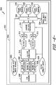
- FIG. 6 illustrates a block diagram of one embodiment of a system 300 for controlling pitching of the rotor blade(s) 22 according to the present disclosure.
- the system 300 includes the controller 302, such as controller 26, and a computer-implemented model 304 stored therein.
- position data 306 from the position localization sensors can be used by the computer-implemented model 304 to determine the pitch command(s) 318 for the rotor blade(s) 22 as a function of the blade deflection signal 308 and the azimuth angle.
- the controller 302 can derive the blade deflection 308 of each of the rotor blades 22 of the wind turbine 10.
- the controller 302 can then apply direct-quadrature (d-q) transformation 310 to the blade deflection signals 308 to transform the blade deflection signals 308 into d-q coordinates 312.
- the controller 302 may determine or derive a blade bending moment of the rotor blades 22 (e.g. M outplane1 , M outplane2 , M outplane3 ) using the respective blade deflection signals 308 and calculate the d-q coordinates 312 as a function of the blade bending moment and the azimuth angle 320.
- a linear relationship exists between the blade bending moment and the blade deflection, therefore, the blade bending moment can be derived from the blade deflection.
- the controller 302 may also filter the d-q coordinates 312 using one or more filters 314. As shown at 316, the controller 302 can then inverse the d-q transformation to transform the d-q coordinates 312 into the pitch commands 318 for the rotor blade(s) 22. In additional embodiments, as shown at 326, the controller 302 may also be configured to add a collective pitch angle demand 322 to the pitch commands 318 for the rotor blade(s) 22.
- the controller 302 may be configured to adjust the pitch commands 318 of the rotor blade(s) 22 by a pitch angle offset 324 so as to correct for pitch misalignment of the rotor blade(s) 22, as shown at 326.
- FIG. 7 a flow diagram of one embodiment of a method 400 for correcting pitch misalignment of at least one rotor blade, such as the rotor blades 22 of the wind turbine 10, is illustrated.
- the method 400 is described herein with reference to the wind turbine(s) 10, 102, and the controllers 26, 122 of FIGS. 1-3 .
- the disclosed method 400 may be implemented with wind turbines having any other suitable configurations.
- FIG. 7 depicts steps performed in a particular order for purposes of illustration and discussion, the methods discussed herein are not limited to any particular order or arrangement.
- One skilled in the art, using the disclosures provided herein, will appreciate that various steps of the methods disclosed herein can be omitted, rearranged, combined, and/or adapted in various ways without deviating from the scope of the present disclosure.
- the method 400 includes receiving, via a controller, a reference pitch angle of the rotor blade(s) 22. As shown at (404), the method 400 includes rotating the rotor blade(s) 22 to a first pitch angle.
- the reference pitch angle and the first pitch angle may be a reference pitch zero position and a first pitch zero position, respectively.
- the position data may include a zero-twist angle of the rotor blade(s) 22.
- the method 400 includes receiving and storing/recording, via one or more position localization sensors, position data relating to the rotor blade(s) 22 in the first pitch angle.
- the method 400 includes determining, via the controller, a pitch angle offset of the rotor blade(s) 22 based on a difference between the reference pitch angle and the first pitch angle. For example, as shown at (408), the method 400 includes determining a desired pitch position based on design models. As shown at (410), the method 400 includes comparing the desired pitch position from the design model with the actual pitch position from the sensors. Thus, as shown at (412), the blade pitch misalignment value can be determined by the controller. As shown at (414), the method 400 includes sending the pitch angle offset to the controller and adjusting the first pitch angle of the rotor blade(s) 22 by the pitch angle offset so as to correct the pitch misalignment.
Landscapes
- Engineering & Computer Science (AREA)
- Life Sciences & Earth Sciences (AREA)
- Sustainable Development (AREA)
- Sustainable Energy (AREA)
- Chemical & Material Sciences (AREA)
- Combustion & Propulsion (AREA)
- Mechanical Engineering (AREA)
- General Engineering & Computer Science (AREA)
- Physics & Mathematics (AREA)
- Fluid Mechanics (AREA)
- Artificial Intelligence (AREA)
- Evolutionary Computation (AREA)
- Fuzzy Systems (AREA)
- Mathematical Physics (AREA)
- Software Systems (AREA)
- Wind Motors (AREA)
Abstract
Description
- The present disclosure relates generally to wind turbines, and more specifically, to systems and methods for controlling pitch and/or pitch misalignment of a wind turbine using position data from position localization sensors, such as real-time kinematic (RTK) sensors.
- Wind power is considered one of the cleanest, most environmentally friendly energy sources presently available, and wind turbines have gained increased attention in this regard. A modern wind turbine typically includes a tower, generator, gearbox, nacelle, and one or more rotor blades. The rotor blades capture kinetic energy from wind using known foil principles and transmit the kinetic energy through rotational energy to turn a shaft coupling the rotor blades to a gearbox, or if a gearbox is not used, directly to the generator. The generator then converts the mechanical energy to electrical energy that may be deployed to a utility grid. Such configurations may also include power converters that are used to convert a frequency of generated electric power to a frequency substantially similar to a utility grid frequency.
- In modern wind turbines, various sensor systems are employed to monitor various conditions of the rotor blades. For example, such conditions may include loading and/or pitch alignment, which can have a negative impact on the annual energy production (AEP) of the wind turbine. In general, for onshore wind turbines, a plurality of proximity sensors are installed on the main shaft to measure various moments of the rotor blades. For offshore wind turbines, a plurality of strain sensors are installed on the rotor blades to measure individual blade root bending moments. More particularly, the strain signals from the strain sensors are converted into bending moments. Such sensors, however, tend to experience performance degradation and drift over time and require continued calibration.
- As to conventional methods for determining pitch alignment, there are several available methods and/or tools onshore wind turbines. For example, certain wind turbines use image processing technologies combined with the airfoil template of the rotor blades and/or lasers to correct the pitch misalignment. However, these tools/methods cannot be used in offshore wind turbines due to physical constraints (e.g. offshore wind turbines are installed on the sea with no surrounding mounting locations).
- In view of the foregoing, the art is continuously seeking new and improved systems and methods for controlling pitch and/or pitch misalignment of a wind turbine. Accordingly, the present disclosure is directed to systems and methods for controlling pitch and/or pitch misalignment of a wind turbine using position data from position localization sensors, such as real-time kinematic (RTK) sensors.
- Aspects and advantages of the invention will be set forth in part in the following description, or may be obvious from the description, or may be learned through practice of the invention.
- In one aspect, the present disclosure is directed to a method for controlling pitching of at least one rotor blade of a wind turbine. The method includes receiving, via one or more position localization sensors, position data relating to the at least one rotor blade of the wind turbine. Further, the method includes determining, via a controller, a blade deflection signal of the at least one rotor blade based on the position data. Moreover, the method includes determining, via a computer-implemented model stored in the controller, a pitch command for the at least one rotor blade as a function of the blade deflection signal and an azimuth angle of the at least one rotor blade.
- In an embodiment, the position localization sensor(s) may include one or more of the following: one or more real-time kinematic (RTK) sensors, one or more inertial navigation system (INS) sensors, one or more global positioning system (GPS) sensors, or combinations thereof.
- In particular embodiments, the position localization sensor(s) may include the RTK sensor(s). Thus, in such embodiments, the RTK sensor(s) may include a base station and a plurality of mobile stations communicatively coupled to the base station, with the plurality of mobile stations being installed on the rotor blade.
- In another embodiment, receiving the position data relating to the rotor blade of the wind turbine may include receiving, via the controller, three-dimensional or two-dimensional position data relating to a position of the base station and receiving, via the controller, three-dimensional or two-dimensional position data relating to a position of each of the plurality of mobile stations.
- In further embodiments, determining, via the computer-implemented model stored in the controller, the pitch command for the at least one rotor blade as a function of the blade deflection signal and the azimuth angle may include applying, via the controller, direct-quadrature (d-q) transformation to the blade deflection signal to transform the blade deflection signal into d-q coordinates, filtering the d-q coordinates, and inversing the d-q transformation to transform the d-q coordinates into the pitch command for the at least one rotor blade.
- In such embodiments, applying the d-q transformation to the blade deflection signal to transform the blade deflection signal into d-q coordinates may include determining a blade bending moment of the at least one rotor blade using the blade deflection and calculating the d-q coordinates as a function of the blade bending moment and the azimuth angle.
- In additional embodiments, the method may include adding a collective pitch angle demand to the pitch command for the rotor blade(s).
- In another embodiment, the wind turbine may be part of a wind farm having a plurality of wind turbines and a farm-level controller. In such embodiments, the position localization sensor(s) may communicate with the farm-level controller directly using an existing network of the wind farm or a wireless communication system.
- In still further embodiments, the method may include adjusting the pitch command of the rotor blade(s) by a pitch angle offset so as to correct for pitch misalignment of the at least one rotor blade.
- In another aspect, the present disclosure is directed to a method for correcting pitch misalignment of at least one rotor blade of a wind turbine, such as an off-shore wind turbine. The method includes receiving, via a controller, a reference pitch angle of the at least one rotor blade. Further, the method includes rotating the rotor blade(s) to a first pitch angle. Moreover, the method includes receiving, via one or more position localization sensors, position data relating to the rotor blade(s) of the wind turbine in the first pitch angle. In addition, the method includes determining, via the controller, a pitch angle offset of the rotor blade(s) based on a difference between the reference pitch angle and the first pitch angle. Thus, the method includes adjusting the first pitch angle of the rotor blade(s) by the pitch angle offset so as to correct the pitch misalignment.
- In an embodiment, the reference pitch angle and the first pitch angle may be a reference pitch zero position and a first pitch zero position, respectively. Thus, in another embodiment, the position data may include a zero-twist angle of the rotor blade(s). It should be understood that the method may further include any of the additional features and/steps as described herein.
- In one aspect, the present disclosure is directed to a system for controlling pitching of at least one rotor blade of a wind turbine. The system includes one or more position localization sensors for generating position data relating to the rotor blade(s) of the wind turbine and a controller communicatively coupled to the position localization sensor(s). The controller is configured to perform a plurality of operations, including but not limited to receiving the position data relating to the rotor blade(s) of the wind turbine, determining a blade deflection signal of the rotor blade(s) based on the position data, and determining a pitch command for the rotor blade(s) as a function of the blade deflection signal and an azimuth angle of the rotor blade(s). It should be understood that the wind farm may further include any of the additional features as described herein.
- These and other features, aspects and advantages of the present invention will become better understood with reference to the following description and appended claims. The accompanying drawings, which are incorporated in and constitute a part of this specification, illustrate embodiments of the invention and, together with the description, serve to explain the principles of the invention.
- A full and enabling disclosure of the present invention, including the best mode thereof, directed to one of ordinary skill in the art, is set forth in the specification, which makes reference to the appended figures, in which:
-
FIG. 1 illustrates a perspective view of one embodiment of a wind turbine according to the present disclosure; -
FIG. 2 illustrates a schematic view of one embodiment of a controller for use with the wind turbine shown inFIG. 1 ; -
FIG. 3 illustrates a schematic view of one embodiment of a wind farm according to the present disclosure; -
FIG. 4 illustrates a flow diagram of one embodiment of a method for controlling pitching of at least one rotor blade of a wind turbine according to the present disclosure; -
FIG. 5 illustrates a front view of one embodiment of a wind turbine according to the present disclosure, particularly illustrating a plurality of position localization sensors mounted to the rotor blades; -
FIG. 6 illustrates a block diagram of one embodiment of a system for controlling pitching of at least one rotor blade of a wind turbine according to the present disclosure; and -
FIG. 7 illustrates a flow diagram of one embodiment of a method for correcting pitch misalignment of at least one rotor blade of a wind turbine according to the present disclosure. - The figures are not necessarily drawn to scale and elements of similar structures or functions are generally represented by like reference numerals for illustrative purposes throughout the figures. The figures are only intended to facilitate the description of the various embodiments described herein. The figures do not describe every aspect of the teachings disclosed herein and do not limit the scope of the claims.
- Reference now will be made in detail to embodiments of the invention, one or more examples of which are illustrated in the drawings. Each example is provided by way of explanation of the invention, not limitation of the invention. In fact, it will be apparent to those skilled in the art that various modifications and variations can be made in the present invention without departing from the scope or spirit of the invention. For instance, features illustrated or described as part of one embodiment can be used with another embodiment to yield a still further embodiment. Thus, it is intended that the present invention covers such modifications and variations as come within the scope of the appended claims and their equivalents.
- Referring now to the drawings,
FIG. 1 illustrates a perspective view of one embodiment of awind turbine 10 configured to implement the control technology according to the present disclosure. As shown, thewind turbine 10 generally includes atower 12 extending from asupport surface 14, anacelle 16 mounted on thetower 12, and arotor 18 coupled to thenacelle 16. Therotor 18 includes arotatable hub 20 and at least onerotor blade 22 coupled to and extending outwardly from thehub 20. For example, in the illustrated embodiment, therotor 18 includes threerotor blades 22. However, in an alternative embodiment, therotor 18 may include more or less than threerotor blades 22. Eachrotor blade 22 may be spaced about thehub 20 to facilitate rotating therotor 18 to enable kinetic energy to be transferred from the wind into usable mechanical energy, and subsequently, electrical energy. - For instance, the
hub 20 may be rotatably coupled to an electric generator (not shown) positioned within thenacelle 16 to permit electrical energy to be produced. The generators are sometimes, but not always, rotationally coupled to therotor 18 through a gearbox. Thus, the gearbox is configured to step up the inherently low rotational speed of the rotor for the generator to efficiently convert the rotational mechanical energy to electric energy. Gearless direct drive wind turbines also exist. The generated electric power is transmitted to an electric grid via at least one electrical connection. Such known wind may be coupled to the electric grid via a known full power conversion assembly. More specifically, full power conversion assemblies may include a rectifier portion that converts alternating current (AC) generated by the generator to direct current (DC) and an inverter that converts the DC to AC of a predetermined frequency and voltage amplitude. - The
wind turbine 10 may also include awind turbine controller 26 centralized within thenacelle 16. However, in other embodiments, thecontroller 26 may be located within any other component of thewind turbine 10 or at a location outside the wind turbine. Further, thecontroller 26 may be communicatively coupled to any number of the components of thewind turbine 10 in order to control the operation of such components and/or to implement a control action. As such, thecontroller 26 may include a computer or other suitable processing unit. Thus, in several embodiments, thecontroller 26 may include suitable computer-readable instructions that, when implemented, configure thecontroller 26 to perform various different functions, such as receiving, transmitting and/or executing wind turbine control signals. Accordingly, thecontroller 26 may generally be configured to control the various operating modes of the wind turbine 10 (e.g., start-up or shut-down sequences), de-rate or up-rate thewind turbine 10, control various components of thewind turbine 10, and/or implement the various method steps as described herein. - For example, in certain embodiments, the methods described herein may be at least partially processor-implemented. The performance of certain of the operations may be distributed among the one or more processors, not only residing within a single machine, but deployed across a number of machines. The one or more processors may also operate to support performance of the relevant operations in a "cloud computer" environment or as a "software service" (SaaS). For example, at least some of the operations may be performed by a group of computers (as examples of machines including processors), these operations being accessible via a network (e.g., the Internet) and via one or more appropriate interfaces (e.g., Application Program Interfaces (APIs).)
- In additional embodiments, the
controller 26 may be configured to control the blade pitch or pitch angle of each of the rotor blades 22 (i.e., an angle that determines a perspective of therotor blades 22 with respect to the direction of the wind) to control the power output generated by thewind turbine 10. For instance, thecontroller 26 may control the pitch angle of therotor blades 22 by rotating therotor blades 22 about apitch axis 28, either individually or simultaneously, by transmitting suitable control signals to a pitch drive or pitch adjustment mechanism (not shown) of thewind turbine 10. - Referring now to
FIG. 2 , a block diagram of one embodiment of suitable components that may be included within the controller 26 (or farm controller 122) is illustrated in accordance with aspects of the present disclosure. The controller(s) 26, 122 may operate as a standalone device or may be coupled (e.g., networked) to other machines. In a networked deployment, thecontroller 26 may operate in the capacity of a server machine or a client machine in a server-client network environment, or as a peer machine in a peer-to-peer (or distributed) network environment. By way of non-limiting example, thecontroller 26 may include or correspond to a server computer, a client computer, a personal computer (PC), a tablet computer, a laptop computer, a netbook, a mobile device, or any machine capable of executing instructions, sequentially or otherwise, that specify actions to be taken by thecontroller 26. - As shown, the
controller 26 may include one or more processor(s) 58 and associated memory device(s) 60 (and/or input/output (I/O) components, not shown) configured to perform a variety of computer-implemented functions (e.g., performing the methods, steps, calculations and the like disclosed herein). As used herein, the term "processor" refers not only to integrated circuits referred to in the art as being included in a computer, but also refers to a controller, a microcontroller, a microcomputer, a programmable logic controller (PLC), an application specific integrated circuit, application-specific processors, digital signal processors (DSPs), Application Specific Integrated Circuits (ASICs), Field Programmable Gate Arrays (FPGAs), and/or any other programmable circuits. Further, the memory device(s) 60 may generally include memory element(s) including, but are not limited to, computer readable medium (e.g., random access memory (RAM)), computer readable nonvolatile medium (e.g., a flash memory), one or more hard disk drives, a floppy disk, a compact disc-read only memory (CD-ROM), compact disk-read/write (CD-R/W) drives, a magneto-optical disk (MOD), a digital versatile disc (DVD), flash drives, optical drives, solid-state storage devices, and/or other suitable memory elements. - Additionally, the
controller 26 may also include acommunications module 62 to facilitate communications between thecontroller 26 and the various components of thewind turbine 10. For instance, thecommunications module 62 may include a sensor interface 64 (e.g., one or more analog-to-digital converters) to permit the signals transmitted by one ormore sensors controller 26. Furthermore, it should be appreciated that thesensors communications module 62 using any suitable means. For example, as shown inFIG. 2 , thesensors sensor interface 64 via a wired connection. However, in alternative embodiments, thesensors sensor interface 64 via a wireless connection, such as by using any suitable wireless communications protocol known in the art. For example, thecommunications module 62 may include the Internet, a local area network (LAN), wireless local area networks (WLAN), wide area networks (WAN) such as Worldwide Interoperability for Microwave Access (WiMax) networks, satellite networks, cellular networks, sensor networks, ad hoc networks, and/or short-range networks. As such, theprocessor 58 may be configured to receive one or more signals from thesensors - The various components of the
controller 26, e.g. I/O components, may include a wide variety of components to receive input, provide output, produce output, transmit information, exchange information, capture measurements, and so on. The specific I/O components that are included in a particular machine will depend on the type of machine. For example, portable machines such as mobile phones will likely include a touch input device or other such input mechanisms, while a headless server machine will likely not include such a touch input device. Further, the I/O components may be grouped according to functionality merely for simplifying the following discussion and the grouping is in no way limiting. In further embodiments, the I/O components may include visual components (e.g., a display such as a plasma display panel (PDP), a light emitting diode (LED) display, a liquid crystal display (LCD), a projector, or a cathode ray tube (CRT)), acoustic components (e.g., speakers), haptic components (e.g., a vibratory motor, resistance mechanisms), other signal generators, and so forth. In additional embodiments, the I/O components may include alphanumeric input components (e.g., a keyboard, a touch screen configured to receive alphanumeric input, a photooptical keyboard, or other alphanumeric input components), point based input components (e.g., a mouse, a touchpad, a trackball, a joystick, a motion sensor, or other pointing instrument), tactile input components (e.g., a physical button, a touch screen that provides location and/or force of touches or touch gestures, or other tactile input components), audio input components (e.g., a microphone), and the like. - Referring now to
FIG. 3 , at least some wind turbines are physically positioned in a remote geographical region or in an area where physical access is difficult, such as, off-shore installations. These wind turbines may be physically nested together in a common geographical region to form a wind farm and may be electrically coupled to a common AC collector system. For example, as shown inFIG. 3 , one embodiment of awind farm 100 that may be controlled according to the present disclosure is illustrated. More specifically, as shown, thewind farm 100 may include a plurality ofwind turbines 102, including thewind turbine 10 described above, communicatively coupled to afarm controller 122 via anetwork 126. For example, as shown in the illustrated embodiment, thewind farm 100 includes twelve wind turbines, includingwind turbine 10. However, in other embodiments, thewind farm 100 may include any other number of wind turbines, such as less than twelve wind turbines or greater than twelve wind turbines. In one embodiment, thecontroller 26 of thewind turbine 10 may be communicatively coupled to thefarm controller 122 through a wired connection, such as by connecting thecontroller 26 through suitable communicative links (e.g., a suitable cable). Alternatively, thecontroller 26 may be communicatively coupled to thefarm controller 122 through a wireless connection, such as by using any suitable wireless communications protocol known in the art. In addition, thefarm controller 122 may be generally configured similar to thecontrollers 26 for each of theindividual wind turbines 102 within thewind farm 100. - In several embodiments, one or more of the
wind turbines 102 in thewind farm 100 may include a plurality of sensors for monitoring various operating data points or control settings of theindividual wind turbines 102 and/or one or more wind parameters of thewind farm 100. For example, as shown, each of thewind turbines 102 includes awind sensor 116, such as an anemometer or any other suitable device, configured for measuring wind speeds or any other wind parameter. - Accordingly, it should be understood that the
various sensors wind turbine 10 and/or wind parameters of the wind farm 100 (FIG. 3 ). For example, in an embodiment, one or more of the sensors may be a position localization sensor, such as a real-time kinematic sensor orsensor system 124, at least partially locally installed onto one or more of thewind turbines 10 and/or integrated with thewind farm controller 122, one or more global positioning system (GPS) sensors, or combinations thereof. - As used herein, position localization sensors, and more particularly real-time kinematic (RTK) sensors, generally refer to sensors that use RTK positioning, which is a satellite navigation technique used to enhance the precision of position data derived from satellite-based positioning systems (global navigation satellite systems, GNSS). Thus, RTK position systems enable a refinement in satellite positioning which is categorized in the frequency range of about 1,164-1,610 Mhz, which is a different frequency ranges from other RF-based devices (such as cellular 3G, Bluetooth, UWB, etc.) that operate at higher frequencies.
- Thus, the
sensor system 124 of the present disclosure is configured to use measurements of the phase of the signal's carrier wave in addition to the information content of the signal and relies on a single reference station or interpolated virtual station to provide real-time corrections, providing up to centimeter-level accuracy. More specifically, in certain embodiments, as shown inFIGS. 3 and4 , thesensor system 124 may use a single base-station receiver 125 and a plurality of mobile units 128 (e.g. rover station(s)). For example, as shown particularly inFIG. 4 , one or more of themobile units 128 may be locally installed onto each of therotor blades 22 of thewind turbine 10. As such, thebase station 125 re-broadcasts the phase of the carrier that it observes, and themobile units 128 compare their own phase measurements with the one received from thebase station 125. The most popular way to transmit a correction signal from thebase station 125 to one or more of themobile stations 128 to achieve real-time, low-cost signal transmission is to use a radio modem (not shown). However, in certain embodiments, as shown inFIG. 3 , rather than using the wireless RF modem, the present disclosure may also implement the communication between thebase station 125 and the rover station(s) 128 using the existingnetwork 126 of thewind farm 100. It should also be understood that the position localization sensor(s) may also include inertial navigation system (INS) sensors, global positioning system (GPS) sensors, or combinations of any sensor described herein. - In the present disclosure, for wind turbines, the measurement of positions are used as inputs to incorporate into a wind turbine model and/or algorithm to derive turbine-relevant parameters/variables (such as, model-based estimation) as described herein. Accordingly, the present disclosure encompasses a new system structure that eliminates the radio modems and additional processors of the RTK system, while also providing a more reliable and cost-effective solution. More specifically, in an embodiment, the system of the present disclosure may only need the GPS modules, with the position calculations and the subsequent estimations and controls being implemented in the existing wind turbine controllers.
- The
sensors rotor blades 22 or for measuring a loading acting on one of therotor blades 22; generator sensors for monitoring the generator (e.g. torque, rotational speed, acceleration and/or the power output); and/or various wind sensors for measuring various wind parameters (e.g. wind speed, wind direction, etc.). Further, thesensors wind turbine 10, on thenacelle 16, on a meteorological mast of thewind turbine 10, or any other location in thewind farm 100. - Accordingly, it should also be understood that any other number or type of sensors may be employed and at any location. For example, the sensors may be accelerometers, pressure sensors, strain gauges, angle of attack sensors, vibration sensors, MIMU sensors, camera systems, fiber optic systems, anemometers, wind vanes, Sonic Detection and Ranging (SODAR) sensors, infra lasers, Light Detecting and Ranging (LIDAR) sensors, radiometers, pitot tubes, rawinsondes, other optical sensors, and/or any other suitable sensors. It should be appreciated that, as used herein, the term "monitor" and variations thereof indicates that the various sensors of the
wind turbine 10 may be configured to provide a direct measurement of the parameters being monitored or an indirect measurement of such parameters. Thus, thesensors controller 26 to determine the actual condition. - Certain embodiments are described herein as including logic or a number of components, modules, or mechanisms. Modules may constitute either software modules (e.g., code embodied on a machine-readable medium or in a transmission signal) or hardware modules. A hardware module is tangible unit capable of performing certain operations and may be configured or arranged in a certain manner. In example embodiments, one or more computer systems (e.g., a standalone, client or server computer system) or one or more hardware modules of a computer system (e.g., a processor or a group of processors) may be configured by software (e.g., an application or application portion) as a hardware module that operates to perform certain operations as described herein.
- In various embodiments, a hardware module may be implemented mechanically or electronically. For example, a hardware module may include dedicated circuitry or logic that is permanently configured (e.g., as a special-purpose processor, such as a field programmable gate array (FPGA) or an application specific integrated circuit (ASIC)) to perform certain operations. A hardware module may also include programmable logic or circuitry (e.g., as encompassed within a general-purpose processor or other programmable processor) that is temporarily configured by software to perform certain operations. It will be appreciated that the decision to implement a hardware module mechanically, in dedicated and permanently configured circuitry, or in temporarily configured circuitry (e.g., configured by software) may be driven by cost and time considerations.
- Referring now to
FIG. 5 , a flow diagram of one embodiment of amethod 200 for controlling pitching of one or more rotor blades, such as the rotor blade(s) 22 of thewind turbine 10, is illustrated. In general, themethod 200 is described herein with reference to the wind turbine(s) 10, 102, and thecontrollers FIGS. 1-3 . However, it should be appreciated that the disclosedmethod 200 may be implemented with wind turbines having any other suitable configurations. In addition, althoughFIG. 5 depicts steps performed in a particular order for purposes of illustration and discussion, the methods discussed herein are not limited to any particular order or arrangement. One skilled in the art, using the disclosures provided herein, will appreciate that various steps of the methods disclosed herein can be omitted, rearranged, combined, and/or adapted in various ways without deviating from the scope of the present disclosure. - As shown at (202), the
method 200 includes receiving, via one or more position localization sensors (such as any ofsensors wind turbine 10. More specifically, in an embodiment, the position data may be three-dimensional or two-dimensional position data relating to a position of thebase station 125 and/or three-dimensional or two-dimensional position data relating to a position of each of the plurality ofmobile stations 128. - Referring still to
FIG. 5 , as shown at (204), themethod 200 includes determining, via a controller, a blade deflection signal of the rotor blade(s) 22 based on the position data. As shown at (206), themethod 200 includes determining, via a computer-implemented model stored in the controller, a pitch command for the rotor blade(s) 22 as a function of the blade deflection signal and an azimuth angle of the rotor blade(s) 22. - The
method 200 ofFIG. 5 can be better understood with reference toFIG. 6 . For example,FIG. 6 illustrates a block diagram of one embodiment of asystem 300 for controlling pitching of the rotor blade(s) 22 according to the present disclosure. Thus, as shown, thesystem 300 includes thecontroller 302, such ascontroller 26, and a computer-implementedmodel 304 stored therein. Accordingly, as shown,position data 306 from the position localization sensors can be used by the computer-implementedmodel 304 to determine the pitch command(s) 318 for the rotor blade(s) 22 as a function of theblade deflection signal 308 and the azimuth angle. More specifically, as shown, thecontroller 302 can derive theblade deflection 308 of each of therotor blades 22 of thewind turbine 10. - Moreover, the
controller 302 can then apply direct-quadrature (d-q)transformation 310 to the blade deflection signals 308 to transform the blade deflection signals 308 into d-q coordinates 312. In such embodiments, for example, thecontroller 302 may determine or derive a blade bending moment of the rotor blades 22 (e.g. Moutplane1, Moutplane2, Moutplane3) using the respective blade deflection signals 308 and calculate the d-q coordinates 312 as a function of the blade bending moment and theazimuth angle 320. Generally, a linear relationship exists between the blade bending moment and the blade deflection, therefore, the blade bending moment can be derived from the blade deflection. Accordingly, in one embodiment, the d-q coordinates 312 may be derived from Equations (1) and (2) below:

- Still referring to
FIG. 6 , as shown, thecontroller 302 may also filter the d-q coordinates 312 using one ormore filters 314. As shown at 316, thecontroller 302 can then inverse the d-q transformation to transform the d-q coordinates 312 into the pitch commands 318 for the rotor blade(s) 22. In additional embodiments, as shown at 326, thecontroller 302 may also be configured to add a collectivepitch angle demand 322 to the pitch commands 318 for the rotor blade(s) 22. Moreover, in an embodiment, thecontroller 302 may be configured to adjust the pitch commands 318 of the rotor blade(s) 22 by a pitch angle offset 324 so as to correct for pitch misalignment of the rotor blade(s) 22, as shown at 326. - Referring now to
FIG. 7 , a flow diagram of one embodiment of amethod 400 for correcting pitch misalignment of at least one rotor blade, such as therotor blades 22 of thewind turbine 10, is illustrated. In general, themethod 400 is described herein with reference to the wind turbine(s) 10, 102, and thecontrollers FIGS. 1-3 . However, it should be appreciated that the disclosedmethod 400 may be implemented with wind turbines having any other suitable configurations. In addition, althoughFIG. 7 depicts steps performed in a particular order for purposes of illustration and discussion, the methods discussed herein are not limited to any particular order or arrangement. One skilled in the art, using the disclosures provided herein, will appreciate that various steps of the methods disclosed herein can be omitted, rearranged, combined, and/or adapted in various ways without deviating from the scope of the present disclosure. - As shown at (402), the
method 400 includes receiving, via a controller, a reference pitch angle of the rotor blade(s) 22. As shown at (404), themethod 400 includes rotating the rotor blade(s) 22 to a first pitch angle. For example, in an embodiment, the reference pitch angle and the first pitch angle may be a reference pitch zero position and a first pitch zero position, respectively. In another embodiment, the position data may include a zero-twist angle of the rotor blade(s) 22. As shown at (406), themethod 400 includes receiving and storing/recording, via one or more position localization sensors, position data relating to the rotor blade(s) 22 in the first pitch angle. As shown at (408) through (412), themethod 400 includes determining, via the controller, a pitch angle offset of the rotor blade(s) 22 based on a difference between the reference pitch angle and the first pitch angle. For example, as shown at (408), themethod 400 includes determining a desired pitch position based on design models. As shown at (410), themethod 400 includes comparing the desired pitch position from the design model with the actual pitch position from the sensors. Thus, as shown at (412), the blade pitch misalignment value can be determined by the controller. As shown at (414), themethod 400 includes sending the pitch angle offset to the controller and adjusting the first pitch angle of the rotor blade(s) 22 by the pitch angle offset so as to correct the pitch misalignment. - Although the embodiments of the present invention have been described with reference to specific example embodiments, it will be evident that various modifications and changes may be made to these embodiments without departing from the broader scope of the inventive subject matter. Accordingly, the specification and drawings are to be regarded in an illustrative rather than a restrictive sense. The accompanying drawings that form a part hereof show by way of illustration, and not of limitation, specific embodiments in which the subject matter may be practiced. The embodiments illustrated are described in sufficient detail to enable those skilled in the art to practice the teachings disclosed herein. Other embodiments may be used and derived therefrom, such that structural and logical substitutions and changes may be made without departing from the scope of this disclosure.
- Various aspects and embodiments of the present invention are defined by the following numbered clauses:
-
Clause 1. A method for controlling pitching of at least one rotor blade of a wind turbine, the method comprising:- receiving, via one or more position localization sensors, position data relating to the at least one rotor blade of the wind turbine;
- determining, via a controller, a blade deflection signal of the at least one rotor blade based on the position data; and,
- determining, via a computer-implemented model stored in the controller, a pitch command for the at least one rotor blade as a function of the blade deflection signal and an azimuth angle of the at least one rotor blade.
-
Clause 2. The method ofclause 1, wherein the one or more position localization sensors comprise one or more of the following: one or more real-time kinematic (RTK) sensors, one or more inertial navigation system (INS) sensors, one or more global positioning system (GPS) sensors, or combinations thereof. -
Clause 3. The method ofclause 2, wherein the one or more position localization sensors comprise the one or more RTK sensors. - Clause 4. The method of
clause 3, wherein the one or more RTK sensors comprise a base station and a plurality of mobile stations communicatively coupled to the base station, the plurality of mobile stations being installed on the rotor blade. - Clause 5. The method of any of the preceding clauses, wherein receiving the position data relating to the rotor blade of the wind turbine further comprises:
- receiving, via the controller, three-dimensional or two-dimensional position data relating to a position of the base station; and,
- receiving, via the controller, three-dimensional or two-dimensional position data relating to a position of each of the plurality of mobile stations.
- Clause 6. The method of any of the preceding claims, wherein determining, via the computer-implemented model stored in the controller, the pitch command for the at least one rotor blade as a function of the blade deflection signal and the azimuth angle further comprises:
- applying, via the controller, direct-quadrature (d-q) transformation to the blade deflection signal to transform the blade deflection signal into d-q coordinates;
- filtering the d-q coordinates; and,
- inversing the d-q transformation to transform the filtered d-q coordinates into the pitch command for the at least one rotor blade.
- Clause 7. The method of any of the preceding claims, wherein applying the d-q transformation to the blade deflection signal to transform the blade deflection signal into d-q coordinates further comprises:
- determining a blade bending moment of the at least one rotor blade using the blade deflection; and,
- calculating the d-q coordinates as a function of the blade bending moment and the azimuth angle.
- Clause 8. The method of any of the preceding claims, further comprising adding a collective pitch angle demand to the pitch command for the at least one rotor blade.
- Clause 9. The method of any of the preceding claims, wherein the wind turbine is part of a wind farm comprising a plurality of wind turbines and a farm-level controller, the one or more position localization sensors communicating with the farm-level controller directly using an existing network of the wind farm or a wireless communication system.
-
Clause 10. The method of any of the preceding claims, further comprising adjusting the pitch command of the at least one rotor blade by a pitch angle offset so as to correct for pitch misalignment of the at least one rotor blade. - Clause 11. A method for correcting pitch misalignment of at least one rotor blade of a wind turbine, the method comprising:
- receiving, via a controller, a reference pitch angle of the at least one rotor blade;
- rotating the at least one rotor blade to a first pitch angle;
- receiving, via one or more position localization sensors, position data relating to the at least one rotor blade of the wind turbine in the first pitch angle;
- determining, via the controller, a pitch angle offset of the at least one rotor blade based on a difference between the reference pitch angle and the first pitch angle; and,
- adjusting the first pitch angle of the at least one rotor blade by the pitch angle offset so as to correct the pitch misalignment.
-
Clause 12. The method of clause 11, wherein the reference pitch angle and the first pitch angle comprise a reference pitch zero position and a first pitch zero position, respectively. - Clause 13. The method of any of clauses 11-12, wherein the position data comprises a zero-twist angle of the at least one rotor blade.
-
Clause 14. The method of any of clauses 11-13, wherein the one or more position localization sensors comprise one or more of the following: one or more real-time kinematic (RTK) sensors, one or more inertial navigation system (INS) sensors, one or more global positioning system (GPS) sensors, or combinations thereof. - Clause 15. The method of any of
clause 14, wherein the one or more position localization sensors comprise the one or more RTK sensors, the one or more RTK sensors comprising a base station and a plurality of mobile stations communicatively coupled to the base station, the plurality of mobile stations being installed on the rotor blade. -
Clause 16. The method of any of clauses 11-15, wherein the wind turbine comprises an off-shore wind turbine. - Clause 17. A system for controlling pitching of at least one rotor blade of a wind turbine, the system comprising:
- one or more position localization sensors for generating position data relating to the at least one rotor blade of the wind turbine;
- a controller communicatively coupled to the one or more position localization sensors, the controller configured to perform a plurality of operations, the plurality of operations comprising:
- receiving the position data relating to the at least one rotor blade of the wind turbine;
- determining a blade deflection signal of the at least one rotor blade based on the position data; and,
- determining a pitch command for the at least one rotor blade as a function of the blade deflection signal and an azimuth angle of the at least one rotor blade.
-
Clause 18. The system of clause 17, wherein the one or more position localization sensors comprise one or more of the following: one or more real-time kinematic (RTK) sensors, one or more inertial navigation system (INS) sensors, one or more global positioning system (GPS) sensors, or combinations thereof. - Clause 19. The system of clauses 17-18, wherein the one or more position localization sensors comprise the one or more RTK sensors, the one or more RTK sensors comprising a base station and a plurality of mobile stations communicatively coupled to the base station, the plurality of mobile stations being installed on the rotor blade.
-
Clause 20. The system of clause 19, wherein receiving the position data relating to the rotor blade of the wind turbine further comprises:- receiving three-dimensional or two-dimensional position data relating to a position of the base station; and,
- receiving three-dimensional or two-dimensional position data relating to a position of each of the plurality of mobile stations.
- This written description uses examples to disclose the invention, including the best mode, and also to enable any person skilled in the art to practice the invention, including making and using any devices or systems and performing any incorporated methods. The patentable scope of the invention is defined by the claims, and may include other examples that occur to those skilled in the art. Such other examples are intended to be within the scope of the claims if they include structural elements that do not differ from the literal language of the claims, or if they include equivalent structural elements with insubstantial differences from the literal languages of the claims.
Claims (15)
- A method for controlling pitching of at least one rotor blade of a wind turbine, the method comprising:receiving, via one or more position localization sensors, position data relating to the at least one rotor blade of the wind turbine;determining, via a controller, a blade deflection signal of the at least one rotor blade based on the position data; and,determining, via a computer-implemented model stored in the controller, a pitch command for the at least one rotor blade as a function of the blade deflection signal and an azimuth angle of the at least one rotor blade.
- The method of claim 1, wherein the one or more position localization sensors comprise one or more of the following: one or more real-time kinematic (RTK) sensors, one or more inertial navigation system (INS) sensors, one or more global positioning system (GPS) sensors, or combinations thereof.
- The method of claim 2, wherein the one or more position localization sensors comprise the one or more RTK sensors.
- The method of claim 3, wherein the one or more RTK sensors comprise a base station and a plurality of mobile stations communicatively coupled to the base station, the plurality of mobile stations being installed on the rotor blade.
- The method of claim 4, wherein receiving the position data relating to the rotor blade of the wind turbine further comprises:receiving, via the controller, three-dimensional or two-dimensional position data relating to a position of the base station; and,receiving, via the controller, three-dimensional or two-dimensional position data relating to a position of each of the plurality of mobile stations.
- The method of any of the preceding claims, wherein determining, via the computer-implemented model stored in the controller, the pitch command for the at least one rotor blade as a function of the blade deflection signal and the azimuth angle further comprises:applying, via the controller, direct-quadrature (d-q) transformation to the blade deflection signal to transform the blade deflection signal into d-q coordinates;filtering the d-q coordinates; and,inversing the d-q transformation to transform the filtered d-q coordinates into the pitch command for the at least one rotor blade.
- The method of any of the preceding claims, wherein applying the d-q transformation to the blade deflection signal to transform the blade deflection signal into d-q coordinates further comprises:determining a blade bending moment of the at least one rotor blade using the blade deflection; and,calculating the d-q coordinates as a function of the blade bending moment and the azimuth angle.
- The method of any of the preceding claims, further comprising adding a collective pitch angle demand to the pitch command for the at least one rotor blade.
- The method of any of the preceding claims, wherein the wind turbine is part of a wind farm comprising a plurality of wind turbines and a farm-level controller, the one or more position localization sensors communicating with the farm-level controller directly using an existing network of the wind farm or a wireless communication system.
- The method of any of the preceding claims, further comprising adjusting the pitch command of the at least one rotor blade by a pitch angle offset so as to correct for pitch misalignment of the at least one rotor blade.
- A method for correcting pitch misalignment of at least one rotor blade of a wind turbine, the method comprising:receiving, via a controller, a reference pitch angle of the at least one rotor blade;rotating the at least one rotor blade to a first pitch angle;receiving, via one or more position localization sensors, position data relating to the at least one rotor blade of the wind turbine in the first pitch angle;determining, via the controller, a pitch angle offset of the at least one rotor blade based on a difference between the reference pitch angle and the first pitch angle; and,adjusting the first pitch angle of the at least one rotor blade by the pitch angle offset so as to correct the pitch misalignment.
- The method of claim 11, wherein the reference pitch angle and the first pitch angle comprise a reference pitch zero position and a first pitch zero position, respectivel y.
- The method of claims 11-12, wherein the position data comprises a zero-twist angle of the at least one rotor blade.
- The method of claims 11-13, wherein the one or more position localization sensors comprise one or more of the following: one or more real-time kinematic (RTK) sensors, one or more inertial navigation system (INS) sensors, one or more global positioning system (GPS) sensors, or combinations thereof.
- The method of claim 14, wherein the one or more position localization sensors comprise the one or more RTK sensors, the one or more RTK sensors comprising a base station and a plurality of mobile stations communicatively coupled to the base station, the plurality of mobile stations being installed on the rotor blade.
Applications Claiming Priority (1)
| Application Number | Priority Date | Filing Date | Title |
|---|---|---|---|
| US16/783,236 US11698052B2 (en) | 2020-02-06 | 2020-02-06 | Pitch control of a wind turbine based position data from position localization sensors |
Publications (2)
| Publication Number | Publication Date |
|---|---|
| EP3862558A1 true EP3862558A1 (en) | 2021-08-11 |
| EP3862558B1 EP3862558B1 (en) | 2024-11-27 |
Family
ID=74556794
Family Applications (1)
| Application Number | Title | Priority Date | Filing Date |
|---|---|---|---|
| EP21155551.1A Active EP3862558B1 (en) | 2020-02-06 | 2021-02-05 | Pitch control of a wind turbine based position data from position localization sensors |
Country Status (6)
| Country | Link |
|---|---|
| US (1) | US11698052B2 (en) |
| EP (1) | EP3862558B1 (en) |
| CN (1) | CN113217278B (en) |
| CA (1) | CA3107286A1 (en) |
| DK (1) | DK3862558T3 (en) |
| ES (1) | ES3008083T3 (en) |
Families Citing this family (9)
| Publication number | Priority date | Publication date | Assignee | Title |
|---|---|---|---|---|
| CN110632346B (en) * | 2018-11-29 | 2022-08-26 | 北京金风科创风电设备有限公司 | Method, device and system for correcting installation error of wind vane |
| WO2020239178A1 (en) * | 2019-05-28 | 2020-12-03 | Vestas Wind Systems A/S | Reduction of edgewise vibrations using torsional vibration signal |
| US12331722B2 (en) * | 2020-05-04 | 2025-06-17 | Vestas Wind Systems A/S | Blade monitoring by actively promoting blade vibrations |
| CN115773209B (en) * | 2021-09-06 | 2025-07-22 | 北京瓦特曼智能科技有限公司 | Fan blade clearance detection device and detection method |
| US12066010B2 (en) | 2022-04-04 | 2024-08-20 | Ge Infrastructure Technology Llc | Method and system for determining and tracking wind turbine tower deflection |
| CN115342027B (en) * | 2022-08-26 | 2023-06-16 | 中国长江三峡集团有限公司 | Variable pitch control system of wind power generation equipment |
| EP4339452A1 (en) * | 2022-09-19 | 2024-03-20 | Nordex Energy SE & Co. KG | Method for operating a wind turbine, control system and wind turbine |
| US12529354B2 (en) * | 2022-10-21 | 2026-01-20 | Vestas Wind Systems A/S | Wind turbine rotor blade pitch control for tower fatigue reduction |
| CN121497550B (en) * | 2026-01-14 | 2026-04-03 | 华电电力科学研究院有限公司 | Active wake yaw regulation and control method and device considering fatigue damage of wind turbine generator |
Citations (5)
| Publication number | Priority date | Publication date | Assignee | Title |
|---|---|---|---|---|
| US20040057828A1 (en) * | 2002-09-23 | 2004-03-25 | Bosche John Vanden | Wind turbine blade deflection control system |
| US20110144815A1 (en) * | 2010-06-30 | 2011-06-16 | General Electric Company | System for detecting proximity between a wind turbine blade and a tower wall |
| US20130287567A1 (en) * | 2010-11-02 | 2013-10-31 | Vestas Wind Systems A/S | System and method for identifying the likelihood of a tower strike where a rotor blade strikes the tower of a wind turbine |
| WO2018107298A1 (en) * | 2016-12-16 | 2018-06-21 | Cartier Energie Eolienne Inc. | System and method for monitoring blade deflection of wind turbines |
| WO2019110624A1 (en) * | 2017-12-04 | 2019-06-13 | Nidec Ssb Wind Systems Gmbh | Wind-turbine tower to blade-tip measuring system |
Family Cites Families (21)
| Publication number | Priority date | Publication date | Assignee | Title |
|---|---|---|---|---|
| ES2238936B1 (en) | 2004-02-27 | 2006-11-16 | INSTITUTO NACIONAL DE TECNICA AEROESPACIAL "ESTEBAN TERRADAS" | SYSTEM AND METHOD OF FUSION OF SENSORS TO ESTIMATE POSITION, SPEED AND ORIENTATION OF A VEHICLE, ESPECIALLY AN AIRCRAFT. |
| US7317260B2 (en) * | 2004-05-11 | 2008-01-08 | Clipper Windpower Technology, Inc. | Wind flow estimation and tracking using tower dynamics |
| US8736092B2 (en) * | 2008-03-07 | 2014-05-27 | Vestas Wind Systems A/S | Control system and a method for redundant control of a wind turbine |
| EP2324259A2 (en) * | 2008-08-13 | 2011-05-25 | Vestas Wind Systems A/S | Wind turbine rotor and method of calibrating rotor blade pitch |
| US20110229300A1 (en) * | 2010-03-16 | 2011-09-22 | Stichting Energieonderzoek Centrum Nederland | Apparatus and method for individual pitch control in wind turbines |
| GB201121590D0 (en) * | 2011-12-15 | 2012-01-25 | Lm Wind Power As | A wind turbine blade control method |
| US20130193686A1 (en) * | 2012-01-27 | 2013-08-01 | General Electric Company | System and methods for determining pitch angles for a wind turbine during peak shaving |
| ES2422562B1 (en) * | 2012-03-08 | 2014-09-30 | Gamesa Innovation & Technology S.L. | Methods and systems to relieve loads in marine wind turbines |
| CN105089931A (en) | 2014-05-13 | 2015-11-25 | 通用电气公司 | Draught fan and alignment method for draught fan blades |
| DE102015221092A1 (en) * | 2015-10-28 | 2017-05-04 | Robert Bosch Gmbh | Method and information system for detecting at least one plant parameter data set of a plant growing on a field |
| US11022100B2 (en) * | 2015-12-17 | 2021-06-01 | General Electric Company | System and method for controlling wind turbines |
| DE102015122126A1 (en) | 2015-12-17 | 2017-06-22 | Wobben Properties Gmbh | Method for determining an azimuth angle of a wind energy plant |
| DE102016117191A1 (en) * | 2016-09-13 | 2018-03-15 | fos4X GmbH | Method and device for determining loads on a tower of a wind energy plant |
| CN206158920U (en) * | 2016-09-27 | 2017-05-10 | 上海致远绿色能源股份有限公司 | Permanent magnet wind turbine self -power becomes oar system |
| CN110520620B (en) * | 2017-02-22 | 2022-09-20 | 西门子歌美飒可再生能源公司 | Method for reducing loads on a wind turbine blade pitch bearing |
| DE102017205647A1 (en) * | 2017-03-14 | 2018-09-20 | Bitmanagement Software GmbH | METHOD FOR DETERMINING A PATH ALONG AN OBJECT, SYSTEM AND METHOD FOR AUTOMATIC INSPECTION OF AN OBJECT |
| US10781792B2 (en) * | 2017-05-18 | 2020-09-22 | General Electric Company | System and method for controlling a pitch angle of a wind turbine rotor blade |
| ES2953633T3 (en) * | 2018-05-09 | 2023-11-14 | Vestas Wind Sys As | Rotor control system to reduce structural vibrations of a wind turbine |
| US11572865B2 (en) * | 2018-07-11 | 2023-02-07 | Vestas Wind Systems A/S | Method and system for controlling a wind turbine to reduce nacelle vibration |
| DE102019112976A1 (en) * | 2019-05-16 | 2020-11-19 | Wobben Properties Gmbh | Method for determining a rotor alignment of a rotor in a wind turbine |
| WO2020239177A1 (en) * | 2019-05-28 | 2020-12-03 | Vestas Wind Systems A/S | Reduction of edgewise vibrations using blade load signal |
-
2020
- 2020-02-06 US US16/783,236 patent/US11698052B2/en active Active
-
2021
- 2021-01-27 CA CA3107286A patent/CA3107286A1/en active Pending
- 2021-02-05 ES ES21155551T patent/ES3008083T3/en active Active
- 2021-02-05 CN CN202110159612.5A patent/CN113217278B/en active Active
- 2021-02-05 EP EP21155551.1A patent/EP3862558B1/en active Active
- 2021-02-05 DK DK21155551.1T patent/DK3862558T3/en active
Patent Citations (5)
| Publication number | Priority date | Publication date | Assignee | Title |
|---|---|---|---|---|
| US20040057828A1 (en) * | 2002-09-23 | 2004-03-25 | Bosche John Vanden | Wind turbine blade deflection control system |
| US20110144815A1 (en) * | 2010-06-30 | 2011-06-16 | General Electric Company | System for detecting proximity between a wind turbine blade and a tower wall |
| US20130287567A1 (en) * | 2010-11-02 | 2013-10-31 | Vestas Wind Systems A/S | System and method for identifying the likelihood of a tower strike where a rotor blade strikes the tower of a wind turbine |
| WO2018107298A1 (en) * | 2016-12-16 | 2018-06-21 | Cartier Energie Eolienne Inc. | System and method for monitoring blade deflection of wind turbines |
| WO2019110624A1 (en) * | 2017-12-04 | 2019-06-13 | Nidec Ssb Wind Systems Gmbh | Wind-turbine tower to blade-tip measuring system |
Non-Patent Citations (1)
| Title |
|---|
| TORDAL SONDRE SANDEN ET AL: "Inverse kinematic control of an industrial robot used in Vessel-to-Vessel Motion Compensation", 2017 25TH MEDITERRANEAN CONFERENCE ON CONTROL AND AUTOMATION (MED), IEEE, 3 July 2017 (2017-07-03), pages 1392 - 1397, XP033125250, DOI: 10.1109/MED.2017.7984313 * |
Also Published As
| Publication number | Publication date |
|---|---|
| US20210246871A1 (en) | 2021-08-12 |
| DK3862558T3 (en) | 2025-02-17 |
| EP3862558B1 (en) | 2024-11-27 |
| ES3008083T3 (en) | 2025-03-21 |
| CN113217278A (en) | 2021-08-06 |
| US11698052B2 (en) | 2023-07-11 |
| BR102021002175A2 (en) | 2021-10-13 |
| CN113217278B (en) | 2025-12-05 |
| CA3107286A1 (en) | 2021-08-06 |
Similar Documents
| Publication | Publication Date | Title |
|---|---|---|
| EP3862558B1 (en) | Pitch control of a wind turbine based position data from position localization sensors | |
| EP3862562A1 (en) | System and method for optimizing wake management in wind farms | |
| EP3464895B1 (en) | System and method for forecasting power output of a wind farm | |
| EP3276164B1 (en) | System and method for controlling a wind turbine | |
| US9606518B2 (en) | Control system and method of predicting wind turbine power generation | |
| CN101568721B (en) | Wind power generation device, wind power generation system, and power generation control method for wind power generation device | |
| US10774810B2 (en) | System and method for estimating high bandwidth tower deflection for wind turbines | |
| US8292579B2 (en) | Method and system for deicing wind turbine rotor blades with induced torque | |
| US10767633B2 (en) | Method and system for determining the dynamic twist of a wind turbine blade | |
| EP2762721B2 (en) | Method and apparatus for wind turbine noise reduction | |
| CN108843497B (en) | Yaw control method and equipment of wind generating set | |
| EP2469083A2 (en) | Offshore wind turbine and method of operating same | |
| EP2910777B1 (en) | Dynamic cut-in wind speed for wind turbines | |
| US20210115897A1 (en) | System and method for controlling a wind turbine based on a collective pitch-offset | |
| US20130094961A1 (en) | Estimation of wind properties using a light detection and ranging device | |
| JP2017506311A (en) | Method and system for improving energy capture efficiency of an energy capture device | |
| EP2607689A2 (en) | Rotor-sector based control of wind turbines | |
| CN114846237A (en) | Device for determining the distance between a wind turbine blade and its wind turbine tower when passing | |
| JP6609462B2 (en) | Wind power generation system | |
| US9759189B2 (en) | Wind power plant and method of controlling wind turbine generator in a wind power plant | |
| CN113252938B (en) | Method for determining wind speed in the rotor plane of a wind turbine | |
| WO2013000475A1 (en) | Remote sensing system for wind turbines | |
| US20220106937A1 (en) | METHOD OF DETERMINING AVERAGE WIND SPEED BY MEANS OF A LiDAR SENSOR | |
| BR102021002175B1 (en) | METHOD FOR CONTROLLING THE PITCH OF AT LEAST ONE ROTOR BLADE OF A WIND TURBINE | |
| KR102134008B1 (en) | Apparatus and method for motion detection in wind power generator |
Legal Events
| Date | Code | Title | Description |
|---|---|---|---|
| PUAI | Public reference made under article 153(3) epc to a published international application that has entered the european phase |
Free format text: ORIGINAL CODE: 0009012 |
|
| STAA | Information on the status of an ep patent application or granted ep patent |
Free format text: STATUS: THE APPLICATION HAS BEEN PUBLISHED |
|
| AK | Designated contracting states |
Kind code of ref document: A1 Designated state(s): AL AT BE BG CH CY CZ DE DK EE ES FI FR GB GR HR HU IE IS IT LI LT LU LV MC MK MT NL NO PL PT RO RS SE SI SK SM TR |
|
| STAA | Information on the status of an ep patent application or granted ep patent |
Free format text: STATUS: REQUEST FOR EXAMINATION WAS MADE |
|
| 17P | Request for examination filed |
Effective date: 20220208 |
|
| RBV | Designated contracting states (corrected) |
Designated state(s): AL AT BE BG CH CY CZ DE DK EE ES FI FR GB GR HR HU IE IS IT LI LT LU LV MC MK MT NL NO PL PT RO RS SE SI SK SM TR |
|
| P01 | Opt-out of the competence of the unified patent court (upc) registered |
Effective date: 20230530 |
|
| RAP1 | Party data changed (applicant data changed or rights of an application transferred) |
Owner name: GENERAL ELECTRIC RENOVABLES ESPANA, S.L. |
|
| STAA | Information on the status of an ep patent application or granted ep patent |
Free format text: STATUS: EXAMINATION IS IN PROGRESS |
|
| 17Q | First examination report despatched |
Effective date: 20240215 |
|
| GRAP | Despatch of communication of intention to grant a patent |
Free format text: ORIGINAL CODE: EPIDOSNIGR1 |
|
| STAA | Information on the status of an ep patent application or granted ep patent |
Free format text: STATUS: GRANT OF PATENT IS INTENDED |
|
| INTG | Intention to grant announced |
Effective date: 20240712 |
|
| GRAS | Grant fee paid |
Free format text: ORIGINAL CODE: EPIDOSNIGR3 |
|
| GRAA | (expected) grant |
Free format text: ORIGINAL CODE: 0009210 |
|
| STAA | Information on the status of an ep patent application or granted ep patent |
Free format text: STATUS: THE PATENT HAS BEEN GRANTED |
|
| RIN1 | Information on inventor provided before grant (corrected) |
Inventor name: LANDA, BERNARD P. Inventor name: FU, XU |
|
| AK | Designated contracting states |
Kind code of ref document: B1 Designated state(s): AL AT BE BG CH CY CZ DE DK EE ES FI FR GB GR HR HU IE IS IT LI LT LU LV MC MK MT NL NO PL PT RO RS SE SI SK SM TR |
|
| REG | Reference to a national code |
Ref country code: GB Ref legal event code: FG4D |
|
| REG | Reference to a national code |
Ref country code: CH Ref legal event code: EP |
|
| REG | Reference to a national code |
Ref country code: IE Ref legal event code: FG4D |
|
| REG | Reference to a national code |
Ref country code: DE Ref legal event code: R096 Ref document number: 602021022263 Country of ref document: DE |
|
| REG | Reference to a national code |
Ref country code: DK Ref legal event code: T3 Effective date: 20250212 |
|
| REG | Reference to a national code |
Ref country code: ES Ref legal event code: FG2A Ref document number: 3008083 Country of ref document: ES Kind code of ref document: T3 Effective date: 20250321 |
|
| REG | Reference to a national code |
Ref country code: LT Ref legal event code: MG9D |
|
| REG | Reference to a national code |
Ref country code: NL Ref legal event code: MP Effective date: 20241127 |
|
| PG25 | Lapsed in a contracting state [announced via postgrant information from national office to epo] |
Ref country code: IS Free format text: LAPSE BECAUSE OF FAILURE TO SUBMIT A TRANSLATION OF THE DESCRIPTION OR TO PAY THE FEE WITHIN THE PRESCRIBED TIME-LIMIT Effective date: 20250327 Ref country code: PT Free format text: LAPSE BECAUSE OF FAILURE TO SUBMIT A TRANSLATION OF THE DESCRIPTION OR TO PAY THE FEE WITHIN THE PRESCRIBED TIME-LIMIT Effective date: 20250327 Ref country code: HR Free format text: LAPSE BECAUSE OF FAILURE TO SUBMIT A TRANSLATION OF THE DESCRIPTION OR TO PAY THE FEE WITHIN THE PRESCRIBED TIME-LIMIT Effective date: 20241127 |
|
| PG25 | Lapsed in a contracting state [announced via postgrant information from national office to epo] |
Ref country code: FI Free format text: LAPSE BECAUSE OF FAILURE TO SUBMIT A TRANSLATION OF THE DESCRIPTION OR TO PAY THE FEE WITHIN THE PRESCRIBED TIME-LIMIT Effective date: 20241127 Ref country code: NL Free format text: LAPSE BECAUSE OF FAILURE TO SUBMIT A TRANSLATION OF THE DESCRIPTION OR TO PAY THE FEE WITHIN THE PRESCRIBED TIME-LIMIT Effective date: 20241127 |
|
| REG | Reference to a national code |
Ref country code: AT Ref legal event code: MK05 Ref document number: 1745943 Country of ref document: AT Kind code of ref document: T Effective date: 20241127 |
|
| PG25 | Lapsed in a contracting state [announced via postgrant information from national office to epo] |
Ref country code: BG Free format text: LAPSE BECAUSE OF FAILURE TO SUBMIT A TRANSLATION OF THE DESCRIPTION OR TO PAY THE FEE WITHIN THE PRESCRIBED TIME-LIMIT Effective date: 20241127 |
|
| PG25 | Lapsed in a contracting state [announced via postgrant information from national office to epo] |
Ref country code: NO Free format text: LAPSE BECAUSE OF FAILURE TO SUBMIT A TRANSLATION OF THE DESCRIPTION OR TO PAY THE FEE WITHIN THE PRESCRIBED TIME-LIMIT Effective date: 20250227 |
|
| PG25 | Lapsed in a contracting state [announced via postgrant information from national office to epo] |
Ref country code: LV Free format text: LAPSE BECAUSE OF FAILURE TO SUBMIT A TRANSLATION OF THE DESCRIPTION OR TO PAY THE FEE WITHIN THE PRESCRIBED TIME-LIMIT Effective date: 20241127 Ref country code: GR Free format text: LAPSE BECAUSE OF FAILURE TO SUBMIT A TRANSLATION OF THE DESCRIPTION OR TO PAY THE FEE WITHIN THE PRESCRIBED TIME-LIMIT Effective date: 20250228 Ref country code: AT Free format text: LAPSE BECAUSE OF FAILURE TO SUBMIT A TRANSLATION OF THE DESCRIPTION OR TO PAY THE FEE WITHIN THE PRESCRIBED TIME-LIMIT Effective date: 20241127 |
|
| PG25 | Lapsed in a contracting state [announced via postgrant information from national office to epo] |
Ref country code: PL Free format text: LAPSE BECAUSE OF FAILURE TO SUBMIT A TRANSLATION OF THE DESCRIPTION OR TO PAY THE FEE WITHIN THE PRESCRIBED TIME-LIMIT Effective date: 20241127 |
|
| PG25 | Lapsed in a contracting state [announced via postgrant information from national office to epo] |
Ref country code: RS Free format text: LAPSE BECAUSE OF FAILURE TO SUBMIT A TRANSLATION OF THE DESCRIPTION OR TO PAY THE FEE WITHIN THE PRESCRIBED TIME-LIMIT Effective date: 20250227 |
|
| PG25 | Lapsed in a contracting state [announced via postgrant information from national office to epo] |
Ref country code: SM Free format text: LAPSE BECAUSE OF FAILURE TO SUBMIT A TRANSLATION OF THE DESCRIPTION OR TO PAY THE FEE WITHIN THE PRESCRIBED TIME-LIMIT Effective date: 20241127 |
|
| PG25 | Lapsed in a contracting state [announced via postgrant information from national office to epo] |
Ref country code: EE Free format text: LAPSE BECAUSE OF FAILURE TO SUBMIT A TRANSLATION OF THE DESCRIPTION OR TO PAY THE FEE WITHIN THE PRESCRIBED TIME-LIMIT Effective date: 20241127 |
|
| PG25 | Lapsed in a contracting state [announced via postgrant information from national office to epo] |
Ref country code: RO Free format text: LAPSE BECAUSE OF FAILURE TO SUBMIT A TRANSLATION OF THE DESCRIPTION OR TO PAY THE FEE WITHIN THE PRESCRIBED TIME-LIMIT Effective date: 20241127 |
|
| PG25 | Lapsed in a contracting state [announced via postgrant information from national office to epo] |
Ref country code: SK Free format text: LAPSE BECAUSE OF FAILURE TO SUBMIT A TRANSLATION OF THE DESCRIPTION OR TO PAY THE FEE WITHIN THE PRESCRIBED TIME-LIMIT Effective date: 20241127 |
|
| PG25 | Lapsed in a contracting state [announced via postgrant information from national office to epo] |
Ref country code: CZ Free format text: LAPSE BECAUSE OF FAILURE TO SUBMIT A TRANSLATION OF THE DESCRIPTION OR TO PAY THE FEE WITHIN THE PRESCRIBED TIME-LIMIT Effective date: 20241127 |
|
| PG25 | Lapsed in a contracting state [announced via postgrant information from national office to epo] |
Ref country code: IT Free format text: LAPSE BECAUSE OF FAILURE TO SUBMIT A TRANSLATION OF THE DESCRIPTION OR TO PAY THE FEE WITHIN THE PRESCRIBED TIME-LIMIT Effective date: 20241127 |
|
| REG | Reference to a national code |
Ref country code: DE Ref legal event code: R097 Ref document number: 602021022263 Country of ref document: DE |
|
| PG25 | Lapsed in a contracting state [announced via postgrant information from national office to epo] |
Ref country code: SE Free format text: LAPSE BECAUSE OF FAILURE TO SUBMIT A TRANSLATION OF THE DESCRIPTION OR TO PAY THE FEE WITHIN THE PRESCRIBED TIME-LIMIT Effective date: 20241127 |
|
| PG25 | Lapsed in a contracting state [announced via postgrant information from national office to epo] |
Ref country code: MC Free format text: LAPSE BECAUSE OF FAILURE TO SUBMIT A TRANSLATION OF THE DESCRIPTION OR TO PAY THE FEE WITHIN THE PRESCRIBED TIME-LIMIT Effective date: 20241127 |
|
| REG | Reference to a national code |
Ref country code: CH Ref legal event code: PL |
|
| PLBE | No opposition filed within time limit |
Free format text: ORIGINAL CODE: 0009261 |
|
| STAA | Information on the status of an ep patent application or granted ep patent |
Free format text: STATUS: NO OPPOSITION FILED WITHIN TIME LIMIT |
|
| PG25 | Lapsed in a contracting state [announced via postgrant information from national office to epo] |
Ref country code: LU Free format text: LAPSE BECAUSE OF NON-PAYMENT OF DUE FEES Effective date: 20250205 |
|
| PG25 | Lapsed in a contracting state [announced via postgrant information from national office to epo] |
Ref country code: CH Free format text: LAPSE BECAUSE OF NON-PAYMENT OF DUE FEES Effective date: 20250228 |
|
| 26N | No opposition filed |
Effective date: 20250828 |
|
| REG | Reference to a national code |
Ref country code: BE Ref legal event code: MM Effective date: 20250228 |
|
| PG25 | Lapsed in a contracting state [announced via postgrant information from national office to epo] |
Ref country code: FR Free format text: LAPSE BECAUSE OF NON-PAYMENT OF DUE FEES Effective date: 20250228 |
|
| PG25 | Lapsed in a contracting state [announced via postgrant information from national office to epo] |
Ref country code: BE Free format text: LAPSE BECAUSE OF NON-PAYMENT OF DUE FEES Effective date: 20250228 |
|
| PG25 | Lapsed in a contracting state [announced via postgrant information from national office to epo] |
Ref country code: IE Free format text: LAPSE BECAUSE OF NON-PAYMENT OF DUE FEES Effective date: 20250205 |
|
| PGFP | Annual fee paid to national office [announced via postgrant information from national office to epo] |
Ref country code: GB Payment date: 20260122 Year of fee payment: 6 |
|
| PGFP | Annual fee paid to national office [announced via postgrant information from national office to epo] |
Ref country code: ES Payment date: 20260302 Year of fee payment: 6 |
|
| PGFP | Annual fee paid to national office [announced via postgrant information from national office to epo] |
Ref country code: DK Payment date: 20260121 Year of fee payment: 6 Ref country code: DE Payment date: 20260121 Year of fee payment: 6 |