EP3862534A1 - Blade with wearable tip-rub-portions above squealer pocket - Google Patents
Blade with wearable tip-rub-portions above squealer pocket Download PDFInfo
- Publication number
- EP3862534A1 EP3862534A1 EP21155078.5A EP21155078A EP3862534A1 EP 3862534 A1 EP3862534 A1 EP 3862534A1 EP 21155078 A EP21155078 A EP 21155078A EP 3862534 A1 EP3862534 A1 EP 3862534A1
- Authority
- EP
- European Patent Office
- Prior art keywords
- blade
- tip
- rub
- wearable
- squealer pocket
- Prior art date
- Legal status (The legal status is an assumption and is not a legal conclusion. Google has not performed a legal analysis and makes no representation as to the accuracy of the status listed.)
- Granted
Links
Images



Classifications
-
- F—MECHANICAL ENGINEERING; LIGHTING; HEATING; WEAPONS; BLASTING
- F01—MACHINES OR ENGINES IN GENERAL; ENGINE PLANTS IN GENERAL; STEAM ENGINES
- F01D—NON-POSITIVE DISPLACEMENT MACHINES OR ENGINES, e.g. STEAM TURBINES
- F01D5/00—Blades; Blade-carrying members; Heating, heat-insulating, cooling or antivibration means on the blades or the members
- F01D5/12—Blades
- F01D5/14—Form or construction
- F01D5/20—Specially-shaped blade tips to seal space between tips and stator
-
- F—MECHANICAL ENGINEERING; LIGHTING; HEATING; WEAPONS; BLASTING
- F01—MACHINES OR ENGINES IN GENERAL; ENGINE PLANTS IN GENERAL; STEAM ENGINES
- F01D—NON-POSITIVE DISPLACEMENT MACHINES OR ENGINES, e.g. STEAM TURBINES
- F01D11/00—Preventing or minimising internal leakage of working-fluid, e.g. between stages
- F01D11/08—Preventing or minimising internal leakage of working-fluid, e.g. between stages for sealing space between rotor blade tips and stator
- F01D11/12—Preventing or minimising internal leakage of working-fluid, e.g. between stages for sealing space between rotor blade tips and stator using a rubstrip, e.g. erodible. deformable or resiliently-biased part
-
- F—MECHANICAL ENGINEERING; LIGHTING; HEATING; WEAPONS; BLASTING
- F01—MACHINES OR ENGINES IN GENERAL; ENGINE PLANTS IN GENERAL; STEAM ENGINES
- F01D—NON-POSITIVE DISPLACEMENT MACHINES OR ENGINES, e.g. STEAM TURBINES
- F01D11/00—Preventing or minimising internal leakage of working-fluid, e.g. between stages
- F01D11/08—Preventing or minimising internal leakage of working-fluid, e.g. between stages for sealing space between rotor blade tips and stator
- F01D11/14—Adjusting or regulating tip-clearance, i.e. distance between rotor-blade tips and stator casing
- F01D11/16—Adjusting or regulating tip-clearance, i.e. distance between rotor-blade tips and stator casing by self-adjusting means
-
- F—MECHANICAL ENGINEERING; LIGHTING; HEATING; WEAPONS; BLASTING
- F05—INDEXING SCHEMES RELATING TO ENGINES OR PUMPS IN VARIOUS SUBCLASSES OF CLASSES F01-F04
- F05D—INDEXING SCHEME FOR ASPECTS RELATING TO NON-POSITIVE-DISPLACEMENT MACHINES OR ENGINES, GAS-TURBINES OR JET-PROPULSION PLANTS
- F05D2220/00—Application
- F05D2220/30—Application in turbines
- F05D2220/32—Application in turbines in gas turbines
-
- F—MECHANICAL ENGINEERING; LIGHTING; HEATING; WEAPONS; BLASTING
- F05—INDEXING SCHEMES RELATING TO ENGINES OR PUMPS IN VARIOUS SUBCLASSES OF CLASSES F01-F04
- F05D—INDEXING SCHEME FOR ASPECTS RELATING TO NON-POSITIVE-DISPLACEMENT MACHINES OR ENGINES, GAS-TURBINES OR JET-PROPULSION PLANTS
- F05D2240/00—Components
- F05D2240/20—Rotors
- F05D2240/30—Characteristics of rotor blades, i.e. of any element transforming dynamic fluid energy to or from rotational energy and being attached to a rotor
- F05D2240/307—Characteristics of rotor blades, i.e. of any element transforming dynamic fluid energy to or from rotational energy and being attached to a rotor related to the tip of a rotor blade
-
- Y—GENERAL TAGGING OF NEW TECHNOLOGICAL DEVELOPMENTS; GENERAL TAGGING OF CROSS-SECTIONAL TECHNOLOGIES SPANNING OVER SEVERAL SECTIONS OF THE IPC; TECHNICAL SUBJECTS COVERED BY FORMER USPC CROSS-REFERENCE ART COLLECTIONS [XRACs] AND DIGESTS
- Y02—TECHNOLOGIES OR APPLICATIONS FOR MITIGATION OR ADAPTATION AGAINST CLIMATE CHANGE
- Y02T—CLIMATE CHANGE MITIGATION TECHNOLOGIES RELATED TO TRANSPORTATION
- Y02T50/00—Aeronautics or air transport
- Y02T50/60—Efficient propulsion technologies, e.g. for aircraft
Definitions
- Embodiments of the present disclosure pertain to a blade for a gas turbine engine and more specifically to a blade having wearable tip-rub-portions located above a squealer pocket.
- a turbine blade is responsible for extracting energy from the high temperature, high pressure gas produced by the combustor.
- a squealer pocket formed at a blade tip of the turbine blade may enhance aerodynamic and thermodynamic properties around the blade.
- the blade tip, including around the squealer pocket, may be subject to wear against a blade outer air seal segment (BOAS), e.g., that is radially adjacent to the blade tip, especially during a green (break-in) run, when the blade outer air seal segment may be out of round.
- BOAS blade outer air seal segment
- the invention provides a blade for a gas turbine engine including: a blade root; a blade body that extends radially from the blade root to a blade tip, the blade body having a pressure side and a suction side each extending from a leading edge of the blade body to a trailing edge of the blade body; a squealer pocket located in the blade tip; and a first wearable tip-rub-portion located radially above the squealer pocket, and extending between the pressure side and the suction side, the first wearable tip-rub-portion terminating at a first wearable tip-rub-portion distal end.
- a second wearable tip-rub-portion is located radially above the squealer pocket, and extending between the suction side and the pressure side; the second wearable tip-rub-portion terminating at a second wearable tip-rub-portion distal end, wherein the first and second wearable tip-rub-portion distal ends are spaced from each other to define a wearable tip-rub-portion opening that is in fluid communication with the squealer pocket; and the first and second wearable tip-rub-portions are continuous with each other about leading and trailing edges of the blade body.
- the blade further includes: a core passage defined within the blade body and extending from the blade root to the blade tip; a first metering tip-portion located radially between the squealer pocket and the core passage, and extending between the pressure side and the suction side, the first metering tip-portion terminating at a first metering tip-portion distal end; and a second metering tip-portion located radially between the squealer pocket and the core passage, and extending between the suction side and the pressure side, the second metering tip-portion terminating at a second metering tip-portion distal end, wherein the first and second metering tip-portion distal ends are spaced from each other to define a metering tip-portion opening that is in fluid communication with the squealer pocket, so that the core passage is in fluid communication with the wearable tip-rub-portion opening.
- first and second metering tip-portions are continuous with each other about the leading and trailing edges of the blade body, and wherein the first and second wearable tip-rub-portions and the first and second metering tip-portions have a same shape.
- the first and second wearable tip-rub-portions have a first radial thickness in the and the first and second metering tip-portions have a second radial thickness that is greater than the first radial thickness.
- the squealer pocket has a first radial height that is greater than the second radial thickness.
- the wearable tip-rub-portion opening has a first axial span and the metering tip-portion opening has a second axial span that is the same as the first axial span.
- the squealer pocket has a third axial span that is greater than the first axial span.
- the blade is a turbine blade.
- the invention provides a gas turbine engine including: a blade that includes: a blade root; a blade body that extends radially from the blade root to a blade tip, the blade body having a pressure side and a suction side each extending from a leading edge of the blade body to a trailing edge of the blade body; a squealer pocket located in the blade tip; and a first wearable tip-rub-portion located radially above the squealer pocket, and extending between the pressure side and the suction side, the first wearable tip-rub-portion terminating at a first wearable tip-rub-portion distal end.
- a second wearable tip-rub-portion is located radially above the squealer pocket, and extending between the suction side and the pressure side; the second wearable tip-rub-portion terminating at a second wearable tip-rub-portion distal end, wherein the first and second wearable tip-rub-portion distal ends are spaced from each other to define a wearable tip-rub-portion opening that is in fluid communication with the squealer pocket; and the first and second wearable tip-rub-portions are continuous with each other about leading and trailing edges of the blade body.
- a core passage is defined within the blade body and extending from the blade root to the blade tip; a first metering tip-portion located radially between the squealer pocket and the core passage, and extending between the pressure side and the suction side, the first metering tip-portion terminating at a first metering tip-portion distal end; and a second metering tip-portion located radially between the squealer pocket and the core passage, and extending between the suction side and the pressure side, the second metering tip-portion terminating at a second metering tip-portion distal end, wherein the first and second metering tip-portion distal ends are spaced from each other to define a metering tip-portion opening that is in fluid communication with the squealer pocket, so that the core passage is in fluid communication with the wearable tip-rub-portion opening.
- first and second metering tip-portions are continuous with each other about the leading and trailing edges of the blade body, and wherein the first and second wearable tip-rub-portions and the first and second metering tip-portions have a same shape.
- the first and second wearable tip-rub-portions have a first radial thickness and the first and second metering tip-portions have a second radial thickness that is greater than the first radial thickness.
- the squealer pocket has a first radial height that is greater than the second radial thickness.
- the wearable tip-rub-portion opening has a first axial span and the metering tip-portion opening has a second axial span that is the same as the first axial span.
- the squealer pocket has a third axial span that is greater than the first axial span.
- the gas turbine engine further includes a turbine section, wherein the blade is turbine blade operationally connected to the turbine section.
- the invention provides a method of shaping a blade outer air seal of a gas turbine engine, including: driving a blade about an engine center axis; and rubbing, from the driving, a first wearable tip-rub-portion of the blade that is located radially above a squealer pocket against the blade outer air seal to shape the blade outer air seal.
- the method further includes rubbing away, from the driving, the first wearable tip-rub-portion to expose the squealer pocket.
- FIG. 1 schematically illustrates a gas turbine engine 20.
- the gas turbine engine 20 is disclosed herein as a two-spool turbofan that generally incorporates a fan section 22, a compressor section 24, a combustor section 26 and a turbine section 28.
- Alternative engines might include other systems or features.
- the fan section 22 drives air along a bypass flow path B in a bypass duct, while the compressor section 24 drives air along a core flow path C for compression and communication into the combustor section 26 then expansion through the turbine section 28.
- FIG. 1 schematically illustrates a gas turbine engine 20.
- the gas turbine engine 20 is disclosed herein as a two-spool turbofan that generally incorporates a fan section 22, a compressor section 24, a combustor section 26 and a turbine section 28.
- Alternative engines might include other systems or features.
- the fan section 22 drives air along a bypass flow path B in a bypass duct
- the compressor section 24 drives air along a core flow path C for compression and communication into the combustor section 26
- the exemplary engine 20 generally includes a low speed spool 30 and a high speed spool 32 mounted for rotation about an engine central longitudinal axis A (engine radial axis R is also illustrated in FIG. 1 ) relative to an engine static structure 36 via several bearing systems 38. It should be understood that various bearing systems 38 at various locations may alternatively or additionally be provided, and the location of bearing systems 38 may be varied as appropriate to the application.
- the low speed spool 30 generally includes an inner shaft 40 that interconnects a fan 42, a low pressure compressor 44 and a low pressure turbine 46.
- the inner shaft 40 is connected to the fan 42 through a speed change mechanism, which in exemplary gas turbine engine 20 is illustrated as a geared architecture 48 to drive the fan 42 at a lower speed than the low speed spool 30.
- the high speed spool 32 includes an outer shaft 50 that interconnects a high pressure compressor 52 and high pressure turbine 54.
- a combustor 56 is arranged in exemplary gas turbine 20 between the high pressure compressor 52 and the high pressure turbine 54.
- An engine static structure 36 is arranged generally between the high pressure turbine 54 and the low pressure turbine 46.
- the engine static structure 36 further supports bearing systems 38 in the turbine section 28.
- the inner shaft 40 and the outer shaft 50 are concentric and rotate via bearing systems 38 about the engine central longitudinal axis A which is collinear with their longitudinal axes.
- each of the positions of the fan section 22, compressor section 24, combustor section 26, turbine section 28, and fan drive gear system 48 may be varied.
- gear system 48 may be located aft of combustor section 26 or even aft of turbine section 28, and fan section 22 may be positioned forward or aft of the location of gear system 48.
- the engine 20 in one example is a high bypass geared aircraft engine.
- the engine 20 bypass ratio is greater than about six (6), with an example embodiment being greater than about ten (10)
- the geared architecture 48 is an epicyclic gear train, such as a planetary gear system or other gear system, with a gear reduction ratio of greater than about 2.3 and the low pressure turbine 46 has a pressure ratio that is greater than about five.
- the engine 20 bypass ratio is greater than about ten (10:1)
- the fan diameter is significantly larger than that of the low pressure compressor 44
- the low pressure turbine 46 has a pressure ratio that is greater than about five (5:1).
- Low pressure turbine 46 pressure ratio is pressure measured prior to inlet of low pressure turbine 46 as related to the pressure at the outlet of the low pressure turbine 46 prior to an exhaust nozzle.
- the geared architecture 48 may be an epicyclic gear train, such as a planetary gear system or other gear system, with a gear reduction ratio of greater than about 2.3:1. It should be understood, however, that the above parameters are only exemplary of one embodiment of a geared architecture engine and that the present disclosure is applicable to other gas turbine engines including direct drive turbofans.
- the fan section 22 of the engine 20 is designed for a particular flight conditiontypically cruise at about 0.8 Mach and about 35,000 feet (about 10,668 meters).
- 'TSFC' Thrust Specific Fuel Consumption
- Low fan pressure ratio is the pressure ratio across the fan blade alone, without a Fan Exit Guide Vane (“FEGV”) system.
- the low fan pressure ratio as disclosed herein according to one non-limiting embodiment is less than about 1.45.
- Low corrected fan tip speed is the actual fan tip speed in ft/sec divided by an industry standard temperature correction of [(Tram °R)/(518.7 °R)] 0.5 .
- the "Low corrected fan tip speed” as disclosed herein according to one non-limiting embodiment is less than about 1150 ft/second (about 350.5 m/sec).
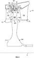
- FIG. 2 illustrates a portion 62 of a gas turbine engine, such as the gas turbine engine 20 of FIG. 1 .
- the portion 62 represents a single stage high pressure turbine ('high pressure turbine') 54.
- 'high pressure turbine' high pressure turbine
- other portions of the gas turbine engine 20 could benefit from the teachings of this disclosure, including but not limited to, the compressor section 24, any additional stage(s) of the high pressure turbine, and the low pressure turbine 46.
- a rotor disk 66 (one rotor disk 66A is shown, although multiple disks could be axially disposed within the portion 62) is mounted to the outer shaft 50 and rotates as a unit with respect to the engine static structure 36.
- the portion 62 includes alternating rows of rotating blades 68 (one blade 68A is shown) is mounted to the rotor disk 66 by a blade root 68R (illustrated schematically).
- Vanes 70A and 70B of vane assemblies 70 are also supported within an outer casing 69 of the engine static structure 36.
- the blade 68A includes a blade tip 68T that is positioned at a radially outermost portion of the blade 68A, a blade root 68R at the radially innermost portion of the blade 68A and a blade body 68B extending therebetween.
- the blade tip 68T extends toward a blade outer air seal (BOAS) assembly 72.
- the blade outer air seal assembly 72 may find beneficial use in many industries including aerospace, industrial, electricity generation, naval propulsion, pumps for gas and oil transmission, aircraft propulsion, vehicle engines and stationary power plants.
- the blade outer air seal assembly 72 is disposed in an annulus radially between the outer casing 69 and the blade tip 68T.
- the blade outer air seal assembly 72 generally includes a support structure 74 and a multitude of blade outer air seal segments 76 (one blade outer air seal segments 76A is shown).
- the blade outer air seal segments 76 may form a full ring hoop assembly that encircles associated blades 68 of a stage of the portion 62.
- the support structure 74 is mounted radially inward from the outer casing 69 and includes forward and aft flanges 78A, 78B that mountably receive the blade outer air seal segments 76.
- the forward flange 78A and the aft flange 78B may be manufactured of a metallic alloy material and may be circumferentially segmented for the receipt of the blade outer air seal segments 76.
- the support structure 74 may establish a cavity 75 that extends axially between the forward flange 78A and the aft flange 78B and radially between the outer casing 69 and the blade outer air seal segment 76A.
- a secondary cooling airflow S may be communicated into the cavity 75 to provide a dedicated source of cooling airflow for cooling the blade outer air seal segments 76.
- the secondary cooling airflow S can be sourced from the high pressure compressor 52 or any other upstream portion of the gas turbine engine 20.
- the secondary cooling airflow S provides a biasing force that biases the blade outer air seal segment 76A radially inward toward the axis A.
- the forward and aft flanges 78A, 78B are portions of the support structure 74 that limit radially inward movement of the blade outer air seal segment 76A due to the biasing force.
- the blade tip 68T may be subject to wear against the blade outer air seal segment 76A, especially during a green (break-in) run, when the blade outer air seal segment 76A may be out of round, e.g., relative to the axis A.
- the disclosed embodiments, shown in FIGS. 3A-3C (discussed in greater detail below) form a core passage 180A and a squealer pocket 200A relatively deeply within the blade body 68B, thereby enabling the forming of wearable tip-rub-portions 210, 230 at the blade tip 68T.
- the wearable tip-rub-portions 210, 230 wear away, the blade outer air seal segment 76A may be rounded as intended for post-green runs. Additionally, the wearable tip-rub-portions 210, 230, once worn away, may expose the core passages 180A and/or 180B.
- the blade body 68B has a pressure side 140 and a suction side 150.
- the pressure and suction sides 140, 150 each extend from a leading edge 160 of the blade body 68B to a trailing edge 170 of the blade body 68B.
- Core passages 180 (first and second core passages 180A, 180B are shown) may be defined within the blade body 68B.
- the core passages 180 may be configured the same as each other in the blade 68A.
- the first core passage 180A will be referred to as the core passage 180A.
- the core passage 180A may extend from the blade root 68R to the blade tip 68T.
- ribs 190 first and second ribs 190A, 190B are shown) may be respectively supported within the core passages 180, radially between the blade root 68R and the blade tip 68T.
- Squealer pockets 200 are located in the blade tip 68T, respectively above the core passages 180.
- the squealer pockets 200 and may be configured the same as each other in the blade 68A.
- the first squealer pocket 200A will be referred to as the squealer pocket 200A.
- Located radially above the squealer pocket 200A is a first wearable tip-rub-portion 210.
- the first wearable tip-rub-portion 210 extends between the pressure side 140 and the suction side 150 ( FIG. 3C ).
- the first wearable tip-rub-portion 210 terminates at a first wearable tip-rub-portion distal end 220.
- a second wearable tip-rub-portion 230 is also located radially above the squealer pocket 200A.
- the second wearable tip-rub-portion 230 extends between the suction side 150 and the pressure side 140 ( FIG. 3C ).
- the second wearable tip-rub-portion 230 terminates at a second wearable tip-rub-portion distal end 240.
- the first and second wearable tip-rub-portion distal ends 220, 240 are spaced from each other to define a wearable tip-rub-portion opening 250.
- the wearable tip-rub-portion opening 250 is in fluid communication with the squealer pocket 200A.
- the first and second wearable tip-rub-portions 210, 230 may be continuous with each other about the leading and trailing edges 160, 170 of the blade body 68B.
- a third wearable tip-rub-portion 215 may extend between the leading edge 160 and the trailing edge 170 ( FIG. 3B ) and a fourth wearable tip-rub-portion 235 may extend between the trailing edge 170 and the leading edge 160 ( FIG. 3B).
- FIG. 3B shows a second wearable tip-rub-portion opening 2502, that is the same as the wearable tip-rub-portion opening 250, formed above the second squealer pocket 200B.
- a first metering tip-portion 260 is located radially between the squealer pocket 200A and the core passage 180A.
- the first metering tip-portion 260 extends between the pressure side 140 and the suction side 150 ( FIG. 3C ).
- the first metering tip-portion 260 terminates at a first metering tip-portion distal end 270 ( FIG. 3C ).
- a second metering tip-portion 280 is also located radially between the squealer pocket 200A and the core passage 180A.
- the second metering tip-portion 280 extends between the suction side 150 and the pressure side 140 ( FIG. 3C ).
- the second metering tip-portion 280 terminates at a second metering tip-portion distal end 290 ( FIG.
- the first and second metering tip-portion distal ends 270, 290 are spaced from each other to define a metering tip-portion opening 300 that is in fluid communication with the squealer pocket 200A. From this configuration, the core passage 180A is in fluid communication with the wearable tip-rub-portion opening 250.
- the first and second metering tip-portions 260, 280 may be continuous with each other about the leading and trailing edges 160, 170 of the blade body 68B.
- a third metering tip-portion 265 may extend between the leading edge 160 and the trailing edge 170 ( FIG. 3B ) and a fourth metering tip-portion 285 may extend between the trailing edge 170 and the leading edge 160 ( FIG. 3B).
- first and second wearable tip-rub-portions 210, 230 and the first and second metering tip-portions 260, 280 may have the same shape, e.g., in a top-down view, along the engine radial axis R ( FIG. 1 ).
- the first and second wearable tip-rub-portions 210, 230 have a first radial thickness 310.
- the first and second metering tip-portions 260, 280 have a second radial thickness 320 that is greater than the first radial thickness 310.
- the squealer pocket 200A has a first radial height 330 that is greater than the second radial thickness 320.
- the first radial height 330 may be sized so that, when the first and second wearable tip-rub-portions 210, 230 have warn away, at least half of the first radial height 330 remains.
- the wearable tip-rub-portion opening 250 has a first axial span 360 and the metering tip-portion opening 300 has a second axial span 350 that is the same as the first axial span 360.
- the squealer pocket 200A has a third axial span 370 that is greater than the first axial span 360.
- FIG. 4 is a flowchart showing a method of shaping the blade outer air seal segment 76A of the gas turbine engine 20.
- the method includes driving the blade 68A about the engine center axis A ( FIG. 1 ).
- the method includes rubbing, from the driving (at block 510), the first (and second) wearable tip-rub-portion 210 and (230), of the blade 68A that are located radially above the squealer pocket 200A against the blade outer air seal segment 76A to shape the blade outer air seal segment 76A.
- the method includes rubbing away, from the driving (at block 510), the first (and second) wearable tip-rub-portion 210 (and 230) to expose the squealer pocket 200A.
Landscapes
- Engineering & Computer Science (AREA)
- Mechanical Engineering (AREA)
- General Engineering & Computer Science (AREA)
- Turbine Rotor Nozzle Sealing (AREA)
Abstract
Description
- Embodiments of the present disclosure pertain to a blade for a gas turbine engine and more specifically to a blade having wearable tip-rub-portions located above a squealer pocket.
- A turbine blade is responsible for extracting energy from the high temperature, high pressure gas produced by the combustor. A squealer pocket formed at a blade tip of the turbine blade may enhance aerodynamic and thermodynamic properties around the blade. The blade tip, including around the squealer pocket, may be subject to wear against a blade outer air seal segment (BOAS), e.g., that is radially adjacent to the blade tip, especially during a green (break-in) run, when the blade outer air seal segment may be out of round.
- According to a first aspect the invention provides a blade for a gas turbine engine including: a blade root; a blade body that extends radially from the blade root to a blade tip, the blade body having a pressure side and a suction side each extending from a leading edge of the blade body to a trailing edge of the blade body; a squealer pocket located in the blade tip; and a first wearable tip-rub-portion located radially above the squealer pocket, and extending between the pressure side and the suction side, the first wearable tip-rub-portion terminating at a first wearable tip-rub-portion distal end.
- Optionally, a second wearable tip-rub-portion is located radially above the squealer pocket, and extending between the suction side and the pressure side; the second wearable tip-rub-portion terminating at a second wearable tip-rub-portion distal end, wherein the first and second wearable tip-rub-portion distal ends are spaced from each other to define a wearable tip-rub-portion opening that is in fluid communication with the squealer pocket; and the first and second wearable tip-rub-portions are continuous with each other about leading and trailing edges of the blade body.
- Optionally, the blade further includes: a core passage defined within the blade body and extending from the blade root to the blade tip; a first metering tip-portion located radially between the squealer pocket and the core passage, and extending between the pressure side and the suction side, the first metering tip-portion terminating at a first metering tip-portion distal end; and a second metering tip-portion located radially between the squealer pocket and the core passage, and extending between the suction side and the pressure side, the second metering tip-portion terminating at a second metering tip-portion distal end, wherein the first and second metering tip-portion distal ends are spaced from each other to define a metering tip-portion opening that is in fluid communication with the squealer pocket, so that the core passage is in fluid communication with the wearable tip-rub-portion opening.
- Optionally, the first and second metering tip-portions are continuous with each other about the leading and trailing edges of the blade body, and wherein the first and second wearable tip-rub-portions and the first and second metering tip-portions have a same shape.
- Optionally, the first and second wearable tip-rub-portions have a first radial thickness in the and the first and second metering tip-portions have a second radial thickness that is greater than the first radial thickness.
- Optionally, the squealer pocket has a first radial height that is greater than the second radial thickness.
- Optionally, the wearable tip-rub-portion opening has a first axial span and the metering tip-portion opening has a second axial span that is the same as the first axial span.
- Optionally, the squealer pocket has a third axial span that is greater than the first axial span.
- Optionally, the blade is a turbine blade.
- According to another aspect the invention provides a gas turbine engine including: a blade that includes: a blade root; a blade body that extends radially from the blade root to a blade tip, the blade body having a pressure side and a suction side each extending from a leading edge of the blade body to a trailing edge of the blade body; a squealer pocket located in the blade tip; and a first wearable tip-rub-portion located radially above the squealer pocket, and extending between the pressure side and the suction side, the first wearable tip-rub-portion terminating at a first wearable tip-rub-portion distal end.
- Optionally, a second wearable tip-rub-portion is located radially above the squealer pocket, and extending between the suction side and the pressure side; the second wearable tip-rub-portion terminating at a second wearable tip-rub-portion distal end, wherein the first and second wearable tip-rub-portion distal ends are spaced from each other to define a wearable tip-rub-portion opening that is in fluid communication with the squealer pocket; and the first and second wearable tip-rub-portions are continuous with each other about leading and trailing edges of the blade body.
- Optionally, a core passage is defined within the blade body and extending from the blade root to the blade tip; a first metering tip-portion located radially between the squealer pocket and the core passage, and extending between the pressure side and the suction side, the first metering tip-portion terminating at a first metering tip-portion distal end; and a second metering tip-portion located radially between the squealer pocket and the core passage, and extending between the suction side and the pressure side, the second metering tip-portion terminating at a second metering tip-portion distal end, wherein the first and second metering tip-portion distal ends are spaced from each other to define a metering tip-portion opening that is in fluid communication with the squealer pocket, so that the core passage is in fluid communication with the wearable tip-rub-portion opening.
- Optionally, the first and second metering tip-portions are continuous with each other about the leading and trailing edges of the blade body, and wherein the first and second wearable tip-rub-portions and the first and second metering tip-portions have a same shape.
- Optionally, the first and second wearable tip-rub-portions have a first radial thickness and the first and second metering tip-portions have a second radial thickness that is greater than the first radial thickness.
- Optionally, the squealer pocket has a first radial height that is greater than the second radial thickness.
- Optionally, the wearable tip-rub-portion opening has a first axial span and the metering tip-portion opening has a second axial span that is the same as the first axial span.
- Optionally, the squealer pocket has a third axial span that is greater than the first axial span.
- Optionally, the gas turbine engine further includes a turbine section, wherein the blade is turbine blade operationally connected to the turbine section.
- According to another aspect the invention provides a method of shaping a blade outer air seal of a gas turbine engine, including: driving a blade about an engine center axis; and rubbing, from the driving, a first wearable tip-rub-portion of the blade that is located radially above a squealer pocket against the blade outer air seal to shape the blade outer air seal.
- Optionally, the method further includes rubbing away, from the driving, the first wearable tip-rub-portion to expose the squealer pocket.
- Certain exemplary embodiments will now be described in greater detail by way of example only with reference to the accompanying drawings. The following descriptions should not be considered limiting in any way. With reference to the accompanying drawings, like elements are numbered alike:
-
FIG. 1 is a partial cross-sectional view of a gas turbine engine; -
FIG. 2 is a partial cross-sectional view of a blade assembly of the gas turbine engine; -
FIG. 3A is partial cross-sectional view of a blade of the gas turbine engine taken alongsection line 3A-3A inFIG. 2 ; -
FIG. 3B is partial cross-sectional view of a blade of the gas turbine engine taken alongsection line 3B-3B inFIG. 3A ; -
FIG. 3C is partial cross-sectional view of a blade of the gas turbine engine taken alongsection line 3C-3C inFIG. 3A ; and -
FIG. 4 is a flowchart showing a method of shaping a blade outer air seal segment according to an embodiment. - A detailed description of one or more embodiments of the disclosed apparatus and method are presented herein by way of exemplification and not limitation with reference to the FIGS.
-
FIG. 1 schematically illustrates agas turbine engine 20. Thegas turbine engine 20 is disclosed herein as a two-spool turbofan that generally incorporates a fan section 22, acompressor section 24, acombustor section 26 and aturbine section 28. Alternative engines might include other systems or features. The fan section 22 drives air along a bypass flow path B in a bypass duct, while thecompressor section 24 drives air along a core flow path C for compression and communication into thecombustor section 26 then expansion through theturbine section 28. Although depicted as a two-spool turbofan gas turbine engine in the disclosed non-limiting embodiment, it should be understood that the concepts described herein are not limited to use with two-spool turbofans as the teachings may be applied to other types of turbine engines including three-spool architectures. - The
exemplary engine 20 generally includes alow speed spool 30 and ahigh speed spool 32 mounted for rotation about an engine central longitudinal axis A (engine radial axis R is also illustrated inFIG. 1 ) relative to an enginestatic structure 36 viaseveral bearing systems 38. It should be understood thatvarious bearing systems 38 at various locations may alternatively or additionally be provided, and the location ofbearing systems 38 may be varied as appropriate to the application. - The
low speed spool 30 generally includes aninner shaft 40 that interconnects afan 42, alow pressure compressor 44 and alow pressure turbine 46. Theinner shaft 40 is connected to thefan 42 through a speed change mechanism, which in exemplarygas turbine engine 20 is illustrated as a gearedarchitecture 48 to drive thefan 42 at a lower speed than thelow speed spool 30. Thehigh speed spool 32 includes anouter shaft 50 that interconnects ahigh pressure compressor 52 andhigh pressure turbine 54. Acombustor 56 is arranged inexemplary gas turbine 20 between thehigh pressure compressor 52 and thehigh pressure turbine 54. An enginestatic structure 36 is arranged generally between thehigh pressure turbine 54 and thelow pressure turbine 46. The enginestatic structure 36 further supports bearingsystems 38 in theturbine section 28. Theinner shaft 40 and theouter shaft 50 are concentric and rotate viabearing systems 38 about the engine central longitudinal axis A which is collinear with their longitudinal axes. - The core airflow is compressed by the
low pressure compressor 44 then thehigh pressure compressor 52, mixed and burned with fuel in thecombustor 56, then expanded over thehigh pressure turbine 54 andlow pressure turbine 46. Theturbines low speed spool 30 andhigh speed spool 32 in response to the expansion. It will be appreciated that each of the positions of the fan section 22,compressor section 24,combustor section 26,turbine section 28, and fandrive gear system 48 may be varied. For example,gear system 48 may be located aft ofcombustor section 26 or even aft ofturbine section 28, and fan section 22 may be positioned forward or aft of the location ofgear system 48. - The
engine 20 in one example is a high bypass geared aircraft engine. In a further example, theengine 20 bypass ratio is greater than about six (6), with an example embodiment being greater than about ten (10), the gearedarchitecture 48 is an epicyclic gear train, such as a planetary gear system or other gear system, with a gear reduction ratio of greater than about 2.3 and thelow pressure turbine 46 has a pressure ratio that is greater than about five. In one disclosed embodiment, theengine 20 bypass ratio is greater than about ten (10:1), the fan diameter is significantly larger than that of thelow pressure compressor 44, and thelow pressure turbine 46 has a pressure ratio that is greater than about five (5:1).Low pressure turbine 46 pressure ratio is pressure measured prior to inlet oflow pressure turbine 46 as related to the pressure at the outlet of thelow pressure turbine 46 prior to an exhaust nozzle. The gearedarchitecture 48 may be an epicyclic gear train, such as a planetary gear system or other gear system, with a gear reduction ratio of greater than about 2.3:1. It should be understood, however, that the above parameters are only exemplary of one embodiment of a geared architecture engine and that the present disclosure is applicable to other gas turbine engines including direct drive turbofans. - A significant amount of thrust is provided by the bypass flow B due to the high bypass ratio. The fan section 22 of the
engine 20 is designed for a particular flight conditiontypically cruise at about 0.8 Mach and about 35,000 feet (about 10,668 meters). The flight condition of 0.8 Mach and 35,000 ft. (10,668 meters), with the engine at its best fuel consumption--also known as "bucket cruise Thrust Specific Fuel Consumption ('TSFC')"--is the industry standard parameter of lbm of fuel being burned divided by lbf of thrust the engine produces at that minimum point. "Low fan pressure ratio" is the pressure ratio across the fan blade alone, without a Fan Exit Guide Vane ("FEGV") system. The low fan pressure ratio as disclosed herein according to one non-limiting embodiment is less than about 1.45. "Low corrected fan tip speed" is the actual fan tip speed in ft/sec divided by an industry standard temperature correction of [(Tram °R)/(518.7 °R)]0.5. The "Low corrected fan tip speed" as disclosed herein according to one non-limiting embodiment is less than about 1150 ft/second (about 350.5 m/sec). -
FIG. 2 illustrates aportion 62 of a gas turbine engine, such as thegas turbine engine 20 ofFIG. 1 . In this exemplary embodiment, theportion 62 represents a single stage high pressure turbine ('high pressure turbine') 54. However, it should be understood that other portions of thegas turbine engine 20 could benefit from the teachings of this disclosure, including but not limited to, thecompressor section 24, any additional stage(s) of the high pressure turbine, and thelow pressure turbine 46. - In this exemplary embodiment, a rotor disk 66 (one
rotor disk 66A is shown, although multiple disks could be axially disposed within the portion 62) is mounted to theouter shaft 50 and rotates as a unit with respect to the enginestatic structure 36. Theportion 62 includes alternating rows of rotating blades 68 (oneblade 68A is shown) is mounted to the rotor disk 66 by ablade root 68R (illustrated schematically).Vanes vane assemblies 70 are also supported within anouter casing 69 of the enginestatic structure 36. - The
blade 68A includes ablade tip 68T that is positioned at a radially outermost portion of theblade 68A, ablade root 68R at the radially innermost portion of theblade 68A and ablade body 68B extending therebetween. Theblade tip 68T extends toward a blade outer air seal (BOAS)assembly 72. The blade outerair seal assembly 72 may find beneficial use in many industries including aerospace, industrial, electricity generation, naval propulsion, pumps for gas and oil transmission, aircraft propulsion, vehicle engines and stationary power plants. - The blade outer
air seal assembly 72 is disposed in an annulus radially between theouter casing 69 and theblade tip 68T. The blade outerair seal assembly 72 generally includes asupport structure 74 and a multitude of blade outer air seal segments 76 (one blade outer air seal segments 76A is shown). The blade outer air seal segments 76 may form a full ring hoop assembly that encircles associated blades 68 of a stage of theportion 62. Thesupport structure 74 is mounted radially inward from theouter casing 69 and includes forward andaft flanges 78A, 78B that mountably receive the blade outer air seal segments 76. Theforward flange 78A and the aft flange 78B may be manufactured of a metallic alloy material and may be circumferentially segmented for the receipt of the blade outer air seal segments 76. - The
support structure 74 may establish acavity 75 that extends axially between theforward flange 78A and the aft flange 78B and radially between theouter casing 69 and the blade outer air seal segment 76A. A secondary cooling airflow S may be communicated into thecavity 75 to provide a dedicated source of cooling airflow for cooling the blade outer air seal segments 76. The secondary cooling airflow S can be sourced from thehigh pressure compressor 52 or any other upstream portion of thegas turbine engine 20. During typical operation, the secondary cooling airflow S provides a biasing force that biases the blade outer air seal segment 76A radially inward toward the axis A. In this example, the forward andaft flanges 78A, 78B are portions of thesupport structure 74 that limit radially inward movement of the blade outer air seal segment 76A due to the biasing force. - As indicated, the
blade tip 68T may be subject to wear against the blade outer air seal segment 76A, especially during a green (break-in) run, when the blade outer air seal segment 76A may be out of round, e.g., relative to the axis A. The disclosed embodiments, shown inFIGS. 3A-3C (discussed in greater detail below) form acore passage 180A and asquealer pocket 200A relatively deeply within theblade body 68B, thereby enabling the forming of wearable tip-rub-portions blade tip 68T. As the wearable tip-rub-portions portions core passages 180A and/or 180B. - Turning now to
FIGS. 3A-3C , theblade body 68B has apressure side 140 and asuction side 150. The pressure andsuction sides leading edge 160 of theblade body 68B to a trailingedge 170 of theblade body 68B. Core passages 180 (first andsecond core passages blade body 68B. The core passages 180 may be configured the same as each other in theblade 68A. For simplicity, thefirst core passage 180A will be referred to as thecore passage 180A. Thecore passage 180A may extend from theblade root 68R to theblade tip 68T. In an embodiment, ribs 190 (first andsecond ribs blade root 68R and theblade tip 68T. - Squealer pockets 200 (first and second squealer pockets 200A, 200B are shown) are located in the
blade tip 68T, respectively above the core passages 180. The squealer pockets 200 and may be configured the same as each other in theblade 68A. For simplicity, thefirst squealer pocket 200A will be referred to as thesquealer pocket 200A. Located radially above thesquealer pocket 200A is a first wearable tip-rub-portion 210. The first wearable tip-rub-portion 210 extends between thepressure side 140 and the suction side 150 (FIG. 3C ). The first wearable tip-rub-portion 210 terminates at a first wearable tip-rub-portiondistal end 220. A second wearable tip-rub-portion 230 is also located radially above thesquealer pocket 200A. The second wearable tip-rub-portion 230 extends between thesuction side 150 and the pressure side 140 (FIG. 3C ). The second wearable tip-rub-portion 230 terminates at a second wearable tip-rub-portiondistal end 240. The first and second wearable tip-rub-portion distal ends 220, 240 are spaced from each other to define a wearable tip-rub-portion opening 250. The wearable tip-rub-portion opening 250 is in fluid communication with thesquealer pocket 200A. The first and second wearable tip-rub-portions edges blade body 68B. For example, a third wearable tip-rub-portion 215 may extend between theleading edge 160 and the trailing edge 170 (FIG. 3B ) and a fourth wearable tip-rub-portion 235 may extend between the trailingedge 170 and the leading edge 160 (FIG. 3B). FIG. 3B shows a second wearable tip-rub-portion opening 2502, that is the same as the wearable tip-rub-portion opening 250, formed above thesecond squealer pocket 200B. - A first metering tip-
portion 260 is located radially between thesquealer pocket 200A and thecore passage 180A. The first metering tip-portion 260 extends between thepressure side 140 and the suction side 150 (FIG. 3C ). The first metering tip-portion 260 terminates at a first metering tip-portion distal end 270 (FIG. 3C ). A second metering tip-portion 280 is also located radially between thesquealer pocket 200A and thecore passage 180A. The second metering tip-portion 280 extends between thesuction side 150 and the pressure side 140 (FIG. 3C ). The second metering tip-portion 280 terminates at a second metering tip-portion distal end 290 (FIG. 3C ). The first and second metering tip-portion distal ends 270, 290 are spaced from each other to define a metering tip-portion opening 300 that is in fluid communication with thesquealer pocket 200A. From this configuration, thecore passage 180A is in fluid communication with the wearable tip-rub-portion opening 250. The first and second metering tip-portions edges blade body 68B. For example, a third metering tip-portion 265 may extend between theleading edge 160 and the trailing edge 170 (FIG. 3B ) and a fourth metering tip-portion 285 may extend between the trailingedge 170 and the leading edge 160 (FIG. 3B). FIG. 3B shows a second metering tip-portion opening 3002, that is the same as the metering tip-portion opening 300, formed between thesecond squealer pocket 200B and thesecond core passage 180B. In addition, the first and second wearable tip-rub-portions portions FIG. 1 ). - As illustrated in
FIG. 3C , in an embodiment, the first and second wearable tip-rub-portions first radial thickness 310. The first and second metering tip-portions second radial thickness 320 that is greater than thefirst radial thickness 310. In an embodiment, thesquealer pocket 200A has a firstradial height 330 that is greater than thesecond radial thickness 320. For example, the firstradial height 330 may be sized so that, when the first and second wearable tip-rub-portions radial height 330 remains. In an embodiment, the wearable tip-rub-portion opening 250 has a firstaxial span 360 and the metering tip-portion opening 300 has a secondaxial span 350 that is the same as the firstaxial span 360. In an embodiment, thesquealer pocket 200A has a thirdaxial span 370 that is greater than the firstaxial span 360. -
FIG. 4 is a flowchart showing a method of shaping the blade outer air seal segment 76A of thegas turbine engine 20. As shown inblock 510, the method includes driving theblade 68A about the engine center axis A (FIG. 1 ). As shown in block 520, the method includes rubbing, from the driving (at block 510), the first (and second) wearable tip-rub-portion 210 and (230), of theblade 68A that are located radially above thesquealer pocket 200A against the blade outer air seal segment 76A to shape the blade outer air seal segment 76A. In addition, as shown inblock 530, the method includes rubbing away, from the driving (at block 510), the first (and second) wearable tip-rub-portion 210 (and 230) to expose thesquealer pocket 200A. - The terminology used herein is for the purpose of describing particular embodiments only and is not intended to be limiting of the present disclosure. As used herein, the singular forms "a", "an" and "the" are intended to include the plural forms as well, unless the context clearly indicates otherwise. It will be further understood that the terms "comprises" and/or "comprising," when used in this specification, specify the presence of stated features, integers, steps, operations, elements, and/or components, but do not preclude the presence or addition of one or more other features, integers, steps, operations, element components, and/or groups thereof.
- While the present disclosure has been described with reference to an exemplary embodiment or embodiments, it will be understood by those skilled in the art that various changes may be made and equivalents may be substituted for elements thereof without departing from the scope of the present invention as defined by the claims. In addition, many modifications may be made to adapt a particular situation or material to the teachings of the present invention without departing from the scope of the claims. Therefore, it is intended that the present invention not be limited to the particular embodiment disclosed as the best mode for carrying out this present disclosure, but that the present disclosure will include all embodiments falling within the scope of the claims.
Claims (13)
- A blade (68A) for a gas turbine engine (20), comprising:a blade root (68R);a blade body (68B) that extends radially from the blade root to a blade tip (68T), the blade body having a pressure side (140) and a suction side (150) each extending from a leading edge (160) of the blade body to a trailing edge (170) of the blade body;a squealer pocket (200A) located in the blade tip;a first wearable tip-rub-portion (210) located radially above the squealer pocket, and extending between the pressure side and the suction side, the first wearable tip-rub-portion terminating at a first wearable tip-rub-portion distal end (220).
- The blade of claim 1, wherein
a second wearable tip-rub-portion (230) is located radially above the squealer pocket (200A), and extending between the suction side (150) and the pressure side (140), the second wearable tip-rub-portion terminating at a second wearable tip-rub-portion distal end (240);
wherein the first and second wearable tip-rub-portion distal ends (220, 240) are spaced from each other to define a wearable tip-rub-portion opening (250) that is in fluid communication with the squealer pocket; and
the first and second wearable tip-rub-portions (210, 230) are continuous with each other about leading and trailing edges (160, 170) of the blade body. - The blade of claim 2, further comprising:a core passage (180A) defined within the blade body (68B) and extending from the blade root (68R) to the blade tip (68T);a first metering tip-portion (260) located radially between the squealer pocket (200A) and the core passage, and extending between the pressure side (140) and the suction side (150), the first metering tip-portion terminating at a first metering tip-portion distal end (270); anda second metering tip-portion (280) located radially between the squealer pocket and the core passage, and extending between the suction side and the pressure side, the second metering tip-portion terminating at a second metering tip-portion distal end (290),wherein the first and second metering tip-portion distal ends are spaced from each other to define a metering tip-portion opening (300) that is in fluid communication with the squealer pocket, so that the core passage is in fluid communication with the wearable tip-rub-portion opening (250).
- The blade of claim 3, wherein
the first and second metering tip-portions (260, 280) are continuous with each other about the leading and trailing edges (160, 170) of the blade body (68B), and
wherein the first and second wearable tip-rub-portions (210, 230) and the first and second metering tip-portions (260, 280) have a same shape. - The blade of claim 3 or 4, wherein
the first and second wearable tip-rub-portions (210, 230) have a first radial thickness (310) in the and the first and second metering tip-portions (260, 280) have a second radial thickness (320) that is greater than the first radial thickness. - The blade of claim 5, wherein
the squealer pocket (200A) has a first radial height (330) that is greater than the second radial thickness (320). - The blade of any of claims 3 to 6, wherein
the wearable tip-rub-portion opening (250) has a first axial span (360) and the metering tip-portion opening has a second axial span (350) that is the same as the first axial span. - The blade of claim 7, wherein
the squealer pocket has a third axial span (370) that is greater than the first axial span (360). - The blade of any preceding claim, wherein
the blade (68A) is a turbine blade. - A gas turbine engine (20), comprising:
a blade (68A) as claimed in any of claims 1 to 8. - The gas turbine engine of claim 10, further comprising
a turbine section (28), wherein the blade (68A) is turbine blade operationally connected to the turbine section. - A method of shaping a blade outer air seal (76A) of a gas turbine engine (20), comprising:driving a blade (68A) about an engine center axis (A); andrubbing, from the driving, a first wearable tip-rub-portion (210) of the blade that is located radially above a squealer pocket (200A) against the blade outer air seal to shape the blade outer air seal.
- The method of claim 12, further comprising
rubbing away, from the driving, the first wearable tip-rub-portion (210) to expose the squealer pocket (200A).
Applications Claiming Priority (1)
| Application Number | Priority Date | Filing Date | Title |
|---|---|---|---|
| US16/781,729 US11215061B2 (en) | 2020-02-04 | 2020-02-04 | Blade with wearable tip-rub-portions above squealer pocket |
Publications (2)
| Publication Number | Publication Date |
|---|---|
| EP3862534A1 true EP3862534A1 (en) | 2021-08-11 |
| EP3862534B1 EP3862534B1 (en) | 2024-01-31 |
Family
ID=74550584
Family Applications (1)
| Application Number | Title | Priority Date | Filing Date |
|---|---|---|---|
| EP21155078.5A Active EP3862534B1 (en) | 2020-02-04 | 2021-02-03 | Blade with wearable tip-rub-portions above squealer pocket |
Country Status (2)
| Country | Link |
|---|---|
| US (1) | US11215061B2 (en) |
| EP (1) | EP3862534B1 (en) |
Citations (4)
| Publication number | Priority date | Publication date | Assignee | Title |
|---|---|---|---|---|
| US5902093A (en) * | 1997-08-22 | 1999-05-11 | General Electric Company | Crack arresting rotor blade |
| WO2016118135A1 (en) * | 2015-01-22 | 2016-07-28 | Siemens Energy, Inc. | Turbine airfoil cooling system with chordwise extending squealer tip cooling channel |
| EP3428397A1 (en) * | 2017-07-13 | 2019-01-16 | General Electric Company | Blade and corresponding method of cooling a tip rail |
| WO2019177600A1 (en) * | 2018-03-14 | 2019-09-19 | General Electric Company | Cooling assembly for a turbine assembly |
Family Cites Families (17)
| Publication number | Priority date | Publication date | Assignee | Title |
|---|---|---|---|---|
| DE2231426C3 (en) * | 1972-06-27 | 1974-11-28 | Motoren- Und Turbinen-Union Muenchen Gmbh, 8000 Muenchen | Shroudless, internally cooled axial turbine rotor blade |
| US4411597A (en) * | 1981-03-20 | 1983-10-25 | The United States Of America As Represented By The Administrator Of The National Aeronautics And Space Administration | Tip cap for a rotor blade |
| DE3203869C2 (en) * | 1982-02-05 | 1984-05-10 | MTU Motoren- und Turbinen-Union München GmbH, 8000 München | Turbine rotor blades for turbo machines, in particular gas turbine engines |
| US4589823A (en) * | 1984-04-27 | 1986-05-20 | General Electric Company | Rotor blade tip |
| US5752802A (en) * | 1996-12-19 | 1998-05-19 | Solar Turbines Incorporated | Sealing apparatus for airfoils of gas turbine engines |
| US6135715A (en) * | 1999-07-29 | 2000-10-24 | General Electric Company | Tip insulated airfoil |
| US7059834B2 (en) * | 2003-01-24 | 2006-06-13 | United Technologies Corporation | Turbine blade |
| FR2934008B1 (en) * | 2008-07-21 | 2015-06-05 | Turbomeca | AUBE HOLLOW TURBINE WHEEL HAVING A RIB |
| US9663404B2 (en) * | 2012-01-03 | 2017-05-30 | General Electric Company | Method of forming a ceramic matrix composite and a ceramic matrix component |
| CN104838092B (en) * | 2012-12-17 | 2017-07-21 | 通用电气公司 | Durable turbo blade |
| GB201222974D0 (en) * | 2012-12-19 | 2013-01-30 | Composite Technology & Applic Ltd | An aerofoil structure |
| DE102013224998A1 (en) * | 2013-12-05 | 2015-06-11 | Rolls-Royce Deutschland Ltd & Co Kg | Turbine rotor blade of a gas turbine and method for cooling a blade tip of a turbine rotor blade of a gas turbine |
| US10400608B2 (en) * | 2016-11-23 | 2019-09-03 | General Electric Company | Cooling structure for a turbine component |
| KR101875683B1 (en) * | 2017-04-04 | 2018-07-06 | 연세대학교 산학협력단 | Gas turbine blade with internal cooling path in discrete multi-cavity rib and rim impingement cooling for enhancing film cooling effectiveness |
| DE102017209421A1 (en) * | 2017-06-02 | 2018-12-06 | MTU Aero Engines AG | Blade with blade tip cooling |
| US10801334B2 (en) * | 2018-09-12 | 2020-10-13 | Raytheon Technologies Corporation | Cooling arrangement with purge partition |
| US11008878B2 (en) * | 2018-12-21 | 2021-05-18 | Rolls-Royce Plc | Turbine blade with ceramic matrix composite aerofoil and metallic root |
-
2020
- 2020-02-04 US US16/781,729 patent/US11215061B2/en active Active
-
2021
- 2021-02-03 EP EP21155078.5A patent/EP3862534B1/en active Active
Patent Citations (4)
| Publication number | Priority date | Publication date | Assignee | Title |
|---|---|---|---|---|
| US5902093A (en) * | 1997-08-22 | 1999-05-11 | General Electric Company | Crack arresting rotor blade |
| WO2016118135A1 (en) * | 2015-01-22 | 2016-07-28 | Siemens Energy, Inc. | Turbine airfoil cooling system with chordwise extending squealer tip cooling channel |
| EP3428397A1 (en) * | 2017-07-13 | 2019-01-16 | General Electric Company | Blade and corresponding method of cooling a tip rail |
| WO2019177600A1 (en) * | 2018-03-14 | 2019-09-19 | General Electric Company | Cooling assembly for a turbine assembly |
Also Published As
| Publication number | Publication date |
|---|---|
| US11215061B2 (en) | 2022-01-04 |
| EP3862534B1 (en) | 2024-01-31 |
| US20210239009A1 (en) | 2021-08-05 |
Similar Documents
| Publication | Publication Date | Title |
|---|---|---|
| EP3734018B1 (en) | Seal for a gas turbine engine component and corresponding method | |
| EP3064711B1 (en) | Component for a gas turbine engine, corresponding gas turbine engine and method of forming an airfoil | |
| EP2981676B1 (en) | Engine component having support with intermediate layer | |
| EP3734019A1 (en) | Labyrinth seal with passive check valve | |
| EP2877709B1 (en) | Blade outer air seal for a gas turbine engine | |
| US10119400B2 (en) | High pressure rotor disk | |
| EP3190266B1 (en) | Gas turbine engine comprising a rotor hub seal | |
| EP3351731B1 (en) | Trailing edge configuration with cast slots and drilled filmholes | |
| EP2932043B1 (en) | Gas turbine engine turbine blade leading edge tip trench cooling | |
| EP2961940B1 (en) | Contoured blade outer air seal for a gas turbine engine | |
| EP3517738B1 (en) | Blade outer air seal for a gas turbine engine | |
| EP3012411B1 (en) | Integrally bladed rotor having axial arm and pocket | |
| US10472981B2 (en) | Edge treatment for gas turbine engine component | |
| EP2935791A1 (en) | Lightweight shrouded fan | |
| EP3862534B1 (en) | Blade with wearable tip-rub-portions above squealer pocket | |
| EP3708778A1 (en) | Inserts for slotted integrally bladed rotor | |
| EP3333369B1 (en) | Fan blade having a tip assembly | |
| EP3971389B1 (en) | Anti-vortex tube retaining ring and bore basket | |
| EP3181828A1 (en) | Blade outer air seal with integrated air shield | |
| EP3091199A1 (en) | Airfoil and corresponding vane | |
| EP3483393B1 (en) | Fan assembly of a gas turbine engine with a tip shroud | |
| EP3388631B1 (en) | Turbine blade and corresponding gas turbine engine | |
| EP3789586B1 (en) | Aerodynamic element assembly for a gas turbine engine | |
| EP4417790A1 (en) | Air foil with staggered cooling hole configuration |
Legal Events
| Date | Code | Title | Description |
|---|---|---|---|
| PUAI | Public reference made under article 153(3) epc to a published international application that has entered the european phase |
Free format text: ORIGINAL CODE: 0009012 |
|
| STAA | Information on the status of an ep patent application or granted ep patent |
Free format text: STATUS: THE APPLICATION HAS BEEN PUBLISHED |
|
| AK | Designated contracting states |
Kind code of ref document: A1 Designated state(s): AL AT BE BG CH CY CZ DE DK EE ES FI FR GB GR HR HU IE IS IT LI LT LU LV MC MK MT NL NO PL PT RO RS SE SI SK SM TR |
|
| STAA | Information on the status of an ep patent application or granted ep patent |
Free format text: STATUS: REQUEST FOR EXAMINATION WAS MADE |
|
| 17P | Request for examination filed |
Effective date: 20220211 |
|
| RBV | Designated contracting states (corrected) |
Designated state(s): AL AT BE BG CH CY CZ DE DK EE ES FI FR GB GR HR HU IE IS IT LI LT LU LV MC MK MT NL NO PL PT RO RS SE SI SK SM TR |
|
| GRAP | Despatch of communication of intention to grant a patent |
Free format text: ORIGINAL CODE: EPIDOSNIGR1 |
|
| STAA | Information on the status of an ep patent application or granted ep patent |
Free format text: STATUS: GRANT OF PATENT IS INTENDED |
|
| INTG | Intention to grant announced |
Effective date: 20230809 |
|
| RAP3 | Party data changed (applicant data changed or rights of an application transferred) |
Owner name: RTX CORPORATION |
|
| GRAS | Grant fee paid |
Free format text: ORIGINAL CODE: EPIDOSNIGR3 |
|
| GRAA | (expected) grant |
Free format text: ORIGINAL CODE: 0009210 |
|
| STAA | Information on the status of an ep patent application or granted ep patent |
Free format text: STATUS: THE PATENT HAS BEEN GRANTED |
|
| AK | Designated contracting states |
Kind code of ref document: B1 Designated state(s): AL AT BE BG CH CY CZ DE DK EE ES FI FR GB GR HR HU IE IS IT LI LT LU LV MC MK MT NL NO PL PT RO RS SE SI SK SM TR |
|
| REG | Reference to a national code |
Ref country code: GB Ref legal event code: FG4D Ref country code: CH Ref legal event code: EP |
|
| REG | Reference to a national code |
Ref country code: DE Ref legal event code: R096 Ref document number: 602021008809 Country of ref document: DE |
|
| REG | Reference to a national code |
Ref country code: IE Ref legal event code: FG4D |
|
| REG | Reference to a national code |
Ref country code: LT Ref legal event code: MG9D |
|
| REG | Reference to a national code |
Ref country code: NL Ref legal event code: MP Effective date: 20240131 |
|
| PG25 | Lapsed in a contracting state [announced via postgrant information from national office to epo] |
Ref country code: IS Free format text: LAPSE BECAUSE OF FAILURE TO SUBMIT A TRANSLATION OF THE DESCRIPTION OR TO PAY THE FEE WITHIN THE PRESCRIBED TIME-LIMIT Effective date: 20240531 |
|
| PG25 | Lapsed in a contracting state [announced via postgrant information from national office to epo] |
Ref country code: LT Free format text: LAPSE BECAUSE OF FAILURE TO SUBMIT A TRANSLATION OF THE DESCRIPTION OR TO PAY THE FEE WITHIN THE PRESCRIBED TIME-LIMIT Effective date: 20240131 |
|
| PG25 | Lapsed in a contracting state [announced via postgrant information from national office to epo] |
Ref country code: GR Free format text: LAPSE BECAUSE OF FAILURE TO SUBMIT A TRANSLATION OF THE DESCRIPTION OR TO PAY THE FEE WITHIN THE PRESCRIBED TIME-LIMIT Effective date: 20240501 |
|
| REG | Reference to a national code |
Ref country code: AT Ref legal event code: MK05 Ref document number: 1654003 Country of ref document: AT Kind code of ref document: T Effective date: 20240131 |
|
| PG25 | Lapsed in a contracting state [announced via postgrant information from national office to epo] |
Ref country code: RS Free format text: LAPSE BECAUSE OF FAILURE TO SUBMIT A TRANSLATION OF THE DESCRIPTION OR TO PAY THE FEE WITHIN THE PRESCRIBED TIME-LIMIT Effective date: 20240430 Ref country code: HR Free format text: LAPSE BECAUSE OF FAILURE TO SUBMIT A TRANSLATION OF THE DESCRIPTION OR TO PAY THE FEE WITHIN THE PRESCRIBED TIME-LIMIT Effective date: 20240131 Ref country code: NL Free format text: LAPSE BECAUSE OF FAILURE TO SUBMIT A TRANSLATION OF THE DESCRIPTION OR TO PAY THE FEE WITHIN THE PRESCRIBED TIME-LIMIT Effective date: 20240131 |
|
| PG25 | Lapsed in a contracting state [announced via postgrant information from national office to epo] |
Ref country code: ES Free format text: LAPSE BECAUSE OF FAILURE TO SUBMIT A TRANSLATION OF THE DESCRIPTION OR TO PAY THE FEE WITHIN THE PRESCRIBED TIME-LIMIT Effective date: 20240131 |
|
| PG25 | Lapsed in a contracting state [announced via postgrant information from national office to epo] |
Ref country code: AT Free format text: LAPSE BECAUSE OF FAILURE TO SUBMIT A TRANSLATION OF THE DESCRIPTION OR TO PAY THE FEE WITHIN THE PRESCRIBED TIME-LIMIT Effective date: 20240131 |
|
| PG25 | Lapsed in a contracting state [announced via postgrant information from national office to epo] |
Ref country code: RS Free format text: LAPSE BECAUSE OF FAILURE TO SUBMIT A TRANSLATION OF THE DESCRIPTION OR TO PAY THE FEE WITHIN THE PRESCRIBED TIME-LIMIT Effective date: 20240430 Ref country code: NO Free format text: LAPSE BECAUSE OF FAILURE TO SUBMIT A TRANSLATION OF THE DESCRIPTION OR TO PAY THE FEE WITHIN THE PRESCRIBED TIME-LIMIT Effective date: 20240430 Ref country code: NL Free format text: LAPSE BECAUSE OF FAILURE TO SUBMIT A TRANSLATION OF THE DESCRIPTION OR TO PAY THE FEE WITHIN THE PRESCRIBED TIME-LIMIT Effective date: 20240131 Ref country code: LT Free format text: LAPSE BECAUSE OF FAILURE TO SUBMIT A TRANSLATION OF THE DESCRIPTION OR TO PAY THE FEE WITHIN THE PRESCRIBED TIME-LIMIT Effective date: 20240131 Ref country code: IS Free format text: LAPSE BECAUSE OF FAILURE TO SUBMIT A TRANSLATION OF THE DESCRIPTION OR TO PAY THE FEE WITHIN THE PRESCRIBED TIME-LIMIT Effective date: 20240531 Ref country code: HR Free format text: LAPSE BECAUSE OF FAILURE TO SUBMIT A TRANSLATION OF THE DESCRIPTION OR TO PAY THE FEE WITHIN THE PRESCRIBED TIME-LIMIT Effective date: 20240131 Ref country code: GR Free format text: LAPSE BECAUSE OF FAILURE TO SUBMIT A TRANSLATION OF THE DESCRIPTION OR TO PAY THE FEE WITHIN THE PRESCRIBED TIME-LIMIT Effective date: 20240501 Ref country code: FI Free format text: LAPSE BECAUSE OF FAILURE TO SUBMIT A TRANSLATION OF THE DESCRIPTION OR TO PAY THE FEE WITHIN THE PRESCRIBED TIME-LIMIT Effective date: 20240131 Ref country code: ES Free format text: LAPSE BECAUSE OF FAILURE TO SUBMIT A TRANSLATION OF THE DESCRIPTION OR TO PAY THE FEE WITHIN THE PRESCRIBED TIME-LIMIT Effective date: 20240131 Ref country code: BG Free format text: LAPSE BECAUSE OF FAILURE TO SUBMIT A TRANSLATION OF THE DESCRIPTION OR TO PAY THE FEE WITHIN THE PRESCRIBED TIME-LIMIT Effective date: 20240131 Ref country code: AT Free format text: LAPSE BECAUSE OF FAILURE TO SUBMIT A TRANSLATION OF THE DESCRIPTION OR TO PAY THE FEE WITHIN THE PRESCRIBED TIME-LIMIT Effective date: 20240131 |
|
| PG25 | Lapsed in a contracting state [announced via postgrant information from national office to epo] |
Ref country code: PL Free format text: LAPSE BECAUSE OF FAILURE TO SUBMIT A TRANSLATION OF THE DESCRIPTION OR TO PAY THE FEE WITHIN THE PRESCRIBED TIME-LIMIT Effective date: 20240131 Ref country code: PT Free format text: LAPSE BECAUSE OF FAILURE TO SUBMIT A TRANSLATION OF THE DESCRIPTION OR TO PAY THE FEE WITHIN THE PRESCRIBED TIME-LIMIT Effective date: 20240531 |
|
| PG25 | Lapsed in a contracting state [announced via postgrant information from national office to epo] |
Ref country code: SE Free format text: LAPSE BECAUSE OF FAILURE TO SUBMIT A TRANSLATION OF THE DESCRIPTION OR TO PAY THE FEE WITHIN THE PRESCRIBED TIME-LIMIT Effective date: 20240131 Ref country code: PT Free format text: LAPSE BECAUSE OF FAILURE TO SUBMIT A TRANSLATION OF THE DESCRIPTION OR TO PAY THE FEE WITHIN THE PRESCRIBED TIME-LIMIT Effective date: 20240531 Ref country code: PL Free format text: LAPSE BECAUSE OF FAILURE TO SUBMIT A TRANSLATION OF THE DESCRIPTION OR TO PAY THE FEE WITHIN THE PRESCRIBED TIME-LIMIT Effective date: 20240131 Ref country code: LV Free format text: LAPSE BECAUSE OF FAILURE TO SUBMIT A TRANSLATION OF THE DESCRIPTION OR TO PAY THE FEE WITHIN THE PRESCRIBED TIME-LIMIT Effective date: 20240131 |
|
| REG | Reference to a national code |
Ref country code: CH Ref legal event code: PL |
|
| PG25 | Lapsed in a contracting state [announced via postgrant information from national office to epo] |
Ref country code: DK Free format text: LAPSE BECAUSE OF FAILURE TO SUBMIT A TRANSLATION OF THE DESCRIPTION OR TO PAY THE FEE WITHIN THE PRESCRIBED TIME-LIMIT Effective date: 20240131 |
|
| PG25 | Lapsed in a contracting state [announced via postgrant information from national office to epo] |
Ref country code: SM Free format text: LAPSE BECAUSE OF FAILURE TO SUBMIT A TRANSLATION OF THE DESCRIPTION OR TO PAY THE FEE WITHIN THE PRESCRIBED TIME-LIMIT Effective date: 20240131 |
|
| PG25 | Lapsed in a contracting state [announced via postgrant information from national office to epo] |
Ref country code: LU Free format text: LAPSE BECAUSE OF NON-PAYMENT OF DUE FEES Effective date: 20240203 |
|
| PG25 | Lapsed in a contracting state [announced via postgrant information from national office to epo] |
Ref country code: CH Free format text: LAPSE BECAUSE OF NON-PAYMENT OF DUE FEES Effective date: 20240229 |
|
| PG25 | Lapsed in a contracting state [announced via postgrant information from national office to epo] |
Ref country code: CZ Free format text: LAPSE BECAUSE OF FAILURE TO SUBMIT A TRANSLATION OF THE DESCRIPTION OR TO PAY THE FEE WITHIN THE PRESCRIBED TIME-LIMIT Effective date: 20240131 Ref country code: EE Free format text: LAPSE BECAUSE OF FAILURE TO SUBMIT A TRANSLATION OF THE DESCRIPTION OR TO PAY THE FEE WITHIN THE PRESCRIBED TIME-LIMIT Effective date: 20240131 |
|
| PG25 | Lapsed in a contracting state [announced via postgrant information from national office to epo] |
Ref country code: SK Free format text: LAPSE BECAUSE OF FAILURE TO SUBMIT A TRANSLATION OF THE DESCRIPTION OR TO PAY THE FEE WITHIN THE PRESCRIBED TIME-LIMIT Effective date: 20240131 |
|
| PG25 | Lapsed in a contracting state [announced via postgrant information from national office to epo] |
Ref country code: SM Free format text: LAPSE BECAUSE OF FAILURE TO SUBMIT A TRANSLATION OF THE DESCRIPTION OR TO PAY THE FEE WITHIN THE PRESCRIBED TIME-LIMIT Effective date: 20240131 Ref country code: SK Free format text: LAPSE BECAUSE OF FAILURE TO SUBMIT A TRANSLATION OF THE DESCRIPTION OR TO PAY THE FEE WITHIN THE PRESCRIBED TIME-LIMIT Effective date: 20240131 Ref country code: RO Free format text: LAPSE BECAUSE OF FAILURE TO SUBMIT A TRANSLATION OF THE DESCRIPTION OR TO PAY THE FEE WITHIN THE PRESCRIBED TIME-LIMIT Effective date: 20240131 Ref country code: LU Free format text: LAPSE BECAUSE OF NON-PAYMENT OF DUE FEES Effective date: 20240203 Ref country code: EE Free format text: LAPSE BECAUSE OF FAILURE TO SUBMIT A TRANSLATION OF THE DESCRIPTION OR TO PAY THE FEE WITHIN THE PRESCRIBED TIME-LIMIT Effective date: 20240131 Ref country code: DK Free format text: LAPSE BECAUSE OF FAILURE TO SUBMIT A TRANSLATION OF THE DESCRIPTION OR TO PAY THE FEE WITHIN THE PRESCRIBED TIME-LIMIT Effective date: 20240131 Ref country code: CZ Free format text: LAPSE BECAUSE OF FAILURE TO SUBMIT A TRANSLATION OF THE DESCRIPTION OR TO PAY THE FEE WITHIN THE PRESCRIBED TIME-LIMIT Effective date: 20240131 Ref country code: CH Free format text: LAPSE BECAUSE OF NON-PAYMENT OF DUE FEES Effective date: 20240229 |
|
| REG | Reference to a national code |
Ref country code: DE Ref legal event code: R097 Ref document number: 602021008809 Country of ref document: DE |
|
| PG25 | Lapsed in a contracting state [announced via postgrant information from national office to epo] |
Ref country code: MC Free format text: LAPSE BECAUSE OF FAILURE TO SUBMIT A TRANSLATION OF THE DESCRIPTION OR TO PAY THE FEE WITHIN THE PRESCRIBED TIME-LIMIT Effective date: 20240131 |
|
| PG25 | Lapsed in a contracting state [announced via postgrant information from national office to epo] |
Ref country code: MC Free format text: LAPSE BECAUSE OF FAILURE TO SUBMIT A TRANSLATION OF THE DESCRIPTION OR TO PAY THE FEE WITHIN THE PRESCRIBED TIME-LIMIT Effective date: 20240131 |
|
| PG25 | Lapsed in a contracting state [announced via postgrant information from national office to epo] |
Ref country code: IT Free format text: LAPSE BECAUSE OF FAILURE TO SUBMIT A TRANSLATION OF THE DESCRIPTION OR TO PAY THE FEE WITHIN THE PRESCRIBED TIME-LIMIT Effective date: 20240131 |
|
| PLBE | No opposition filed within time limit |
Free format text: ORIGINAL CODE: 0009261 |
|
| STAA | Information on the status of an ep patent application or granted ep patent |
Free format text: STATUS: NO OPPOSITION FILED WITHIN TIME LIMIT |
|
| REG | Reference to a national code |
Ref country code: BE Ref legal event code: MM Effective date: 20240229 |
|
| PG25 | Lapsed in a contracting state [announced via postgrant information from national office to epo] |
Ref country code: IT Free format text: LAPSE BECAUSE OF FAILURE TO SUBMIT A TRANSLATION OF THE DESCRIPTION OR TO PAY THE FEE WITHIN THE PRESCRIBED TIME-LIMIT Effective date: 20240131 |
|
| 26N | No opposition filed |
Effective date: 20241101 |
|
| PG25 | Lapsed in a contracting state [announced via postgrant information from national office to epo] |
Ref country code: BE Free format text: LAPSE BECAUSE OF NON-PAYMENT OF DUE FEES Effective date: 20240229 |
|
| PG25 | Lapsed in a contracting state [announced via postgrant information from national office to epo] |
Ref country code: IE Free format text: LAPSE BECAUSE OF NON-PAYMENT OF DUE FEES Effective date: 20240203 |
|
| PG25 | Lapsed in a contracting state [announced via postgrant information from national office to epo] |
Ref country code: IE Free format text: LAPSE BECAUSE OF NON-PAYMENT OF DUE FEES Effective date: 20240203 Ref country code: BE Free format text: LAPSE BECAUSE OF NON-PAYMENT OF DUE FEES Effective date: 20240229 |
|
| PG25 | Lapsed in a contracting state [announced via postgrant information from national office to epo] |
Ref country code: SI Free format text: LAPSE BECAUSE OF FAILURE TO SUBMIT A TRANSLATION OF THE DESCRIPTION OR TO PAY THE FEE WITHIN THE PRESCRIBED TIME-LIMIT Effective date: 20240131 |
|
| PG25 | Lapsed in a contracting state [announced via postgrant information from national office to epo] |
Ref country code: CY Free format text: LAPSE BECAUSE OF FAILURE TO SUBMIT A TRANSLATION OF THE DESCRIPTION OR TO PAY THE FEE WITHIN THE PRESCRIBED TIME-LIMIT; INVALID AB INITIO Effective date: 20210203 |
|
| PG25 | Lapsed in a contracting state [announced via postgrant information from national office to epo] |
Ref country code: HU Free format text: LAPSE BECAUSE OF FAILURE TO SUBMIT A TRANSLATION OF THE DESCRIPTION OR TO PAY THE FEE WITHIN THE PRESCRIBED TIME-LIMIT; INVALID AB INITIO Effective date: 20210203 |
|
| PG25 | Lapsed in a contracting state [announced via postgrant information from national office to epo] |
Ref country code: TR Free format text: LAPSE BECAUSE OF FAILURE TO SUBMIT A TRANSLATION OF THE DESCRIPTION OR TO PAY THE FEE WITHIN THE PRESCRIBED TIME-LIMIT Effective date: 20240131 |
|
| PGFP | Annual fee paid to national office [announced via postgrant information from national office to epo] |
Ref country code: GB Payment date: 20260121 Year of fee payment: 6 |
|
| PGFP | Annual fee paid to national office [announced via postgrant information from national office to epo] |
Ref country code: DE Payment date: 20260121 Year of fee payment: 6 |
|
| PGFP | Annual fee paid to national office [announced via postgrant information from national office to epo] |
Ref country code: FR Payment date: 20260121 Year of fee payment: 6 |