EP3862338A1 - Environmental barrier coating - Google Patents
Environmental barrier coating Download PDFInfo
- Publication number
- EP3862338A1 EP3862338A1 EP21155329.2A EP21155329A EP3862338A1 EP 3862338 A1 EP3862338 A1 EP 3862338A1 EP 21155329 A EP21155329 A EP 21155329A EP 3862338 A1 EP3862338 A1 EP 3862338A1
- Authority
- EP
- European Patent Office
- Prior art keywords
- particles
- gettering
- barrier layer
- article
- microns
- Prior art date
- Legal status (The legal status is an assumption and is not a legal conclusion. Google has not performed a legal analysis and makes no representation as to the accuracy of the status listed.)
- Pending
Links
Images

Classifications
-
- C—CHEMISTRY; METALLURGY
- C04—CEMENTS; CONCRETE; ARTIFICIAL STONE; CERAMICS; REFRACTORIES
- C04B—LIME, MAGNESIA; SLAG; CEMENTS; COMPOSITIONS THEREOF, e.g. MORTARS, CONCRETE OR LIKE BUILDING MATERIALS; ARTIFICIAL STONE; CERAMICS; REFRACTORIES; TREATMENT OF NATURAL STONE
- C04B41/00—After-treatment of mortars, concrete, artificial stone or ceramics; Treatment of natural stone
- C04B41/009—After-treatment of mortars, concrete, artificial stone or ceramics; Treatment of natural stone characterised by the material treated
-
- C—CHEMISTRY; METALLURGY
- C04—CEMENTS; CONCRETE; ARTIFICIAL STONE; CERAMICS; REFRACTORIES
- C04B—LIME, MAGNESIA; SLAG; CEMENTS; COMPOSITIONS THEREOF, e.g. MORTARS, CONCRETE OR LIKE BUILDING MATERIALS; ARTIFICIAL STONE; CERAMICS; REFRACTORIES; TREATMENT OF NATURAL STONE
- C04B41/00—After-treatment of mortars, concrete, artificial stone or ceramics; Treatment of natural stone
- C04B41/80—After-treatment of mortars, concrete, artificial stone or ceramics; Treatment of natural stone of only ceramics
- C04B41/81—Coating or impregnation
- C04B41/85—Coating or impregnation with inorganic materials
- C04B41/87—Ceramics
-
- C—CHEMISTRY; METALLURGY
- C04—CEMENTS; CONCRETE; ARTIFICIAL STONE; CERAMICS; REFRACTORIES
- C04B—LIME, MAGNESIA; SLAG; CEMENTS; COMPOSITIONS THEREOF, e.g. MORTARS, CONCRETE OR LIKE BUILDING MATERIALS; ARTIFICIAL STONE; CERAMICS; REFRACTORIES; TREATMENT OF NATURAL STONE
- C04B35/00—Shaped ceramic products characterised by their composition; Ceramics compositions; Processing powders of inorganic compounds preparatory to the manufacturing of ceramic products
- C04B35/71—Ceramic products containing macroscopic reinforcing agents
- C04B35/78—Ceramic products containing macroscopic reinforcing agents containing non-metallic materials
-
- C—CHEMISTRY; METALLURGY
- C04—CEMENTS; CONCRETE; ARTIFICIAL STONE; CERAMICS; REFRACTORIES
- C04B—LIME, MAGNESIA; SLAG; CEMENTS; COMPOSITIONS THEREOF, e.g. MORTARS, CONCRETE OR LIKE BUILDING MATERIALS; ARTIFICIAL STONE; CERAMICS; REFRACTORIES; TREATMENT OF NATURAL STONE
- C04B41/00—After-treatment of mortars, concrete, artificial stone or ceramics; Treatment of natural stone
- C04B41/45—Coating or impregnating, e.g. injection in masonry, partial coating of green or fired ceramics, organic coating compositions for adhering together two concrete elements
- C04B41/4505—Coating or impregnating, e.g. injection in masonry, partial coating of green or fired ceramics, organic coating compositions for adhering together two concrete elements characterised by the method of application
- C04B41/4535—Coating or impregnating, e.g. injection in masonry, partial coating of green or fired ceramics, organic coating compositions for adhering together two concrete elements characterised by the method of application applied as a solution, emulsion, dispersion or suspension
- C04B41/4543—Coating or impregnating, e.g. injection in masonry, partial coating of green or fired ceramics, organic coating compositions for adhering together two concrete elements characterised by the method of application applied as a solution, emulsion, dispersion or suspension by spraying, e.g. by atomising
-
- C—CHEMISTRY; METALLURGY
- C04—CEMENTS; CONCRETE; ARTIFICIAL STONE; CERAMICS; REFRACTORIES
- C04B—LIME, MAGNESIA; SLAG; CEMENTS; COMPOSITIONS THEREOF, e.g. MORTARS, CONCRETE OR LIKE BUILDING MATERIALS; ARTIFICIAL STONE; CERAMICS; REFRACTORIES; TREATMENT OF NATURAL STONE
- C04B41/00—After-treatment of mortars, concrete, artificial stone or ceramics; Treatment of natural stone
- C04B41/45—Coating or impregnating, e.g. injection in masonry, partial coating of green or fired ceramics, organic coating compositions for adhering together two concrete elements
- C04B41/50—Coating or impregnating, e.g. injection in masonry, partial coating of green or fired ceramics, organic coating compositions for adhering together two concrete elements with inorganic materials
- C04B41/5024—Silicates
-
- C—CHEMISTRY; METALLURGY
- C04—CEMENTS; CONCRETE; ARTIFICIAL STONE; CERAMICS; REFRACTORIES
- C04B—LIME, MAGNESIA; SLAG; CEMENTS; COMPOSITIONS THEREOF, e.g. MORTARS, CONCRETE OR LIKE BUILDING MATERIALS; ARTIFICIAL STONE; CERAMICS; REFRACTORIES; TREATMENT OF NATURAL STONE
- C04B41/00—After-treatment of mortars, concrete, artificial stone or ceramics; Treatment of natural stone
- C04B41/45—Coating or impregnating, e.g. injection in masonry, partial coating of green or fired ceramics, organic coating compositions for adhering together two concrete elements
- C04B41/50—Coating or impregnating, e.g. injection in masonry, partial coating of green or fired ceramics, organic coating compositions for adhering together two concrete elements with inorganic materials
- C04B41/5025—Coating or impregnating, e.g. injection in masonry, partial coating of green or fired ceramics, organic coating compositions for adhering together two concrete elements with inorganic materials with ceramic materials
- C04B41/5035—Silica
-
- C—CHEMISTRY; METALLURGY
- C04—CEMENTS; CONCRETE; ARTIFICIAL STONE; CERAMICS; REFRACTORIES
- C04B—LIME, MAGNESIA; SLAG; CEMENTS; COMPOSITIONS THEREOF, e.g. MORTARS, CONCRETE OR LIKE BUILDING MATERIALS; ARTIFICIAL STONE; CERAMICS; REFRACTORIES; TREATMENT OF NATURAL STONE
- C04B41/00—After-treatment of mortars, concrete, artificial stone or ceramics; Treatment of natural stone
- C04B41/45—Coating or impregnating, e.g. injection in masonry, partial coating of green or fired ceramics, organic coating compositions for adhering together two concrete elements
- C04B41/50—Coating or impregnating, e.g. injection in masonry, partial coating of green or fired ceramics, organic coating compositions for adhering together two concrete elements with inorganic materials
- C04B41/5053—Coating or impregnating, e.g. injection in masonry, partial coating of green or fired ceramics, organic coating compositions for adhering together two concrete elements with inorganic materials non-oxide ceramics
- C04B41/5057—Carbides
- C04B41/5059—Silicon carbide
-
- C—CHEMISTRY; METALLURGY
- C04—CEMENTS; CONCRETE; ARTIFICIAL STONE; CERAMICS; REFRACTORIES
- C04B—LIME, MAGNESIA; SLAG; CEMENTS; COMPOSITIONS THEREOF, e.g. MORTARS, CONCRETE OR LIKE BUILDING MATERIALS; ARTIFICIAL STONE; CERAMICS; REFRACTORIES; TREATMENT OF NATURAL STONE
- C04B41/00—After-treatment of mortars, concrete, artificial stone or ceramics; Treatment of natural stone
- C04B41/45—Coating or impregnating, e.g. injection in masonry, partial coating of green or fired ceramics, organic coating compositions for adhering together two concrete elements
- C04B41/50—Coating or impregnating, e.g. injection in masonry, partial coating of green or fired ceramics, organic coating compositions for adhering together two concrete elements with inorganic materials
- C04B41/5076—Coating or impregnating, e.g. injection in masonry, partial coating of green or fired ceramics, organic coating compositions for adhering together two concrete elements with inorganic materials with masses bonded by inorganic cements
- C04B41/5089—Silica sols, alkyl, ammonium or alkali metal silicate cements
-
- C—CHEMISTRY; METALLURGY
- C04—CEMENTS; CONCRETE; ARTIFICIAL STONE; CERAMICS; REFRACTORIES
- C04B—LIME, MAGNESIA; SLAG; CEMENTS; COMPOSITIONS THEREOF, e.g. MORTARS, CONCRETE OR LIKE BUILDING MATERIALS; ARTIFICIAL STONE; CERAMICS; REFRACTORIES; TREATMENT OF NATURAL STONE
- C04B41/00—After-treatment of mortars, concrete, artificial stone or ceramics; Treatment of natural stone
- C04B41/45—Coating or impregnating, e.g. injection in masonry, partial coating of green or fired ceramics, organic coating compositions for adhering together two concrete elements
- C04B41/52—Multiple coating or impregnating multiple coating or impregnating with the same composition or with compositions only differing in the concentration of the constituents, is classified as single coating or impregnation
-
- C—CHEMISTRY; METALLURGY
- C04—CEMENTS; CONCRETE; ARTIFICIAL STONE; CERAMICS; REFRACTORIES
- C04B—LIME, MAGNESIA; SLAG; CEMENTS; COMPOSITIONS THEREOF, e.g. MORTARS, CONCRETE OR LIKE BUILDING MATERIALS; ARTIFICIAL STONE; CERAMICS; REFRACTORIES; TREATMENT OF NATURAL STONE
- C04B41/00—After-treatment of mortars, concrete, artificial stone or ceramics; Treatment of natural stone
- C04B41/80—After-treatment of mortars, concrete, artificial stone or ceramics; Treatment of natural stone of only ceramics
- C04B41/81—Coating or impregnation
- C04B41/89—Coating or impregnation for obtaining at least two superposed coatings having different compositions
-
- F—MECHANICAL ENGINEERING; LIGHTING; HEATING; WEAPONS; BLASTING
- F01—MACHINES OR ENGINES IN GENERAL; ENGINE PLANTS IN GENERAL; STEAM ENGINES
- F01D—NON-POSITIVE DISPLACEMENT MACHINES OR ENGINES, e.g. STEAM TURBINES
- F01D5/00—Blades; Blade-carrying members; Heating, heat-insulating, cooling or antivibration means on the blades or the members
- F01D5/12—Blades
- F01D5/28—Selecting particular materials; Particular measures relating thereto; Measures against erosion or corrosion
- F01D5/284—Selection of ceramic materials
-
- F—MECHANICAL ENGINEERING; LIGHTING; HEATING; WEAPONS; BLASTING
- F01—MACHINES OR ENGINES IN GENERAL; ENGINE PLANTS IN GENERAL; STEAM ENGINES
- F01D—NON-POSITIVE DISPLACEMENT MACHINES OR ENGINES, e.g. STEAM TURBINES
- F01D5/00—Blades; Blade-carrying members; Heating, heat-insulating, cooling or antivibration means on the blades or the members
- F01D5/12—Blades
- F01D5/28—Selecting particular materials; Particular measures relating thereto; Measures against erosion or corrosion
- F01D5/288—Protective coatings for blades
-
- F—MECHANICAL ENGINEERING; LIGHTING; HEATING; WEAPONS; BLASTING
- F05—INDEXING SCHEMES RELATING TO ENGINES OR PUMPS IN VARIOUS SUBCLASSES OF CLASSES F01-F04
- F05D—INDEXING SCHEME FOR ASPECTS RELATING TO NON-POSITIVE-DISPLACEMENT MACHINES OR ENGINES, GAS-TURBINES OR JET-PROPULSION PLANTS
- F05D2230/00—Manufacture
- F05D2230/90—Coating; Surface treatment
-
- F—MECHANICAL ENGINEERING; LIGHTING; HEATING; WEAPONS; BLASTING
- F05—INDEXING SCHEMES RELATING TO ENGINES OR PUMPS IN VARIOUS SUBCLASSES OF CLASSES F01-F04
- F05D—INDEXING SCHEME FOR ASPECTS RELATING TO NON-POSITIVE-DISPLACEMENT MACHINES OR ENGINES, GAS-TURBINES OR JET-PROPULSION PLANTS
- F05D2300/00—Materials; Properties thereof
- F05D2300/20—Oxide or non-oxide ceramics
- F05D2300/21—Oxide ceramics
- F05D2300/211—Silica
-
- F—MECHANICAL ENGINEERING; LIGHTING; HEATING; WEAPONS; BLASTING
- F05—INDEXING SCHEMES RELATING TO ENGINES OR PUMPS IN VARIOUS SUBCLASSES OF CLASSES F01-F04
- F05D—INDEXING SCHEME FOR ASPECTS RELATING TO NON-POSITIVE-DISPLACEMENT MACHINES OR ENGINES, GAS-TURBINES OR JET-PROPULSION PLANTS
- F05D2300/00—Materials; Properties thereof
- F05D2300/20—Oxide or non-oxide ceramics
- F05D2300/22—Non-oxide ceramics
- F05D2300/226—Carbides
- F05D2300/2261—Carbides of silicon
-
- F—MECHANICAL ENGINEERING; LIGHTING; HEATING; WEAPONS; BLASTING
- F05—INDEXING SCHEMES RELATING TO ENGINES OR PUMPS IN VARIOUS SUBCLASSES OF CLASSES F01-F04
- F05D—INDEXING SCHEME FOR ASPECTS RELATING TO NON-POSITIVE-DISPLACEMENT MACHINES OR ENGINES, GAS-TURBINES OR JET-PROPULSION PLANTS
- F05D2300/00—Materials; Properties thereof
- F05D2300/60—Properties or characteristics given to material by treatment or manufacturing
- F05D2300/603—Composites; e.g. fibre-reinforced
- F05D2300/6033—Ceramic matrix composites [CMC]
-
- F—MECHANICAL ENGINEERING; LIGHTING; HEATING; WEAPONS; BLASTING
- F05—INDEXING SCHEMES RELATING TO ENGINES OR PUMPS IN VARIOUS SUBCLASSES OF CLASSES F01-F04
- F05D—INDEXING SCHEME FOR ASPECTS RELATING TO NON-POSITIVE-DISPLACEMENT MACHINES OR ENGINES, GAS-TURBINES OR JET-PROPULSION PLANTS
- F05D2300/00—Materials; Properties thereof
- F05D2300/60—Properties or characteristics given to material by treatment or manufacturing
- F05D2300/609—Grain size
-
- F—MECHANICAL ENGINEERING; LIGHTING; HEATING; WEAPONS; BLASTING
- F05—INDEXING SCHEMES RELATING TO ENGINES OR PUMPS IN VARIOUS SUBCLASSES OF CLASSES F01-F04
- F05D—INDEXING SCHEME FOR ASPECTS RELATING TO NON-POSITIVE-DISPLACEMENT MACHINES OR ENGINES, GAS-TURBINES OR JET-PROPULSION PLANTS
- F05D2300/00—Materials; Properties thereof
- F05D2300/60—Properties or characteristics given to material by treatment or manufacturing
- F05D2300/611—Coating
-
- Y—GENERAL TAGGING OF NEW TECHNOLOGICAL DEVELOPMENTS; GENERAL TAGGING OF CROSS-SECTIONAL TECHNOLOGIES SPANNING OVER SEVERAL SECTIONS OF THE IPC; TECHNICAL SUBJECTS COVERED BY FORMER USPC CROSS-REFERENCE ART COLLECTIONS [XRACs] AND DIGESTS
- Y02—TECHNOLOGIES OR APPLICATIONS FOR MITIGATION OR ADAPTATION AGAINST CLIMATE CHANGE
- Y02T—CLIMATE CHANGE MITIGATION TECHNOLOGIES RELATED TO TRANSPORTATION
- Y02T50/00—Aeronautics or air transport
- Y02T50/60—Efficient propulsion technologies, e.g. for aircraft
Definitions
- a gas turbine engine typically includes a fan section, a compressor section, a combustor section and a turbine section. Air entering the compressor section is compressed and delivered into the combustion section where it is mixed with fuel and ignited to generate a high-energy exhaust gas flow. The high-energy exhaust gas flow expands through the turbine section to drive the compressor and the fan section.
- the compressor section typically includes low and high pressure compressors, and the turbine section includes low and high pressure turbines.
- This disclosure relates to composite articles, such as those used in gas turbine engines.
- Components such as gas turbine engine components, may be subjected to high temperatures, corrosive and oxidative conditions, and elevated stress levels.
- the component may include a protective barrier coating.
- An article according to an exemplary embodiment of this disclosure includes a ceramic-based substrate and a barrier layer on the ceramic-based substrate.
- the barrier layer includes a matrix phase and a network of gettering particles in the matrix phase.
- the gettering particles have an average maximum dimension between about 30 and 70 microns.
- the gettering particles have maximum dimensions that range from about 1 to 100 microns.
- the barrier layer also includes a dispersion of diffusive particles in the matrix phase.
- the barrier layer includes, by volume, 30-94% of the gettering particles.
- the barrier layer includes, by volume, 60-90% of the gettering particles.
- the barrier layer includes, by volume, 1-30% of the diffusive particles, 5-40% of the matrix of SiO 2 , and a balance of the gettering particles.
- the diffusive particles have an average maximum dimension that is smaller than the average maximum dimension of the gettering particles.
- the gettering particles have an average maximum dimension that is between about 40 and 60 microns.
- the gettering particles have maximum dimensions between about 5-75 microns.
- the gettering particles are spherical.
- the gettering particles are reactive with respect to oxidant species.
- the gettering particles include at least one of silicon oxycarbide (SiOC) particles, silicon carbide (SiC) particles, silicon nitride (Si 3 N 4 ) particles, silicon oxycarbonitride (SiOCN) particles, silicon aluminum oxynitride (SiAlON) particles, and silicon boron oxycarbonitride (SiBOCN) particles.
- SiOC silicon oxycarbide
- SiC silicon carbide
- Si 3 N 4 silicon nitride
- SiOCN silicon oxycarbonitride
- SiAlON silicon aluminum oxynitride
- SiBOCN silicon boron oxycarbonitride
- the diffusive particles include at least one of barium magnesium aluminum silicate (BMAS), barium strontium aluminum silicate, magnesium silicate, alkaline earth aluminum silicate, yttrium aluminum silicate, ytterbium aluminum silicate, and rare earth metal aluminum silicate particles.
- BMAS barium magnesium aluminum silicate
- barium strontium aluminum silicate magnesium silicate
- magnesium silicate alkaline earth aluminum silicate
- yttrium aluminum silicate ytterbium aluminum silicate
- rare earth metal aluminum silicate particles rare earth metal aluminum silicate particles.
- the article further comprises a distinct intermediate layer between the barrier layer and the ceramic-based substrate, the distinct intermediate layer including an intermediate layer matrix of SiO 2 and a dispersion of intermediate layer gettering particles in the intermediate layer matrix.
- the gettering particles are silicon oxycarbide particles that have a composition SiO x M z C y , where M is at least one metal, x ⁇ 2, y > 0 and z ⁇ 1 and x and z are non-zero, and the diffusive particles are preferably barium magnesium aluminum silicate particles.
- the article includes a ceramic-based top coat on the barrier layer.
- a composite material includes a matrix of SiO 2 and a dispersion of silicon oxycarbide particles in the matrix.
- the silicon oxycarbide particles have Si, O, and C in a covalently bonded network.
- the silicon oxycarbide particles have an average maximum dimension between about 30 and 70 microns.
- the silicon oxycarbide particles have maximum dimensions that range from about 1 to 100 microns.
- the composite material also includes a dispersion of barium-magnesium alumino-silicate particles in the matrix.
- the silicon oxycarbide particles have an average maximum dimension that is between about 40 and 60 microns.
- the silicon oxycarbide particles are approximately spherical.
- the silicon oxycarbide particles are reactive with respect to oxidant species.
- a method of applying a barrier layer to a substrate includes mixing particles of barium-magnesium alumino-silicate, particles of SiO 2 , and particles of silicon oxycarbide in a carrier fluid to form a slurry.
- the silicon oxycarbide particles have an average maximum dimension between about 30 and 70 microns.
- the silicon oxycarbide particles have maximum dimensions that range from about 1 to 100 microns.
- the method includes applying the slurry to a substrate, drying the slurry, and curing the slurry such that cross-linking occurs in the composite material.
- the application is by spraying.
- FIG. 1 schematically illustrates a gas turbine engine 20.
- the gas turbine engine 20 is disclosed herein as a two-spool turbofan that generally incorporates a fan section 22, a compressor section 24, a combustor section 26 and a turbine section 28.
- the fan section 22 drives air along a bypass flow path B in a bypass duct defined within a housing 15 such as a fan case or nacelle, and also drives air along a core flow path C for compression and communication into the combustor section 26 then expansion through the turbine section 28.
- the exemplary engine 20 generally includes a low speed spool 30 and a high speed spool 32 mounted for rotation about an engine central longitudinal axis A relative to an engine static structure 36 via several bearing systems 38. It should be understood that various bearing systems 38 at various locations may alternatively or additionally be provided, and the location of bearing systems 38 may be varied as appropriate to the application.
- the low speed spool 30 generally includes an inner shaft 40 that interconnects a first (or low) pressure compressor 44 and a first (or low) pressure turbine 46.
- the inner shaft 40 is connected to the fan 42 through a speed change mechanism, which in exemplary gas turbine engine 20 is illustrated as a geared architecture 48 to drive a fan 42 at a lower speed than the low speed spool 30.
- the high speed spool 32 includes an outer shaft 50 that interconnects a second (or high) pressure compressor 52 and a second (or high) pressure turbine 54.
- a combustor 56 is arranged in exemplary gas turbine 20 between the high pressure compressor 52 and the high pressure turbine 54.
- a mid-turbine frame 57 of the engine static structure 36 may be arranged generally between the high pressure turbine 54 and the low pressure turbine 46.
- the mid-turbine frame 57 further supports bearing systems 38 in the turbine section 28.
- the inner shaft 40 and the outer shaft 50 are concentric and rotate via bearing systems 38 about the engine central longitudinal axis A which is collinear
- the core airflow is compressed by the low pressure compressor 44 then the high pressure compressor 52, mixed and burned with fuel in the combustor 56, then expanded through the high pressure turbine 54 and low pressure turbine 46.
- the mid-turbine frame 57 includes airfoils 59 which are in the core airflow path C.
- the turbines 46, 54 rotationally drive the respective low speed spool 30 and high speed spool 32 in response to the expansion.
- gear system 48 may be located aft of the low pressure compressor, or aft of the combustor section 26 or even aft of turbine section 28, and fan 42 may be positioned forward or aft of the location of gear system 48.
- the engine 20 in one example is a high-bypass geared aircraft engine.
- the engine 20 bypass ratio is greater than about six (6), with an example embodiment being greater than about ten (10)
- the geared architecture 48 is an epicyclic gear train, such as a planetary gear system or other gear system, with a gear reduction ratio of greater than about 2.3
- the low pressure turbine 46 has a pressure ratio that is greater than about five.
- the engine 20 bypass ratio is greater than about ten (10:1)
- the fan diameter is significantly larger than that of the low pressure compressor 44
- the low pressure turbine 46 has a pressure ratio that is greater than about five 5:1.
- Low pressure turbine 46 pressure ratio is pressure measured prior to inlet of low pressure turbine 46 as related to the pressure at the outlet of the low pressure turbine 46 prior to an exhaust nozzle.
- the geared architecture 48 may be an epicycle gear train, such as a planetary gear system or other gear system, with a gear reduction ratio of greater than about 2.3:1 and less than about 5:1. It should be understood, however, that the above parameters are only exemplary of one embodiment of a geared architecture engine and that the present invention is applicable to other gas turbine engines including direct drive turbofans. A significant amount of thrust is provided by the bypass flow B due to the high bypass ratio.
- the fan section 22 of the engine 20 is designed for a particular flight condition - typically cruise at about 0.8 Mach and about 35,000 feet (10,668 meters).
- Low fan pressure ratio is the pressure ratio across the fan blade alone, without a Fan Exit Guide Vane (“FEGV”) system.
- the low fan pressure ratio as disclosed herein according to one non-limiting embodiment is less than about 1.45.
- “Low corrected fan tip speed” is the actual fan tip speed in ft/sec divided by an industry standard temperature correction of [(Tram °R) / (518.7 °R)]0.5.
- the "Low corrected fan tip speed” as disclosed herein according to one non-limiting embodiment is less than about 1150 ft / second (350.5 meters/second).
- the example gas turbine engine includes the fan section 22 that comprises in one non-limiting embodiment less than about 26 fan blades. In another non-limiting embodiment, the fan section 22 includes less than about 20 fan blades. Moreover, in one disclosed embodiment the low pressure turbine 46 includes no more than about 6 turbine rotors. In another non-limiting example embodiment the low pressure turbine 46 includes about 3 turbine rotors. A ratio between the number of fan blades and the number of low pressure turbine rotors is between about 3.3 and about 8.6. The example low pressure turbine 46 provides the driving power to rotate the fan section 22 and therefore the relationship between the number of turbine rotors in the low pressure turbine 46 and the number of blades in the fan section 22 disclose an example gas turbine engine 20 with increased power transfer efficiency.
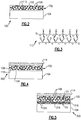
- Figure 2 schematically illustrates a representative portion of an example article 100 for the gas turbine engine 20 that includes a composite material 102 that is used as a barrier layer.
- the article 100 can be, for example, an airfoil in the compressor section 24 or turbine section 28, a combustor liner panel in the combustor section 26, a blade outer air seal, or other component that would benefit from the examples herein.
- the composite material 102 is used as an environmental barrier layer to protect an underlying substrate 104 from environmental conditions, as well as thermal conditions.
- the composite material 102 can be used as a stand-alone barrier layer, as an outermost/top coat with additional underlying layers, or in combination with other coating under- or over-layers, such as, but not limited to, ceramic-based topcoats.
- the composite material 102 includes a matrix of silicon dioxide (SiO 2 ) 106, a dispersion of "gettering” particles, and a dispersion of diffusive particles.
- the gettering particles are silicon oxycarbide particles (SiOC) 108 and the diffusive particles are barium-magnesium alumino-silicate particles 110 ("BMAS particles”), though other examples are contemplated.
- the gettering particles 108 could be, for instance, silicon oxycarbide (SiOC) particles, silicon carbide (SiC) particles, silicon nitride (Si 3 N 4 ) particles, silicon oxycarbonitride (SiOCN) particles, silicon aluminum oxynitride (SiAlON) particles, silicon boron oxycarbonitride (SiBOCN) particles, or combinations thereof.
- the diffusive particles 110 could be, for instance, BMAS particles, barium strontium aluminum silicate particles, magnesium silicate particles, alkaline earth aluminum silicate particles, yttrium aluminum silicate particles, ytterbium aluminum silicate particles, other rare earth metal aluminum silicate particles, or combinations thereof.
- the gettering particles 108 form a network within the matrix.
- silicon oxycarbide particles 108 have silicon, oxygen, and carbon in a covalently bonded network, as shown in the example network 112 in Figure 3 .
- the network 112 is amorphous and thus does not have long range crystalline structure.
- the illustrated network 112 is merely one example in which at least a portion of the silicon atoms are bonded to both O atoms and C atoms. As can be appreciated, the bonding of the network 112 will vary depending upon the atomic ratios of the Si, C, and O.
- the silicon oxycarbide particles 108 have a composition SiO x M z C y , where M is at least one metal, x ⁇ 2, y >0, z ⁇ 1, and x and z are non-zero.
- the metal can include aluminum, boron, transition metals, refractory metals, rare earth metals, alkaline earth metals or combinations thereof.
- the composite material 102 includes, by volume, 1-30% of the diffusive/BMAS particles 110. In a more particular example, the composite material 102 includes, by volume, 1 - 10% of diffusive particles. In a further example, the composite material 102 includes, by volume, 30-94% of the gettering particles 108. In a particular example, the composite material includes, by volume, 60-90% of the gettering particles 108. In one further example, the composite material 102 includes, by volume, 5-40% of the matrix 26 of silicon dioxide. In a further example, the composite material 102 includes, by volume, 1-30% of the diffusive particles 110, 5-40% of the matrix 106 of silicon dioxide, and a balance of the gettering particles 108.
- the barrier layer protects the underlying substrate 104 from oxygen and moisture.
- the substrate 104 can be a ceramic-based substrate, such as a silicon-containing ceramic material.
- silicon carbide is another non-limiting example is silicon carbide fibers in a silicon carbide matrix.
- the gettering particles 108 and the diffusive particles 110 of the barrier layer function as an oxygen and moisture diffusion barrier to limit the exposure of the underlying substrate 104 to oxygen and/or moisture from the surrounding environment.
- the diffusive particles 110 such as BMAS particles 110, enhance oxidation and moisture protection by diffusing to the outer surface of the barrier layer opposite of the substrate 104 and forming a sealing layer that seals the underlying substrate 104 from oxygen/moisture exposure.
- cationic metal species of the diffusive particles 110 can diffuse into the gettering particles 108 to enhance oxidation stability of the gettering material.
- the diffusion behavior of the diffusive particles 110 may operate to seal any microcracks that could form in the barrier layer. Sealing the micro-cracks could prevent oxygen from infiltrating the barrier layer, which further enhances the oxidation resistance of the barrier layer.
- the gettering particles, such as the gettering particles 108 can react with oxidant species, such as oxygen or water that could diffuse into the barrier layer. In this way, the gettering particles could reduce the likelihood of those oxidant species reaching and oxidizing the substrate 104.
- the effectiveness of the gettering particles 108 in providing oxidation resistance is related to the surface area of the particles.
- the greater the surface area of the particles 108 the more likely the individual particles 108 will encounter and react with oxidant species. Further, such reaction causes a consumption of the gettering material and corresponding buildup of oxide scale on the surface of the particles 108, reducing the effective surface area of the particles 108.
- the greater the surface area of the particles 108 the more surface area available for reacting with oxidant species, which reduces the likelihood that oxidant species will reach and oxidize the substrate 104.
- particles 108 with higher surface area generally improve the effectiveness and longevity of the oxidation resistance of the barrier layer.
- practical and processing constraints limit the size of particles 108. If the particles 108 are too large, application of the barrier layer (especially by spray coating, discussed in more detail below) becomes difficult. Also, if the particles 108 are too large, the packing effectiveness of the particles 108 relative to one another within the barrier layer is decreased, meaning in some areas there may be relatively large distances between adjacent particles 108. In those areas, there may be reduced localized oxidation resistance.
- the effective surface area of the particles 108 is related to the dimension of the particles 108 and their shape.
- effective surface area of the particles 108 can be determined by determining one or more dimensions 108 of the particles by any known imaging technique and calculating the surface area of the particles 108 according to a known relationship between the dimensions and the shape.
- an average effective surface area of the particles 108 within the barrier layer can be approximated based on an average dimension of the particles 108 within the barrier layer.
- the particles 108 are approximately spherical in shape, e.g., they have an aspect ratio that is close to one (1:1 ratio).
- other shapes such as elongated shapes with aspect ratios less than one, are also contemplated.
- the particles 108 can be defined by an average maximum dimension of the particles 108.
- the average maximum dimension corresponds to the diameter of the particles 108, represented by D1 in Figure 5 .
- the particles 108 have an average maximum dimension of between about 30-70 microns.
- any given sample of particles 108 contains particles 108 of different sizes.
- 65% ⁇ 5% by volume of the particles 108 have a maximum dimension D1 of between about 30-70 microns.
- the modal particle (which is sometimes known as d50) has D1 of about 55 microns, and 10% of the volume of the particles have D1 within about 5% of the modal particle D1 (i.e.
- the particles 108 have an average maximum dimension of between about 30-70 microns and individual particles 108 have maximum dimensions that range from about 1-100 microns. In another example, the particles 108 have an average maximum dimension of between about 40-60 microns. In a further example, the particles 108 have an average maximum dimension of between about 40-60 microns and individual particles 108 have maximum dimensions that range from about 5-75 microns.
- the average maximum dimension of the particles 108 is related to the average effective surface area of the particles 108 in the barrier layer.
- a total effective surface area for the particles 108 in the barrier layer is related to the amount of particles 108 in the barrier layer (e.g., vol % of particles 108 in the composite material 102) and the thickness of the barrier layer.
- the more particles 108 in the barrier layer e.g., the higher the vol. % of particles 108 in the composite material 102, the thicker the barrier layer, or both
- the total effective surface area for the particles 108 in the barrier layer is between about 12,000 and 564,000 cm 2 per centimeter of barrier layer thickness.
- the total effective surface area for the particles 108 is between about 25,700 to 90,000 cm 2 per centimeter of barrier layer thickness. In a further example, the total effective surface area for the particles 108 is between about 30,000 to 67,500 cm 2 per centimeter of barrier layer thickness. In one example, an average maximum dimension of the BMAS particles 110 is less than the average maximum dimension of the silicon oxycarbide particles 108.
- Figure 4 shows another example article 200 that includes the composite material 102 as a barrier layer arranged on the substrate 104.
- the article 200 additionally includes a ceramic-based top coat 114 interfaced with the barrier layer.
- the ceramic-based top coat 114 can include one or more layers of an oxide-based material.
- the oxide-based material can be, for instance, hafnium-based oxides, (such as hafnia, hafnium silicate), yttrium-based oxides (such as yttrium silicate, yttria stabilized zirconia), or gadolinia stabilized zirconia, or combinations thereof, but is not limited to such oxides.
- Figure 5 illustrates another example article 300 that is somewhat similar to the article 200 shown in Figure 4 but includes a distinct intermediate layer 316 interposed between the barrier layer of the composite material 102 and the substrate 104.
- the distinct intermediate layer 316 includes an intermediate layer matrix 318 of silicon dioxide and a dispersion of intermediate layer silicon oxycarbide particles 320 in the intermediate layer matrix 318.
- the intermediate layer silicon oxycarbide particles 320 are similar to the silicon oxycarbide particles 108 in the composition but, in this example, the intermediate layer silicon oxycarbide particles 320 have an average maximum dimension (D2) that is less than the average maximum dimension (D1) of the silicon oxycarbide particles 108.
- the relatively small intermediate layer silicon oxycarbide particles 320 provide a relatively low roughness for enhanced bonding with the underlying substrate 104.
- the larger silicon oxycarbide particles 108 of the barrier layer provide enhanced blocking of oxygen/moisture diffusion.
- the barrier layer and intermediate layer 316 provide good adhesion and good oxidation/moisture resistance.
- D1 is 44-75 micrometers and D2 is 1-44 micrometers.
- the intermediate layer 316 can include, by volume, 5-40% of the intermediate layer matrix 318 of silicon dioxide and a balance of the intermediate layer silicon oxycarbide particles 320.
- a portion of the BMAS particles 110 from the barrier layer can penetrate or diffuse into the intermediate layer 316, during processing, during operation at high temperatures, or both.
- a seal coat layer of SiO 2 with or without BMAS particles, can be provided between the barrier layer and the intermediate layer 316 to provide adhesion and additional sealing.
- said compositions can include only the listed constituents.
- the matrix 106 and 318 can be continuous. The two-layer structure can also demonstrate good oxidation protection at 2000-2700°F for 500 hours or longer as well as good adhesion with the ceramic-based top coat 114.
- the barrier layer and/or intermediate layer 316 can be fabricated using a slurry coating method.
- the appropriate slurries can be prepared by mixing components, such as silicon oxycarbide, barium-magnesium alumino-silicate, and powder of silicon dioxide or colloidal silica (Ludox) in a carrier fluid, such as water.
- the slurries can be mixed by agitation or ball milling and the resulting slurry can be painted, dipped, sprayed or otherwise deposited onto the underlying substrate 104.
- the slurry can then be dried at room temperature or at an elevated temperature to remove the carrier fluid. In one example, the slurry is dried and cured at about 100-300°C for about 5 - 60 minutes.
- the green coating can then be sintered at an elevated temperature in air for a selected amount of time.
- the sintering includes heating at 1500°C or greater in an air environment for at least 1 hour.
- the composite material 102 can be prepared using a slurry coating method.
- Slurries can be prepared by mixing components such as SiOC, BMAS, SiO 2 or Ludox (a source colloidal SiO 2 ) and water using agitation or ball milling.
- Various slurry coating methods such as painting, dipping and spraying can be used to coat ceramic matrix composite (CMC) substrates. Coatings formed from slurry are dried at room temperature and cured at 300°C for about 5 - 60 minutes. During the heating, cross-linking of the colloidal silica occurs. This coating process can be repeated until all layers are coated. The bond coat is finally sintered at 1500°C in air for at least 1 hour.
- a slurry of SiOC/SiO 2 75/25 vol% was prepared by mixing appropriate amounts of SiOC and Ludox colloidal silica. A small amount of water was added to adjust the viscosity. The slurry was further mixed by ball milling for at least 15 hours. A slurry of SiOC/BMAS/SiO 2 80/5/15 vol% was prepared likewise by mixing appropriate amounts of SiOC, BMAS and Ludox colloidal silica and ball milling for more than 15 hours.
- An inner layer was applied on a cleaned CMC substrate 104 by painting. The coating was then dried at room temperature for about 5 - 60 minutes and heated in an oven at between about 100 - 300°C for about 5 - 60 minutes. During the heating, cross-linking of the colloidal silica occurs.
- An outer layer was applied in the same fashion as the inner layer with the exception that the outer layer was applied with two passes. In between the two passes, in one example, the specimen is submerged in Ludox colloidal silica solution, air dried at room temperature and heat treated at between about 100 - 300°C for about 5 - 60 minutes to provide a silica sealing layer. After completion of the two layer bond coat, the specimen was sintered at 1500°C for at least 1 hour.
Landscapes
- Chemical & Material Sciences (AREA)
- Engineering & Computer Science (AREA)
- Ceramic Engineering (AREA)
- Materials Engineering (AREA)
- Structural Engineering (AREA)
- Organic Chemistry (AREA)
- Inorganic Chemistry (AREA)
- Mechanical Engineering (AREA)
- General Engineering & Computer Science (AREA)
- Dispersion Chemistry (AREA)
- Chemical Kinetics & Catalysis (AREA)
- Manufacturing & Machinery (AREA)
- Laminated Bodies (AREA)
Abstract
Description
- A gas turbine engine typically includes a fan section, a compressor section, a combustor section and a turbine section. Air entering the compressor section is compressed and delivered into the combustion section where it is mixed with fuel and ignited to generate a high-energy exhaust gas flow. The high-energy exhaust gas flow expands through the turbine section to drive the compressor and the fan section. The compressor section typically includes low and high pressure compressors, and the turbine section includes low and high pressure turbines.
- This disclosure relates to composite articles, such as those used in gas turbine engines. Components, such as gas turbine engine components, may be subjected to high temperatures, corrosive and oxidative conditions, and elevated stress levels. In order to improve the thermal and/or oxidative stability, the component may include a protective barrier coating.
- An article according to an exemplary embodiment of this disclosure, among other possible things includes a ceramic-based substrate and a barrier layer on the ceramic-based substrate. The barrier layer includes a matrix phase and a network of gettering particles in the matrix phase. The gettering particles have an average maximum dimension between about 30 and 70 microns. The gettering particles have maximum dimensions that range from about 1 to 100 microns. The barrier layer also includes a dispersion of diffusive particles in the matrix phase.
- In a further example of the foregoing, the barrier layer includes, by volume, 30-94% of the gettering particles.
- In a further example of any of the foregoing, the barrier layer includes, by volume, 60-90% of the gettering particles.
- In a further example of any of the foregoing, the barrier layer includes, by volume, 1-30% of the diffusive particles, 5-40% of the matrix of SiO2, and a balance of the gettering particles.
- In a further example of any of the foregoing, the diffusive particles have an average maximum dimension that is smaller than the average maximum dimension of the gettering particles.
- In a further example of any of the foregoing, the gettering particles have an average maximum dimension that is between about 40 and 60 microns.
- In a further example of any of the foregoing, the gettering particles have maximum dimensions between about 5-75 microns.
- In a further example of any of the foregoing, the gettering particles are spherical.
- In a further example of any of the foregoing, the gettering particles are reactive with respect to oxidant species.
- In a further example of any of the foregoing, the gettering particles include at least one of silicon oxycarbide (SiOC) particles, silicon carbide (SiC) particles, silicon nitride (Si3N4) particles, silicon oxycarbonitride (SiOCN) particles, silicon aluminum oxynitride (SiAlON) particles, and silicon boron oxycarbonitride (SiBOCN) particles.
- In a further example of any of the foregoing, the diffusive particles include at least one of barium magnesium aluminum silicate (BMAS), barium strontium aluminum silicate, magnesium silicate, alkaline earth aluminum silicate, yttrium aluminum silicate, ytterbium aluminum silicate, and rare earth metal aluminum silicate particles.
- In a further example of any of the foregoing, the article further comprises a distinct intermediate layer between the barrier layer and the ceramic-based substrate, the distinct intermediate layer including an intermediate layer matrix of SiO2 and a dispersion of intermediate layer gettering particles in the intermediate layer matrix.
- In a further example of any of the foregoing, the gettering particles are silicon oxycarbide particles that have a composition SiOxMzCy, where M is at least one metal, x < 2, y > 0 and z < 1 and x and z are non-zero, and the diffusive particles are preferably barium magnesium aluminum silicate particles.
- In a further example of any of the foregoing, the article includes a ceramic-based top coat on the barrier layer.
- A composite material according to an exemplary embodiment of this disclosure, among other possible things includes a matrix of SiO2 and a dispersion of silicon oxycarbide particles in the matrix. The silicon oxycarbide particles have Si, O, and C in a covalently bonded network. The silicon oxycarbide particles have an average maximum dimension between about 30 and 70 microns. The silicon oxycarbide particles have maximum dimensions that range from about 1 to 100 microns. The composite material also includes a dispersion of barium-magnesium alumino-silicate particles in the matrix.
- In a further example of the foregoing, the silicon oxycarbide particles have an average maximum dimension that is between about 40 and 60 microns.
- In a further example of any of the foregoing, the silicon oxycarbide particles are approximately spherical.
- In a further example of any of the foregoing, the silicon oxycarbide particles are reactive with respect to oxidant species.
- A method of applying a barrier layer to a substrate (for example, the substrate comprised in the article as herein described) according to an exemplary embodiment of this disclosure, among other possible things includes mixing particles of barium-magnesium alumino-silicate, particles of SiO2, and particles of silicon oxycarbide in a carrier fluid to form a slurry. The silicon oxycarbide particles have an average maximum dimension between about 30 and 70 microns. The silicon oxycarbide particles have maximum dimensions that range from about 1 to 100 microns. The method includes applying the slurry to a substrate, drying the slurry, and curing the slurry such that cross-linking occurs in the composite material.
- In a further example of the foregoing, the application is by spraying.
-
-
Figure 1 is a schematic view of an example gas turbine engine. -
Figure 2 illustrates an example article having a barrier layer of a composite material that includes barium-magnesium alumino-silicate particles. -
Figure 3 illustrates a network of silicon oxycarbide. -
Figure 4 illustrates another example article having a barrier layer of a composite material that includes barium-magnesium alumino-silicate particles. -
Figure 5 illustrates another example article having a barrier layer of a composite material that includes barium-magnesium alumino-silicate particles. -
Figure 1 schematically illustrates agas turbine engine 20. Thegas turbine engine 20 is disclosed herein as a two-spool turbofan that generally incorporates afan section 22, acompressor section 24, a combustor section 26 and aturbine section 28. Thefan section 22 drives air along a bypass flow path B in a bypass duct defined within ahousing 15 such as a fan case or nacelle, and also drives air along a core flow path C for compression and communication into the combustor section 26 then expansion through theturbine section 28. Although depicted as a two-spool turbofan gas turbine engine in the disclosed non-limiting embodiment, it should be understood that the concepts described herein are not limited to use with two-spool turbofans as the teachings may be applied to other types of turbine engines including three-spool architectures. - The
exemplary engine 20 generally includes alow speed spool 30 and ahigh speed spool 32 mounted for rotation about an engine central longitudinal axis A relative to an enginestatic structure 36 viaseveral bearing systems 38. It should be understood thatvarious bearing systems 38 at various locations may alternatively or additionally be provided, and the location ofbearing systems 38 may be varied as appropriate to the application. - The
low speed spool 30 generally includes aninner shaft 40 that interconnects a first (or low) pressure compressor 44 and a first (or low)pressure turbine 46. Theinner shaft 40 is connected to thefan 42 through a speed change mechanism, which in exemplarygas turbine engine 20 is illustrated as a gearedarchitecture 48 to drive afan 42 at a lower speed than thelow speed spool 30. Thehigh speed spool 32 includes anouter shaft 50 that interconnects a second (or high)pressure compressor 52 and a second (or high)pressure turbine 54. Acombustor 56 is arranged inexemplary gas turbine 20 between thehigh pressure compressor 52 and thehigh pressure turbine 54. Amid-turbine frame 57 of the enginestatic structure 36 may be arranged generally between thehigh pressure turbine 54 and thelow pressure turbine 46. Themid-turbine frame 57 further supports bearingsystems 38 in theturbine section 28. Theinner shaft 40 and theouter shaft 50 are concentric and rotate viabearing systems 38 about the engine central longitudinal axis A which is collinear with their longitudinal axes. - The core airflow is compressed by the low pressure compressor 44 then the
high pressure compressor 52, mixed and burned with fuel in thecombustor 56, then expanded through thehigh pressure turbine 54 andlow pressure turbine 46. Themid-turbine frame 57 includesairfoils 59 which are in the core airflow path C. Theturbines low speed spool 30 andhigh speed spool 32 in response to the expansion. It will be appreciated that each of the positions of thefan section 22,compressor section 24, combustor section 26,turbine section 28, and fandrive gear system 48 may be varied. For example,gear system 48 may be located aft of the low pressure compressor, or aft of the combustor section 26 or even aft ofturbine section 28, andfan 42 may be positioned forward or aft of the location ofgear system 48. - The
engine 20 in one example is a high-bypass geared aircraft engine. In a further example, theengine 20 bypass ratio is greater than about six (6), with an example embodiment being greater than about ten (10), the gearedarchitecture 48 is an epicyclic gear train, such as a planetary gear system or other gear system, with a gear reduction ratio of greater than about 2.3 and thelow pressure turbine 46 has a pressure ratio that is greater than about five. In one disclosed embodiment, theengine 20 bypass ratio is greater than about ten (10:1), the fan diameter is significantly larger than that of the low pressure compressor 44, and thelow pressure turbine 46 has a pressure ratio that is greater than about five 5:1.Low pressure turbine 46 pressure ratio is pressure measured prior to inlet oflow pressure turbine 46 as related to the pressure at the outlet of thelow pressure turbine 46 prior to an exhaust nozzle. The gearedarchitecture 48 may be an epicycle gear train, such as a planetary gear system or other gear system, with a gear reduction ratio of greater than about 2.3:1 and less than about 5:1. It should be understood, however, that the above parameters are only exemplary of one embodiment of a geared architecture engine and that the present invention is applicable to other gas turbine engines including direct drive turbofans. A significant amount of thrust is provided by the bypass flow B due to the high bypass ratio. Thefan section 22 of theengine 20 is designed for a particular flight condition - typically cruise at about 0.8 Mach and about 35,000 feet (10,668 meters). The flight condition of 0.8 Mach and 35,000 ft (10,668 meters), with the engine at its best fuel consumption - also known as "bucket cruise Thrust Specific Fuel Consumption ('TSFC')" - is the industry standard parameter of lbm of fuel being burned divided by lbf of thrust the engine produces at that minimum point. "Low fan pressure ratio" is the pressure ratio across the fan blade alone, without a Fan Exit Guide Vane ("FEGV") system. The low fan pressure ratio as disclosed herein according to one non-limiting embodiment is less than about 1.45. "Low corrected fan tip speed" is the actual fan tip speed in ft/sec divided by an industry standard temperature correction of [(Tram °R) / (518.7 °R)]0.5. The "Low corrected fan tip speed" as disclosed herein according to one non-limiting embodiment is less than about 1150 ft / second (350.5 meters/second). - The example gas turbine engine includes the
fan section 22 that comprises in one non-limiting embodiment less than about 26 fan blades. In another non-limiting embodiment, thefan section 22 includes less than about 20 fan blades. Moreover, in one disclosed embodiment thelow pressure turbine 46 includes no more than about 6 turbine rotors. In another non-limiting example embodiment thelow pressure turbine 46 includes about 3 turbine rotors. A ratio between the number of fan blades and the number of low pressure turbine rotors is between about 3.3 and about 8.6. The examplelow pressure turbine 46 provides the driving power to rotate thefan section 22 and therefore the relationship between the number of turbine rotors in thelow pressure turbine 46 and the number of blades in thefan section 22 disclose an examplegas turbine engine 20 with increased power transfer efficiency. -
Figure 2 schematically illustrates a representative portion of anexample article 100 for thegas turbine engine 20 that includes acomposite material 102 that is used as a barrier layer. Thearticle 100 can be, for example, an airfoil in thecompressor section 24 orturbine section 28, a combustor liner panel in the combustor section 26, a blade outer air seal, or other component that would benefit from the examples herein. In this example, thecomposite material 102 is used as an environmental barrier layer to protect anunderlying substrate 104 from environmental conditions, as well as thermal conditions. As will be appreciated, thecomposite material 102 can be used as a stand-alone barrier layer, as an outermost/top coat with additional underlying layers, or in combination with other coating under- or over-layers, such as, but not limited to, ceramic-based topcoats. - The
composite material 102 includes a matrix of silicon dioxide (SiO2) 106, a dispersion of "gettering" particles, and a dispersion of diffusive particles. In one example, the gettering particles are silicon oxycarbide particles (SiOC) 108 and the diffusive particles are barium-magnesium alumino-silicate particles 110 ("BMAS particles"), though other examples are contemplated. Thegettering particles 108 could be, for instance, silicon oxycarbide (SiOC) particles, silicon carbide (SiC) particles, silicon nitride (Si3N4) particles, silicon oxycarbonitride (SiOCN) particles, silicon aluminum oxynitride (SiAlON) particles, silicon boron oxycarbonitride (SiBOCN) particles, or combinations thereof. Thediffusive particles 110 could be, for instance, BMAS particles, barium strontium aluminum silicate particles, magnesium silicate particles, alkaline earth aluminum silicate particles, yttrium aluminum silicate particles, ytterbium aluminum silicate particles, other rare earth metal aluminum silicate particles, or combinations thereof. - The
gettering particles 108 form a network within the matrix. For instance,silicon oxycarbide particles 108 have silicon, oxygen, and carbon in a covalently bonded network, as shown in theexample network 112 inFigure 3 . - The
network 112 is amorphous and thus does not have long range crystalline structure. The illustratednetwork 112 is merely one example in which at least a portion of the silicon atoms are bonded to both O atoms and C atoms. As can be appreciated, the bonding of thenetwork 112 will vary depending upon the atomic ratios of the Si, C, and O. In one example, thesilicon oxycarbide particles 108 have a composition SiOxMzCy, where M is at least one metal, x <2, y >0, z <1, and x and z are non-zero. The metal can include aluminum, boron, transition metals, refractory metals, rare earth metals, alkaline earth metals or combinations thereof. - In one example, the
composite material 102 includes, by volume, 1-30% of the diffusive/BMAS particles 110. In a more particular example, thecomposite material 102 includes, by volume, 1 - 10% of diffusive particles. In a further example, thecomposite material 102 includes, by volume, 30-94% of thegettering particles 108. In a particular example, the composite material includes, by volume, 60-90% of thegettering particles 108. In one further example, thecomposite material 102 includes, by volume, 5-40% of the matrix 26 of silicon dioxide. In a further example, thecomposite material 102 includes, by volume, 1-30% of thediffusive particles 110, 5-40% of thematrix 106 of silicon dioxide, and a balance of thegettering particles 108. - The barrier layer protects the
underlying substrate 104 from oxygen and moisture. For example, thesubstrate 104 can be a ceramic-based substrate, such as a silicon-containing ceramic material. One example is silicon carbide. Another non-limiting example is silicon carbide fibers in a silicon carbide matrix. Thegettering particles 108 and thediffusive particles 110 of the barrier layer function as an oxygen and moisture diffusion barrier to limit the exposure of theunderlying substrate 104 to oxygen and/or moisture from the surrounding environment. Without being bound by any particular theory, thediffusive particles 110, such asBMAS particles 110, enhance oxidation and moisture protection by diffusing to the outer surface of the barrier layer opposite of thesubstrate 104 and forming a sealing layer that seals theunderlying substrate 104 from oxygen/moisture exposure. Additionally, cationic metal species of the diffusive particles 110 (for instance, for BMAS particles, barium, magnesium, and aluminum) can diffuse into thegettering particles 108 to enhance oxidation stability of the gettering material. Further, the diffusion behavior of thediffusive particles 110 may operate to seal any microcracks that could form in the barrier layer. Sealing the micro-cracks could prevent oxygen from infiltrating the barrier layer, which further enhances the oxidation resistance of the barrier layer. The gettering particles, such as thegettering particles 108, can react with oxidant species, such as oxygen or water that could diffuse into the barrier layer. In this way, the gettering particles could reduce the likelihood of those oxidant species reaching and oxidizing thesubstrate 104. - It has been discovered that the effectiveness of the
gettering particles 108, such as thesilicon oxycarbide particles 108, in providing oxidation resistance is related to the surface area of the particles. In general, the greater the surface area of theparticles 108, the more likely theindividual particles 108 will encounter and react with oxidant species. Further, such reaction causes a consumption of the gettering material and corresponding buildup of oxide scale on the surface of theparticles 108, reducing the effective surface area of theparticles 108. Thus, the greater the surface area of theparticles 108, the more surface area available for reacting with oxidant species, which reduces the likelihood that oxidant species will reach and oxidize thesubstrate 104. Accordingly,particles 108 with higher surface area generally improve the effectiveness and longevity of the oxidation resistance of the barrier layer. However, practical and processing constraints limit the size ofparticles 108. If theparticles 108 are too large, application of the barrier layer (especially by spray coating, discussed in more detail below) becomes difficult. Also, if theparticles 108 are too large, the packing effectiveness of theparticles 108 relative to one another within the barrier layer is decreased, meaning in some areas there may be relatively large distances betweenadjacent particles 108. In those areas, there may be reduced localized oxidation resistance. - The effective surface area of the
particles 108 is related to the dimension of theparticles 108 and their shape. In one example, effective surface area of theparticles 108 can be determined by determining one ormore dimensions 108 of the particles by any known imaging technique and calculating the surface area of theparticles 108 according to a known relationship between the dimensions and the shape. Furthermore, an average effective surface area of theparticles 108 within the barrier layer can be approximated based on an average dimension of theparticles 108 within the barrier layer. - In one example, the
particles 108 are approximately spherical in shape, e.g., they have an aspect ratio that is close to one (1:1 ratio). However, other shapes, such as elongated shapes with aspect ratios less than one, are also contemplated. - The
particles 108 can be defined by an average maximum dimension of theparticles 108. In the example where theparticles 108 are approximately spherical, the average maximum dimension corresponds to the diameter of theparticles 108, represented by D1 inFigure 5 . In one example, theparticles 108 have an average maximum dimension of between about 30-70 microns. Still, any given sample ofparticles 108 containsparticles 108 of different sizes. In a particular example, 65% ±5% by volume of theparticles 108 have a maximum dimension D1 of between about 30-70 microns. In one example, the modal particle (which is sometimes known as d50) has D1 of about 55 microns, and 10% of the volume of the particles have D1 within about 5% of the modal particle D1 (i.e. D1 ranging between 52.25 and 57.75 microns) and 72% of the volume of the particles having D1 within 50% of the modal particle D1 (i.e. D1 ranging between 27.5 and 82.5 microns). For instance, in one example, theparticles 108 have an average maximum dimension of between about 30-70 microns andindividual particles 108 have maximum dimensions that range from about 1-100 microns. In another example, theparticles 108 have an average maximum dimension of between about 40-60 microns. In a further example, theparticles 108 have an average maximum dimension of between about 40-60 microns andindividual particles 108 have maximum dimensions that range from about 5-75 microns. - As discussed above, the average maximum dimension of the
particles 108 is related to the average effective surface area of theparticles 108 in the barrier layer. In turn, a total effective surface area for theparticles 108 in the barrier layer is related to the amount ofparticles 108 in the barrier layer (e.g., vol % ofparticles 108 in the composite material 102) and the thickness of the barrier layer. Generally, themore particles 108 in the barrier layer (e.g., the higher the vol. % ofparticles 108 in thecomposite material 102, the thicker the barrier layer, or both), the higher the total effective surface area for theparticles 108 in the barrier layer. For an example barrier layer, the total effective surface area for theparticles 108 is between about 12,000 and 564,000 cm2 per centimeter of barrier layer thickness. In a further example, the total effective surface area for theparticles 108 is between about 25,700 to 90,000 cm2 per centimeter of barrier layer thickness. In a further example, the total effective surface area for theparticles 108 is between about 30,000 to 67,500 cm2 per centimeter of barrier layer thickness. In one example, an average maximum dimension of theBMAS particles 110 is less than the average maximum dimension of thesilicon oxycarbide particles 108. -
Figure 4 shows anotherexample article 200 that includes thecomposite material 102 as a barrier layer arranged on thesubstrate 104. In this example, thearticle 200 additionally includes a ceramic-basedtop coat 114 interfaced with the barrier layer. As an example, the ceramic-basedtop coat 114 can include one or more layers of an oxide-based material. The oxide-based material can be, for instance, hafnium-based oxides, (such as hafnia, hafnium silicate), yttrium-based oxides (such as yttrium silicate, yttria stabilized zirconia), or gadolinia stabilized zirconia, or combinations thereof, but is not limited to such oxides. -
Figure 5 illustrates anotherexample article 300 that is somewhat similar to thearticle 200 shown inFigure 4 but includes a distinctintermediate layer 316 interposed between the barrier layer of thecomposite material 102 and thesubstrate 104. In this example, the distinctintermediate layer 316 includes anintermediate layer matrix 318 of silicon dioxide and a dispersion of intermediate layersilicon oxycarbide particles 320 in theintermediate layer matrix 318. The intermediate layersilicon oxycarbide particles 320 are similar to thesilicon oxycarbide particles 108 in the composition but, in this example, the intermediate layersilicon oxycarbide particles 320 have an average maximum dimension (D2) that is less than the average maximum dimension (D1) of thesilicon oxycarbide particles 108. The relatively small intermediate layersilicon oxycarbide particles 320 provide a relatively low roughness for enhanced bonding with theunderlying substrate 104. The largersilicon oxycarbide particles 108 of the barrier layer provide enhanced blocking of oxygen/moisture diffusion. Thus, in combination, the barrier layer andintermediate layer 316 provide good adhesion and good oxidation/moisture resistance. In one further example, D1 is 44-75 micrometers and D2 is 1-44 micrometers. - In one example, the
intermediate layer 316 can include, by volume, 5-40% of theintermediate layer matrix 318 of silicon dioxide and a balance of the intermediate layersilicon oxycarbide particles 320. In further examples, a portion of theBMAS particles 110 from the barrier layer can penetrate or diffuse into theintermediate layer 316, during processing, during operation at high temperatures, or both. In a further example, a seal coat layer of SiO2, with or without BMAS particles, can be provided between the barrier layer and theintermediate layer 316 to provide adhesion and additional sealing. In further examples of any of the compositions disclosed herein, said compositions can include only the listed constituents. Additionally, in any of the examples disclosed herein, thematrix top coat 114. - The barrier layer and/or
intermediate layer 316 can be fabricated using a slurry coating method. The appropriate slurries can be prepared by mixing components, such as silicon oxycarbide, barium-magnesium alumino-silicate, and powder of silicon dioxide or colloidal silica (Ludox) in a carrier fluid, such as water. The slurries can be mixed by agitation or ball milling and the resulting slurry can be painted, dipped, sprayed or otherwise deposited onto theunderlying substrate 104. The slurry can then be dried at room temperature or at an elevated temperature to remove the carrier fluid. In one example, the slurry is dried and cured at about 100-300°C for about 5 - 60 minutes. During the heating, cross-linking of the colloidal silica occurs. The green coating can then be sintered at an elevated temperature in air for a selected amount of time. In one example, the sintering includes heating at 1500°C or greater in an air environment for at least 1 hour. - The
composite material 102 can be prepared using a slurry coating method. Slurries can be prepared by mixing components such as SiOC, BMAS, SiO2 or Ludox (a source colloidal SiO2) and water using agitation or ball milling. Various slurry coating methods such as painting, dipping and spraying can be used to coat ceramic matrix composite (CMC) substrates. Coatings formed from slurry are dried at room temperature and cured at 300°C for about 5 - 60 minutes. During the heating, cross-linking of the colloidal silica occurs. This coating process can be repeated until all layers are coated. The bond coat is finally sintered at 1500°C in air for at least 1 hour. - In one further example, a slurry of SiOC/SiO2 75/25 vol% was prepared by mixing appropriate amounts of SiOC and Ludox colloidal silica. A small amount of water was added to adjust the viscosity. The slurry was further mixed by ball milling for at least 15 hours. A slurry of SiOC/BMAS/SiO2 80/5/15 vol% was prepared likewise by mixing appropriate amounts of SiOC, BMAS and Ludox colloidal silica and ball milling for more than 15 hours.
- An inner layer was applied on a cleaned
CMC substrate 104 by painting. The coating was then dried at room temperature for about 5 - 60 minutes and heated in an oven at between about 100 - 300°C for about 5 - 60 minutes. During the heating, cross-linking of the colloidal silica occurs. An outer layer was applied in the same fashion as the inner layer with the exception that the outer layer was applied with two passes. In between the two passes, in one example, the specimen is submerged in Ludox colloidal silica solution, air dried at room temperature and heat treated at between about 100 - 300°C for about 5 - 60 minutes to provide a silica sealing layer. After completion of the two layer bond coat, the specimen was sintered at 1500°C for at least 1 hour. - Although the different examples are illustrated as having specific components, the examples of this disclosure are not limited to those particular combinations. It is possible to use some of the components or features from any of the embodiments in combination with features or components from any of the other embodiments.
- Certain embodiments of the present disclosure are as follows:
- 1. An article comprising:
- a ceramic-based substrate; and
- a barrier layer on the ceramic-based substrate, the barrier layer including:
- a matrix phase,
- a network of gettering particles in the matrix phase, wherein the gettering particles have an average maximum dimension between about 30 and 70 microns, wherein the gettering particles have maximum dimensions that range from about 1 to 100 microns, and
- a dispersion of diffusive particles in the matrix phase.
- 2. The article as recited in embodiment 1, wherein the barrier layer includes, by volume, 30-94% of the gettering particles.
- 3. The article as recited in embodiment 2, wherein the barrier layer includes, by volume, 60-90% of the gettering particles.
- 4. The article as recited in embodiment 1, wherein the barrier layer includes, by volume, 1-30% of the diffusive particles, 5-40% of the matrix of SiO2, and a balance of the gettering particles.
- 5. The article as recited in embodiment 1, wherein the diffusive particles have an average maximum dimension that is smaller than the average maximum dimension of the gettering particles.
- 6. The article as recited in embodiment 1, wherein the gettering particles have an average maximum dimension that is between about 40 and 60 microns.
- 7. The article as recited in embodiment 6, wherein the gettering particles have dimensions between about 5-75 microns.
- 8. The article as recited in embodiment 1, wherein the gettering particles are spherical.
- 9. The article as recited in embodiment 1, wherein the gettering particles are reactive with respect to oxidant species.
- 10. The article as recited in embodiment 1, wherein the gettering particles include at least one of silicon oxycarbide (SiOC) particles, silicon carbide (SiC) particles, silicon nitride (Si3N4), silicon oxycarbonitride (SiOCN) particles, silicon aluminum oxynitride (SiAlON) particles, and silicon boron oxycarbonitride (SiBOCN) particles.
- 11. The article as recited in embodiment 1, wherein the diffusive particles include at least one of barium magnesium aluminum silicate (BMAS), barium strontium aluminum silicate, magnesium silicate, alkaline earth aluminum silicate, yttrium aluminum silicate, ytterbium aluminum silicate, and rare earth metal aluminum silicate particles.
- 12. The article as recited in embodiment 1, further comprising a distinct intermediate layer between the barrier layer and the ceramic-based substrate, the distinct intermediate layer including an intermediate layer matrix of SiO2 and a dispersion of intermediate layer gettering particles in the intermediate layer matrix.
- 13. The article as recited in embodiment 1, wherein the gettering particles are silicon oxycarbide particles that have a composition SiOxMzCy, where M is at least one metal, x < 2, y > 0 and z < 1 and x and z are non-zero, and wherein the diffusive particles are barium magnesium aluminum silicate particles.
- 14. The article as recited in embodiment 1, further comprising a ceramic-based top coat on the barrier layer.
- 15. A composite material comprising:
- a matrix of SiO2;
- a dispersion of silicon oxycarbide particles in the matrix, the silicon oxycarbide particles having Si, O, and C in a covalently bonded network, wherein the silicon oxycarbide particles have an average maximum dimension between about 30 and 70 microns, wherein the silicon oxycarbide particles have maximum dimensions that range from about 1 to 100 microns; and
- a dispersion of barium-magnesium alumino-silicate particles in the matrix.
- 16. The composite material as recited in
embodiment 15, wherein the silicon oxycarbide particles have an average maximum dimension that is between about 40 and 60 microns. - 17. The composite material as recited in
embodiment 15, wherein the silicon oxycarbide particles are approximately spherical. - 18. The composite material as recited in
embodiment 15, wherein the silicon oxycarbide particles are reactive with respect to oxidant species. - 19. A method of applying a barrier layer to a substrate, comprising:
- mixing particles of barium-magnesium alumino-silicate, particles of SiO2, and particles of silicon oxycarbide in a carrier fluid to form a slurry, wherein the silicon oxycarbide particles have an average maximum dimension between about 30 and 70 microns, wherein the silicon oxycarbide particles have maximum dimensions that range from about 1 to 100 microns;
- applying the slurry to a substrate;
- drying the slurry; and
- curing the slurry such that cross-linking occurs in the composite material.
- 20. The method of embodiment 19, wherein the applying is by spraying.
- The foregoing description shall be interpreted as illustrative and not in any limiting sense. A worker of ordinary skill in the art would understand that certain modifications could come within the scope of this disclosure. For these reasons, the following claims should be studied to determine the true scope and content of this disclosure.
Claims (15)
- An article comprising:a ceramic-based substrate; anda barrier layer on the ceramic-based substrate, the barrier layer including:a matrix phase,a network of gettering particles in the matrix phase, wherein the gettering particles have an average maximum dimension between about 30 and 70 microns, wherein the gettering particles have maximum dimensions that range from about 1 to 100 microns, anda dispersion of diffusive particles in the matrix phase.
- The article as recited in claim 1, wherein the barrier layer includes, by volume, 30-94% of the gettering particles, preferably 60-90% of the gettering particles.
- The article as recited in claim 1 or claim 2, wherein the barrier layer includes, by volume, 1-30% of the diffusive particles, 5-40% of the matrix of SiO2, and a balance of the gettering particles; and/or the diffusive particles have an average maximum dimension that is smaller than the average maximum dimension of the gettering particles.
- The article as recited in any one of the preceding claims, wherein the gettering particles have an average maximum dimension that is between about 40 and 60 microns; and/or the gettering particles have maximum dimensions between about 5-75 microns.
- The article as recited in any one of the preceding claims, wherein the gettering particles are spherical; and/or the gettering particles are reactive with respect to oxidant species.
- The article as recited in any one of the preceding claims, wherein the gettering particles include at least one of silicon oxycarbide (SiOC) particles, silicon carbide (SiC) particles, silicon nitride (Si3N4) particles, silicon oxycarbonitride (SiOCN) particles, silicon aluminum oxynitride (SiAlON) particles, and silicon boron oxycarbonitride (SiBOCN) particles.
- The article as recited in any one of the preceding claims, wherein the diffusive particles include at least one of barium magnesium aluminum silicate (BMAS), barium strontium aluminum silicate, magnesium silicate, alkaline earth aluminum silicate, yttrium aluminum silicate, ytterbium aluminum silicate, and rare earth metal aluminum silicate particles.
- The article as recited in any one of the preceding claims, further comprising a distinct intermediate layer between the barrier layer and the ceramic-based substrate, the distinct intermediate layer including an intermediate layer matrix of SiO2 and a dispersion of intermediate layer gettering particles in the intermediate layer matrix.
- The article as recited in any one of the preceding claims, wherein the gettering particles are silicon oxycarbide particles that have a composition SiOxMzCy, where M is at least one metal, x < 2, y > 0 and z < 1 and x and z are non-zero, and wherein the diffusive particles are barium magnesium aluminum silicate particles.
- The article as recited in any one of the preceding claims, further comprising a ceramic-based top coat on the barrier layer.
- A composite material comprising:a matrix of SiO2;a dispersion of silicon oxycarbide particles in the matrix, the silicon oxycarbide particles having Si, O, and C in a covalently bonded network, wherein the silicon oxycarbide particles have an average maximum dimension between about 30 and 70 microns, wherein the silicon oxycarbide particles have maximum dimensions that range from about 1 to 100 microns; anda dispersion of barium-magnesium alumino-silicate particles in the matrix.
- The composite material as recited in claim 11, wherein the silicon oxycarbide particles have an average maximum dimension that is between about 40 and 60 microns; and/orwherein the silicon oxycarbide particles are approximately spherical.
- The composite material as recited in claim 11 or claim 12, wherein the silicon oxycarbide particles are reactive with respect to oxidant species.
- A method of applying a barrier layer to a substrate, comprising:mixing particles of barium-magnesium alumino-silicate, particles of SiO2, and particles of silicon oxycarbide in a carrier fluid to form a slurry, wherein the silicon oxycarbide particles have an average maximum dimension between about 30 and 70 microns, wherein the silicon oxycarbide particles have maximum dimensions that range from about 1 to 100 microns;applying the slurry to a substrate;drying the slurry; andcuring the slurry such that cross-linking occurs in the composite material.
- The method of claim 14, wherein the applying is by spraying.
Applications Claiming Priority (1)
| Application Number | Priority Date | Filing Date | Title |
|---|---|---|---|
| US16/785,012 US11542208B2 (en) | 2020-02-07 | 2020-02-07 | Environmental barrier coating |
Publications (1)
| Publication Number | Publication Date |
|---|---|
| EP3862338A1 true EP3862338A1 (en) | 2021-08-11 |
Family
ID=74553726
Family Applications (1)
| Application Number | Title | Priority Date | Filing Date |
|---|---|---|---|
| EP21155329.2A Pending EP3862338A1 (en) | 2020-02-07 | 2021-02-04 | Environmental barrier coating |
Country Status (2)
| Country | Link |
|---|---|
| US (2) | US11542208B2 (en) |
| EP (1) | EP3862338A1 (en) |
Cited By (5)
| Publication number | Priority date | Publication date | Assignee | Title |
|---|---|---|---|---|
| EP4286353A1 (en) * | 2022-06-03 | 2023-12-06 | RTX Corporation | Environmental barrier coating and method of making the same |
| EP4296402A1 (en) * | 2022-06-24 | 2023-12-27 | RTX Corporation | Environmental barrier coating with thermal properties |
| EP4306499A1 (en) * | 2022-07-15 | 2024-01-17 | RTX Corporation | Protective coating |
| EP4317108A1 (en) * | 2022-08-02 | 2024-02-07 | RTX Corporation | Environmental barrier coating and method of making the same |
| EP4328210A1 (en) * | 2022-08-16 | 2024-02-28 | RTX Corporation | Seal coat |
Families Citing this family (3)
| Publication number | Priority date | Publication date | Assignee | Title |
|---|---|---|---|---|
| US12227463B2 (en) * | 2021-05-07 | 2025-02-18 | Rtx Corporation | Environmental barrier coating and method of forming the same |
| US12312281B2 (en) * | 2022-04-01 | 2025-05-27 | Rtx Corporation | Environmental barrier coating |
| US20240343917A1 (en) * | 2023-04-14 | 2024-10-17 | Raytheon Technologies Corporation | Environmental barrier coating and method of applying the same |
Citations (1)
| Publication number | Priority date | Publication date | Assignee | Title |
|---|---|---|---|---|
| WO2015147960A1 (en) * | 2014-01-14 | 2015-10-01 | United Technologies Corporation | Silicon oxycarbide environmental barrier coating |
Family Cites Families (7)
| Publication number | Priority date | Publication date | Assignee | Title |
|---|---|---|---|---|
| DE3917898A1 (en) * | 1989-06-01 | 1990-12-06 | Wacker Chemie Gmbh | METHOD FOR PRODUCING SPHERICAL, MONODISPERSE ORGANOPOLYSILOXANE OR SILICON OXYCARBIDE |
| US6299988B1 (en) | 1998-04-27 | 2001-10-09 | General Electric Company | Ceramic with preferential oxygen reactive layer |
| US10647618B2 (en) * | 2014-09-19 | 2020-05-12 | Hrl Laboratories, Llc | Thermal and environmental barrier coating for ceramic substrates |
| US9540497B2 (en) | 2015-01-05 | 2017-01-10 | General Electric Company | Silicon-based repair methods and composition |
| CA2973948C (en) | 2015-03-02 | 2019-07-02 | Japan Fine Ceramics Center | Environmental barrier coating |
| US10294803B2 (en) | 2015-03-26 | 2019-05-21 | General Electric Company | Compositions and methods of deposition of thick environmental barrier coatings on CMC blade tips |
| US10392947B2 (en) | 2015-07-13 | 2019-08-27 | General Electric Company | Compositions and methods of attachment of thick environmental barrier coatings on CMC components |
-
2020
- 2020-02-07 US US16/785,012 patent/US11542208B2/en active Active
-
2021
- 2021-02-04 EP EP21155329.2A patent/EP3862338A1/en active Pending
-
2022
- 2022-12-23 US US18/088,162 patent/US20230127128A1/en active Pending
Patent Citations (1)
| Publication number | Priority date | Publication date | Assignee | Title |
|---|---|---|---|---|
| WO2015147960A1 (en) * | 2014-01-14 | 2015-10-01 | United Technologies Corporation | Silicon oxycarbide environmental barrier coating |
Cited By (9)
| Publication number | Priority date | Publication date | Assignee | Title |
|---|---|---|---|---|
| EP4286353A1 (en) * | 2022-06-03 | 2023-12-06 | RTX Corporation | Environmental barrier coating and method of making the same |
| EP4296402A1 (en) * | 2022-06-24 | 2023-12-27 | RTX Corporation | Environmental barrier coating with thermal properties |
| WO2023250173A1 (en) * | 2022-06-24 | 2023-12-28 | Raytheon Technologies Corporation | Environmental barrier coating with thermal properties |
| US12428348B2 (en) | 2022-06-24 | 2025-09-30 | Rtx Corporation | Environmental barrier coating with thermal properties |
| EP4306499A1 (en) * | 2022-07-15 | 2024-01-17 | RTX Corporation | Protective coating |
| EP4317108A1 (en) * | 2022-08-02 | 2024-02-07 | RTX Corporation | Environmental barrier coating and method of making the same |
| US12600685B2 (en) | 2022-08-02 | 2026-04-14 | Rtx Corporation | Environmental barrier coating and method of making the same |
| EP4328210A1 (en) * | 2022-08-16 | 2024-02-28 | RTX Corporation | Seal coat |
| US12534415B2 (en) | 2022-08-16 | 2026-01-27 | Rtx Corporation | Seal coat |
Also Published As
| Publication number | Publication date |
|---|---|
| US11542208B2 (en) | 2023-01-03 |
| US20230127128A1 (en) | 2023-04-27 |
| US20210246080A1 (en) | 2021-08-12 |
Similar Documents
| Publication | Publication Date | Title |
|---|---|---|
| US20230127128A1 (en) | Environmental barrier coating | |
| US12221393B2 (en) | Environmental barrier coating | |
| US12030822B2 (en) | Environmental barrier coating | |
| EP3904313A1 (en) | Environmental barrier coating and method of applying an environmental barrier coating | |
| EP3960719A1 (en) | Environmental barrier coating | |
| EP3838871A1 (en) | Environmental barrier coating | |
| US20250162952A1 (en) | Environmental barrier coating and method of forming the same | |
| EP4296249A2 (en) | Environmental barrier coating | |
| US12565706B2 (en) | Environmental barrier coating and method of making the same | |
| EP4296248A1 (en) | Environmental barrier coating | |
| EP4253601A1 (en) | Environmental barrier coating | |
| EP4253351A1 (en) | Environmental barrier coating | |
| EP4286354A1 (en) | Environmental barrier coating and method of repairing the same | |
| EP4286353A1 (en) | Environmental barrier coating and method of making the same | |
| EP4261198A1 (en) | Environmental barrier coating and method of making the same | |
| EP4317108A1 (en) | Environmental barrier coating and method of making the same | |
| EP4434955A1 (en) | Environmental barrier coating with thermal resistance | |
| EP4296402A1 (en) | Environmental barrier coating with thermal properties | |
| EP4328210A1 (en) | Seal coat | |
| JP2024012195A (en) | Barrier layer for articles and articles |
Legal Events
| Date | Code | Title | Description |
|---|---|---|---|
| PUAI | Public reference made under article 153(3) epc to a published international application that has entered the european phase |
Free format text: ORIGINAL CODE: 0009012 |
|
| STAA | Information on the status of an ep patent application or granted ep patent |
Free format text: STATUS: THE APPLICATION HAS BEEN PUBLISHED |
|
| AK | Designated contracting states |
Kind code of ref document: A1 Designated state(s): AL AT BE BG CH CY CZ DE DK EE ES FI FR GB GR HR HU IE IS IT LI LT LU LV MC MK MT NL NO PL PT RO RS SE SI SK SM TR |
|
| STAA | Information on the status of an ep patent application or granted ep patent |
Free format text: STATUS: REQUEST FOR EXAMINATION WAS MADE |
|
| 17P | Request for examination filed |
Effective date: 20220211 |
|
| RBV | Designated contracting states (corrected) |
Designated state(s): AL AT BE BG CH CY CZ DE DK EE ES FI FR GB GR HR HU IE IS IT LI LT LU LV MC MK MT NL NO PL PT RO RS SE SI SK SM TR |
|
| RAP3 | Party data changed (applicant data changed or rights of an application transferred) |
Owner name: RTX CORPORATION |
|
| STAA | Information on the status of an ep patent application or granted ep patent |
Free format text: STATUS: EXAMINATION IS IN PROGRESS |
|
| 17Q | First examination report despatched |
Effective date: 20231128 |