EP3862241A1 - Method and apparatus for planning path for lane changing, electronic device and computer readable medium - Google Patents
Method and apparatus for planning path for lane changing, electronic device and computer readable medium Download PDFInfo
- Publication number
- EP3862241A1 EP3862241A1 EP21150227.3A EP21150227A EP3862241A1 EP 3862241 A1 EP3862241 A1 EP 3862241A1 EP 21150227 A EP21150227 A EP 21150227A EP 3862241 A1 EP3862241 A1 EP 3862241A1
- Authority
- EP
- European Patent Office
- Prior art keywords
- vehicle
- obstacle
- path
- end position
- driving
- Prior art date
- Legal status (The legal status is an assumption and is not a legal conclusion. Google has not performed a legal analysis and makes no representation as to the accuracy of the status listed.)
- Withdrawn
Links
Images
Classifications
-
- B—PERFORMING OPERATIONS; TRANSPORTING
- B60—VEHICLES IN GENERAL
- B60W—CONJOINT CONTROL OF VEHICLE SUB-UNITS OF DIFFERENT TYPE OR DIFFERENT FUNCTION; CONTROL SYSTEMS SPECIALLY ADAPTED FOR HYBRID VEHICLES; ROAD VEHICLE DRIVE CONTROL SYSTEMS FOR PURPOSES NOT RELATED TO THE CONTROL OF A PARTICULAR SUB-UNIT
- B60W30/00—Purposes of road vehicle drive control systems not related to the control of a particular sub-unit, e.g. of systems using conjoint control of vehicle sub-units
- B60W30/18—Propelling the vehicle
- B60W30/18009—Propelling the vehicle related to particular drive situations
- B60W30/18163—Lane change; Overtaking manoeuvres
-
- G—PHYSICS
- G01—MEASURING; TESTING
- G01C—MEASURING DISTANCES, LEVELS OR BEARINGS; SURVEYING; NAVIGATION; GYROSCOPIC INSTRUMENTS; PHOTOGRAMMETRY OR VIDEOGRAMMETRY
- G01C21/00—Navigation; Navigational instruments not provided for in groups G01C1/00 - G01C19/00
- G01C21/26—Navigation; Navigational instruments not provided for in groups G01C1/00 - G01C19/00 specially adapted for navigation in a road network
- G01C21/34—Route searching; Route guidance
-
- B—PERFORMING OPERATIONS; TRANSPORTING
- B60—VEHICLES IN GENERAL
- B60W—CONJOINT CONTROL OF VEHICLE SUB-UNITS OF DIFFERENT TYPE OR DIFFERENT FUNCTION; CONTROL SYSTEMS SPECIALLY ADAPTED FOR HYBRID VEHICLES; ROAD VEHICLE DRIVE CONTROL SYSTEMS FOR PURPOSES NOT RELATED TO THE CONTROL OF A PARTICULAR SUB-UNIT
- B60W60/00—Drive control systems specially adapted for autonomous road vehicles
- B60W60/001—Planning or execution of driving tasks
- B60W60/0027—Planning or execution of driving tasks using trajectory prediction for other traffic participants
- B60W60/00272—Planning or execution of driving tasks using trajectory prediction for other traffic participants relying on extrapolation of current movement
-
- B—PERFORMING OPERATIONS; TRANSPORTING
- B60—VEHICLES IN GENERAL
- B60W—CONJOINT CONTROL OF VEHICLE SUB-UNITS OF DIFFERENT TYPE OR DIFFERENT FUNCTION; CONTROL SYSTEMS SPECIALLY ADAPTED FOR HYBRID VEHICLES; ROAD VEHICLE DRIVE CONTROL SYSTEMS FOR PURPOSES NOT RELATED TO THE CONTROL OF A PARTICULAR SUB-UNIT
- B60W30/00—Purposes of road vehicle drive control systems not related to the control of a particular sub-unit, e.g. of systems using conjoint control of vehicle sub-units
- B60W30/10—Path keeping
- B60W30/12—Lane keeping
-
- B—PERFORMING OPERATIONS; TRANSPORTING
- B60—VEHICLES IN GENERAL
- B60W—CONJOINT CONTROL OF VEHICLE SUB-UNITS OF DIFFERENT TYPE OR DIFFERENT FUNCTION; CONTROL SYSTEMS SPECIALLY ADAPTED FOR HYBRID VEHICLES; ROAD VEHICLE DRIVE CONTROL SYSTEMS FOR PURPOSES NOT RELATED TO THE CONTROL OF A PARTICULAR SUB-UNIT
- B60W40/00—Estimation or calculation of non-directly measurable driving parameters for road vehicle drive control systems not related to the control of a particular sub unit, e.g. by using mathematical models
- B60W40/02—Estimation or calculation of non-directly measurable driving parameters for road vehicle drive control systems not related to the control of a particular sub unit, e.g. by using mathematical models related to ambient conditions
-
- B—PERFORMING OPERATIONS; TRANSPORTING
- B60—VEHICLES IN GENERAL
- B60W—CONJOINT CONTROL OF VEHICLE SUB-UNITS OF DIFFERENT TYPE OR DIFFERENT FUNCTION; CONTROL SYSTEMS SPECIALLY ADAPTED FOR HYBRID VEHICLES; ROAD VEHICLE DRIVE CONTROL SYSTEMS FOR PURPOSES NOT RELATED TO THE CONTROL OF A PARTICULAR SUB-UNIT
- B60W40/00—Estimation or calculation of non-directly measurable driving parameters for road vehicle drive control systems not related to the control of a particular sub unit, e.g. by using mathematical models
- B60W40/10—Estimation or calculation of non-directly measurable driving parameters for road vehicle drive control systems not related to the control of a particular sub unit, e.g. by using mathematical models related to vehicle motion
- B60W40/114—Yaw movement
-
- B—PERFORMING OPERATIONS; TRANSPORTING
- B60—VEHICLES IN GENERAL
- B60W—CONJOINT CONTROL OF VEHICLE SUB-UNITS OF DIFFERENT TYPE OR DIFFERENT FUNCTION; CONTROL SYSTEMS SPECIALLY ADAPTED FOR HYBRID VEHICLES; ROAD VEHICLE DRIVE CONTROL SYSTEMS FOR PURPOSES NOT RELATED TO THE CONTROL OF A PARTICULAR SUB-UNIT
- B60W60/00—Drive control systems specially adapted for autonomous road vehicles
- B60W60/001—Planning or execution of driving tasks
- B60W60/0011—Planning or execution of driving tasks involving control alternatives for a single driving scenario, e.g. planning several paths to avoid obstacles
-
- G—PHYSICS
- G01—MEASURING; TESTING
- G01C—MEASURING DISTANCES, LEVELS OR BEARINGS; SURVEYING; NAVIGATION; GYROSCOPIC INSTRUMENTS; PHOTOGRAMMETRY OR VIDEOGRAMMETRY
- G01C21/00—Navigation; Navigational instruments not provided for in groups G01C1/00 - G01C19/00
- G01C21/26—Navigation; Navigational instruments not provided for in groups G01C1/00 - G01C19/00 specially adapted for navigation in a road network
- G01C21/34—Route searching; Route guidance
- G01C21/3407—Route searching; Route guidance specially adapted for specific applications
- G01C21/343—Calculating itineraries
-
- G—PHYSICS
- G06—COMPUTING OR CALCULATING; COUNTING
- G06V—IMAGE OR VIDEO RECOGNITION OR UNDERSTANDING
- G06V20/00—Scenes; Scene-specific elements
- G06V20/50—Context or environment of the image
- G06V20/56—Context or environment of the image exterior to a vehicle by using sensors mounted on the vehicle
- G06V20/58—Recognition of moving objects or obstacles, e.g. vehicles or pedestrians; Recognition of traffic objects, e.g. traffic signs, traffic lights or roads
-
- B—PERFORMING OPERATIONS; TRANSPORTING
- B60—VEHICLES IN GENERAL
- B60W—CONJOINT CONTROL OF VEHICLE SUB-UNITS OF DIFFERENT TYPE OR DIFFERENT FUNCTION; CONTROL SYSTEMS SPECIALLY ADAPTED FOR HYBRID VEHICLES; ROAD VEHICLE DRIVE CONTROL SYSTEMS FOR PURPOSES NOT RELATED TO THE CONTROL OF A PARTICULAR SUB-UNIT
- B60W50/00—Details of control systems for road vehicle drive control not related to the control of a particular sub-unit, e.g. process diagnostic or vehicle driver interfaces
- B60W2050/0001—Details of the control system
- B60W2050/0002—Automatic control, details of type of controller or control system architecture
- B60W2050/0004—In digital systems, e.g. discrete-time systems involving sampling
- B60W2050/0005—Processor details or data handling, e.g. memory registers or chip architecture
-
- B—PERFORMING OPERATIONS; TRANSPORTING
- B60—VEHICLES IN GENERAL
- B60W—CONJOINT CONTROL OF VEHICLE SUB-UNITS OF DIFFERENT TYPE OR DIFFERENT FUNCTION; CONTROL SYSTEMS SPECIALLY ADAPTED FOR HYBRID VEHICLES; ROAD VEHICLE DRIVE CONTROL SYSTEMS FOR PURPOSES NOT RELATED TO THE CONTROL OF A PARTICULAR SUB-UNIT
- B60W2552/00—Input parameters relating to infrastructure
- B60W2552/50—Barriers
-
- B—PERFORMING OPERATIONS; TRANSPORTING
- B60—VEHICLES IN GENERAL
- B60W—CONJOINT CONTROL OF VEHICLE SUB-UNITS OF DIFFERENT TYPE OR DIFFERENT FUNCTION; CONTROL SYSTEMS SPECIALLY ADAPTED FOR HYBRID VEHICLES; ROAD VEHICLE DRIVE CONTROL SYSTEMS FOR PURPOSES NOT RELATED TO THE CONTROL OF A PARTICULAR SUB-UNIT
- B60W2554/00—Input parameters relating to objects
- B60W2554/40—Dynamic objects, e.g. animals, windblown objects
- B60W2554/404—Characteristics
- B60W2554/4041—Position
-
- B—PERFORMING OPERATIONS; TRANSPORTING
- B60—VEHICLES IN GENERAL
- B60W—CONJOINT CONTROL OF VEHICLE SUB-UNITS OF DIFFERENT TYPE OR DIFFERENT FUNCTION; CONTROL SYSTEMS SPECIALLY ADAPTED FOR HYBRID VEHICLES; ROAD VEHICLE DRIVE CONTROL SYSTEMS FOR PURPOSES NOT RELATED TO THE CONTROL OF A PARTICULAR SUB-UNIT
- B60W2554/00—Input parameters relating to objects
- B60W2554/80—Spatial relation or speed relative to objects
-
- B—PERFORMING OPERATIONS; TRANSPORTING
- B60—VEHICLES IN GENERAL
- B60W—CONJOINT CONTROL OF VEHICLE SUB-UNITS OF DIFFERENT TYPE OR DIFFERENT FUNCTION; CONTROL SYSTEMS SPECIALLY ADAPTED FOR HYBRID VEHICLES; ROAD VEHICLE DRIVE CONTROL SYSTEMS FOR PURPOSES NOT RELATED TO THE CONTROL OF A PARTICULAR SUB-UNIT
- B60W2554/00—Input parameters relating to objects
- B60W2554/80—Spatial relation or speed relative to objects
- B60W2554/801—Lateral distance
-
- B—PERFORMING OPERATIONS; TRANSPORTING
- B60—VEHICLES IN GENERAL
- B60Y—INDEXING SCHEME RELATING TO ASPECTS CROSS-CUTTING VEHICLE TECHNOLOGY
- B60Y2300/00—Purposes or special features of road vehicle drive control systems
- B60Y2300/10—Path keeping
- B60Y2300/12—Lane keeping
-
- B—PERFORMING OPERATIONS; TRANSPORTING
- B60—VEHICLES IN GENERAL
- B60Y—INDEXING SCHEME RELATING TO ASPECTS CROSS-CUTTING VEHICLE TECHNOLOGY
- B60Y2300/00—Purposes or special features of road vehicle drive control systems
- B60Y2300/18—Propelling the vehicle
- B60Y2300/18008—Propelling the vehicle related to particular drive situations
- B60Y2300/18166—Overtaking, changing lanes
Definitions
- Embodiments of the present disclosure relate to a field of autonomous driving technologies, and more particularly to a method and an apparatus for plan a path for lane changing, an electronic device, and a computer readable medium.
- Path planning is a key part of autonomous driving technologies, which is based on environmental data of a perceptual system.
- a vehicle needs to plan a safe and reliable path, that is, a shortest and collision-free path from a start position to a target position in a complex road environment based on certain performance indicators. Meanwhile, it is necessary to ensure that the vehicle has a certain safe distance to an obstacle during driving.
- Embodiments of the present disclosure provide a method and an apparatus for plan a path for lane changing, an electronic device, and a computer readable medium, which may ensure that the vehicle has a certain safe distance to an obstacle during driving in the path.
- embodiments of the present disclosure provide a method for plan a path for lane changing.
- the method includes: determining, based on position information of a detected obstacle, a reference position to be passed by a vehicle when the vehicle detours the obstacle; estimating an end position of the vehicle detouring the obstacle by a positional relationship between the vehicle and the obstacle; and determining a path of the vehicle to detour the obstacle based on a current position of the vehicle, the reference position and the end position.
- inventions of the present disclosure provide an apparatus for plan a path for lane changing.
- the apparatus includes: a reference position determining module, an end position estimating module and a driving path selecting module.
- the reference position determining module is configured to determine, based on position information of a detected obstacle, a reference position to be passed by a vehicle when the vehicle detours the obstacle.
- the end position estimating module is configured to estimate an end position of the vehicle detouring the obstacle by a positional relationship between the vehicle and the obstacle.
- the driving path selecting module is configured to determine a path of the vehicle to detour the obstacle based on a current position of the vehicle, the reference position and the end position.
- inventions of the present disclosure provide an electronic device.
- the electronic device includes: one or more processors, a storage device and one or more I/O interfaces.
- the storage device has one or more programs stored thereon. When the one or more programs are executed by the one or more processors, the one or more processors are caused to implement the method for plan a path for lane changing according to any one of the above.
- the one or more I/O interfaces are coupled between the one or more processors and the storage device, and configured to implement information interaction between the one or more processors and the storage device,
- embodiments of the present disclosure provide a computer readable medium.
- the computer readable medium has a computer program stored thereon.
- the method for plan a path for lane changing according to any one of the above is implemented when the computer program is executed by a processor.
- the reference position to be passed by the vehicle when the vehicle detours the obstacle is calculated, and the end position of the vehicle detouring the obstacle is estimated based on the positional relationship between the vehicle and the obstacle, thereby the path of the vehicle to detour the obstacle is planned, keeping a safe distance between the vehicle and the detected obstacle during driving.
- a vehicle described in embodiments of the present disclosure may be an autonomous vehicle or a self-driving automobile.
- the vehicle may be configured to be in an autonomous driving mode. In the autonomous driving mode, the vehicle may be navigated to pass through an environment with little or no input from a driver.
- the vehicle may also be called an ego car, that is, a vehicle that may sense the environment with an angle of itself and plan a path for lane changing with itself as the center.
- FIG. 1 is a schematic diagram illustrating a scene where an autonomous vehicle detours an obstacle during lane changing according to an embodiment of the present disclosure.
- a current lane 12 a target lane 13 and an obstacle 1 located in the target lane 13 are schematically illustrated during lane changing process of the ego car 11 of the autonomous vehicle.
- the ego car 11 may detect position information and a motion state of the ego car 11, and may detect position information and a motion state of the obstacle.
- the motion state may include information such as a motion direction and a motion velocity.
- a coordinate system may be constructed based on a direction along a road centerline (referred as a vertical direction) during driving process of the vehicle drives and a direction perpendicular to the road centerline (referred as a horizontal direction), thereby the position information of the ego car 11 and the position information of the detected obstacle in the constructed coordinate system are determined.
- FIG. 1 exemplarily illustrates a current position T1(s0, 10) of the ego car 11, a reference position T2(s1, 11) to be passed by the ego car when the ego car 11 detours the first obstacle 1, and an estimated end position T3(st, It) of the vehicle detouring the first obstacle 1.
- the first obstacle 1 includes two boundaries: one boundary close to the ego car 11 and the other boundary far away from the ego car 11.
- a predetermined deviation distance may be maintained between the ego car 11 and the boundary of the first obstacle 1 close to the ego car 11 in the direction perpendicular to the road centerline.
- an end position where the obstacle may be avoided may be determined, and a driving path where the obstacle may be avoided may be planned.
- the actual scene for planning a path for lane changing illustrated in FIG. 1 may be an application scene of planning a path for lane changing on an expressway, a medium and low speed highway, or other application scene, which is not limited in embodiments of the present disclosure.
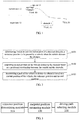
- FIG. 2 is a flow chart illustrating a method for plan a path for lane changing according to an embodiment of the present disclosure. As illustrated in FIG. 2 , the method for plan a path for lane changing includes following.
- a reference position to be passed by a vehicle when the vehicle detours an obstacle is determined based on position information of the obstacle.
- an end position of the vehicle detouring the obstacle is estimated based on a positional relationship between the vehicle and the obstacle.
- a path of the vehicle to detour the obstacle is determined based on a current position of the vehicle, the reference position and the end position.
- the end position of the vehicle detouring the obstacle may be estimated based on the positional relationship between the obstacle and the ego car, thereby a path starting from the current position of the vehicle and passing through the reference position and the end position is planned, keeping a safe distance between the ego car and the detected obstacle during driving.
- the method before determining the reference position to be passed by the vehicle when the vehicle detours the obstacle based on the position information of the obstacle, the method also includes: detecting the position information of the obstacle and a motion state of the obstacle before the vehicle starts lane changing.
- the solution of embodiments of the present disclosure may be applied to a lane changing scene in autonomous driving, the position information of the obstacle and the motion state of the obstacle may be detected before the vehicle starts the lane changing, the end position of the lane changing is estimated by utilizing the position information of the obstacle, and a path that may avoid the obstacle is planned.
- actions at block S110 may include: S21, obtaining a boundary position of the obstacle close to the vehicle from the position of the obstacle; and S22, calculating a position with a predetermined deviation distance from the boundary position, to obtain the reference position to be passed by the vehicle when the vehicle detours the obstacle.
- the predetermined deviation distance is a preset spacing distance between the obstacle and the vehicle in a direction perpendicular to a road centerline, and the predetermined deviation distance is greater than 0.
- the method for plan a path for lane changing may include: estimating the end position of the vehicle detouring the obstacle based on the current position and a motion state of the vehicle, as well as the position information and the motion state of the detected obstacle.
- estimating the end position of the vehicle detouring the obstacle may include: S31, determining the positional relationship between the vehicle and the obstacle while the vehicle is driving based on the current position and the motion state of the vehicle, as well as the position information and the motion state of the obstacle; and S32, estimating the end position of the vehicle detouring the obstacle by utilizing the positional relationship between the vehicle and the obstacle while the vehicle is driving.
- the position of the obstacle is fixed and the motion state of the obstacle is a static state.
- the positional relationship between the vehicle and the obstacle changes dynamically with the driving procedure of the vehicle.
- the end position of the vehicle which may avoid the obstacle during lane changing is estimated based on a dynamic positional relationship between the vehicle and the obstacle.
- estimating the end position that may avoid the obstacle during the lane changing may include: training a model for estimating the end position of the vehicle detouring the obstacle by utilizing positions of a vehicle, motion states of the vehicle, positions of an obstacle and motion states of the obstacle in advance, and estimating the end position of the vehicle that may avoid the obstacle by utilizing the trained model.
- actions at block S130 may include: S41, taking the current position of the vehicle, the reference position and the end position as trajectory points on the path of the vehicle detouring the obstacle; S42, calculating a driving angular velocity of the vehicle from the current position to the end position in a direction along the road centerline; and S43, establishing a path passing through the trajectory points at the driving angular velocity as the path of the vehicle to detour the obstacle.
- actions at block S42 may include: S51, calculating a driving path length of the vehicle from the current position to the end position in the direction along the road centerline based on a distance between the current position of the vehicle and the estimated end distance; S52, calculating a driving linear velocity of the vehicle based on the motion state of the vehicle and the path length; and S53, calculating the driving angular velocity of the vehicle from the current position to the end position by utilizing a conversion relationship between the driving linear velocity and the driving angular velocity.
- st - s 0 represents the driving path length of the vehicle from the current position to the end position in the direction along the road centerline
- b represents the driving angular velocity of the vehicle from the current position to the end position.
- b represents the driving angular velocity of the vehicle detouring the obstacle.
- the driving angular velocity may be used to measure somatosensory and linear stability of the vehicle during driving.
- a value of b depends on the positional relationship between the vehicle and the obstacle.
- the positional relationship includes both position relationship between the vehicle and the obstacle in the direction along the road centerline and position relationship between the vehicle and the obstacle in the direction perpendicular to the road centerline.
- the distance for lane changing may be estimated by utilizing the position information of the obstacle at the start of the lane changing, and the path for lane changing may be planned in combination with the positional relationship between the obstacle and the vehicle, thereby avoiding the obstacle, ensuring the safety during lane changing, and implementing the optimal somatosensory and linear stability.
- FIG. 3 is a block diagram illustrating an apparatus for plan a path for lane changing according to embodiments of the present disclosure.
- the apparatus for plan a path for lane changing includes a reference position determining module 310, an end position estimating module 320 and a driving path selecting module 330.
- the reference position determining module 310 is configured to determine, based on position information of a detected obstacle, a reference position to be passed by a vehicle when the vehicle detours the obstacle.
- the end position estimating module 320 is configured to estimate an end position of the vehicle detouring the obstacle by a positional relationship between the vehicle and the obstacle.
- the driving path selecting module 330 is configured to determine a path of the vehicle to detour the obstacle based on a current position of the vehicle, the reference position and the end position.
- the end position of the vehicle detouring the obstacle is estimated based on the positional relationship between the vehicle and the obstacle, thereby a path staring from the current position of the vehicle and passing through the reference position and the end position is planned, keeping a safe distance between the vehicle and the detected obstacle during driving.
- the apparatus for plan a path for lane changing may also include an information detecting module, configured to detect the position information of the obstacle and a motion state of the obstacle before the vehicle starts lane changing.
- the reference position determining module 310 may include: a boundary position obtaining unit and a reference position calculating unit.
- the boundary position obtaining unit is configured to obtain a boundary position of the obstacle close to the vehicle from the position information of the obstacle.
- the reference position calculating unit is configured to calculate a position with a predetermined deviation distance from the boundary position, to obtain the reference position to be passed by the vehicle when the vehicle detours the obstacle.
- the predetermined deviation distance is a preset spacing distance between the obstacle and the vehicle in a direction perpendicular to a road centerline, and the predetermined deviation distance is greater than 0.
- the end position estimating module 320 may also be configured to estimate the end position of the vehicle detouring the obstacle based on the current position and a motion state of the vehicle, as well as the position and a motion state of the obstacle.
- the end position estimating module 320 may also include: a positional relationship determining unit, configured to determine the positional relationship between the vehicle and the obstacle while the vehicle is driving based on the current position and the motion state of the vehicle, and the position and the motion state of the obstacle.
- the end position estimating module 320 may also be configured to estimate the end position of the vehicle detouring the obstacle by utilizing the positional relationship between the vehicle and the obstacle while the vehicle is driving.
- the driving path selecting module 330 may include: a trajectory point determining unit, an angular velocity calculating unit and a path establishing unit.
- the trajectory point determining unit is configured to take the current position of the vehicle, the reference position and the end position as trajectory points on the path of the vehicle detouring the obstacle.
- the angular velocity calculating unit is configured to calculate a driving angular velocity of the vehicle from the current position to the end position in a direction along the road centerline.
- the path establishing unit is configured to establish a path passing through the trajectory points at the driving angular velocity as the path of the vehicle to detour the obstacle.
- the angular velocity calculating unit may include: a driving length calculating subunit, a linear velocity calculating subunit and an angular velocity calculating subunit.
- the driving length calculating subunit is configured to calculate a driving path length of the vehicle from the current position to the end position in the direction along the road centerline based on a distance between the current position of the vehicle and the estimated end position.
- the linear velocity calculating subunit is configured to calculate a driving linear velocity of the vehicle based on the motion state of the vehicle and the driving path length.
- the angular velocity calculating subunit is configured to calculate the driving angular velocity of the vehicle from the current position to the end position by utilizing a conversion relationship between the driving linear velocity and the driving angular velocity.
- the distance for lane changing may be estimated by utilizing the position information of the obstacle at the start of the lane changing, and the path for lane changing may be planned in combination with the positional relationship between the obstacle and the vehicle, thereby avoiding the obstacle, ensuring the safety during lane changing, and implementing optimal somatosensory and linear stability.
- FIG. 4 is a block diagram illustrating an electronic device according to embodiments of the present disclosure. As illustrated in FIG. 4 , embodiments of the present disclosure provide an electronic device 400.
- the electronic device includes one or more processors 401, a memory 402, and one or more I/O (input/output) interfaces 403.
- the memory 402 has one or more programs stored thereon. When the one or more programs are executed by the one or more processors, the one or more processors are caused to implement the method for plan a path for lane changing according to any one of the above.
- the I/O (input/output) interface 403 are coupled between the processor and the memory, and configured to implement information interaction between the processor and the memory.
- the processor 401 is a component with data processing capability, including but not limited to a central processing unit (CPU).
- the memory 402 is a component with data storage capability, including but not limited to a random access memory (RAM, more specifically a SDRAM (synchronous dynamic random-access memory), DDR (double data rate), etc.), a read-only memory (ROM), an electrically erasable programmable read-only memory (EEPROM), and a flash memory.
- the I/O (input/output) interface 403 is coupled between the processor 401 and the memory 402, to implement the information interaction between the processor 401 and the memory 402, and include but not limit to a data bus.
- the processor 401, the memory 402, and the I/O interface 403 are coupled to each other by a bus 404, and further coupled to other components of the electronic device 500.
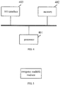
- FIG. 5 is a block diagram illustrating a computer readable medium according to embodiments of the present disclosure. As illustrated in FIG. 5 , embodiments of the present disclosure provide a computer readable medium having a computer program stored thereon. The computer program is configured to implement the method for plan a path for lane changing according to any one of the above when executed by a processor.
- all the methods or some of the functional modules/units in the device, the steps, and the system may be implemented as software, firmware, hardware and appropriate combinations thereof.
- the division among the functional modules/units mentioned in the above description does not necessarily correspond to the division of physical components.
- one physical component may have a plurality of functions, or one function or one step may be cooperatively performed by several physical components.
- Some or all of the physical components may be implemented as the software executed by a processor, such as a central processing unit, a digital signal processor or a microprocessor, as hardware, or as an integrated circuit, such as an application specific integrated circuit.
- a processor such as a central processing unit, a digital signal processor or a microprocessor
- Such software may be distributed on a computer-readable medium.
- the computer-readable medium may include a computer storage medium (or non-transitory medium) and a communication medium (or transitory medium).
- a computer storage medium or non-transitory medium
- a communication medium or transitory medium
- computer storage medium includes a volatile and nonvolatile medium and a removable and non-removable medium implemented in any method or technology for storing information such as computer readable instructions, data structures, program modules or other data.
- the computer storage medium includes, but is not limited to, a storage technology such as a RAM, a ROM, an EEPROM, or a flash memory, an optical disk storage such as a CD-ROM or a digital versatile disk (DVD), a magnetic storage device such as a magnetic box, a magnetic tape or magnetic disk storage, or any other medium that may be used to store desired information and accessed by a computer.
- the communication medium typically includes the computer readable instructions, the data structures, the program modules or other data in a modulated data signal such as a carrier wave or other transmission mechanism, and may include any information delivery media.
Landscapes
- Engineering & Computer Science (AREA)
- Automation & Control Theory (AREA)
- Transportation (AREA)
- Mechanical Engineering (AREA)
- Physics & Mathematics (AREA)
- Radar, Positioning & Navigation (AREA)
- Remote Sensing (AREA)
- General Physics & Mathematics (AREA)
- Mathematical Physics (AREA)
- Human Computer Interaction (AREA)
- Theoretical Computer Science (AREA)
- Multimedia (AREA)
- Traffic Control Systems (AREA)
- Control Of Driving Devices And Active Controlling Of Vehicle (AREA)
- Aviation & Aerospace Engineering (AREA)
Abstract
Description
- Embodiments of the present disclosure relate to a field of autonomous driving technologies, and more particularly to a method and an apparatus for plan a path for lane changing, an electronic device, and a computer readable medium.
- With development of computer technologies and artificial intelligence, an autonomous vehicle has a broad application prospect in transportation, military affairs, logistics storage, daily life and so on.
- Path planning is a key part of autonomous driving technologies, which is based on environmental data of a perceptual system. A vehicle needs to plan a safe and reliable path, that is, a shortest and collision-free path from a start position to a target position in a complex road environment based on certain performance indicators. Meanwhile, it is necessary to ensure that the vehicle has a certain safe distance to an obstacle during driving.
- Embodiments of the present disclosure provide a method and an apparatus for plan a path for lane changing, an electronic device, and a computer readable medium, which may ensure that the vehicle has a certain safe distance to an obstacle during driving in the path.
- In a first aspect, embodiments of the present disclosure provide a method for plan a path for lane changing. The method includes: determining, based on position information of a detected obstacle, a reference position to be passed by a vehicle when the vehicle detours the obstacle; estimating an end position of the vehicle detouring the obstacle by a positional relationship between the vehicle and the obstacle; and determining a path of the vehicle to detour the obstacle based on a current position of the vehicle, the reference position and the end position.
- In a second aspect, embodiments of the present disclosure provide an apparatus for plan a path for lane changing. The apparatus includes: a reference position determining module, an end position estimating module and a driving path selecting module. The reference position determining module is configured to determine, based on position information of a detected obstacle, a reference position to be passed by a vehicle when the vehicle detours the obstacle. The end position estimating module is configured to estimate an end position of the vehicle detouring the obstacle by a positional relationship between the vehicle and the obstacle. The driving path selecting module is configured to determine a path of the vehicle to detour the obstacle based on a current position of the vehicle, the reference position and the end position.
- In a third aspect, embodiments of the present disclosure provide an electronic device. The electronic device includes: one or more processors, a storage device and one or more I/O interfaces. The storage device has one or more programs stored thereon. When the one or more programs are executed by the one or more processors, the one or more processors are caused to implement the method for plan a path for lane changing according to any one of the above. The one or more I/O interfaces are coupled between the one or more processors and the storage device, and configured to implement information interaction between the one or more processors and the storage device,
- In a fourth aspect, embodiments of the present disclosure provide a computer readable medium. The computer readable medium has a computer program stored thereon. The method for plan a path for lane changing according to any one of the above is implemented when the computer program is executed by a processor.
- With the method and the apparatus for plan a path for lane changing, the electronic device, and the computer readable medium, the reference position to be passed by the vehicle when the vehicle detours the obstacle is calculated, and the end position of the vehicle detouring the obstacle is estimated based on the positional relationship between the vehicle and the obstacle, thereby the path of the vehicle to detour the obstacle is planned, keeping a safe distance between the vehicle and the detected obstacle during driving.
- The accompanying drawings are used to provide a further understanding for embodiments of the present disclosure and constitute a part of the specification, and are used to explain the present disclosure together with the embodiments of the present disclosure, but do not constitute a limitation of the present disclosure. The above and other features and advantages may become more apparent to the skilled in the art by describing detailed exemplary embodiments with reference to the accompanying drawings, in which:
-
FIG. 1 is a schematic diagram illustrating a scene where an autonomous vehicle detours an obstacle during lane changing according to an embodiment of the present disclosure; -
FIG. 2 is a flow chart illustrating a method for plan a path for lane changing according to an embodiment of the present disclosure; -
FIG. 3 is a block diagram illustrating an apparatus for plan a path for lane changing according to an embodiment of the present disclosure; -
FIG. 4 is a block diagram illustrating an electronic device according to an embodiment of the present disclosure; and -
FIG. 5 is a block diagram illustrating a computer readable medium according to an embodiment of the present disclosure. - In order to enable the skilled in the art to better understand the technical solution of the present disclosure, description may be made in detail below to a method and an apparatus for plan a path for lane changing, an electronic device and a computer readable medium provided by the present disclosure with reference to the accompanying drawings.
- Exemplary embodiments may be described more fully below with reference to the accompanying drawings, but may be embodied in different forms and should not be construed as a limitation of embodiments set forth herein. On the contrary, these provided embodiments aim to enable the present disclosure thorough and complete, and enable the skilled in the art to fully understand the scope of the present disclosure. Each embodiments of the present disclosure and the features in the embodiments may be combined with each other without conflict.
- A vehicle described in embodiments of the present disclosure may be an autonomous vehicle or a self-driving automobile. The vehicle may be configured to be in an autonomous driving mode. In the autonomous driving mode, the vehicle may be navigated to pass through an environment with little or no input from a driver. In following embodiments, the vehicle may also be called an ego car, that is, a vehicle that may sense the environment with an angle of itself and plan a path for lane changing with itself as the center.
-
FIG. 1 is a schematic diagram illustrating a scene where an autonomous vehicle detours an obstacle during lane changing according to an embodiment of the present disclosure. In the scene illustrated inFIG. 1 , acurrent lane 12, atarget lane 13 and anobstacle 1 located in thetarget lane 13 are schematically illustrated during lane changing process of theego car 11 of the autonomous vehicle. - In embodiments of the present disclosure, during the driving process of the
ego car 11, theego car 11 may detect position information and a motion state of theego car 11, and may detect position information and a motion state of the obstacle. For example, the motion state may include information such as a motion direction and a motion velocity. - In an embodiment, a coordinate system may be constructed based on a direction along a road centerline (referred as a vertical direction) during driving process of the vehicle drives and a direction perpendicular to the road centerline (referred as a horizontal direction), thereby the position information of the
ego car 11 and the position information of the detected obstacle in the constructed coordinate system are determined. -
FIG. 1 exemplarily illustrates a current position T1(s0, 10) of theego car 11, a reference position T2(s1, 11) to be passed by the ego car when theego car 11 detours thefirst obstacle 1, and an estimated end position T3(st, It) of the vehicle detouring thefirst obstacle 1. - The
first obstacle 1 includes two boundaries: one boundary close to theego car 11 and the other boundary far away from theego car 11. In addition, a predetermined deviation distance may be maintained between theego car 11 and the boundary of thefirst obstacle 1 close to theego car 11 in the direction perpendicular to the road centerline. - With the method for plan a path for lane changing, by utilizing the reference position, an end position where the obstacle may be avoided may be determined, and a driving path where the obstacle may be avoided may be planned.
- It should be noted that, the actual scene for planning a path for lane changing illustrated in
FIG. 1 may be an application scene of planning a path for lane changing on an expressway, a medium and low speed highway, or other application scene, which is not limited in embodiments of the present disclosure. -
FIG. 2 is a flow chart illustrating a method for plan a path for lane changing according to an embodiment of the present disclosure. As illustrated inFIG. 2 , the method for plan a path for lane changing includes following. - At block S110, a reference position to be passed by a vehicle when the vehicle detours an obstacle is determined based on position information of the obstacle.
- At block S120, an end position of the vehicle detouring the obstacle is estimated based on a positional relationship between the vehicle and the obstacle.
- At block S130, a path of the vehicle to detour the obstacle is determined based on a current position of the vehicle, the reference position and the end position.
- In a solution of embodiments of the present disclosure, the end position of the vehicle detouring the obstacle may be estimated based on the positional relationship between the obstacle and the ego car, thereby a path starting from the current position of the vehicle and passing through the reference position and the end position is planned, keeping a safe distance between the ego car and the detected obstacle during driving.
- In an embodiment, before determining the reference position to be passed by the vehicle when the vehicle detours the obstacle based on the position information of the obstacle, the method also includes: detecting the position information of the obstacle and a motion state of the obstacle before the vehicle starts lane changing.
- The solution of embodiments of the present disclosure may be applied to a lane changing scene in autonomous driving, the position information of the obstacle and the motion state of the obstacle may be detected before the vehicle starts the lane changing, the end position of the lane changing is estimated by utilizing the position information of the obstacle, and a path that may avoid the obstacle is planned.
- In an embodiment, actions at block S110 may include: S21, obtaining a boundary position of the obstacle close to the vehicle from the position of the obstacle; and S22, calculating a position with a predetermined deviation distance from the boundary position, to obtain the reference position to be passed by the vehicle when the vehicle detours the obstacle.
- In an embodiment, the predetermined deviation distance is a preset spacing distance between the obstacle and the vehicle in a direction perpendicular to a road centerline, and the predetermined deviation distance is greater than 0.
- As an example, estimating position information of a position point to be detoured by utilizing the position of the detected obstacle may be expressed as a following expression (1):

- It may be known from the expression (1) that, in this embodiment, by setting the predetermined deviation distance, a degree of keeping a safe distance between the vehicle and the obstacle may be adjusted, thereby ensuring that the obstacle may be avoided during normal driving or lane changing.
- In an embodiment, the method for plan a path for lane changing may include: estimating the end position of the vehicle detouring the obstacle based on the current position and a motion state of the vehicle, as well as the position information and the motion state of the detected obstacle.
- In this embodiment, estimating the end position of the vehicle detouring the obstacle may include: S31, determining the positional relationship between the vehicle and the obstacle while the vehicle is driving based on the current position and the motion state of the vehicle, as well as the position information and the motion state of the obstacle; and S32, estimating the end position of the vehicle detouring the obstacle by utilizing the positional relationship between the vehicle and the obstacle while the vehicle is driving.
- In the method for plan a path for lane changing, when the obstacle is static, the position of the obstacle is fixed and the motion state of the obstacle is a static state. When the obstacle is dynamic, the positional relationship between the vehicle and the obstacle changes dynamically with the driving procedure of the vehicle. The end position of the vehicle which may avoid the obstacle during lane changing is estimated based on a dynamic positional relationship between the vehicle and the obstacle.
- In an embodiment, estimating the end position that may avoid the obstacle during the lane changing may include: training a model for estimating the end position of the vehicle detouring the obstacle by utilizing positions of a vehicle, motion states of the vehicle, positions of an obstacle and motion states of the obstacle in advance, and estimating the end position of the vehicle that may avoid the obstacle by utilizing the trained model.
- In an embodiment, actions at block S130 may include: S41, taking the current position of the vehicle, the reference position and the end position as trajectory points on the path of the vehicle detouring the obstacle; S42, calculating a driving angular velocity of the vehicle from the current position to the end position in a direction along the road centerline; and S43, establishing a path passing through the trajectory points at the driving angular velocity as the path of the vehicle to detour the obstacle.
- In an embodiment, actions at block S42 may include: S51, calculating a driving path length of the vehicle from the current position to the end position in the direction along the road centerline based on a distance between the current position of the vehicle and the estimated end distance; S52, calculating a driving linear velocity of the vehicle based on the motion state of the vehicle and the path length; and S53, calculating the driving angular velocity of the vehicle from the current position to the end position by utilizing a conversion relationship between the driving linear velocity and the driving angular velocity.
- As an example, a constructed curve of the ego car detouring (or moving around) the obstacle may be represented as an expression (2):

- Moreover, in the expression (2), st - s0 represents the driving path length of the vehicle from the current position to the end position in the direction along the road centerline , and b represents the driving angular velocity of the vehicle from the current position to the end position.
- In an embodiment, the parameters a, b and c for constructing the curve of the vehicle detouring the obstacle are obtained by solving the above expression (2), in which,

- It may be known from the above description that, b represents the driving angular velocity of the vehicle detouring the obstacle. The driving angular velocity may be used to measure somatosensory and linear stability of the vehicle during driving. A value of b depends on the positional relationship between the vehicle and the obstacle. The positional relationship includes both position relationship between the vehicle and the obstacle in the direction along the road centerline and position relationship between the vehicle and the obstacle in the direction perpendicular to the road centerline.
- Therefore, based on the method for plan a path for lane changing of embodiments of the present disclosure, , the distance for lane changing may be estimated by utilizing the position information of the obstacle at the start of the lane changing, and the path for lane changing may be planned in combination with the positional relationship between the obstacle and the vehicle, thereby avoiding the obstacle, ensuring the safety during lane changing, and implementing the optimal somatosensory and linear stability.
-
FIG. 3 is a block diagram illustrating an apparatus for plan a path for lane changing according to embodiments of the present disclosure. As illustrated inFIG. 3 , the apparatus for plan a path for lane changing includes a referenceposition determining module 310, an endposition estimating module 320 and a drivingpath selecting module 330. - The reference
position determining module 310 is configured to determine, based on position information of a detected obstacle, a reference position to be passed by a vehicle when the vehicle detours the obstacle. - The end
position estimating module 320 is configured to estimate an end position of the vehicle detouring the obstacle by a positional relationship between the vehicle and the obstacle. - The driving
path selecting module 330 is configured to determine a path of the vehicle to detour the obstacle based on a current position of the vehicle, the reference position and the end position. - With the apparatus for plan a path for lane changing according to embodiments of the present disclosure, the end position of the vehicle detouring the obstacle is estimated based on the positional relationship between the vehicle and the obstacle, thereby a path staring from the current position of the vehicle and passing through the reference position and the end position is planned, keeping a safe distance between the vehicle and the detected obstacle during driving.
- In an embodiment, the apparatus for plan a path for lane changing may also include an information detecting module, configured to detect the position information of the obstacle and a motion state of the obstacle before the vehicle starts lane changing.
- In an embodiment, the reference
position determining module 310 may include: a boundary position obtaining unit and a reference position calculating unit. The boundary position obtaining unit is configured to obtain a boundary position of the obstacle close to the vehicle from the position information of the obstacle. The reference position calculating unit is configured to calculate a position with a predetermined deviation distance from the boundary position, to obtain the reference position to be passed by the vehicle when the vehicle detours the obstacle. - In an embodiment, the predetermined deviation distance is a preset spacing distance between the obstacle and the vehicle in a direction perpendicular to a road centerline, and the predetermined deviation distance is greater than 0.
- In an embodiment, the end
position estimating module 320 may also be configured to estimate the end position of the vehicle detouring the obstacle based on the current position and a motion state of the vehicle, as well as the position and a motion state of the obstacle. - In an embodiment, the end
position estimating module 320 may also include: a positional relationship determining unit, configured to determine the positional relationship between the vehicle and the obstacle while the vehicle is driving based on the current position and the motion state of the vehicle, and the position and the motion state of the obstacle. The endposition estimating module 320 may also be configured to estimate the end position of the vehicle detouring the obstacle by utilizing the positional relationship between the vehicle and the obstacle while the vehicle is driving. - In an embodiment, the driving
path selecting module 330 may include: a trajectory point determining unit, an angular velocity calculating unit and a path establishing unit. The trajectory point determining unit is configured to take the current position of the vehicle, the reference position and the end position as trajectory points on the path of the vehicle detouring the obstacle. The angular velocity calculating unit is configured to calculate a driving angular velocity of the vehicle from the current position to the end position in a direction along the road centerline. The path establishing unit is configured to establish a path passing through the trajectory points at the driving angular velocity as the path of the vehicle to detour the obstacle. - In an embodiment, the angular velocity calculating unit may include: a driving length calculating subunit, a linear velocity calculating subunit and an angular velocity calculating subunit. The driving length calculating subunit is configured to calculate a driving path length of the vehicle from the current position to the end position in the direction along the road centerline based on a distance between the current position of the vehicle and the estimated end position. The linear velocity calculating subunit is configured to calculate a driving linear velocity of the vehicle based on the motion state of the vehicle and the driving path length. The angular velocity calculating subunit is configured to calculate the driving angular velocity of the vehicle from the current position to the end position by utilizing a conversion relationship between the driving linear velocity and the driving angular velocity.
- With the apparatus for plan a path for lane changing according to embodiments of the present disclosure, at the start of lane changing, the distance for lane changing may be estimated by utilizing the position information of the obstacle at the start of the lane changing, and the path for lane changing may be planned in combination with the positional relationship between the obstacle and the vehicle, thereby avoiding the obstacle, ensuring the safety during lane changing, and implementing optimal somatosensory and linear stability.
-
FIG. 4 is a block diagram illustrating an electronic device according to embodiments of the present disclosure. As illustrated inFIG. 4 , embodiments of the present disclosure provide an electronic device 400. The electronic device includes one ormore processors 401, amemory 402, and one or more I/O (input/output) interfaces 403. Thememory 402 has one or more programs stored thereon. When the one or more programs are executed by the one or more processors, the one or more processors are caused to implement the method for plan a path for lane changing according to any one of the above. The I/O (input/output)interface 403 are coupled between the processor and the memory, and configured to implement information interaction between the processor and the memory. - The
processor 401 is a component with data processing capability, including but not limited to a central processing unit (CPU). Thememory 402 is a component with data storage capability, including but not limited to a random access memory (RAM, more specifically a SDRAM (synchronous dynamic random-access memory), DDR (double data rate), etc.), a read-only memory (ROM), an electrically erasable programmable read-only memory (EEPROM), and a flash memory. The I/O (input/output)interface 403 is coupled between theprocessor 401 and thememory 402, to implement the information interaction between theprocessor 401 and thememory 402, and include but not limit to a data bus. - In some embodiments, the
processor 401, thememory 402, and the I/O interface 403 are coupled to each other by a bus 404, and further coupled to other components of the electronic device 500. -
FIG. 5 is a block diagram illustrating a computer readable medium according to embodiments of the present disclosure. As illustrated inFIG. 5 , embodiments of the present disclosure provide a computer readable medium having a computer program stored thereon. The computer program is configured to implement the method for plan a path for lane changing according to any one of the above when executed by a processor. - It may be understood by the skilled in the art that, all the methods or some of the functional modules/units in the device, the steps, and the system may be implemented as software, firmware, hardware and appropriate combinations thereof. In a hardware implementation, the division among the functional modules/units mentioned in the above description does not necessarily correspond to the division of physical components. For example, one physical component may have a plurality of functions, or one function or one step may be cooperatively performed by several physical components. Some or all of the physical components may be implemented as the software executed by a processor, such as a central processing unit, a digital signal processor or a microprocessor, as hardware, or as an integrated circuit, such as an application specific integrated circuit. Such software may be distributed on a computer-readable medium. The computer-readable medium may include a computer storage medium (or non-transitory medium) and a communication medium (or transitory medium). As well known to the skilled in the art, the term "computer storage medium" includes a volatile and nonvolatile medium and a removable and non-removable medium implemented in any method or technology for storing information such as computer readable instructions, data structures, program modules or other data. The computer storage medium includes, but is not limited to, a storage technology such as a RAM, a ROM, an EEPROM, or a flash memory, an optical disk storage such as a CD-ROM or a digital versatile disk (DVD), a magnetic storage device such as a magnetic box, a magnetic tape or magnetic disk storage, or any other medium that may be used to store desired information and accessed by a computer. Furthermore, it is well known to the skilled in the art that, the communication medium typically includes the computer readable instructions, the data structures, the program modules or other data in a modulated data signal such as a carrier wave or other transmission mechanism, and may include any information delivery media.
- Exemplary embodiments are disclosed herein. Although detailed terms are employed, the terms are merely used and should merely be interpreted in a general illustrative sense, and are not used for the purpose of limitation. In some embodiments, it is obvious to the skilled in the art that the features, characteristics and/or elements described in connection with detailed embodiments may be used alone or in combination with features, characteristics and/or elements described in connection with other embodiments, unless explicitly stated otherwise. Therefore, it may be understood by the skilled in the art that, various changes in form and details may be made without departing from the scope of the present disclosure as set forth in the appended claims.
Claims (15)
- A method for planning a path for lane changing, comprising:determining (S101), based on position information of a detected obstacle, a reference position to be passed by a vehicle when the vehicle detours the obstacle;estimating (S102) an end position of the vehicle detouring the obstacle based on a positional relationship between the vehicle and the obstacle; anddetermining (S103) a path of the vehicle to detour the obstacle based on a current position of the vehicle, the reference position and the end position.
- The method of claim 1, wherein, before determining (S101) the reference position to be passed by the vehicle when the vehicle detours the detected obstacle based on the position information of the obstacle, the method further comprises:
detecting the position information of the obstacle and a motion state of the obstacle before the vehicle starts lane changing. - The method of claim 1 or 2, wherein determining (S101) the reference position to be passed by the vehicle when the vehicle detours the detected obstacle based on the position information of the obstacle comprises:obtaining a boundary position of the obstacle close to the vehicle from the position information of the obstacle; andcalculating a position with a predetermined deviation distance from the boundary position, to obtain the reference position to be passed by the vehicle when the vehicle detours the obstacle,wherein the predetermined deviation distance is a preset spacing distance between the obstacle and the vehicle in a direction perpendicular to a road centerline, and the predetermined deviation distance is greater than 0.
- The method of any one of claims 1 to 3, wherein estimating (S102) the end position of the vehicle detouring the obstacle based on the positional relationship between the vehicle and the obstacle comprises:
estimating the end position of the vehicle detouring the obstacle based on the current position and a motion state of the vehicle, and the position information and a motion state of the obstacle. - The method of claim 4, wherein the positional relationship between the vehicle and the obstacle while the vehicle is driving is determined based on the current position and a motion state of the vehicle, and the position information and a motion state of the obstacle.
- The method of any of claims 1-5, wherein determining (S103) the path of the vehicle to detour the obstacle based on the current position of the vehicle, the reference position and the end position comprises:taking the current position of the vehicle, the reference position and the end position as trajectory points on the path of the vehicle detouring the obstacle;calculating a driving angular velocity of the vehicle from the current position to the end position in a direction along the road centerline; andestablishing a path passing through the trajectory points at the driving angular velocity as the path of the vehicle to detour the obstacle.
- The method of claim 6, wherein calculating the driving angular velocity of the vehicle from the current position to the end position in the direction along the road centerline comprises:calculating a driving path length of the vehicle from the current position to the end position in the direction along the road centerline based on a distance between the current position of the vehicle and the estimated end position;calculating a driving linear velocity of the vehicle based on a motion state of the vehicle and the driving path length; andcalculating the driving angular velocity of the vehicle from the current position to the end position by utilizing a conversion relationship between the driving linear velocity and the driving angular velocity.
- An apparatus for planning a path for lane changing, comprising:a reference position determining module (310), configured to determine, based on position information of a detected obstacle, a reference position to be passed by a vehicle when the vehicle detours the obstacle;an end position estimating module (320), configured to estimate an end position of the vehicle detouring the obstacle based on a positional relationship between the vehicle and the obstacle; anda driving path selecting module (330), configured to determine a path of the vehicle to detour the obstacle based on a current position of the vehicle, the reference position and the end position.
- The apparatus of claim 8, wherein the apparatus further comprises:
an information detecting module, configured to detect the position information of the obstacle and a motion state of the obstacle before the vehicle starts lane changing. - The apparatus of claim 8 or 9, wherein the reference position determining module (310) comprises:a boundary position obtaining unit, configured to obtain a boundary position of the obstacle close to the vehicle from the position information of the obstacle; anda reference position calculating unit, configured to calculate a position with a predetermined deviation distance from the boundary position, to obtain the reference position to be passed by the vehicle when the vehicle detours the obstacle,wherein the predetermined deviation distance is a preset spacing distance between the obstacle and the vehicle in a direction perpendicular to a road centerline, and the predetermined deviation distance is greater than 0.
- The apparatus of any one of claims 8 to 10, wherein the end position estimating module (320) is further configured to estimate the end position of the vehicle detouring the obstacle based on the current position and a motion state of the vehicle, and the position information and a motion state of the obstacle.
- The apparatus of claim 8, wherein the end position estimating module (320) comprises:a positional relationship determining unit, configured to determine the positional relationship between the vehicle and the obstacle while the vehicle is driving based on the current position and a motion state of the vehicle, and the position and a motion state of the obstacle,wherein, the end position estimating module is further configured to estimate the end position of the vehicle detouring the obstacle by utilizing the positional relationship between the vehicle and the obstacle while the vehicle is driving.
- An electronic device, comprising:one or more processors;a storage device having one or more programs stored thereon that, when executed by the one or more processors, cause the one or more processors to implement the method for planning a path for lane changing according to any one of claims 1-7; andone or more I/O interfaces, coupled between the one or more processors and the storage device and configured to implement information interaction between the one or more processors and the storage device.
- A computer readable medium having a computer program stored thereon, wherein the method for planning a path for lane changing according to any one of claims 1-7 is implemented when the computer program is executed by a processor.
- A computer program having a computer program stored therein, wherein the method for planning a path for lane changing according to any one of claims 1-7 is implemented when the computer program is executed by a processor.
Applications Claiming Priority (1)
| Application Number | Priority Date | Filing Date | Title |
|---|---|---|---|
| CN202010081762.4A CN111238520B (en) | 2020-02-06 | 2020-02-06 | Automatic driving lane change path planning method and device and electronic equipment |
Publications (1)
| Publication Number | Publication Date |
|---|---|
| EP3862241A1 true EP3862241A1 (en) | 2021-08-11 |
Family
ID=70863128
Family Applications (1)
| Application Number | Title | Priority Date | Filing Date |
|---|---|---|---|
| EP21150227.3A Withdrawn EP3862241A1 (en) | 2020-02-06 | 2021-01-05 | Method and apparatus for planning path for lane changing, electronic device and computer readable medium |
Country Status (5)
| Country | Link |
|---|---|
| US (1) | US20210245786A1 (en) |
| EP (1) | EP3862241A1 (en) |
| JP (1) | JP7320008B2 (en) |
| KR (1) | KR20210100553A (en) |
| CN (1) | CN111238520B (en) |
Cited By (2)
| Publication number | Priority date | Publication date | Assignee | Title |
|---|---|---|---|---|
| CN114777804A (en) * | 2022-04-21 | 2022-07-22 | 国汽智控(北京)科技有限公司 | Path planning method, device and equipment and readable storage medium |
| CN115743182A (en) * | 2022-11-30 | 2023-03-07 | 深圳元戎启行科技有限公司 | Bypassing method and control method of automatic driving vehicle and vehicle-mounted equipment |
Families Citing this family (16)
| Publication number | Priority date | Publication date | Assignee | Title |
|---|---|---|---|---|
| CN111724598B (en) * | 2020-06-29 | 2022-04-05 | 北京百度网讯科技有限公司 | Method, apparatus, device, and storage medium for planning a path for autonomous driving |
| CN112265542B (en) * | 2020-09-11 | 2022-05-27 | 武汉智行者科技有限公司 | Automatic driving meeting scene processing method and device and vehicle |
| CN113804208B (en) * | 2020-09-18 | 2024-05-17 | 北京京东乾石科技有限公司 | Unmanned vehicle path optimization method and related equipment |
| CN114537381B (en) * | 2020-11-24 | 2024-05-31 | 宇通客车股份有限公司 | Lane obstacle avoidance method and device for automatic driving vehicle |
| US12585847B2 (en) * | 2020-12-23 | 2026-03-24 | Waymo Llc | Simulations for evaluating driving behaviors of autonomous vehicles |
| CN114684127A (en) * | 2020-12-29 | 2022-07-01 | 上海擎感智能科技有限公司 | Lane-changing trajectory planning method, electronic device and computer-readable storage medium |
| CN114852099B (en) * | 2021-02-03 | 2024-08-02 | 宇通客车股份有限公司 | Prediction method of lane-changing behavior of motor vehicles |
| CN113954838B (en) * | 2021-11-24 | 2023-04-07 | 上海安亭地平线智能交通技术有限公司 | Vehicle lane change control method and device, electronic device and storage medium |
| CN114323044B (en) * | 2021-12-16 | 2025-07-01 | 中汽创智科技有限公司 | A path planning method, device, equipment and storage medium |
| CN114379584B (en) * | 2021-12-17 | 2023-12-22 | 阿波罗智联(北京)科技有限公司 | Vehicle control method, device, vehicle, equipment and storage medium |
| CN114802269B (en) * | 2022-03-31 | 2025-09-09 | 广州文远知行科技有限公司 | Main vehicle motion planning method, system and computer readable storage medium |
| CN114750782A (en) * | 2022-04-19 | 2022-07-15 | 重庆兰德适普信息科技有限公司 | Path planning method, device and equipment and vehicle control method, device and equipment |
| CN115123216B (en) * | 2022-08-05 | 2025-06-06 | 国汽智控(北京)科技有限公司 | Vehicle obstacle avoidance method, device, vehicle, equipment and storage medium |
| CN115384552B (en) * | 2022-09-29 | 2024-09-06 | 阿波罗智能技术(北京)有限公司 | Control method and device of automatic driving vehicle and automatic driving vehicle |
| CN115535001A (en) * | 2022-11-01 | 2022-12-30 | 西安紫光展锐科技有限公司 | Control method, apparatus, device, medium, and program product for autonomous vehicle |
| CN116476840B (en) * | 2023-06-21 | 2023-09-01 | 北京斯年智驾科技有限公司 | Lane changing driving method, device, equipment and storage medium |
Citations (3)
| Publication number | Priority date | Publication date | Assignee | Title |
|---|---|---|---|---|
| DE102014016567A1 (en) * | 2014-11-08 | 2016-05-12 | GM Global Technology Operations LLC (n. d. Ges. d. Staates Delaware) | Method for determining an evasion trajectory and driver assistance system therefor |
| US9511767B1 (en) * | 2015-07-01 | 2016-12-06 | Toyota Motor Engineering & Manufacturing North America, Inc. | Autonomous vehicle action planning using behavior prediction |
| GB2562376A (en) * | 2017-03-31 | 2018-11-14 | Ford Global Tech Llc | Virtual Steerable Path |
Family Cites Families (9)
| Publication number | Priority date | Publication date | Assignee | Title |
|---|---|---|---|---|
| RU2566175C1 (en) * | 2011-08-31 | 2015-10-20 | Ниссан Мотор Ко., Лтд. | Vehicle driver aid |
| JP5919186B2 (en) | 2012-12-25 | 2016-05-18 | 日立建機株式会社 | Map creation support system |
| KR102036050B1 (en) * | 2014-12-30 | 2019-10-24 | 주식회사 만도 | Apparatuses and Methods for line changing |
| CN109050533B (en) * | 2017-06-09 | 2020-11-17 | 蔚来(安徽)控股有限公司 | Automatic lane changing control method and device for vehicle |
| CN107792073B (en) * | 2017-09-29 | 2019-10-25 | 东软集团股份有限公司 | A kind of vehicle lane-changing control method, device and relevant device |
| CN111315623B (en) | 2017-11-06 | 2022-10-21 | 本田技研工业株式会社 | Vehicle control device |
| JP2019159500A (en) * | 2018-03-08 | 2019-09-19 | トヨタ自動車株式会社 | Vehicle control device |
| JP2020004017A (en) | 2018-06-27 | 2020-01-09 | アイシン・エィ・ダブリュ株式会社 | Image data transmission device and image data transmission program |
| CN110103967B (en) * | 2019-05-15 | 2020-10-20 | 广州小鹏汽车科技有限公司 | Automatic lane changing method for vehicle, vehicle control system and vehicle |
-
2020
- 2020-02-06 CN CN202010081762.4A patent/CN111238520B/en active Active
- 2020-09-24 US US17/031,410 patent/US20210245786A1/en not_active Abandoned
-
2021
- 2021-01-05 EP EP21150227.3A patent/EP3862241A1/en not_active Withdrawn
- 2021-01-27 JP JP2021010793A patent/JP7320008B2/en active Active
- 2021-02-05 KR KR1020210016668A patent/KR20210100553A/en not_active Ceased
Patent Citations (3)
| Publication number | Priority date | Publication date | Assignee | Title |
|---|---|---|---|---|
| DE102014016567A1 (en) * | 2014-11-08 | 2016-05-12 | GM Global Technology Operations LLC (n. d. Ges. d. Staates Delaware) | Method for determining an evasion trajectory and driver assistance system therefor |
| US9511767B1 (en) * | 2015-07-01 | 2016-12-06 | Toyota Motor Engineering & Manufacturing North America, Inc. | Autonomous vehicle action planning using behavior prediction |
| GB2562376A (en) * | 2017-03-31 | 2018-11-14 | Ford Global Tech Llc | Virtual Steerable Path |
Cited By (2)
| Publication number | Priority date | Publication date | Assignee | Title |
|---|---|---|---|---|
| CN114777804A (en) * | 2022-04-21 | 2022-07-22 | 国汽智控(北京)科技有限公司 | Path planning method, device and equipment and readable storage medium |
| CN115743182A (en) * | 2022-11-30 | 2023-03-07 | 深圳元戎启行科技有限公司 | Bypassing method and control method of automatic driving vehicle and vehicle-mounted equipment |
Also Published As
| Publication number | Publication date |
|---|---|
| CN111238520B (en) | 2022-10-14 |
| JP7320008B2 (en) | 2023-08-02 |
| CN111238520A (en) | 2020-06-05 |
| KR20210100553A (en) | 2021-08-17 |
| JP2021123330A (en) | 2021-08-30 |
| US20210245786A1 (en) | 2021-08-12 |
Similar Documents
| Publication | Publication Date | Title |
|---|---|---|
| US20210245786A1 (en) | Method for planning path for lane changing, electronic device and computer readable medium | |
| US20200265710A1 (en) | Travelling track prediction method and device for vehicle | |
| US10407076B2 (en) | Method and system for determining road frictions of autonomous driving vehicles using learning-based model predictive control | |
| US12148304B2 (en) | Vehicle positioning method and apparatus, electronic device and storage medium | |
| EP3859273A1 (en) | Method for constructing driving coordinate system, and application thereof | |
| EP4528225A1 (en) | Turning path planning method, device, vehicle, and storage medium | |
| WO2019230038A1 (en) | Self-position estimation device | |
| US20210064031A1 (en) | Path planning for autonomous and semi-autonomous vehicles | |
| CN114894214B (en) | Fusion positioning method, device and electronic equipment for autonomous driving vehicle | |
| US20200104290A1 (en) | Map information system | |
| JP5762656B2 (en) | Vehicle position display control device and vehicle position specifying program | |
| CN111186443A (en) | Lane change path planning method, apparatus, electronic device and computer readable medium | |
| US11908206B2 (en) | Compensation for vertical road curvature in road geometry estimation | |
| EP3786012B1 (en) | Lane keeping for autonomous vehicles | |
| CN115390103A (en) | Abnormal detection method, device and electronic equipment of satellite positioning signal | |
| JP2018021777A (en) | Own vehicle position estimation device | |
| CN115805965A (en) | Method and device for planning outer contour collision-free path of semi-trailer | |
| CN118968242A (en) | Automatic driving method, device and computer equipment based on standard definition map | |
| WO2025252214A1 (en) | Method and apparatus for constructing vehicle passage road, vehicle and readable storage medium | |
| US20250206339A1 (en) | Autonomous driving vehicles and methods for controlling the same | |
| CN110968082B (en) | Automatic driving vehicle path tracking method and device | |
| JP7313325B2 (en) | Self-localization device | |
| CN117537807A (en) | Positioning method and device of movable mechanism, medium and electronic equipment | |
| US12606201B2 (en) | Vehicle control systems for controlling automated vehicle acceleration and braking | |
| JP2012225841A (en) | Correction device, correction method and program for correction device |
Legal Events
| Date | Code | Title | Description |
|---|---|---|---|
| PUAI | Public reference made under article 153(3) epc to a published international application that has entered the european phase |
Free format text: ORIGINAL CODE: 0009012 |
|
| STAA | Information on the status of an ep patent application or granted ep patent |
Free format text: STATUS: THE APPLICATION HAS BEEN PUBLISHED |
|
| AK | Designated contracting states |
Kind code of ref document: A1 Designated state(s): AL AT BE BG CH CY CZ DE DK EE ES FI FR GB GR HR HU IE IS IT LI LT LU LV MC MK MT NL NO PL PT RO RS SE SI SK SM TR |
|
| RAP1 | Party data changed (applicant data changed or rights of an application transferred) |
Owner name: APOLLO INTELLIGENT DRIVING TECHNOLOGY (BEIJING) CO., LTD. |
|
| STAA | Information on the status of an ep patent application or granted ep patent |
Free format text: STATUS: REQUEST FOR EXAMINATION WAS MADE |
|
| 17P | Request for examination filed |
Effective date: 20220208 |
|
| RBV | Designated contracting states (corrected) |
Designated state(s): AL AT BE BG CH CY CZ DE DK EE ES FI FR GB GR HR HU IE IS IT LI LT LU LV MC MK MT NL NO PL PT RO RS SE SI SK SM TR |
|
| STAA | Information on the status of an ep patent application or granted ep patent |
Free format text: STATUS: EXAMINATION IS IN PROGRESS |
|
| 17Q | First examination report despatched |
Effective date: 20240222 |
|
| GRAP | Despatch of communication of intention to grant a patent |
Free format text: ORIGINAL CODE: EPIDOSNIGR1 |
|
| STAA | Information on the status of an ep patent application or granted ep patent |
Free format text: STATUS: GRANT OF PATENT IS INTENDED |
|
| RIC1 | Information provided on ipc code assigned before grant |
Ipc: B60W 30/18 20120101AFI20250606BHEP Ipc: B60W 40/114 20120101ALI20250606BHEP Ipc: G05D 1/00 20060101ALI20250606BHEP |
|
| INTG | Intention to grant announced |
Effective date: 20250620 |
|
| STAA | Information on the status of an ep patent application or granted ep patent |
Free format text: STATUS: THE APPLICATION IS DEEMED TO BE WITHDRAWN |
|
| 18D | Application deemed to be withdrawn |
Effective date: 20251021 |