EP3862172A1 - Flexible dual-sided vacuum plate carrier - Google Patents
Flexible dual-sided vacuum plate carrier Download PDFInfo
- Publication number
- EP3862172A1 EP3862172A1 EP21156019.8A EP21156019A EP3862172A1 EP 3862172 A1 EP3862172 A1 EP 3862172A1 EP 21156019 A EP21156019 A EP 21156019A EP 3862172 A1 EP3862172 A1 EP 3862172A1
- Authority
- EP
- European Patent Office
- Prior art keywords
- double
- contoured
- vacuum
- composite part
- frame
- Prior art date
- Legal status (The legal status is an assumption and is not a legal conclusion. Google has not performed a legal analysis and makes no representation as to the accuracy of the status listed.)
- Granted
Links
Images




Classifications
-
- B—PERFORMING OPERATIONS; TRANSPORTING
- B65—CONVEYING; PACKING; STORING; HANDLING THIN OR FILAMENTARY MATERIAL
- B65G—TRANSPORT OR STORAGE DEVICES, e.g. CONVEYORS FOR LOADING OR TIPPING, SHOP CONVEYOR SYSTEMS OR PNEUMATIC TUBE CONVEYORS
- B65G47/00—Article or material-handling devices associated with conveyors; Methods employing such devices
- B65G47/74—Feeding, transfer, or discharging devices of particular kinds or types
- B65G47/90—Devices for picking-up and depositing articles or materials
- B65G47/91—Devices for picking-up and depositing articles or materials incorporating pneumatic, e.g. suction, grippers
-
- B—PERFORMING OPERATIONS; TRANSPORTING
- B29—WORKING OF PLASTICS; WORKING OF SUBSTANCES IN A PLASTIC STATE IN GENERAL
- B29C—SHAPING OR JOINING OF PLASTICS; SHAPING OF MATERIAL IN A PLASTIC STATE, NOT OTHERWISE PROVIDED FOR; AFTER-TREATMENT OF THE SHAPED PRODUCTS, e.g. REPAIRING
- B29C70/00—Shaping composites, i.e. plastics material comprising reinforcements, fillers or preformed parts, e.g. inserts
- B29C70/04—Shaping composites, i.e. plastics material comprising reinforcements, fillers or preformed parts, e.g. inserts comprising reinforcements only, e.g. self-reinforcing plastics
- B29C70/28—Shaping operations therefor
- B29C70/54—Component parts, details or accessories; Auxiliary operations, e.g. feeding or storage of prepregs or SMC after impregnation or during ageing
-
- B—PERFORMING OPERATIONS; TRANSPORTING
- B29—WORKING OF PLASTICS; WORKING OF SUBSTANCES IN A PLASTIC STATE IN GENERAL
- B29C—SHAPING OR JOINING OF PLASTICS; SHAPING OF MATERIAL IN A PLASTIC STATE, NOT OTHERWISE PROVIDED FOR; AFTER-TREATMENT OF THE SHAPED PRODUCTS, e.g. REPAIRING
- B29C70/00—Shaping composites, i.e. plastics material comprising reinforcements, fillers or preformed parts, e.g. inserts
- B29C70/04—Shaping composites, i.e. plastics material comprising reinforcements, fillers or preformed parts, e.g. inserts comprising reinforcements only, e.g. self-reinforcing plastics
- B29C70/28—Shaping operations therefor
- B29C70/30—Shaping by lay-up, i.e. applying fibres, tape or broadsheet on a mould, former or core; Shaping by spray-up, i.e. spraying of fibres on a mould, former or core
-
- B—PERFORMING OPERATIONS; TRANSPORTING
- B29—WORKING OF PLASTICS; WORKING OF SUBSTANCES IN A PLASTIC STATE IN GENERAL
- B29C—SHAPING OR JOINING OF PLASTICS; SHAPING OF MATERIAL IN A PLASTIC STATE, NOT OTHERWISE PROVIDED FOR; AFTER-TREATMENT OF THE SHAPED PRODUCTS, e.g. REPAIRING
- B29C65/00—Joining or sealing of preformed parts, e.g. welding of plastics materials; Apparatus therefor
- B29C65/78—Means for handling the parts to be joined, e.g. for making containers or hollow articles, e.g. means for handling sheets, plates, web-like materials, tubular articles, hollow articles or elements to be joined therewith; Means for discharging the joined articles from the joining apparatus
- B29C65/7802—Positioning the parts to be joined, e.g. aligning, indexing or centring
-
- B—PERFORMING OPERATIONS; TRANSPORTING
- B29—WORKING OF PLASTICS; WORKING OF SUBSTANCES IN A PLASTIC STATE IN GENERAL
- B29C—SHAPING OR JOINING OF PLASTICS; SHAPING OF MATERIAL IN A PLASTIC STATE, NOT OTHERWISE PROVIDED FOR; AFTER-TREATMENT OF THE SHAPED PRODUCTS, e.g. REPAIRING
- B29C70/00—Shaping composites, i.e. plastics material comprising reinforcements, fillers or preformed parts, e.g. inserts
- B29C70/04—Shaping composites, i.e. plastics material comprising reinforcements, fillers or preformed parts, e.g. inserts comprising reinforcements only, e.g. self-reinforcing plastics
- B29C70/28—Shaping operations therefor
- B29C70/54—Component parts, details or accessories; Auxiliary operations, e.g. feeding or storage of prepregs or SMC after impregnation or during ageing
- B29C70/542—Placing or positioning the reinforcement in a covering or packaging element before or during moulding, e.g. drawing in a sleeve
-
- B—PERFORMING OPERATIONS; TRANSPORTING
- B64—AIRCRAFT; AVIATION; COSMONAUTICS
- B64C—AEROPLANES; HELICOPTERS
- B64C7/00—Structures or fairings not otherwise provided for
-
- B—PERFORMING OPERATIONS; TRANSPORTING
- B65—CONVEYING; PACKING; STORING; HANDLING THIN OR FILAMENTARY MATERIAL
- B65G—TRANSPORT OR STORAGE DEVICES, e.g. CONVEYORS FOR LOADING OR TIPPING, SHOP CONVEYOR SYSTEMS OR PNEUMATIC TUBE CONVEYORS
- B65G17/00—Conveyors having an endless traction element, e.g. a chain, transmitting movement to a continuous or substantially-continuous load-carrying surface or to a series of individual load-carriers; Endless-chain conveyors in which the chains form the load-carrying surface
- B65G17/12—Conveyors having an endless traction element, e.g. a chain, transmitting movement to a continuous or substantially-continuous load-carrying surface or to a series of individual load-carriers; Endless-chain conveyors in which the chains form the load-carrying surface comprising a series of individual load-carriers fixed, or normally fixed, relative to traction element
-
- B—PERFORMING OPERATIONS; TRANSPORTING
- B29—WORKING OF PLASTICS; WORKING OF SUBSTANCES IN A PLASTIC STATE IN GENERAL
- B29C—SHAPING OR JOINING OF PLASTICS; SHAPING OF MATERIAL IN A PLASTIC STATE, NOT OTHERWISE PROVIDED FOR; AFTER-TREATMENT OF THE SHAPED PRODUCTS, e.g. REPAIRING
- B29C31/00—Handling, e.g. feeding of the material to be shaped, storage of plastics material before moulding; Automation, i.e. automated handling lines in plastics processing plants, e.g. using manipulators or robots
-
- B—PERFORMING OPERATIONS; TRANSPORTING
- B29—WORKING OF PLASTICS; WORKING OF SUBSTANCES IN A PLASTIC STATE IN GENERAL
- B29L—INDEXING SCHEME ASSOCIATED WITH SUBCLASS B29C, RELATING TO PARTICULAR ARTICLES
- B29L2031/00—Other particular articles
- B29L2031/30—Vehicles, e.g. ships or aircraft, or body parts thereof
- B29L2031/3076—Aircrafts
-
- B—PERFORMING OPERATIONS; TRANSPORTING
- B65—CONVEYING; PACKING; STORING; HANDLING THIN OR FILAMENTARY MATERIAL
- B65G—TRANSPORT OR STORAGE DEVICES, e.g. CONVEYORS FOR LOADING OR TIPPING, SHOP CONVEYOR SYSTEMS OR PNEUMATIC TUBE CONVEYORS
- B65G2201/00—Indexing codes relating to handling devices, e.g. conveyors, characterised by the type of product or load being conveyed or handled
- B65G2201/02—Articles
- B65G2201/0294—Vehicle bodies
-
- Y—GENERAL TAGGING OF NEW TECHNOLOGICAL DEVELOPMENTS; GENERAL TAGGING OF CROSS-SECTIONAL TECHNOLOGIES SPANNING OVER SEVERAL SECTIONS OF THE IPC; TECHNICAL SUBJECTS COVERED BY FORMER USPC CROSS-REFERENCE ART COLLECTIONS [XRACs] AND DIGESTS
- Y02—TECHNOLOGIES OR APPLICATIONS FOR MITIGATION OR ADAPTATION AGAINST CLIMATE CHANGE
- Y02T—CLIMATE CHANGE MITIGATION TECHNOLOGIES RELATED TO TRANSPORTATION
- Y02T50/00—Aeronautics or air transport
- Y02T50/40—Weight reduction
Definitions
- This disclosure is generally related to the field of composite layup mandrel tools and, in particular, to a flexible dual-sided vacuum plate carrier for holding a molded part to a layup mandrel tool.
- Manufacturing composite assemblies includes several steps, such as laying plies against a layup mandrel, curing the plies, inspecting and scanning the cured plies, machining the newly formed part for assembly, and assembling the part. During each process, the part must be positioned somewhere on a production floor. Having individual tools and areas for post-cure processes, such as inspecting and scanning new parts, may substantially increase the production area footprint for manufacturing composite parts. A large tooling footprint may contribute to the cost of producing completed products, particularly when the parts are large, such as in the field of aircraft or other large vehicles.
- Assembling parts may require precise dimensions and accuracy.
- a typical aircraft component may require a root-mean-square of 0.002 inches global accuracy. This accuracy may be difficult to achieve using composite parts because, once removed from the layup mandrel, the parts may be subject to some flexing and/or deformation.
- a post-cure scanning process is typically used to map a surface of a composite panel and stringer to be attached to the panel. The scan can be used to determine an amount of sacrificial shimming required for a panel-to-rib interface. The shimming requires additional time and resources to assemble parts, which may also increase costs associated with production.
- the post-cure flexing and deforming may reduce the accuracy of machined portions of the part, such as drilled holes.
- a flexible carrier tool that can be applied between a layup mandrel and a cured composite part.
- the flexible carrier tool may secure the composite part to the layup mandrel preventing flexing or deformation during post-cure processes.
- a composite panel tooling system includes a forming platform having a contoured surface configured to support a layup of composite material to form a contoured composite part.
- the system further includes a flexible carrier removably disposed on the contoured surface and comprising a frame, where the frame is configured to receive a set of double-sided vacuum grippers within a set of apertures defined within the frame, and where each double-sided vacuum gripper of the set of double-sided vacuum grippers is configured to connect to a pneumatic system to induce a vacuum on a first side of each vacuum gripper for gripping the contoured surface and on a second side of each vacuum gripper for gripping a surface of the contoured composite part after the contoured composite part has been formed.
- the frame comprises a pair of side members and a set of intercostal members spanning between the pair of side members. In some embodiments, positions of the intercostal members correspond to predetermined joint locations along the contoured composite part.
- the set of apertures includes multiple apertures defined within the pair of side members and within the set of intercostal members. In some embodiments, the set of apertures are evenly spaced along the pair of side members and the set of intercostal members. In some embodiments, the frame substantially spans the contoured surface.
- each double-sided vacuum gripper of the set of double-sided vacuum grippers includes a first vacuum circuit on the first side and a second vacuum circuit on the second side, where the first vacuum circuit is isolated from the second vacuum circuit.
- the contoured composite part is a part of an aircraft.
- a composite panel tooling method includes supporting a layup of composite material at a forming platform having a contoured surface to form a contoured composite part.
- the method further includes positioning a flexible carrier on the contoured surface, the flexible carrier including a frame.
- the method also includes receiving a set of double-sided vacuum grippers within a set of apertures defined within the frame.
- the method includes connecting each double-sided vacuum gripper of the set of double-sided vacuum grippers to a pneumatic system.
- the method further includes inducing a vacuum on a first side of each vacuum gripper to grip the contoured surface and on a second side of each vacuum gripper to grip a surface of the contoured composite part after the contoured composite part has been formed.
- the frame includes a pair of side members and a set of intercostal members spanning between the pair of side members. In some embodiments, the method further includes forming joints at locations along the contoured composite part that correspond to positions of the intercostal members. In some embodiments, the set of apertures includes multiple apertures defined within the pair of side members and multiple apertures defined within the set of intercostal members. In some embodiments, the set of apertures are evenly spaced along the pair of side members and the set of intercostal members. In some embodiments, the frame substantially spans the contoured surface.
- each double-sided vacuum gripper of the set of double-sided vacuum grippers includes a first vacuum circuit on the first side and a second vacuum circuit on the second side, where the first vacuum circuit is isolated from the second vacuum circuit.
- the contoured composite part is a part of an aircraft.
- the method includes performing an assembly operation on the contoured composite part while the contoured composite part is being gripped by the vacuum grippers.
- a flexible carrier in an embodiment, includes a frame having a pair of side members and a set of intercostal members spanning between the pair of side members, where the frame is configured to receive a set of double-sided vacuum grippers within a set of apertures defined within the frame, and where each double-sided vacuum gripper of the set of double-sided vacuum grippers is configured to connect to a pneumatic system to induce a vacuum on a first side of each vacuum gripper for gripping a contoured surface of a forming platform and on a second side of each vacuum gripper for gripping a surface of a composite part after the composite part has been formed.
- the frame is cut from a single carbon slip sheet.
- FIG. 1 an embodiment of a composite panel tooling system 100 is depicted.
- the system 100 may include a forming platform 102 and a flexible carrier 110.
- the specific example in FIG. 1 is directed toward a tooling system for forming a stabilizer of an aircraft.
- the described systems and methods may be applied to the formation of any composite parts, such as for any vehicles, and is not limited to any particular application.
- the forming platform 102 may have a contoured surface 104 configured to support a layup of composite material. It may be supported by a truss system 120 that ensures the proper shape of the contoured surface. The truss system 120 may also raise the level of the forming platform 102 to provide workers with ready access to a layup. Various access points 122 may also be positioned within the support truss system 120 to provide, among other systems, vacuum access to ensure uniformity throughout the formed part.
- the flexible carrier 110 may be removably disposed on the contoured surface 104. By flexing, the flexible carrier 110 may conform to the contoured surface 104 and may be configured to pneumatically grip the contoured surface 104.
- the flexible carrier 110 may include at least one double-sided vacuum gripper 402. While one side of the at least one double-sided gripper 402 may grip the contoured surface 104, the other side may grip a formed and cured part, thereby securing the part to the contoured surface 104.
- the flexible carrier 110 may include many vacuum grippers in order to uniformly hold a part. Further, as depicted in FIG. 1 , the flexible carrier 110 may substantially span the contoured surface 104 so as to secure the part along its entire length.
- the term "substantially” means that the flexible carrier spans the entire contoured surface 104 minus a small margin at the edge at which no significant flexing occurs in a formed and cured layup.
- the flexible carrier 110 is further described herein. Having individual tools and areas on an assembly floor for post-cure processes, such as inspecting and scanning new parts for defects, may substantially increase the production area footprint for manufacturing composite parts.
- the flexible carrier 110 may enable the forming platform 102 to be reused to hold a composite part during subsequent processes, thereby reducing the overall footprint required for production.
- the composite part assembly 200 may include a composite part 204 formed from a layup 202 of composite material.
- the composite part 204 may be a lower outer skin of a control surface of an aircraft.
- the composite part assembly 200 may also include at least one additional part 208 attached to the composite part 204.
- the at least one additional part 208 may be a stringer, or other lateral structure attached to the composite part 204.
- FIG. 2 depicts the composite part 204 as being part of an aircraft, the disclosed systems and methods are not limited to aircraft. Other applications are possible.
- FIG. 2 also depicts the flexible carrier 110 removably disposed on a surface 206 of the composite part 204.
- the at least one double-sided vacuum gripper 402 may be configured to secure the flexible carrier 110 against the surface 206 on one side, while also securing the flexible carrier 110 against the contoured surface 104 of FIG. 1 on the other side.
- the flexible carrier 110 may include a frame 302.
- the frame 302 may include a set of apertures 308, 310 defined therein.
- the apertures 308, 310 may be configured to receive a set of double-sided vacuum grippers therein.
- the frame 302 may include a pair of side members 304 and a set of intercostal members 306 spanning between the pair of side members 304.
- the positions of the intercostal members 306 may correspond to predetermined joint locations associated with stringers along a contoured composite part.
- the frame 302 may be formed by cutting a single composite slip sheet according to a pattern. Various cutting processes may be used including, but not limited to, a water jet cutting process.
- the set of apertures 308, 310 may include multiple apertures 310 defined within the pair of side members 304 and multiple apertures 308 defined within the set of intercostal members 306.
- the set of apertures 308, 310 may be evenly spaced along the pair of side members 304 and the set of intercostal members 306.
- the frame 302 may substantially span the contoured surface 104 (shown in FIG. 1 ) in order to securely hold a part.
- FIG. 4 an embodiment of a flexible carrier 110 is depicted.
- FIG. 4 also depicted a set of double-sided vacuum grippers 404.
- Each vacuum gripper 402 may be deposited within the apertures within the frame 302.
- the set of vacuum grippers 404 may be configured to grip surfaces on both sides of the flexible carrier 110 when activated.
- each double-sided vacuum gripper 402 may be configured to grip the contoured surface 104 (shown in FIG. 1 ) on one side and to grip the surface 206 of the composite part 204 (shown in FIG. 2 ) on the other side.
- the double-sided vacuum gripper 402 may be configured to connect to a pneumatic system 520 to induce a vacuum on a first side 502 of the vacuum gripper 402 for gripping a contoured surface of a layup tool and on a second side 504 of the vacuum gripper 402 for gripping a surface of a contoured composite part.
- a seal 506 may run along a perimeter of the vacuum gripper 402 to generate a vacuum against a surface when the pneumatic system 520 is activated.
- a channel 508 within the vacuum gripper 402 may be in fluid communication with a connective component 510 such as a valve.
- the pneumatic system 520 may be connected to the connective component 510 and, upon activation, may cause a pressure differential to be generated, thereby forming the vacuum when the seal 506 is pressed against a surface.
- a similar channel may exist on the second side 504 of the vacuum gripper 402 and may be in fluid communication with a second connective component 522.
- the double-sided vacuum gripper 402 may create a first vacuum circuit 512 on the first side 502 and a second vacuum circuit 514 on the second side 504.
- the first vacuum circuit 512 may be isolated from the second vacuum circuit 514 so that each of the vacuum circuits 512, 514 may be activated independently. In this way, surfaces may be gripped and released independently.
- a flexible carrier 110 is depicted between a forming platform 102 and a composite part assembly 200.
- the composite part assembly 200 is depicted as being transparent in order to show the flexible carrier 110.
- positions 612 of the intercostal members 306 of the flexible carrier 110 may correspond to predetermined joint locations 614 along the contoured composite part 204.
- the joint locations 614 may correspond to joints 604 between the composite part 204 and lateral parts 602 within the composite part assembly 200.
- the flexible carrier 110 may provide support for forming the joints 604 by holding the composite part 204 against the contoured surface 104 of the forming platform 102 at the precise location of each of the joints 604. This may prevent deformation and/or flexing of the composite part 204 while the joints 604 are being created during the manufacturing process. By reducing the deformation and flexing, some post-cure processing and tooling may be eliminated. Further, by using the forming platform 102 as a support underneath the flexible carrier 110, additional tooling may be eliminated to reduce the tooling footprint.
- FIGS. 7A-7B illustrate the formation of an embodiment of the flexible carrier 110. Referring to FIG.
- the slip sheet 702 may include a carbon composite material and may be a single carbon slip sheet. It may be formed and cured on a contoured surface on which it will later be used as a flexible carrier, such as the contoured surface 104. In some embodiments, the slip sheet 702 may include a flexible material so as to conform to a contoured surface without being cured to hold any particular shape.
- the slip sheet 702 is depicted after a cutting operation and defines a frame 703.
- the cutting operation may include a water jet cutting operation performed by a water jet cut tool.
- Other types of cutters including mechanical cutters, stamps, templates, etc., may also be used.
- the frame 703 may include side members 704 with intercostal members 706 positioned laterally between the side members 704.
- the frame 703 may correspond to the frame 302 of FIG. 3 .
- the frame 703 includes two side members 704 and many intercostal members 706, in other embodiments, depending on the part being manufactured, other configurations are possible.
- double-sided vacuum grippers 708 have been added to the frame 703 to form a flexible carrier 110.
- the double-sided vacuum grippers 708 may correspond to the double-sided vacuum gripper 402 and may be used to grip surfaces on both sides of the flexible carrier 110.
- the method 800 may include supporting a layup of composite material at a forming platform having a contoured surface to form a contoured composite part, at 802.
- the layup 202 may be supported at the forming platform 102 on the contoured surface 104 to form the composite part 204.
- the method 800 may further include positioning a flexible carrier on the contoured surface, the flexible carrier including a frame, at 804.
- the flexible carrier 110 may be positioned on the contoured surface 104.
- the method 800 may also include receiving a set of double-sided vacuum grippers within a set of apertures defined within the frame, at 806.
- the set of double-sided vacuum grippers 404 may be inserted into the set of apertures 308, 310 defined within the frame 302.
- the method 800 may include connecting each double-sided vacuum gripper of the set of double-sided vacuum grippers to a pneumatic system, at 808.
- each double-sided vacuum gripper 402 may be connected to the pneumatic system 520.
- the method 800 may further include inducing a vacuum on a first side of each vacuum gripper to grip the contoured surface and on a second side of each vacuum gripper to grip a surface of the contoured composite part after the contoured composite part has been formed, at 810.
- the method 800 may also include performing an assembly operation on the contoured composite part while the contoured composite part is being gripped by the vacuum grippers, at 812.
- the vacuum grippers 402 may hold the composite part 204 while an assembly operation, such as drilling pilot holes or attaching additional parts, is performed on the composite part 204.
Landscapes
- Engineering & Computer Science (AREA)
- Mechanical Engineering (AREA)
- Chemical & Material Sciences (AREA)
- Composite Materials (AREA)
- Aviation & Aerospace Engineering (AREA)
- Moulding By Coating Moulds (AREA)
- Casting Or Compression Moulding Of Plastics Or The Like (AREA)
Abstract
Description
- This disclosure is generally related to the field of composite layup mandrel tools and, in particular, to a flexible dual-sided vacuum plate carrier for holding a molded part to a layup mandrel tool.
- Manufacturing composite assemblies includes several steps, such as laying plies against a layup mandrel, curing the plies, inspecting and scanning the cured plies, machining the newly formed part for assembly, and assembling the part. During each process, the part must be positioned somewhere on a production floor. Having individual tools and areas for post-cure processes, such as inspecting and scanning new parts, may substantially increase the production area footprint for manufacturing composite parts. A large tooling footprint may contribute to the cost of producing completed products, particularly when the parts are large, such as in the field of aircraft or other large vehicles.
- Assembling parts, particularly in the field of aircraft, may require precise dimensions and accuracy. As an example, a typical aircraft component may require a root-mean-square of 0.002 inches global accuracy. This accuracy may be difficult to achieve using composite parts because, once removed from the layup mandrel, the parts may be subject to some flexing and/or deformation. During assembly a post-cure scanning process is typically used to map a surface of a composite panel and stringer to be attached to the panel. The scan can be used to determine an amount of sacrificial shimming required for a panel-to-rib interface. The shimming requires additional time and resources to assemble parts, which may also increase costs associated with production. In addition to necessitating shimming, the post-cure flexing and deforming may reduce the accuracy of machined portions of the part, such as drilled holes.
- Described is a flexible carrier tool that can be applied between a layup mandrel and a cured composite part. The flexible carrier tool may secure the composite part to the layup mandrel preventing flexing or deformation during post-cure processes. By converting a layup mandrel tool into a post-cure processes tool, the utility of existing tools may be increased and a too footprint in factory may be reduced. Further, flexing and deformation may be reduced as compared to typical post-cure processes resulting in shimless, or reduced shimming, and in greater accuracy in machining.
- In an embodiment, a composite panel tooling system includes a forming platform having a contoured surface configured to support a layup of composite material to form a contoured composite part. The system further includes a flexible carrier removably disposed on the contoured surface and comprising a frame, where the frame is configured to receive a set of double-sided vacuum grippers within a set of apertures defined within the frame, and where each double-sided vacuum gripper of the set of double-sided vacuum grippers is configured to connect to a pneumatic system to induce a vacuum on a first side of each vacuum gripper for gripping the contoured surface and on a second side of each vacuum gripper for gripping a surface of the contoured composite part after the contoured composite part has been formed.
- In some embodiments, the frame comprises a pair of side members and a set of intercostal members spanning between the pair of side members. In some embodiments, positions of the intercostal members correspond to predetermined joint locations along the contoured composite part. In some embodiments, the set of apertures includes multiple apertures defined within the pair of side members and within the set of intercostal members. In some embodiments, the set of apertures are evenly spaced along the pair of side members and the set of intercostal members. In some embodiments, the frame substantially spans the contoured surface. In some embodiments, each double-sided vacuum gripper of the set of double-sided vacuum grippers includes a first vacuum circuit on the first side and a second vacuum circuit on the second side, where the first vacuum circuit is isolated from the second vacuum circuit. In some embodiments, the contoured composite part is a part of an aircraft.
- In an embodiment, a composite panel tooling method includes supporting a layup of composite material at a forming platform having a contoured surface to form a contoured composite part. The method further includes positioning a flexible carrier on the contoured surface, the flexible carrier including a frame. The method also includes receiving a set of double-sided vacuum grippers within a set of apertures defined within the frame. The method includes connecting each double-sided vacuum gripper of the set of double-sided vacuum grippers to a pneumatic system. The method further includes inducing a vacuum on a first side of each vacuum gripper to grip the contoured surface and on a second side of each vacuum gripper to grip a surface of the contoured composite part after the contoured composite part has been formed.
- In some embodiments, the frame includes a pair of side members and a set of intercostal members spanning between the pair of side members. In some embodiments, the method further includes forming joints at locations along the contoured composite part that correspond to positions of the intercostal members. In some embodiments, the set of apertures includes multiple apertures defined within the pair of side members and multiple apertures defined within the set of intercostal members. In some embodiments, the set of apertures are evenly spaced along the pair of side members and the set of intercostal members. In some embodiments, the frame substantially spans the contoured surface. In some embodiments, each double-sided vacuum gripper of the set of double-sided vacuum grippers includes a first vacuum circuit on the first side and a second vacuum circuit on the second side, where the first vacuum circuit is isolated from the second vacuum circuit. In some embodiments, the contoured composite part is a part of an aircraft. In some embodiments, the method includes performing an assembly operation on the contoured composite part while the contoured composite part is being gripped by the vacuum grippers.
- In an embodiment, a flexible carrier includes a frame having a pair of side members and a set of intercostal members spanning between the pair of side members, where the frame is configured to receive a set of double-sided vacuum grippers within a set of apertures defined within the frame, and where each double-sided vacuum gripper of the set of double-sided vacuum grippers is configured to connect to a pneumatic system to induce a vacuum on a first side of each vacuum gripper for gripping a contoured surface of a forming platform and on a second side of each vacuum gripper for gripping a surface of a composite part after the composite part has been formed. In some embodiments, the frame is cut from a single carbon slip sheet.
-
-
FIG. 1 depicts an embodiment of a composite panel tooling system and an embodiment of a flexible carrier. -
FIG. 2 depicts an embodiment of a composite part assembly and the embodiment of the flexible carrier. -
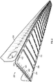
FIG. 3 depicts an embodiment of a flexible carrier. -
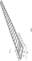
FIG. 4 depicts an embodiment of a flexible carrier having double-sided vacuum grippers installed. -
FIG. 5 depicts an embodiment of a double-sided vacuum gripper. -
FIG. 6 depicts an embodiment of a flexible carrier between a forming platform and a composite part assembly. -
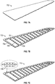
FIG. 7A depicts a slip sheet for forming a flexible carrier. -
FIG. 7B depicts a frame cut from a slip sheet. -
FIG. 7C depicts a flexible carrier formed by adding vacuum grippers to a frame. -
FIG. 8 depicts an embodiment of a composite panel tooling method. - While the disclosure is susceptible to various modifications and alternative forms, specific embodiments have been shown by way of example in the drawings and will be described in detail herein. However, it should be understood that the disclosure is not intended to be limited to the particular forms disclosed. Rather, the intention is to cover all modifications, equivalents and alternatives falling within the scope of the disclosure.
- Referring to
FIG. 1 , an embodiment of a compositepanel tooling system 100 is depicted. Thesystem 100 may include a formingplatform 102 and aflexible carrier 110. The specific example inFIG. 1 is directed toward a tooling system for forming a stabilizer of an aircraft. However, the described systems and methods may be applied to the formation of any composite parts, such as for any vehicles, and is not limited to any particular application. - The forming
platform 102 may have a contouredsurface 104 configured to support a layup of composite material. It may be supported by atruss system 120 that ensures the proper shape of the contoured surface. Thetruss system 120 may also raise the level of the formingplatform 102 to provide workers with ready access to a layup.Various access points 122 may also be positioned within thesupport truss system 120 to provide, among other systems, vacuum access to ensure uniformity throughout the formed part. - The
flexible carrier 110 may be removably disposed on thecontoured surface 104. By flexing, theflexible carrier 110 may conform to the contouredsurface 104 and may be configured to pneumatically grip thecontoured surface 104. For example, theflexible carrier 110 may include at least one double-sided vacuum gripper 402. While one side of the at least one double-sided gripper 402 may grip thecontoured surface 104, the other side may grip a formed and cured part, thereby securing the part to the contouredsurface 104. In practice, theflexible carrier 110 may include many vacuum grippers in order to uniformly hold a part. Further, as depicted inFIG. 1 , theflexible carrier 110 may substantially span the contouredsurface 104 so as to secure the part along its entire length. As used herein, the term "substantially" means that the flexible carrier spans the entirecontoured surface 104 minus a small margin at the edge at which no significant flexing occurs in a formed and cured layup. Theflexible carrier 110 is further described herein. Having individual tools and areas on an assembly floor for post-cure processes, such as inspecting and scanning new parts for defects, may substantially increase the production area footprint for manufacturing composite parts. Theflexible carrier 110 may enable the formingplatform 102 to be reused to hold a composite part during subsequent processes, thereby reducing the overall footprint required for production. - Referring to
FIG. 2 , an embodiment of acomposite part assembly 200 is depicted. Thecomposite part assembly 200 may include acomposite part 204 formed from alayup 202 of composite material. In the example shown inFIG. 2 , thecomposite part 204 may be a lower outer skin of a control surface of an aircraft. Thecomposite part assembly 200 may also include at least oneadditional part 208 attached to thecomposite part 204. For example, the at least oneadditional part 208 may be a stringer, or other lateral structure attached to thecomposite part 204. AlthoughFIG. 2 depicts thecomposite part 204 as being part of an aircraft, the disclosed systems and methods are not limited to aircraft. Other applications are possible. -
FIG. 2 also depicts theflexible carrier 110 removably disposed on asurface 206 of thecomposite part 204. The at least one double-sided vacuum gripper 402 may be configured to secure theflexible carrier 110 against thesurface 206 on one side, while also securing theflexible carrier 110 against the contouredsurface 104 ofFIG. 1 on the other side. - Referring to
FIG. 3 , an embodiment of aflexible carrier 110 is depicted. Theflexible carrier 110 may include aframe 302. Theframe 302 may include a set ofapertures apertures frame 302 may include a pair ofside members 304 and a set ofintercostal members 306 spanning between the pair ofside members 304. The positions of theintercostal members 306 may correspond to predetermined joint locations associated with stringers along a contoured composite part. Theframe 302 may be formed by cutting a single composite slip sheet according to a pattern. Various cutting processes may be used including, but not limited to, a water jet cutting process. - In order to hold a part securely, the set of
apertures multiple apertures 310 defined within the pair ofside members 304 andmultiple apertures 308 defined within the set ofintercostal members 306. The set ofapertures side members 304 and the set ofintercostal members 306. Theframe 302 may substantially span the contoured surface 104 (shown inFIG. 1 ) in order to securely hold a part. - Referring to
FIG. 4 , an embodiment of aflexible carrier 110 is depicted.FIG. 4 also depicted a set of double-sided vacuum grippers 404. Eachvacuum gripper 402 may be deposited within the apertures within theframe 302. The set ofvacuum grippers 404 may be configured to grip surfaces on both sides of theflexible carrier 110 when activated. For example, each double-sided vacuum gripper 402 may be configured to grip the contoured surface 104 (shown inFIG. 1 ) on one side and to grip thesurface 206 of the composite part 204 (shown inFIG. 2 ) on the other side. - Referring to
FIG. 5 , an embodiment of a double-sided vacuum gripper 402 is depicted. The double-sided vacuum gripper 402 may be configured to connect to apneumatic system 520 to induce a vacuum on afirst side 502 of thevacuum gripper 402 for gripping a contoured surface of a layup tool and on asecond side 504 of thevacuum gripper 402 for gripping a surface of a contoured composite part. Aseal 506 may run along a perimeter of thevacuum gripper 402 to generate a vacuum against a surface when thepneumatic system 520 is activated. Achannel 508 within thevacuum gripper 402 may be in fluid communication with aconnective component 510 such as a valve. Thepneumatic system 520 may be connected to theconnective component 510 and, upon activation, may cause a pressure differential to be generated, thereby forming the vacuum when theseal 506 is pressed against a surface. A similar channel may exist on thesecond side 504 of thevacuum gripper 402 and may be in fluid communication with a secondconnective component 522. - During operation, the double-
sided vacuum gripper 402 may create afirst vacuum circuit 512 on thefirst side 502 and asecond vacuum circuit 514 on thesecond side 504. Thefirst vacuum circuit 512 may be isolated from thesecond vacuum circuit 514 so that each of thevacuum circuits - Referring to
FIG. 6 , an embodiment of aflexible carrier 110 is depicted between a formingplatform 102 and acomposite part assembly 200. Thecomposite part assembly 200 is depicted as being transparent in order to show theflexible carrier 110. As shown inFIG. 6 ,positions 612 of theintercostal members 306 of theflexible carrier 110 may correspond to predeterminedjoint locations 614 along the contouredcomposite part 204. Thejoint locations 614 may correspond tojoints 604 between thecomposite part 204 andlateral parts 602 within thecomposite part assembly 200. - By ensuring that the
positions 612 of theintercostal members 306 correspond to the predeterminedjoint locations 614, theflexible carrier 110 may provide support for forming thejoints 604 by holding thecomposite part 204 against the contouredsurface 104 of the formingplatform 102 at the precise location of each of thejoints 604. This may prevent deformation and/or flexing of thecomposite part 204 while thejoints 604 are being created during the manufacturing process. By reducing the deformation and flexing, some post-cure processing and tooling may be eliminated. Further, by using the formingplatform 102 as a support underneath theflexible carrier 110, additional tooling may be eliminated to reduce the tooling footprint.FIGS. 7A-7B illustrate the formation of an embodiment of theflexible carrier 110. Referring toFIG. 7A , aslip sheet 702 is depicted. Theslip sheet 702 may include a carbon composite material and may be a single carbon slip sheet. It may be formed and cured on a contoured surface on which it will later be used as a flexible carrier, such as thecontoured surface 104. In some embodiments, theslip sheet 702 may include a flexible material so as to conform to a contoured surface without being cured to hold any particular shape. - Referring to
FIG. 7B , theslip sheet 702 is depicted after a cutting operation and defines aframe 703. The cutting operation may include a water jet cutting operation performed by a water jet cut tool. Other types of cutters, including mechanical cutters, stamps, templates, etc., may also be used. Theframe 703 may includeside members 704 withintercostal members 706 positioned laterally between theside members 704. Theframe 703 may correspond to theframe 302 ofFIG. 3 . Although theframe 703 includes twoside members 704 and manyintercostal members 706, in other embodiments, depending on the part being manufactured, other configurations are possible. - Referring to
FIG. 7C , double-sided vacuum grippers 708 have been added to theframe 703 to form aflexible carrier 110. For example, the double-sided vacuum grippers 708 may correspond to the double-sided vacuum gripper 402 and may be used to grip surfaces on both sides of theflexible carrier 110. - Referring to
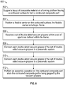
FIG. 8 , a compositepanel tooling method 800 is depicted. Themethod 800 may include supporting a layup of composite material at a forming platform having a contoured surface to form a contoured composite part, at 802. For example, thelayup 202 may be supported at the formingplatform 102 on thecontoured surface 104 to form thecomposite part 204. - The
method 800 may further include positioning a flexible carrier on the contoured surface, the flexible carrier including a frame, at 804. For example, theflexible carrier 110 may be positioned on thecontoured surface 104. - The
method 800 may also include receiving a set of double-sided vacuum grippers within a set of apertures defined within the frame, at 806. For example, the set of double-sided vacuum grippers 404 may be inserted into the set ofapertures frame 302. Themethod 800 may include connecting each double-sided vacuum gripper of the set of double-sided vacuum grippers to a pneumatic system, at 808. For example, each double-sided vacuum gripper 402 may be connected to thepneumatic system 520. - The
method 800 may further include inducing a vacuum on a first side of each vacuum gripper to grip the contoured surface and on a second side of each vacuum gripper to grip a surface of the contoured composite part after the contoured composite part has been formed, at 810. - The
method 800 may also include performing an assembly operation on the contoured composite part while the contoured composite part is being gripped by the vacuum grippers, at 812. For example, thevacuum grippers 402 may hold thecomposite part 204 while an assembly operation, such as drilling pilot holes or attaching additional parts, is performed on thecomposite part 204. - The disclosure comprises the subject matter described in the following clauses:
- Clause 1. A composite panel tooling system comprising: a forming platform having a contoured surface configured to support a layup of composite material to form a contoured composite part; a flexible carrier removably disposed on the contoured surface and comprising a frame, wherein the frame is configured to receive a set of double-sided vacuum grippers within a set of apertures defined within the frame, wherein each double-sided vacuum gripper of the set of double-sided vacuum grippers is configured to connect to a pneumatic system to induce a vacuum on a first side of each double-sided vacuum gripper for gripping the contoured surface and on a second side of each double-sided vacuum gripper for gripping a surface of the contoured composite part after the contoured composite part has been formed.
- Clause 2. The system of clause 1, wherein the frame comprises a pair of side members and a set of intercostal members spanning between the pair of side members.
- Clause 3. The system of clause 2, wherein positions of each intercostal member of the set of intercostal members correspond to predetermined joint locations along the contoured composite part.
- Clause 4. The system of clause 2 or clause 3, wherein the set of apertures includes multiple apertures defined within the pair of side members and within the set of intercostal members.
- Clause 5. The system of any of clauses 2 to 4, wherein the set of apertures are evenly spaced along the pair of side members and the set of intercostal members.
- Clause 6. The system of any preceding clause, wherein the frame substantially spans the contoured surface.
- Clause 7. The system of any preceding clause, wherein each double-sided vacuum gripper of the set of double-sided vacuum grippers includes a first vacuum circuit on the first side and a second vacuum circuit on the second side, wherein the first vacuum circuit is isolated from the second vacuum circuit.
- Clause 8. The system of any preceding clause, wherein the contoured composite part is a part of an aircraft.
- Clause 9. A composite panel tooling method comprising: supporting a layup of composite material at a forming platform having a contoured surface to form a contoured composite part; positioning a flexible carrier on the contoured surface, the flexible carrier including a frame; receiving a set of double-sided vacuum grippers within a set of apertures defined within the frame; connecting each double-sided vacuum gripper of the set of double-sided vacuum grippers to a pneumatic system; inducing a vacuum on a first side of each double-sided vacuum gripper to grip the contoured surface and on a second side of each double-sided vacuum gripper to grip a surface of the contoured composite part after the contoured composite part has been formed.
-
Clause 10. The method of clause 9, wherein the frame comprises a pair of side members and a set of intercostal members spanning between the pair of side members. - Clause 11. The method of
clause 10, further comprising: forming joints at locations along the contoured composite part that correspond to positions of each of the intercostal members of the set of intercostal members. - Clause 12. The method of
clause 10 or clause 11, wherein the set of apertures includes multiple apertures defined within the pair of side members and multiple apertures defined within the set of intercostal members. - Clause 13. The method of any of
clauses 10 to 12, wherein the set of apertures are evenly spaced along the pair of side members and the set of intercostal members. - Clause 14. The method of any of clauses 9 to 13, wherein the frame substantially spans the contoured surface.
- Clause 15. The method of any of clauses 9 to 14, wherein each double-sided vacuum gripper of the set of double-sided vacuum grippers includes a first vacuum circuit on the first side and a second vacuum circuit on the second side, wherein the first vacuum circuit is isolated from the second vacuum circuit.
- Clause 16. The method of any of clauses 9 to 15, wherein the contoured composite part is a part of an aircraft.
- Clause 17. The method of any of clauses 9 to 16, further comprising: performing an assembly operation on the contoured composite part while the contoured composite part is being gripped by the double-sided vacuum grippers.
- Clause 18. A flexible carrier comprising: a frame having a pair of side members and a set of intercostal members spanning between the pair of side members, wherein the frame is configured to receive a set of double-sided vacuum grippers within a set of apertures defined within the frame, wherein each double-sided vacuum gripper of the set of double-sided vacuum grippers is configured to connect to a pneumatic system to induce a vacuum on a first side of each double-sided vacuum gripper for gripping a contoured surface of a forming platform and on a second side of each double-sided vacuum gripper for gripping a surface of a composite part after the composite part has been formed.
- Clause 19. The flexible carrier of clause 18, wherein the frame substantially spans the contoured surface of the forming platform.
- Clause 20. The flexible carrier of clause 18 or clause 19, wherein the frame is cut from a single carbon slip sheet.
- Although various embodiments have been shown and described, the present disclosure is not so limited and will be understood to include all such modifications and variations as would be apparent to one skilled in the art.
Claims (15)
- A composite panel tooling system (100) comprising:a forming platform (102) having a contoured surface (104) configured to support a layup of composite material (202) to form a contoured composite part (204);a flexible carrier (110) removably disposed on the contoured surface (104) and comprising a frame (302), wherein the frame (302) is configured to receive a set of double-sided vacuum grippers (404) within a set of apertures (308, 310) defined within the frame (302), wherein each double-sided vacuum gripper (402) of the set of double-sided vacuum grippers (404) is configured to connect to a pneumatic system (520) to induce a vacuum on a first side (502) of each double-sided vacuum gripper (402) for gripping the contoured surface (104) and on a second side (504) of each double-sided vacuum gripper (402) for gripping a surface (206) of the contoured composite part (204) after the contoured composite part (204) has been formed.
- The system of claim 1, wherein the frame (110) comprises a pair of side members (304) and a set of intercostal members (306) spanning between the pair of side members (304).
- The system of claim 2, wherein positions (612) of each intercostal member of the set of intercostal members (306) correspond to predetermined joint locations (614) along the contoured composite part (204).
- The system of claim 2 or claim 3, wherein the set of apertures (308, 310) includes multiple apertures (308, 310) defined within the pair of side members (304) and within the set of intercostal members (306).
- The system of any of claims 2 to 4, wherein the set of apertures (308, 310) are evenly spaced along the pair of side members (304) and the set of intercostal members (306).
- The system of any of claims 1 to 5, wherein the frame (302) substantially spans the contoured surface (104), and wherein the contoured composite part (204) is a part of an aircraft.
- The system of any of claims 1 to 6, wherein each double-sided vacuum gripper (402) of the set of double-sided vacuum grippers (404) includes a first vacuum circuit on the first side (502) and a second vacuum circuit on the second side (504), wherein the first vacuum circuit is isolated from the second vacuum circuit.
- A composite panel tooling method comprising:supporting a layup (202) of composite material at a forming platform (102) having a contoured surface (104) to form a contoured composite part (204);positioning a flexible carrier (110) on the contoured surface (104), the flexible carrier (110) including a frame (302);receiving a set of double-sided vacuum grippers (404) within a set of apertures (308, 310) defined within the frame (302);connecting each double-sided vacuum gripper (402) of the set of double-sided vacuum grippers (404) to a pneumatic system (520);inducing a vacuum on a first side (502) of each double-sided vacuum gripper (402) to grip the contoured surface (104) and on a second side (504) of each double-sided vacuum gripper to grip a surface (206) of the contoured composite part (204) after the contoured composite part (204) has been formed.
- The method of claim 8, wherein the frame (302) comprises a pair of side members (304) and a set of intercostal members (306) spanning between the pair of side members (304).
- The method of claim 9, further comprising:
forming joints (604) at locations (612) along the contoured composite part (204) that correspond to positions (614) of each of the intercostal members of the set of intercostal members (306). - The method of claim 9 or claim 10, wherein the set of apertures (308, 310) includes multiple apertures (310) defined within the pair of side members and multiple apertures (308) defined within the set of intercostal members (306).
- The method of any of claims 9 to 11, wherein the set of apertures (308, 310) are evenly spaced along the pair of side members (304) and the set of intercostal members (306).
- The method of any of claims 8 to 12, wherein the frame (304) is positioned to substantially span the contoured surface (104), and wherein the contoured composite part (204) is a part of an aircraft.
- The method of any of claims 8 to 13, wherein each double-sided vacuum gripper (402) of the set of double-sided vacuum grippers (404) includes a first vacuum circuit on the first side (502) and a second vacuum circuit on the second side (504), wherein the first vacuum circuit is isolated from the second vacuum circuit.
- The method of any of claims 8 to 14, further comprising:
performing an assembly operation on the contoured composite part (204) while the contoured composite part (204) is being gripped by the double-sided vacuum grippers (402).
Applications Claiming Priority (1)
| Application Number | Priority Date | Filing Date | Title |
|---|---|---|---|
| US16/786,498 US11046532B1 (en) | 2020-02-10 | 2020-02-10 | Flexible dual-sided vacuum plate carrier |
Publications (2)
| Publication Number | Publication Date |
|---|---|
| EP3862172A1 true EP3862172A1 (en) | 2021-08-11 |
| EP3862172B1 EP3862172B1 (en) | 2023-06-21 |
Family
ID=74586739
Family Applications (1)
| Application Number | Title | Priority Date | Filing Date |
|---|---|---|---|
| EP21156019.8A Active EP3862172B1 (en) | 2020-02-10 | 2021-02-09 | Composite panel tooling system and method |
Country Status (3)
| Country | Link |
|---|---|
| US (1) | US11046532B1 (en) |
| EP (1) | EP3862172B1 (en) |
| CN (1) | CN113246491B (en) |
Citations (1)
| Publication number | Priority date | Publication date | Assignee | Title |
|---|---|---|---|---|
| US4571320A (en) * | 1984-10-31 | 1986-02-18 | General Motors Corporation | Method and apparatus for loading and unloading sheet molding compound in and from a press |
Family Cites Families (10)
| Publication number | Priority date | Publication date | Assignee | Title |
|---|---|---|---|---|
| FR2632987B1 (en) * | 1988-06-16 | 1990-10-26 | Robin Francois | METHOD OF AUTOMATED GRIPPING OF TWO ADJACENT CORNERS OF A FLAT LAUNDRY AND MACHINE THEREFOR |
| US5902449A (en) * | 1997-08-15 | 1999-05-11 | Moore; Charles J. | Machine and method for applying pressure sensitive labels |
| US7075084B2 (en) * | 2002-12-20 | 2006-07-11 | The Boeing Company | Ultrasonic thermography inspection method and apparatus |
| CN202498452U (en) * | 2012-02-18 | 2012-10-24 | 沈阳飞机工业(集团)有限公司 | Fixing device of shot blasting parts |
| DE102012102265A1 (en) * | 2012-03-16 | 2013-09-19 | Carlo Sicko | Vacuum gripper kit e.g. vacuum gripper pad for vacuum gripper in wood working industry for gripping glass panes, has foam sheet made of foam material whose strain hardness is reduced by dividing material into sheet between intake openings |
| ITPR20120067A1 (en) * | 2012-10-17 | 2014-04-18 | Lanfranchi Srl | ROTATING SYSTEM FOR THE TRANSFER OF BOTTLES OR CONTAINERS IN GENERAL |
| US10287118B2 (en) * | 2013-12-20 | 2019-05-14 | Tetra Laval Holdings & Finance S.A. | Apparatus and method for feeding carton blanks from a magazine to carriers |
| EP3210882A1 (en) * | 2016-02-08 | 2017-08-30 | Bell Helicopter Textron Inc. | Composite wing structure and methods of manufacture |
| CN206590569U (en) * | 2017-02-28 | 2017-10-27 | 上海道多汽车设备有限公司 | A kind of auto production line two-sided handgrip of top cover buckling plate |
| US10458455B2 (en) * | 2017-12-22 | 2019-10-29 | The Boeing Company | Systems and methods for making and using a fitted cap for applying a shaped sealant shroud to a portion of a fastener |
-
2020
- 2020-02-10 US US16/786,498 patent/US11046532B1/en active Active
- 2020-12-21 CN CN202011517554.0A patent/CN113246491B/en active Active
-
2021
- 2021-02-09 EP EP21156019.8A patent/EP3862172B1/en active Active
Patent Citations (1)
| Publication number | Priority date | Publication date | Assignee | Title |
|---|---|---|---|---|
| US4571320A (en) * | 1984-10-31 | 1986-02-18 | General Motors Corporation | Method and apparatus for loading and unloading sheet molding compound in and from a press |
Also Published As
| Publication number | Publication date |
|---|---|
| CN113246491A (en) | 2021-08-13 |
| US11046532B1 (en) | 2021-06-29 |
| EP3862172B1 (en) | 2023-06-21 |
| CN113246491B (en) | 2025-07-22 |
Similar Documents
| Publication | Publication Date | Title |
|---|---|---|
| US5746553A (en) | Dual purpose lay-up tool | |
| US6012883A (en) | Hybrid lay-up tool | |
| EP2965876B1 (en) | Clamping feet for an end effector | |
| US6170157B1 (en) | Determinant spar assembly | |
| EP0888201B1 (en) | Determinant spar assembly | |
| US8695219B2 (en) | Determinant wing assembly | |
| US20170043529A1 (en) | Airframe production | |
| US11498170B2 (en) | Surface area of fixtures | |
| US11046532B1 (en) | Flexible dual-sided vacuum plate carrier | |
| CA3042602C (en) | Method for co-curing perpendicular stiffeners | |
| US20210094240A1 (en) | Method and apparatus for fabrication of composite tooling | |
| EP3705227B1 (en) | Supporting a contoured sheet of material during machining operations | |
| EP4119446B1 (en) | Method for the assembly of frames in an aircraft shell | |
| US20210095162A1 (en) | Method and apparatus for fabrication of composite tooling | |
| US20170036781A1 (en) | Production of airframe components | |
| CN217965997U (en) | Flexible milling tool for side wall plate | |
| CN219632672U (en) | Girder joint and stringer installation and size assurance frock | |
| CN218860893U (en) | Chemical milling marking-off clamp tool | |
| CA2583586C (en) | Determinant spar assembly | |
| CN211804014U (en) | Inspection tool structure for aircraft antenna array product | |
| US12285920B2 (en) | Method and apparatus for fabrication of composite tooling | |
| CN110561776A (en) | processing technique for molded surface of large-size foam sandwich structure composite material part | |
| Reddy et al. | Design and Manufacture of Aircraft Saddle Fixture for Vertical Stabilizer Assembly Tooling-A Review |
Legal Events
| Date | Code | Title | Description |
|---|---|---|---|
| PUAI | Public reference made under article 153(3) epc to a published international application that has entered the european phase |
Free format text: ORIGINAL CODE: 0009012 |
|
| STAA | Information on the status of an ep patent application or granted ep patent |
Free format text: STATUS: THE APPLICATION HAS BEEN PUBLISHED |
|
| AK | Designated contracting states |
Kind code of ref document: A1 Designated state(s): AL AT BE BG CH CY CZ DE DK EE ES FI FR GB GR HR HU IE IS IT LI LT LU LV MC MK MT NL NO PL PT RO RS SE SI SK SM TR |
|
| STAA | Information on the status of an ep patent application or granted ep patent |
Free format text: STATUS: REQUEST FOR EXAMINATION WAS MADE |
|
| 17P | Request for examination filed |
Effective date: 20210921 |
|
| RBV | Designated contracting states (corrected) |
Designated state(s): AL AT BE BG CH CY CZ DE DK EE ES FI FR GB GR HR HU IE IS IT LI LT LU LV MC MK MT NL NO PL PT RO RS SE SI SK SM TR |
|
| STAA | Information on the status of an ep patent application or granted ep patent |
Free format text: STATUS: EXAMINATION IS IN PROGRESS |
|
| 17Q | First examination report despatched |
Effective date: 20220706 |
|
| GRAP | Despatch of communication of intention to grant a patent |
Free format text: ORIGINAL CODE: EPIDOSNIGR1 |
|
| STAA | Information on the status of an ep patent application or granted ep patent |
Free format text: STATUS: GRANT OF PATENT IS INTENDED |
|
| INTG | Intention to grant announced |
Effective date: 20230113 |
|
| RAP3 | Party data changed (applicant data changed or rights of an application transferred) |
Owner name: THE BOEING COMPANY |
|
| GRAS | Grant fee paid |
Free format text: ORIGINAL CODE: EPIDOSNIGR3 |
|
| GRAA | (expected) grant |
Free format text: ORIGINAL CODE: 0009210 |
|
| STAA | Information on the status of an ep patent application or granted ep patent |
Free format text: STATUS: THE PATENT HAS BEEN GRANTED |
|
| AK | Designated contracting states |
Kind code of ref document: B1 Designated state(s): AL AT BE BG CH CY CZ DE DK EE ES FI FR GB GR HR HU IE IS IT LI LT LU LV MC MK MT NL NO PL PT RO RS SE SI SK SM TR |
|
| REG | Reference to a national code |
Ref country code: CH Ref legal event code: EP |
|
| REG | Reference to a national code |
Ref country code: DE Ref legal event code: R096 Ref document number: 602021002972 Country of ref document: DE |
|
| REG | Reference to a national code |
Ref country code: AT Ref legal event code: REF Ref document number: 1580631 Country of ref document: AT Kind code of ref document: T Effective date: 20230715 |
|
| REG | Reference to a national code |
Ref country code: IE Ref legal event code: FG4D |
|
| P01 | Opt-out of the competence of the unified patent court (upc) registered |
Effective date: 20230704 |
|
| REG | Reference to a national code |
Ref country code: LT Ref legal event code: MG9D |
|
| REG | Reference to a national code |
Ref country code: NL Ref legal event code: MP Effective date: 20230621 |
|
| PG25 | Lapsed in a contracting state [announced via postgrant information from national office to epo] |
Ref country code: SE Free format text: LAPSE BECAUSE OF FAILURE TO SUBMIT A TRANSLATION OF THE DESCRIPTION OR TO PAY THE FEE WITHIN THE PRESCRIBED TIME-LIMIT Effective date: 20230621 Ref country code: NO Free format text: LAPSE BECAUSE OF FAILURE TO SUBMIT A TRANSLATION OF THE DESCRIPTION OR TO PAY THE FEE WITHIN THE PRESCRIBED TIME-LIMIT Effective date: 20230921 |
|
| REG | Reference to a national code |
Ref country code: AT Ref legal event code: MK05 Ref document number: 1580631 Country of ref document: AT Kind code of ref document: T Effective date: 20230621 |
|
| PG25 | Lapsed in a contracting state [announced via postgrant information from national office to epo] |
Ref country code: RS Free format text: LAPSE BECAUSE OF FAILURE TO SUBMIT A TRANSLATION OF THE DESCRIPTION OR TO PAY THE FEE WITHIN THE PRESCRIBED TIME-LIMIT Effective date: 20230621 Ref country code: NL Free format text: LAPSE BECAUSE OF FAILURE TO SUBMIT A TRANSLATION OF THE DESCRIPTION OR TO PAY THE FEE WITHIN THE PRESCRIBED TIME-LIMIT Effective date: 20230621 Ref country code: LV Free format text: LAPSE BECAUSE OF FAILURE TO SUBMIT A TRANSLATION OF THE DESCRIPTION OR TO PAY THE FEE WITHIN THE PRESCRIBED TIME-LIMIT Effective date: 20230621 Ref country code: LT Free format text: LAPSE BECAUSE OF FAILURE TO SUBMIT A TRANSLATION OF THE DESCRIPTION OR TO PAY THE FEE WITHIN THE PRESCRIBED TIME-LIMIT Effective date: 20230621 Ref country code: HR Free format text: LAPSE BECAUSE OF FAILURE TO SUBMIT A TRANSLATION OF THE DESCRIPTION OR TO PAY THE FEE WITHIN THE PRESCRIBED TIME-LIMIT Effective date: 20230621 Ref country code: GR Free format text: LAPSE BECAUSE OF FAILURE TO SUBMIT A TRANSLATION OF THE DESCRIPTION OR TO PAY THE FEE WITHIN THE PRESCRIBED TIME-LIMIT Effective date: 20230922 |
|
| PG25 | Lapsed in a contracting state [announced via postgrant information from national office to epo] |
Ref country code: FI Free format text: LAPSE BECAUSE OF FAILURE TO SUBMIT A TRANSLATION OF THE DESCRIPTION OR TO PAY THE FEE WITHIN THE PRESCRIBED TIME-LIMIT Effective date: 20230621 |
|
| PG25 | Lapsed in a contracting state [announced via postgrant information from national office to epo] |
Ref country code: SK Free format text: LAPSE BECAUSE OF FAILURE TO SUBMIT A TRANSLATION OF THE DESCRIPTION OR TO PAY THE FEE WITHIN THE PRESCRIBED TIME-LIMIT Effective date: 20230621 |
|
| PG25 | Lapsed in a contracting state [announced via postgrant information from national office to epo] |
Ref country code: ES Free format text: LAPSE BECAUSE OF FAILURE TO SUBMIT A TRANSLATION OF THE DESCRIPTION OR TO PAY THE FEE WITHIN THE PRESCRIBED TIME-LIMIT Effective date: 20230621 |
|
| PG25 | Lapsed in a contracting state [announced via postgrant information from national office to epo] |
Ref country code: IS Free format text: LAPSE BECAUSE OF FAILURE TO SUBMIT A TRANSLATION OF THE DESCRIPTION OR TO PAY THE FEE WITHIN THE PRESCRIBED TIME-LIMIT Effective date: 20231021 |
|
| PG25 | Lapsed in a contracting state [announced via postgrant information from national office to epo] |
Ref country code: SM Free format text: LAPSE BECAUSE OF FAILURE TO SUBMIT A TRANSLATION OF THE DESCRIPTION OR TO PAY THE FEE WITHIN THE PRESCRIBED TIME-LIMIT Effective date: 20230621 Ref country code: SK Free format text: LAPSE BECAUSE OF FAILURE TO SUBMIT A TRANSLATION OF THE DESCRIPTION OR TO PAY THE FEE WITHIN THE PRESCRIBED TIME-LIMIT Effective date: 20230621 Ref country code: RO Free format text: LAPSE BECAUSE OF FAILURE TO SUBMIT A TRANSLATION OF THE DESCRIPTION OR TO PAY THE FEE WITHIN THE PRESCRIBED TIME-LIMIT Effective date: 20230621 Ref country code: PT Free format text: LAPSE BECAUSE OF FAILURE TO SUBMIT A TRANSLATION OF THE DESCRIPTION OR TO PAY THE FEE WITHIN THE PRESCRIBED TIME-LIMIT Effective date: 20231023 Ref country code: IS Free format text: LAPSE BECAUSE OF FAILURE TO SUBMIT A TRANSLATION OF THE DESCRIPTION OR TO PAY THE FEE WITHIN THE PRESCRIBED TIME-LIMIT Effective date: 20231021 Ref country code: ES Free format text: LAPSE BECAUSE OF FAILURE TO SUBMIT A TRANSLATION OF THE DESCRIPTION OR TO PAY THE FEE WITHIN THE PRESCRIBED TIME-LIMIT Effective date: 20230621 Ref country code: EE Free format text: LAPSE BECAUSE OF FAILURE TO SUBMIT A TRANSLATION OF THE DESCRIPTION OR TO PAY THE FEE WITHIN THE PRESCRIBED TIME-LIMIT Effective date: 20230621 Ref country code: CZ Free format text: LAPSE BECAUSE OF FAILURE TO SUBMIT A TRANSLATION OF THE DESCRIPTION OR TO PAY THE FEE WITHIN THE PRESCRIBED TIME-LIMIT Effective date: 20230621 Ref country code: AT Free format text: LAPSE BECAUSE OF FAILURE TO SUBMIT A TRANSLATION OF THE DESCRIPTION OR TO PAY THE FEE WITHIN THE PRESCRIBED TIME-LIMIT Effective date: 20230621 |
|
| PG25 | Lapsed in a contracting state [announced via postgrant information from national office to epo] |
Ref country code: PL Free format text: LAPSE BECAUSE OF FAILURE TO SUBMIT A TRANSLATION OF THE DESCRIPTION OR TO PAY THE FEE WITHIN THE PRESCRIBED TIME-LIMIT Effective date: 20230621 |
|
| REG | Reference to a national code |
Ref country code: DE Ref legal event code: R097 Ref document number: 602021002972 Country of ref document: DE |
|
| PLBE | No opposition filed within time limit |
Free format text: ORIGINAL CODE: 0009261 |
|
| STAA | Information on the status of an ep patent application or granted ep patent |
Free format text: STATUS: NO OPPOSITION FILED WITHIN TIME LIMIT |
|
| PG25 | Lapsed in a contracting state [announced via postgrant information from national office to epo] |
Ref country code: DK Free format text: LAPSE BECAUSE OF FAILURE TO SUBMIT A TRANSLATION OF THE DESCRIPTION OR TO PAY THE FEE WITHIN THE PRESCRIBED TIME-LIMIT Effective date: 20230621 |
|
| PG25 | Lapsed in a contracting state [announced via postgrant information from national office to epo] |
Ref country code: SI Free format text: LAPSE BECAUSE OF FAILURE TO SUBMIT A TRANSLATION OF THE DESCRIPTION OR TO PAY THE FEE WITHIN THE PRESCRIBED TIME-LIMIT Effective date: 20230621 |
|
| 26N | No opposition filed |
Effective date: 20240322 |
|
| PG25 | Lapsed in a contracting state [announced via postgrant information from national office to epo] |
Ref country code: SI Free format text: LAPSE BECAUSE OF FAILURE TO SUBMIT A TRANSLATION OF THE DESCRIPTION OR TO PAY THE FEE WITHIN THE PRESCRIBED TIME-LIMIT Effective date: 20230621 Ref country code: IT Free format text: LAPSE BECAUSE OF FAILURE TO SUBMIT A TRANSLATION OF THE DESCRIPTION OR TO PAY THE FEE WITHIN THE PRESCRIBED TIME-LIMIT Effective date: 20230621 |
|
| PG25 | Lapsed in a contracting state [announced via postgrant information from national office to epo] |
Ref country code: MC Free format text: LAPSE BECAUSE OF FAILURE TO SUBMIT A TRANSLATION OF THE DESCRIPTION OR TO PAY THE FEE WITHIN THE PRESCRIBED TIME-LIMIT Effective date: 20230621 |
|
| REG | Reference to a national code |
Ref country code: CH Ref legal event code: PL |
|
| PG25 | Lapsed in a contracting state [announced via postgrant information from national office to epo] |
Ref country code: LU Free format text: LAPSE BECAUSE OF NON-PAYMENT OF DUE FEES Effective date: 20240209 |
|
| PG25 | Lapsed in a contracting state [announced via postgrant information from national office to epo] |
Ref country code: CH Free format text: LAPSE BECAUSE OF NON-PAYMENT OF DUE FEES Effective date: 20240229 |
|
| PG25 | Lapsed in a contracting state [announced via postgrant information from national office to epo] |
Ref country code: LU Free format text: LAPSE BECAUSE OF NON-PAYMENT OF DUE FEES Effective date: 20240209 Ref country code: CH Free format text: LAPSE BECAUSE OF NON-PAYMENT OF DUE FEES Effective date: 20240229 |
|
| PG25 | Lapsed in a contracting state [announced via postgrant information from national office to epo] |
Ref country code: BG Free format text: LAPSE BECAUSE OF FAILURE TO SUBMIT A TRANSLATION OF THE DESCRIPTION OR TO PAY THE FEE WITHIN THE PRESCRIBED TIME-LIMIT Effective date: 20230621 |
|
| PG25 | Lapsed in a contracting state [announced via postgrant information from national office to epo] |
Ref country code: BG Free format text: LAPSE BECAUSE OF FAILURE TO SUBMIT A TRANSLATION OF THE DESCRIPTION OR TO PAY THE FEE WITHIN THE PRESCRIBED TIME-LIMIT Effective date: 20230621 |
|
| REG | Reference to a national code |
Ref country code: BE Ref legal event code: MM Effective date: 20240229 |
|
| PG25 | Lapsed in a contracting state [announced via postgrant information from national office to epo] |
Ref country code: BE Free format text: LAPSE BECAUSE OF NON-PAYMENT OF DUE FEES Effective date: 20240229 |
|
| PG25 | Lapsed in a contracting state [announced via postgrant information from national office to epo] |
Ref country code: IE Free format text: LAPSE BECAUSE OF NON-PAYMENT OF DUE FEES Effective date: 20240209 |
|
| PG25 | Lapsed in a contracting state [announced via postgrant information from national office to epo] |
Ref country code: IE Free format text: LAPSE BECAUSE OF NON-PAYMENT OF DUE FEES Effective date: 20240209 Ref country code: BE Free format text: LAPSE BECAUSE OF NON-PAYMENT OF DUE FEES Effective date: 20240229 |
|
| PG25 | Lapsed in a contracting state [announced via postgrant information from national office to epo] |
Ref country code: CY Free format text: LAPSE BECAUSE OF FAILURE TO SUBMIT A TRANSLATION OF THE DESCRIPTION OR TO PAY THE FEE WITHIN THE PRESCRIBED TIME-LIMIT; INVALID AB INITIO Effective date: 20210209 |
|
| PG25 | Lapsed in a contracting state [announced via postgrant information from national office to epo] |
Ref country code: HU Free format text: LAPSE BECAUSE OF FAILURE TO SUBMIT A TRANSLATION OF THE DESCRIPTION OR TO PAY THE FEE WITHIN THE PRESCRIBED TIME-LIMIT; INVALID AB INITIO Effective date: 20210209 |
|
| PG25 | Lapsed in a contracting state [announced via postgrant information from national office to epo] |
Ref country code: TR Free format text: LAPSE BECAUSE OF FAILURE TO SUBMIT A TRANSLATION OF THE DESCRIPTION OR TO PAY THE FEE WITHIN THE PRESCRIBED TIME-LIMIT Effective date: 20230621 |
|
| PGFP | Annual fee paid to national office [announced via postgrant information from national office to epo] |
Ref country code: GB Payment date: 20260227 Year of fee payment: 6 |
|
| PGFP | Annual fee paid to national office [announced via postgrant information from national office to epo] |
Ref country code: DE Payment date: 20260227 Year of fee payment: 6 |
|
| PGFP | Annual fee paid to national office [announced via postgrant information from national office to epo] |
Ref country code: FR Payment date: 20260225 Year of fee payment: 6 |