EP3862131A1 - Plant for processing products - Google Patents
Plant for processing products Download PDFInfo
- Publication number
- EP3862131A1 EP3862131A1 EP20156202.2A EP20156202A EP3862131A1 EP 3862131 A1 EP3862131 A1 EP 3862131A1 EP 20156202 A EP20156202 A EP 20156202A EP 3862131 A1 EP3862131 A1 EP 3862131A1
- Authority
- EP
- European Patent Office
- Prior art keywords
- plant
- processing
- work area
- products according
- managing products
- Prior art date
- Legal status (The legal status is an assumption and is not a legal conclusion. Google has not performed a legal analysis and makes no representation as to the accuracy of the status listed.)
- Granted
Links
Images




Classifications
-
- B—PERFORMING OPERATIONS; TRANSPORTING
- B23—MACHINE TOOLS; METAL-WORKING NOT OTHERWISE PROVIDED FOR
- B23P—METAL-WORKING NOT OTHERWISE PROVIDED FOR; COMBINED OPERATIONS; UNIVERSAL MACHINE TOOLS
- B23P21/00—Machines for assembling a multiplicity of different parts to compose units, with or without preceding or subsequent working of such parts, e.g. with program control
- B23P21/004—Machines for assembling a multiplicity of different parts to compose units, with or without preceding or subsequent working of such parts, e.g. with program control the units passing two or more work-stations whilst being composed
-
- B—PERFORMING OPERATIONS; TRANSPORTING
- B23—MACHINE TOOLS; METAL-WORKING NOT OTHERWISE PROVIDED FOR
- B23Q—DETAILS, COMPONENTS, OR ACCESSORIES FOR MACHINE TOOLS, e.g. ARRANGEMENTS FOR COPYING OR CONTROLLING; MACHINE TOOLS IN GENERAL CHARACTERISED BY THE CONSTRUCTION OF PARTICULAR DETAILS OR COMPONENTS; COMBINATIONS OR ASSOCIATIONS OF METAL-WORKING MACHINES, NOT DIRECTED TO A PARTICULAR RESULT
- B23Q7/00—Arrangements for handling work specially combined with or arranged in, or specially adapted for use in connection with, machine tools, e.g. for conveying, loading, positioning, discharging, sorting
- B23Q7/14—Arrangements for handling work specially combined with or arranged in, or specially adapted for use in connection with, machine tools, e.g. for conveying, loading, positioning, discharging, sorting co-ordinated in production lines
- B23Q7/1426—Arrangements for handling work specially combined with or arranged in, or specially adapted for use in connection with, machine tools, e.g. for conveying, loading, positioning, discharging, sorting co-ordinated in production lines with work holders not rigidly fixed to the transport devices
-
- Y—GENERAL TAGGING OF NEW TECHNOLOGICAL DEVELOPMENTS; GENERAL TAGGING OF CROSS-SECTIONAL TECHNOLOGIES SPANNING OVER SEVERAL SECTIONS OF THE IPC; TECHNICAL SUBJECTS COVERED BY FORMER USPC CROSS-REFERENCE ART COLLECTIONS [XRACs] AND DIGESTS
- Y02—TECHNOLOGIES OR APPLICATIONS FOR MITIGATION OR ADAPTATION AGAINST CLIMATE CHANGE
- Y02P—CLIMATE CHANGE MITIGATION TECHNOLOGIES IN THE PRODUCTION OR PROCESSING OF GOODS
- Y02P90/00—Enabling technologies with a potential contribution to greenhouse gas [GHG] emissions mitigation
- Y02P90/02—Total factory control, e.g. smart factories, flexible manufacturing systems [FMS] or integrated manufacturing systems [IMS]
Definitions
- the present invention relates to a plant for managing products, which is usable in different sectors and designed for different purposes, for example processing components or storing and handling the products themselves.
- the present invention relates to a highly automated modular plant for managing products, which can be managed by software.
- This system includes a plurality of production cells, each of which is associated with at least one step of the processing process.
- the workpieces are moved inside each cell and are conveyed between one cell and another.
- One object of the present invention is to improve current production plants and generally automatic plants for managing products, so as to overcome the aforesaid limits of the prior art.
- Another object of the present invention is to provide an automatic modular plant for managing products, which is organized in such a manner that excluding one modular work area does not compromise the production flow and introducing a new work area does not involve reconfiguring the plant.
- Another object of the present invention is to provide an automatic modular plant for managing products that is reliable and versatile, that is able to adapt to different production needs.
- Another object of the present invention is to provide an automatic modular plant for managing products, in particular a plant for processing components either in small batches or as single components (one piece flow).
- Another object of the present invention is to provide an automatic modular plant for managing products in which the work of the operators who access the plant is functionally integrated with the automatic production cycle.
- Another object of the present invention is to provide an automatic modular plant for managing products in which the safety of the operators who access the automatic modular plant is ensured.
- Another object of the present invention is to provide an automatic modular plant for managing products in which it is easy to maintain and repair the machines.
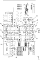
- a modular plant 1 is now disclosed for managing products, which is visible in Fig. 1 .
- the plant 1 can work in a completely automated or partially automated manner, in particular an embodiment will be analyzed of a plant 1 for processing mechanical components in small batches or as single components (one piece flow) by operations of chip removal from a bar.
- the base unit of the modular plant 1 consists of a work area 10 bounded by perimeter walls 12, at least one of which is provided with at least one access 14 for accessing the modular plant 1.
- the walls bound a work area 10 having a square shape.
- virtual alternatives such as photoelectric barriers, laser scanners or a combination of physical and virtual boundaries to bound the work area 10.
- the plant 1 consists of a plurality of work areas 10. In Figs 5-6 , part of the plant 1 is shown consisting of four work areas 10 assembled near one another. Transit corridors 22 are formed between two work areas 10.
- Each work area 10 contains at least one robotic unit 16 for moving and handling mechanical components being processed and objects inherent to processing and communicates with at least one other adjacent work area 10 by at least one automated overhead conveying unit 30, arranged above the separating walls 12 of the work areas 10 and passing above the corridors 22 that are featured between two different work areas 10.
- more than one overhead conveying unit 30 can be installed to connect a plurality of work areas 10 together.
- a processing station 18 for the mechanical components associated operationally with the robotic unit 16.
- Each work area 10 is provided with control panels 24 for the operation of the electric units in the area 10, like the robotic unit 16, the processing station/s 18, the overhead conveying units 30, etc..
- each work area 10 is connected to supply lines 26 for the supply of energy, air, fluids, and data.
- the supply lines 26 are arranged above the work area 10 and follow the perimeter bounded by the walls 12. Other possible solutions for the position of the supply lines 26 are not ruled out.
- the work area 10 can also contain internally storage units that are not shown in the attached figures, which are suitable for containing products being processed or objects inherent to processing.
- the area 10 can also contain movable guards that are suitable for compartmentalizing the work area 10 into different zones. In this manner, the operator accesses the inside of one of the isolated work area 10 in total safety, without stopping the production cycle of the other zones in the same work area 10.
- each overhead conveying unit 30 is supported by supports 28.
- the supports 28 are fixed to the inner floor of each of the work areas 10 that the conveying unit 30 puts in communication. The possibility is not ruled out that the supports 28 are fixed to the ceiling of the structure that houses the plant 1 or to the perimeter walls 12 if they are physical.
- the overhead conveying unit 30 comprises a box-shaped outer casing 31.
- the outer casing 31 is devoid of the summit surface.
- openings 34 and 35 are obtained respectively that are necessary for permitting the robotic unit 16 to handle the mechanical components and the objects inherent to processing conveyed on the overhead conveying unit 30.
- a plurality of conveying plates 38 circulate along the fixed guide 36: the robotic handling units 16 place on the conveying plates 38 the objects to be conveyed and pick the objects to be conveyed therefrom once conveyed to the desired work area 10.
- the conveying plates 38 are connected to anchoring systems, which for the sake of simplicity are not shown in the attached figures, and are moved by one or more dragging groups 39.
- the upper surface 41 of the plate comprises coupling elements 42, 43, 44 designed for receiving each type of object or product that it is necessary to convey from one work area 10 to the other inside the plant 1.
- the coupling elements 42, 43, 44 have to ensure the orientation and stability of the object during the movement step along the fixed guide 36.
- the central seat 42 is shaped to receive the pallets on which the bar pieces are clamped that will have to be processed at the different work areas 10 to provide the final mechanical component.
- a coupling between the conveying plate 38 and the pallet with a component being processed is shown near the opening 34.
- the side seats 43 are on the other hand shaped for receiving other objects inherent to the processing, like work tools.
- the pins 44 on the other hand perform the task of retaining grippers for robots and boxes containing for example scrap, chips, pieces, etc..
- the lower surface 45 of the plate 38 comprises coupling elements 47 for coupling with the fixed guide 36 fitted to a support 46 fixed on the lower surface 45.
- the work area 10 can possibly provide also one exchange position 50 for exchanging objects with the outside, obtained near one of the perimeter walls 12.
- the work area 10 provided with exchange position 50 is shown in Figs 12-15 .
- the exchange position 50 in this particular embodiment, comprises a rotating circular table 51.
- Other possible embodiments of the exchange position 50 are not ruled out, such as for example a linear or loop guide system.
- a first half 52 of the rotating table 51 is located inside the work area 10, whilst the second half 53 is located outside the work area 10.
- the two halves 52, 53 are separated by a separating means 54, which can be of a physical or virtual type.
- the separating means 54 is a plate fixed perpendicularly to the table 51 and isolates the outer space from the work area 10.
- the coupling elements 42, 43, 44 obtained on the conveying plate 38, on which objects can be arranged that are to be taken outside or inside the work area 10.
- the plant 1, consisting of a plurality of work areas 10 as disclosed, can work automatically. Possibly, if necessary or preferred, it is also possible to use workers to perform certain functions such as for example quality control.
- the distance that separates two adjacent work areas has to be such as to create a corridor 22 that is wide enough to permit the transit of operators who access the plant 1 and of corresponding operating tools, such as for example forklift and scaffoldings
- the plant 1 is set up to manufacture mechanical components mainly by chip removal techniques.
- the bar piece 61 to be processed is placed and clamped on a pallet 62, forming the pallet/bar assembly 63.
- the pallets with bar 63 start to circulate from one work area 10 to another, where at the processing stations 18 of the various work areas 10, the bar piece 61 is altered until it takes on the final shape of the component.
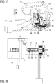
- a centring and locking device 60 is used that is shown in Fig.16-18 .
- the centring and locking device 60 consists of a main body 67 to which a head portion 65 is fitted.
- the centring and locking device 60 is movable along guides 64 and 66 that are perpendicular to one another whilst the head portion 65 is movable along guides 68 fitted to the main body 67.
- a robotic unit 16 deposits the pallet 62 on the end of the head portion 65.
- the centring and locking device 60 approaches a sawing machine 72 where the bar is arranged from which the bar piece 61 will be cut to be clamped on the pallet 62.
- the head portion 65 is arranged on an axis with the bar from which the bar piece 61 will be cut.
- the centring and locking device 60 moves along the guide 64 so as to bring the head portion 65 to the bar from which the bar piece 61 will be cut.
- a screwing system 74 locks the bar and the pallet 62.
- the sawing machine 72 cuts part of the bar 61, on the basis of the type of processing that it will undergo inside the plant 1. Once the cutting has been completed, the centring and locking device 60 moves away from the sawing machine 72 along the guide 64. Lastly, a robotic unit 16 picks the pallet with bar 63, which is sent to the work areas 10 or is placed at a processing station 18 or at an exchange position 50 of the same area.
- the main advantage of the locking and centring device 60 is being able to perform cutting actions when the bar piece 61 is already placed and clamped on the pallet 62.
- the pallets with bar 63, the tools and the objects inherent to the processing are handled by the robotic units 16 in each work area 10.
- the general object can be placed at the processing station 18, at the exchange position 50 (if featured), in warehouses (if featured) or can be placed on the only or on one of the overhead conveying units 30 so that it can be moved to a subsequent work area 10.
- the height of the overhead conveying unit 30 has to be such as to be easily reached by the robotic unit 16 featured in the work areas 10 and to enable operators and instruments to transit with facility through the corridors 22 between the various work areas 10.
- the side surfaces 37 of the overhead conveying unit 30, facing the corridor 22 featured between two adjacent work areas 10 and connected by the overhead conveying unit 30, have a height that is such as not to permit the accidental fall of moving objects onto the overhead conveying unit 30 in the corridor 22 below, so as to avoid possible accidents to the operators moving along the corridors 22 of the plant 1.
- the motion of the conveying plates 38 along the fixed guide 36 is synchronized with the movement of the departure robotic unit 16, in such a way that there is a conveying plate 38 near the opening 34 or 35 ready to receive the object to be conveyed.
- the conveying plate 38 starts to move along the fixed guide 36 to the opposite end of the overhead conveying unit 30.
- the plate 38 stops near the opening 34, 35 opposite the opening where the object has been loaded. Subsequently the object is picked from the robotic unit 16 of the destination work area 10.
- Another function that can be performed by the overhead conveying unit 30 is temporary parking of objects inherent to processing, such as tools, grippers, pallets with bars 63, boxes for collecting chips, scrap etc.
- the walls 12 of the work area mainly perform two functions.
- the first function consists of separating and functionally circumscribing different work areas 10 having different functions, i.e. provided with different processing stations 18.
- the second function consists of protecting operators who access the plant 1, to avoid possible workplace health hazards for operators.
- any malfunction that may harm the health of an operator working at the plant 1 remains, at least initially, circumscribed inside the work area 10. If on the other hand the separating walls are of virtual type, as soon as the operator traverses the separating walls that are of virtual type, the automatic function of the area 10 is interrupted, preventing possible hazards.
- Access 14 to each work area 10 remains shut during the operating step of the robotic unit 16 and can be crossed only when the robotic unit 16 is disabled.
- the functions performed by the machines inside the work area 10 are automated, thus the operator enters through the point of access 14 only during the maintenance step or repair in the event of a machine malfunction.
- the maintenance operator gains access in total safety, once automatic operation of the machines is disabled and there is certainty that there are no severe health hazards for the operator inside.
- the operator can interact with the component being processed, picking other tools and other objects inherent to the processing featured in the work areas 10 by the exchange position 50. Alternatively, the operator can place tools and other objects inherent to the processing inside the work area 10.
- the robotic unit 16 of the work area 10 concerned inserts the pallet with the component being processed 63, which has to be subjected to manual work operations by the operator, or other objects inherent to the processing, that have to be picked by the operator, in the appropriate coupling elements 42, 43, 44 of the inner half 52 of the rotating table 51.
- the table 51 rotates by half a revolution, exposing the inner half 52, with the pallets 63 or other objects inserted, outside the work area 10, whereas the outer half 53 faces inside the work area 10.
- the operator can insert inside the appropriate coupling elements 42,43,44, featured on the outer half 53, pallets with bars 63 or other objects inherent to the processing to be sent inside the work area 10, then rotate by half a revolution the table 51 so as to face the outer half 53 inside the work area 10.
- the expansion of the work areas depends on multiple factors, such as the dimensions of the building in which the plant is assembled and the number of machines featured inside the work area.
- the functional subdivision into work areas and the presence of overhead conveying units results in the presence of a network of corridors that run between the work areas.
- the operators are able to move safely between the corridors, which are separated by the work zones separated by the walls of the work areas. Further, maintenance of the various machines of the plant is simplified and easy to perform.
- the general structure of the plant shown can be used extensively to manage products, not necessarily for processing components by chip removal but also for example for automatic storage of products.
Landscapes
- Engineering & Computer Science (AREA)
- Mechanical Engineering (AREA)
- General Factory Administration (AREA)
- Multi-Process Working Machines And Systems (AREA)
Abstract
Description
- The present invention relates to a plant for managing products, which is usable in different sectors and designed for different purposes, for example processing components or storing and handling the products themselves.
- The present invention relates to a highly automated modular plant for managing products, which can be managed by software.
- Highly automated modular production plants managed by software are known.
- United States patent application
US2004/0255449 shows a reconfigurable integrated production system. - This system includes a plurality of production cells, each of which is associated with at least one step of the processing process.
- The workpieces are moved inside each cell and are conveyed between one cell and another.
- Such systems are often structurally and functionally complicated.
- Further, such systems are bulky and for reasons of safety do not allow processing operators to move between the various cells.
- One object of the present invention is to improve current production plants and generally automatic plants for managing products, so as to overcome the aforesaid limits of the prior art.
- Another object of the present invention is to provide an automatic modular plant for managing products, which is organized in such a manner that excluding one modular work area does not compromise the production flow and introducing a new work area does not involve reconfiguring the plant.
- Another object of the present invention is to provide an automatic modular plant for managing products that is reliable and versatile, that is able to adapt to different production needs.
- Another object of the present invention is to provide an automatic modular plant for managing products, in particular a plant for processing components either in small batches or as single components (one piece flow).
- Another object of the present invention is to provide an automatic modular plant for managing products in which the work of the operators who access the plant is functionally integrated with the automatic production cycle.
- Another object of the present invention is to provide an automatic modular plant for managing products in which the safety of the operators who access the automatic modular plant is ensured.
- Another object of the present invention is to provide an automatic modular plant for managing products in which it is easy to maintain and repair the machines.
- These objects of the invention are achieved by a plant for managing products in accordance with claim 1.
- In order to better understand the invention, a description is given below of a nonlimiting exemplary embodiment thereof, illustrated in the attached drawings in which:
-
Fig. 1 is a plan view of the management plant; -
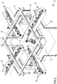
Fig.2 is a perspective view of a modular unit of the management plant; -
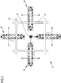
Fig.3 is a plan view of the modular unit inFig.1 ; -
Fig.4 is a perspective view of a plurality of modular units of the management plant; -
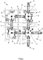
Fig.5 is a plan view of the modular units inFig.3 ; -
Fig.6 is a perspective view of a device featured in the modular unit; -
Fig.7 is a plan view of the device shown inFig.5 ; -
Fig.8 is a detail ofFig.5 ; -
Fig.9 is another detail ofFig.5 ; -
Fig.10 is a perspective view of a component used in the modular unit; -
Fig.11 is a perspective view from another point of view of the component inFig.9 ; -
Fig. 12 is another embodiment of a modular unit of the plant; -
Fig.13 is a plan view of the modular unit inFig.11 ; -
Fig.14 is a detail ofFig. 12 ; -
Fig.15 is a detail ofFig.11 ; -
Fig.16 is a perspective view of a device used in the plant; -
Fig.17 is another view of the device inFig.15 ; -
Fig.18 is a plan view of the device inFig.15 . - With reference to the attached figures, a modular plant 1 is now disclosed for managing products, which is visible in
Fig. 1 . The plant 1 can work in a completely automated or partially automated manner, in particular an embodiment will be analyzed of a plant 1 for processing mechanical components in small batches or as single components (one piece flow) by operations of chip removal from a bar. - The base unit of the modular plant 1 consists of a
work area 10 bounded byperimeter walls 12, at least one of which is provided with at least oneaccess 14 for accessing the modular plant 1. In the embodiment ofFigs 2-3 , the walls bound awork area 10 having a square shape. The possibility is not ruled out of using virtual alternatives such as photoelectric barriers, laser scanners or a combination of physical and virtual boundaries to bound thework area 10. - The plant 1 consists of a plurality of
work areas 10. InFigs 5-6 , part of the plant 1 is shown consisting of fourwork areas 10 assembled near one another.Transit corridors 22 are formed between twowork areas 10. - Each
work area 10 contains at least onerobotic unit 16 for moving and handling mechanical components being processed and objects inherent to processing and communicates with at least one otheradjacent work area 10 by at least one automatedoverhead conveying unit 30, arranged above theseparating walls 12 of thework areas 10 and passing above thecorridors 22 that are featured between twodifferent work areas 10. - Possibly, in the
same work area 10, more than oneoverhead conveying unit 30 can be installed to connect a plurality ofwork areas 10 together. For example, in thework area 10 shown inFigs 2-3 , there are fouroverhead conveying units 30, one for each side of thesquare work area 10, arranged perpendicularly and above thewalls 12 of thearea 10. - Inside the
work area 10, there may also be aprocessing station 18 for the mechanical components associated operationally with therobotic unit 16. - Each
work area 10 is provided withcontrol panels 24 for the operation of the electric units in thearea 10, like therobotic unit 16, the processing station/s 18, theoverhead conveying units 30, etc.. - Further, each
work area 10 is connected tosupply lines 26 for the supply of energy, air, fluids, and data. In the embodiment ofFig.2 , thesupply lines 26 are arranged above thework area 10 and follow the perimeter bounded by thewalls 12. Other possible solutions for the position of thesupply lines 26 are not ruled out. - The
work area 10 can also contain internally storage units that are not shown in the attached figures, which are suitable for containing products being processed or objects inherent to processing. Thearea 10 can also contain movable guards that are suitable for compartmentalizing thework area 10 into different zones. In this manner, the operator accesses the inside of one of theisolated work area 10 in total safety, without stopping the production cycle of the other zones in thesame work area 10. - In
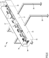
Figs 6-9 , the automatedoverhead conveying unit 30 is shown. Eachoverhead conveying unit 30 is supported bysupports 28. In the embodiment shown in the attached figures, thesupports 28 are fixed to the inner floor of each of thework areas 10 that theconveying unit 30 puts in communication. The possibility is not ruled out that thesupports 28 are fixed to the ceiling of the structure that houses the plant 1 or to theperimeter walls 12 if they are physical. - The
overhead conveying unit 30 comprises a box-shapedouter casing 31. In the shown embodiment, theouter casing 31 is devoid of the summit surface. On the side surfaces 32 and 33 that face thework areas 10 connected by theoverhead conveying unit 30,openings robotic unit 16 to handle the mechanical components and the objects inherent to processing conveyed on theoverhead conveying unit 30. - Inside the cavity defined by the box-shaped
casing 31, there is a fixedguide 36, which, in the embodiment shown, bounds a circuit having an oval shape. The possibility of usingguides 36 having a different shape is not ruled out. - A plurality of conveying
plates 38 circulate along the fixed guide 36: therobotic handling units 16 place on the conveyingplates 38 the objects to be conveyed and pick the objects to be conveyed therefrom once conveyed to the desiredwork area 10. The conveyingplates 38 are connected to anchoring systems, which for the sake of simplicity are not shown in the attached figures, and are moved by one ormore dragging groups 39. - One embodiment of the conveying
plates 38 is shown inFigs 10-11 . Theupper surface 41 of the plate comprisescoupling elements work area 10 to the other inside the plant 1. Thecoupling elements guide 36. - The
central seat 42 is shaped to receive the pallets on which the bar pieces are clamped that will have to be processed at thedifferent work areas 10 to provide the final mechanical component. InFig. 9 , a coupling between the conveyingplate 38 and the pallet with a component being processed is shown near theopening 34. The side seats 43 are on the other hand shaped for receiving other objects inherent to the processing, like work tools. Thepins 44 on the other hand perform the task of retaining grippers for robots and boxes containing for example scrap, chips, pieces, etc.. - The
lower surface 45 of theplate 38 comprisescoupling elements 47 for coupling with the fixedguide 36 fitted to asupport 46 fixed on thelower surface 45. In the embodiment shown inFig. 11 , there are fourcoupling elements 47 of cylindrical shape on whichannular grooves 48 are obtained that are suitable for coming into contact with the side portions of the fixedguide 36. Owing to thecoupling elements 47, theplate 38 is maintained stably in position whilst it is moved by the dragginggroups 39 along the fixedguide 36, so as to ensure correct conveying of the mechanical components or of the objects inherent to the processing. - The
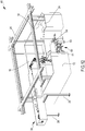
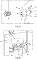
work area 10 can possibly provide also oneexchange position 50 for exchanging objects with the outside, obtained near one of theperimeter walls 12. Thework area 10 provided withexchange position 50 is shown inFigs 12-15 . Theexchange position 50, in this particular embodiment, comprises a rotating circular table 51. Other possible embodiments of theexchange position 50 are not ruled out, such as for example a linear or loop guide system. - A
first half 52 of the rotating table 51 is located inside thework area 10, whilst thesecond half 53 is located outside thework area 10. The twohalves Figs 12-15 , the separating means 54 is a plate fixed perpendicularly to the table 51 and isolates the outer space from thework area 10. On the table 51, there are thesame coupling elements plate 38, on which objects can be arranged that are to be taken outside or inside thework area 10. - The plant 1, consisting of a plurality of
work areas 10 as disclosed, can work automatically. Possibly, if necessary or preferred, it is also possible to use workers to perform certain functions such as for example quality control. - The distance that separates two adjacent work areas has to be such as to create a
corridor 22 that is wide enough to permit the transit of operators who access the plant 1 and of corresponding operating tools, such as for example forklift and scaffoldings - In the disclosed embodiment, the plant 1 is set up to manufacture mechanical components mainly by chip removal techniques. The
bar piece 61 to be processed is placed and clamped on apallet 62, forming the pallet/bar assembly 63. The pallets withbar 63 start to circulate from onework area 10 to another, where at theprocessing stations 18 of thevarious work areas 10, thebar piece 61 is altered until it takes on the final shape of the component. - In order to centre, place and clamp the
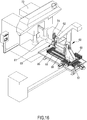
bar piece 61 on the pallet, a centring and lockingdevice 60 is used that is shown inFig.16-18 . The centring and lockingdevice 60 consists of amain body 67 to which ahead portion 65 is fitted. The centring and lockingdevice 60 is movable along guides 64 and 66 that are perpendicular to one another whilst thehead portion 65 is movable along guides 68 fitted to themain body 67. - Initially, a
robotic unit 16 deposits thepallet 62 on the end of thehead portion 65. The centring and lockingdevice 60 approaches a sawingmachine 72 where the bar is arranged from which thebar piece 61 will be cut to be clamped on thepallet 62. Through coordinated movements along theguides head portion 65 is arranged on an axis with the bar from which thebar piece 61 will be cut. Subsequently, the centring and lockingdevice 60 moves along theguide 64 so as to bring thehead portion 65 to the bar from which thebar piece 61 will be cut. Once the bar and thepallet 62 are in contact, a screwingsystem 74 locks the bar and thepallet 62. After locking, the sawingmachine 72 cuts part of thebar 61, on the basis of the type of processing that it will undergo inside the plant 1. Once the cutting has been completed, the centring and lockingdevice 60 moves away from the sawingmachine 72 along theguide 64. Lastly, arobotic unit 16 picks the pallet withbar 63, which is sent to thework areas 10 or is placed at aprocessing station 18 or at anexchange position 50 of the same area. - The main advantage of the locking and
centring device 60 is being able to perform cutting actions when thebar piece 61 is already placed and clamped on thepallet 62. - The pallets with
bar 63, the tools and the objects inherent to the processing are handled by therobotic units 16 in eachwork area 10. - Once the general object has been picked , it can be placed at the
processing station 18, at the exchange position 50 (if featured), in warehouses (if featured) or can be placed on the only or on one of theoverhead conveying units 30 so that it can be moved to asubsequent work area 10. - The height of the
overhead conveying unit 30 has to be such as to be easily reached by therobotic unit 16 featured in thework areas 10 and to enable operators and instruments to transit with facility through thecorridors 22 between thevarious work areas 10. - The side surfaces 37 of the
overhead conveying unit 30, facing thecorridor 22 featured between twoadjacent work areas 10 and connected by theoverhead conveying unit 30, have a height that is such as not to permit the accidental fall of moving objects onto theoverhead conveying unit 30 in thecorridor 22 below, so as to avoid possible accidents to the operators moving along thecorridors 22 of the plant 1. - The motion of the conveying
plates 38 along the fixedguide 36 is synchronized with the movement of the departurerobotic unit 16, in such a way that there is a conveyingplate 38 near theopening relative coupling element plate 38 starts to move along the fixedguide 36 to the opposite end of theoverhead conveying unit 30. Theplate 38 stops near theopening robotic unit 16 of thedestination work area 10. - Another function that can be performed by the
overhead conveying unit 30 is temporary parking of objects inherent to processing, such as tools, grippers, pallets withbars 63, boxes for collecting chips, scrap etc. - The
walls 12 of the work area mainly perform two functions. The first function consists of separating and functionally circumscribingdifferent work areas 10 having different functions, i.e. provided withdifferent processing stations 18. The second function consists of protecting operators who access the plant 1, to avoid possible workplace health hazards for operators. - Owing to the
walls 12, if they are physical barriers, any malfunction that may harm the health of an operator working at the plant 1 remains, at least initially, circumscribed inside thework area 10. If on the other hand the separating walls are of virtual type, as soon as the operator traverses the separating walls that are of virtual type, the automatic function of thearea 10 is interrupted, preventing possible hazards. -
Access 14 to eachwork area 10 remains shut during the operating step of therobotic unit 16 and can be crossed only when therobotic unit 16 is disabled. The functions performed by the machines inside thework area 10 are automated, thus the operator enters through the point ofaccess 14 only during the maintenance step or repair in the event of a machine malfunction. The maintenance operator gains access in total safety, once automatic operation of the machines is disabled and there is certainty that there are no severe health hazards for the operator inside. - The operator can interact with the component being processed, picking other tools and other objects inherent to the processing featured in the
work areas 10 by theexchange position 50. Alternatively, the operator can place tools and other objects inherent to the processing inside thework area 10. - The
robotic unit 16 of thework area 10 concerned inserts the pallet with the component being processed 63, which has to be subjected to manual work operations by the operator, or other objects inherent to the processing, that have to be picked by the operator, in theappropriate coupling elements inner half 52 of the rotating table 51. - Through a command of the operator, the table 51 rotates by half a revolution, exposing the
inner half 52, with thepallets 63 or other objects inserted, outside thework area 10, whereas theouter half 53 faces inside thework area 10. - Alternatively, the operator can insert inside the
appropriate coupling elements outer half 53, pallets withbars 63 or other objects inherent to the processing to be sent inside thework area 10, then rotate by half a revolution the table 51 so as to face theouter half 53 inside thework area 10. - There are no limitations to the shape and dimensions of the work areas provided that they are functionally integrated inside the plant and ensure safety and convenience for the operator if provided inside the plant.
- The expansion of the work areas depends on multiple factors, such as the dimensions of the building in which the plant is assembled and the number of machines featured inside the work area.
- The possibility is not ruled out of associating with the same work area multiple processing stations, which are operationally associated with multiple robot units.
- Owing to the plant as disclosed, the limits of the prior art have been overcome. The modular nature of the work areas enables automatic and at the same time flexible processing plants to be devised that are thus adaptable to the quantity of processing tasks necessary for obtaining the final mechanical component.
- The functional subdivision into work areas and the presence of overhead conveying units results in the presence of a network of corridors that run between the work areas. The operators are able to move safely between the corridors, which are separated by the work zones separated by the walls of the work areas. Further, maintenance of the various machines of the plant is simplified and easy to perform.
- The general structure of the plant shown can be used extensively to manage products, not necessarily for processing components by chip removal but also for example for automatic storage of products.
Claims (14)
- Plant (1) for managing products, comprising a plurality of work areas (10), each bounded by perimeter walls (12), each work area (10) comprising at least one robotic unit (16) for moving and handling the products, and wherein the work areas (10) are connected together by at least one overhead conveying unit (30) for conveying products from one work area (10) to another.
- Plant (1) for managing products according to claim 1, intended for the processing of components and objects inherent to processing, wherein the work area (10) comprises at least one processing station (18) of the components that is associated operationally with the robotic unit (16), wherein a plurality of pallets (62) is featured that are suitable for supporting components being processed, configured for being handled by the robotic units (16), so as to provide support to the component inside a work area (10), during conveying between one work area (10) and another and in the processing station (18).
- Plant (1) for managing products according to claim 1 or 2, comprising one or more corridors (22) interposed between the perimeter walls (12) of the work areas (10).
- Plant (1) for managing products according to claim 3, wherein the overhead conveying unit (30) that connects two adjacent work areas (10) extends above the perimeter walls (12) and above the corridor (22) therebetween.
- Plant (1) for managing products according to any preceding claim, wherein the overhead conveying unit (30) is supported by lower and/or upper supports (28) at the work areas (10) that the unit (30) put in communication.
- Plant (1) for managing products according to any preceding claim, wherein the overhead conveying unit (30) comprises an outer casing (31), provided with openings (34, 35) obtained on the side surfaces (32, 33) facing the work areas (10) and provided with a fixed guide (36) fitted in the cavity formed by the outer casing (31) on which a plurality of conveying plates (38) move.
- Plant (1) for managing products according to claim 6, wherein on the upper surface (41) of the conveying plate (38) coupling elements (42 43, 44) are obtained that are suitable for receiving pallets (63) with components being processed and other objects inherent to processing that it is necessary to convey from one work area (10) to the other inside the processing plant (1).
- Plant (1) for managing products according to claim 6 or 7, wherein on the lower surface (45) coupling elements (47) are provided on which grooves (48) are obtained that are suitable for coupling with the edges of the fixed guide (36), in order to maintain in equilibrium the conveying plates (38) moving on the fixed guide (36).
- Plant (1) for managing products according to any preceding claim, wherein the work area (10) comprises at least one exchange position (50) obtained in the perimeter walls (12) to enable components or other objects inherent to processing to be moved outside and/or inside the area (10).
- Plant (1) for managing products according to claim 9, wherein the exchange position (50) comprises a rotating circular table (51), on which coupling seats are obtained (42, 43, 44) to receive pallets (63) with components being processed and other objects inherent to processing, and a separating wall (54) that divides the table (51) into two parts (52, 53) and separates the work area (10) from the outside environment.
- Plant (1) for managing products according to claim 2, wherein the processing station (18) comprises a centring and locking device (60) for centring and locking an unprocessed processing component (61) on a pallet (62) and a device (72) for initial processing of the unprocessed processing component (61).
- Plant (1) for managing products according to claim 11, wherein the centring and locking device (60) comprises a main body (67), which is movable along guides (64,66) that are perpendicular to one another, wherein the main body (67) is provided with a head portion (65) to which the pallet is fitted (62), which is movable along guides (68) fitted to the main body, wherein the centring and locking device (60) moves along the guides (64,66,68) to align and place the pallet (62) fitted to the head portion (65) in contact with the unprocessed processing component (61).
- Plant (1) for managing products according to claim 11 or 12, wherein the pallet (62) and unprocessed processing component (61) are locked together by a coupling device (74) at the moment of contact between the unprocessed processing component (61) and the pallet (62), for subsequent processing of the unprocessed processing component (61) by the initial processing device (72).
- Plant (1) for managing products according to any preceding claim, wherein the walls (12, 54) are formed by non-physical virtual barriers, for example photoelectric barriers.
Priority Applications (5)
| Application Number | Priority Date | Filing Date | Title |
|---|---|---|---|
| EP20156202.2A EP3862131B1 (en) | 2020-02-07 | 2020-02-07 | Plant for processing products |
| ES20156202T ES3003285T3 (en) | 2020-02-07 | 2020-02-07 | Plant for processing products |
| PCT/IB2021/050961 WO2021156819A1 (en) | 2020-02-07 | 2021-02-05 | Plant for processing products |
| US17/797,757 US11980981B2 (en) | 2020-02-07 | 2021-02-05 | Plant for processing products |
| CN202180013060.5A CN115052709B (en) | 2020-02-07 | 2021-02-05 | Workshop for product processing |
Applications Claiming Priority (1)
| Application Number | Priority Date | Filing Date | Title |
|---|---|---|---|
| EP20156202.2A EP3862131B1 (en) | 2020-02-07 | 2020-02-07 | Plant for processing products |
Publications (3)
| Publication Number | Publication Date |
|---|---|
| EP3862131A1 true EP3862131A1 (en) | 2021-08-11 |
| EP3862131B1 EP3862131B1 (en) | 2024-10-30 |
| EP3862131C0 EP3862131C0 (en) | 2024-10-30 |
Family
ID=70108017
Family Applications (1)
| Application Number | Title | Priority Date | Filing Date |
|---|---|---|---|
| EP20156202.2A Active EP3862131B1 (en) | 2020-02-07 | 2020-02-07 | Plant for processing products |
Country Status (5)
| Country | Link |
|---|---|
| US (1) | US11980981B2 (en) |
| EP (1) | EP3862131B1 (en) |
| CN (1) | CN115052709B (en) |
| ES (1) | ES3003285T3 (en) |
| WO (1) | WO2021156819A1 (en) |
Cited By (1)
| Publication number | Priority date | Publication date | Assignee | Title |
|---|---|---|---|---|
| WO2026027032A1 (en) * | 2024-07-29 | 2026-02-05 | Mikron Switzerland AG, Zweigniederlassung Agno, Machining | Piece-holding module, and feeding apparatus comprising the piece-holding module, for feeding a plurality of machining stations |
Citations (8)
| Publication number | Priority date | Publication date | Assignee | Title |
|---|---|---|---|---|
| JPH03136738A (en) * | 1989-10-23 | 1991-06-11 | Brother Ind Ltd | Pallet positioning clamp device |
| DE19840363A1 (en) * | 1998-09-04 | 2000-03-09 | Heron Sondermaschinen Und Steu | Workpiece carrier for a transfer system has carrier plate with through aperture(s) or opening(s) that can be of any shape with carrier functional parts arranged around through opening |
| US20040255449A1 (en) | 2003-06-19 | 2004-12-23 | Yoram Koren | Integrated reconfigurable manufacturing system |
| EP2045628A1 (en) * | 2007-10-01 | 2009-04-08 | REER S.p.A. | Photoelectric barrier |
| DE102007047279A1 (en) * | 2007-10-02 | 2009-04-09 | Wilhelm Karmann Gmbh | Production system for production of e.g. driving cabs of lorry, has control device controlling processing modules and transport system and generating operating information dependent on actual status of processing steps in processing modules |
| JP2009274159A (en) * | 2008-05-13 | 2009-11-26 | Toyota Motor Corp | Parts supply device |
| DE202015100782U1 (en) * | 2015-02-19 | 2016-05-20 | Kuka Systems Gmbh | manufacturing plant |
| US20180029178A1 (en) * | 2015-02-19 | 2018-02-01 | Kuka Systems Gmbh | Production Plant, Production Device And Production Method |
Family Cites Families (18)
| Publication number | Priority date | Publication date | Assignee | Title |
|---|---|---|---|---|
| US2750897A (en) * | 1956-06-19 | Loading and unloading apparatus | ||
| GB880744A (en) * | 1959-03-13 | 1961-10-25 | Fmc Corp | Apparatus for sorting articles |
| US3348285A (en) * | 1964-11-06 | 1967-10-24 | Delta Ass Ind Corp | Production line |
| US3708051A (en) * | 1971-03-26 | 1973-01-02 | Standard Tool & Mfg Co | Control mechanism for advancing and locating pallets |
| US4094104A (en) * | 1976-10-07 | 1978-06-13 | Synergetics, Inc. | Finishing machine |
| US4487309A (en) * | 1982-01-07 | 1984-12-11 | Dorner Mfg. Corp. | Conveyor system |
| US4890725A (en) * | 1984-03-06 | 1990-01-02 | Asm Fico Tooling B.V. | Automatic continuously cycleable molding system and method |
| US4877387A (en) * | 1984-03-06 | 1989-10-31 | Asm Fico Tooling, B.V. | Automatic continuously cycleable molding system |
| US4575328A (en) * | 1984-03-06 | 1986-03-11 | Asm Fico Tooling, B.V. | Automatic continuously cycleable molding apparatus |
| DE3536015C2 (en) * | 1984-10-16 | 1994-06-23 | Volkswagen Ag | Manufacturing station for different types of motor vehicle bodies |
| US4938334A (en) * | 1988-06-15 | 1990-07-03 | Ps Group, Inc. | Workpiece transport system |
| KR100286123B1 (en) * | 1997-08-28 | 2001-04-16 | 하나와 요시카즈 | Body side assembly of the vehicle |
| JP2002274451A (en) * | 2001-03-21 | 2002-09-25 | Nissan Motor Co Ltd | Body assembly equipment |
| US7490710B1 (en) * | 2006-08-19 | 2009-02-17 | Wes-Tech Automation Solutions, Llc | Flexible manufacturing system having modular work stations |
| CN105083976B (en) * | 2014-05-14 | 2018-02-06 | 泰科电子(上海)有限公司 | Electronic equipment production system |
| US9815155B2 (en) * | 2015-03-31 | 2017-11-14 | GM Global Technology Operations LLC | Reconfigurable assembly work station |
| JP7052372B2 (en) * | 2018-01-22 | 2022-04-12 | 日本電気株式会社 | Transport equipment, processing unit, processing method, and program |
| US10948905B2 (en) * | 2018-06-11 | 2021-03-16 | Middlesex Industries, SA. | High volume autonomous material handling system to improve IC factory throughput and cycle time |
-
2020
- 2020-02-07 EP EP20156202.2A patent/EP3862131B1/en active Active
- 2020-02-07 ES ES20156202T patent/ES3003285T3/en active Active
-
2021
- 2021-02-05 US US17/797,757 patent/US11980981B2/en active Active
- 2021-02-05 WO PCT/IB2021/050961 patent/WO2021156819A1/en not_active Ceased
- 2021-02-05 CN CN202180013060.5A patent/CN115052709B/en active Active
Patent Citations (8)
| Publication number | Priority date | Publication date | Assignee | Title |
|---|---|---|---|---|
| JPH03136738A (en) * | 1989-10-23 | 1991-06-11 | Brother Ind Ltd | Pallet positioning clamp device |
| DE19840363A1 (en) * | 1998-09-04 | 2000-03-09 | Heron Sondermaschinen Und Steu | Workpiece carrier for a transfer system has carrier plate with through aperture(s) or opening(s) that can be of any shape with carrier functional parts arranged around through opening |
| US20040255449A1 (en) | 2003-06-19 | 2004-12-23 | Yoram Koren | Integrated reconfigurable manufacturing system |
| EP2045628A1 (en) * | 2007-10-01 | 2009-04-08 | REER S.p.A. | Photoelectric barrier |
| DE102007047279A1 (en) * | 2007-10-02 | 2009-04-09 | Wilhelm Karmann Gmbh | Production system for production of e.g. driving cabs of lorry, has control device controlling processing modules and transport system and generating operating information dependent on actual status of processing steps in processing modules |
| JP2009274159A (en) * | 2008-05-13 | 2009-11-26 | Toyota Motor Corp | Parts supply device |
| DE202015100782U1 (en) * | 2015-02-19 | 2016-05-20 | Kuka Systems Gmbh | manufacturing plant |
| US20180029178A1 (en) * | 2015-02-19 | 2018-02-01 | Kuka Systems Gmbh | Production Plant, Production Device And Production Method |
Cited By (1)
| Publication number | Priority date | Publication date | Assignee | Title |
|---|---|---|---|---|
| WO2026027032A1 (en) * | 2024-07-29 | 2026-02-05 | Mikron Switzerland AG, Zweigniederlassung Agno, Machining | Piece-holding module, and feeding apparatus comprising the piece-holding module, for feeding a plurality of machining stations |
Also Published As
| Publication number | Publication date |
|---|---|
| US20230073954A1 (en) | 2023-03-09 |
| EP3862131B1 (en) | 2024-10-30 |
| WO2021156819A1 (en) | 2021-08-12 |
| CN115052709A (en) | 2022-09-13 |
| CN115052709B (en) | 2024-09-27 |
| EP3862131C0 (en) | 2024-10-30 |
| ES3003285T3 (en) | 2025-03-10 |
| US11980981B2 (en) | 2024-05-14 |
Similar Documents
| Publication | Publication Date | Title |
|---|---|---|
| CN110773449B (en) | A panel custom furniture sorting system and process | |
| US6745454B1 (en) | Flexible manufacturing and workpiece transfer system | |
| CN106042065B (en) | Plate dividing apparatus and method for dividing plate-like workpieces | |
| WO2020028822A1 (en) | Automated decant system | |
| CN109843503B (en) | Conveying equipment, control device thereof and loading and unloading method of material processing unit | |
| CN209578932U (en) | A kind of tool-changing mechanical arm and tool changing device | |
| US4773523A (en) | Method for automated handling of materials such as automotive parts and system utilizing same | |
| CN112024915B (en) | Disc part processing production line | |
| CN110695747B (en) | Intelligent processing production line and processing technology for tungsten-molybdenum parts | |
| Edmondson et al. | Generic flexible assembly system design | |
| KR20170141139A (en) | Handling apparatus for use at a machine tool | |
| US11980981B2 (en) | Plant for processing products | |
| US20250235971A1 (en) | Combined transfer and storage device and manufacturing line for machining | |
| JP7198864B2 (en) | Conveyor and system for processing workpieces | |
| IT202000028304A1 (en) | SYSTEM FOR THE VARIATION OF THE SURFACE OF THE UNLOADING STATION OF A MACHINE FOR THE PROCESSING OF PIECES AND METHOD OF OPERATION OF THE SYSTEM ITSELF. | |
| JP2005008409A (en) | Automatic loading and unloading system for green tire loading pallets | |
| US20020151420A1 (en) | Worktable Apparatus | |
| US20230405659A1 (en) | Fully automated sheet metal bending cell | |
| CN115740630B (en) | High-end full-automatic robot processing equipment | |
| EP1029631B1 (en) | Loading station with sluice | |
| US6644640B1 (en) | Quick connect/disconnect workpiece transfer unit | |
| CN110650907B (en) | Device for temporarily storing plate-shaped workpieces | |
| IT202000007903A1 (en) | MULTI-TOOL SOCKET HEAD FOR A SORTING EQUIPMENT | |
| EP3676198B1 (en) | Method, transport device and system for material handling | |
| CN121403076B (en) | Intelligent boring and milling production line for large thin-wall shell and operation method |
Legal Events
| Date | Code | Title | Description |
|---|---|---|---|
| PUAI | Public reference made under article 153(3) epc to a published international application that has entered the european phase |
Free format text: ORIGINAL CODE: 0009012 |
|
| STAA | Information on the status of an ep patent application or granted ep patent |
Free format text: STATUS: THE APPLICATION HAS BEEN PUBLISHED |
|
| AK | Designated contracting states |
Kind code of ref document: A1 Designated state(s): AL AT BE BG CH CY CZ DE DK EE ES FI FR GB GR HR HU IE IS IT LI LT LU LV MC MK MT NL NO PL PT RO RS SE SI SK SM TR |
|
| STAA | Information on the status of an ep patent application or granted ep patent |
Free format text: STATUS: REQUEST FOR EXAMINATION WAS MADE |
|
| 17P | Request for examination filed |
Effective date: 20220211 |
|
| RBV | Designated contracting states (corrected) |
Designated state(s): AL AT BE BG CH CY CZ DE DK EE ES FI FR GB GR HR HU IE IS IT LI LT LU LV MC MK MT NL NO PL PT RO RS SE SI SK SM TR |
|
| GRAP | Despatch of communication of intention to grant a patent |
Free format text: ORIGINAL CODE: EPIDOSNIGR1 |
|
| STAA | Information on the status of an ep patent application or granted ep patent |
Free format text: STATUS: GRANT OF PATENT IS INTENDED |
|
| INTG | Intention to grant announced |
Effective date: 20240115 |
|
| GRAS | Grant fee paid |
Free format text: ORIGINAL CODE: EPIDOSNIGR3 |
|
| GRAJ | Information related to disapproval of communication of intention to grant by the applicant or resumption of examination proceedings by the epo deleted |
Free format text: ORIGINAL CODE: EPIDOSDIGR1 |
|
| GRAL | Information related to payment of fee for publishing/printing deleted |
Free format text: ORIGINAL CODE: EPIDOSDIGR3 |
|
| STAA | Information on the status of an ep patent application or granted ep patent |
Free format text: STATUS: REQUEST FOR EXAMINATION WAS MADE |
|
| INTC | Intention to grant announced (deleted) | ||
| GRAP | Despatch of communication of intention to grant a patent |
Free format text: ORIGINAL CODE: EPIDOSNIGR1 |
|
| STAA | Information on the status of an ep patent application or granted ep patent |
Free format text: STATUS: GRANT OF PATENT IS INTENDED |
|
| INTG | Intention to grant announced |
Effective date: 20240816 |
|
| GRAA | (expected) grant |
Free format text: ORIGINAL CODE: 0009210 |
|
| STAA | Information on the status of an ep patent application or granted ep patent |
Free format text: STATUS: THE PATENT HAS BEEN GRANTED |
|
| AK | Designated contracting states |
Kind code of ref document: B1 Designated state(s): AL AT BE BG CH CY CZ DE DK EE ES FI FR GB GR HR HU IE IS IT LI LT LU LV MC MK MT NL NO PL PT RO RS SE SI SK SM TR |
|
| REG | Reference to a national code |
Ref country code: GB Ref legal event code: FG4D |
|
| REG | Reference to a national code |
Ref country code: CH Ref legal event code: EP |
|
| REG | Reference to a national code |
Ref country code: IE Ref legal event code: FG4D |
|
| REG | Reference to a national code |
Ref country code: DE Ref legal event code: R096 Ref document number: 602020040134 Country of ref document: DE |
|
| U01 | Request for unitary effect filed |
Effective date: 20241120 |
|
| U07 | Unitary effect registered |
Designated state(s): AT BE BG DE DK EE FI FR IT LT LU LV MT NL PT RO SE SI Effective date: 20241202 |
|
| REG | Reference to a national code |
Ref country code: ES Ref legal event code: FG2A Ref document number: 3003285 Country of ref document: ES Kind code of ref document: T3 Effective date: 20250310 |
|
| U20 | Renewal fee for the european patent with unitary effect paid |
Year of fee payment: 6 Effective date: 20250228 |
|
| PG25 | Lapsed in a contracting state [announced via postgrant information from national office to epo] |
Ref country code: HR Free format text: LAPSE BECAUSE OF FAILURE TO SUBMIT A TRANSLATION OF THE DESCRIPTION OR TO PAY THE FEE WITHIN THE PRESCRIBED TIME-LIMIT Effective date: 20241030 Ref country code: IS Free format text: LAPSE BECAUSE OF FAILURE TO SUBMIT A TRANSLATION OF THE DESCRIPTION OR TO PAY THE FEE WITHIN THE PRESCRIBED TIME-LIMIT Effective date: 20250228 |
|
| PG25 | Lapsed in a contracting state [announced via postgrant information from national office to epo] |
Ref country code: NO Free format text: LAPSE BECAUSE OF FAILURE TO SUBMIT A TRANSLATION OF THE DESCRIPTION OR TO PAY THE FEE WITHIN THE PRESCRIBED TIME-LIMIT Effective date: 20250130 |
|
| PG25 | Lapsed in a contracting state [announced via postgrant information from national office to epo] |
Ref country code: GR Free format text: LAPSE BECAUSE OF FAILURE TO SUBMIT A TRANSLATION OF THE DESCRIPTION OR TO PAY THE FEE WITHIN THE PRESCRIBED TIME-LIMIT Effective date: 20250131 |
|
| PG25 | Lapsed in a contracting state [announced via postgrant information from national office to epo] |
Ref country code: PL Free format text: LAPSE BECAUSE OF FAILURE TO SUBMIT A TRANSLATION OF THE DESCRIPTION OR TO PAY THE FEE WITHIN THE PRESCRIBED TIME-LIMIT Effective date: 20241030 |
|
| PG25 | Lapsed in a contracting state [announced via postgrant information from national office to epo] |
Ref country code: RS Free format text: LAPSE BECAUSE OF FAILURE TO SUBMIT A TRANSLATION OF THE DESCRIPTION OR TO PAY THE FEE WITHIN THE PRESCRIBED TIME-LIMIT Effective date: 20250130 |
|
| PG25 | Lapsed in a contracting state [announced via postgrant information from national office to epo] |
Ref country code: SM Free format text: LAPSE BECAUSE OF FAILURE TO SUBMIT A TRANSLATION OF THE DESCRIPTION OR TO PAY THE FEE WITHIN THE PRESCRIBED TIME-LIMIT Effective date: 20241030 |
|
| PG25 | Lapsed in a contracting state [announced via postgrant information from national office to epo] |
Ref country code: SK Free format text: LAPSE BECAUSE OF FAILURE TO SUBMIT A TRANSLATION OF THE DESCRIPTION OR TO PAY THE FEE WITHIN THE PRESCRIBED TIME-LIMIT Effective date: 20241030 |
|
| PG25 | Lapsed in a contracting state [announced via postgrant information from national office to epo] |
Ref country code: CZ Free format text: LAPSE BECAUSE OF FAILURE TO SUBMIT A TRANSLATION OF THE DESCRIPTION OR TO PAY THE FEE WITHIN THE PRESCRIBED TIME-LIMIT Effective date: 20241030 |
|
| PLBE | No opposition filed within time limit |
Free format text: ORIGINAL CODE: 0009261 |
|
| STAA | Information on the status of an ep patent application or granted ep patent |
Free format text: STATUS: NO OPPOSITION FILED WITHIN TIME LIMIT |
|
| PG25 | Lapsed in a contracting state [announced via postgrant information from national office to epo] |
Ref country code: MC Free format text: LAPSE BECAUSE OF FAILURE TO SUBMIT A TRANSLATION OF THE DESCRIPTION OR TO PAY THE FEE WITHIN THE PRESCRIBED TIME-LIMIT Effective date: 20241030 |
|
| 26N | No opposition filed |
Effective date: 20250731 |
|
| PG25 | Lapsed in a contracting state [announced via postgrant information from national office to epo] |
Ref country code: IE Free format text: LAPSE BECAUSE OF NON-PAYMENT OF DUE FEES Effective date: 20250207 |
|
| REG | Reference to a national code |
Ref country code: CH Ref legal event code: U11 Free format text: ST27 STATUS EVENT CODE: U-0-0-U10-U11 (AS PROVIDED BY THE NATIONAL OFFICE) Effective date: 20260301 |
|
| U20 | Renewal fee for the european patent with unitary effect paid |
Year of fee payment: 7 Effective date: 20260228 |
|
| PGFP | Annual fee paid to national office [announced via postgrant information from national office to epo] |
Ref country code: GB Payment date: 20260227 Year of fee payment: 7 |
|
| PGFP | Annual fee paid to national office [announced via postgrant information from national office to epo] |
Ref country code: ES Payment date: 20260302 Year of fee payment: 7 |
|
| PGFP | Annual fee paid to national office [announced via postgrant information from national office to epo] |
Ref country code: CH Payment date: 20260301 Year of fee payment: 7 |
|
| PG25 | Lapsed in a contracting state [announced via postgrant information from national office to epo] |
Ref country code: TR Free format text: LAPSE BECAUSE OF FAILURE TO SUBMIT A TRANSLATION OF THE DESCRIPTION OR TO PAY THE FEE WITHIN THE PRESCRIBED TIME-LIMIT Effective date: 20241030 |