EP3862118A1 - Vibration assisted drilling system and method of use - Google Patents
Vibration assisted drilling system and method of use Download PDFInfo
- Publication number
- EP3862118A1 EP3862118A1 EP21153217.1A EP21153217A EP3862118A1 EP 3862118 A1 EP3862118 A1 EP 3862118A1 EP 21153217 A EP21153217 A EP 21153217A EP 3862118 A1 EP3862118 A1 EP 3862118A1
- Authority
- EP
- European Patent Office
- Prior art keywords
- drill
- oscillation
- motion system
- vibration assisted
- spindle
- Prior art date
- Legal status (The legal status is an assumption and is not a legal conclusion. Google has not performed a legal analysis and makes no representation as to the accuracy of the status listed.)
- Pending
Links
Images



Classifications
-
- B—PERFORMING OPERATIONS; TRANSPORTING
- B23—MACHINE TOOLS; METAL-WORKING NOT OTHERWISE PROVIDED FOR
- B23B—TURNING; BORING
- B23B29/00—Holders for non-rotary cutting tools; Boring bars or boring heads; Accessories for tool holders
- B23B29/04—Tool holders for a single cutting tool
- B23B29/12—Special arrangements on tool holders
- B23B29/125—Vibratory toolholders
-
- B—PERFORMING OPERATIONS; TRANSPORTING
- B23—MACHINE TOOLS; METAL-WORKING NOT OTHERWISE PROVIDED FOR
- B23Q—DETAILS, COMPONENTS, OR ACCESSORIES FOR MACHINE TOOLS, e.g. ARRANGEMENTS FOR COPYING OR CONTROLLING; MACHINE TOOLS IN GENERAL CHARACTERISED BY THE CONSTRUCTION OF PARTICULAR DETAILS OR COMPONENTS; COMBINATIONS OR ASSOCIATIONS OF METAL-WORKING MACHINES, NOT DIRECTED TO A PARTICULAR RESULT
- B23Q5/00—Driving or feeding mechanisms; Control arrangements therefor
- B23Q5/02—Driving main working members
- B23Q5/04—Driving main working members rotary shafts, e.g. working-spindles
- B23Q5/10—Driving main working members rotary shafts, e.g. working-spindles driven essentially by electrical means
-
- B—PERFORMING OPERATIONS; TRANSPORTING
- B23—MACHINE TOOLS; METAL-WORKING NOT OTHERWISE PROVIDED FOR
- B23B—TURNING; BORING
- B23B47/00—Constructional features of components specially designed for boring or drilling machines; Accessories therefor
-
- B—PERFORMING OPERATIONS; TRANSPORTING
- B23—MACHINE TOOLS; METAL-WORKING NOT OTHERWISE PROVIDED FOR
- B23B—TURNING; BORING
- B23B47/00—Constructional features of components specially designed for boring or drilling machines; Accessories therefor
- B23B47/34—Arrangements for removing chips out of the holes made; Chip- breaking arrangements attached to the tool
-
- B—PERFORMING OPERATIONS; TRANSPORTING
- B23—MACHINE TOOLS; METAL-WORKING NOT OTHERWISE PROVIDED FOR
- B23Q—DETAILS, COMPONENTS, OR ACCESSORIES FOR MACHINE TOOLS, e.g. ARRANGEMENTS FOR COPYING OR CONTROLLING; MACHINE TOOLS IN GENERAL CHARACTERISED BY THE CONSTRUCTION OF PARTICULAR DETAILS OR COMPONENTS; COMBINATIONS OR ASSOCIATIONS OF METAL-WORKING MACHINES, NOT DIRECTED TO A PARTICULAR RESULT
- B23Q1/00—Members which are comprised in the general build-up of a form of machine, particularly relatively large fixed members
- B23Q1/25—Movable or adjustable work or tool supports
- B23Q1/44—Movable or adjustable work or tool supports using particular mechanisms
- B23Q1/56—Movable or adjustable work or tool supports using particular mechanisms with sliding pairs only, the sliding pairs being the first two elements of the mechanism
- B23Q1/60—Movable or adjustable work or tool supports using particular mechanisms with sliding pairs only, the sliding pairs being the first two elements of the mechanism two sliding pairs only, the sliding pairs being the first two elements of the mechanism
- B23Q1/601—Movable or adjustable work or tool supports using particular mechanisms with sliding pairs only, the sliding pairs being the first two elements of the mechanism two sliding pairs only, the sliding pairs being the first two elements of the mechanism a single sliding pair followed parallelly by a single sliding pair
-
- B—PERFORMING OPERATIONS; TRANSPORTING
- B64—AIRCRAFT; AVIATION; COSMONAUTICS
- B64F—GROUND OR AIRCRAFT-CARRIER-DECK INSTALLATIONS SPECIALLY ADAPTED FOR USE IN CONNECTION WITH AIRCRAFT; DESIGNING, MANUFACTURING, ASSEMBLING, CLEANING, MAINTAINING OR REPAIRING AIRCRAFT, NOT OTHERWISE PROVIDED FOR; HANDLING, TRANSPORTING, TESTING OR INSPECTING AIRCRAFT COMPONENTS, NOT OTHERWISE PROVIDED FOR
- B64F5/00—Designing, manufacturing, assembling, cleaning, maintaining or repairing aircraft, not otherwise provided for; Handling, transporting, testing or inspecting aircraft components, not otherwise provided for
- B64F5/10—Manufacturing or assembling aircraft, e.g. jigs therefor
-
- B—PERFORMING OPERATIONS; TRANSPORTING
- B23—MACHINE TOOLS; METAL-WORKING NOT OTHERWISE PROVIDED FOR
- B23B—TURNING; BORING
- B23B2226/00—Materials of tools or workpieces not comprising a metal
- B23B2226/27—Composites
- B23B2226/275—Carbon fibre reinforced carbon composites
-
- B—PERFORMING OPERATIONS; TRANSPORTING
- B23—MACHINE TOOLS; METAL-WORKING NOT OTHERWISE PROVIDED FOR
- B23B—TURNING; BORING
- B23B37/00—Boring by making use of vibrations of ultrasonic frequency
-
- Y—GENERAL TAGGING OF NEW TECHNOLOGICAL DEVELOPMENTS; GENERAL TAGGING OF CROSS-SECTIONAL TECHNOLOGIES SPANNING OVER SEVERAL SECTIONS OF THE IPC; TECHNICAL SUBJECTS COVERED BY FORMER USPC CROSS-REFERENCE ART COLLECTIONS [XRACs] AND DIGESTS
- Y10—TECHNICAL SUBJECTS COVERED BY FORMER USPC
- Y10T—TECHNICAL SUBJECTS COVERED BY FORMER US CLASSIFICATION
- Y10T408/00—Cutting by use of rotating axially moving tool
- Y10T408/23—Cutting by use of rotating axially moving tool including means to cause Tool to progressively vibrate toward work
Definitions
- the present disclosure relates generally to drilling and more specifically to a vibration assisted drilling (VAD).
- VAD vibration assisted drilling
- Drilling and fastening are steps taken in the assembly process for many different types of structures. Some structures are formed of more than one type of material. Drilling can be performed through mixed material stacks, such as a layer of metal and a layer of composite material. Drilling mixed material stacks can be undesirably time-consuming, limiting production flow and rate.
- a drill bit In conventional drilling processes, a drill bit is driven towards a workpiece as the drill bit is rotated. In conventional drilling, the drill bit is maintained in contact with the material of the workpiece. Conventional drilling processes can result in different sizes of debris.
- the debris can include long coiled debris. In some illustrative examples, the debris can become tangled around a drill bit. While tangled around the drill bit, the debris turns within the borehole, pulling material from the workpiece.
- Conventional drilling creates friction, heating both the drill bit and the workpiece.
- conventional drilling generates an undesirable amount of heat in the workpiece.
- the vibration assisted drilling system comprises a drill feed motion system having a drill feed axis, an oscillation motion system having an oscillation axis, a drill spindle having a drill bit, and a mounting system configured to connect the drill spindle to the oscillation motion system.
- the drill feed axis is substantially parallel to and offset from the oscillation axis.
- the vibration assisted drilling system comprises a drill feed motion system having a servo and a number of linear rails, an oscillation motion system having an actuator and an oscillation axis, and a drill spindle having a drill bit.
- the drill spindle is mounted to the oscillation motion system.
- the drill feed motion system has a drill feed axis and the oscillation axis is separated from the drill feed axis.
- a drill spindle is moved towards a material by a drill feed motion system having a drill feed axis.
- a drill bit of the drill spindle is rotated as the drill spindle is propelled towards the material.
- the drill spindle is oscillated towards and away from the material by an oscillation motion system, wherein the oscillation motion system has an oscillation axis substantially parallel to and offset from the drill feed axis, and wherein the oscillation motion system connects the drill spindle to the drill feed motion system.
- the illustrative examples recognize and take into account one or more different considerations.
- the illustrative examples recognize and take into account that drilling metals, may result in long chips. Large drilling debris, such as long spiral strips or large chips can result in scratching at the hole wall.
- the illustrative examples recognize and take into account that large debris may also result in at least one of creating additional friction and additional heat, damaging hole surface and increasing the roughness, changing hole diameter which will affect performance, or producing unreliable chip extraction.
- the illustrative examples recognize and take into account that full retract pecking significantly increasing process times, limiting automation and rate capability.
- the illustrative examples recognize and take into account that conventional drilling processes can result in different sizes of debris.
- the debris can include long coiled debris.
- Conventional drilling can result in debris ranging in weight from about 20 mg to about 70 mg.
- the illustrative examples recognize and take into account that vibration assisted drilling (VAD) is being investigated to control drilling debris size.
- VAD vibration assisted drilling
- the drilling temperature is lower than conventional drilling.
- the illustrative examples recognize and take into account that in some vibration assisted drilling devices, drill feed and oscillation motion are provided by one servo motor. In these illustrative examples, drill feed and oscillation motion are in the same axis. The oscillation frequency is limited by the servo motor response time.
- the illustrative examples recognize and take into account that in some vibration assisted drilling devices, oscillation is present within the drill spindle.
- the illustrative examples recognize and take into account that oscillation systems within a drill spindle are limited in size and type.
- Manufacturing environment 100 includes vibration assisted drilling system 102 configured to perform vibration assisted drilling (VAD) on material 104.
- Vibration assisted drilling system 102 comprises drill feed motion system 106 having a drill feed axis 108, oscillation motion system 110 having an oscillation axis 112, a drill spindle 114 having a drill bit 116, and a mounting system 118 configured to connect the drill spindle 114 to the oscillation motion system 110.
- Drill feed axis 108 is substantially parallel to and offset from oscillation axis 112.
- Drill feed motion system 106 comprises number of linear rails 120 connected to base 122. Drill feed motion system 106 moves oscillation motion system 110 and drill spindle 114 along number of linear rails 120 to provide drill feed of drill bit 116.
- Servo 124 of drill feed motion system 106 provides movement of drill spindle 114 in a drill feed direction. Servo 124 controls drill feed speed 126 and moves number of bearing carts 128 along drill feed axis 108 on number of linear rails 120.
- Linear bearing carts, number of bearing carts 128, on rails, number of linear rails 120 are able to handle bending movement induced by drilling end effector including drill spindle 114.
- Drill feed speed 126 is the speed at which drill bit 116 is directed towards material 104. Drill feed speed 126 is set based on desired operation. Drill feed speed 126 is limited by the capacity of servo 124. Servo 124 is a motor including control circuitry and a shaft.
- Oscillation motion system 110 is connected to number of bearing carts 128 of drill feed motion system 106.
- Oscillation motion system 110 comprises slip plane 130 and actuator 132 with oscillation axis 112.
- Slip plane 130 is a mechanical system configured to allow movement in a single axis.
- slip plane 130 comprises number of linear rails 134 and number of bearing carts 136. Linear bearing carts, number of bearing carts 136, on rails, number of linear rails 134, are able to handle bending movement induced by drilling end effector including drill spindle 114.
- Actuator 132 moves number of bearing carts 136 along number of linear rails 134.
- Actuator 132 takes any desirable form.
- actuator 132 is one of electro-magnetic 138, mechanical 140, or hydraulic 142.
- Actuator 132 provides oscillation speed 144 to number of bearing carts 136 and components connected to number of bearing carts 136.
- Actuator 132 is capable of oscillation speed 144 greater than a maximum value of drill feed speed 126 for drill feed motion system 106.
- oscillation motion system 110 is determined based on the technical specifications of drilling hole 154 in material 104.
- desired specifications for oscillation motion system 110 can be affected by a type of material 104, a thickness of material 104, a size of hole 154, an order of layers in material 104, or other characteristics of the drilling process.
- hole 154 has a diameter in the range of 0.25 inches to 0.875 inches.
- oscillation amplitude of actuator 132 is in the range of 0.06mm-0.20mm. In some illustrative examples, oscillation amplitude of actuator 132 is in the range of 0.06mm-0.16mm.
- oscillation frequency is desirably up to 100Hz. In some illustrative examples, oscillation frequency is in the range of 25Hz-80Hz.
- mounting system 118 mounts drill spindle 114 to number of bearing carts 136.
- Servo 124 drives number of bearing carts 128 towards material 104 to provide drill feed speed 126 to drill spindle 114.
- drill feed motion system 106 provides movement of drill spindle 114 towards material 104, drill bit 116 is rotated.
- drill spindle 114 is driven towards material 104 by movement of number of bearing carts 128, drill spindle 114 is driven towards and away from material 104 in an oscillating or "pecking" motion by movement of number of bearing carts 136.
- Number of bearing carts 136 are driven in an oscillating fashion by actuator 132.
- Controller 146 is configured to control at least one of servo 124, actuator 132, or a rotation actuator of drill bit 116. Controller 146 is configured to synchronize oscillation speed 144 of oscillation motion system 110 and rotation speed 148 of drill bit 116 of drill spindle 114. In some illustrative examples, rotation speed 148 is referred to as RPM (rotations per minute) provided by drill spindle 114. In some illustrative examples, drill spindle 114 RPM is up to 8000RPM.
- chip size 150 of drilling debris 152 generated by vibration assisted drilling system 102 is controlled. Vibration assisted drilling system 102 drills hole 154 and generates drilling debris 152 having chip size 150. Chip size 150 is configured to provide reliable extraction of drilling debris 152. In some illustrative examples, chip size 150 is less than drilling debris generated by conventional drilling operations. In some illustrative examples, chip size 150 is less than 5 mg in weight. In some illustrative examples, tolerance for chip size 150 is +/- 1mg.
- Vibration assisted drilling system 102 comprises drill feed motion system 106 having servo 124 and number of linear rails 120; oscillation motion system 110 having actuator 132 and oscillation axis 112; and drill spindle 114 having drill bit 116, drill spindle 114 mounted to oscillation motion system 110.
- Drill feed motion system 106 has drill feed axis 108, and oscillation axis 112 is separated from drill feed axis 108.
- oscillation motion system 110 further comprises slip plane 130.
- drill thrust load supplied by vibration assisted drilling system 102 is up to 500 pounds.
- the drill thrust load limit is affected by an automation platform connected to assisted drilling system 102.
- slip plane 130 can take the form of another type of mechanical movement system other than number of linear rails 134 and number of bearing carts 136.
- sensors associated with drill spindle 114, oscillation motion system 110, and drill feed motion system 106 are not depicted, but can be present for process monitoring and process control.
- Vibration assisted drilling system 200 is a physical implementation of vibration assisted drilling system 102 of Figure 1 .
- Vibration assisted drilling system 200 comprises drill feed motion system 202, oscillation motion system 204, and drill spindle 206 having drill bit 208, and a mounting system (not depicted) configured to connect drill spindle 206 to oscillation motion system 204.
- Drill feed motion system 202 comprises number of linear rails 210 connected to base 212. Drill feed motion system 202 moves oscillation motion system 204 and drill spindle 206 along number of linear rails 210 to provide drill feed of drill bit 208.
- Servo (not depicted) of drill feed motion system 202 provides movement of drill spindle 206 in drill feed direction 214. The servo controls drill feed speed and moves number of bearing carts 216 along number of linear rails 210.
- Oscillation motion system 204 is connected to number of bearing carts 216 of drill feed motion system 202.
- Oscillation motion system 204 comprises slip plane 218 and actuator 220.
- Slip plane 218 is a mechanical system configured to allow movement in a single axis. In some illustrative examples, slip plane 218 comprises number of linear rails 222 and number of bearing carts 224.
- View 300 is a side view of vibration assisted drilling system 200 of Figure 2 .
- Drill feed motion system 202 has drill feed axis 302.
- Drill feed axis 302 is the axis along which number of bearing carts 216 move.
- Oscillation motion system 204 has oscillation axis 304.
- Drill feed axis 302 is substantially parallel to and offset from oscillation axis 304.
- View 400 is an exploded view of vibration assisted drilling system 200 of Figure 2 .
- a servo of drill feed motion system 202 is not depicted.
- a servo motor (not depicted) couples with a drive attached to linear rails 210.
- vibration assisted drilling system 200 of Figures 2-4 is not meant to imply physical or architectural limitations to the manner in which an illustrative example may be implemented. Other components in addition to or in place of the ones illustrated may be used.
- actuator 220, number of linear rails 222, and number of bearing carts 224 are part of a linear motor.
- actuator 220 takes the form of a magnetic plate of a linear motor system.
- actuator 220 is electro-magnetic.
- Actuator 220 takes any desirable form.
- actuator 220 is one of mechanical or hydraulic.
- actuator 220 includes a servo and a ball screw drive assembly connected to number of bearing carts 224 of oscillation motion system 204.
- vibration assisted drilling system 200 is not to scale.
- View 500 is a cross-sectional view of drill bit 502 within hole 504 of material 506.
- Drill bit 502 can be a physical implementation of drill bit 116 of Figure 1 .
- drill bit 502 is the same as drill bit 208 of Figures 2-4 .
- blade 508 and blade 510 remove drilling debris, such as drilling debris 600 of Figure 6 , from material 506. Each of blade 508 and blade 510 will remove a respective chip. Portion 512 will be removed by one of blade 508 or blade 510 following cut path 514. Portion 516 will be removed by the other of blade 508 or blade 510 following cut path 518.
- drilling debris 600 is a physical implementation of drilling debris 152 of Figure 1 .
- drilling debris 600 is generated by vibration assisted drilling system 200 of Figures 2-4 .
- drilling debris 600 is generated by drilling material 506 using drill bit 502 of Figure 5 .
- Each chip of drilling debris 600 has a substantially same size and shape.
- the size and shape of chips of drilling debris 600 is controlled by synchronization of the oscillation speed and rotation speed of a drill bit.
- Each chip of drilling debris 600 has a weight of approximately 3 mg.
- Producing drilling debris 600 of substantially the same size and shape and below 5mg in weight improves hole quality by fast and reliable chip extraction. Producing drilling debris 600 reduces or prevents chips in interface.
- Method 700 can be performed in manufacturing environment 100 using vibration assisted drilling system 102. Method 700 can be performed using vibration assisted drilling system 200 of Figures 2-6 . Method 700 can be performed to produce drilling debris 600 of Figure 6 .
- Method 700 moves a drill spindle towards a material by a drill feed motion system having a drill feed axis (operation 702 ).
- Method 700 rotates a drill bit of the drill spindle as the drill spindle is propelled towards the material (operation 704 ).
- Method 700 oscillates the drill spindle towards and away from the material by an oscillation motion system, wherein the oscillation motion system has an oscillation axis substantially parallel to and offset from the drill feed axis, and wherein the oscillation motion system connects the drill spindle to the drill feed motion system (operation 706 ). Afterwards, method 700 terminates.
- method 700 synchronizes an oscillation speed of the oscillation motion system and a rotation speed of the drill bit of the drill spindle using a controller of a vibration assisted drilling system comprising the drill spindle, the oscillation motion system, and the drill feed motion system (operation 712 ).
- synchronizing the oscillation speed and the rotation speed of the drill bit while oscillating the drill spindle towards and away from the material removes drilling debris having a substantially uniform chip size (operation 714 ).
- the terms “approximately”, “about”, and “substantially” as used herein represent an amount close to the stated amount that still performs a desired function or achieves a desired result.
- the terms “approximately”, “about”, and “substantially” may refer to an amount that is within less than 10% of, within less than 5% of, within less than 1% of, within less than 0.1% of, and within less than 0.01% of the stated amount.
- the substantially uniform chip size is within a tolerance of +/- 1mg
- 700 connects the oscillation motion system to the drill feed motion system (operation 708 ) and mounts the drill spindle to the oscillation motion system (operation 710 ).
- the phrase "at least one of,” when used with a list of items, means different combinations of one or more of the listed items may be used and only one of each item in the list may be needed.
- “at least one of item A, item B, or item C” may include, without limitation, item A, item A and item B, or item B. This example also may include item A, item B, and item C or item B and item C. Of course, any combinations of these items may be present.
- "at least one of” may be, for example, without limitation, two of item A; one of item B; and ten of item C; four of item B and seven of item C; or other suitable combinations.
- the item may be a particular object, thing, or a category. In other words, at least one of means any combination items and number of items may be used from the list but not all of the items in the list are required.
- each block in the flowcharts or block diagrams may represent at least one of a module, a segment, a function, or a portion of an operation or step.
- the function or functions noted in the blocks may occur out of the order noted in the figures.
- two blocks shown in succession may be executed substantially concurrently, or the blocks may sometimes be performed in the reverse order, depending upon the functionality involved.
- other blocks may be added in addition to the illustrated blocks in a flowchart or block diagram. Some blocks may be optional.
- operations 708 and 710 may be optional.
- aircraft manufacturing and service method 800 may be described in the context of aircraft manufacturing and service method 800 as shown in Figure 8 and aircraft 900 as shown in Figure 9 .
- Figure 8 an illustration of an aircraft manufacturing and service method is depicted in accordance with an illustrative example.
- aircraft manufacturing and service method 800 may include specification and design 802 of aircraft 900 in Figure 9 and material procurement 804.
- aircraft 900 During production, component and subassembly manufacturing 806 and system integration 808 of aircraft 900 takes place. Thereafter, aircraft 900 may go through certification and delivery 810 in order to be placed in service 812. While in service 812 by a customer, aircraft 900 is scheduled for routine maintenance and service 814, which may include modification, reconfiguration, refurbishment, or other maintenance and service.
- Each of the processes of aircraft manufacturing and service method 800 may be performed or carried out by a system integrator, a third party, and/or an operator.
- the operator may be a customer.
- a system integrator may include, without limitation, any number of aircraft manufacturers and major-system subcontractors
- a third party may include, without limitation, any number of vendors, subcontractors, and suppliers
- an operator may be an airline, a leasing company, a military entity, a service organization, and so on.
- aircraft 900 is produced by aircraft manufacturing and service method 800 of Figure 8 and may include airframe 902 with plurality of systems 904 and interior 906.
- systems 904 include one or more of propulsion system 908, electrical system 910, hydraulic system 912, and environmental system 914. Any number of other systems may be included.
- Apparatuses and methods embodied herein may be employed during at least one of the stages of aircraft manufacturing and service method 800.
- One or more illustrative examples may be manufactured or used during at least one of component and subassembly manufacturing 806, system integration 808, in service 812, or maintenance and service 814 of Figure 8 .
- Aircraft 900 can include structures assembled using vibration assisted drilling system 102 of Figure 1 .
- Vibration assisted drilling system 102 of Figure 1 can be used during component and subassembly manufacturing 806.
- method 800 can be used during component and subassembly manufacturing 806 to drill holes to assemble a structure.
- the structure drilled using vibration assisted drilling system 102 of Figure 1 is a component of aircraft 900.
- the illustrative examples present a vibration assisted drilling system having a drill feed axis and an oscillation axis parallel to and offset from the oscillation axis.
- the vibration assisted drilling system of the illustrative examples provides an external oscillation feed drive for timing base chip fragmentation through micro pecking.
- feed oscillation is independent of main drill feed in the vibration assisted drilling system.
- the drill feed and oscillation motion are independently powered by introducing a sliding/oscillation table or slip plane between the servo and the drill spindle.
- oscillation frequency can be much higher powered.
- the oscillation can be controlled by a different type of actuator than the drill feed servo. By separating the drill feed actuator and the oscillation actuator, the oscillation is not constrained by servo motor response.
- Vibration assisted drilling (VAD) with synchronized oscillation speed and drill bit rotation speed can decrease process time, thus increasing production rates.
- Vibration assisted drilling (VAD) with synchronized oscillation speed and drill bit rotation speed can improve hole quality by fast and reliable chip extraction.
- the illustrative examples can also reduce thrust and torque load.
- the smaller chips created by the illustrative examples produce less friction during drilling.
- the consistent chip fragmentation provided by the vibration assisted drilling (VAD) with synchronized oscillation speed and drill bit rotation speed reduces process load (thrust & torque load). With reduced thrust load, less adjacent clamping force can be used in the assembly stack.
- the illustrative examples can reduce at least one of torque load or clamping force.
- Vibration assisted drilling with synchronized oscillation speed and drill bit rotation speed improves surface roughness. Vibration assisted drilling (VAD) with synchronized oscillation speed and drill bit rotation speed improves fatigue life of drill bits. Synchronizing the oscillation speed and drill bit rotation speed using a controller provides monitoring of tool wear and process loads.
- the vibration assisted drilling system with separate oscillation motion system enables the use of off shelf drilling spindle for end effector integration. Using an off the shelf drilling spindle reduces the costs of the vibration assisted drilling system.
- at least one of the feed drive or the oscillation source is also of the shelf.
- the oscillation max frequency is no longer constrained by how fast the main feed drive (such as using servo motor) can react/respond, allowing higher max frequency for vibration assist drilling process and reducing drill cycle time.
- the oscillation actuator sizing and types have more options than internal actuators to the drill spindle.
- Linear bearing cart on rails is an effective way to handle bending movement induced by a drilling end effector.
Landscapes
- Engineering & Computer Science (AREA)
- Mechanical Engineering (AREA)
- Manufacturing & Machinery (AREA)
- Transportation (AREA)
- Aviation & Aerospace Engineering (AREA)
- Drilling And Boring (AREA)
Abstract
Description
- The present disclosure relates generally to drilling and more specifically to a vibration assisted drilling (VAD).
- Drilling and fastening are steps taken in the assembly process for many different types of structures. Some structures are formed of more than one type of material. Drilling can be performed through mixed material stacks, such as a layer of metal and a layer of composite material. Drilling mixed material stacks can be undesirably time-consuming, limiting production flow and rate.
- In conventional drilling processes, a drill bit is driven towards a workpiece as the drill bit is rotated. In conventional drilling, the drill bit is maintained in contact with the material of the workpiece. Conventional drilling processes can result in different sizes of debris. The debris can include long coiled debris. In some illustrative examples, the debris can become tangled around a drill bit. While tangled around the drill bit, the debris turns within the borehole, pulling material from the workpiece.
- Conventional drilling creates friction, heating both the drill bit and the workpiece. In some illustrative examples, conventional drilling generates an undesirable amount of heat in the workpiece.
- Therefore, it would be desirable to have a method and apparatus that takes into account at least some of the issues discussed above, as well as other possible issues.
- An example of the present disclosure provides a vibration assisted drilling system. The vibration assisted drilling system comprises a drill feed motion system having a drill feed axis, an oscillation motion system having an oscillation axis, a drill spindle having a drill bit, and a mounting system configured to connect the drill spindle to the oscillation motion system. The drill feed axis is substantially parallel to and offset from the oscillation axis.
- Another example of the present disclosure provides a vibration assisted drilling system. The vibration assisted drilling system comprises a drill feed motion system having a servo and a number of linear rails, an oscillation motion system having an actuator and an oscillation axis, and a drill spindle having a drill bit. The drill spindle is mounted to the oscillation motion system. The drill feed motion system has a drill feed axis and the oscillation axis is separated from the drill feed axis.
- Another example of the present disclosure provides a method of performing vibration assisted drilling. A drill spindle is moved towards a material by a drill feed motion system having a drill feed axis. A drill bit of the drill spindle is rotated as the drill spindle is propelled towards the material. The drill spindle is oscillated towards and away from the material by an oscillation motion system, wherein the oscillation motion system has an oscillation axis substantially parallel to and offset from the drill feed axis, and wherein the oscillation motion system connects the drill spindle to the drill feed motion system.
- The features and functions can be achieved independently in various examples of the present disclosure or may be combined in yet other examples in which further details can be seen with reference to the following description and drawings.
- The novel features believed characteristic of the illustrative examples are set forth in the appended claims. The illustrative examples, however, as well as a preferred mode of use, further objectives and features thereof, will best be understood by reference to the following detailed description of an illustrative example of the present disclosure when read in conjunction with the accompanying drawings, wherein:
-
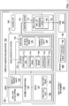
Figure 1 is an illustration of a block diagram of a manufacturing environment in which an illustrative example may be implemented; -
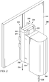
Figure 2 is an illustration of a perspective view of a vibration assisted drilling system in accordance with an illustrative example; -
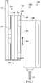
Figure 3 is an illustration of a side view of a vibration assisted drilling system in accordance with an illustrative example; -
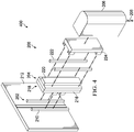
Figure 4 is an illustration of an exploded view of a vibration assisted drilling system in accordance with an illustrative example; -
Figure 5 is an illustration of a cross-sectional view of a drill bit of a vibration assisted drilling system in a hole in accordance with an illustrative example; -
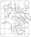
Figure 6 is an illustration of a perspective view of drilling debris in accordance with an illustrative example; -
Figure 7 is an illustration of a flowchart of a method of performing vibration assisted drilling in accordance with an illustrative example; -
Figure 8 is an illustration of an aircraft manufacturing and service method in a form of a block diagram in accordance with an illustrative example; and -
Figure 9 is an illustration of an aircraft in a form of a block diagram in which an illustrative example may be implemented. - The illustrative examples recognize and take into account one or more different considerations. The illustrative examples recognize and take into account that drilling metals, may result in long chips. Large drilling debris, such as long spiral strips or large chips can result in scratching at the hole wall. The illustrative examples recognize and take into account that large debris may also result in at least one of creating additional friction and additional heat, damaging hole surface and increasing the roughness, changing hole diameter which will affect performance, or producing unreliable chip extraction.
- The illustrative examples recognize and take into account that full retract pecking significantly increasing process times, limiting automation and rate capability. The illustrative examples recognize and take into account that conventional drilling processes can result in different sizes of debris. The debris can include long coiled debris. Conventional drilling can result in debris ranging in weight from about 20 mg to about 70 mg.
- The illustrative examples recognize and take into account that vibration assisted drilling (VAD) is being investigated to control drilling debris size. The illustrative examples recognize and take into account that vibration assisted drilling (VAD), the drilling temperature is lower than conventional drilling.
- The illustrative examples recognize and take into account that in some vibration assisted drilling devices, drill feed and oscillation motion are provided by one servo motor. In these illustrative examples, drill feed and oscillation motion are in the same axis. The oscillation frequency is limited by the servo motor response time. The illustrative examples recognize and take into account that in some vibration assisted drilling devices, oscillation is present within the drill spindle. The illustrative examples recognize and take into account that oscillation systems within a drill spindle are limited in size and type.
- Turning now to
Figure 1 , an illustration of a block diagram of a manufacturing environment in which an illustrative example may be implemented is depicted.Manufacturing environment 100 includes vibration assisteddrilling system 102 configured to perform vibration assisted drilling (VAD) onmaterial 104. Vibration assisteddrilling system 102 comprises drillfeed motion system 106 having adrill feed axis 108,oscillation motion system 110 having anoscillation axis 112, adrill spindle 114 having adrill bit 116, and amounting system 118 configured to connect thedrill spindle 114 to theoscillation motion system 110.Drill feed axis 108 is substantially parallel to and offset fromoscillation axis 112. - In vibration assisted
drilling system 102, feed oscillation is independent of main drill feed. Drillfeed motion system 106 comprises number oflinear rails 120 connected tobase 122. Drillfeed motion system 106 movesoscillation motion system 110 anddrill spindle 114 along number oflinear rails 120 to provide drill feed ofdrill bit 116. Servo 124 of drillfeed motion system 106 provides movement ofdrill spindle 114 in a drill feed direction.Servo 124 controlsdrill feed speed 126 and moves number of bearingcarts 128 alongdrill feed axis 108 on number oflinear rails 120. Linear bearing carts, number of bearingcarts 128, on rails, number oflinear rails 120, are able to handle bending movement induced by drilling end effector includingdrill spindle 114. -
Drill feed speed 126 is the speed at whichdrill bit 116 is directed towardsmaterial 104.Drill feed speed 126 is set based on desired operation.Drill feed speed 126 is limited by the capacity ofservo 124.Servo 124 is a motor including control circuitry and a shaft. -
Oscillation motion system 110 is connected to number of bearingcarts 128 of drillfeed motion system 106.Oscillation motion system 110 comprisesslip plane 130 andactuator 132 withoscillation axis 112.Slip plane 130 is a mechanical system configured to allow movement in a single axis. In some illustrative examples,slip plane 130 comprises number oflinear rails 134 and number of bearingcarts 136. Linear bearing carts, number of bearingcarts 136, on rails, number oflinear rails 134, are able to handle bending movement induced by drilling end effector includingdrill spindle 114. -
Actuator 132 moves number of bearingcarts 136 along number oflinear rails 134.Actuator 132 takes any desirable form. In some illustrative examples,actuator 132 is one of electro-magnetic 138, mechanical 140, or hydraulic 142.Actuator 132 providesoscillation speed 144 to number of bearingcarts 136 and components connected to number of bearingcarts 136.Actuator 132 is capable ofoscillation speed 144 greater than a maximum value ofdrill feed speed 126 for drillfeed motion system 106. - Specifications for
oscillation motion system 110 are determined based on the technical specifications ofdrilling hole 154 inmaterial 104. For example, desired specifications foroscillation motion system 110 can be affected by a type ofmaterial 104, a thickness ofmaterial 104, a size ofhole 154, an order of layers inmaterial 104, or other characteristics of the drilling process. In some illustrative examples,hole 154 has a diameter in the range of 0.25 inches to 0.875 inches. In some illustrative examples, oscillation amplitude ofactuator 132 is in the range of 0.06mm-0.20mm. In some illustrative examples, oscillation amplitude ofactuator 132 is in the range of 0.06mm-0.16mm. In some illustrative examples, oscillation frequency is desirably up to 100Hz. In some illustrative examples, oscillation frequency is in the range of 25Hz-80Hz. - In vibration assisted
drilling system 102, mountingsystem 118 mountsdrill spindle 114 to number of bearingcarts 136.Servo 124 drives number of bearingcarts 128 towardsmaterial 104 to providedrill feed speed 126 to drillspindle 114. As drillfeed motion system 106 provides movement ofdrill spindle 114 towardsmaterial 104,drill bit 116 is rotated. - As
drill spindle 114 is driven towardsmaterial 104 by movement of number of bearingcarts 128,drill spindle 114 is driven towards and away frommaterial 104 in an oscillating or "pecking" motion by movement of number of bearingcarts 136. Number of bearingcarts 136 are driven in an oscillating fashion byactuator 132. - Providing drill feed motion of
drill spindle 114 by drillfeed motion system 106 and oscillation motion ofdrill spindle 114 byoscillation motion system 110 provides greater oscillation speeds.Controller 146 is configured to control at least one ofservo 124,actuator 132, or a rotation actuator ofdrill bit 116.Controller 146 is configured to synchronizeoscillation speed 144 ofoscillation motion system 110 androtation speed 148 ofdrill bit 116 ofdrill spindle 114. In some illustrative examples,rotation speed 148 is referred to as RPM (rotations per minute) provided bydrill spindle 114. In some illustrative examples,drill spindle 114 RPM is up to 8000RPM. - By synchronizing
oscillation speed 144 androtation speed 148,chip size 150 ofdrilling debris 152 generated by vibration assisteddrilling system 102 is controlled. Vibration assisteddrilling system 102drills hole 154 and generatesdrilling debris 152 havingchip size 150.Chip size 150 is configured to provide reliable extraction ofdrilling debris 152. In some illustrative examples,chip size 150 is less than drilling debris generated by conventional drilling operations. In some illustrative examples,chip size 150 is less than 5 mg in weight. In some illustrative examples, tolerance forchip size 150 is +/- 1mg. - Vibration assisted
drilling system 102 comprises drillfeed motion system 106 havingservo 124 and number oflinear rails 120;oscillation motion system 110 havingactuator 132 andoscillation axis 112; anddrill spindle 114 havingdrill bit 116,drill spindle 114 mounted tooscillation motion system 110. Drillfeed motion system 106 hasdrill feed axis 108, andoscillation axis 112 is separated fromdrill feed axis 108. In vibration assisteddrilling system 102oscillation motion system 110 further comprisesslip plane 130. - In some illustrative examples, drill thrust load supplied by vibration assisted
drilling system 102 is up to 500 pounds. The drill thrust load limit is affected by an automation platform connected to assisteddrilling system 102. - The illustration of
manufacturing environment 100 inFigure 1 is not meant to imply physical or architectural limitations to the manner in which an illustrative example may be implemented. Other components in addition to or in place of the ones illustrated may be used. Some components may be unnecessary. Also, the blocks are presented to illustrate some functional components. One or more of these blocks may be combined, divided, or combined and divided into different blocks when implemented in an illustrative example. For example,slip plane 130 can take the form of another type of mechanical movement system other than number oflinear rails 134 and number of bearingcarts 136. - As another illustrative example, sensors associated with
drill spindle 114,oscillation motion system 110, and drillfeed motion system 106 are not depicted, but can be present for process monitoring and process control. - Turning now to
Figure 2 , an illustration of a perspective view of a vibration assisted drilling system is depicted in accordance with an illustrative example. Vibration assisteddrilling system 200 is a physical implementation of vibration assisteddrilling system 102 ofFigure 1 . - Vibration assisted
drilling system 200 comprises drillfeed motion system 202,oscillation motion system 204, anddrill spindle 206 havingdrill bit 208, and a mounting system (not depicted) configured to connectdrill spindle 206 tooscillation motion system 204. - In vibration assisted
drilling system 200, feed oscillation is independent of main drill feed. Drillfeed motion system 202 comprises number oflinear rails 210 connected tobase 212. Drillfeed motion system 202 movesoscillation motion system 204 anddrill spindle 206 along number oflinear rails 210 to provide drill feed ofdrill bit 208. Servo (not depicted) of drillfeed motion system 202 provides movement ofdrill spindle 206 in drill feed direction 214. The servo controls drill feed speed and moves number of bearingcarts 216 along number oflinear rails 210. -
Oscillation motion system 204 is connected to number of bearingcarts 216 of drillfeed motion system 202.Oscillation motion system 204 comprisesslip plane 218 andactuator 220.Slip plane 218 is a mechanical system configured to allow movement in a single axis. In some illustrative examples,slip plane 218 comprises number oflinear rails 222 and number of bearingcarts 224. - Turning now to
Figure 3 , an illustration of a side view of a vibration assisted drilling system is depicted in accordance with an illustrative example. View 300 is a side view of vibration assisteddrilling system 200 ofFigure 2 . - In
view 300 of vibration assisteddrilling system 200,drill feed axis 302 andoscillation axis 304 are indicated. Drillfeed motion system 202 hasdrill feed axis 302.Drill feed axis 302 is the axis along which number of bearingcarts 216 move.Oscillation motion system 204 hasoscillation axis 304.Drill feed axis 302 is substantially parallel to and offset fromoscillation axis 304. - Turning now to
Figure 4 , an illustration of an exploded view of a vibration assisted drilling system is depicted in accordance with an illustrative example. View 400 is an exploded view of vibration assisteddrilling system 200 ofFigure 2 . Inview 400, a servo of drillfeed motion system 202 is not depicted. In some illustrative examples, a servo motor (not depicted) couples with a drive attached tolinear rails 210. - The illustration of vibration assisted
drilling system 200 ofFigures 2-4 is not meant to imply physical or architectural limitations to the manner in which an illustrative example may be implemented. Other components in addition to or in place of the ones illustrated may be used. For example, inview 400,actuator 220, number oflinear rails 222, and number of bearingcarts 224 are part of a linear motor. Inview 400,actuator 220 takes the form of a magnetic plate of a linear motor system. In this illustrative example,actuator 220 is electro-magnetic.Actuator 220 takes any desirable form. In other non-depicted examples,actuator 220 is one of mechanical or hydraulic. In some non-depicted illustrative examples,actuator 220 includes a servo and a ball screw drive assembly connected to number of bearingcarts 224 ofoscillation motion system 204. Additionally, vibration assisteddrilling system 200 is not to scale. - Turning now to
Figure 5 , an illustration of a cross-sectional view of a drill bit of a vibration assisted drilling system in a hole is depicted in accordance with an illustrative example. View 500 is a cross-sectional view ofdrill bit 502 withinhole 504 ofmaterial 506.Drill bit 502 can be a physical implementation ofdrill bit 116 ofFigure 1 . In some illustrative examples,drill bit 502 is the same asdrill bit 208 ofFigures 2-4 . - As
drill bit 502 rotates,blade 508 andblade 510 remove drilling debris, such asdrilling debris 600 ofFigure 6 , frommaterial 506. Each ofblade 508 andblade 510 will remove a respective chip.Portion 512 will be removed by one ofblade 508 orblade 510 followingcut path 514.Portion 516 will be removed by the other ofblade 508 orblade 510 followingcut path 518. - Turning now to
Figure 6 , an illustration of a perspective view of drilling debris is depicted in accordance with an illustrative example. In some illustrative examples,drilling debris 600 is a physical implementation ofdrilling debris 152 ofFigure 1 . In some illustrative examples,drilling debris 600 is generated by vibration assisteddrilling system 200 ofFigures 2-4 . In some illustrative examples,drilling debris 600 is generated bydrilling material 506 usingdrill bit 502 ofFigure 5 . - Each chip of
drilling debris 600 has a substantially same size and shape. The size and shape of chips ofdrilling debris 600 is controlled by synchronization of the oscillation speed and rotation speed of a drill bit. Each chip ofdrilling debris 600 has a weight of approximately 3 mg. - Producing
drilling debris 600 of substantially the same size and shape and below 5mg in weight improves hole quality by fast and reliable chip extraction. Producingdrilling debris 600 reduces or prevents chips in interface. - The different components shown in
Figures 2-6 may be combined with components inFigure 1 , used with components inFigure 1 , or a combination of the two. Additionally, some of the components inFigures 2-6 may be illustrative examples of how components shown in block form inFigure 1 can be implemented as physical structures. - Turning now to
Figure 7 , an illustration of a flowchart of a method of performing vibration assisted drilling is depicted in accordance with an illustrative example.Method 700 can be performed inmanufacturing environment 100 using vibration assisteddrilling system 102.Method 700 can be performed using vibration assisteddrilling system 200 ofFigures 2-6 .Method 700 can be performed to producedrilling debris 600 ofFigure 6 . -
Method 700 moves a drill spindle towards a material by a drill feed motion system having a drill feed axis (operation 702).Method 700 rotates a drill bit of the drill spindle as the drill spindle is propelled towards the material (operation 704).Method 700 oscillates the drill spindle towards and away from the material by an oscillation motion system, wherein the oscillation motion system has an oscillation axis substantially parallel to and offset from the drill feed axis, and wherein the oscillation motion system connects the drill spindle to the drill feed motion system (operation 706). Afterwards,method 700 terminates. - In some illustrative examples,
method 700 synchronizes an oscillation speed of the oscillation motion system and a rotation speed of the drill bit of the drill spindle using a controller of a vibration assisted drilling system comprising the drill spindle, the oscillation motion system, and the drill feed motion system (operation 712). - In some illustrative examples, synchronizing the oscillation speed and the rotation speed of the drill bit while oscillating the drill spindle towards and away from the material removes drilling debris having a substantially uniform chip size (operation 714). The terms "approximately", "about", and "substantially" as used herein represent an amount close to the stated amount that still performs a desired function or achieves a desired result. For example, the terms "approximately", "about", and "substantially" may refer to an amount that is within less than 10% of, within less than 5% of, within less than 1% of, within less than 0.1% of, and within less than 0.01% of the stated amount. In some illustrative examples, the substantially uniform chip size is within a tolerance of +/- 1mg
- In some illustrative examples, 700 connects the oscillation motion system to the drill feed motion system (operation 708) and mounts the drill spindle to the oscillation motion system (operation 710).
- As used herein, the phrase "at least one of," when used with a list of items, means different combinations of one or more of the listed items may be used and only one of each item in the list may be needed. For example, "at least one of item A, item B, or item C" may include, without limitation, item A, item A and item B, or item B. This example also may include item A, item B, and item C or item B and item C. Of course, any combinations of these items may be present. In other examples, "at least one of" may be, for example, without limitation, two of item A; one of item B; and ten of item C; four of item B and seven of item C; or other suitable combinations. The item may be a particular object, thing, or a category. In other words, at least one of means any combination items and number of items may be used from the list but not all of the items in the list are required.
- As used herein, "a number of," when used with reference to items means one or more items.
- The flowcharts and block diagrams in the different depicted examples illustrate the architecture, functionality, and operation of some possible implementations of apparatuses and methods in an illustrative example. In this regard, each block in the flowcharts or block diagrams may represent at least one of a module, a segment, a function, or a portion of an operation or step.
- In some alternative implementations of an illustrative example, the function or functions noted in the blocks may occur out of the order noted in the figures. For example, in some cases, two blocks shown in succession may be executed substantially concurrently, or the blocks may sometimes be performed in the reverse order, depending upon the functionality involved. Also, other blocks may be added in addition to the illustrated blocks in a flowchart or block diagram. Some blocks may be optional. For example,
operations - Illustrative examples of the present disclosure may be described in the context of aircraft manufacturing and
service method 800 as shown inFigure 8 andaircraft 900 as shown inFigure 9 . Turning first toFigure 8 , an illustration of an aircraft manufacturing and service method is depicted in accordance with an illustrative example. During pre-production, aircraft manufacturing andservice method 800 may include specification anddesign 802 ofaircraft 900 inFigure 9 andmaterial procurement 804. - During production, component and
subassembly manufacturing 806 andsystem integration 808 ofaircraft 900 takes place. Thereafter,aircraft 900 may go through certification anddelivery 810 in order to be placed inservice 812. While inservice 812 by a customer,aircraft 900 is scheduled for routine maintenance andservice 814, which may include modification, reconfiguration, refurbishment, or other maintenance and service. - Each of the processes of aircraft manufacturing and
service method 800 may be performed or carried out by a system integrator, a third party, and/or an operator. In these examples, the operator may be a customer. For the purposes of this description, a system integrator may include, without limitation, any number of aircraft manufacturers and major-system subcontractors; a third party may include, without limitation, any number of vendors, subcontractors, and suppliers; and an operator may be an airline, a leasing company, a military entity, a service organization, and so on. - With reference now to
Figure 9 , an illustration of an aircraft is depicted in which an illustrative example may be implemented. In this example,aircraft 900 is produced by aircraft manufacturing andservice method 800 ofFigure 8 and may includeairframe 902 with plurality ofsystems 904 and interior 906. Examples ofsystems 904 include one or more ofpropulsion system 908,electrical system 910,hydraulic system 912, andenvironmental system 914. Any number of other systems may be included. - Apparatuses and methods embodied herein may be employed during at least one of the stages of aircraft manufacturing and
service method 800. One or more illustrative examples may be manufactured or used during at least one of component andsubassembly manufacturing 806,system integration 808, inservice 812, or maintenance andservice 814 ofFigure 8 .Aircraft 900 can include structures assembled using vibration assisteddrilling system 102 ofFigure 1 . Vibration assisteddrilling system 102 ofFigure 1 can be used during component andsubassembly manufacturing 806. As an example,method 800 can be used during component andsubassembly manufacturing 806 to drill holes to assemble a structure. In some illustrative examples, the structure drilled using vibration assisteddrilling system 102 ofFigure 1 is a component ofaircraft 900. - The illustrative examples present a vibration assisted drilling system having a drill feed axis and an oscillation axis parallel to and offset from the oscillation axis. The vibration assisted drilling system of the illustrative examples provides an external oscillation feed drive for timing base chip fragmentation through micro pecking. In the illustrative examples, feed oscillation is independent of main drill feed in the vibration assisted drilling system.
- The drill feed and oscillation motion are independently powered by introducing a sliding/oscillation table or slip plane between the servo and the drill spindle. By separating the drill feed actuator and the oscillation actuator, oscillation frequency can be much higher powered. The oscillation can be controlled by a different type of actuator than the drill feed servo. By separating the drill feed actuator and the oscillation actuator, the oscillation is not constrained by servo motor response.
- The implementation of vibration assisted drilling (VAD) with synchronized oscillation speed and drill bit rotation speed can decrease process time, thus increasing production rates. Vibration assisted drilling (VAD) with synchronized oscillation speed and drill bit rotation speed can improve hole quality by fast and reliable chip extraction. The illustrative examples can also reduce thrust and torque load. The smaller chips created by the illustrative examples produce less friction during drilling. The consistent chip fragmentation provided by the vibration assisted drilling (VAD) with synchronized oscillation speed and drill bit rotation speed reduces process load (thrust & torque load). With reduced thrust load, less adjacent clamping force can be used in the assembly stack. Thus, the illustrative examples can reduce at least one of torque load or clamping force.
- Vibration assisted drilling (VAD) with synchronized oscillation speed and drill bit rotation speed improves surface roughness. Vibration assisted drilling (VAD) with synchronized oscillation speed and drill bit rotation speed improves fatigue life of drill bits. Synchronizing the oscillation speed and drill bit rotation speed using a controller provides monitoring of tool wear and process loads.
- The vibration assisted drilling system with separate oscillation motion system enables the use of off shelf drilling spindle for end effector integration. Using an off the shelf drilling spindle reduces the costs of the vibration assisted drilling system. In some illustrative examples at least one of the feed drive or the oscillation source is also of the shelf.
- When the oscillation motion system is separated from feed drive axis, the oscillation/ sin wave motion is running independently of main feed drive motions. Therefore, the oscillation max frequency is no longer constrained by how fast the main feed drive (such as using servo motor) can react/respond, allowing higher max frequency for vibration assist drilling process and reducing drill cycle time.
- By providing the oscillation motion system as an external system from the drill spindle, the oscillation actuator sizing and types have more options than internal actuators to the drill spindle. Linear bearing cart on rails is an effective way to handle bending movement induced by a drilling end effector. Further, the disclosure comprises embodiments according to the following clauses:
- Clause 1. A vibration assisted drilling system comprising:
- a drill feed motion system having a drill feed axis;
- an oscillation motion system having an oscillation axis, wherein the drill feed axis is substantially parallel to and offset from the oscillation axis;
- a drill spindle having a drill bit; and
- a mounting system configured to connect the drill spindle to the oscillation motion system.
- Clause 2. The vibration assisted drilling system of Clause 1 further comprising:
a controller configured to synchronize an oscillation speed of the oscillation motion system and a rotation speed of the drill bit of the drill spindle. - Clause 3. The vibration assisted drilling system of Clause 1 or Clause 2, wherein the oscillation motion system comprises a slip plane and an actuator with the oscillation axis.
- Clause 4. The vibration assisted drilling system of Clause 3, wherein the slip plane comprises a number of linear rails and a number of bearing carts.
- Clause 5. The vibration assisted drilling system of Clause 4, wherein the drill spindle is mounted to the number of bearing carts.
- Clause 6. The vibration assisted drilling system of any of Clauses 3 to 5, wherein the actuator is one of electro-magnetic, mechanical, or hydraulic.
- Clause 7. The vibration assisted drilling system of any of Clauses 3 to 6, wherein the actuator is capable of an oscillation speed greater than a maximum value of a drill feed speed for the drill feed motion system.
- Clause 8. The vibration assisted drilling system of any of Clauses 1 to 7 wherein the drill feed motion system comprises a number of bearing carts and a number of linear rails, wherein the oscillation motion system is connected to the number of bearing carts.
- Clause 9. A vibration assisted drilling system comprising:
- a drill feed motion system having a servo and a number of linear rails, wherein the drill feed motion system has a drill feed axis;
- an oscillation motion system having an actuator and an oscillation axis, wherein the oscillation axis is separated from the drill feed axis; and
- a drill spindle having a drill bit, the drill spindle mounted to the oscillation motion system.
- Clause 10. The vibration assisted drilling system of Clause 9 wherein the oscillation motion system further comprises a slip plane.
- Clause 11. The vibration assisted drilling system of Clause 10, wherein the slip plane comprises a number of linear rails and a number of bearing carts.
- Clause 12. The vibration assisted drilling system of any of Clauses 9 to 11, wherein the actuator is one of electro-magnetic, mechanical, or hydraulic.
- Clause 13. The vibration assisted drilling system of any of Clauses 9 to 12 further comprising:
a controller configured to synchronize an oscillation speed of the oscillation motion system and a rotation speed of the drill bit of the drill spindle. - Clause 14. The vibration assisted drilling system of any of Clauses 9 to 13, wherein the actuator is capable of an oscillation speed greater than a maximum value of a drill feed speed for the drill feed motion system.
- Clause 15. A method of performing vibration assisted drilling comprising:
- moving a drill spindle towards a material by a drill feed motion system having a drill feed axis;
- rotating a drill bit of the drill spindle as the drill spindle is propelled towards the material; and
- oscillating the drill spindle towards and away from the material by an oscillation motion system, wherein the oscillation motion system has an oscillation axis substantially parallel to and offset from the drill feed axis, and wherein the oscillation motion system connects the drill spindle to the drill feed motion system.
- Clause 16. The method of Clause 15 further comprising:
synchronizing an oscillation speed of the oscillation motion system and a rotation speed of the drill bit of the drill spindle using a controller of a vibration assisted drilling system comprising the drill spindle, the oscillation motion system, and the drill feed motion system. - Clause 17. The method of Clause 16 wherein synchronizing the oscillation speed and the rotation speed of the drill bit while oscillating the drill spindle towards and away from the material removes drilling debris having a substantially uniform chip size.
- Clause 18. The method of any of Clauses 15 to 17 further comprising:
- connecting the oscillation motion system to the drill feed motion system; and
- mounting the drill spindle to the oscillation motion system.
- Clause 19. The method of any of Clauses 15 to 18, wherein the oscillation motion system comprises an actuator capable of an oscillation speed greater than a maximum value of a drill feed speed for the drill feed motion system.
- Clause 20. The method of Clause 19, wherein the actuator is one of electro-magnetic, mechanical, or hydraulic.
- The description of the different illustrative examples has been presented for purposes of illustration and description, and is not intended to be exhaustive or limited to the examples in the form disclosed. Many modifications and variations will be apparent to those of ordinary skill in the art. Further, different illustrative examples may provide different features as compared to other illustrative examples. The example or examples selected are chosen and described in order to best explain the principles of the examples, the practical application, and to enable others of ordinary skill in the art to understand the disclosure for various examples with various modifications as are suited to the particular use contemplated.
Claims (15)
- A vibration assisted drilling system (102) comprising:a drill feed motion system (106) having a drill feed axis (108);an oscillation motion system (110) having an oscillation axis (112), wherein the drill feed axis (108) is substantially parallel to and offset from the oscillation axis (112);a drill spindle (114) having a drill bit (116); anda mounting system (118) configured to connect the drill spindle (114) to the oscillation motion system (110).
- The vibration assisted drilling system (102) of claim 1 further comprising:
a controller (146) configured to synchronize an oscillation speed (144) of the oscillation motion system (110) and a rotation speed (148) of the drill bit (116) of the drill spindle (114) . - The vibration assisted drilling system (102) of claim 1 or claim 2, wherein the oscillation motion system (110) comprises a slip plane (130) and an actuator (132) with the oscillation axis (112) .
- The vibration assisted drilling system (102) of claim 3, wherein the slip plane (130) comprises a number of linear rails (134) and a number of bearing carts (136).
- The vibration assisted drilling system (102) of claim 4, wherein the drill spindle (114) is mounted to the number of bearing carts (136).
- The vibration assisted drilling system (102) of any of claims 3 to 5, wherein the actuator (132) is one of electro-magnetic (138), mechanical (140), or hydraulic (142).
- The vibration assisted drilling system (102) of any of claims 3 to 6, wherein the actuator (132) is capable of an oscillation speed (144) greater than a maximum value of a drill feed speed (126) for the drill feed motion system (106).
- The vibration assisted drilling system (102) of any of claims 1 to 7 wherein the drill feed motion system (106) comprises a number of bearing carts (128) and a number of linear rails (120), wherein the oscillation motion system (110) is connected to the number of bearing carts (128).
- A method (700) of performing vibration assisted drilling comprising:moving a drill spindle (114) towards a material (104) by a drill feed motion system (106) having a drill feed axis (108);rotating a drill bit (116) of the drill spindle (114) as the drill spindle (114) is propelled towards the material (104); andoscillating the drill spindle (114) towards and away from the material (104) by an oscillation motion system (110), wherein the oscillation motion system (110) has an oscillation axis (112) substantially parallel to and offset from the drill feed axis (108), and wherein the oscillation motion system (110) connects the drill spindle (114) to the drill feed motion system (106) .
- The method (700) of claim 9 further comprising:
synchronizing an oscillation speed (144) of the oscillation motion system (110) and a rotation speed (148) of the drill bit (116) of the drill spindle (114) using a controller (146) of a vibration assisted drilling system (102) comprising the drill spindle (114), the oscillation motion system (110), and the drill feed motion system (106). - The method (700) of claim 10 wherein synchronizing the oscillation speed (144) and the rotation speed (148) of the drill bit (116) while oscillating the drill spindle (114) towards and away from the material (104) removes drilling debris (152) having a substantially uniform chip size (150).
- The method (700) of any of claims 9 to 11 further comprising:connecting the oscillation motion system (110) to the drill feed motion system (106); andmounting the drill spindle (114) to the oscillation motion system (110).
- The method (700) of any of claims 9 to 12, wherein the oscillation motion system (110) comprises an actuator (132) capable of an oscillation speed (144) greater than a maximum value of a drill feed speed (126) for the drill feed motion system (106).
- The method (700) of claim 13, wherein the actuator (132) is one of electro-magnetic (138), mechanical (140), or hydraulic (142) .
- The method of any of claims 9 to 12, wherein the oscillation motion system (110) comprises a slip plane (130) and an actuator (132) with the oscillation axis (112).
Applications Claiming Priority (1)
| Application Number | Priority Date | Filing Date | Title |
|---|---|---|---|
| US16/780,740 US11148208B2 (en) | 2020-02-03 | 2020-02-03 | Vibration assisted drilling system and method of use |
Publications (1)
| Publication Number | Publication Date |
|---|---|
| EP3862118A1 true EP3862118A1 (en) | 2021-08-11 |
Family
ID=74236044
Family Applications (1)
| Application Number | Title | Priority Date | Filing Date |
|---|---|---|---|
| EP21153217.1A Pending EP3862118A1 (en) | 2020-02-03 | 2021-01-25 | Vibration assisted drilling system and method of use |
Country Status (4)
| Country | Link |
|---|---|
| US (1) | US11148208B2 (en) |
| EP (1) | EP3862118A1 (en) |
| CN (1) | CN113199282B (en) |
| BR (1) | BR102021001354A2 (en) |
Families Citing this family (2)
| Publication number | Priority date | Publication date | Assignee | Title |
|---|---|---|---|---|
| SE546148C2 (en) * | 2022-04-21 | 2024-06-11 | Husqvarna Ab | Electric power cutter with a vibration function |
| CN114951752B (en) * | 2022-06-27 | 2023-06-16 | 中北大学 | Ultrasonic vibration auxiliary electric spark back taper micropore machining device |
Citations (7)
| Publication number | Priority date | Publication date | Assignee | Title |
|---|---|---|---|---|
| CN101412185A (en) * | 2008-11-25 | 2009-04-22 | 鲜于哲善 | Numerical control drilling-milling apparatus having a plurality of independent process systems |
| JP2009214286A (en) * | 2008-03-11 | 2009-09-24 | Fuji Kogyo Kk | Ultrasonic vibration machining unit device and working method for fiber-reinforced resin and the like using the same, large-sized boring machine and multi-articulated robot and working method for fiber-reinforced resin and the like using them |
| CN104181006A (en) * | 2014-08-06 | 2014-12-03 | 哈尔滨工业大学 | Ultrasonic-assisted rock cutting and coring testing platform |
| CN107378035A (en) * | 2017-07-31 | 2017-11-24 | 深圳利工科技有限公司 | A kind of vertical numerical control deep hole drilling machine |
| CN207388015U (en) * | 2017-09-25 | 2018-05-22 | 华侨大学 | Precision ultrasonic puncher |
| EP3354403A1 (en) * | 2015-09-24 | 2018-08-01 | Citizen Watch Co., Ltd. | Machine tool control device, and machine tool equipped with said control device |
| US20190054583A1 (en) * | 2015-04-08 | 2019-02-21 | Lti Motion Gmbh | Tool drive having a spindle shaft and operating method |
Family Cites Families (15)
| Publication number | Priority date | Publication date | Assignee | Title |
|---|---|---|---|---|
| US2073518A (en) * | 1932-10-08 | 1937-03-09 | Leland Gifford Co | Hydraulic machine tool |
| US2260327A (en) * | 1939-08-31 | 1941-10-28 | Avey Drilling Machine Company | Machine tool |
| US2515851A (en) * | 1948-04-19 | 1950-07-18 | Bendix Aviat Corp | High-speed drilling machine |
| US2922323A (en) * | 1953-06-18 | 1960-01-26 | Air Prod Inc | Automatic high speed deep hole drilling machine |
| US2853903A (en) * | 1956-08-31 | 1958-09-30 | Adolph F Hauser | Micro-drilling machine |
| US4123188A (en) * | 1977-04-04 | 1978-10-31 | Gardner-Denver Company | Control system for peck drilling tool |
| JPS6014659B2 (en) * | 1979-10-03 | 1985-04-15 | ブラザー工業株式会社 | Step feed device in machine tools |
| DE4419610C2 (en) * | 1994-06-03 | 1997-07-10 | Niles Simmons Industrieanlagen | CNC lathe for heavy machining |
| DE102007053350B4 (en) * | 2007-10-30 | 2013-10-10 | Chiron-Werke Gmbh & Co Kg | Method for machining workpieces |
| JP5033929B1 (en) * | 2011-11-10 | 2012-09-26 | ハリキ精工株式会社 | Machine Tools |
| CN202776463U (en) * | 2012-09-12 | 2013-03-13 | 江苏久信医用净化工程有限公司 | Vibration drilling based bone drilling device for orthopedic operation |
| DE102014005543B3 (en) * | 2014-04-16 | 2015-02-19 | Innolite Gmbh | Method and device for ultra-precise machining of a curved and ferrous negative surface of a mold insert, mold insert and an optical element produced therewith |
| EP3199271B1 (en) * | 2014-09-22 | 2020-08-12 | Citizen Watch Co., Ltd. | Machine tool and control device for machine tool |
| CN104959639B (en) * | 2015-07-21 | 2017-06-27 | 大连理工大学 | An ultrasonic vibration drilling end effector |
| CN108214941A (en) * | 2017-12-31 | 2018-06-29 | 桂林电子科技大学 | Ultra-thin tempered glass automatic drilling lathe based on binocular camera shooting identification |
-
2020
- 2020-02-03 US US16/780,740 patent/US11148208B2/en active Active
-
2021
- 2021-01-25 EP EP21153217.1A patent/EP3862118A1/en active Pending
- 2021-01-25 BR BR102021001354-0A patent/BR102021001354A2/en unknown
- 2021-02-03 CN CN202110147286.6A patent/CN113199282B/en active Active
Patent Citations (7)
| Publication number | Priority date | Publication date | Assignee | Title |
|---|---|---|---|---|
| JP2009214286A (en) * | 2008-03-11 | 2009-09-24 | Fuji Kogyo Kk | Ultrasonic vibration machining unit device and working method for fiber-reinforced resin and the like using the same, large-sized boring machine and multi-articulated robot and working method for fiber-reinforced resin and the like using them |
| CN101412185A (en) * | 2008-11-25 | 2009-04-22 | 鲜于哲善 | Numerical control drilling-milling apparatus having a plurality of independent process systems |
| CN104181006A (en) * | 2014-08-06 | 2014-12-03 | 哈尔滨工业大学 | Ultrasonic-assisted rock cutting and coring testing platform |
| US20190054583A1 (en) * | 2015-04-08 | 2019-02-21 | Lti Motion Gmbh | Tool drive having a spindle shaft and operating method |
| EP3354403A1 (en) * | 2015-09-24 | 2018-08-01 | Citizen Watch Co., Ltd. | Machine tool control device, and machine tool equipped with said control device |
| CN107378035A (en) * | 2017-07-31 | 2017-11-24 | 深圳利工科技有限公司 | A kind of vertical numerical control deep hole drilling machine |
| CN207388015U (en) * | 2017-09-25 | 2018-05-22 | 华侨大学 | Precision ultrasonic puncher |
Also Published As
| Publication number | Publication date |
|---|---|
| CN113199282B (en) | 2025-08-29 |
| CN113199282A (en) | 2021-08-03 |
| US11148208B2 (en) | 2021-10-19 |
| US20210237172A1 (en) | 2021-08-05 |
| BR102021001354A2 (en) | 2021-09-28 |
Similar Documents
| Publication | Publication Date | Title |
|---|---|---|
| CN107530853B (en) | Tool driver with spindle shaft and method of operation | |
| EP3862118A1 (en) | Vibration assisted drilling system and method of use | |
| JP5200005B2 (en) | Tool holder assembly for vibration-based machining and vibration-based machining method | |
| CN103128554B (en) | The method for boring hole of this lathe boring cylinder body of cutter head, lathe and use | |
| JP6441607B2 (en) | Fluid supply vacuum cutter | |
| CN101443147B (en) | Cutter head, machine tool and boring method for boring cylinder body using the machine tool | |
| US8662372B2 (en) | Apparatus for friction stir welding using spindle-in-spindle | |
| US11660684B2 (en) | Method and apparatus for machining a workpiece | |
| CN112705751B (en) | Self-adaptive vibration hole making method for robot | |
| CN104417761A (en) | System and method for forming perforations in a barrel section | |
| CN101633060A (en) | Automatic spiral hole-milling unit | |
| US7627940B2 (en) | Orbital hole match drilling | |
| US12285830B2 (en) | Spindle with piezoelectric actuators | |
| CN105728811A (en) | A method and system for robotized spiral hole-making in laminated structure of aircraft fuselage | |
| CN105612017A (en) | Tool spindle having an active magnetic bearing | |
| CN120347245A (en) | Multi-shaft linkage machining system for drilling and milling inner wall of deep hole | |
| CN116330054A (en) | Flexible self-adaptive flux linkage cutter finishing device, method and motion platform | |
| JP2023531634A (en) | MACHINE TOOL AND METHOD FOR CUTTING WORK | |
| CN201493498U (en) | Spiral drilling device | |
| CN208195740U (en) | A kind of boring cutter of camshaft | |
| CN121339939A (en) | A large-diameter stepped hole sleeve drilling system |
Legal Events
| Date | Code | Title | Description |
|---|---|---|---|
| PUAI | Public reference made under article 153(3) epc to a published international application that has entered the european phase |
Free format text: ORIGINAL CODE: 0009012 |
|
| STAA | Information on the status of an ep patent application or granted ep patent |
Free format text: STATUS: THE APPLICATION HAS BEEN PUBLISHED |
|
| AK | Designated contracting states |
Kind code of ref document: A1 Designated state(s): AL AT BE BG CH CY CZ DE DK EE ES FI FR GB GR HR HU IE IS IT LI LT LU LV MC MK MT NL NO PL PT RO RS SE SI SK SM TR |
|
| STAA | Information on the status of an ep patent application or granted ep patent |
Free format text: STATUS: REQUEST FOR EXAMINATION WAS MADE |
|
| 17P | Request for examination filed |
Effective date: 20211223 |
|
| RBV | Designated contracting states (corrected) |
Designated state(s): AL AT BE BG CH CY CZ DE DK EE ES FI FR GB GR HR HU IE IS IT LI LT LU LV MC MK MT NL NO PL PT RO RS SE SI SK SM TR |
|
| RAP3 | Party data changed (applicant data changed or rights of an application transferred) |
Owner name: THE BOEING COMPANY |
|
| STAA | Information on the status of an ep patent application or granted ep patent |
Free format text: STATUS: EXAMINATION IS IN PROGRESS |
|
| 17Q | First examination report despatched |
Effective date: 20251203 |