EP3861959A1 - Uniform scaling of haptic actuators - Google Patents
Uniform scaling of haptic actuators Download PDFInfo
- Publication number
- EP3861959A1 EP3861959A1 EP21153588.5A EP21153588A EP3861959A1 EP 3861959 A1 EP3861959 A1 EP 3861959A1 EP 21153588 A EP21153588 A EP 21153588A EP 3861959 A1 EP3861959 A1 EP 3861959A1
- Authority
- EP
- European Patent Office
- Prior art keywords
- actuator
- force
- haptic feedback
- output
- commanded
- Prior art date
- Legal status (The legal status is an assumption and is not a legal conclusion. Google has not performed a legal analysis and makes no representation as to the accuracy of the status listed.)
- Granted
Links
Images


Classifications
-
- A—HUMAN NECESSITIES
- A61—MEDICAL OR VETERINARY SCIENCE; HYGIENE
- A61B—DIAGNOSIS; SURGERY; IDENTIFICATION
- A61B34/00—Computer-aided surgery; Manipulators or robots specially adapted for use in surgery
- A61B34/70—Manipulators specially adapted for use in surgery
- A61B34/76—Manipulators having means for providing feel, e.g. force or tactile feedback
-
- A—HUMAN NECESSITIES
- A61—MEDICAL OR VETERINARY SCIENCE; HYGIENE
- A61B—DIAGNOSIS; SURGERY; IDENTIFICATION
- A61B34/00—Computer-aided surgery; Manipulators or robots specially adapted for use in surgery
- A61B34/30—Surgical robots
-
- A—HUMAN NECESSITIES
- A61—MEDICAL OR VETERINARY SCIENCE; HYGIENE
- A61B—DIAGNOSIS; SURGERY; IDENTIFICATION
- A61B34/00—Computer-aided surgery; Manipulators or robots specially adapted for use in surgery
- A61B34/30—Surgical robots
- A61B34/35—Surgical robots for telesurgery
-
- A—HUMAN NECESSITIES
- A61—MEDICAL OR VETERINARY SCIENCE; HYGIENE
- A61B—DIAGNOSIS; SURGERY; IDENTIFICATION
- A61B34/00—Computer-aided surgery; Manipulators or robots specially adapted for use in surgery
- A61B34/70—Manipulators specially adapted for use in surgery
- A61B34/77—Manipulators with motion or force scaling
-
- A—HUMAN NECESSITIES
- A61—MEDICAL OR VETERINARY SCIENCE; HYGIENE
- A61B—DIAGNOSIS; SURGERY; IDENTIFICATION
- A61B90/00—Instruments, implements or accessories specially adapted for surgery or diagnosis and not covered by any of the groups A61B1/00 - A61B50/00, e.g. for luxation treatment or for protecting wound edges
- A61B90/03—Automatic limiting or abutting means, e.g. for safety
-
- A—HUMAN NECESSITIES
- A61—MEDICAL OR VETERINARY SCIENCE; HYGIENE
- A61B—DIAGNOSIS; SURGERY; IDENTIFICATION
- A61B90/00—Instruments, implements or accessories specially adapted for surgery or diagnosis and not covered by any of the groups A61B1/00 - A61B50/00, e.g. for luxation treatment or for protecting wound edges
- A61B90/06—Measuring instruments not otherwise provided for
-
- A—HUMAN NECESSITIES
- A61—MEDICAL OR VETERINARY SCIENCE; HYGIENE
- A61B—DIAGNOSIS; SURGERY; IDENTIFICATION
- A61B90/00—Instruments, implements or accessories specially adapted for surgery or diagnosis and not covered by any of the groups A61B1/00 - A61B50/00, e.g. for luxation treatment or for protecting wound edges
- A61B90/06—Measuring instruments not otherwise provided for
- A61B2090/064—Measuring instruments not otherwise provided for for measuring force, pressure or mechanical tension
Definitions
- the present invention is directed towards systems and methods for providing haptic feedback to the operator of a surgical system, and more particularly to maintaining an intuitive haptic profile for the user when haptic feedback actuators reach performance limits.
- Tele-operated surgical systems are often intended to enhance surgeon precision and/or reduce patient trauma during a medical procedure.
- a surgeon interacts with input devices (sometimes referred to as "masters” or “master controllers”) to control surgical instruments that are actuated by drive mechanisms such as motors.
- masters or “master controllers”
- drive mechanisms such as motors.
- the surgeon is not directly manipulating the surgical instruments, in can sometimes be beneficial to provide haptic feedback at the input devices that indicates or replicates interaction forces (e.g., felt at the surgical instruments, other elements of the surgical system, and/or virtual or synthetic elements/features generated by the surgical system).
- interaction forces e.g., felt at the surgical instruments, other elements of the surgical system, and/or virtual or synthetic elements/features generated by the surgical system.
- the force feedback being presented to the user may be the sum of the feedback from a sensor, from an algorithm, from a user interface cue, collision detection, model interaction, etc.
- the surgeon would ideally experience a seamless haptic experience through system state and configuration changes.
- this can be difficult to accomplish, for example the actuators used to provide the haptic feedback are have different performance limits or if different actuators reach their performance limits at different times.
- the haptic feedback presented to the user may not properly align with the perceived user experience (e.g., actual force being sensed at the surgical instrument or the visual representation of the interactive object), resulting in a confusing or non-intuitive user experience.
- motor torque limits i.e. saturation limits
- performance limits can be created for several reasons including to protect the motor from overheating, to limit the force applied to the surgeon/patient, and/or to keep the motor in it's ideal torque operating range.
- Limiting the torque at the motor can yield non-isotropic force saturation at the interface (e.g., the handle of the input device or the tip of the instrument). This means when you are trying to present a force at the interface that involves two or more motors, the force direction can be incorrect if one motor is restricted by a motor torque limit.
- the user may be feeling a force in a given direction, but as the force applied to the user increases and reaches a torque limit for any of the motors associated with render the force to the user, the direction of the force displayed to the user begins to rotate which can be disconcerting and/or confusing for the user.
- the outputs of the haptic feedback actuators are scaled whenever one or more of the actuators reaches a predetermined output threshold, thereby maintaining proper haptic feedback directionality when individual actuators would otherwise be commanded to operate outside their accurate performance range. Such scaling may change the overall haptic feedback magnitude, but allows the haptic feedback direction to be appropriately maintained.
- a monitoring process can determine when an output of an actuator would exceed a maximum threshold output (at or below the software-defined output limit), and at that point scale down the output of at least one of the other actuators so that the desired direction of the total output (e.g., force or torque) is maintained.
- the monitoring process can additionally or alternatively determine when an output of an actuator would fall below a minimum output threshold (below which the actuator output may be too low to generate accurately), and at that point scale up its output and that of at least one of the other actuators so that the desired direction of the total output (e.g., force or torque) is maintained.
- all actuators are scaled when one reaches its threshold output, while in other embodiments, only concurrently active actuators are scaled.
- the output thresholds for the actuators are fixed, and in various other embodiments, the output thresholds for the actuators can vary over time or based on actuator and/or system status.
- the outputs of the haptic feedback actuators are scaled whenever a commanded output of one or more of the actuators falls outside a predetermined working range for that actuator.
- the predetermined working range can be defined by a maximum output threshold equal to or less than the output limit of the actuator, and/or a minimum output threshold equal to or greater than a minimum accurate output level of the actuator. Such scaling may reduce the overall haptic feedback magnitude, but allows the haptic feedback direction to be appropriately maintained, which is often a more critical aspect of haptic feedback.
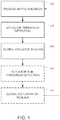
- FIG. 1 shows an exemplary method for providing directionally consistent haptic feedback when actuator output limits are exceeded.
- a surgical system that allows a user (e.g., surgeon) to control a surgical instrument (and/or other elements of the surgical system, such as a robotic arm, set up structure, or positioning element such as a boom or cart) via an input device(s) (e.g., lever(s), gripper(s), joystick(s), or any other structure capable of receiving user input), and then provides force feedback to that input device based on a desired haptic feedback profile (a set of one or more haptic feedback effects that at least partially reproduce or represent the physical experience of a real or virtual/modeled interaction).
- a desired haptic feedback profile a set of one or more haptic feedback effects that at least partially reproduce or represent the physical experience of a real or virtual/modeled interaction.
- the haptic feedback profile can be based on any haptic model input, such as sensed forces at the instrument (e.g., tissue or other instrument interactions) or robotic arm (e.g., arm collisions with structures or staff), user guidance (e.g., haptic detents, fences, or other profiles to provide guidance for the user to move the input device(s) along a desired path or trajectory), and user interface (UI) elements (e.g., presenting a virtual handle or steering wheel to the user).
- UI user interface
- This haptic feedback can be anything from direct replication of the haptic feedback profile, to scaling of the haptic feedback profile, to applying a nonlinear modification of the haptic feedback profile, or any other transformation (e.g., force scaling that varies depending on one or more other factors such as instrument state/speed, viewing magnification, etc.).
- the actual force feedback provided at the input device is generated by two or more actuators (e.g., motors, drives, or any other motive elements) that work cooperatively to provide feedback of varying force and direction.
- actuators e.g., motors, drives, or any other motive elements
- an input device having pitch and yaw capabilities may be coupled to a first pair of actuators that apply forces in opposing directions about the pitch axis, and a second pair of actuators that apply forces in opposing directions about the yaw axis.
- Two or more of the pitch and yaw actuators can then be used simultaneously to provide force feedback that is offset from the pitch and yaw axes.
- actuators generally do not have performance characteristics that are exactly the same, whether due to inherent performance limitations or due to operational constraints/effects (e.g., heat, mechanical restrictions). For example, one out of the group of haptic feedback actuators will typically reach its maximum output level before the others. Any commanded output beyond that maximum output level will not result in any increased output, and consequently any haptic feedback that involves the maxed-out actuator will likely deviate from the expected force feedback direction. Additionally, the actuators will may begin producing noisier (less precise) outputs as outputs decrease below a certain level, such that haptic feedback below a certain level may also deviate from the expected force feedback direction.
- FIG. 2A graphically depicts an example of this haptic offset, with the outputs of first and second actuators ("Actuator 1" and “Actuator 2", respectively) represented by the graph's horizontal and vertical axes, respectively. Also indicated on the axes of the graph are output limits OL1 and OL2 for the first and second actuators, respectively, representing the output limits for the first and second actuators.
- the actuators cannot exceed their output limits, which may be static (e.g., defined by inherent performance characteristics of the actuators), or dynamic (e.g., based on a current parameter of an actuator, such as temperature, or a physical restriction such as a kinematic configuration of the driven structure that places the actuator in a mechanically unfavorable position).
- static e.g., defined by inherent performance characteristics of the actuators
- dynamic e.g., based on a current parameter of an actuator, such as temperature, or a physical restriction such as a kinematic configuration of the driven structure that places the actuator in a mechanically unfavorable position.
- a commanded output of an actuator exceeds its output limit, such as indicated by desired (commanded) feedback force FD.
- actuator 1 receives a commanded output CO1 and actuator 2 receives a commanded output CO2.
- Commanded output CO1 is less than output limit OL1, and so can be provided by actuator 1.
- commanded output CO2 is greater than output limit OL2
- the actual output of actuator 2 will be limited to output level OL2, resulting in an overall feedback force FO that is both smaller than, and offset from, desired feedback force FD. While a slight variability in the magnitude of haptic feedback can generally be accommodated by a user without much difficulty, a deviation in force direction can be quite misleading to a user and can result in improper control actions by the user in response.
- any commanded output for an actuator that exceeds a maximum output threshold for that actuator is identified.
- the maximum output threshold for an actuator can be defined as the output limit for that actuator, in various other embodiments the maximum output threshold could be set at a level below the output limit to provide a buffer for detecting the approach of the actuator limit and/or applying the scaling factor (as described in greater detail below) before any output limits are reached.
- the maximum output thresholds for the haptic feedback actuators can be either static or dynamic, and can be individualized or common across the actuators.
- a common scaling factor is applied to the commanded outputs for the actuators.
- the scaling factor is selected to keep the output of the identified actuator (i.e., the actuator identified in step 120 having a commanded output greater than its output threshold) less than its output limit. Because the scaling factor is applied to the commanded output for each actuator, the direction of the overall force is maintained, with a reduced overall magnitude. Note that in some embodiments, if multiple actuators would receive commanded outputs that would exceed their output limits, the scaling factor would be based on the commanded output that exceeds its associated actuator's output threshold by the greatest amount - i.e., the scaling factor would be based on the "worst" output discrepancy.
- FIG. 2B graphically depicts an example of this haptic scaling, relative to the same first and second actuator characteristics (output limits OL1 and OL2, respectively) and desired feedback force FD.
- a scaling factor is applied to the commanded outputs CO1 and CO2 to reduce both proportionately to adjusted commanded outputs CO1' and CO2', respectively.
- the scaling factor is selected such that adjusted commanded output CO2' reduced at least to output limit OL2, although in various other embodiments the scaling factor can be selected to cause adjusted commanded output CO2' to be some increment less than output limit OL2.
- actuators 1 and 2 could additionally or alternatively exhibit reduced output accuracy at low output levels.
- a scaling factor could be applied to commanded outputs CO1 and CO2 if either is less than a minimum output threshold for actuator 1 or actuator 2, respectively. The scaling factor would then increase the adjusted commanded outputs CO1' and CO2' above the level at which output accuracy is degraded.
- the minimum output thresholds for the haptic feedback actuators can be either static or dynamic, and can be individualized or common across the actuators.
- the application of the scaling factor results in an overall scaled feedback force FS that is aligned directionally with the original desired feedback force FD.
- a consistent haptic experience can be provided even with the change in force magnitude so long as directional consistency of the force feedback is maintained.
- step 120 when it is detected that the commanded output (unscaled) for the actuator identified in step 120 would go beyond the output threshold (e.g., exceed the maximum output threshold or fall below the minimum output threshold) for that actuator in an optional ACTUATOR SUB-THRESHOLD DETECTION step 140, the scaling factor applied to all commanded outputs in step 130 is removed (or set to 1) in an optional GLOBAL ACTUATOR DE-SCALING step 150.
- unsealed haptic feedback is provided going forward.
- the output thresholds for the haptic feedback actuators can be dynamic - i.e., the specific values can change depending on actuator operational parameters, input device kinematic configuration, or various other factors.
- the output threshold(s) applied in step 120 can have different values.
- different actuators can trigger step 120 over the course of operation of the surgical system.
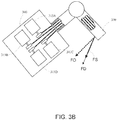
- FIGS. 3A and 3B shows block diagram of a surgical system 300 incorporating haptic feedback at an input device 330 and means for providing a consistent haptic experience for the user as described above with respect to FIGS. 1 , 2A, and 2B .
- Surgical system 300 includes an instrument 310 for performing a surgical task (e.g., forceps, cutter, retractor, vessel sealer, needle driver, catheter, etc.), an input device 330 (e.g., a lever(s), gripper(s), joystick(s), or any other structure capable of receiving user input) for receiving inputs from a user (e.g., surgeon), and a controller 320 for receiving input instructions from input device 330, controlling the actions of instrument 310 accordingly via a manipulation structure 313, and providing instructions to a haptic feedback actuation mechanism 340 to provide haptic feedback to input device 330 according to a desired haptic feedback profile.
- a surgical task e.g., forceps, cutter, retractor, vessel sealer,
- manipulation structure 313 can include any number of systems and structures for maneuvering, positioning, actuating, or otherwise controlling the behavior of instrument 310, including a robotic arm(s)/manipulator(s), set up structure(s), and/or positioning element(s) such as a boom(s) or cart(s), among others.
- Controller 320 can include any combination of hardware, software, firmware, and other modalities for generating, managing, controlling, and effecting the actions described herein.
- controller 320 can be integrated with instrument 310, input device 330, and/or discrete control hardware (e.g., a standalone processing unit or computing platform).
- FIG. 3A shows an end effector 311 at the end of a shaft 312 of instrument 310 grasping a portion of tissue 390 (e.g., retraction).
- a force FM at end effector 311 which would ideally be delivered as a desired haptic feedback profile force FD at input device 330.
- the actual haptic feedback delivery is enabled by haptic feedback actuation mechanism 340, which includes multiple actuators that attempt to provide the haptic feedback profile force FD to present the surgeon with a "feel" of the resistance being provided by tissue 390 as it is being retracted.
- haptic feedback profile force FD is described as being derived from a force FM sensed at end effector 311 of instrument 310 for exemplary purposes, in various other embodiments, force FM could be sensed at any location for which corresponding haptic feedback at input device 330 would be beneficial, such as interactions at shaft 312 or any other element of manipulation structure 313 (e.g., arm collisions with structures or staff).
- force FM can be defined according to non-physical parameters, such as guidance or user interface features.
- surgical system 300 can include a display 350 (e.g., a monitor(s), a head-in viewer(s), projections, video glasses/belmet(s), and/or any other graphical presentation element).
- display 350 can present a virtual or synthetic element 361 that can be interacted with via input device 330.
- synthetic element 361 can be used as a supplemental interface for interacting with a physical component of surgical system 300. For example, as shown in FIG.
- synthetic element 361 can be a virtual handle or knob that can be "grasped” and dragged around using input device 330 to reposition instrument 310 at the surgical site.
- synthetic element 361 can provide a purely virtual interaction element, such as a dial, toggle, lever, or any other structure for controlling surgical system 300.
- controller 320 can then attempt to provide an appropriate haptic feedback profile force FD at input device 330.
- surgical system 300 may provide guidance to the user with respect to movement of instrument 310 and/or input device 330.
- a desired motion of instrument 310 e.g., a targeted or safe dissection path, a desired retraction movement, or any other beneficial articulation
- controller 320 can then attempt to provide an appropriate haptic feedback profile force FD at input device 330.
- FIG. 3B shows an exemplary block diagram of actuation mechanism 340 that includes multiple actuators 341 that apply components of the haptic feedback force to input device 330.
- actuation mechanism 340 can include any number and type of actuators (e.g., rotary actuators, linear actuators, hydraulics, and/or piezo-electric, vibrotactile, or fluidic actuators) and/or force transmission mechanisms (e.g., direct drive, linkages, gearing, etc.).
- actuators e.g., rotary actuators, linear actuators, hydraulics, and/or piezo-electric, vibrotactile, or fluidic actuators
- force transmission mechanisms e.g., direct drive, linkages, gearing, etc.
- controller 320 detects that a commanded output for any of actuators 341 would go beyond that actuator's defined output threshold (as described above with respect to step 120 in FIG. 1 ), it applies a common scaling factor to the commanded outputs supplied to each actuator 341 such that the commanded outputs for all actuators 341 remain within their predetermined working range (as described above with respect to step 130 in FIG. 1 ).
- This has the effect of changing the output of all actuators 341 proportionately, which in turn results in a scaled haptic feedback force FS that, while different in magnitude with respect to the desired feedback force FD, remains directionally aligned with desired feedback force FD (as described above with respect to FIG. 2B ).
- controller 320 when controller 320 detects that the unscaled commanded outputs would no longer go beyond the defined output thresholds for any of actuators 341, the scaling factor can be eliminated (or set to 1), thereby allowing restoration of unscaled haptic feedback at input device 330 (as described above with respect to steps 140 and 150 in FIG. 1 ).
Landscapes
- Health & Medical Sciences (AREA)
- Surgery (AREA)
- Life Sciences & Earth Sciences (AREA)
- Engineering & Computer Science (AREA)
- Medical Informatics (AREA)
- General Health & Medical Sciences (AREA)
- Biomedical Technology (AREA)
- Heart & Thoracic Surgery (AREA)
- Nuclear Medicine, Radiotherapy & Molecular Imaging (AREA)
- Molecular Biology (AREA)
- Animal Behavior & Ethology (AREA)
- Veterinary Medicine (AREA)
- Public Health (AREA)
- Robotics (AREA)
- Oral & Maxillofacial Surgery (AREA)
- Pathology (AREA)
- Manipulator (AREA)
- User Interface Of Digital Computer (AREA)
Abstract
Description
- This application claims the benefit of priority to
U.S. Provisional Patent Application No. 62/277,827, filed on January 12, 2016 - The present invention is directed towards systems and methods for providing haptic feedback to the operator of a surgical system, and more particularly to maintaining an intuitive haptic profile for the user when haptic feedback actuators reach performance limits.
- Tele-operated surgical systems are often intended to enhance surgeon precision and/or reduce patient trauma during a medical procedure. In such systems, a surgeon interacts with input devices (sometimes referred to as "masters" or "master controllers") to control surgical instruments that are actuated by drive mechanisms such as motors. Because the surgeon is not directly manipulating the surgical instruments, in can sometimes be beneficial to provide haptic feedback at the input devices that indicates or replicates interaction forces (e.g., felt at the surgical instruments, other elements of the surgical system, and/or virtual or synthetic elements/features generated by the surgical system). Note that the force feedback being presented to the user may be the sum of the feedback from a sensor, from an algorithm, from a user interface cue, collision detection, model interaction, etc.
- To provide a good user experience, the surgeon would ideally experience a seamless haptic experience through system state and configuration changes. However, this can be difficult to accomplish, for example the actuators used to provide the haptic feedback are have different performance limits or if different actuators reach their performance limits at different times. In such instances, the haptic feedback presented to the user may not properly align with the perceived user experience (e.g., actual force being sensed at the surgical instrument or the visual representation of the interactive object), resulting in a confusing or non-intuitive user experience.
- For example, motor torque limits (i.e. saturation limits) are typically imposed in software for robotic interfaces. These performance limits can be created for several reasons including to protect the motor from overheating, to limit the force applied to the surgeon/patient, and/or to keep the motor in it's ideal torque operating range. Limiting the torque at the motor can yield non-isotropic force saturation at the interface (e.g., the handle of the input device or the tip of the instrument). This means when you are trying to present a force at the interface that involves two or more motors, the force direction can be incorrect if one motor is restricted by a motor torque limit.
- This can be especially problematic when rendering force to the user (haptic feedback) at the input device. The user may be feeling a force in a given direction, but as the force applied to the user increases and reaches a torque limit for any of the motors associated with render the force to the user, the direction of the force displayed to the user begins to rotate which can be disconcerting and/or confusing for the user.
- It is therefore desirable to provide a system and method for ensuring haptic feedback that is consistent with the force environment at the surgical instrument.
- To minimize discrepancies between expected force directions and haptic force feedback directions, the outputs of the haptic feedback actuators are scaled whenever one or more of the actuators reaches a predetermined output threshold, thereby maintaining proper haptic feedback directionality when individual actuators would otherwise be commanded to operate outside their accurate performance range. Such scaling may change the overall haptic feedback magnitude, but allows the haptic feedback direction to be appropriately maintained.
- In some embodiments, where software limits the output of any actuator, a monitoring process can determine when an output of an actuator would exceed a maximum threshold output (at or below the software-defined output limit), and at that point scale down the output of at least one of the other actuators so that the desired direction of the total output (e.g., force or torque) is maintained. In some embodiments, the monitoring process can additionally or alternatively determine when an output of an actuator would fall below a minimum output threshold (below which the actuator output may be too low to generate accurately), and at that point scale up its output and that of at least one of the other actuators so that the desired direction of the total output (e.g., force or torque) is maintained. In some embodiments, all actuators are scaled when one reaches its threshold output, while in other embodiments, only concurrently active actuators are scaled. In some embodiments, the output thresholds for the actuators are fixed, and in various other embodiments, the output thresholds for the actuators can vary over time or based on actuator and/or system status.
- It is to be understood that both the foregoing general description and the following detailed description are exemplary and explanatory in nature and are intended to provide an understanding of the present disclosure without limiting the scope of the present disclosure. In that regard, additional aspects, features, and advantages of the present disclosure will be apparent to one skilled in the art from the following detailed description.
- Aspects of the present disclosure are best understood from the following detailed description when read with the accompanying figures. It is emphasized that, in accordance with the standard practice in the industry, various features are not drawn to scale. In fact, the dimensions of the various features may be arbitrarily increased or reduced for clarity of discussion. In addition, the present disclosure may repeat reference numerals and/or letters in the various examples. This repetition is for the purpose of simplicity and clarity and does not in itself dictate a relationship between the various embodiments and/or configurations discussed.
-
FIG. 1 shows a method of providing consistent haptic feedback to a user of a surgical system as actuator maximum outputs are reached, in accordance with various embodiments of the invention. -
FIGS. 2A and 2B shows an exemplary haptic force vector outputs when actuator output maximums are ignored vs. addressed. -
FIG. 3A-3B show an exemplary surgical system providing haptic force feedback responsive to actuator output maximum thresholds, in accordance with various embodiments of the invention. - In the following detailed description of the aspects of the invention, numerous specific details are set forth in order to provide a thorough understanding of the disclosed embodiments. However, it will be obvious to one skilled in the art that the embodiments of this disclosure may be practiced without these specific details. In other instances well known methods, procedures, components, and circuits have not been described in detail so as not to unnecessarily obscure aspects of the embodiments of the invention. And, to avoid needless descriptive repetition, one or more components or actions described in accordance with one illustrative embodiment can be used or omitted as applicable from other illustrative embodiments.
- To minimize discrepancies between desired (e.g., sensed or modeled by a surgical system) and actual haptic force feedback directions, the outputs of the haptic feedback actuators are scaled whenever a commanded output of one or more of the actuators falls outside a predetermined working range for that actuator. The predetermined working range can be defined by a maximum output threshold equal to or less than the output limit of the actuator, and/or a minimum output threshold equal to or greater than a minimum accurate output level of the actuator. Such scaling may reduce the overall haptic feedback magnitude, but allows the haptic feedback direction to be appropriately maintained, which is often a more critical aspect of haptic feedback.
-
FIG. 1 shows an exemplary method for providing directionally consistent haptic feedback when actuator output limits are exceeded. In a PROVIDE HAPTIC FEEDBACKstep 110, a surgical system that allows a user (e.g., surgeon) to control a surgical instrument (and/or other elements of the surgical system, such as a robotic arm, set up structure, or positioning element such as a boom or cart) via an input device(s) (e.g., lever(s), gripper(s), joystick(s), or any other structure capable of receiving user input), and then provides force feedback to that input device based on a desired haptic feedback profile (a set of one or more haptic feedback effects that at least partially reproduce or represent the physical experience of a real or virtual/modeled interaction). The haptic feedback profile can be based on any haptic model input, such as sensed forces at the instrument (e.g., tissue or other instrument interactions) or robotic arm (e.g., arm collisions with structures or staff), user guidance (e.g., haptic detents, fences, or other profiles to provide guidance for the user to move the input device(s) along a desired path or trajectory), and user interface (UI) elements (e.g., presenting a virtual handle or steering wheel to the user). This haptic feedback can be anything from direct replication of the haptic feedback profile, to scaling of the haptic feedback profile, to applying a nonlinear modification of the haptic feedback profile, or any other transformation (e.g., force scaling that varies depending on one or more other factors such as instrument state/speed, viewing magnification, etc.). - The actual force feedback provided at the input device is generated by two or more actuators (e.g., motors, drives, or any other motive elements) that work cooperatively to provide feedback of varying force and direction. For example, an input device having pitch and yaw capabilities may be coupled to a first pair of actuators that apply forces in opposing directions about the pitch axis, and a second pair of actuators that apply forces in opposing directions about the yaw axis. Two or more of the pitch and yaw actuators can then be used simultaneously to provide force feedback that is offset from the pitch and yaw axes.
- Because actuators generally do not have performance characteristics that are exactly the same, whether due to inherent performance limitations or due to operational constraints/effects (e.g., heat, mechanical restrictions). For example, one out of the group of haptic feedback actuators will typically reach its maximum output level before the others. Any commanded output beyond that maximum output level will not result in any increased output, and consequently any haptic feedback that involves the maxed-out actuator will likely deviate from the expected force feedback direction. Additionally, the actuators will may begin producing noisier (less precise) outputs as outputs decrease below a certain level, such that haptic feedback below a certain level may also deviate from the expected force feedback direction.
-
FIG. 2A graphically depicts an example of this haptic offset, with the outputs of first and second actuators ("Actuator 1" and "Actuator 2", respectively) represented by the graph's horizontal and vertical axes, respectively. Also indicated on the axes of the graph are output limits OL1 and OL2 for the first and second actuators, respectively, representing the output limits for the first and second actuators. - As noted above, the actuators cannot exceed their output limits, which may be static (e.g., defined by inherent performance characteristics of the actuators), or dynamic (e.g., based on a current parameter of an actuator, such as temperature, or a physical restriction such as a kinematic configuration of the driven structure that places the actuator in a mechanically unfavorable position).
- The problem thus arises if a commanded output of an actuator exceeds its output limit, such as indicated by desired (commanded) feedback force FD. To generate desired feedback force FD,
actuator 1 receives a commanded output CO1 andactuator 2 receives a commanded output CO2. Commanded output CO1 is less than output limit OL1, and so can be provided byactuator 1. However, because commanded output CO2 is greater than output limit OL2, the actual output ofactuator 2 will be limited to output level OL2, resulting in an overall feedback force FO that is both smaller than, and offset from, desired feedback force FD. While a slight variability in the magnitude of haptic feedback can generally be accommodated by a user without much difficulty, a deviation in force direction can be quite misleading to a user and can result in improper control actions by the user in response. - Returning to
FIG. 1 , to mitigate this force feedback offset issue, in an ACTUATORTHRESHOLD DETECTION step 120, any commanded output for an actuator that exceeds a maximum output threshold for that actuator is identified. Note that while in some embodiments the maximum output threshold for an actuator can be defined as the output limit for that actuator, in various other embodiments the maximum output threshold could be set at a level below the output limit to provide a buffer for detecting the approach of the actuator limit and/or applying the scaling factor (as described in greater detail below) before any output limits are reached. Note further that as described above, the maximum output thresholds for the haptic feedback actuators can be either static or dynamic, and can be individualized or common across the actuators. - Then, in a GLOBAL
ACTUATOR SCALING step 130, a common scaling factor is applied to the commanded outputs for the actuators. The scaling factor is selected to keep the output of the identified actuator (i.e., the actuator identified instep 120 having a commanded output greater than its output threshold) less than its output limit. Because the scaling factor is applied to the commanded output for each actuator, the direction of the overall force is maintained, with a reduced overall magnitude. Note that in some embodiments, if multiple actuators would receive commanded outputs that would exceed their output limits, the scaling factor would be based on the commanded output that exceeds its associated actuator's output threshold by the greatest amount - i.e., the scaling factor would be based on the "worst" output discrepancy. -
FIG. 2B graphically depicts an example of this haptic scaling, relative to the same first and second actuator characteristics (output limits OL1 and OL2, respectively) and desired feedback force FD. However, rather than allowing the output limits associated withactuator 2 to pull the overall haptic force off the desired force direction as shown inFIG. 2A , a scaling factor is applied to the commanded outputs CO1 and CO2 to reduce both proportionately to adjusted commanded outputs CO1' and CO2', respectively. The scaling factor is selected such that adjusted commanded output CO2' reduced at least to output limit OL2, although in various other embodiments the scaling factor can be selected to cause adjusted commanded output CO2' to be some increment less than output limit OL2. - In some embodiments,
actuators actuator 1 oractuator 2, respectively. The scaling factor would then increase the adjusted commanded outputs CO1' and CO2' above the level at which output accuracy is degraded. Note that as described above, the minimum output thresholds for the haptic feedback actuators can be either static or dynamic, and can be individualized or common across the actuators. - In any event, the application of the scaling factor results in an overall scaled feedback force FS that is aligned directionally with the original desired feedback force FD. As noted above, a consistent haptic experience can be provided even with the change in force magnitude so long as directional consistency of the force feedback is maintained.
- Returning to
FIG. 1 , in various embodiments, when it is detected that the commanded output (unscaled) for the actuator identified instep 120 would go beyond the output threshold (e.g., exceed the maximum output threshold or fall below the minimum output threshold) for that actuator in an optional ACTUATORSUB-THRESHOLD DETECTION step 140, the scaling factor applied to all commanded outputs instep 130 is removed (or set to 1) in an optional GLOBAL ACTUATORDE-SCALING step 150. Returning to step 110, unsealed haptic feedback is provided going forward. - As noted previously, in some embodiments, the output thresholds for the haptic feedback actuators can be dynamic - i.e., the specific values can change depending on actuator operational parameters, input device kinematic configuration, or various other factors. In such embodiments, over the course of operation of the surgical system, the output threshold(s) applied in
step 120 can have different values. In addition, in various other embodiments, different actuators can triggerstep 120 over the course of operation of the surgical system. -
FIGS. 3A and3B shows block diagram of asurgical system 300 incorporating haptic feedback at aninput device 330 and means for providing a consistent haptic experience for the user as described above with respect toFIGS. 1 ,2A, and 2B .Surgical system 300 includes aninstrument 310 for performing a surgical task (e.g., forceps, cutter, retractor, vessel sealer, needle driver, catheter, etc.), an input device 330 (e.g., a lever(s), gripper(s), joystick(s), or any other structure capable of receiving user input) for receiving inputs from a user (e.g., surgeon), and acontroller 320 for receiving input instructions frominput device 330, controlling the actions ofinstrument 310 accordingly via amanipulation structure 313, and providing instructions to a hapticfeedback actuation mechanism 340 to provide haptic feedback toinput device 330 according to a desired haptic feedback profile. In various embodiments,manipulation structure 313 can include any number of systems and structures for maneuvering, positioning, actuating, or otherwise controlling the behavior ofinstrument 310, including a robotic arm(s)/manipulator(s), set up structure(s), and/or positioning element(s) such as a boom(s) or cart(s), among others.Controller 320 can include any combination of hardware, software, firmware, and other modalities for generating, managing, controlling, and effecting the actions described herein. In various embodiments,controller 320 can be integrated withinstrument 310,input device 330, and/or discrete control hardware (e.g., a standalone processing unit or computing platform). - For exemplary purposes,
FIG. 3A shows anend effector 311 at the end of ashaft 312 ofinstrument 310 grasping a portion of tissue 390 (e.g., retraction). This results in a force FM atend effector 311, which would ideally be delivered as a desired haptic feedback profile force FD atinput device 330. The actual haptic feedback delivery is enabled by hapticfeedback actuation mechanism 340, which includes multiple actuators that attempt to provide the haptic feedback profile force FD to present the surgeon with a "feel" of the resistance being provided bytissue 390 as it is being retracted. - Although the haptic feedback profile force FD is described as being derived from a force FM sensed at
end effector 311 ofinstrument 310 for exemplary purposes, in various other embodiments, force FM could be sensed at any location for which corresponding haptic feedback atinput device 330 would be beneficial, such as interactions atshaft 312 or any other element of manipulation structure 313 (e.g., arm collisions with structures or staff). - In various other embodiments, force FM can be defined according to non-physical parameters, such as guidance or user interface features. For example, in some embodiments,
surgical system 300 can include a display 350 (e.g., a monitor(s), a head-in viewer(s), projections, video glasses/belmet(s), and/or any other graphical presentation element). In various embodiments,display 350 can present a virtual orsynthetic element 361 that can be interacted with viainput device 330. In some embodiments,synthetic element 361 can be used as a supplemental interface for interacting with a physical component ofsurgical system 300. For example, as shown inFIG. 3A ,synthetic element 361 can be a virtual handle or knob that can be "grasped" and dragged around usinginput device 330 to repositioninstrument 310 at the surgical site. In other embodiments,synthetic element 361 can provide a purely virtual interaction element, such as a dial, toggle, lever, or any other structure for controllingsurgical system 300. In any case, by generating a haptic feedback profile based on model forces FM1 associated with interacting with synthetic element 361 (e.g., radially outward resistive force produced with grasping a round knob),controller 320 can then attempt to provide an appropriate haptic feedback profile force FD atinput device 330. - In various other embodiments,
surgical system 300 may provide guidance to the user with respect to movement ofinstrument 310 and/orinput device 330. For example, a desired motion of instrument 310 (e.g., a targeted or safe dissection path, a desired retraction movement, or any other beneficial articulation) could optionally be defined as atrajectory 362. By generating a haptic feedback profile based on model forces FM2 associated with maintaining the position ofinstrument 310 along trajectory 362 (e.g., inwardly directed forces produced upon deviations from trajectory 362),controller 320 can then attempt to provide an appropriate haptic feedback profile force FD atinput device 330. -
FIG. 3B shows an exemplary block diagram ofactuation mechanism 340 that includes multiple actuators 341 that apply components of the haptic feedback force to inputdevice 330. Note that while four actuators that driveinput device 330 via cables or tendons are depicted for descriptive purposes, in various other embodiments,actuation mechanism 340 can include any number and type of actuators (e.g., rotary actuators, linear actuators, hydraulics, and/or piezo-electric, vibrotactile, or fluidic actuators) and/or force transmission mechanisms (e.g., direct drive, linkages, gearing, etc.). - The various actuators 341 provide actuation outputs (e.g., torque or force) in combination with one another in an effort to produce the desired haptic feedback profile force FD. However, if desired haptic feedback profile force FD requires an output from one of actuators 341 that falls outside its working range, attempting to use the commanded outputs for actuators 341 without modification would result in an unmodified haptic feedback force FO having both a magnitude and direction different than desired force FD (as described above with respect to
FIGS. 1 and2A ). As described above, the working range of an actuator can be defined by a maximum output threshold (e.g., at or below the output limit of the actuator) and/or a minimum output threshold (e.g., at or above a minimum reliable output level of the actuator). - Therefore, when
controller 320 detects that a commanded output for any of actuators 341 would go beyond that actuator's defined output threshold (as described above with respect to step 120 inFIG. 1 ), it applies a common scaling factor to the commanded outputs supplied to each actuator 341 such that the commanded outputs for all actuators 341 remain within their predetermined working range (as described above with respect to step 130 inFIG. 1 ). This has the effect of changing the output of all actuators 341 proportionately, which in turn results in a scaled haptic feedback force FS that, while different in magnitude with respect to the desired feedback force FD, remains directionally aligned with desired feedback force FD (as described above with respect toFIG. 2B ). - In various embodiments, when
controller 320 detects that the unscaled commanded outputs would no longer go beyond the defined output thresholds for any of actuators 341, the scaling factor can be eliminated (or set to 1), thereby allowing restoration of unscaled haptic feedback at input device 330 (as described above with respect tosteps FIG. 1 ). - While certain exemplary embodiments of the invention have been described and shown in the accompanying drawings, it is to be understood that such embodiments are merely illustrative of and not restrictive on the broad invention, and that the embodiments of the invention not be limited to the specific constructions and arrangements shown and described, since various other modifications may occur to those ordinarily skilled in the art.
- The present application also includes the following numbered clauses:
- 1. A surgical system comprising:
- an input device;
- a first actuator and a second actuator coupled to the input device to provide haptic feedback at the input device;
- a controller for controlling the first actuator and the second actuator,
- the controller configured to apply a first scale factor to a first commanded output and a second commanded output for the first actuator the second actuator, respectively, when the first commanded output would fall outside a first predetermined working range of the first actuator, wherein the first scale factor adjusts the first commanded output to be within the first predetermined working range.
- 2. The surgical system of
Clause 1, further comprising a third actuator coupled to the input device, wherein the controller is further configured to apply the first scale factor to a third commanded output for the third actuator to provide the haptic feedback. - 3. The surgical system of
Clause 1, wherein the controller is further configured to remove the first scale factor from the first commanded output and the second commanded output when the first commanded output would fall within the first predetermined working range. - 4. The surgical system of
Clause 1, wherein the first predetermined working range comprises a maximum output threshold that is less than or equal to an output limit of the first actuator. - 5. The surgical system of any of
Clauses 1 to 4, wherein the first predetermined working range comprises a minimum output threshold that is greater than or equal to a minimum reliable output level of the first actuator. - 6. The surgical system of any of
Clauses 1 to 4, wherein the first predetermined working range is at least partially based on a kinematic configuration of the input device. - 7. The surgical system of
Clause 1, wherein the controller is further configured to change the first scale factor to a second scale factor when the the first commanded output scaled by the first scale factor would fall outside the first predetermined working range, and
wherein the second scale factor adjusts the first commanded output to fall within the first commanded range. - 8. The surgical system of
Clause 1, wherein the controller is further configured to apply a second scale factor to the first commanded output and the second commanded output when the second commanded output scaled by the first scale factor would fall outside a second predetermined working range for the second actuator, and
wherein applying the first scale factor and the second scale factor to the second commanded output adjusts the second commanded output to fall within the second predetermined working range. - 9. A method for operating a surgical system comprising an input device, and a first actuator and a second actuator coupled to the input device, the method comprising:
- detecting that a first commanded output for the first actuator would fall outside a first predetermined working range for the first actuator; and
- providing haptic feedback at the input device by applying a first scale factor to the first commanded output and a second commanded output for the second actuator, wherein the first scale factor causes the first commanded output to fall within the first predetermined working range.
- 10. The method of Clause 9, wherein a third actuator is coupled to the input device, and
wherein providing the haptic feedback further comprises applying the first scale factor to a third commanded output for the third actuator. - 11. The method of Clause 9, further comprising removing the first scale factor from the first commanded output and the second commanded output upon detecting that the first commanded output would fall within the first predetermined working range.
- 12. The method of Clause 9, wherein the first predetermined working range comprises at least one of a maximum output threshold that is less than or equal to an output limit of the first actuator, and a minimum output threshold that is greater than or equal to a minimum reliable output level of the first actuator.
- 13. The method of Clause 9, further comprising:
- detecting that the first commanded output scaled by the first scale factor would fall outside the first predetermined working range; and
- changing the first scale factor to a second scale factor, wherein the second scale factor adjusts the first commanded output to fall within the first predetermined working range.
- 14. The method of Clause 9, further comprising:
- detecting that the second commanded output scaled by the first scale factor would fall outside a second predetermined working range for the second actuator; and
- applying a second scale factor to the first commanded output and the second commanded output, wherein the first scale factor and the second scale factor adjust the second commanded output to fall within the second predetermined working range.
- 15. The method of Clause 14, wherein the first predetermined working range is different from the second predetermined working range.
Claims (10)
- A surgical system comprising:an input device;a first actuator coupled to the input device;a second actuator coupled to the input device; anda controller;wherein the input device is capable of receiving input from a user and providing a haptic feedback force to the user;wherein the first actuator has a maximum output threshold force and a minimum reliable output level force;wherein a working range of the first actuator is defined by an upper limit at or below the maximum output threshold force of the first actuator and a lower limit at or above the minimum reliable output level force of the first actuator;wherein the controller determines first commanded output haptic feedback force for the first actuator to provide to the input device and second commanded output haptic feedback force for the second actuator to provide to the input device;wherein on a condition in which the first commanded output haptic feedback force would fall outside the working range of the first actuator, the controller applies a common first scaling factor to the first commanded output haptic feedback force for the first actuator to provide to the input device and to the second commanded output haptic feedback force for the second actuator to provide to the input device; andwherein the first scaling factor adjusts the first commanded output haptic feedback force to be within the working range of the first actuator.
- The surgical system of claim 1, wherein:the second actuator has a maximum output threshold force and a minimum reliable output level force;a working range of the second actuator is defined by an upper limit at or below the maximum output threshold force of the second actuator and a output limit at or above the minimum reliable output level force of the second actuator; andthe first scaling factor adjusts the second commanded output haptic feedback force to be within the working range of the second actuator.
- The surgical system of claim 1 or 2, wherein:the condition in which the first commanded output haptic feedback force would fall outside the working range of the first actuator occurs at a first time;at a second time after the first time and on a second condition in which the first commanded output haptic feedback force would fall within the working range of the first actuator, the controller removes the first scaling factor from the first commanded output haptic feedback force and the second commanded output haptic feedback force.
- The surgical system of any of claims 1-3, wherein:the condition in which the first commanded output haptic feedback force would fall outside the working range of the first actuator occurs at a first time;at a second time after the first time and on a second condition in which the first scaling factor applied to the first commanded output haptic feedback force would cause the first actuator to output a force outside the first working range of the first actuator, the controller applies a second scaling factor to the first commanded output haptic feedback force and to the second commanded output haptic feedback force; andthe second scaling factor adjusts the first commanded output haptic feedback force to be within the first working range of the first actuator.
- The surgical system of any of claims 1-3, wherein:the condition in which the first commanded output haptic feedback force would fall outside the working range of the first actuator occurs at a first time;at a second time after the first time and on a second condition in which the first scaling factor applied to the first commanded output haptic feedback force would cause the second actuator to output a force outside the second working range of the second actuator, the controller applies a second scaling factor to the first commanded output haptic feedback force and to the second commanded output haptic feedback force; andthe second scaling factor adjusts the second commanded output haptic feedback force to be within the second working range of the second actuator.
- The surgical system of any of claims 1-5, wherein:
the condition in which the first commanded output haptic feedback force would fall outside the first working range of the first actuator is a condition in which the first commanded output haptic feedback force would be larger than the upper output limit of the first working range of the first actuator. - The surgical system of any of claims 1-5, wherein:
the condition in which the first commanded output haptic feedback force would fall outside the first working range of the first actuator is a condition in which the first commanded output haptic feedback force would be smaller than the lower output limit of the first working range of the first actuator. - The surgical system of any of claims 1-7, wherein:
the maximum output threshold force of the first actuator, the minimum reliable output level force of the first actuator, or both the maximum output threshold force and the minimum reliable output level force of the first actuator are dynamic and based on a kinematic configuration of the input device. - The surgical system of any of claims 1-7, wherein:
the maximum output threshold force of the first actuator, the minimum reliable output level force of the first actuator, or both the maximum output threshold force and the minimum reliable output level force of the first actuator are dynamic and based on a current parameter of the first actuator. - The surgical system of any of claims 1-9, wherein:the first commanded output haptic feedback force urges the input device in a first direction; andthe second commanded output haptic feedback force urges the input device in a second direction different from the first direction.
Priority Applications (1)
| Application Number | Priority Date | Filing Date | Title |
|---|---|---|---|
| EP24185514.7A EP4414816A3 (en) | 2016-01-12 | 2017-01-12 | Uniform scaling of haptic actuators |
Applications Claiming Priority (3)
| Application Number | Priority Date | Filing Date | Title |
|---|---|---|---|
| US201662277827P | 2016-01-12 | 2016-01-12 | |
| PCT/US2017/013239 WO2017123797A1 (en) | 2016-01-12 | 2017-01-12 | Uniform scaling of haptic actuators |
| EP17738964.0A EP3402434B1 (en) | 2016-01-12 | 2017-01-12 | Uniform scaling of haptic actuators |
Related Parent Applications (2)
| Application Number | Title | Priority Date | Filing Date |
|---|---|---|---|
| EP17738964.0A Division EP3402434B1 (en) | 2016-01-12 | 2017-01-12 | Uniform scaling of haptic actuators |
| EP17738964.0A Division-Into EP3402434B1 (en) | 2016-01-12 | 2017-01-12 | Uniform scaling of haptic actuators |
Related Child Applications (2)
| Application Number | Title | Priority Date | Filing Date |
|---|---|---|---|
| EP24185514.7A Division-Into EP4414816A3 (en) | 2016-01-12 | 2017-01-12 | Uniform scaling of haptic actuators |
| EP24185514.7A Division EP4414816A3 (en) | 2016-01-12 | 2017-01-12 | Uniform scaling of haptic actuators |
Publications (2)
| Publication Number | Publication Date |
|---|---|
| EP3861959A1 true EP3861959A1 (en) | 2021-08-11 |
| EP3861959B1 EP3861959B1 (en) | 2024-12-11 |
Family
ID=59311475
Family Applications (3)
| Application Number | Title | Priority Date | Filing Date |
|---|---|---|---|
| EP17738964.0A Active EP3402434B1 (en) | 2016-01-12 | 2017-01-12 | Uniform scaling of haptic actuators |
| EP21153588.5A Active EP3861959B1 (en) | 2016-01-12 | 2017-01-12 | Uniform scaling of haptic actuators |
| EP24185514.7A Pending EP4414816A3 (en) | 2016-01-12 | 2017-01-12 | Uniform scaling of haptic actuators |
Family Applications Before (1)
| Application Number | Title | Priority Date | Filing Date |
|---|---|---|---|
| EP17738964.0A Active EP3402434B1 (en) | 2016-01-12 | 2017-01-12 | Uniform scaling of haptic actuators |
Family Applications After (1)
| Application Number | Title | Priority Date | Filing Date |
|---|---|---|---|
| EP24185514.7A Pending EP4414816A3 (en) | 2016-01-12 | 2017-01-12 | Uniform scaling of haptic actuators |
Country Status (6)
| Country | Link |
|---|---|
| US (3) | US11376087B2 (en) |
| EP (3) | EP3402434B1 (en) |
| JP (2) | JP7182464B2 (en) |
| KR (1) | KR102651324B1 (en) |
| CN (2) | CN114886569B (en) |
| WO (1) | WO2017123797A1 (en) |
Families Citing this family (13)
| Publication number | Priority date | Publication date | Assignee | Title |
|---|---|---|---|---|
| WO2017123797A1 (en) * | 2016-01-12 | 2017-07-20 | Intuitive Surgical Operations, Inc. | Uniform scaling of haptic actuators |
| EP3834765B1 (en) | 2016-01-12 | 2024-07-17 | Intuitive Surgical Operations, Inc. | Staged force feedback transitioning between control states |
| KR102443324B1 (en) * | 2017-09-15 | 2022-09-14 | 풔스 디멘션 에스에이알엘 | Vibro-tactile force feedback method and device |
| US11666402B2 (en) | 2017-10-02 | 2023-06-06 | Intuitive Surgical Operations, Inc. | End effector force feedback to master controller |
| FR3092984A1 (en) * | 2019-02-25 | 2020-08-28 | Fondation B-Com | Method and device for assisting the handling of a medical instrument by a user |
| JP6807122B1 (en) * | 2020-02-12 | 2021-01-06 | リバーフィールド株式会社 | Surgical robot and control unit for surgical robot |
| WO2021203197A1 (en) * | 2020-04-07 | 2021-10-14 | The Royal Institution For The Advancement Of Learning / Mcgill University | Methods and systems for controlling a haptic display |
| US20240359335A1 (en) * | 2021-03-30 | 2024-10-31 | Keio University | Control system, control device, and control method |
| DE102021204495A1 (en) * | 2021-05-04 | 2022-11-10 | Kuka Deutschland Gmbh | Method and system for controlling a telerobot |
| US20230046473A1 (en) * | 2021-08-16 | 2023-02-16 | Covidien Lp | End effector drive mechanisms for surgical instruments such as for use in robotic surgical systems |
| US20230047289A1 (en) * | 2021-08-16 | 2023-02-16 | Covidien Lp | End effector drive mechanisms for surgical instruments such as for use in robotic surgical systems |
| EP4522054A1 (en) * | 2022-05-11 | 2025-03-19 | Intuitive Surgical Operations, Inc. | Techniques for controlling a computer-assisted system |
| EP4531746A1 (en) * | 2022-05-31 | 2025-04-09 | Intuitive Surgical Operations, Inc. | Adaptive damper for computer-assisted system |
Citations (5)
| Publication number | Priority date | Publication date | Assignee | Title |
|---|---|---|---|---|
| US4604016A (en) * | 1983-08-03 | 1986-08-05 | Joyce Stephen A | Multi-dimensional force-torque hand controller having force feedback |
| WO2006120666A1 (en) * | 2005-05-10 | 2006-11-16 | Navicath Ltd. | User interface for remote control catheterization |
| US20070142968A1 (en) * | 2005-12-20 | 2007-06-21 | Intuitive Surgical Inc. | Robotic surgical system with joint motion controller adapted to reduce instrument tip vibrations |
| US20130289767A1 (en) * | 2012-04-30 | 2013-10-31 | Samsung Electronics Co., Ltd. | Apparatus and method for controlling force to be used for motion of surgical robot |
| US20150360365A1 (en) * | 2014-06-16 | 2015-12-17 | Panasonic Intellectual Property Management Co., Ltd. | Control apparatus and control method for master-slave robot, master-slave robot, control program for master-slave robot, and integrated electronic circuit for controlling master-slave robot |
Family Cites Families (95)
| Publication number | Priority date | Publication date | Assignee | Title |
|---|---|---|---|---|
| US4160508A (en) | 1977-08-19 | 1979-07-10 | Nasa | Controller arm for a remotely related slave arm |
| US5116180A (en) * | 1988-07-18 | 1992-05-26 | Spar Aerospace Limited | Human-in-the-loop machine control loop |
| US5631973A (en) | 1994-05-05 | 1997-05-20 | Sri International | Method for telemanipulation with telepresence |
| US6963792B1 (en) | 1992-01-21 | 2005-11-08 | Sri International | Surgical method |
| US5762458A (en) | 1996-02-20 | 1998-06-09 | Computer Motion, Inc. | Method and apparatus for performing minimally invasive cardiac procedures |
| US5382885A (en) * | 1993-08-09 | 1995-01-17 | The University Of British Columbia | Motion scaling tele-operating system with force feedback suitable for microsurgery |
| US5710870A (en) | 1995-09-07 | 1998-01-20 | California Institute Of Technology | Decoupled six degree-of-freedom robot manipulator |
| US6639581B1 (en) * | 1995-11-17 | 2003-10-28 | Immersion Corporation | Flexure mechanism for interface device |
| US5855583A (en) | 1996-02-20 | 1999-01-05 | Computer Motion, Inc. | Method and apparatus for performing minimally invasive cardiac procedures |
| US5767648A (en) | 1996-04-19 | 1998-06-16 | Massachusetts Institute Of Technology | Base force/torque sensor apparatus for the precise control of manipulators with joint friction and a method of use thereof |
| US6024576A (en) | 1996-09-06 | 2000-02-15 | Immersion Corporation | Hemispherical, high bandwidth mechanical interface for computer systems |
| US6411276B1 (en) * | 1996-11-13 | 2002-06-25 | Immersion Corporation | Hybrid control of haptic feedback for host computer and interface device |
| US6810281B2 (en) * | 2000-12-21 | 2004-10-26 | Endovia Medical, Inc. | Medical mapping system |
| US6692485B1 (en) | 1998-02-24 | 2004-02-17 | Endovia Medical, Inc. | Articulated apparatus for telemanipulator system |
| US6459926B1 (en) | 1998-11-20 | 2002-10-01 | Intuitive Surgical, Inc. | Repositioning and reorientation of master/slave relationship in minimally invasive telesurgery |
| WO2000030557A1 (en) * | 1998-11-23 | 2000-06-02 | Microdexterity Systems, Inc. | Surgical manipulator |
| US6424885B1 (en) | 1999-04-07 | 2002-07-23 | Intuitive Surgical, Inc. | Camera referenced control in a minimally invasive surgical apparatus |
| US10820949B2 (en) | 1999-04-07 | 2020-11-03 | Intuitive Surgical Operations, Inc. | Medical robotic system with dynamically adjustable slave manipulator characteristics |
| US6594552B1 (en) | 1999-04-07 | 2003-07-15 | Intuitive Surgical, Inc. | Grip strength with tactile feedback for robotic surgery |
| US6377011B1 (en) | 2000-01-26 | 2002-04-23 | Massachusetts Institute Of Technology | Force feedback user interface for minimally invasive surgical simulator and teleoperator and other similar apparatus |
| US20040243147A1 (en) * | 2001-07-03 | 2004-12-02 | Lipow Kenneth I. | Surgical robot and robotic controller |
| US6587750B2 (en) | 2001-09-25 | 2003-07-01 | Intuitive Surgical, Inc. | Removable infinite roll master grip handle and touch sensor for robotic surgery |
| US7747311B2 (en) * | 2002-03-06 | 2010-06-29 | Mako Surgical Corp. | System and method for interactive haptic positioning of a medical device |
| US7831292B2 (en) * | 2002-03-06 | 2010-11-09 | Mako Surgical Corp. | Guidance system and method for surgical procedures with improved feedback |
| CA2437286C (en) | 2002-08-13 | 2008-04-29 | Garnette Roy Sutherland | Microsurgical robot system |
| KR100526741B1 (en) | 2003-03-26 | 2005-11-08 | 김시학 | Tension Based Interface System for Force Feedback and/or Position Tracking and Surgically Operating System for Minimally Incising the affected Part Using the Same |
| US9002518B2 (en) | 2003-06-30 | 2015-04-07 | Intuitive Surgical Operations, Inc. | Maximum torque driving of robotic surgical tools in robotic surgical systems |
| US7979157B2 (en) * | 2004-07-23 | 2011-07-12 | Mcmaster University | Multi-purpose robotic operating system and method |
| US20060207978A1 (en) | 2004-10-28 | 2006-09-21 | Rizun Peter R | Tactile feedback laser system |
| WO2006119495A2 (en) * | 2005-05-03 | 2006-11-09 | Hansen Medical, Inc. | Robotic catheter system |
| JP5275025B2 (en) * | 2005-06-27 | 2013-08-28 | コアクティヴ・ドライヴ・コーポレイション | Synchronous vibrator for tactile feedback |
| US7422139B2 (en) * | 2006-01-31 | 2008-09-09 | Ethicon Endo-Surgery, Inc. | Motor-driven surgical cutting fastening instrument with tactile position feedback |
| EP1815950A1 (en) | 2006-02-03 | 2007-08-08 | The European Atomic Energy Community (EURATOM), represented by the European Commission | Robotic surgical system for performing minimally invasive medical procedures |
| US9675375B2 (en) | 2006-03-29 | 2017-06-13 | Ethicon Llc | Ultrasonic surgical system and method |
| EP2104455A2 (en) * | 2006-09-25 | 2009-09-30 | Koninklijke Philips Electronics N.V. | Haptic feedback medical scanning methods and systems |
| US8620473B2 (en) | 2007-06-13 | 2013-12-31 | Intuitive Surgical Operations, Inc. | Medical robotic system with coupled control modes |
| EP2170564A4 (en) | 2007-07-12 | 2015-10-07 | Univ Nebraska | METHODS AND SYSTEMS FOR ACTUATION IN ROBOTIC DEVICES |
| US8224484B2 (en) | 2007-09-30 | 2012-07-17 | Intuitive Surgical Operations, Inc. | Methods of user interface with alternate tool mode for robotic surgical tools |
| US8986246B2 (en) * | 2008-01-16 | 2015-03-24 | Catheter Robotics Inc. | Remotely controlled catheter insertion system |
| US9211160B2 (en) * | 2008-01-16 | 2015-12-15 | Luiz Geraldo Pivotto | Remotely controlled catheter insertion system with automatic control system |
| US9161817B2 (en) * | 2008-03-27 | 2015-10-20 | St. Jude Medical, Atrial Fibrillation Division, Inc. | Robotic catheter system |
| US7843158B2 (en) * | 2008-03-31 | 2010-11-30 | Intuitive Surgical Operations, Inc. | Medical robotic system adapted to inhibit motions resulting in excessive end effector forces |
| US9895813B2 (en) * | 2008-03-31 | 2018-02-20 | Intuitive Surgical Operations, Inc. | Force and torque sensing in a surgical robot setup arm |
| US8390438B2 (en) * | 2008-09-24 | 2013-03-05 | St. Jude Medical, Atrial Fibrillation Division, Inc. | Robotic catheter system including haptic feedback |
| JP5773884B2 (en) | 2008-12-31 | 2015-09-02 | セント・ジュード・メディカル・エイトリアル・フィブリレーション・ディヴィジョン・インコーポレーテッド | Robot catheter system input device |
| US20100275718A1 (en) * | 2009-04-29 | 2010-11-04 | Microdexterity Systems, Inc. | Manipulator |
| KR101671825B1 (en) | 2009-10-01 | 2016-11-02 | 마코 서지컬 코포레이션 | Positioning of prosthetic parts and / or surgical system for restricting movement of surgical instruments |
| JP4962551B2 (en) * | 2009-10-20 | 2012-06-27 | 株式会社安川電機 | Robot system and control method of robot system |
| US8279052B2 (en) * | 2009-11-04 | 2012-10-02 | Immersion Corporation | Systems and methods for haptic confirmation of commands |
| WO2011057260A2 (en) * | 2009-11-09 | 2011-05-12 | Worcester Polytechnic Institute | Apparatus and methods for mri-compatible haptic interface |
| US8521331B2 (en) | 2009-11-13 | 2013-08-27 | Intuitive Surgical Operations, Inc. | Patient-side surgeon interface for a minimally invasive, teleoperated surgical instrument |
| WO2011088357A1 (en) * | 2010-01-15 | 2011-07-21 | Immersion Corporation | Systems and methods for minimally invasive surgical tools with haptic feedback |
| US9888973B2 (en) * | 2010-03-31 | 2018-02-13 | St. Jude Medical, Atrial Fibrillation Division, Inc. | Intuitive user interface control for remote catheter navigation and 3D mapping and visualization systems |
| US8644988B2 (en) | 2010-05-14 | 2014-02-04 | Intuitive Surgical Operations, Inc. | Drive force control in medical instrument providing position measurements |
| US20110295247A1 (en) | 2010-05-28 | 2011-12-01 | Hansen Medical, Inc. | System and method for automated minimally invasive therapy using radiometry |
| CN103037798B (en) * | 2010-08-02 | 2016-03-16 | 约翰霍普金斯大学 | The micro-power handled for the operation of slim and frahile tissue guides cooperation control |
| JP5782515B2 (en) * | 2010-08-02 | 2015-09-24 | ザ・ジョンズ・ホプキンス・ユニバーシティ | Method of presenting force sensor information using cooperative control of robot and voice feedback |
| EP2417925B1 (en) * | 2010-08-12 | 2016-12-07 | Immersion Corporation | Electrosurgical tool having tactile feedback |
| US9782214B2 (en) | 2010-11-05 | 2017-10-10 | Ethicon Llc | Surgical instrument with sensor and powered control |
| US8801710B2 (en) * | 2010-12-07 | 2014-08-12 | Immersion Corporation | Electrosurgical sealing tool having haptic feedback |
| CN103607968B (en) * | 2011-05-31 | 2017-07-04 | 直观外科手术操作公司 | Active Control of End Effectors of Robotic Surgical Instruments |
| US8845667B2 (en) * | 2011-07-18 | 2014-09-30 | Immersion Corporation | Surgical tool having a programmable rotary module for providing haptic feedback |
| US9314307B2 (en) | 2011-10-21 | 2016-04-19 | Intuitive Surgical Operations, Inc. | Grip force control for robotic surgical instrument end effector |
| US9713500B2 (en) * | 2011-10-25 | 2017-07-25 | Snu R&Db Foundation | Surgical robot control apparatus |
| US8911429B2 (en) | 2011-11-04 | 2014-12-16 | The Johns Hopkins University | Steady hand micromanipulation robot |
| JP5962020B2 (en) | 2012-01-17 | 2016-08-03 | セイコーエプソン株式会社 | Robot control apparatus, robot system, robot, and robot control method |
| KR20130092189A (en) | 2012-02-10 | 2013-08-20 | 삼성전자주식회사 | Apparatus and method for tactitle feedback |
| CN104105577B (en) | 2012-02-15 | 2017-06-27 | 直观外科手术操作公司 | User selection of the operating mode of the robotic system using modes to differentiate operator actions |
| CN203092570U (en) | 2012-04-06 | 2013-07-31 | 东南大学 | Measurement and control circuit of robot teleoperation hand controller with seven-degree of freedom force feedback |
| US9326823B2 (en) | 2012-05-02 | 2016-05-03 | University Of Maryland, College Park | Real-time tracking and navigation system and method for minimally invasive surgical procedures |
| GB201207877D0 (en) | 2012-05-04 | 2012-06-20 | Univ St Andrews | System and method for manipulating objects |
| KR101967635B1 (en) | 2012-05-15 | 2019-04-10 | 삼성전자주식회사 | End effector and remote control apparatus |
| US9198714B2 (en) * | 2012-06-29 | 2015-12-01 | Ethicon Endo-Surgery, Inc. | Haptic feedback devices for surgical robot |
| US9274602B2 (en) * | 2012-10-30 | 2016-03-01 | Texas Instruments Incorporated | Haptic actuator controller |
| KR102079945B1 (en) | 2012-11-22 | 2020-02-21 | 삼성전자주식회사 | Surgical robot and method for controlling the surgical robot |
| US9173713B2 (en) | 2013-03-14 | 2015-11-03 | Hansen Medical, Inc. | Torque-based catheter articulation |
| KR102206198B1 (en) | 2013-07-10 | 2021-01-22 | 삼성전자주식회사 | Surgical robot system and method of controlling the same |
| KR20150017129A (en) * | 2013-08-06 | 2015-02-16 | 삼성전자주식회사 | Surgical robot system and control method for the same |
| US20150130599A1 (en) | 2013-11-12 | 2015-05-14 | Mimic Technologies, Inc. | Training system |
| US10695142B2 (en) * | 2015-02-19 | 2020-06-30 | Covidien Lp | Repositioning method of input device for robotic surgical system |
| CA3003632A1 (en) * | 2015-12-10 | 2017-06-15 | Covidien Lp | Robotic surgical systems with independent roll, pitch, and yaw scaling |
| EP3834765B1 (en) * | 2016-01-12 | 2024-07-17 | Intuitive Surgical Operations, Inc. | Staged force feedback transitioning between control states |
| WO2017123797A1 (en) | 2016-01-12 | 2017-07-20 | Intuitive Surgical Operations, Inc. | Uniform scaling of haptic actuators |
| CN108472086B (en) | 2016-02-26 | 2021-07-09 | 直观外科手术操作公司 | System and method for avoiding collisions using virtual boundaries |
| JP2020533061A (en) * | 2017-09-06 | 2020-11-19 | コヴィディエン リミテッド パートナーシップ | Boundary scaling of surgical robots |
| US11666402B2 (en) | 2017-10-02 | 2023-06-06 | Intuitive Surgical Operations, Inc. | End effector force feedback to master controller |
| US11559307B2 (en) | 2017-12-28 | 2023-01-24 | Cilag Gmbh International | Method of robotic hub communication, detection, and control |
| CN111315312A (en) * | 2018-01-04 | 2020-06-19 | 柯惠Lp公司 | Robotic surgical system including torque sensor |
| US11751959B2 (en) * | 2019-07-16 | 2023-09-12 | Asensus Surgical Us, Inc. | Dynamic scaling for a robotic surgical system |
| US12114955B2 (en) * | 2019-07-16 | 2024-10-15 | Asensus Surgical Us, Inc. | Dynamic scaling of surgical manipulator motion based on surgeon stress parameters |
| US11559366B2 (en) | 2019-09-30 | 2023-01-24 | Cilag Gmbh International | Communicating closure effort for robotic surgical tools background |
| EP4164538A1 (en) * | 2020-06-12 | 2023-04-19 | Covidien LP | Surgical robotic system with motion integration |
| WO2023076468A1 (en) | 2021-10-29 | 2023-05-04 | Intuitive Surgical Operations, Inc. | Systems for control of a surgical system |
| CN120035410A (en) * | 2022-10-12 | 2025-05-23 | 直观外科手术操作公司 | Surgical system tactile feedback system |
| WO2025163495A1 (en) * | 2024-02-01 | 2025-08-07 | Covidien Lp | Surgical robotic system for end effector scaling control |
-
2017
- 2017-01-12 WO PCT/US2017/013239 patent/WO2017123797A1/en not_active Ceased
- 2017-01-12 KR KR1020187019823A patent/KR102651324B1/en active Active
- 2017-01-12 US US16/069,810 patent/US11376087B2/en active Active
- 2017-01-12 EP EP17738964.0A patent/EP3402434B1/en active Active
- 2017-01-12 JP JP2018530684A patent/JP7182464B2/en active Active
- 2017-01-12 CN CN202210703858.9A patent/CN114886569B/en active Active
- 2017-01-12 EP EP21153588.5A patent/EP3861959B1/en active Active
- 2017-01-12 EP EP24185514.7A patent/EP4414816A3/en active Pending
- 2017-01-12 CN CN201780006284.7A patent/CN108601624B/en active Active
-
2021
- 2021-11-19 JP JP2021188526A patent/JP7311574B2/en active Active
-
2022
- 2022-05-20 US US17/749,799 patent/US12114954B2/en active Active
-
2024
- 2024-06-10 US US18/738,817 patent/US20240398497A1/en active Pending
Patent Citations (5)
| Publication number | Priority date | Publication date | Assignee | Title |
|---|---|---|---|---|
| US4604016A (en) * | 1983-08-03 | 1986-08-05 | Joyce Stephen A | Multi-dimensional force-torque hand controller having force feedback |
| WO2006120666A1 (en) * | 2005-05-10 | 2006-11-16 | Navicath Ltd. | User interface for remote control catheterization |
| US20070142968A1 (en) * | 2005-12-20 | 2007-06-21 | Intuitive Surgical Inc. | Robotic surgical system with joint motion controller adapted to reduce instrument tip vibrations |
| US20130289767A1 (en) * | 2012-04-30 | 2013-10-31 | Samsung Electronics Co., Ltd. | Apparatus and method for controlling force to be used for motion of surgical robot |
| US20150360365A1 (en) * | 2014-06-16 | 2015-12-17 | Panasonic Intellectual Property Management Co., Ltd. | Control apparatus and control method for master-slave robot, master-slave robot, control program for master-slave robot, and integrated electronic circuit for controlling master-slave robot |
Also Published As
| Publication number | Publication date |
|---|---|
| CN108601624B (en) | 2022-07-08 |
| CN114886569A (en) | 2022-08-12 |
| CN108601624A (en) | 2018-09-28 |
| JP7182464B2 (en) | 2022-12-02 |
| JP2019506918A (en) | 2019-03-14 |
| US20240398497A1 (en) | 2024-12-05 |
| EP3402434A1 (en) | 2018-11-21 |
| EP3402434B1 (en) | 2021-04-28 |
| KR102651324B1 (en) | 2024-03-27 |
| JP7311574B2 (en) | 2023-07-19 |
| EP3402434A4 (en) | 2019-09-18 |
| EP3861959B1 (en) | 2024-12-11 |
| KR20180094040A (en) | 2018-08-22 |
| EP4414816A2 (en) | 2024-08-14 |
| US20190015169A1 (en) | 2019-01-17 |
| WO2017123797A1 (en) | 2017-07-20 |
| JP2022027787A (en) | 2022-02-14 |
| US12114954B2 (en) | 2024-10-15 |
| EP4414816A3 (en) | 2024-09-25 |
| CN114886569B (en) | 2026-01-16 |
| US11376087B2 (en) | 2022-07-05 |
| US20220273384A1 (en) | 2022-09-01 |
Similar Documents
| Publication | Publication Date | Title |
|---|---|---|
| US12114954B2 (en) | Uniform scaling of haptic actuators | |
| US12558181B2 (en) | Staged force feedback transitioning between control states | |
| JP6081061B2 (en) | Surgery support device | |
| US12073013B2 (en) | Interaction between user-interface and master controller | |
| US20220313349A1 (en) | System and method of dithering to maintain grasp force | |
| WO2023023186A1 (en) | Techniques for following commands of an input device using a constrained proxy | |
| CN116997444A (en) | Controlled resistance in back-driven joints |
Legal Events
| Date | Code | Title | Description |
|---|---|---|---|
| PUAI | Public reference made under article 153(3) epc to a published international application that has entered the european phase |
Free format text: ORIGINAL CODE: 0009012 |
|
| STAA | Information on the status of an ep patent application or granted ep patent |
Free format text: STATUS: THE APPLICATION HAS BEEN PUBLISHED |
|
| AC | Divisional application: reference to earlier application |
Ref document number: 3402434 Country of ref document: EP Kind code of ref document: P |
|
| AK | Designated contracting states |
Kind code of ref document: A1 Designated state(s): AL AT BE BG CH CY CZ DE DK EE ES FI FR GB GR HR HU IE IS IT LI LT LU LV MC MK MT NL NO PL PT RO RS SE SI SK SM TR |
|
| STAA | Information on the status of an ep patent application or granted ep patent |
Free format text: STATUS: REQUEST FOR EXAMINATION WAS MADE |
|
| 17P | Request for examination filed |
Effective date: 20220208 |
|
| RBV | Designated contracting states (corrected) |
Designated state(s): AL AT BE BG CH CY CZ DE DK EE ES FI FR GB GR HR HU IE IS IT LI LT LU LV MC MK MT NL NO PL PT RO RS SE SI SK SM TR |
|
| P01 | Opt-out of the competence of the unified patent court (upc) registered |
Effective date: 20230510 |
|
| GRAP | Despatch of communication of intention to grant a patent |
Free format text: ORIGINAL CODE: EPIDOSNIGR1 |
|
| STAA | Information on the status of an ep patent application or granted ep patent |
Free format text: STATUS: GRANT OF PATENT IS INTENDED |
|
| RIC1 | Information provided on ipc code assigned before grant |
Ipc: A61B 34/30 20160101ALN20240107BHEP Ipc: G06F 3/01 20060101ALI20240107BHEP Ipc: A61B 34/37 20160101ALI20240107BHEP Ipc: A61B 34/35 20160101AFI20240107BHEP |
|
| RIC1 | Information provided on ipc code assigned before grant |
Ipc: A61B 34/30 20160101ALN20240113BHEP Ipc: G06F 3/01 20060101ALI20240113BHEP Ipc: A61B 34/37 20160101ALI20240113BHEP Ipc: A61B 34/35 20160101AFI20240113BHEP |
|
| INTG | Intention to grant announced |
Effective date: 20240206 |
|
| GRAJ | Information related to disapproval of communication of intention to grant by the applicant or resumption of examination proceedings by the epo deleted |
Free format text: ORIGINAL CODE: EPIDOSDIGR1 |
|
| STAA | Information on the status of an ep patent application or granted ep patent |
Free format text: STATUS: REQUEST FOR EXAMINATION WAS MADE |
|
| GRAP | Despatch of communication of intention to grant a patent |
Free format text: ORIGINAL CODE: EPIDOSNIGR1 |
|
| STAA | Information on the status of an ep patent application or granted ep patent |
Free format text: STATUS: GRANT OF PATENT IS INTENDED |
|
| INTC | Intention to grant announced (deleted) | ||
| RIC1 | Information provided on ipc code assigned before grant |
Ipc: A61B 34/30 20160101ALN20240528BHEP Ipc: G06F 3/01 20060101ALI20240528BHEP Ipc: A61B 34/37 20160101ALI20240528BHEP Ipc: A61B 34/35 20160101AFI20240528BHEP |
|
| INTG | Intention to grant announced |
Effective date: 20240617 |
|
| RIN1 | Information on inventor provided before grant (corrected) |
Inventor name: LIAO, HSIEN-HSIN Inventor name: VERNER, LAWTON N. |
|
| GRAS | Grant fee paid |
Free format text: ORIGINAL CODE: EPIDOSNIGR3 |
|
| GRAA | (expected) grant |
Free format text: ORIGINAL CODE: 0009210 |
|
| STAA | Information on the status of an ep patent application or granted ep patent |
Free format text: STATUS: THE PATENT HAS BEEN GRANTED |
|
| AC | Divisional application: reference to earlier application |
Ref document number: 3402434 Country of ref document: EP Kind code of ref document: P |
|
| AK | Designated contracting states |
Kind code of ref document: B1 Designated state(s): AL AT BE BG CH CY CZ DE DK EE ES FI FR GB GR HR HU IE IS IT LI LT LU LV MC MK MT NL NO PL PT RO RS SE SI SK SM TR |
|
| REG | Reference to a national code |
Ref country code: GB Ref legal event code: FG4D |
|
| REG | Reference to a national code |
Ref country code: CH Ref legal event code: EP |
|
| REG | Reference to a national code |
Ref country code: IE Ref legal event code: FG4D |
|
| REG | Reference to a national code |
Ref country code: DE Ref legal event code: R096 Ref document number: 602017086779 Country of ref document: DE |
|
| REG | Reference to a national code |
Ref country code: LT Ref legal event code: MG9D |
|
| PG25 | Lapsed in a contracting state [announced via postgrant information from national office to epo] |
Ref country code: HR Free format text: LAPSE BECAUSE OF FAILURE TO SUBMIT A TRANSLATION OF THE DESCRIPTION OR TO PAY THE FEE WITHIN THE PRESCRIBED TIME-LIMIT Effective date: 20241211 |
|
| PG25 | Lapsed in a contracting state [announced via postgrant information from national office to epo] |
Ref country code: FI Free format text: LAPSE BECAUSE OF FAILURE TO SUBMIT A TRANSLATION OF THE DESCRIPTION OR TO PAY THE FEE WITHIN THE PRESCRIBED TIME-LIMIT Effective date: 20241211 |
|
| PG25 | Lapsed in a contracting state [announced via postgrant information from national office to epo] |
Ref country code: BG Free format text: LAPSE BECAUSE OF FAILURE TO SUBMIT A TRANSLATION OF THE DESCRIPTION OR TO PAY THE FEE WITHIN THE PRESCRIBED TIME-LIMIT Effective date: 20241211 |
|
| REG | Reference to a national code |
Ref country code: NL Ref legal event code: MP Effective date: 20241211 |
|
| PG25 | Lapsed in a contracting state [announced via postgrant information from national office to epo] |
Ref country code: ES Free format text: LAPSE BECAUSE OF FAILURE TO SUBMIT A TRANSLATION OF THE DESCRIPTION OR TO PAY THE FEE WITHIN THE PRESCRIBED TIME-LIMIT Effective date: 20241211 |
|
| PG25 | Lapsed in a contracting state [announced via postgrant information from national office to epo] |
Ref country code: NO Free format text: LAPSE BECAUSE OF FAILURE TO SUBMIT A TRANSLATION OF THE DESCRIPTION OR TO PAY THE FEE WITHIN THE PRESCRIBED TIME-LIMIT Effective date: 20250311 |
|
| PG25 | Lapsed in a contracting state [announced via postgrant information from national office to epo] |
Ref country code: LV Free format text: LAPSE BECAUSE OF FAILURE TO SUBMIT A TRANSLATION OF THE DESCRIPTION OR TO PAY THE FEE WITHIN THE PRESCRIBED TIME-LIMIT Effective date: 20241211 Ref country code: GR Free format text: LAPSE BECAUSE OF FAILURE TO SUBMIT A TRANSLATION OF THE DESCRIPTION OR TO PAY THE FEE WITHIN THE PRESCRIBED TIME-LIMIT Effective date: 20250312 |
|
| PG25 | Lapsed in a contracting state [announced via postgrant information from national office to epo] |
Ref country code: RS Free format text: LAPSE BECAUSE OF FAILURE TO SUBMIT A TRANSLATION OF THE DESCRIPTION OR TO PAY THE FEE WITHIN THE PRESCRIBED TIME-LIMIT Effective date: 20250311 |
|
| PG25 | Lapsed in a contracting state [announced via postgrant information from national office to epo] |
Ref country code: NL Free format text: LAPSE BECAUSE OF FAILURE TO SUBMIT A TRANSLATION OF THE DESCRIPTION OR TO PAY THE FEE WITHIN THE PRESCRIBED TIME-LIMIT Effective date: 20241211 |
|
| REG | Reference to a national code |
Ref country code: AT Ref legal event code: MK05 Ref document number: 1749752 Country of ref document: AT Kind code of ref document: T Effective date: 20241211 |
|
| PG25 | Lapsed in a contracting state [announced via postgrant information from national office to epo] |
Ref country code: SM Free format text: LAPSE BECAUSE OF FAILURE TO SUBMIT A TRANSLATION OF THE DESCRIPTION OR TO PAY THE FEE WITHIN THE PRESCRIBED TIME-LIMIT Effective date: 20241211 |
|
| PG25 | Lapsed in a contracting state [announced via postgrant information from national office to epo] |
Ref country code: PL Free format text: LAPSE BECAUSE OF FAILURE TO SUBMIT A TRANSLATION OF THE DESCRIPTION OR TO PAY THE FEE WITHIN THE PRESCRIBED TIME-LIMIT Effective date: 20241211 |
|
| PG25 | Lapsed in a contracting state [announced via postgrant information from national office to epo] |
Ref country code: IS Free format text: LAPSE BECAUSE OF FAILURE TO SUBMIT A TRANSLATION OF THE DESCRIPTION OR TO PAY THE FEE WITHIN THE PRESCRIBED TIME-LIMIT Effective date: 20250411 |
|
| PG25 | Lapsed in a contracting state [announced via postgrant information from national office to epo] |
Ref country code: PT Free format text: LAPSE BECAUSE OF FAILURE TO SUBMIT A TRANSLATION OF THE DESCRIPTION OR TO PAY THE FEE WITHIN THE PRESCRIBED TIME-LIMIT Effective date: 20250411 |
|
| PG25 | Lapsed in a contracting state [announced via postgrant information from national office to epo] |
Ref country code: EE Free format text: LAPSE BECAUSE OF FAILURE TO SUBMIT A TRANSLATION OF THE DESCRIPTION OR TO PAY THE FEE WITHIN THE PRESCRIBED TIME-LIMIT Effective date: 20241211 |
|
| PG25 | Lapsed in a contracting state [announced via postgrant information from national office to epo] |
Ref country code: AT Free format text: LAPSE BECAUSE OF FAILURE TO SUBMIT A TRANSLATION OF THE DESCRIPTION OR TO PAY THE FEE WITHIN THE PRESCRIBED TIME-LIMIT Effective date: 20241211 Ref country code: RO Free format text: LAPSE BECAUSE OF FAILURE TO SUBMIT A TRANSLATION OF THE DESCRIPTION OR TO PAY THE FEE WITHIN THE PRESCRIBED TIME-LIMIT Effective date: 20241211 |
|
| PG25 | Lapsed in a contracting state [announced via postgrant information from national office to epo] |
Ref country code: SK Free format text: LAPSE BECAUSE OF FAILURE TO SUBMIT A TRANSLATION OF THE DESCRIPTION OR TO PAY THE FEE WITHIN THE PRESCRIBED TIME-LIMIT Effective date: 20241211 |
|
| PG25 | Lapsed in a contracting state [announced via postgrant information from national office to epo] |
Ref country code: CZ Free format text: LAPSE BECAUSE OF FAILURE TO SUBMIT A TRANSLATION OF THE DESCRIPTION OR TO PAY THE FEE WITHIN THE PRESCRIBED TIME-LIMIT Effective date: 20241211 |
|
| PG25 | Lapsed in a contracting state [announced via postgrant information from national office to epo] |
Ref country code: IT Free format text: LAPSE BECAUSE OF FAILURE TO SUBMIT A TRANSLATION OF THE DESCRIPTION OR TO PAY THE FEE WITHIN THE PRESCRIBED TIME-LIMIT Effective date: 20241211 |
|
| REG | Reference to a national code |
Ref country code: CH Ref legal event code: PL |
|
| PG25 | Lapsed in a contracting state [announced via postgrant information from national office to epo] |
Ref country code: SE Free format text: LAPSE BECAUSE OF FAILURE TO SUBMIT A TRANSLATION OF THE DESCRIPTION OR TO PAY THE FEE WITHIN THE PRESCRIBED TIME-LIMIT Effective date: 20241211 |
|
| REG | Reference to a national code |
Ref country code: DE Ref legal event code: R097 Ref document number: 602017086779 Country of ref document: DE |
|
| PG25 | Lapsed in a contracting state [announced via postgrant information from national office to epo] |
Ref country code: MC Free format text: LAPSE BECAUSE OF FAILURE TO SUBMIT A TRANSLATION OF THE DESCRIPTION OR TO PAY THE FEE WITHIN THE PRESCRIBED TIME-LIMIT Effective date: 20241211 Ref country code: LU Free format text: LAPSE BECAUSE OF NON-PAYMENT OF DUE FEES Effective date: 20250112 |
|
| PG25 | Lapsed in a contracting state [announced via postgrant information from national office to epo] |
Ref country code: DK Free format text: LAPSE BECAUSE OF FAILURE TO SUBMIT A TRANSLATION OF THE DESCRIPTION OR TO PAY THE FEE WITHIN THE PRESCRIBED TIME-LIMIT Effective date: 20241211 |
|
| PG25 | Lapsed in a contracting state [announced via postgrant information from national office to epo] |
Ref country code: BE Free format text: LAPSE BECAUSE OF NON-PAYMENT OF DUE FEES Effective date: 20250131 |
|
| PLBE | No opposition filed within time limit |
Free format text: ORIGINAL CODE: 0009261 |
|
| STAA | Information on the status of an ep patent application or granted ep patent |
Free format text: STATUS: NO OPPOSITION FILED WITHIN TIME LIMIT |
|
| PG25 | Lapsed in a contracting state [announced via postgrant information from national office to epo] |
Ref country code: CH Free format text: LAPSE BECAUSE OF NON-PAYMENT OF DUE FEES Effective date: 20250131 |
|
| REG | Reference to a national code |
Ref country code: BE Ref legal event code: MM Effective date: 20250131 |
|
| 26N | No opposition filed |
Effective date: 20250912 |
|
| PG25 | Lapsed in a contracting state [announced via postgrant information from national office to epo] |
Ref country code: IE Free format text: LAPSE BECAUSE OF NON-PAYMENT OF DUE FEES Effective date: 20250112 |
|
| PGFP | Annual fee paid to national office [announced via postgrant information from national office to epo] |
Ref country code: GB Payment date: 20260126 Year of fee payment: 10 |
|
| PGFP | Annual fee paid to national office [announced via postgrant information from national office to epo] |
Ref country code: DE Payment date: 20260127 Year of fee payment: 10 |
|
| PGFP | Annual fee paid to national office [announced via postgrant information from national office to epo] |
Ref country code: FR Payment date: 20260126 Year of fee payment: 10 |