EP3861338B1 - Gas detector calibration cap with an extended strip - Google Patents
Gas detector calibration cap with an extended strip Download PDFInfo
- Publication number
- EP3861338B1 EP3861338B1 EP18936170.2A EP18936170A EP3861338B1 EP 3861338 B1 EP3861338 B1 EP 3861338B1 EP 18936170 A EP18936170 A EP 18936170A EP 3861338 B1 EP3861338 B1 EP 3861338B1
- Authority
- EP
- European Patent Office
- Prior art keywords
- gas detector
- cap
- gas
- front shell
- extended strip
- Prior art date
- Legal status (The legal status is an assumption and is not a legal conclusion. Google has not performed a legal analysis and makes no representation as to the accuracy of the status listed.)
- Active
Links
Images







Classifications
-
- G—PHYSICS
- G01—MEASURING; TESTING
- G01N—INVESTIGATING OR ANALYSING MATERIALS BY DETERMINING THEIR CHEMICAL OR PHYSICAL PROPERTIES
- G01N33/00—Investigating or analysing materials by specific methods not covered by groups G01N1/00 - G01N31/00
- G01N33/0004—Gaseous mixtures, e.g. polluted air
- G01N33/0006—Calibrating gas analysers
-
- G—PHYSICS
- G01—MEASURING; TESTING
- G01N—INVESTIGATING OR ANALYSING MATERIALS BY DETERMINING THEIR CHEMICAL OR PHYSICAL PROPERTIES
- G01N33/00—Investigating or analysing materials by specific methods not covered by groups G01N1/00 - G01N31/00
- G01N33/0004—Gaseous mixtures, e.g. polluted air
- G01N33/0009—General constructional details of gas analysers, e.g. portable test equipment
Definitions
- Applicant has identified many deficiencies and problems associated with existing methods, apparatus, and systems related to gas detector and calibration cap for the gap detector. Through applied effort, ingenuity, and innovation, many of these identified deficiencies and problems have been solved by developing solutions that are in accordance with embodiments of the present invention, many examples of which are described in detail herein.
- CN 204882512 U discloses a portable multi-gas detector and a calibration cap to calibrate the multi-gas detector.
- TW 201221952 A discloses a gas detector and calibration method.
- US 2014/091939 A1 discloses an alarm enhancing protective cover for safety instruments with optional calibration chamber.
- example is used herein to mean “serving as an example, instance, or illustration.” Any implementation described herein as “example” is not necessarily to be construed as preferred or advantageous over other implementations.
- component or feature may,” “can,” “could,” “should,” “would,” “preferably,” “possibly,” “typically,” “optionally,” “for example,” “often,” or “might” (or other such language) be included or have a characteristic, that particular component or feature is not required to be included or to have the characteristic. Such component or feature may be optionally included in some embodiments, or it may be excluded.
- the present invention is related generally to systems for gas detectors. More specifically, various embodiments of the present invention describe a system comprising a gas detector and a gas detector calibration cap with an extended strip for the gas detector.
- a gas detector is a device that can detect the presence and/or concentration of various gases and vapors, such as toxic, flammable, or explosive gases, volatile organic compounds (VOCs), humidity, odors, and the like.
- Gas detection is important in many scenarios. For example, many workers may need to perform work in a confined space, which has limited openings for workers to enter and exit, but not designed for continuous worker occupancy.
- confined spaces may include, for example, storage tanks, ship compartments, process vessels, boilers, sewers, tunnels, and/or like.
- hazardous gas can accumulate to a deadly concentration, resulting in accidents and fatalities.
- a worker may need to test the internal atmosphere with a gas detector for oxygen content, flammable gasses and vapors, potential toxic air contaminants, and the like.
- Gas detectors are generally in two forms: portable gas detector and fixed gas detector.
- Fixed gas detectors are permanently secured in a location, and can only detect gas within a perimeter of the location.
- Portable gas detectors allows a user to move the gas detector to a particular location and perform "spot reading" of that location.
- Portable gas detectors are essential in many areas where gas hazards could occur, because they provide continuously monitoring of an operator's breathing zone, regardless of whether the operator is stationary and moving.
- sensor(s) and filter(s) inside the gas detector need to be serviced and replaced for many times during product life of the gas detector.
- continuous use of the gas detector may cause the filter to deteriorate, and therefore unable to block diffusion of gas.
- a sensor may have the three to five years of life, while the gas detector (for example, the casing) may have over ten years of product life.
- the gas detector casing may need to be opened so that filters and sensors within the gas detector can be installed/replaced, yet traditional gas detectors fail to provide an easy, efficient way to open in the casing.
- a worker may have to use a screw driver to open the gas detector casing, likely causing cracking and breaking of the gas detector casing.
- various embodiments of the invention implement a gas detector calibration cap, which provides means for performing accurate calibration of the gas detector.
- the gas detector calibration cap includes an extended strip, allowing a worker to easily open the gas detector housing.
- the present invention provides means for opening the gas detector housing without breaking the gas detector housing, while integrating such means into the gas detector calibration cap. As a result, the present invention improves the speed and reliability of servicing the gas detector, while eliminating the potential additional cost on special and separate tooling for opening the gas detector housing.
- embodiments of the present invention may be implemented as apparatus, systems, and/or the like.
- embodiments of the present invention include a gas detector and a gas detector calibration cap for calibrating the gas detector.
- the gas detector 100 comprises a gas detector housing and one or more sensors or filters disposed within the gas detector housing.
- the gas detector housing is formed by a front shell 102 and a back shell 104.
- the front shell 102 and the back shell 104 may be secured together through snap-fit mechanisms.
- the front shell 102 may comprise flexible member (such as cantilever) extending from the bottom surface around the edge
- the back shell 104 may comprise grooves around its periphery that provide space for the flexible member.
- other snap-fit mechanisms may be used, without departing from the scope of the present invention as defined by the appended claims.
- the front shell 102 further comprises a groove 106 on the edge of the front shell 102.
- the groove 106 provides mean for disconnecting the front shell 102 from the back shell 104, details of which are described hereinafter.
- the front shell further comprises one or more exhaust openings 108.
- the one or more exhaust openings 108 allow the gas to pass through the front shell 102 and to/from inside the gas detector housing, where the one or more sensors are disposed.
- the gas sensors may include sensors that can detect the presence and concentration of gas such as CO, H 2 S, O 2 , CL 2 , H 2 , CO-H, SO 2 , HCN, Os, PH 3 , NO 2 , NO, CLOz, NH 3 , and the like.
- the front shell may further comprise one or more displays.
- the front shell 102 comprises a LED display 110.
- the LED display presents information, such as operation menu of the gas detector 100, instructions for operating the gas detector 100, results of gas detections (for example, type of the gas, concentration of the gas, etc.), and the like.
- the front shell may further comprise one or more indicators.
- the front shell 102 comprises LED indicators 112 and 114.
- the LED indicators 112 and 114 provide indications regarding sensor readings. For example, when the LED indicator 112 is flashing red, it may indicate that the concentration of certain gas exceeds a threshold. When the LED indicator 114 stays on green, it may indicate that the gas detector 100 is in the process of detecting gas.
- the front shell 102 may further comprise input means, such as one or more buttons, touch sensors, touch bottoms, or the like.
- input means such as one or more buttons, touch sensors, touch bottoms, or the like.
- the front shell 102 comprises a touch button 116.
- the touch bottom 116 allows a user to, for example, provide input to select an item from the operation menu displayed on the LED display 110.
- the gas detector may further comprise an infrared (IR) sensor (for example, a passive infrared sensor) for receiving and/or measuring IR light signals.
- IR infrared
- the front shell 102 may further comprise a buzzer aperture 118, allowing sound to be transmitted from within the gas detector housing (for example, from a buzzer).
- the buzzer may emit warning sound through the buzzer aperture 118 to provide warning for hazardous environment.
- the back shell 104 comprises a slot on each side.
- FIG. 1 illustrates a slot 120 on one side of the back shell 104.
- the slot 120 provides fastening mechanisms for attaching a gas detector calibration cap to the gas detector, details of which are described hereinafter.
- the front shell 102 may comprise two detachable portions: a top portion and a bottom portion.
- the display 110 and LED indicators 112 and 114 may be on the top portion.
- the buzzer aperture 118, exhaust openings 108, and the groove 106 may be on the bottom portion.
- the back shell 104 may comprise two corresponding detachable portions: a top portion securing the top portion of the front shell 102 and a bottom portion securing the bottom portion of the front shell 102.
- one or more other components may be disposed within the gas detector housing.
- one or more processors may be in communication with the one or more sensors described above to determine the presence and/or concentration of gas.
- the one or more processors may include a single core processor, a multi-core processor, and/or the like.
- the one or more processors may further be in communication with one or more non-transitory storage medium, including, for example, volatile memories, non-volatile memories, and the like.
- the one or more non-transitory storage medium may be configured to store information, data, content, applications, instructions, or the like for enabling the one or more processors to carry out various functions, such as determining the presence of gas and calculating the concentration of gas.
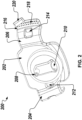
- the gas detector calibration cap 200 includes a cap body 202, a first cap wing 204 and a second cap wing 206.
- the cap body comprises one or more nozzles.
- a nozzle 208 is disposed on the cap body 202.
- the nozzle 208 allows calibration gas (i.e. gas with known concentration) to flow into the gas detector, so that the gas detector can reestablish baselines for sensors.
- the cap body comprises one or more exhaust openings.
- the cap body 202 comprises an exhaust opening 210.
- the exhaust openings allows the calibration gas to leave the gas detector.
- the cap body 202 may further comprise one or more audio openings.
- the cap body 202 includes an audio aperture 212.
- the audio aperture 212 corresponds to the buzzer aperture of the gas detector, allowing sound to be transmitted from within the gas detector to the outside.
- Each of the first cap wing 204 and the second cap wing 206 comprises an opening and an overhang extending through the opening.
- the second cap wing 206 comprise overhang 214 extending thought the opening.
- the overhang in each cap wing provides means for securing the gas detector calibration cap 200 to a gas detector, details of which are described hereinafter.
- the second cap wing 206 further comprise an extended strip 216 extending from the end of the second cap wing 206.
- the extended strip 216 further includes a protrusion 220.
- the protrusion 220 may further comprise a first end and a second end, where the first end is opposite to the second end. The first end may be attached to the extended strip 216, while the second end has a height different than the height of the first end.
- the protrusion 220 is used to open the font shell of the gas detector.
- the height of the second end may be equal to or less than the height of the groove on the edge of the front shell of the gas detector.
- the width of the second end may be equal to or less than the width of the groove on the edge of the front shell of the gas detector.
- the extended strip of the gas detector calibration cap may include one or more dots.
- the extended strip 216 includes dots 218.
- the dots 218 are protrusions from the surface of the extended strip 216. When a user applies force on the extended strip 216 using, for example, a finger, the dots 218 prevent the finger from slipping off the extended strip 216.
- FIG. 3A-3E illustrate various views of an example gas detector calibration cap 300.
- FIG. 3A provides a top view of the gas detector calibration cap 300
- FIG. 3B provides a bottom view of the gas detector calibration cap 300.
- the gas detector calibration cap 300 includes a cap body 302, a first cap wing 304, and a second cap wing 306, similar to the cap body 202, the first cap wing 204, and the second cap wing 206 described above with reference to FIG. 2 , respectively.
- the cap body 302 includes a nozzle 308 and may include an audio aperture 312, and an exhaust opening 310, similar to the nozzle 208, the audio aperture 212, and the exhaust opening 210 as described above with reference to FIG. 2 .
- the first cap wing 304 includes a first overhang 305 extending through a first opening
- the second cap wing 306 includes a second overhang 314 extending through a second opening.
- the first overhang 305 and the second overhang 314 allow the gas detector calibration cap 300 to be securely attached to the gas detector, details of which are described hereinafter.
- the second cap wing 306 includes an extended strip 316, similar to the extended strip 216 described above with reference to FIG. 2 .
- the extended strip 316 includes a protrusion 320, similar to the protrusion 220 described above with reference to FIG. 2 .
- the extended strip 316 may further include dots 318, similar to dots 218 described above with reference to FIG. 2 .
- FIG. 3C a cross-section view of the gas detector calibration cap 300 from the B-B cut line of FIG. 3A is shown.
- FIG. 3C illustrates various components of the gas detector calibration cap 300, including, for example, the nozzle 308, the first overhang 305, the second overhang 314, the extended strip 316 and the protrusion 320.
- FIG. 3D a cross-section view of the gas detector calibration cap 300 from the A-A cut line of FIG. 3B is shown.
- FIG. 3D illustrates various components of the gas detector calibration cap 300, including, for example, the nozzle 308, the extended strip 316, and the protrusion 320.
- the protrusion 320 may be curved.
- the protrusion 320 has a first end and second end, with the first end attached to the extended strip 316.
- the height 321 of the first end is different than the height 322 of the second end.
- the height 322 may be less than or equal to the height of groove on the front shell of the gas detector so that the protrusion 320 can be inserted into the groove.
- FIG. 3E a cross-section view of the gas detector calibration cap 300 from the C-C cut line of FIG. 3A is shown.
- FIG. 3E illustrates various components of the gas detector calibration cap 300, including, for example, the nozzle 308, the cap body 302, and the protrusion 320.
- the system 400 comprises a gas detector 402 and a gas detector calibration cap 404.
- the gas detector may be, for example, the gas detector 100 described above with reference to FIG. 1 .
- the gas detector calibration cap 404 may be, for example, the gas detector calibration cap 200 described above with reference to FIG. 2 , and the gas detector calibration cap 300 described above with reference to FIGS. 3A-3E .
- the gas detector calibration cap 404 is secured to the gas detector 402 using overhangs 406 and 408.
- the calibration gas flows through the nozzle 410 to the gas detector 402.
- the display 412 of the gas detector 402 may display instructions on when to start the gas flow and when to stop the gas flow.
- the LED indicator lights 414 and 416 may indicate the status of calibration.
- FIG. 5 a cross-section view of the system from the cut line B-B of FIG. 4 is shown.
- the overhangs 502 and 504 of the gas detector calibration cap are secured to the slots 506 and 508 of the gas detector, respectively, thereby securing the gas detector calibration cap to the gas detector.
- the nozzle 510 of the gas detector calibration cap allows the calibration gas to flow to the sensors through the exhaust openings 512 of the gas detector.
- the audio aperture 514 of the gas detector calibration cap overlaps the buzzer aperture 516 of the gas detector, such that buzzer sound can be transmitted from inside the gas detector to the outside.
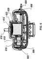
- FIG. 6 another cross-section view of the system from the cut line B-B of FIG. 4 is shown. Similar to those described above with reference to FIG. 5 , the overhangs 602 and 604 of the gas detector calibration cap are secured to the slots 606 and 608 of the gas detector, respectively, thereby securing the gas detector calibration cap to the gas detector.
- the audio aperture 618 of the gas detector calibration cap overlaps the buzzer aperture 616 of the gas detector, such that buzzer sound can be transmitted from inside the gas detector to the outside.
- the gas detector may comprise a protruded portion 620, where the exhaust openings 612 are on top of the protruded portion 620.
- the gas detector calibration cap comprises a corresponding protruded portion 622, allowing the protruded portion 622 to house the protruded portion 620.
- the calibration gas flows through the nozzle 610 of the gas detector calibration cap to the sensors in the gas detector through the exhaust openings 612.
- the gas detector 701 may be, for example, the gas detector 100 described above with reference to FIG. 1 .
- the gas detector 701 comprises a groove 707, similar to the groove 106 described above in reference to FIG. 1 .
- the gas detector calibration cap 703 may be, for example, the gas detector calibration cap 200 described above with reference to FIG. 2 and the gas detector calibration cap 300 described above with reference to FIGS. 3A-3E .
- the gas detector calibration cap 703 comprises a protrusion 705 from an extended strip, similar to the protrusion 220 described above with reference to FIG. 2 and protrusion 320 described above with reference to FIGS. 3A-3E .
- a user may remove the front shell of the gas detector by inserting the protrusion of the extended strip attached to the gas detector calibration cap to the groove on the edge of the front shell of the gas detector, and applying force on the extended strip.
- FIG. 8A illustrates inserting the protrusion 806 of the gas detector calibration cap 804 to the groove 808 of the gas detector 802, and applying force in the direction of 810 on the extended strip to cause the front shell 812 of the gas detector 802 to be dis-attached from the back shell 814.
- FIG. 8B is a cross-section view of FIG. 8A .
- the protrusion 806 of the gas detector calibration cap 804 is aligned with the groove 808, and is inserted into the groove 808 of the gas detector 802.
- a user may apply force in the direction of 810, causing the front shell 812 to be dis-attached from the back shell 814.
- the front shell of the gas detector may comprise a top portion and a bottom portion. When force is applied to the extended strip, only the bottom portion is removed from the gas detector housing.
- a user may install and/or replace one or more sensor(s) and/or filter(s) installed within the gas detector.
- the user may close the gas detector housing by securing the front shell to the back shell, such as through the snap-fit mechanisms described above.
- the user may further attach the gas detector calibration cap to the gas detector after the front shell is attached to the back shell.
- the user may secure the gas detector calibration cap to the gas detector using overhangs from the gas detector calibration cap and slots from the gas detector, similar to those described above.
- any method described above may not necessarily occur in the order depicted in the accompanying diagrams, and in some cases one or more of the steps depicted may occur substantially simultaneously, or additional steps may be involved.
- specific terms are employed herein, they are used in a generic and descriptive sense only and not for purposes of limitation.
Landscapes
- Chemical & Material Sciences (AREA)
- Life Sciences & Earth Sciences (AREA)
- Engineering & Computer Science (AREA)
- Health & Medical Sciences (AREA)
- Analytical Chemistry (AREA)
- Food Science & Technology (AREA)
- Medicinal Chemistry (AREA)
- Physics & Mathematics (AREA)
- Combustion & Propulsion (AREA)
- Biochemistry (AREA)
- General Health & Medical Sciences (AREA)
- General Physics & Mathematics (AREA)
- Immunology (AREA)
- Pathology (AREA)
- Investigating Or Analyzing Materials By The Use Of Fluid Adsorption Or Reactions (AREA)
- Investigating Or Analyzing Materials By The Use Of Electric Means (AREA)
- Sampling And Sample Adjustment (AREA)
Description
- Applicant has identified many deficiencies and problems associated with existing methods, apparatus, and systems related to gas detector and calibration cap for the gap detector. Through applied effort, ingenuity, and innovation, many of these identified deficiencies and problems have been solved by developing solutions that are in accordance with embodiments of the present invention, many examples of which are described in detail herein.
-
CN 204882512 U discloses a portable multi-gas detector and a calibration cap to calibrate the multi-gas detector. -
TW 201221952 A -
US 2014/091939 A1 discloses an alarm enhancing protective cover for safety instruments with optional calibration chamber. - The present invention is defined by the appended claims.
- The accompanying drawings illustrate embodiments of the invention, and, together with the specification, including the general description above and the detailed description which follows, serve to explain the features of the present invention.
-
FIG. 1 illustrates an example gas detector of an example system in accordance with the present invention; -
FIG. 2 illustrates an example gas detector calibration cap of an example system in accordance with the present invention; -
FIGS. 3A ,3B ,3C ,3D , and3E illustrate various views of an example gas detector calibration cap of an example system in accordance with the present invention; -
FIG. 4 illustrates an example system for calibrating a gas detector in accordance with the present invention; -
FIG. 5 illustrates a cross-section view of an example system for calibrating a gas detector in accordance with the present invention; -
FIG. 6 illustrates a cross-section view of an example system for calibrating a gas detector in accordance with the present invention; -
FIG. 7 illustrates an example method, not in accordance with the present invention, of operating an example gas detector and an example gas detector calibration cap of an example system in accordance with the present invention; and -
FIGS. 8A-8B illustrate various views of an example gas detector and an example gas detector calibration cap of an example system in accordance with the present invention, in an example method not in accordance with the present invention. - The present invention now will be described more fully with reference to the accompanying drawings in which some but not all embodiments of the invention are shown.
- The components illustrated in the figures represent components that may be present in various embodiments of the invention described herein. In some instances, the components illustrated in the figures represent components that may not be present in various embodiments of the invention described herein. Accordingly, some embodiments of the present invention may include fewer components, more components, or different combinations of components than those shown in the figures while not departing from the scope of the invention as defined by the appended claims.
- As used herein, terms such as "front," "rear," "top," "bottom," "outside," "inside," "near," "along" and other similar terms are used for explanatory purposes in the examples provided below to describe the relative position of certain devices or portions of devices. It is noted, however, that as devices described herein, or portions thereof, may be attached or utilized in other orientations.
- The term "comprising" means including but not limited to, and should be interpreted in the manner it is typically used in the patent context. Use of broader terms such as comprises, includes, and having should be understood to provide support for narrower terms such as consisting of, consisting essentially of, and comprised substantially of.
- The phrases "in one embodiment," "according to one embodiment," and the like generally mean that the particular feature, structure, or characteristic following the phrase may be included in at least one embodiment of the present invention or more than one embodiment of the present invention. Such phrases do not necessarily refer to the same embodiment.
- The word "example" is used herein to mean "serving as an example, instance, or illustration." Any implementation described herein as "example" is not necessarily to be construed as preferred or advantageous over other implementations.
- The terms "about" or "approximately" or the like, when used with a number, may mean that specific number or a range in proximity to that specific number, as understood by persons of skill in the art field.
- If the specification states a component or feature "may," "can," "could," "should," "would," "preferably," "possibly," "typically," "optionally," "for example," "often," or "might" (or other such language) be included or have a characteristic, that particular component or feature is not required to be included or to have the characteristic. Such component or feature may be optionally included in some embodiments, or it may be excluded.
- The present invention is related generally to systems for gas detectors. More specifically, various embodiments of the present invention describe a system comprising a gas detector and a gas detector calibration cap with an extended strip for the gas detector.
- A gas detector is a device that can detect the presence and/or concentration of various gases and vapors, such as toxic, flammable, or explosive gases, volatile organic compounds (VOCs), humidity, odors, and the like. Gas detection is important in many scenarios. For example, many workers may need to perform work in a confined space, which has limited openings for workers to enter and exit, but not designed for continuous worker occupancy. Such confined spaces may include, for example, storage tanks, ship compartments, process vessels, boilers, sewers, tunnels, and/or like. In confined space, hazardous gas can accumulate to a deadly concentration, resulting in accidents and fatalities. As such, before entering a confined space, a worker may need to test the internal atmosphere with a gas detector for oxygen content, flammable gasses and vapors, potential toxic air contaminants, and the like.
- Gas detectors are generally in two forms: portable gas detector and fixed gas detector. Fixed gas detectors are permanently secured in a location, and can only detect gas within a perimeter of the location. Portable gas detectors allows a user to move the gas detector to a particular location and perform "spot reading" of that location. Portable gas detectors are essential in many areas where gas hazards could occur, because they provide continuously monitoring of an operator's breathing zone, regardless of whether the operator is stationary and moving.
- However, traditional gas detectors are plagued with limitations and deficiencies. For example, gas detectors need to be routinely calibrated to ensure accurate reading, yet traditional gas detectors fail to provide means for calibration.
- In addition, sensor(s) and filter(s) inside the gas detector need to be serviced and replaced for many times during product life of the gas detector. For example, continuous use of the gas detector may cause the filter to deteriorate, and therefore unable to block diffusion of gas. A sensor may have the three to five years of life, while the gas detector (for example, the casing) may have over ten years of product life. As such, the gas detector casing may need to be opened so that filters and sensors within the gas detector can be installed/replaced, yet traditional gas detectors fail to provide an easy, efficient way to open in the casing. For example, a worker may have to use a screw driver to open the gas detector casing, likely causing cracking and breaking of the gas detector casing.
- Systems structured in accordance with various embodiments of the invention provide specific, technical solutions to these technical problems faced by traditional gas detectors. For example, various embodiments of the invention implement a gas detector calibration cap, which provides means for performing accurate calibration of the gas detector. In addition, the gas detector calibration cap includes an extended strip, allowing a worker to easily open the gas detector housing. In other words, the present invention provides means for opening the gas detector housing without breaking the gas detector housing, while integrating such means into the gas detector calibration cap. As a result, the present invention improves the speed and reliability of servicing the gas detector, while eliminating the potential additional cost on special and separate tooling for opening the gas detector housing.
- As such, various embodiments of the present invention overcome challenges faced by traditional gas detectors, details of which are described hereinafter.
- As should be appreciated, various embodiments of the present invention may be implemented as apparatus, systems, and/or the like. For example, embodiments of the present invention include a gas detector and a gas detector calibration cap for calibrating the gas detector.
- Referring now to
FIG. 1 , anexample gas detector 100 is shown. Thegas detector 100 comprises a gas detector housing and one or more sensors or filters disposed within the gas detector housing. - The gas detector housing is formed by a
front shell 102 and aback shell 104. Thefront shell 102 and theback shell 104 may be secured together through snap-fit mechanisms. In some embodiments, thefront shell 102 may comprise flexible member (such as cantilever) extending from the bottom surface around the edge, and theback shell 104 may comprise grooves around its periphery that provide space for the flexible member. In some embodiments, other snap-fit mechanisms may be used, without departing from the scope of the present invention as defined by the appended claims. - As shown in
FIG. 1 , thefront shell 102 further comprises agroove 106 on the edge of thefront shell 102. Thegroove 106 provides mean for disconnecting thefront shell 102 from theback shell 104, details of which are described hereinafter. - As shown in
FIG. 1 , the front shell further comprises one ormore exhaust openings 108. The one ormore exhaust openings 108 allow the gas to pass through thefront shell 102 and to/from inside the gas detector housing, where the one or more sensors are disposed. The gas sensors may include sensors that can detect the presence and concentration of gas such as CO, H2S, O2, CL2, H2, CO-H, SO2, HCN, Os, PH3, NO2, NO, CLOz, NH3, and the like. - The front shell may further comprise one or more displays. For example, as shown in
FIG. 1 , thefront shell 102 comprises aLED display 110. The LED display presents information, such as operation menu of thegas detector 100, instructions for operating thegas detector 100, results of gas detections (for example, type of the gas, concentration of the gas, etc.), and the like. - The front shell may further comprise one or more indicators. For example, as shown in
FIG. 1 , thefront shell 102 comprises LEDindicators LED indicators LED indicator 112 is flashing red, it may indicate that the concentration of certain gas exceeds a threshold. When theLED indicator 114 stays on green, it may indicate that thegas detector 100 is in the process of detecting gas. - The
front shell 102 may further comprise input means, such as one or more buttons, touch sensors, touch bottoms, or the like. For example, as shown inFIG. 1 , thefront shell 102 comprises atouch button 116. Thetouch bottom 116 allows a user to, for example, provide input to select an item from the operation menu displayed on theLED display 110. - In some embodiments, the gas detector may further comprise an infrared (IR) sensor (for example, a passive infrared sensor) for receiving and/or measuring IR light signals.
- The
front shell 102 may further comprise abuzzer aperture 118, allowing sound to be transmitted from within the gas detector housing (for example, from a buzzer). In some embodiments, when thegas detector 100 determines that certain gas exceeds a threshold, the buzzer may emit warning sound through thebuzzer aperture 118 to provide warning for hazardous environment. - The
back shell 104 comprises a slot on each side. For example,FIG. 1 illustrates aslot 120 on one side of theback shell 104. Theslot 120 provides fastening mechanisms for attaching a gas detector calibration cap to the gas detector, details of which are described hereinafter. - In some embodiment, the
front shell 102 may comprise two detachable portions: a top portion and a bottom portion. In this regard, thedisplay 110 andLED indicators buzzer aperture 118,exhaust openings 108, and thegroove 106 may be on the bottom portion. Additionally, theback shell 104 may comprise two corresponding detachable portions: a top portion securing the top portion of thefront shell 102 and a bottom portion securing the bottom portion of thefront shell 102. - In various embodiments, one or more other components may be disposed within the gas detector housing. For example, one or more processors may be in communication with the one or more sensors described above to determine the presence and/or concentration of gas. The one or more processors may include a single core processor, a multi-core processor, and/or the like. The one or more processors may further be in communication with one or more non-transitory storage medium, including, for example, volatile memories, non-volatile memories, and the like. The one or more non-transitory storage medium may be configured to store information, data, content, applications, instructions, or the like for enabling the one or more processors to carry out various functions, such as determining the presence of gas and calculating the concentration of gas.
- Referring now to
FIG. 2 , an example gasdetector calibration cap 200 is shown. The gasdetector calibration cap 200 includes acap body 202, afirst cap wing 204 and asecond cap wing 206. - The cap body comprises one or more nozzles. For example, as shown in
FIG. 2 , anozzle 208 is disposed on thecap body 202. During calibration, thenozzle 208 allows calibration gas (i.e. gas with known concentration) to flow into the gas detector, so that the gas detector can reestablish baselines for sensors. - The cap body comprises one or more exhaust openings. For example, as shown in
FIG. 2 , thecap body 202 comprises anexhaust opening 210. The exhaust openings allows the calibration gas to leave the gas detector. - The
cap body 202 may further comprise one or more audio openings. For example, as shown inFIG. 2 thecap body 202 includes anaudio aperture 212. Theaudio aperture 212 corresponds to the buzzer aperture of the gas detector, allowing sound to be transmitted from within the gas detector to the outside. - Each of the
first cap wing 204 and thesecond cap wing 206 comprises an opening and an overhang extending through the opening. For example, as shown inFIG. 2 , thesecond cap wing 206 compriseoverhang 214 extending thought the opening. The overhang in each cap wing provides means for securing the gasdetector calibration cap 200 to a gas detector, details of which are described hereinafter. - As shown in
FIG. 2 , thesecond cap wing 206 further comprise anextended strip 216 extending from the end of thesecond cap wing 206. Theextended strip 216 further includes aprotrusion 220. Theprotrusion 220 may further comprise a first end and a second end, where the first end is opposite to the second end. The first end may be attached to theextended strip 216, while the second end has a height different than the height of the first end. - As described further in details below, the
protrusion 220 is used to open the font shell of the gas detector. In this regard, the height of the second end may be equal to or less than the height of the groove on the edge of the front shell of the gas detector. The width of the second end may be equal to or less than the width of the groove on the edge of the front shell of the gas detector. - In some embodiments, the extended strip of the gas detector calibration cap may include one or more dots. For example, as shown in
FIG. 2 , theextended strip 216 includesdots 218. Thedots 218 are protrusions from the surface of theextended strip 216. When a user applies force on theextended strip 216 using, for example, a finger, thedots 218 prevent the finger from slipping off theextended strip 216. -
FIG. 3A-3E illustrate various views of an example gasdetector calibration cap 300. Referring now toFIGS. 3A and3B ,FIG. 3A provides a top view of the gasdetector calibration cap 300, andFIG. 3B provides a bottom view of the gasdetector calibration cap 300. - As shown in
FIGS. 3A-3B , the gasdetector calibration cap 300 includes acap body 302, afirst cap wing 304, and asecond cap wing 306, similar to thecap body 202, thefirst cap wing 204, and thesecond cap wing 206 described above with reference toFIG. 2 , respectively. Thecap body 302 includes anozzle 308 and may include anaudio aperture 312, and anexhaust opening 310, similar to thenozzle 208, theaudio aperture 212, and theexhaust opening 210 as described above with reference toFIG. 2 . - The
first cap wing 304 includes afirst overhang 305 extending through a first opening, and thesecond cap wing 306 includes asecond overhang 314 extending through a second opening. Thefirst overhang 305 and thesecond overhang 314 allow the gasdetector calibration cap 300 to be securely attached to the gas detector, details of which are described hereinafter. - Further, the
second cap wing 306 includes anextended strip 316, similar to theextended strip 216 described above with reference toFIG. 2 . Theextended strip 316 includes aprotrusion 320, similar to theprotrusion 220 described above with reference toFIG. 2 . Theextended strip 316 may further includedots 318, similar todots 218 described above with reference toFIG. 2 . - Referring to
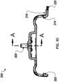
FIG. 3C , a cross-section view of the gasdetector calibration cap 300 from the B-B cut line ofFIG. 3A is shown.FIG. 3C illustrates various components of the gasdetector calibration cap 300, including, for example, thenozzle 308, thefirst overhang 305, thesecond overhang 314, theextended strip 316 and theprotrusion 320. - Referring to
FIG. 3D , a cross-section view of the gasdetector calibration cap 300 from the A-A cut line ofFIG. 3B is shown.FIG. 3D illustrates various components of the gasdetector calibration cap 300, including, for example, thenozzle 308, theextended strip 316, and theprotrusion 320. As shown inFIG. 3D , theprotrusion 320 may be curved. Theprotrusion 320 has a first end and second end, with the first end attached to theextended strip 316. Theheight 321 of the first end is different than theheight 322 of the second end. For example, theheight 322 may be less than or equal to the height of groove on the front shell of the gas detector so that theprotrusion 320 can be inserted into the groove. - Referring to
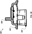
FIG. 3E , a cross-section view of the gasdetector calibration cap 300 from the C-C cut line ofFIG. 3A is shown.FIG. 3E illustrates various components of the gasdetector calibration cap 300, including, for example, thenozzle 308, thecap body 302, and theprotrusion 320. - In accordance with various embodiments of the present invention, a system for calibrating a gas detector is provided. For example, as shown in
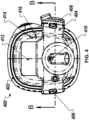
FIG. 4 , thesystem 400 comprises agas detector 402 and a gasdetector calibration cap 404. The gas detector may be, for example, thegas detector 100 described above with reference toFIG. 1 . The gasdetector calibration cap 404 may be, for example, the gasdetector calibration cap 200 described above with reference toFIG. 2 , and the gasdetector calibration cap 300 described above with reference toFIGS. 3A-3E . - As shown in
FIG. 4 , the gasdetector calibration cap 404 is secured to thegas detector 402 usingoverhangs nozzle 410 to thegas detector 402. Thedisplay 412 of thegas detector 402 may display instructions on when to start the gas flow and when to stop the gas flow. TheLED indicator lights - Referring now to
FIG. 5 , a cross-section view of the system from the cut line B-B ofFIG. 4 is shown. As shown inFIG. 5 , theoverhangs slots nozzle 510 of the gas detector calibration cap allows the calibration gas to flow to the sensors through theexhaust openings 512 of the gas detector. Theaudio aperture 514 of the gas detector calibration cap overlaps thebuzzer aperture 516 of the gas detector, such that buzzer sound can be transmitted from inside the gas detector to the outside. - Referring now to
FIG. 6 , another cross-section view of the system from the cut line B-B ofFIG. 4 is shown. Similar to those described above with reference toFIG. 5 , theoverhangs slots audio aperture 618 of the gas detector calibration cap overlaps thebuzzer aperture 616 of the gas detector, such that buzzer sound can be transmitted from inside the gas detector to the outside. - Further, as shown in
FIG. 6 , the gas detector may comprise a protrudedportion 620, where theexhaust openings 612 are on top of the protrudedportion 620. In this regard, the gas detector calibration cap comprises a corresponding protrudedportion 622, allowing the protrudedportion 622 to house the protrudedportion 620. As such, the calibration gas flows through thenozzle 610 of the gas detector calibration cap to the sensors in the gas detector through theexhaust openings 612. - Referring now to
FIG. 7 , agas detector 701 and a gasdetector calibration cap 703 are shown. Thegas detector 701 may be, for example, thegas detector 100 described above with reference toFIG. 1 . For example, thegas detector 701 comprises agroove 707, similar to thegroove 106 described above in reference toFIG. 1 . - The gas
detector calibration cap 703 may be, for example, the gasdetector calibration cap 200 described above with reference toFIG. 2 and the gasdetector calibration cap 300 described above with reference toFIGS. 3A-3E . The gasdetector calibration cap 703 comprises aprotrusion 705 from an extended strip, similar to theprotrusion 220 described above with reference toFIG. 2 andprotrusion 320 described above with reference toFIGS. 3A-3E . - Referring now to
FIGS. 8A-8B , a user may remove the front shell of the gas detector by inserting the protrusion of the extended strip attached to the gas detector calibration cap to the groove on the edge of the front shell of the gas detector, and applying force on the extended strip. - For example,
FIG. 8A illustrates inserting theprotrusion 806 of the gasdetector calibration cap 804 to thegroove 808 of thegas detector 802, and applying force in the direction of 810 on the extended strip to cause thefront shell 812 of thegas detector 802 to be dis-attached from theback shell 814. -
FIG. 8B is a cross-section view ofFIG. 8A . As shown inFIG. 8B , theprotrusion 806 of the gasdetector calibration cap 804 is aligned with thegroove 808, and is inserted into thegroove 808 of thegas detector 802. After inserting theprotrusion 806, a user may apply force in the direction of 810, causing thefront shell 812 to be dis-attached from theback shell 814. - As described above, the front shell of the gas detector may comprise a top portion and a bottom portion. When force is applied to the extended strip, only the bottom portion is removed from the gas detector housing.
- After the font shell is remove from the back shell, a user may install and/or replace one or more sensor(s) and/or filter(s) installed within the gas detector. The user may close the gas detector housing by securing the front shell to the back shell, such as through the snap-fit mechanisms described above.
- The user may further attach the gas detector calibration cap to the gas detector after the front shell is attached to the back shell. In this regard, the user may secure the gas detector calibration cap to the gas detector using overhangs from the gas detector calibration cap and slots from the gas detector, similar to those described above.
- Furthermore, any advantages and features described above may relate to specific embodiments, but shall not limit the application of such issued claims to processes and structures accomplishing any or all of the above advantages or having any or all of the above features.
- Also, techniques, systems, subsystems, and methods described and illustrated as discrete or separate may be combined or integrated with other systems, modules, techniques, or methods without departing from the scope of the present invention. Other items shown or discussed as directly coupled or communicating with each other may be indirectly coupled or communicating through some interface, device, or intermediate component, whether electrically, mechanically, or otherwise. Other examples of changes, substitutions, and alterations are ascertainable by one skilled in the art and could be made without departing from the scope of the present invention as defined by the appended claims.
- Many modifications and other embodiments of the invention set forth herein will come to mind to one skilled in the art to which these embodiments pertain having the benefit of teachings presented in the foregoing descriptions and the associated figures. Although the figures only show certain components of the apparatus and systems described herein, it is understood that various other components may be used in conjunction. Therefore, it is to be understood that the invention is not to be limited to the specific embodiments disclosed and that modifications and other embodiments are intended to be included within the scope of the appended claims. For example, the various elements or components may be combined or integrated in another system or certain features may be omitted or not implemented. Moreover, the steps in any method described above may not necessarily occur in the order depicted in the accompanying diagrams, and in some cases one or more of the steps depicted may occur substantially simultaneously, or additional steps may be involved. Although specific terms are employed herein, they are used in a generic and descriptive sense only and not for purposes of limitation.
Claims (6)
- A system comprising a gas detector (100, 402, 701, 802) and a gas detector calibration cap (200, 300, 404, 703, 804) for calibrating said gas detector (100, 402, 701, 802),wherein the gas detector (100, 402, 701, 802) comprises:
a gas detector housing, comprising:a front shell (102, 812) comprising one or more exhaust opening (108,512,612) and a groove (106, 808) on an edge of the front shell (102, 812); anda back shell (104, 814) connected to the front shell (102, 812) comprising a first slot (120, 506, 606) on a first side of the back shell (104, 814), a second slot (120, 508, 608) on a second side of the back shell (108, 814);and one or more sensors or filters disposed within the gas detector housing; andwherein the gas detector calibration cap (200, 300, 404, 703, 804) comprises:a cap body (202, 302), comprising a nozzle (208, 308, 410, 510, 610) disposed on the cap body (202, 302) and an exhaust opening (108, 210, 310, 512, 612);a first cap wing (204, 304) connected to the cap body (202, 302), comprising a first opening and a first overhang (305) extending through the first opening;a second cap wing (206, 306) connected to the cap body (202, 302), comprising:a second opening;a second overhang (214, 314) extending through the second opening; andan extended strip (216, 316) attached to an end of the second cap wing (206, 306), characterized in that the extended strip (216, 316) comprises a protrusion (220, 320, 806) configured for opening the front shell (102, 812) of the gas detector (100, 402, 701, 802) by inserting said protrusion (220, 320, 806) in said groove (106, 808) on the edge of the front shell (102, 812) of the gas detector (100, 402, 701, 802) and by applying force on said extended strip (216, 316). - The system according to Claim 1, wherein the protrusion (220, 320, 806) comprises a first end and a second end, wherein the first end is attached to the extended strip (216, 316), wherein a height of the first end is different than a height of the second end.
- The system according to Claim 2, wherein the height of the second end is less than or equal to a height of said groove (106, 808) on the edge of the front shell (102, 812) of the gas detector (100, 402, 701, 802).
- The system according to Claim 1, wherein a width of the protrusion (220, 320, 806) of the extended strip (216, 316) is less than or equal to a width of said groove (106, 808) on the edge of the front shell (102, 812) of the gas detector (100, 402, 701, 802).
- The system according to Claim 1, wherein the extended strip (216, 316) further comprises one or more dots (218) disposed on a surface of the extended strip (216, 316).
- The system according to Claim 1, wherein the cap body (202, 302) further comprises an audio opening.
Applications Claiming Priority (1)
| Application Number | Priority Date | Filing Date | Title |
|---|---|---|---|
| PCT/CN2018/109236 WO2020069633A1 (en) | 2018-10-02 | 2018-10-02 | Gas detector calibration cap with an extended strip |
Publications (3)
| Publication Number | Publication Date |
|---|---|
| EP3861338A1 EP3861338A1 (en) | 2021-08-11 |
| EP3861338A4 EP3861338A4 (en) | 2022-04-27 |
| EP3861338B1 true EP3861338B1 (en) | 2023-04-26 |
Family
ID=70054470
Family Applications (1)
| Application Number | Title | Priority Date | Filing Date |
|---|---|---|---|
| EP18936170.2A Active EP3861338B1 (en) | 2018-10-02 | 2018-10-02 | Gas detector calibration cap with an extended strip |
Country Status (5)
| Country | Link |
|---|---|
| US (1) | US11867674B2 (en) |
| EP (1) | EP3861338B1 (en) |
| CN (1) | CN112673254B (en) |
| AU (1) | AU2018444262B2 (en) |
| WO (1) | WO2020069633A1 (en) |
Families Citing this family (4)
| Publication number | Priority date | Publication date | Assignee | Title |
|---|---|---|---|---|
| US12387570B2 (en) * | 2021-06-23 | 2025-08-12 | Bank Of America Corporation | Artificial intelligence (AI)-based security systems for monitoring and securing physical locations |
| US11735017B2 (en) | 2021-06-23 | 2023-08-22 | Bank Of America Corporation | Artificial intelligence (AI)-based security systems for monitoring and securing physical locations |
| US11954990B2 (en) | 2021-06-23 | 2024-04-09 | Bank Of America Corporation | Artificial intelligence (AI)-based security systems for monitoring and securing physical locations |
| USD1093186S1 (en) * | 2024-04-30 | 2025-09-16 | Minyi Zeng | Gas detector |
Family Cites Families (24)
| Publication number | Priority date | Publication date | Assignee | Title |
|---|---|---|---|---|
| US6244093B1 (en) | 1997-03-14 | 2001-06-12 | Kaushik K. Parekh | Method and apparatus for calibrating an air monitor using a flow matching valve |
| US7275411B2 (en) * | 2004-10-19 | 2007-10-02 | Industrial Scientific Corporation | Apparatus and method for testing gas detection instruments |
| US7281404B2 (en) * | 2004-10-19 | 2007-10-16 | Industrial Scientific Corporation | Apparatus and method for testing gas detection instruments |
| CN103196522A (en) | 2005-01-18 | 2013-07-10 | 流体元件国际公司 | Flowmeter in-situ calibration verification system |
| US7174766B2 (en) | 2005-05-24 | 2007-02-13 | Honeywell International Inc. | Calibration device for carbon dioxide sensor |
| JP4676363B2 (en) | 2006-03-15 | 2011-04-27 | 理研計器株式会社 | Portable gas alarm |
| JP4691579B2 (en) | 2008-05-26 | 2011-06-01 | 理研計器株式会社 | Portable gas alarm |
| TWI481866B (en) | 2011-08-19 | 2015-04-21 | Ind Tech Res Inst | Gas detector and calibration method thereof |
| CN104903953B (en) | 2012-10-02 | 2018-05-15 | 工业科技有限公司 | Alarm Reinforced Cover with Optional Calibration Chamber for Safety Devices |
| CN105699589A (en) | 2014-11-23 | 2016-06-22 | 西安奥赛福科技有限公司 | Portable gas detector |
| CN204882512U (en) | 2015-08-05 | 2015-12-16 | 深圳市南油诺安电子有限公司 | Portable multi -gas detector |
| EP3136071B1 (en) | 2015-08-25 | 2018-03-28 | The Swatch Group Research and Development Ltd. | Device and method for calibrating a device for measuring altitude |
| CN205607948U (en) * | 2015-10-09 | 2016-09-28 | 扬中市南方矿用电器有限公司 | Methane carbon monoxide detector alarm |
| CN205301290U (en) * | 2016-01-11 | 2016-06-08 | 北京安赛克科技有限公司 | Pentahapto detector of personally experiencing sth. part of body at a stretch |
| CN205426891U (en) * | 2016-03-14 | 2016-08-03 | 清流亮剑环保技术开发有限公司 | A empty gas detection survey device for desulfurization is removed dust |
| KR101797637B1 (en) | 2016-03-28 | 2017-11-20 | 주식회사아이센랩 | Calibration device and apparatus for analysing gas component having the same |
| US10295515B2 (en) | 2016-06-16 | 2019-05-21 | Honeywell International Inc. | System and method for calibration of volatile organic compound detecting instruments |
| KR20180001860A (en) | 2016-06-28 | 2018-01-05 | 주식회사 포스코 | Apparatus for manufacturing molten irons and method for manufacturing molten irons using the same |
| CN205982213U (en) | 2016-07-20 | 2017-02-22 | 霍尼韦尔国际公司 | A sizing stop for photoionization detector |
| KR20180001860U (en) * | 2016-12-13 | 2018-06-21 | 여동수 | Lid for airtight vessel |
| DE102017104367A1 (en) | 2017-03-02 | 2018-09-06 | Bizerba SE & Co. KG | Load cell for a balance |
| CN206583890U (en) * | 2017-03-28 | 2017-10-24 | 张银虎 | The air detecting device of replaceable sensor |
| CN206756789U (en) * | 2017-06-02 | 2017-12-15 | 青岛明华电子仪器有限公司 | A kind of more gas detecting instruments |
| US11360065B2 (en) * | 2018-03-16 | 2022-06-14 | Teledyne Flir Detection, Inc. | Calibration systems and methods for analyte detectors |
-
2018
- 2018-10-02 WO PCT/CN2018/109236 patent/WO2020069633A1/en not_active Ceased
- 2018-10-02 AU AU2018444262A patent/AU2018444262B2/en active Active
- 2018-10-02 CN CN201880097349.8A patent/CN112673254B/en active Active
- 2018-10-02 EP EP18936170.2A patent/EP3861338B1/en active Active
- 2018-10-02 US US17/278,566 patent/US11867674B2/en active Active
Also Published As
| Publication number | Publication date |
|---|---|
| CN112673254A (en) | 2021-04-16 |
| AU2018444262A1 (en) | 2021-05-13 |
| AU2018444262B2 (en) | 2022-03-10 |
| WO2020069633A1 (en) | 2020-04-09 |
| US20210356448A1 (en) | 2021-11-18 |
| CN112673254B (en) | 2023-06-23 |
| EP3861338A4 (en) | 2022-04-27 |
| EP3861338A1 (en) | 2021-08-11 |
| US11867674B2 (en) | 2024-01-09 |
Similar Documents
| Publication | Publication Date | Title |
|---|---|---|
| AU2018444262B2 (en) | Gas detector calibration cap with an extended strip | |
| US11692985B2 (en) | Gas identification by measuring stain development at multiple specific wavelength regions with narrow band optical sensors | |
| Askim et al. | An optoelectronic nose for identification of explosives | |
| EP3267004A1 (en) | Venting device provided with oxygen sensor | |
| US20120137586A1 (en) | Through-Door Arm Access Porthole Assembly | |
| EP3428607B1 (en) | Leak detection method for open emission analysis, and open emission analysis device | |
| US20180164264A1 (en) | Filter for visual gas sensor | |
| EP2770490A1 (en) | Systems and methods for traffic prioritization | |
| US20040141879A1 (en) | System and method for detection of a target substance | |
| US6622556B1 (en) | Total temperature probe with complimentary sensor cavity | |
| EP4188214B1 (en) | Method and system for determination and classification of intoxicating substance in a breath sample facilitated by a user interaction scheme | |
| US20150297117A1 (en) | Standard alcohol gas cartridge for a drunkometer | |
| US20180235581A1 (en) | Remote air detector of the alcohol content or other chemical or natural product, harmful to the mental-physical state of a person driving a means of transport | |
| CN206756789U (en) | A kind of more gas detecting instruments | |
| EP3006098A1 (en) | Gas separation cartridge | |
| CN103733029B (en) | Protective housing for sensors used to detect analytes | |
| CN106198882A (en) | Gas-detecting device | |
| CN103645070B (en) | A kind of toy respiration test is used radial without reflux gas sampling apparatus | |
| SE1250673A1 (en) | Apparatus and method for heating a device for alcohol exhalation samples | |
| EP4239609A1 (en) | Disaster prevention device | |
| WO2007009159A1 (en) | Atmospheric safety monitoring device | |
| CN211179543U (en) | Poisonous and harmful gas detector | |
| CN110736745B (en) | Toxic and harmful gas detector | |
| CN216187760U (en) | Protein detect reagent box convenient to carry | |
| JP3120770U (en) | Name plate for helium leak detector |
Legal Events
| Date | Code | Title | Description |
|---|---|---|---|
| STAA | Information on the status of an ep patent application or granted ep patent |
Free format text: STATUS: THE INTERNATIONAL PUBLICATION HAS BEEN MADE |
|
| PUAI | Public reference made under article 153(3) epc to a published international application that has entered the european phase |
Free format text: ORIGINAL CODE: 0009012 |
|
| STAA | Information on the status of an ep patent application or granted ep patent |
Free format text: STATUS: REQUEST FOR EXAMINATION WAS MADE |
|
| 17P | Request for examination filed |
Effective date: 20210416 |
|
| AK | Designated contracting states |
Kind code of ref document: A1 Designated state(s): AL AT BE BG CH CY CZ DE DK EE ES FI FR GB GR HR HU IE IS IT LI LT LU LV MC MK MT NL NO PL PT RO RS SE SI SK SM TR |
|
| DAV | Request for validation of the european patent (deleted) | ||
| DAX | Request for extension of the european patent (deleted) | ||
| A4 | Supplementary search report drawn up and despatched |
Effective date: 20220329 |
|
| RIC1 | Information provided on ipc code assigned before grant |
Ipc: G01N 33/00 20060101AFI20220323BHEP |
|
| GRAP | Despatch of communication of intention to grant a patent |
Free format text: ORIGINAL CODE: EPIDOSNIGR1 |
|
| STAA | Information on the status of an ep patent application or granted ep patent |
Free format text: STATUS: GRANT OF PATENT IS INTENDED |
|
| INTG | Intention to grant announced |
Effective date: 20221121 |
|
| GRAS | Grant fee paid |
Free format text: ORIGINAL CODE: EPIDOSNIGR3 |
|
| GRAA | (expected) grant |
Free format text: ORIGINAL CODE: 0009210 |
|
| STAA | Information on the status of an ep patent application or granted ep patent |
Free format text: STATUS: THE PATENT HAS BEEN GRANTED |
|
| AK | Designated contracting states |
Kind code of ref document: B1 Designated state(s): AL AT BE BG CH CY CZ DE DK EE ES FI FR GB GR HR HU IE IS IT LI LT LU LV MC MK MT NL NO PL PT RO RS SE SI SK SM TR |
|
| REG | Reference to a national code |
Ref country code: GB Ref legal event code: FG4D |
|
| REG | Reference to a national code |
Ref country code: CH Ref legal event code: EP |
|
| REG | Reference to a national code |
Ref country code: DE Ref legal event code: R096 Ref document number: 602018049079 Country of ref document: DE |
|
| REG | Reference to a national code |
Ref country code: AT Ref legal event code: REF Ref document number: 1563181 Country of ref document: AT Kind code of ref document: T Effective date: 20230515 |
|
| REG | Reference to a national code |
Ref country code: IE Ref legal event code: FG4D |
|
| REG | Reference to a national code |
Ref country code: LT Ref legal event code: MG9D |
|
| REG | Reference to a national code |
Ref country code: NL Ref legal event code: MP Effective date: 20230426 |
|
| REG | Reference to a national code |
Ref country code: AT Ref legal event code: MK05 Ref document number: 1563181 Country of ref document: AT Kind code of ref document: T Effective date: 20230426 |
|
| PG25 | Lapsed in a contracting state [announced via postgrant information from national office to epo] |
Ref country code: NL Free format text: LAPSE BECAUSE OF FAILURE TO SUBMIT A TRANSLATION OF THE DESCRIPTION OR TO PAY THE FEE WITHIN THE PRESCRIBED TIME-LIMIT Effective date: 20230426 |
|
| PG25 | Lapsed in a contracting state [announced via postgrant information from national office to epo] |
Ref country code: SE Free format text: LAPSE BECAUSE OF FAILURE TO SUBMIT A TRANSLATION OF THE DESCRIPTION OR TO PAY THE FEE WITHIN THE PRESCRIBED TIME-LIMIT Effective date: 20230426 Ref country code: PT Free format text: LAPSE BECAUSE OF FAILURE TO SUBMIT A TRANSLATION OF THE DESCRIPTION OR TO PAY THE FEE WITHIN THE PRESCRIBED TIME-LIMIT Effective date: 20230828 Ref country code: NO Free format text: LAPSE BECAUSE OF FAILURE TO SUBMIT A TRANSLATION OF THE DESCRIPTION OR TO PAY THE FEE WITHIN THE PRESCRIBED TIME-LIMIT Effective date: 20230726 Ref country code: ES Free format text: LAPSE BECAUSE OF FAILURE TO SUBMIT A TRANSLATION OF THE DESCRIPTION OR TO PAY THE FEE WITHIN THE PRESCRIBED TIME-LIMIT Effective date: 20230426 Ref country code: AT Free format text: LAPSE BECAUSE OF FAILURE TO SUBMIT A TRANSLATION OF THE DESCRIPTION OR TO PAY THE FEE WITHIN THE PRESCRIBED TIME-LIMIT Effective date: 20230426 |
|
| PG25 | Lapsed in a contracting state [announced via postgrant information from national office to epo] |
Ref country code: RS Free format text: LAPSE BECAUSE OF FAILURE TO SUBMIT A TRANSLATION OF THE DESCRIPTION OR TO PAY THE FEE WITHIN THE PRESCRIBED TIME-LIMIT Effective date: 20230426 Ref country code: PL Free format text: LAPSE BECAUSE OF FAILURE TO SUBMIT A TRANSLATION OF THE DESCRIPTION OR TO PAY THE FEE WITHIN THE PRESCRIBED TIME-LIMIT Effective date: 20230426 Ref country code: LV Free format text: LAPSE BECAUSE OF FAILURE TO SUBMIT A TRANSLATION OF THE DESCRIPTION OR TO PAY THE FEE WITHIN THE PRESCRIBED TIME-LIMIT Effective date: 20230426 Ref country code: LT Free format text: LAPSE BECAUSE OF FAILURE TO SUBMIT A TRANSLATION OF THE DESCRIPTION OR TO PAY THE FEE WITHIN THE PRESCRIBED TIME-LIMIT Effective date: 20230426 Ref country code: IS Free format text: LAPSE BECAUSE OF FAILURE TO SUBMIT A TRANSLATION OF THE DESCRIPTION OR TO PAY THE FEE WITHIN THE PRESCRIBED TIME-LIMIT Effective date: 20230826 Ref country code: HR Free format text: LAPSE BECAUSE OF FAILURE TO SUBMIT A TRANSLATION OF THE DESCRIPTION OR TO PAY THE FEE WITHIN THE PRESCRIBED TIME-LIMIT Effective date: 20230426 Ref country code: GR Free format text: LAPSE BECAUSE OF FAILURE TO SUBMIT A TRANSLATION OF THE DESCRIPTION OR TO PAY THE FEE WITHIN THE PRESCRIBED TIME-LIMIT Effective date: 20230727 |
|
| PG25 | Lapsed in a contracting state [announced via postgrant information from national office to epo] |
Ref country code: FI Free format text: LAPSE BECAUSE OF FAILURE TO SUBMIT A TRANSLATION OF THE DESCRIPTION OR TO PAY THE FEE WITHIN THE PRESCRIBED TIME-LIMIT Effective date: 20230426 |
|
| PG25 | Lapsed in a contracting state [announced via postgrant information from national office to epo] |
Ref country code: SK Free format text: LAPSE BECAUSE OF FAILURE TO SUBMIT A TRANSLATION OF THE DESCRIPTION OR TO PAY THE FEE WITHIN THE PRESCRIBED TIME-LIMIT Effective date: 20230426 |
|
| REG | Reference to a national code |
Ref country code: DE Ref legal event code: R097 Ref document number: 602018049079 Country of ref document: DE |
|
| PG25 | Lapsed in a contracting state [announced via postgrant information from national office to epo] |
Ref country code: SM Free format text: LAPSE BECAUSE OF FAILURE TO SUBMIT A TRANSLATION OF THE DESCRIPTION OR TO PAY THE FEE WITHIN THE PRESCRIBED TIME-LIMIT Effective date: 20230426 Ref country code: SK Free format text: LAPSE BECAUSE OF FAILURE TO SUBMIT A TRANSLATION OF THE DESCRIPTION OR TO PAY THE FEE WITHIN THE PRESCRIBED TIME-LIMIT Effective date: 20230426 Ref country code: RO Free format text: LAPSE BECAUSE OF FAILURE TO SUBMIT A TRANSLATION OF THE DESCRIPTION OR TO PAY THE FEE WITHIN THE PRESCRIBED TIME-LIMIT Effective date: 20230426 Ref country code: EE Free format text: LAPSE BECAUSE OF FAILURE TO SUBMIT A TRANSLATION OF THE DESCRIPTION OR TO PAY THE FEE WITHIN THE PRESCRIBED TIME-LIMIT Effective date: 20230426 Ref country code: DK Free format text: LAPSE BECAUSE OF FAILURE TO SUBMIT A TRANSLATION OF THE DESCRIPTION OR TO PAY THE FEE WITHIN THE PRESCRIBED TIME-LIMIT Effective date: 20230426 Ref country code: CZ Free format text: LAPSE BECAUSE OF FAILURE TO SUBMIT A TRANSLATION OF THE DESCRIPTION OR TO PAY THE FEE WITHIN THE PRESCRIBED TIME-LIMIT Effective date: 20230426 |
|
| PLBE | No opposition filed within time limit |
Free format text: ORIGINAL CODE: 0009261 |
|
| STAA | Information on the status of an ep patent application or granted ep patent |
Free format text: STATUS: NO OPPOSITION FILED WITHIN TIME LIMIT |
|
| 26N | No opposition filed |
Effective date: 20240129 |
|
| PG25 | Lapsed in a contracting state [announced via postgrant information from national office to epo] |
Ref country code: SI Free format text: LAPSE BECAUSE OF FAILURE TO SUBMIT A TRANSLATION OF THE DESCRIPTION OR TO PAY THE FEE WITHIN THE PRESCRIBED TIME-LIMIT Effective date: 20230426 |
|
| PG25 | Lapsed in a contracting state [announced via postgrant information from national office to epo] |
Ref country code: SI Free format text: LAPSE BECAUSE OF FAILURE TO SUBMIT A TRANSLATION OF THE DESCRIPTION OR TO PAY THE FEE WITHIN THE PRESCRIBED TIME-LIMIT Effective date: 20230426 Ref country code: IT Free format text: LAPSE BECAUSE OF FAILURE TO SUBMIT A TRANSLATION OF THE DESCRIPTION OR TO PAY THE FEE WITHIN THE PRESCRIBED TIME-LIMIT Effective date: 20230426 Ref country code: MC Free format text: LAPSE BECAUSE OF FAILURE TO SUBMIT A TRANSLATION OF THE DESCRIPTION OR TO PAY THE FEE WITHIN THE PRESCRIBED TIME-LIMIT Effective date: 20230426 |
|
| REG | Reference to a national code |
Ref country code: CH Ref legal event code: PL |
|
| REG | Reference to a national code |
Ref country code: BE Ref legal event code: MM Effective date: 20231031 |
|
| PG25 | Lapsed in a contracting state [announced via postgrant information from national office to epo] |
Ref country code: LU Free format text: LAPSE BECAUSE OF NON-PAYMENT OF DUE FEES Effective date: 20231002 |
|
| PG25 | Lapsed in a contracting state [announced via postgrant information from national office to epo] |
Ref country code: LU Free format text: LAPSE BECAUSE OF NON-PAYMENT OF DUE FEES Effective date: 20231002 |
|
| PG25 | Lapsed in a contracting state [announced via postgrant information from national office to epo] |
Ref country code: CH Free format text: LAPSE BECAUSE OF NON-PAYMENT OF DUE FEES Effective date: 20231031 |
|
| PG25 | Lapsed in a contracting state [announced via postgrant information from national office to epo] |
Ref country code: CH Free format text: LAPSE BECAUSE OF NON-PAYMENT OF DUE FEES Effective date: 20231031 |
|
| PG25 | Lapsed in a contracting state [announced via postgrant information from national office to epo] |
Ref country code: BE Free format text: LAPSE BECAUSE OF NON-PAYMENT OF DUE FEES Effective date: 20231031 |
|
| PG25 | Lapsed in a contracting state [announced via postgrant information from national office to epo] |
Ref country code: IE Free format text: LAPSE BECAUSE OF NON-PAYMENT OF DUE FEES Effective date: 20231002 |
|
| PG25 | Lapsed in a contracting state [announced via postgrant information from national office to epo] |
Ref country code: IE Free format text: LAPSE BECAUSE OF NON-PAYMENT OF DUE FEES Effective date: 20231002 |
|
| PG25 | Lapsed in a contracting state [announced via postgrant information from national office to epo] |
Ref country code: BG Free format text: LAPSE BECAUSE OF FAILURE TO SUBMIT A TRANSLATION OF THE DESCRIPTION OR TO PAY THE FEE WITHIN THE PRESCRIBED TIME-LIMIT Effective date: 20230426 |
|
| PG25 | Lapsed in a contracting state [announced via postgrant information from national office to epo] |
Ref country code: BG Free format text: LAPSE BECAUSE OF FAILURE TO SUBMIT A TRANSLATION OF THE DESCRIPTION OR TO PAY THE FEE WITHIN THE PRESCRIBED TIME-LIMIT Effective date: 20230426 |
|
| PG25 | Lapsed in a contracting state [announced via postgrant information from national office to epo] |
Ref country code: CY Free format text: LAPSE BECAUSE OF FAILURE TO SUBMIT A TRANSLATION OF THE DESCRIPTION OR TO PAY THE FEE WITHIN THE PRESCRIBED TIME-LIMIT; INVALID AB INITIO Effective date: 20181002 |
|
| PG25 | Lapsed in a contracting state [announced via postgrant information from national office to epo] |
Ref country code: HU Free format text: LAPSE BECAUSE OF FAILURE TO SUBMIT A TRANSLATION OF THE DESCRIPTION OR TO PAY THE FEE WITHIN THE PRESCRIBED TIME-LIMIT; INVALID AB INITIO Effective date: 20181002 |
|
| PG25 | Lapsed in a contracting state [announced via postgrant information from national office to epo] |
Ref country code: TR Free format text: LAPSE BECAUSE OF FAILURE TO SUBMIT A TRANSLATION OF THE DESCRIPTION OR TO PAY THE FEE WITHIN THE PRESCRIBED TIME-LIMIT Effective date: 20230426 |
|
| PGFP | Annual fee paid to national office [announced via postgrant information from national office to epo] |
Ref country code: DE Payment date: 20251028 Year of fee payment: 8 |
|
| PGFP | Annual fee paid to national office [announced via postgrant information from national office to epo] |
Ref country code: GB Payment date: 20251023 Year of fee payment: 8 |
|
| PGFP | Annual fee paid to national office [announced via postgrant information from national office to epo] |
Ref country code: FR Payment date: 20251027 Year of fee payment: 8 |