EP3861191B1 - Gate valve assembly for a subsea workover system - Google Patents
Gate valve assembly for a subsea workover system Download PDFInfo
- Publication number
- EP3861191B1 EP3861191B1 EP19783291.8A EP19783291A EP3861191B1 EP 3861191 B1 EP3861191 B1 EP 3861191B1 EP 19783291 A EP19783291 A EP 19783291A EP 3861191 B1 EP3861191 B1 EP 3861191B1
- Authority
- EP
- European Patent Office
- Prior art keywords
- gate valve
- recessed part
- valve member
- flow path
- gate
- Prior art date
- Legal status (The legal status is an assumption and is not a legal conclusion. Google has not performed a legal analysis and makes no representation as to the accuracy of the status listed.)
- Active
Links
Images



Classifications
-
- E—FIXED CONSTRUCTIONS
- E21—EARTH OR ROCK DRILLING; MINING
- E21B—EARTH OR ROCK DRILLING; OBTAINING OIL, GAS, WATER, SOLUBLE OR MELTABLE MATERIALS OR A SLURRY OF MINERALS FROM WELLS
- E21B34/00—Valve arrangements for boreholes or wells
- E21B34/02—Valve arrangements for boreholes or wells in well heads
- E21B34/04—Valve arrangements for boreholes or wells in well heads in underwater well heads
-
- E—FIXED CONSTRUCTIONS
- E21—EARTH OR ROCK DRILLING; MINING
- E21B—EARTH OR ROCK DRILLING; OBTAINING OIL, GAS, WATER, SOLUBLE OR MELTABLE MATERIALS OR A SLURRY OF MINERALS FROM WELLS
- E21B34/00—Valve arrangements for boreholes or wells
- E21B34/02—Valve arrangements for boreholes or wells in well heads
-
- E—FIXED CONSTRUCTIONS
- E21—EARTH OR ROCK DRILLING; MINING
- E21B—EARTH OR ROCK DRILLING; OBTAINING OIL, GAS, WATER, SOLUBLE OR MELTABLE MATERIALS OR A SLURRY OF MINERALS FROM WELLS
- E21B29/00—Cutting or destroying pipes, packers, plugs or wire lines, located in boreholes or wells, e.g. cutting of damaged pipes, of windows; Deforming of pipes in boreholes or wells; Reconditioning of well casings while in the ground
- E21B29/04—Cutting of wire lines or the like
-
- E—FIXED CONSTRUCTIONS
- E21—EARTH OR ROCK DRILLING; MINING
- E21B—EARTH OR ROCK DRILLING; OBTAINING OIL, GAS, WATER, SOLUBLE OR MELTABLE MATERIALS OR A SLURRY OF MINERALS FROM WELLS
- E21B33/00—Sealing or packing boreholes or wells
- E21B33/02—Surface sealing or packing
- E21B33/03—Well heads; Setting-up thereof
- E21B33/06—Blow-out preventers, i.e. apparatus closing around a drill pipe, e.g. annular blow-out preventers
-
- F—MECHANICAL ENGINEERING; LIGHTING; HEATING; WEAPONS; BLASTING
- F16—ENGINEERING ELEMENTS AND UNITS; GENERAL MEASURES FOR PRODUCING AND MAINTAINING EFFECTIVE FUNCTIONING OF MACHINES OR INSTALLATIONS; THERMAL INSULATION IN GENERAL
- F16K—VALVES; TAPS; COCKS; ACTUATING-FLOATS; DEVICES FOR VENTING OR AERATING
- F16K3/00—Gate valves or sliding valves, i.e. cut-off apparatus with closing members having a sliding movement along the seat for opening and closing
- F16K3/02—Gate valves or sliding valves, i.e. cut-off apparatus with closing members having a sliding movement along the seat for opening and closing with flat sealing faces; Packings therefor
Definitions
- the invention relates to a gate valve for use in connection with oil and gas production, especially for use in relation to a subsea workover system according to the ingress of the subsequent claim 1.
- An open water Workover System consists of a Lower riser package (LRP) and an emergency disconnect package (EDP), a Workover Riser and a Surface Flow Tree.
- LRP Lower riser package
- EDP emergency disconnect package
- a Workover Riser a Workover Riser
- Surface Flow Tree a Tool string is lowered into the riser at Rig level.
- a gate valve is in such system used as a barrier function valve in the Workover stack in either LRP or EDP.
- wire line operations are common.
- Various tools and instruments are supported and manipulated by a string, for instance cables, lines, wires, coils or piano wires. These strings are passing through the wellhead when performing operation in the well by the tools or instruments.
- the string is removed from the workover riser system before the gate valve is closing.
- the valve must then cut the string in order to close and maintain the seal after the valve is seated.
- a gate valve provided with cutting mechanism is known from the previous applications by the same applicant NO20131528 and WO2012/093312 .
- the gate valve according to the invention may contain any of the features present in these applications.
- the barrier valves of the LRP and EDP are normally closed. If parts of the tool string or the whole tool string should be accidentally dropped during this initial part of the wireline operation, the parts could fall hundreds of meters down the Workover Riser before they hit the closed gate of any of the Subsea barrier valves. Such a hit would most likely damage the surface of the gate and hence ruin the sealing capability of the valve when opened and closed again. This would likely lead to an aborted operation and retrieval of the Workover System to surface for inspection and potential repair.
- a gate valve according to the invention may therefore also be arranged in the Christmas tree.
- the surface of the gate valve is equipped with a coating for wear resistance and sealability.
- This coating is typically made of a hard material such as tungsten carbide or similar hard substance which makes the gate able to slide smooth and easily on the surface of the seats between the open position and the closed position.
- the material is very hard but is not able to withstand object that hits the surface, ie to withstand concentrated load.
- the gate valve member have this coating to provide an easy opening and closing of the gate and to avoid wear.
- GB2464604 relates to a gate valve with cutting edge for wire cutting and further describes a recess which is a limited part arranged in one end of the opening to collect cutting formed while severing the lines, but does not describe any solution to protect the gate valve in the closed position.
- the publication WO 2018/096312 A1 describes a way of protecting the gate from dropped objects by making a recess in the gate surface.
- the publication describes in detail in the application and in the first claim that the seats (upper and lower) shall both seal inside the conical surface forming the recess when the valve is in the closed position.
- the invention is further initiated to meet new and stricter requirements from applicable industry standards and customer specifications with respect to documented dropped object performance.
- the present invention thus provides a robust and reliable product that would avoid or reduce unnecessary maintenance of the system and eliminate the above disadvantage of the prior gate valves.
- the invention relates to a gate valve assembly for use in a subsea workover system comprising a valve block having a flow path;
- the sealing area is arranged outside of the at least one recessed part.
- the diameter of the at least one recessed part is equal or less than the inner diameter of the seats.
- the surface of the at least one recessed part is the same as the core material of the gate valve member.
- a first recessed part is arranged on the surface facing a sea surface of the gate valve member, when arranged in the subsea workover system.
- the gate valve member comprising a second recessed part, said second recessed part being arranged on the opposite side of the gate valve member than the first recessed part, said second recessed part is equal to the first recessed part.
- the invention further relates to an emergency disconnect package for use in a subsea workover system comprising a gate valve according to the invention.
- the invention also relates to a lower riser package for use in a subsea workover system comprising a gate valve according to the invention.
- the invention also related to a Christmas tree for use in a subsea workover system comprising a gate valve according to the invention.
- the gate valves in the main bore of the LRP stack will include a gate with tungsten carbide coating on the top and bottom sealing surface. This surface is polished to mirror finish to be able to seal for gas. In addition to the high surface finish, the tungsten carbide coating is very hard and hence also very brittle when exposed to impact point loads. The surface of the closed gate in the center of the valve bore is therefore not very suited to accept any hard, mechanical impact loads from dropped objects.
- the invention will eliminate the damaging effect of a dropped object by removing the coating in a circular area inside the valve bore diameter and hence remove the negative effect of tungsten carbide or similar material being cracked during a mechanical impact. Further, the same surface will be slightly recessed into the gate so that any mechanical damage and notches formed in the surface as a result from the mechanical impact will not get in contact with the valve seats when the valve is operated from a second closed position to a first, open position after an impact incident. Hence the new gate design will tolerate dropped objects as the sealing surface between gate and seat on the top of the gate will be fully protected outside the valve bore and outside the recessed area. Any damage to the gate surface will not affect the seats when valve is opened and closed again.
- subsea workover system must be interpreted to also include the Christmas tree when the workover system is connected to this Christmas tree at the seabed.
- the gate valve according to the invention is also suitable for use in such a Christmas tree in a similar way as described for the gate valve of the EDP and LRP.
- string is to be interpreted in the broadest possible way.
- the string could for instance be one or more of a wire, a cable, a coiled tubing, a pipeline, a slickline etc.
- Figure 1 shows an overview of a typical subsea work over system in which a gate valve assembly according to the invention is used.
- the figure shows typical main components in a subsea work over system 1 from a wellhead 2 on the seabed 3 to a rig deck 4 situated at the sea surface 5.
- the subsea work over system may comprise the following elements: A Christmas tree 6 connected to the wellhead 2, a lower riser package 7 and an emergency disconnected package 8 arranged above the Christmas tree 6, a riser 11 with possible addition of joints, such as stress joint 9, safety joint 10, landing joint 12 as shown in the figure.
- the riser 11 is tensioned by a tension arrangement 13 situated between the rig deck 4 and the riser 11.
- the subsea work over system 1 as such is well known for a skilled person in the art.
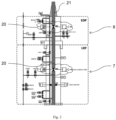
- the emergency disconnect package (EDP) 8 and the lower riser package (LRP) 7 are further illustrated in detail in figure 1 and 2 .
- both these packages 7, 8 are used under normal operating conditions. When required to do so the EDP 8 disconnects from the LRP 7 and isolates the riser 11 from the well head 2.
- the lower riser package 7 and the emergency disconnect package 8 comprises a gate valve assembly 20 with a cutting member 30 for cutting a string or similar that could be present in the workover riser system as described in the introductory part of the application.
- the figure 2 show one gate valve assembly 20 arranged in the emergency disconnect package 8 and one gate valve assembly 20 arranged in the lower riser package 7. There could however be arranged several gate valve assemblies 20 in both the emergency disconnect package 8 and the lower riser package 7, and possible also in the Christmas tree 6.
- Figure 2 further shows a flow path 21 extending through the work over system 1.
- the flow path 21 allows access to the wellhead 2 ( figure 1 ) and further to the well (not shown) when the gate valve assembly(s) 20 is open.
- Figure 3 shows a gate valve assembly 15 according to prior art.
- This gate valve assembly 15 differs from a gate valve assembly 20 according to the invention in that a gate valve member 16 is constructed differently in the two solutions.
- the remaining features are equal in the prior art gate assembly 15 and the main parts of the gate valve assembly 20 according to the invention will be described in detail with reference to this figure 3 .
- This gate valve assembly 15 comprises a valve block 22 that houses one or more components of the gate valve assembly 15.
- the valve block 22 having a flow path 21c extending through the valve block 22 with an inlet opening 21a and an outlet opening 21b in the valve block.
- the flow path 21c allows the string or similar to pass through the valve block 22 and is part of the flow path 21 extending through the subsea workover system as described in relation to figure 2 .
- the gate valve assembly 15 further comprises a gate valve member 16 that can be operated by actuating mechanism 24, 25 to move the gate valve member 16 between a first position where the flow path 21c is open and a second position where the flow path 21c is closed.
- actuating mechanism 24, 25 to move the gate valve member 16 between a first position where the flow path 21c is open and a second position where the flow path 21c is closed.
- Possible actuators to move the gate valve member could for instance be a spring actuator 25 and a hydraulic actuator 24 that are mechanically connected to the valve block 22 as illustrated in the figure 3 .
- the actuators 24, 25 may work together in the movement of the gate valve member 16.
- the gate valve assembly may be connected to the actuators through connection members 28, 29.
- the gate valve assembly 15 further comprises a shaft 26 guided and sealed within a first connection member 28 connected to the hydraulic actuator 24.
- the shaft 26 is further connected in one end to the hydraulic actuator and in the other end connected to the gate valve member 16.
- the gate valve assembly 15 further comprises a push rod 27 guided and sealed within a second connection member 29.
- the push rod 27 is arranged between the spring actuator 25 and the gate valve member 16.
- the gate valve member 16 further comprising a first portion 31 having a cutting member 30.
- the first portion 31 having an opening or through hole 32 adapted to mate with the flow path 21c when the gate valve member 16 is arranged in the first position in the gate valve assembly 15.
- the gate valve assembly 15 further having a set of annular valve seats 33, 34 arranged at each side of the gate valve member 16.
- the seats 33, 34 are further mounted coaxially with the flow path 21c with an inner diameter 33a, 34a substantial equal to the diameter of the flow path 21c.
- An end portion of each of the seats 33, 34 is facing the gate valve member 16.
- the seats 33, 34 having a circular shape around the flow path 21c.
- gate valve assembly 15 such as other actuators and positions of the actuators, other ways for moving the gate valve member 16 or different cutting members 30 may be possible embodiments of the invention.
- the gate valve member 16 according to prior art has further a second portion 17 that is planar through the whole surface.
- the seats 33, 34 bear against the second portion and seal the gate, when the gate valve is in the in the second, closed position.
- Figure 4 shows the gate valve assembly 20 with a gate valve member 40 according to an embodiment of the present invention.
- the gate valve member 40 has a first portion 31 as described in relation to figure 3 .
- the gate valve member 40 comprises further a second portion 41.
- the second portion has a recessed part 42.
- This part 42 is being positioned at the side or surface of the gate valve member 40 that is exposed to possible falling objects or similar.
- the recessed part 42 is further positioned so that when the gate valve member 40 is in the second, closed position, the recessed part 42 is arranged within the flow path 21c.
- the seat 33 is completely surrounding the recessed part 42. This results in that the seats 33 and the gate valve member 40 creates a planar sealing surface 44 as shown in the figure 4 .
- the planar sealing surface 44 is formed by the shape of the seat facing the gate valve member 40.
- the sealing surface 44 is thus formed as circular ring outside of the recessed part 42.
- the inner boundary of the sealing surface 44 may not be at the inside of the recessed part 42.
- the sealing surface 44 allows the gate valve member to be positioned within a range as long as each seal is completely contained in the planar sealing surface 44 when the gate valve member 40 is positioned in the second position.
- the inner diameter of the seal facing the flow path 21c must thus be larger or equal to the recessed part 42.
- the sealing surface 44 between the gate valve member 40 and the seats 33, 34 are clearly defined on the flat top and bottom planar surface of the gate valve member 40. The sealing surface 44 will thus be situated outside of the recessed area 42.
- the recessed part 42 comprises a conical shape 46 towards the circular end portion, as shown in the figure 5 . This will make a smoother transmission from the recessed part 42 to the upper surface of the valve block member 40. If for instance a tool is positioned in the recessed part 42 when the gate valve is in the second, closed position, this would not get stuck if the gate valve member 40 is moved to the first open position.
- recessed part 42 includes both the conical shape 46 and a recessed shape 47 in the center of the recessed part 42.
- the second portion 41 may optionally have a further recessed part 43 arranged at the opposite side of the gate valve member 40.
- the second recessed part 43 has the same position with the flow path 21c as the recessed part 42 and has the same shape as the first recessed part 42.
- the criteria as described above for the first recessed part 42 is also applicable for the second recessed part 43.
- a planar sealing surface 45 is then formed by the shape of the seat 34 facing the gate valve member 40 at the bottom side of the gate valve member.
- This embodiment with the two recessed parts 42, 43 is shown in figure 4 .
- the gate valve member 40 is shown isolated in figure 5 .
- the figure shows first portion 31 with through hole 32 and cutting member 30.
- the cutting member 30 is arranged on the outer periphery of the first portion 31 surrounding the through hole 32 facing the second part 41. This makes the cutting most efficient when moving the gate valve member 40 to the second, closed position.
- the figure further shows the second portion 41 with the recessed part 42, illustrated as a circular line in the figure.
- the outer coating such as tungsten carbide is removed so that the recessed part 42, 43 has a surface of the core material of the gate valve member 40.
- This core material could for instance be different grades of steel.
Landscapes
- Engineering & Computer Science (AREA)
- Geology (AREA)
- Life Sciences & Earth Sciences (AREA)
- Mining & Mineral Resources (AREA)
- Environmental & Geological Engineering (AREA)
- Fluid Mechanics (AREA)
- Physics & Mathematics (AREA)
- General Life Sciences & Earth Sciences (AREA)
- Geochemistry & Mineralogy (AREA)
- General Engineering & Computer Science (AREA)
- Mechanical Engineering (AREA)
- Sliding Valves (AREA)
- Multiple-Way Valves (AREA)
Description
- The invention relates to a gate valve for use in connection with oil and gas production, especially for use in relation to a subsea workover system according to the ingress of the
subsequent claim 1. - An open water Workover System consists of a Lower riser package (LRP) and an emergency disconnect package (EDP), a Workover Riser and a Surface Flow Tree. During preparations for a wireline operation through the Workover System, a tool string is lowered into the riser at Rig level.
- A gate valve is in such system used as a barrier function valve in the Workover stack in either LRP or EDP.
- During oil and gas production, and in particular during work-over and testing wells, wire line operations are common. Various tools and instruments are supported and manipulated by a string, for instance cables, lines, wires, coils or piano wires. These strings are passing through the wellhead when performing operation in the well by the tools or instruments.
- Ideally, the string is removed from the workover riser system before the gate valve is closing. However, during emergency situations, there is no time to remove the string before the valve is closing, resulting in that the valve is closing when the string is present in the valve. The valve must then cut the string in order to close and maintain the seal after the valve is seated. A gate valve provided with cutting mechanism is known from the previous applications by the same applicant
NO20131528 WO2012/093312 . The gate valve according to the invention may contain any of the features present in these applications. - During the preparations part of the wire line operation, the barrier valves of the LRP and EDP are normally closed. If parts of the tool string or the whole tool string should be accidentally dropped during this initial part of the wireline operation, the parts could fall hundreds of meters down the Workover Riser before they hit the closed gate of any of the Subsea barrier valves. Such a hit would most likely damage the surface of the gate and hence ruin the sealing capability of the valve when opened and closed again. This would likely lead to an aborted operation and retrieval of the Workover System to surface for inspection and potential repair.
- This may also occur in the Christmas tree when attached to the workover system, a gate valve according to the invention may therefore also be arranged in the Christmas tree.
- The surface of the gate valve is equipped with a coating for wear resistance and sealability. This coating is typically made of a hard material such as tungsten carbide or similar hard substance which makes the gate able to slide smooth and easily on the surface of the seats between the open position and the closed position. The material is very hard but is not able to withstand object that hits the surface, ie to withstand concentrated load.
- It is however necessary that the gate valve member have this coating to provide an easy opening and closing of the gate and to avoid wear.
- If an object is falling inside the system and hit the surface of the gate valve member when the gate valve is closed, this would result in a cracking of the coating in this area and possible damage of the base material. The result of this is that the area becomes a rough surface not suitable for sliding the gate valve member across the seat sealing surface inside the valve housing. Consequently, the gate valve member must be replaced or repaired, which would be very costly since the gate valve is positioned in the LRP or EDP near the wellhead of the work over system, which could be in the deep-water area of the sea. The entire stack (LRP or EDP) must be removed and brought the sea-surface for replacement or maintenance.
-
GB2464604 - The publication
WO 2018/096312 A1 , describes a way of protecting the gate from dropped objects by making a recess in the gate surface. However, the publication describes in detail in the application and in the first claim that the seats (upper and lower) shall both seal inside the conical surface forming the recess when the valve is in the closed position. - The solution in this publication thus requires that the positioning of the gate with respect to the seals must be very accurate in order for the gate valve to maintain its sealing properties.
- The invention is further initiated to meet new and stricter requirements from applicable industry standards and customer specifications with respect to documented dropped object performance.
- The present invention thus provides a robust and reliable product that would avoid or reduce unnecessary maintenance of the system and eliminate the above disadvantage of the prior gate valves.
- The invention relates to a gate valve assembly for use in a subsea workover system comprising a valve block having a flow path;
- valve seats located within the valve block around a periphery of the flow path, a gate valve member which is moveable across the flow path between a first position in which the flow path is open and a second position in which the flow path is closed;
- said gate valve member comprising a first portion surrounding an opening adapted to mate with the flow path when the gate valve member is in the first position, said first portion is provided with a cutting member arranged on the periphery of the first portion towards the opening. The gate valve member further comprises a second portion having at least one recessed part, said at least one recessed part is substantially circular positioned at the side or surface exposed to a possible falling object, said at least one recessed part being
- further located inside the flow path when the gate valve member is in the second position so that the gate valve member and the seats forms a sealing area on a planar surface of the gate valve member.
- Preferably, the sealing area is arranged outside of the at least one recessed part.
- Preferably, the diameter of the at least one recessed part is equal or less than the inner diameter of the seats.
- Preferably, the surface of the at least one recessed part is the same as the core material of the gate valve member.
- Preferably, a first recessed part is arranged on the surface facing a sea surface of the gate valve member, when arranged in the subsea workover system.
- Preferably, the gate valve member comprising a second recessed part, said second recessed part being arranged on the opposite side of the gate valve member than the first recessed part, said second recessed part is equal to the first recessed part.
- The invention further relates to an emergency disconnect package for use in a subsea workover system comprising a gate valve according to the invention.
- The invention also relates to a lower riser package for use in a subsea workover system comprising a gate valve according to the invention.
- The invention also related to a Christmas tree for use in a subsea workover system comprising a gate valve according to the invention.
- The gate valves in the main bore of the LRP stack will include a gate with tungsten carbide coating on the top and bottom sealing surface. This surface is polished to mirror finish to be able to seal for gas. In addition to the high surface finish, the tungsten carbide coating is very hard and hence also very brittle when exposed to impact point loads. The surface of the closed gate in the center of the valve bore is therefore not very suited to accept any hard, mechanical impact loads from dropped objects.
- The invention will eliminate the damaging effect of a dropped object by removing the coating in a circular area inside the valve bore diameter and hence remove the negative effect of tungsten carbide or similar material being cracked during a mechanical impact. Further, the same surface will be slightly recessed into the gate so that any mechanical damage and notches formed in the surface as a result from the mechanical impact will not get in contact with the valve seats when the valve is operated from a second closed position to a first, open position after an impact incident. Hence the new gate design will tolerate dropped objects as the sealing surface between gate and seat on the top of the gate will be fully protected outside the valve bore and outside the recessed area. Any damage to the gate surface will not affect the seats when valve is opened and closed again.
-
-
Figure 1 shows an overview of a typical work over system where the gate valve assembly according to the invention is used,
Thefigure 1 further shows a perspective view of an emergency disconnection package (EDP), a lower riser package (LRP) and a Christmas tree where the gate valve assembly according to the invention could be installed, -
Figure 2 shows a schematic view of the EDP and LRP with the gate valve assembly according to the invention, -
Figure 3 shows a gate valve assembly with cutting performance according to prior art in a closed position, -
Figure 4 shows a detail view of an embodiment of the gate valve assembly according to the present invention. -
Figure 5 shows a detail view of an embodiment of the gate valve member according to the present invention. - The term "subsea workover system" must be interpreted to also include the Christmas tree when the workover system is connected to this Christmas tree at the seabed. The gate valve according to the invention is also suitable for use in such a Christmas tree in a similar way as described for the gate valve of the EDP and LRP.
- The term "string" is to be interpreted in the broadest possible way. The string could for instance be one or more of a wire, a cable, a coiled tubing, a pipeline, a slickline etc.
-
Figure 1 shows an overview of a typical subsea work over system in which a gate valve assembly according to the invention is used. - The figure shows typical main components in a subsea work over
system 1 from awellhead 2 on theseabed 3 to arig deck 4 situated at thesea surface 5. Listed from the wellhead the subsea work over system may comprise the following elements:
AChristmas tree 6 connected to thewellhead 2, alower riser package 7 and an emergency disconnectedpackage 8 arranged above theChristmas tree 6, ariser 11 with possible addition of joints, such asstress joint 9, safety joint 10, landing joint 12 as shown in the figure. In addition to this, theriser 11 is tensioned by atension arrangement 13 situated between therig deck 4 and theriser 11. The subsea work oversystem 1 as such is well known for a skilled person in the art. - The emergency disconnect package (EDP) 8 and the lower riser package (LRP) 7 are further illustrated in detail in
figure 1 and2 . - Both these
packages EDP 8 disconnects from theLRP 7 and isolates theriser 11 from thewell head 2. - As shown in
Figure 2 thelower riser package 7 and theemergency disconnect package 8 comprises agate valve assembly 20 with a cuttingmember 30 for cutting a string or similar that could be present in the workover riser system as described in the introductory part of the application. - The
figure 2 show onegate valve assembly 20 arranged in theemergency disconnect package 8 and onegate valve assembly 20 arranged in thelower riser package 7. There could however be arranged severalgate valve assemblies 20 in both theemergency disconnect package 8 and thelower riser package 7, and possible also in theChristmas tree 6. -
Figure 2 further shows aflow path 21 extending through the work oversystem 1. Theflow path 21 allows access to the wellhead 2 (figure 1 ) and further to the well (not shown) when the gate valve assembly(s) 20 is open. -
Figure 3 shows agate valve assembly 15 according to prior art. - This
gate valve assembly 15 according to prior art differs from agate valve assembly 20 according to the invention in that agate valve member 16 is constructed differently in the two solutions. The remaining features are equal in the priorart gate assembly 15 and the main parts of thegate valve assembly 20 according to the invention will be described in detail with reference to thisfigure 3 . - This
gate valve assembly 15 comprises avalve block 22 that houses one or more components of thegate valve assembly 15. Thevalve block 22 having aflow path 21c extending through thevalve block 22 with aninlet opening 21a and anoutlet opening 21b in the valve block. Theflow path 21c allows the string or similar to pass through thevalve block 22 and is part of theflow path 21 extending through the subsea workover system as described in relation tofigure 2 . - The
gate valve assembly 15 further comprises agate valve member 16 that can be operated by actuatingmechanism gate valve member 16 between a first position where theflow path 21c is open and a second position where theflow path 21c is closed. Possible actuators to move the gate valve member could for instance be aspring actuator 25 and ahydraulic actuator 24 that are mechanically connected to thevalve block 22 as illustrated in thefigure 3 . Theactuators gate valve member 16. - The gate valve assembly may be connected to the actuators through
connection members - The
gate valve assembly 15 further comprises ashaft 26 guided and sealed within afirst connection member 28 connected to thehydraulic actuator 24. - The
shaft 26 is further connected in one end to the hydraulic actuator and in the other end connected to thegate valve member 16. - The
gate valve assembly 15 further comprises apush rod 27 guided and sealed within asecond connection member 29. Thepush rod 27 is arranged between thespring actuator 25 and thegate valve member 16. - The
gate valve member 16 further comprising afirst portion 31 having a cuttingmember 30. Thefirst portion 31 having an opening or throughhole 32 adapted to mate with theflow path 21c when thegate valve member 16 is arranged in the first position in thegate valve assembly 15. - The
gate valve assembly 15 further having a set of annular valve seats 33, 34 arranged at each side of thegate valve member 16. Theseats flow path 21c with aninner diameter flow path 21c. An end portion of each of theseats gate valve member 16. Theseats flow path 21c. - Other arrangements of the
gate valve assembly 15 such as other actuators and positions of the actuators, other ways for moving thegate valve member 16 ordifferent cutting members 30 may be possible embodiments of the invention. - The
gate valve member 16 according to prior art has further asecond portion 17 that is planar through the whole surface. Theseats -
Figure 4 shows thegate valve assembly 20 with agate valve member 40 according to an embodiment of the present invention. - The
gate valve member 40 has afirst portion 31 as described in relation tofigure 3 . - The
gate valve member 40 according to invention comprises further asecond portion 41. The second portion has a recessedpart 42. Thispart 42 is being positioned at the side or surface of thegate valve member 40 that is exposed to possible falling objects or similar. The recessedpart 42 is further positioned so that when thegate valve member 40 is in the second, closed position, the recessedpart 42 is arranged within theflow path 21c. Theseat 33 is completely surrounding the recessedpart 42. This results in that theseats 33 and thegate valve member 40 creates aplanar sealing surface 44 as shown in thefigure 4 . Theplanar sealing surface 44 is formed by the shape of the seat facing thegate valve member 40. The sealingsurface 44 is thus formed as circular ring outside of the recessedpart 42. The inner boundary of the sealingsurface 44 may not be at the inside of the recessedpart 42. - The consequence of this is that the positioning of the
gate valve member 40 after movement do not have to be accurate. The sealingsurface 44 allows the gate valve member to be positioned within a range as long as each seal is completely contained in theplanar sealing surface 44 when thegate valve member 40 is positioned in the second position. The inner diameter of the seal facing theflow path 21c must thus be larger or equal to the recessedpart 42. The sealingsurface 44 between thegate valve member 40 and theseats gate valve member 40. The sealingsurface 44 will thus be situated outside of the recessedarea 42. - The recessed
part 42 comprises aconical shape 46 towards the circular end portion, as shown in thefigure 5 . This will make a smoother transmission from the recessedpart 42 to the upper surface of thevalve block member 40. If for instance a tool is positioned in the recessedpart 42 when the gate valve is in the second, closed position, this would not get stuck if thegate valve member 40 is moved to the first open position. - The term recessed
part 42 includes both theconical shape 46 and a recessedshape 47 in the center of the recessedpart 42. - The
second portion 41 may optionally have a further recessedpart 43 arranged at the opposite side of thegate valve member 40. The second recessedpart 43 has the same position with theflow path 21c as the recessedpart 42 and has the same shape as the first recessedpart 42. The criteria as described above for the first recessedpart 42 is also applicable for the second recessedpart 43. - A
planar sealing surface 45 is then formed by the shape of theseat 34 facing thegate valve member 40 at the bottom side of the gate valve member. - This embodiment with the two recessed
parts figure 4 . - This makes it possible to use both sides of the
gate valve member 40. This will also reduce the risk of inserting thegate valve member 40 wrongly in thegate valve assembly 20. - The
gate valve member 40 is shown isolated infigure 5 . The figure showsfirst portion 31 with throughhole 32 and cuttingmember 30. The cuttingmember 30 is arranged on the outer periphery of thefirst portion 31 surrounding the throughhole 32 facing thesecond part 41. This makes the cutting most efficient when moving thegate valve member 40 to the second, closed position. - The figure further shows the
second portion 41 with the recessedpart 42, illustrated as a circular line in the figure. In the recessedpart part gate valve member 40. This core material could for instance be different grades of steel. - The present invention has been described with reference to a preferred embodiment and some drawings for the sake of understanding only and it should be clear to persons skilled in the art that the present invention includes all legitimate modifications within the ambit of what has been described hereinbefore and claimed in the appended claims.
Claims (6)
- A gate valve assembly (20) for use in a subsea workover system comprising- a valve block (22) having a flow path (21c);- valve seats (33, 34) located within the valve block (22) around a periphery of the flow path (21c),- a gate valve member (40) which is moveable across the flow path (21c) between a first position in which the flow path (21c) is open and a second position in which the flow path (21c) is closed;- said gate valve member (40) comprising a first portion (31) surrounding an opening (32) adapted to mate with the flow path (21c) when the gate valve member (40) is in the first position, said first portion (31) is provided with a cutting member (30) arranged on the periphery of the first portion (31) towards the opening (32), wherein,the gate valve member (40) further comprises a second portion (41) having at least one recessed part (42, 43), said recessed part (42, 43)) being positioned such that when the gate valve member (40) is in the second position, the recessed part (42) is within the flow path (21c) and at the side or surface of the gate valve member (40) that is exposed to possible falling objects and the gate valve member (40) characterised in that,
the seats (33, 34) form a sealing area (44, 45) arranged on a planar surface of the gate valve member (40), wherein the sealing area (44, 45) is arranged outside of the at least one recessed part (42, 43), wherein the diameter of the at least one recessed part (42, 43) is equal or less than the inner diameter of the seats (33a, 34a). - The gate valve according to claim 1, wherein the surface material of the at least one recessed part (42, 43) is the same as the core material of the gate valve member (40).
- The gate valve according to any one of the preceding claims, wherein the gate valve member (40) comprising a second recessed part (43), said second recessed part (43) being arranged on the opposite side of the gate valve member (40) than the first recessed part (42), said second recessed part (43) is equal to the first recessed part (42).
- An emergency disconnect package for use in a subsea workover system comprising a gate valve according to any one of claims 1-3.
- A lower riser package for use in a subsea workover system comprising a gate valve according to any one of claims 1-3.
- A Christmas tree for use in a subsea workover system comprising a gate valve according to any one of claims 1-3.
Applications Claiming Priority (2)
| Application Number | Priority Date | Filing Date | Title |
|---|---|---|---|
| NO20181288A NO345339B1 (en) | 2018-10-05 | 2018-10-05 | Gate valve assembly for a subsea workover system |
| PCT/EP2019/076873 WO2020070266A1 (en) | 2018-10-05 | 2019-10-04 | Gate valve assembly for a subsea workover system |
Publications (2)
| Publication Number | Publication Date |
|---|---|
| EP3861191A1 EP3861191A1 (en) | 2021-08-11 |
| EP3861191B1 true EP3861191B1 (en) | 2023-11-29 |
Family
ID=68159119
Family Applications (1)
| Application Number | Title | Priority Date | Filing Date |
|---|---|---|---|
| EP19783291.8A Active EP3861191B1 (en) | 2018-10-05 | 2019-10-04 | Gate valve assembly for a subsea workover system |
Country Status (4)
| Country | Link |
|---|---|
| US (1) | US11549331B2 (en) |
| EP (1) | EP3861191B1 (en) |
| NO (1) | NO345339B1 (en) |
| WO (1) | WO2020070266A1 (en) |
Families Citing this family (2)
| Publication number | Priority date | Publication date | Assignee | Title |
|---|---|---|---|---|
| TW202517916A (en) | 2023-06-23 | 2025-05-01 | 荷蘭商Asm Ip私人控股有限公司 | Gate valve interface surface, gate valve, and substrate processing system |
| US12359540B2 (en) * | 2023-11-20 | 2025-07-15 | Fmc Technologies, Inc. | Overpressure valve system for a subsea manifold |
Family Cites Families (10)
| Publication number | Priority date | Publication date | Assignee | Title |
|---|---|---|---|---|
| US2386841A (en) * | 1941-10-07 | 1945-10-16 | Beaumont Iron Works Company | Well completion apparatus |
| US5370362A (en) | 1993-10-15 | 1994-12-06 | Abb Vetco Gray Inc. | Gate valve |
| US8714263B2 (en) * | 2001-03-08 | 2014-05-06 | Worldwide Oilfield Machine, Inc. | Lightweight and compact subsea intervention package and method |
| US8070131B2 (en) * | 2008-10-27 | 2011-12-06 | Vetco Gray Inc. | Recessed cutting edge for wire cutting gate valves |
| RU2576042C2 (en) | 2011-01-04 | 2016-02-27 | Акер Сабси АС | Block valve unit and station |
| WO2014144792A2 (en) * | 2013-03-15 | 2014-09-18 | Fmc Technologies, Inc. | Gate valve assembly comprising a shear gate |
| NO341880B1 (en) | 2013-11-18 | 2018-02-12 | Aker Solutions As | Symmetrical cutting valve seats |
| NO342043B1 (en) * | 2015-12-08 | 2018-03-19 | Aker Solutions As | Workover Safety System |
| GB201619693D0 (en) | 2016-11-22 | 2017-01-04 | Interventek Subsea Eng Ltd | Gate valve |
| NO344391B1 (en) * | 2017-04-12 | 2019-11-25 | Aker Solutions As | A wellhead arrangement and installation method |
-
2018
- 2018-10-05 NO NO20181288A patent/NO345339B1/en unknown
-
2019
- 2019-10-04 US US17/280,445 patent/US11549331B2/en active Active
- 2019-10-04 EP EP19783291.8A patent/EP3861191B1/en active Active
- 2019-10-04 WO PCT/EP2019/076873 patent/WO2020070266A1/en not_active Ceased
Also Published As
| Publication number | Publication date |
|---|---|
| NO20181288A1 (en) | 2020-04-06 |
| US20220003073A1 (en) | 2022-01-06 |
| US11549331B2 (en) | 2023-01-10 |
| NO345339B1 (en) | 2020-12-14 |
| EP3861191A1 (en) | 2021-08-11 |
| WO2020070266A1 (en) | 2020-04-09 |
Similar Documents
| Publication | Publication Date | Title |
|---|---|---|
| US10233716B2 (en) | Blowout preventer including blind seal assembly | |
| US6601650B2 (en) | Method and apparatus for replacing BOP with gate valve | |
| CA1118339A (en) | Diverter tool | |
| AU2008228044B2 (en) | Connector | |
| US10533667B2 (en) | Shearing gate valve system | |
| US10450834B2 (en) | Ball valve | |
| US20100236786A1 (en) | System and method for performing intervention operations with a subsea y-tool | |
| AU2011354087B2 (en) | Gate valve assembly | |
| NO20110378A1 (en) | The annulus isolation valve | |
| US11549331B2 (en) | Gate valve assembly for a subsea workover system | |
| US11053766B2 (en) | Wireline blind shear ram | |
| US6615921B2 (en) | Apparatus and method for remote adjustment of drill string centering to prevent damage to wellhead | |
| US12535141B2 (en) | Reduced stroke gate valve | |
| US11248440B2 (en) | Valve seat and valve | |
| US9909393B2 (en) | Tubing hanger with shuttle rod valve | |
| US10550660B2 (en) | Blind shear ram | |
| EP3680448B1 (en) | Improved hang off ram preventer | |
| US20140290949A1 (en) | Apparatus, Module, Device and Method for Shearing Objects | |
| US10683727B1 (en) | Valve for mineral extraction systems | |
| US20170101842A1 (en) | Completion System with External Gate Valve | |
| WO2014011639A1 (en) | Variable inner diameter shear and seal ball valve | |
| WO2024097042A1 (en) | Interlocking rams for a blowout preventer | |
| WO2022094569A1 (en) | Bi-directional ram for a blowout preventer | |
| AU721848B2 (en) | Well completion lubricator valve |
Legal Events
| Date | Code | Title | Description |
|---|---|---|---|
| STAA | Information on the status of an ep patent application or granted ep patent |
Free format text: STATUS: UNKNOWN |
|
| STAA | Information on the status of an ep patent application or granted ep patent |
Free format text: STATUS: THE INTERNATIONAL PUBLICATION HAS BEEN MADE |
|
| PUAI | Public reference made under article 153(3) epc to a published international application that has entered the european phase |
Free format text: ORIGINAL CODE: 0009012 |
|
| STAA | Information on the status of an ep patent application or granted ep patent |
Free format text: STATUS: REQUEST FOR EXAMINATION WAS MADE |
|
| 17P | Request for examination filed |
Effective date: 20210427 |
|
| AK | Designated contracting states |
Kind code of ref document: A1 Designated state(s): AL AT BE BG CH CY CZ DE DK EE ES FI FR GB GR HR HU IE IS IT LI LT LU LV MC MK MT NL NO PL PT RO RS SE SI SK SM TR |
|
| DAV | Request for validation of the european patent (deleted) | ||
| DAX | Request for extension of the european patent (deleted) | ||
| STAA | Information on the status of an ep patent application or granted ep patent |
Free format text: STATUS: EXAMINATION IS IN PROGRESS |
|
| 17Q | First examination report despatched |
Effective date: 20230228 |
|
| GRAP | Despatch of communication of intention to grant a patent |
Free format text: ORIGINAL CODE: EPIDOSNIGR1 |
|
| STAA | Information on the status of an ep patent application or granted ep patent |
Free format text: STATUS: GRANT OF PATENT IS INTENDED |
|
| INTG | Intention to grant announced |
Effective date: 20230517 |
|
| GRAS | Grant fee paid |
Free format text: ORIGINAL CODE: EPIDOSNIGR3 |
|
| GRAA | (expected) grant |
Free format text: ORIGINAL CODE: 0009210 |
|
| STAA | Information on the status of an ep patent application or granted ep patent |
Free format text: STATUS: THE PATENT HAS BEEN GRANTED |
|
| AK | Designated contracting states |
Kind code of ref document: B1 Designated state(s): AL AT BE BG CH CY CZ DE DK EE ES FI FR GB GR HR HU IE IS IT LI LT LU LV MC MK MT NL NO PL PT RO RS SE SI SK SM TR |
|
| REG | Reference to a national code |
Ref country code: GB Ref legal event code: FG4D |
|
| REG | Reference to a national code |
Ref country code: CH Ref legal event code: EP |
|
| REG | Reference to a national code |
Ref country code: DE Ref legal event code: R096 Ref document number: 602019042444 Country of ref document: DE |
|
| REG | Reference to a national code |
Ref country code: IE Ref legal event code: FG4D |
|
| REG | Reference to a national code |
Ref country code: NO Ref legal event code: T2 Effective date: 20231129 |
|
| REG | Reference to a national code |
Ref country code: LT Ref legal event code: MG9D |
|
| REG | Reference to a national code |
Ref country code: NL Ref legal event code: MP Effective date: 20231129 |
|
| PG25 | Lapsed in a contracting state [announced via postgrant information from national office to epo] |
Ref country code: GR Free format text: LAPSE BECAUSE OF FAILURE TO SUBMIT A TRANSLATION OF THE DESCRIPTION OR TO PAY THE FEE WITHIN THE PRESCRIBED TIME-LIMIT Effective date: 20240301 |
|
| PG25 | Lapsed in a contracting state [announced via postgrant information from national office to epo] |
Ref country code: IS Free format text: LAPSE BECAUSE OF FAILURE TO SUBMIT A TRANSLATION OF THE DESCRIPTION OR TO PAY THE FEE WITHIN THE PRESCRIBED TIME-LIMIT Effective date: 20240329 |
|
| PG25 | Lapsed in a contracting state [announced via postgrant information from national office to epo] |
Ref country code: LT Free format text: LAPSE BECAUSE OF FAILURE TO SUBMIT A TRANSLATION OF THE DESCRIPTION OR TO PAY THE FEE WITHIN THE PRESCRIBED TIME-LIMIT Effective date: 20231129 |
|
| PG25 | Lapsed in a contracting state [announced via postgrant information from national office to epo] |
Ref country code: ES Free format text: LAPSE BECAUSE OF FAILURE TO SUBMIT A TRANSLATION OF THE DESCRIPTION OR TO PAY THE FEE WITHIN THE PRESCRIBED TIME-LIMIT Effective date: 20231129 |
|
| PG25 | Lapsed in a contracting state [announced via postgrant information from national office to epo] |
Ref country code: LT Free format text: LAPSE BECAUSE OF FAILURE TO SUBMIT A TRANSLATION OF THE DESCRIPTION OR TO PAY THE FEE WITHIN THE PRESCRIBED TIME-LIMIT Effective date: 20231129 Ref country code: IS Free format text: LAPSE BECAUSE OF FAILURE TO SUBMIT A TRANSLATION OF THE DESCRIPTION OR TO PAY THE FEE WITHIN THE PRESCRIBED TIME-LIMIT Effective date: 20240329 Ref country code: GR Free format text: LAPSE BECAUSE OF FAILURE TO SUBMIT A TRANSLATION OF THE DESCRIPTION OR TO PAY THE FEE WITHIN THE PRESCRIBED TIME-LIMIT Effective date: 20240301 Ref country code: ES Free format text: LAPSE BECAUSE OF FAILURE TO SUBMIT A TRANSLATION OF THE DESCRIPTION OR TO PAY THE FEE WITHIN THE PRESCRIBED TIME-LIMIT Effective date: 20231129 Ref country code: BG Free format text: LAPSE BECAUSE OF FAILURE TO SUBMIT A TRANSLATION OF THE DESCRIPTION OR TO PAY THE FEE WITHIN THE PRESCRIBED TIME-LIMIT Effective date: 20240229 |
|
| REG | Reference to a national code |
Ref country code: AT Ref legal event code: MK05 Ref document number: 1636292 Country of ref document: AT Kind code of ref document: T Effective date: 20231129 |
|
| PG25 | Lapsed in a contracting state [announced via postgrant information from national office to epo] |
Ref country code: NL Free format text: LAPSE BECAUSE OF FAILURE TO SUBMIT A TRANSLATION OF THE DESCRIPTION OR TO PAY THE FEE WITHIN THE PRESCRIBED TIME-LIMIT Effective date: 20231129 |
|
| PG25 | Lapsed in a contracting state [announced via postgrant information from national office to epo] |
Ref country code: SE Free format text: LAPSE BECAUSE OF FAILURE TO SUBMIT A TRANSLATION OF THE DESCRIPTION OR TO PAY THE FEE WITHIN THE PRESCRIBED TIME-LIMIT Effective date: 20231129 Ref country code: RS Free format text: LAPSE BECAUSE OF FAILURE TO SUBMIT A TRANSLATION OF THE DESCRIPTION OR TO PAY THE FEE WITHIN THE PRESCRIBED TIME-LIMIT Effective date: 20231129 Ref country code: PL Free format text: LAPSE BECAUSE OF FAILURE TO SUBMIT A TRANSLATION OF THE DESCRIPTION OR TO PAY THE FEE WITHIN THE PRESCRIBED TIME-LIMIT Effective date: 20231129 Ref country code: NL Free format text: LAPSE BECAUSE OF FAILURE TO SUBMIT A TRANSLATION OF THE DESCRIPTION OR TO PAY THE FEE WITHIN THE PRESCRIBED TIME-LIMIT Effective date: 20231129 Ref country code: LV Free format text: LAPSE BECAUSE OF FAILURE TO SUBMIT A TRANSLATION OF THE DESCRIPTION OR TO PAY THE FEE WITHIN THE PRESCRIBED TIME-LIMIT Effective date: 20231129 Ref country code: HR Free format text: LAPSE BECAUSE OF FAILURE TO SUBMIT A TRANSLATION OF THE DESCRIPTION OR TO PAY THE FEE WITHIN THE PRESCRIBED TIME-LIMIT Effective date: 20231129 |
|
| PG25 | Lapsed in a contracting state [announced via postgrant information from national office to epo] |
Ref country code: DK Free format text: LAPSE BECAUSE OF FAILURE TO SUBMIT A TRANSLATION OF THE DESCRIPTION OR TO PAY THE FEE WITHIN THE PRESCRIBED TIME-LIMIT Effective date: 20231129 |
|
| PG25 | Lapsed in a contracting state [announced via postgrant information from national office to epo] |
Ref country code: CZ Free format text: LAPSE BECAUSE OF FAILURE TO SUBMIT A TRANSLATION OF THE DESCRIPTION OR TO PAY THE FEE WITHIN THE PRESCRIBED TIME-LIMIT Effective date: 20231129 Ref country code: AT Free format text: LAPSE BECAUSE OF FAILURE TO SUBMIT A TRANSLATION OF THE DESCRIPTION OR TO PAY THE FEE WITHIN THE PRESCRIBED TIME-LIMIT Effective date: 20231129 |
|
| PG25 | Lapsed in a contracting state [announced via postgrant information from national office to epo] |
Ref country code: SK Free format text: LAPSE BECAUSE OF FAILURE TO SUBMIT A TRANSLATION OF THE DESCRIPTION OR TO PAY THE FEE WITHIN THE PRESCRIBED TIME-LIMIT Effective date: 20231129 |
|
| PG25 | Lapsed in a contracting state [announced via postgrant information from national office to epo] |
Ref country code: SM Free format text: LAPSE BECAUSE OF FAILURE TO SUBMIT A TRANSLATION OF THE DESCRIPTION OR TO PAY THE FEE WITHIN THE PRESCRIBED TIME-LIMIT Effective date: 20231129 Ref country code: SK Free format text: LAPSE BECAUSE OF FAILURE TO SUBMIT A TRANSLATION OF THE DESCRIPTION OR TO PAY THE FEE WITHIN THE PRESCRIBED TIME-LIMIT Effective date: 20231129 Ref country code: RO Free format text: LAPSE BECAUSE OF FAILURE TO SUBMIT A TRANSLATION OF THE DESCRIPTION OR TO PAY THE FEE WITHIN THE PRESCRIBED TIME-LIMIT Effective date: 20231129 Ref country code: EE Free format text: LAPSE BECAUSE OF FAILURE TO SUBMIT A TRANSLATION OF THE DESCRIPTION OR TO PAY THE FEE WITHIN THE PRESCRIBED TIME-LIMIT Effective date: 20231129 Ref country code: DK Free format text: LAPSE BECAUSE OF FAILURE TO SUBMIT A TRANSLATION OF THE DESCRIPTION OR TO PAY THE FEE WITHIN THE PRESCRIBED TIME-LIMIT Effective date: 20231129 Ref country code: CZ Free format text: LAPSE BECAUSE OF FAILURE TO SUBMIT A TRANSLATION OF THE DESCRIPTION OR TO PAY THE FEE WITHIN THE PRESCRIBED TIME-LIMIT Effective date: 20231129 Ref country code: AT Free format text: LAPSE BECAUSE OF FAILURE TO SUBMIT A TRANSLATION OF THE DESCRIPTION OR TO PAY THE FEE WITHIN THE PRESCRIBED TIME-LIMIT Effective date: 20231129 |
|
| PG25 | Lapsed in a contracting state [announced via postgrant information from national office to epo] |
Ref country code: PT Free format text: LAPSE BECAUSE OF FAILURE TO SUBMIT A TRANSLATION OF THE DESCRIPTION OR TO PAY THE FEE WITHIN THE PRESCRIBED TIME-LIMIT Effective date: 20240401 |
|
| PG25 | Lapsed in a contracting state [announced via postgrant information from national office to epo] |
Ref country code: PT Free format text: LAPSE BECAUSE OF FAILURE TO SUBMIT A TRANSLATION OF THE DESCRIPTION OR TO PAY THE FEE WITHIN THE PRESCRIBED TIME-LIMIT Effective date: 20240401 |
|
| REG | Reference to a national code |
Ref country code: DE Ref legal event code: R097 Ref document number: 602019042444 Country of ref document: DE |
|
| PLBE | No opposition filed within time limit |
Free format text: ORIGINAL CODE: 0009261 |
|
| STAA | Information on the status of an ep patent application or granted ep patent |
Free format text: STATUS: NO OPPOSITION FILED WITHIN TIME LIMIT |
|
| PG25 | Lapsed in a contracting state [announced via postgrant information from national office to epo] |
Ref country code: SI Free format text: LAPSE BECAUSE OF FAILURE TO SUBMIT A TRANSLATION OF THE DESCRIPTION OR TO PAY THE FEE WITHIN THE PRESCRIBED TIME-LIMIT Effective date: 20231129 |
|
| PG25 | Lapsed in a contracting state [announced via postgrant information from national office to epo] |
Ref country code: SI Free format text: LAPSE BECAUSE OF FAILURE TO SUBMIT A TRANSLATION OF THE DESCRIPTION OR TO PAY THE FEE WITHIN THE PRESCRIBED TIME-LIMIT Effective date: 20231129 |
|
| 26N | No opposition filed |
Effective date: 20240830 |
|
| REG | Reference to a national code |
Ref country code: DE Ref legal event code: R119 Ref document number: 602019042444 Country of ref document: DE |
|
| REG | Reference to a national code |
Ref country code: CH Ref legal event code: PL |
|
| PG25 | Lapsed in a contracting state [announced via postgrant information from national office to epo] |
Ref country code: MC Free format text: LAPSE BECAUSE OF FAILURE TO SUBMIT A TRANSLATION OF THE DESCRIPTION OR TO PAY THE FEE WITHIN THE PRESCRIBED TIME-LIMIT Effective date: 20231129 |
|
| PG25 | Lapsed in a contracting state [announced via postgrant information from national office to epo] |
Ref country code: DE Free format text: LAPSE BECAUSE OF NON-PAYMENT OF DUE FEES Effective date: 20250501 |
|
| PG25 | Lapsed in a contracting state [announced via postgrant information from national office to epo] |
Ref country code: BE Free format text: LAPSE BECAUSE OF NON-PAYMENT OF DUE FEES Effective date: 20241031 Ref country code: LU Free format text: LAPSE BECAUSE OF NON-PAYMENT OF DUE FEES Effective date: 20241004 |
|
| PG25 | Lapsed in a contracting state [announced via postgrant information from national office to epo] |
Ref country code: FR Free format text: LAPSE BECAUSE OF NON-PAYMENT OF DUE FEES Effective date: 20241031 |
|
| PG25 | Lapsed in a contracting state [announced via postgrant information from national office to epo] |
Ref country code: CH Free format text: LAPSE BECAUSE OF NON-PAYMENT OF DUE FEES Effective date: 20241031 |
|
| REG | Reference to a national code |
Ref country code: BE Ref legal event code: MM Effective date: 20241031 |
|
| PG25 | Lapsed in a contracting state [announced via postgrant information from national office to epo] |
Ref country code: FI Free format text: LAPSE BECAUSE OF FAILURE TO SUBMIT A TRANSLATION OF THE DESCRIPTION OR TO PAY THE FEE WITHIN THE PRESCRIBED TIME-LIMIT Effective date: 20231129 |
|
| PGFP | Annual fee paid to national office [announced via postgrant information from national office to epo] |
Ref country code: IT Payment date: 20250922 Year of fee payment: 7 |
|
| PGFP | Annual fee paid to national office [announced via postgrant information from national office to epo] |
Ref country code: GB Payment date: 20250821 Year of fee payment: 7 |
|
| PG25 | Lapsed in a contracting state [announced via postgrant information from national office to epo] |
Ref country code: IE Free format text: LAPSE BECAUSE OF NON-PAYMENT OF DUE FEES Effective date: 20241004 |
|
| PGFP | Annual fee paid to national office [announced via postgrant information from national office to epo] |
Ref country code: NO Payment date: 20251009 Year of fee payment: 7 |
|
| PG25 | Lapsed in a contracting state [announced via postgrant information from national office to epo] |
Ref country code: CY Free format text: LAPSE BECAUSE OF FAILURE TO SUBMIT A TRANSLATION OF THE DESCRIPTION OR TO PAY THE FEE WITHIN THE PRESCRIBED TIME-LIMIT; INVALID AB INITIO Effective date: 20191004 |
|
| PG25 | Lapsed in a contracting state [announced via postgrant information from national office to epo] |
Ref country code: HU Free format text: LAPSE BECAUSE OF FAILURE TO SUBMIT A TRANSLATION OF THE DESCRIPTION OR TO PAY THE FEE WITHIN THE PRESCRIBED TIME-LIMIT; INVALID AB INITIO Effective date: 20191004 |