EP3860692B1 - Auto injector with effective insertion system - Google Patents
Auto injector with effective insertion system Download PDFInfo
- Publication number
- EP3860692B1 EP3860692B1 EP19779522.2A EP19779522A EP3860692B1 EP 3860692 B1 EP3860692 B1 EP 3860692B1 EP 19779522 A EP19779522 A EP 19779522A EP 3860692 B1 EP3860692 B1 EP 3860692B1
- Authority
- EP
- European Patent Office
- Prior art keywords
- syringe
- cassette
- needle shield
- auto injector
- rigid needle
- Prior art date
- Legal status (The legal status is an assumption and is not a legal conclusion. Google has not performed a legal analysis and makes no representation as to the accuracy of the status listed.)
- Active
Links
Images

















Classifications
-
- A—HUMAN NECESSITIES
- A61—MEDICAL OR VETERINARY SCIENCE; HYGIENE
- A61M—DEVICES FOR INTRODUCING MEDIA INTO, OR ONTO, THE BODY; DEVICES FOR TRANSDUCING BODY MEDIA OR FOR TAKING MEDIA FROM THE BODY; DEVICES FOR PRODUCING OR ENDING SLEEP OR STUPOR
- A61M5/00—Devices for bringing media into the body in a subcutaneous, intra-vascular or intramuscular way; Accessories therefor, e.g. filling or cleaning devices, arm-rests
- A61M5/178—Syringes
- A61M5/20—Automatic syringes, e.g. with automatically actuated piston rod, with automatic needle injection, filling automatically
-
- A—HUMAN NECESSITIES
- A61—MEDICAL OR VETERINARY SCIENCE; HYGIENE
- A61M—DEVICES FOR INTRODUCING MEDIA INTO, OR ONTO, THE BODY; DEVICES FOR TRANSDUCING BODY MEDIA OR FOR TAKING MEDIA FROM THE BODY; DEVICES FOR PRODUCING OR ENDING SLEEP OR STUPOR
- A61M5/00—Devices for bringing media into the body in a subcutaneous, intra-vascular or intramuscular way; Accessories therefor, e.g. filling or cleaning devices, arm-rests
- A61M5/178—Syringes
- A61M5/20—Automatic syringes, e.g. with automatically actuated piston rod, with automatic needle injection, filling automatically
- A61M5/2053—Media being expelled from injector by pressurised fluid or vacuum
-
- A—HUMAN NECESSITIES
- A61—MEDICAL OR VETERINARY SCIENCE; HYGIENE
- A61M—DEVICES FOR INTRODUCING MEDIA INTO, OR ONTO, THE BODY; DEVICES FOR TRANSDUCING BODY MEDIA OR FOR TAKING MEDIA FROM THE BODY; DEVICES FOR PRODUCING OR ENDING SLEEP OR STUPOR
- A61M5/00—Devices for bringing media into the body in a subcutaneous, intra-vascular or intramuscular way; Accessories therefor, e.g. filling or cleaning devices, arm-rests
- A61M5/178—Syringes
- A61M5/24—Ampoule syringes, i.e. syringes with needle for use in combination with replaceable ampoules or carpules, e.g. automatic
-
- A—HUMAN NECESSITIES
- A61—MEDICAL OR VETERINARY SCIENCE; HYGIENE
- A61M—DEVICES FOR INTRODUCING MEDIA INTO, OR ONTO, THE BODY; DEVICES FOR TRANSDUCING BODY MEDIA OR FOR TAKING MEDIA FROM THE BODY; DEVICES FOR PRODUCING OR ENDING SLEEP OR STUPOR
- A61M5/00—Devices for bringing media into the body in a subcutaneous, intra-vascular or intramuscular way; Accessories therefor, e.g. filling or cleaning devices, arm-rests
- A61M5/178—Syringes
- A61M5/28—Syringe ampoules or carpules, i.e. ampoules or carpules provided with a needle
-
- A—HUMAN NECESSITIES
- A61—MEDICAL OR VETERINARY SCIENCE; HYGIENE
- A61M—DEVICES FOR INTRODUCING MEDIA INTO, OR ONTO, THE BODY; DEVICES FOR TRANSDUCING BODY MEDIA OR FOR TAKING MEDIA FROM THE BODY; DEVICES FOR PRODUCING OR ENDING SLEEP OR STUPOR
- A61M5/00—Devices for bringing media into the body in a subcutaneous, intra-vascular or intramuscular way; Accessories therefor, e.g. filling or cleaning devices, arm-rests
- A61M5/178—Syringes
- A61M5/31—Details
- A61M5/315—Pistons; Piston-rods; Guiding, blocking or restricting the movement of the rod or piston; Appliances on the rod for facilitating dosing ; Dosing mechanisms
- A61M5/31501—Means for blocking or restricting the movement of the rod or piston
- A61M5/31505—Integral with the syringe barrel, i.e. connected to the barrel so as to make up a single complete piece or unit
-
- A—HUMAN NECESSITIES
- A61—MEDICAL OR VETERINARY SCIENCE; HYGIENE
- A61M—DEVICES FOR INTRODUCING MEDIA INTO, OR ONTO, THE BODY; DEVICES FOR TRANSDUCING BODY MEDIA OR FOR TAKING MEDIA FROM THE BODY; DEVICES FOR PRODUCING OR ENDING SLEEP OR STUPOR
- A61M5/00—Devices for bringing media into the body in a subcutaneous, intra-vascular or intramuscular way; Accessories therefor, e.g. filling or cleaning devices, arm-rests
- A61M5/178—Syringes
- A61M5/31—Details
- A61M5/315—Pistons; Piston-rods; Guiding, blocking or restricting the movement of the rod or piston; Appliances on the rod for facilitating dosing ; Dosing mechanisms
- A61M5/31565—Administration mechanisms, i.e. constructional features, modes of administering a dose
- A61M5/31576—Constructional features or modes of drive mechanisms for piston rods
-
- A—HUMAN NECESSITIES
- A61—MEDICAL OR VETERINARY SCIENCE; HYGIENE
- A61M—DEVICES FOR INTRODUCING MEDIA INTO, OR ONTO, THE BODY; DEVICES FOR TRANSDUCING BODY MEDIA OR FOR TAKING MEDIA FROM THE BODY; DEVICES FOR PRODUCING OR ENDING SLEEP OR STUPOR
- A61M5/00—Devices for bringing media into the body in a subcutaneous, intra-vascular or intramuscular way; Accessories therefor, e.g. filling or cleaning devices, arm-rests
- A61M5/178—Syringes
- A61M5/31—Details
- A61M5/315—Pistons; Piston-rods; Guiding, blocking or restricting the movement of the rod or piston; Appliances on the rod for facilitating dosing ; Dosing mechanisms
- A61M5/31565—Administration mechanisms, i.e. constructional features, modes of administering a dose
- A61M5/31576—Constructional features or modes of drive mechanisms for piston rods
- A61M5/31578—Constructional features or modes of drive mechanisms for piston rods based on axial translation, i.e. components directly operatively associated and axially moved with plunger rod
-
- A—HUMAN NECESSITIES
- A61—MEDICAL OR VETERINARY SCIENCE; HYGIENE
- A61M—DEVICES FOR INTRODUCING MEDIA INTO, OR ONTO, THE BODY; DEVICES FOR TRANSDUCING BODY MEDIA OR FOR TAKING MEDIA FROM THE BODY; DEVICES FOR PRODUCING OR ENDING SLEEP OR STUPOR
- A61M5/00—Devices for bringing media into the body in a subcutaneous, intra-vascular or intramuscular way; Accessories therefor, e.g. filling or cleaning devices, arm-rests
- A61M5/178—Syringes
- A61M5/31—Details
- A61M5/315—Pistons; Piston-rods; Guiding, blocking or restricting the movement of the rod or piston; Appliances on the rod for facilitating dosing ; Dosing mechanisms
- A61M5/31565—Administration mechanisms, i.e. constructional features, modes of administering a dose
- A61M5/31576—Constructional features or modes of drive mechanisms for piston rods
- A61M5/31578—Constructional features or modes of drive mechanisms for piston rods based on axial translation, i.e. components directly operatively associated and axially moved with plunger rod
- A61M5/3158—Constructional features or modes of drive mechanisms for piston rods based on axial translation, i.e. components directly operatively associated and axially moved with plunger rod performed by axially moving actuator operated by user, e.g. an injection button
-
- A—HUMAN NECESSITIES
- A61—MEDICAL OR VETERINARY SCIENCE; HYGIENE
- A61M—DEVICES FOR INTRODUCING MEDIA INTO, OR ONTO, THE BODY; DEVICES FOR TRANSDUCING BODY MEDIA OR FOR TAKING MEDIA FROM THE BODY; DEVICES FOR PRODUCING OR ENDING SLEEP OR STUPOR
- A61M5/00—Devices for bringing media into the body in a subcutaneous, intra-vascular or intramuscular way; Accessories therefor, e.g. filling or cleaning devices, arm-rests
- A61M5/178—Syringes
- A61M5/31—Details
- A61M5/32—Needles; Details of needles pertaining to their connection with syringe or hub; Accessories for bringing the needle into, or holding the needle on, the body; Devices for protection of needles
-
- A—HUMAN NECESSITIES
- A61—MEDICAL OR VETERINARY SCIENCE; HYGIENE
- A61M—DEVICES FOR INTRODUCING MEDIA INTO, OR ONTO, THE BODY; DEVICES FOR TRANSDUCING BODY MEDIA OR FOR TAKING MEDIA FROM THE BODY; DEVICES FOR PRODUCING OR ENDING SLEEP OR STUPOR
- A61M5/00—Devices for bringing media into the body in a subcutaneous, intra-vascular or intramuscular way; Accessories therefor, e.g. filling or cleaning devices, arm-rests
- A61M5/178—Syringes
- A61M5/31—Details
- A61M5/32—Needles; Details of needles pertaining to their connection with syringe or hub; Accessories for bringing the needle into, or holding the needle on, the body; Devices for protection of needles
- A61M5/3202—Devices for protection of the needle before use, e.g. caps
-
- A—HUMAN NECESSITIES
- A61—MEDICAL OR VETERINARY SCIENCE; HYGIENE
- A61M—DEVICES FOR INTRODUCING MEDIA INTO, OR ONTO, THE BODY; DEVICES FOR TRANSDUCING BODY MEDIA OR FOR TAKING MEDIA FROM THE BODY; DEVICES FOR PRODUCING OR ENDING SLEEP OR STUPOR
- A61M5/00—Devices for bringing media into the body in a subcutaneous, intra-vascular or intramuscular way; Accessories therefor, e.g. filling or cleaning devices, arm-rests
- A61M5/178—Syringes
- A61M5/31—Details
- A61M5/32—Needles; Details of needles pertaining to their connection with syringe or hub; Accessories for bringing the needle into, or holding the needle on, the body; Devices for protection of needles
- A61M5/3202—Devices for protection of the needle before use, e.g. caps
- A61M5/3204—Needle cap remover, i.e. devices to dislodge protection cover from needle or needle hub, e.g. deshielding devices
-
- A—HUMAN NECESSITIES
- A61—MEDICAL OR VETERINARY SCIENCE; HYGIENE
- A61M—DEVICES FOR INTRODUCING MEDIA INTO, OR ONTO, THE BODY; DEVICES FOR TRANSDUCING BODY MEDIA OR FOR TAKING MEDIA FROM THE BODY; DEVICES FOR PRODUCING OR ENDING SLEEP OR STUPOR
- A61M5/00—Devices for bringing media into the body in a subcutaneous, intra-vascular or intramuscular way; Accessories therefor, e.g. filling or cleaning devices, arm-rests
- A61M5/178—Syringes
- A61M5/31—Details
- A61M5/32—Needles; Details of needles pertaining to their connection with syringe or hub; Accessories for bringing the needle into, or holding the needle on, the body; Devices for protection of needles
- A61M5/3205—Apparatus for removing or disposing of used needles or syringes, e.g. containers; Means for protection against accidental injuries from used needles
- A61M5/321—Means for protection against accidental injuries by used needles
- A61M5/3216—Caps placed transversally onto the needle, e.g. pivotally attached to the needle base
-
- A—HUMAN NECESSITIES
- A61—MEDICAL OR VETERINARY SCIENCE; HYGIENE
- A61M—DEVICES FOR INTRODUCING MEDIA INTO, OR ONTO, THE BODY; DEVICES FOR TRANSDUCING BODY MEDIA OR FOR TAKING MEDIA FROM THE BODY; DEVICES FOR PRODUCING OR ENDING SLEEP OR STUPOR
- A61M5/00—Devices for bringing media into the body in a subcutaneous, intra-vascular or intramuscular way; Accessories therefor, e.g. filling or cleaning devices, arm-rests
- A61M5/178—Syringes
- A61M5/20—Automatic syringes, e.g. with automatically actuated piston rod, with automatic needle injection, filling automatically
- A61M2005/2006—Having specific accessories
- A61M2005/2013—Having specific accessories triggering of discharging means by contact of injector with patient body
-
- A—HUMAN NECESSITIES
- A61—MEDICAL OR VETERINARY SCIENCE; HYGIENE
- A61M—DEVICES FOR INTRODUCING MEDIA INTO, OR ONTO, THE BODY; DEVICES FOR TRANSDUCING BODY MEDIA OR FOR TAKING MEDIA FROM THE BODY; DEVICES FOR PRODUCING OR ENDING SLEEP OR STUPOR
- A61M5/00—Devices for bringing media into the body in a subcutaneous, intra-vascular or intramuscular way; Accessories therefor, e.g. filling or cleaning devices, arm-rests
- A61M5/178—Syringes
- A61M5/20—Automatic syringes, e.g. with automatically actuated piston rod, with automatic needle injection, filling automatically
- A61M2005/206—With automatic needle insertion
-
- A—HUMAN NECESSITIES
- A61—MEDICAL OR VETERINARY SCIENCE; HYGIENE
- A61M—DEVICES FOR INTRODUCING MEDIA INTO, OR ONTO, THE BODY; DEVICES FOR TRANSDUCING BODY MEDIA OR FOR TAKING MEDIA FROM THE BODY; DEVICES FOR PRODUCING OR ENDING SLEEP OR STUPOR
- A61M5/00—Devices for bringing media into the body in a subcutaneous, intra-vascular or intramuscular way; Accessories therefor, e.g. filling or cleaning devices, arm-rests
- A61M5/178—Syringes
- A61M5/20—Automatic syringes, e.g. with automatically actuated piston rod, with automatic needle injection, filling automatically
- A61M2005/2073—Automatic syringes, e.g. with automatically actuated piston rod, with automatic needle injection, filling automatically preventing premature release, e.g. by making use of a safety lock
-
- A—HUMAN NECESSITIES
- A61—MEDICAL OR VETERINARY SCIENCE; HYGIENE
- A61M—DEVICES FOR INTRODUCING MEDIA INTO, OR ONTO, THE BODY; DEVICES FOR TRANSDUCING BODY MEDIA OR FOR TAKING MEDIA FROM THE BODY; DEVICES FOR PRODUCING OR ENDING SLEEP OR STUPOR
- A61M5/00—Devices for bringing media into the body in a subcutaneous, intra-vascular or intramuscular way; Accessories therefor, e.g. filling or cleaning devices, arm-rests
- A61M5/178—Syringes
- A61M5/20—Automatic syringes, e.g. with automatically actuated piston rod, with automatic needle injection, filling automatically
- A61M2005/2073—Automatic syringes, e.g. with automatically actuated piston rod, with automatic needle injection, filling automatically preventing premature release, e.g. by making use of a safety lock
- A61M2005/208—Release is possible only when device is pushed against the skin, e.g. using a trigger which is blocked or inactive when the device is not pushed against the skin
-
- A—HUMAN NECESSITIES
- A61—MEDICAL OR VETERINARY SCIENCE; HYGIENE
- A61M—DEVICES FOR INTRODUCING MEDIA INTO, OR ONTO, THE BODY; DEVICES FOR TRANSDUCING BODY MEDIA OR FOR TAKING MEDIA FROM THE BODY; DEVICES FOR PRODUCING OR ENDING SLEEP OR STUPOR
- A61M5/00—Devices for bringing media into the body in a subcutaneous, intra-vascular or intramuscular way; Accessories therefor, e.g. filling or cleaning devices, arm-rests
- A61M5/178—Syringes
- A61M5/24—Ampoule syringes, i.e. syringes with needle for use in combination with replaceable ampoules or carpules, e.g. automatic
- A61M2005/2403—Ampoule inserted into the ampoule holder
- A61M2005/2411—Ampoule inserted into the ampoule holder from the front
-
- A—HUMAN NECESSITIES
- A61—MEDICAL OR VETERINARY SCIENCE; HYGIENE
- A61M—DEVICES FOR INTRODUCING MEDIA INTO, OR ONTO, THE BODY; DEVICES FOR TRANSDUCING BODY MEDIA OR FOR TAKING MEDIA FROM THE BODY; DEVICES FOR PRODUCING OR ENDING SLEEP OR STUPOR
- A61M5/00—Devices for bringing media into the body in a subcutaneous, intra-vascular or intramuscular way; Accessories therefor, e.g. filling or cleaning devices, arm-rests
- A61M5/178—Syringes
- A61M5/24—Ampoule syringes, i.e. syringes with needle for use in combination with replaceable ampoules or carpules, e.g. automatic
- A61M2005/2418—Ampoule syringes, i.e. syringes with needle for use in combination with replaceable ampoules or carpules, e.g. automatic comprising means for damping shocks on ampoule
-
- A—HUMAN NECESSITIES
- A61—MEDICAL OR VETERINARY SCIENCE; HYGIENE
- A61M—DEVICES FOR INTRODUCING MEDIA INTO, OR ONTO, THE BODY; DEVICES FOR TRANSDUCING BODY MEDIA OR FOR TAKING MEDIA FROM THE BODY; DEVICES FOR PRODUCING OR ENDING SLEEP OR STUPOR
- A61M5/00—Devices for bringing media into the body in a subcutaneous, intra-vascular or intramuscular way; Accessories therefor, e.g. filling or cleaning devices, arm-rests
- A61M5/178—Syringes
- A61M5/24—Ampoule syringes, i.e. syringes with needle for use in combination with replaceable ampoules or carpules, e.g. automatic
- A61M2005/2433—Ampoule fixed to ampoule holder
-
- A—HUMAN NECESSITIES
- A61—MEDICAL OR VETERINARY SCIENCE; HYGIENE
- A61M—DEVICES FOR INTRODUCING MEDIA INTO, OR ONTO, THE BODY; DEVICES FOR TRANSDUCING BODY MEDIA OR FOR TAKING MEDIA FROM THE BODY; DEVICES FOR PRODUCING OR ENDING SLEEP OR STUPOR
- A61M5/00—Devices for bringing media into the body in a subcutaneous, intra-vascular or intramuscular way; Accessories therefor, e.g. filling or cleaning devices, arm-rests
- A61M5/178—Syringes
- A61M5/24—Ampoule syringes, i.e. syringes with needle for use in combination with replaceable ampoules or carpules, e.g. automatic
- A61M2005/2485—Ampoule holder connected to rest of syringe
- A61M2005/2492—Ampoule holder connected to rest of syringe via snap connection
-
- A—HUMAN NECESSITIES
- A61—MEDICAL OR VETERINARY SCIENCE; HYGIENE
- A61M—DEVICES FOR INTRODUCING MEDIA INTO, OR ONTO, THE BODY; DEVICES FOR TRANSDUCING BODY MEDIA OR FOR TAKING MEDIA FROM THE BODY; DEVICES FOR PRODUCING OR ENDING SLEEP OR STUPOR
- A61M5/00—Devices for bringing media into the body in a subcutaneous, intra-vascular or intramuscular way; Accessories therefor, e.g. filling or cleaning devices, arm-rests
- A61M5/178—Syringes
- A61M5/31—Details
- A61M5/315—Pistons; Piston-rods; Guiding, blocking or restricting the movement of the rod or piston; Appliances on the rod for facilitating dosing ; Dosing mechanisms
- A61M5/31565—Administration mechanisms, i.e. constructional features, modes of administering a dose
- A61M5/31576—Constructional features or modes of drive mechanisms for piston rods
- A61M2005/31588—Constructional features or modes of drive mechanisms for piston rods electrically driven
-
- A—HUMAN NECESSITIES
- A61—MEDICAL OR VETERINARY SCIENCE; HYGIENE
- A61M—DEVICES FOR INTRODUCING MEDIA INTO, OR ONTO, THE BODY; DEVICES FOR TRANSDUCING BODY MEDIA OR FOR TAKING MEDIA FROM THE BODY; DEVICES FOR PRODUCING OR ENDING SLEEP OR STUPOR
- A61M2205/00—General characteristics of the apparatus
- A61M2205/12—General characteristics of the apparatus with interchangeable cassettes forming partially or totally the fluid circuit
-
- A—HUMAN NECESSITIES
- A61—MEDICAL OR VETERINARY SCIENCE; HYGIENE
- A61M—DEVICES FOR INTRODUCING MEDIA INTO, OR ONTO, THE BODY; DEVICES FOR TRANSDUCING BODY MEDIA OR FOR TAKING MEDIA FROM THE BODY; DEVICES FOR PRODUCING OR ENDING SLEEP OR STUPOR
- A61M2205/00—General characteristics of the apparatus
- A61M2205/12—General characteristics of the apparatus with interchangeable cassettes forming partially or totally the fluid circuit
- A61M2205/121—General characteristics of the apparatus with interchangeable cassettes forming partially or totally the fluid circuit interface between cassette and base
-
- A—HUMAN NECESSITIES
- A61—MEDICAL OR VETERINARY SCIENCE; HYGIENE
- A61M—DEVICES FOR INTRODUCING MEDIA INTO, OR ONTO, THE BODY; DEVICES FOR TRANSDUCING BODY MEDIA OR FOR TAKING MEDIA FROM THE BODY; DEVICES FOR PRODUCING OR ENDING SLEEP OR STUPOR
- A61M2205/00—General characteristics of the apparatus
- A61M2205/12—General characteristics of the apparatus with interchangeable cassettes forming partially or totally the fluid circuit
- A61M2205/123—General characteristics of the apparatus with interchangeable cassettes forming partially or totally the fluid circuit with incorporated reservoirs
-
- A—HUMAN NECESSITIES
- A61—MEDICAL OR VETERINARY SCIENCE; HYGIENE
- A61M—DEVICES FOR INTRODUCING MEDIA INTO, OR ONTO, THE BODY; DEVICES FOR TRANSDUCING BODY MEDIA OR FOR TAKING MEDIA FROM THE BODY; DEVICES FOR PRODUCING OR ENDING SLEEP OR STUPOR
- A61M2205/00—General characteristics of the apparatus
- A61M2205/13—General characteristics of the apparatus with means for the detection of operative contact with patient, e.g. lip sensor
-
- A—HUMAN NECESSITIES
- A61—MEDICAL OR VETERINARY SCIENCE; HYGIENE
- A61M—DEVICES FOR INTRODUCING MEDIA INTO, OR ONTO, THE BODY; DEVICES FOR TRANSDUCING BODY MEDIA OR FOR TAKING MEDIA FROM THE BODY; DEVICES FOR PRODUCING OR ENDING SLEEP OR STUPOR
- A61M2205/00—General characteristics of the apparatus
- A61M2205/14—Detection of the presence or absence of a tube, a connector or a container in an apparatus
-
- A—HUMAN NECESSITIES
- A61—MEDICAL OR VETERINARY SCIENCE; HYGIENE
- A61M—DEVICES FOR INTRODUCING MEDIA INTO, OR ONTO, THE BODY; DEVICES FOR TRANSDUCING BODY MEDIA OR FOR TAKING MEDIA FROM THE BODY; DEVICES FOR PRODUCING OR ENDING SLEEP OR STUPOR
- A61M2205/00—General characteristics of the apparatus
- A61M2205/33—Controlling, regulating or measuring
- A61M2205/3327—Measuring
-
- A—HUMAN NECESSITIES
- A61—MEDICAL OR VETERINARY SCIENCE; HYGIENE
- A61M—DEVICES FOR INTRODUCING MEDIA INTO, OR ONTO, THE BODY; DEVICES FOR TRANSDUCING BODY MEDIA OR FOR TAKING MEDIA FROM THE BODY; DEVICES FOR PRODUCING OR ENDING SLEEP OR STUPOR
- A61M2205/00—General characteristics of the apparatus
- A61M2205/42—Reducing noise
-
- A—HUMAN NECESSITIES
- A61—MEDICAL OR VETERINARY SCIENCE; HYGIENE
- A61M—DEVICES FOR INTRODUCING MEDIA INTO, OR ONTO, THE BODY; DEVICES FOR TRANSDUCING BODY MEDIA OR FOR TAKING MEDIA FROM THE BODY; DEVICES FOR PRODUCING OR ENDING SLEEP OR STUPOR
- A61M5/00—Devices for bringing media into the body in a subcutaneous, intra-vascular or intramuscular way; Accessories therefor, e.g. filling or cleaning devices, arm-rests
- A61M5/178—Syringes
- A61M5/20—Automatic syringes, e.g. with automatically actuated piston rod, with automatic needle injection, filling automatically
- A61M5/2033—Spring-loaded one-shot injectors with or without automatic needle insertion
-
- A—HUMAN NECESSITIES
- A61—MEDICAL OR VETERINARY SCIENCE; HYGIENE
- A61M—DEVICES FOR INTRODUCING MEDIA INTO, OR ONTO, THE BODY; DEVICES FOR TRANSDUCING BODY MEDIA OR FOR TAKING MEDIA FROM THE BODY; DEVICES FOR PRODUCING OR ENDING SLEEP OR STUPOR
- A61M5/00—Devices for bringing media into the body in a subcutaneous, intra-vascular or intramuscular way; Accessories therefor, e.g. filling or cleaning devices, arm-rests
- A61M5/178—Syringes
- A61M5/24—Ampoule syringes, i.e. syringes with needle for use in combination with replaceable ampoules or carpules, e.g. automatic
- A61M5/2422—Ampoule syringes, i.e. syringes with needle for use in combination with replaceable ampoules or carpules, e.g. automatic using emptying means to expel or eject media, e.g. pistons, deformation of the ampoule, or telescoping of the ampoule
-
- A—HUMAN NECESSITIES
- A61—MEDICAL OR VETERINARY SCIENCE; HYGIENE
- A61M—DEVICES FOR INTRODUCING MEDIA INTO, OR ONTO, THE BODY; DEVICES FOR TRANSDUCING BODY MEDIA OR FOR TAKING MEDIA FROM THE BODY; DEVICES FOR PRODUCING OR ENDING SLEEP OR STUPOR
- A61M5/00—Devices for bringing media into the body in a subcutaneous, intra-vascular or intramuscular way; Accessories therefor, e.g. filling or cleaning devices, arm-rests
- A61M5/178—Syringes
- A61M5/31—Details
- A61M5/32—Needles; Details of needles pertaining to their connection with syringe or hub; Accessories for bringing the needle into, or holding the needle on, the body; Devices for protection of needles
- A61M5/3205—Apparatus for removing or disposing of used needles or syringes, e.g. containers; Means for protection against accidental injuries from used needles
- A61M5/321—Means for protection against accidental injuries by used needles
- A61M5/3243—Means for protection against accidental injuries by used needles being axially-extensible, e.g. protective sleeves coaxially slidable on the syringe barrel
Definitions
- the invention relates to an auto injector which is more robust, simpler and more compact than normal due to the use of only one electrical motor, and which comprises an improved, spring-driven, needle insertion mechanism.
- Auto injectors for the delivery of medicament to a patient comes in many varieties depending on the type of medicament, which is to be delivered to the patient.
- the insertion needle through which the medicament is delivered to the patient is normally protected by a rigid needle shield. Removal of the rigid needle shield is normally done manually and may therefore introduce a risk that the user accidentally comes in contact with the insertion needle prior to insertion.
- Document WO 2014/037946 A1 discloses a prior art automatic injection device adapted for administration of medication to a patient comprising a spring-based needle insertion mechanism as well as an electric motor for ejecting an injectable liquid.
- the invention is defined by the device of the independent claim. Further embodiments are the subject-matter of the dependent claims.
- an auto injector for delivery of a medicament, the auto injector extending from a proximal end to a distal end.
- the auto injector comprises a housing and a syringe holder configured to receive a syringe comprising:
- the auto injector further comprises a first drive module adapted to move the syringe holder relatively to the housing, and a rigid needle shield remover comprising a first part adapted for being positioned between the rigid needle shield and the proximal end of the syringe compartment, wherein when the first part is positioned between the rigid needle shield and the proximal end of the syringe compartment, the rigid needle shield can be separated from the proximal end of the syringe compartment upon relative movement between the syringe holder and the rigid needle shield remover, wherein the syringe holder, the first drive module, and the a rigid needle shield remover are comprised inside the housing of the auto injector.
- the rigid needle shield remover normally comprises at least two arms extending from a distal end to a proximal end, the at least two arms each pivotally attached to the auto injector or the rigid needle shield remover holder.
- the auto injector will normally be reusable, whereas the syringe is a one-time use item.
- the auto injector is further compact and as the rigid needle shield remover is positioned inside the housing, a more robust solution is obtained compared to previously known auto injectors.
- a cassette for use in an auto injector for administering a medicament.
- the auto injector is extending from a proximal end to a distal end and comprises:
- the cassette receiver, the piston, and the drive module are comprised inside the housing of the auto injector.
- the cassette is removable received in the auto injector.
- the cassette normally comprises:
- cassette By this cassette is obtained an all in one improved cassette with an integrated mechanism for the removal of the rigid needle shield without risking that the user accidentally gets in contact with the insertion needle prior to use.
- the cassette is compact and robust, which may be used in a simple manner in a front loaded auto injector.
- the cassette is further operational without spring drivers, which reduces cost. It is a simpler function, as all movement is handled by a reusable auto injector.
- an auto injector for administering a medicament, the auto injector extending from a proximal end to a distal end, the auto injector comprising a housing. Inside the housing is comprised;
- a cassette for use in an auto injector for administering a medicament.
- the auto injector is extending from a proximal end to a distal end and comprises:
- the cassette receiver, the piston, and the drive module are comprised inside the housing of the auto injector.
- the cassette is removable received in the auto injector.
- the cassette normally comprises:
- an auto injector for administering a medicament, the auto injector extending from a proximal end to a distal end, the auto injector comprising a housing. Inside the housing is comprised;
- an auto injector for delivery of administering a medicament, the auto injector extending from a proximal end to a distal end.
- the auto injector comprises:
- the syringe comprises:
- the auto injector further comprises a first spring adapted for moving the syringe holder with the syringe proximally for insertion of the needle.
- the electrical motor is the only motor in the auto injector.
- the auto injector further comprises an activation button adapted for activating the electrical motor for moving the piston proximally, wherein the movement of the piston proximally releases the first spring.
- an auto injector for delivery of a medicament, the auto injector extending from a proximal end to a distal end.
- the auto injector comprises a housing and a syringe holder configured to receive a syringe comprising:
- the auto injector further comprises a first drive module adapted to move the syringe holder relatively to the housing, and a rigid needle shield remover comprising a first part adapted for being positioned between the rigid needle shield and the proximal end of the syringe compartment, wherein when the first part is positioned between the rigid needle shield and the proximal end of the syringe compartment, the rigid needle shield can be separated from the proximal end of the syringe compartment upon relative movement between the syringe holder and the rigid needle shield remover, wherein the syringe holder, the first drive module, and the a rigid needle shield remover are comprised inside the housing of the auto injector.
- the rigid needle shield remover normally comprises at least two arms extending from a distal end to a proximal end, the at least two arms each pivotally attached to the auto injector or the rigid needle shield remover holder.
- the syringe further comprises the plunger rod connected to a distal end of the syringe compartment.
- the plunger rod may be moved in the proximal direction by a piston being part of the auto injector.
- the user may move the plunger rod proximally for injection of the medicament.
- the syringe further comprises the plunger rod connected to a distal end of the syringe compartment, and the auto injector comprises a piston moving the plunger rod distally for delivery of medicament.
- the auto injector comprises a piston acting as the plunger rod, the piston being positioned inside the housing.
- the piston may possibly extend outside the housing at a distal end of the piston.
- the auto injector further comprising a first spring adapted for moving the syringe holder proximally for insertion of the needle.
- a spring is often the preferred choice as it ensures a fast insertion and creates a robust solution.
- the auto injector further comprising an activation button adapted for releasing the first spring such that the syringe holder containing the syringe is moved proximally for insertion of the needle.
- the activation button may alternatively activate the movement of e.g. the drive module, which in turn releases the first spring during its movement.
- the activation button is positioned outside the housing. This provides the user an easy access to the button.
- the activation button is positioned inside the housing.
- the auto injector further comprising a second drive module adapted for moving the plunger rod distally for the delivery of the medicament.
- the first drive module is further adapted for moving the plunger rod distally for the delivery of the medicament. In this manner, the first drive module is adapted for moving multiple parts. This may be obtained if different parts lock together, whereby the movement of one part result in a movement of other parts as well.
- the first drive module is configured for moving the syringe holder distally from a primary position to a secondary position, wherein in the secondary position the first part of the rigid needle shield remover is positioned between the rigid needle shield and the proximal end of the syringe compartment. This ensures that the rigid needle shield remover is positioned correctly by the auto injector instead of requiring the user to do it with the same precision.
- the first drive module is configured for moving the syringe holder further distally from the secondary position to a tertiary position, wherein in the tertiary position the rigid needle shield is loosened from the syringe compartment.
- the auto injector loosens the rigid needle shield without the requiring user assistance. This prevents the user from accidentally touching the needle during the process of removing the rigid needle shield.
- the rigid needle shield remover is not moving.
- the rigid needle shield remover holding the rigid needle shield may move proximally while the syringe holder is not moving.
- the rigid needle shield remover supports the rigid needle shield in the tertiary position thereby preventing it from being separated from the syringe before the user manually removes it. Thereby the user determines when to remove the rigid needle shield, which is normally not done until immediately before the injection process is initiated.
- the rigid needle shield in the tertiary position is sticking 5-15 mm out of the housing for easy manually removal by the user. This gives the user enough material to be able to easily remove the rigid needle shield at the same time as ensuring that the needle is still positioned inside the auto injector in a position, which the user cannot easily get in touch with as he/she removes the rigid needle shield.
- the auto injector further comprises a rigid needle shield sensor adapted for detecting if the rigid needle shield is attached to the syringe. This ensures that the auto injector will not start the process of inserting the needle until the rigid needle shield has been removed.
- the rigid needle shield sensor is connected to the rigid needle shield remover, the syringe holder, or the syringe. Depending on the design of the syringe, the rigid needle shield sensor may be located in different positions.
- a distal end of the rigid needle shield sensor is connected to the syringe holder and a proximal end of the rigid needle shield sensor is in contact with the rigid needle shield when the rigid needle shield is connected to the syringe.
- the rigid needle shield sensor comprises a spring loaded rotatable arm and an electronic switch, wherein the rotatable arm is in a depressed position when the rigid needle shield is connected to the syringe, and wherein the rotatable arm is in the depressed position interacts with the electronic switch thereby allowing electronics to detect the presence of the rigid needle shield.
- the auto injector further comprises one or more additional rigid needle shield sensors adapted for detecting if the rigid needle shield is attached to the syringe at one or more different locations along the length of the rigid needle shield compared to the first mentioned rigid needle shield sensor. This improves the robustness in the detection of the presence of a rigid needle shield.
- the first spring is adapted for moving the syringe holder proximally from the tertiary position to a quaternary position for insertion of the needle.
- the first drive module or the second drive module is moving the plunger rod distally for the delivery of the medicament when the syringe holder is in the quaternary position. Thereby the medicament if delivered to the patient.
- the first drive module is further configured for moving the syringe holder distally from the quaternary position to a quinary position after delivery of the medicament. This brings the auto injection into a configuration from where the syringe can be removed, i.e. the syringe is removable from the auto injector in the quinary position.
- the quinary position and the first position are the same.
- the quinary position and the tertiary position are the same.
- the auto injector further comprises a syringe sensor adapted for detecting when a syringe is positioned in the syringe holder.
- the syringe sensor is positioned inside the housing of the auto injector.
- the auto injector further comprising a rigid needle shield remover holder positioned inside the housing, wherein the distal end of the needle shield remover is pivotally attached to the rigid needle shield remover holder.
- the rigid needle shield remover holder may be movable in a longitudinal direction relatively to the housing of the auto injector.
- the rigid needle shield remover holder is an integrated part of the housing of the auto injector.
- the rigid needle shield remover comprises at least two arms extending from a distal end to a proximal end.
- the at least two arms may each be pivotally attached to the auto injector or the rigid needle shield remover holder.
- the distal ends of the at least two arms of the needle shield remover are pivotally attached to the auto injector or the rigid needle shield remover holder.
- a middle position between the distal ends and the proximal ends of each of the at least two arms of the needle shield remover is pivotally attached to the auto injector or the rigid needle shield remover holder.
- the rigid needle shield remover comprises a second part adapted for supporting the rigid needle shield when it has been loosened from the syringe compartment.
- the second part is preventing the rigid needle shield from accidentally falling off the syringe without manual influence.
- the auto injector further comprises one or more arms springs and wherein the rigid needle shield remover comprises at least two arms, wherein the one or more arms springs pushes the at least two arms centrally at the proximal end of the at least two arms.
- the rigid needle shield sensor is adapted for detecting the angular rotation of the at least two arms towards each other.
- the one or more arms are substantially linear.
- the one or more arms are L-shaped.
- the auto injector further comprising a skin sensor at the proximal end of the auto injector, the skin sensor being longitudinally displaceable relatively to the housing.
- the skin sensor will normally be depressed when the user places the auto injector on the skin for insertion of the needle and subsequent injection of the medicament.
- the skin sensor covers the insertion needle after insertion.
- the skin sensor may lock in a proximal position for preventing the user from getting in contact with the needle after injection of medicament.
- the first drive module is an electrical motor.
- the electrical motor of the first drive module is the only motor in the auto injector.
- the second drive module is an electrical motor.
- the auto injector further comprises a syringe comprising:
- a cassette for use in an auto injector for administering a medicament.
- the auto injector is extending from a proximal end to a distal end and is comprising:
- the cassette receiver, the piston, and the drive module are comprised inside the housing of the auto injector.
- the cassette is removable received in the auto injector.
- the cassette normally comprises:
- the rigid needle shield holder is contained partly inside the syringe holder.
- the cassette skin sensor is extending partly around the syringe holder and the rigid needle shield holder.
- the syringe compartment, the syringe holder and the cassette skin sensor are moveable in the distal direction relative to the rigid needle shield holder and the needle shield. This allows for a separation of the rigid needle shield from the syringe preparing the cassette for delivery of the medicament to a patient.
- the cassette skin sensor in a first position covers the rigid needle shield and in a second position exposes at least a proximal part of the rigid needle shield allowing the rigid needle shield to be removed.
- the drive module is adapted for moving the cassette skin sensor distally relative to the rigid needle shield thereby exposing the rigid needle shield.
- a distal end of the syringe holder is adapted for locking to the cassette receiver in the auto injector when the cassette is placed inside the auto injector.
- the distal end of the syringe holder is locked to the cassette receiver by a first snap joint, wherein the first snap joint: allows for release of the cassette from the cassette receiver when the piston is in a first position, and locks the cassette to the cassette receiver when the piston is in a second position.
- the distal end of the syringe holder comprises an inner recess, wherein one or more locking arms on the cassette receiver snaps into the inner recess of the syringe holder thereby forming the first snap fit joint.
- rigid needle shield holder is attached to the syringe holder by a second snap joint.
- the syringe holder comprises one or more proximally extending arms and the rigid needle shield holder comprises one or more distally extending protrusions, wherein the one or more proximally extending arms of the syringe holder locks to the one or more distally extending protrusions of the rigid needle shield holder thereby forming the second snap joint.
- the second snap joint upon movement of the syringe holder distally relative to the rigid needle shield holder, the second snap joint is released.
- the auto injector further comprises a chassis adapted for retaining the rigid needle shield holder while the syringe holder is moved distally thereby releasing the second snap fit.
- the cassette skin sensor is locked to the syringe holder by a third snap joint.
- the syringe holder comprises a first support surface and the cassette skin sensor comprises an arm, wherein the arm of the cassette skin sensor rests against the first support surface of the syringe holder thereby forming the third snap joint.
- the third snap joint is released by movement of the cassette skin sensor distally relative to the rigid needle shield holder.
- the rigid needle shield holder comprises an inclining surface adapted for releasing the arm of the cassette skin sensor from the first support surface of the syringe holder when moving the cassette skin sensor distally relative to the rigid needle shield holder.
- a second spring in the auto injector exerts a pressure on the cassette skin sensor in the proximal direction, whereby the cassette skin sensor, the rigid needle shield holder, and the syringe holder locks to each other positioning the cassette skin sensor in a proximal position covering the needle.
- the arm of the cassette skin sensor comprises a first proximal surface; and the rigid needle shield holder comprises a first distal surface, wherein after delivery of the medicament, the first proximal surface of the cassette skin sensor arm and the first distal surface of the rigid needle shield holder abuts thereby preventing the cassette skin sensor from moving proximally in relation to the rigid needle shield holder.
- the cassette skin sensor comprises a first distal surface; and the rigid needle shield holder comprises a first proximal surface, wherein after delivery of the medicament, the first distal surface of the cassette skin sensor and the first proximal surface of the rigid needle shield holder abuts thereby preventing the rigid needle shield holder from moving proximally in relation to the cassette skin sensor.
- the cassette skin sensor comprises a second proximal surface; and the rigid needle shield holder comprises a second distal surface, wherein after delivery of the medicament, the second proximal surface of the cassette skin sensor and the second distal surface of the rigid needle shield holder abuts thereby preventing the rigid needle shield holder from moving distally in relation to the cassette skin sensor.
- the cassette skin sensor comprises a second distal surface; and the syringe holder comprises a first proximal surface, wherein after delivery of the medicament, the second distal surface of the cassette skin sensor and the first proximal surface of the syringe holder abuts thereby preventing the cassette skin sensor from moving distally in relation to the syringe holder.
- the arm of the cassette skin sensor comprises a first proximal surface; and the syringe holder comprises a first distal surface, wherein after delivery of the medicament, the first proximal surface of the cassette skin sensor arm and the first distal surface of the syringe holder abuts thereby preventing the syringe holder from moving distally in relation to the cassette skin sensor.
- the cassette is absent of springs.
- the cassette further comprises a rigid needle shield sensor adapted for detecting if the rigid needle shield is attached to the syringe compartment.
- the rigid needle shield sensor is connected to the rigid needle shield holder.
- a distal end of the rigid needle shield sensor is connected to the rigid needle shield holder and a proximal end of the rigid needle shield sensor is in contact with the rigid needle shield when the rigid needle shield is connected to the syringe compartment.
- the rigid needle shield sensor comprises a spring loaded rotatable arm and an electronic switch, wherein the rotatable arm is in a depressed position when the rigid needle shield is connected to the syringe compartment, and wherein the rotatable arm is in the depressed position interacts with the electronic switch thereby allowing electronics to detect the presence of the rigid needle shield.
- the auto injector further comprises one or more additional rigid needle shield sensors adapted for detecting if the rigid needle shield is attached to the syringe at one or more different locations along the length of the rigid needle shield compared to the first mentioned rigid needle shield sensor.
- an auto injector for administering a medicament, the auto injector extending from a proximal end to a distal end, the auto injector comprising a housing. Inside the housing is comprised;
- the drive module is further configured for moving the syringe compartment, the syringe holder and the cassette skin sensor in the distal direction relative to the rigid needle shield holder and the rigid needle shield thereby allowing for removal of the rigid needle shield.
- the auto injector further comprising an actuation button, wherein upon activation of the actuation button, the drive module moves the piston from a distal position in the proximal direction, and wherein the first spring is released during the movement of the piston in the proximal direction.
- the first spring is adapted for moving the syringe holder for insertion of the needle at a needle insertion speed
- the drive module is adapted for moving the piston at a medicament delivery speed, wherein the needle insertion speed is larger than the medicament delivery speed, whereby the piston and the stopper is separated in the longitudinal direction during and for a time period after insertion of the needle before the piston catches up with the syringe compartment.
- the auto injector further comprises a syringe sensor adapted for detecting when a syringe is positioned in the syringe holder.
- a cassette for use in an auto injector for administering a medicament.
- the auto injector is extending from a proximal end to a distal end and comprises:
- the cassette receiver, the piston, and the drive module are comprised inside the housing of the auto injector.
- the cassette is removable received in the auto injector.
- the cassette normally comprises:
- the syringe compartment, the hollow needle and the stopper is part of a syringe, wherein the syringe is fixed inside the syringe holder, at a distal end of the syringe.
- the cassette is interfacing with the auto injector at the distal end of the cassette sharing the same longitudinal axis. This mitigates risk of the cassette getting stuck inside in the injector and also help to make the connection as slim as possible.
- the syringe holder comprises a syringe holder support tube, which supports the syringe compartment.
- the cassette skin sensor covers at least part of the syringe holder, such as the majority of the syringe holder.
- the cassette skin sensor comprises at least a first skin sensor pin and/or a second skin sensor pin extending from the distal end of the cassette skin sensor.
- the syringe holder comprises one or more openings selected from the group of:
- the syringe holder comprises a ring-shaped syringe holder part, wherein the piston opening and/or one or more of the pin openings are positioned in the ring-shaped syringe holder part.
- the syringe holder comprises a first syringe holder arm extending in a proximal direction from the ring-shaped syringe holder part.
- the first syringe holder arm comprises a proximal surface
- the cassette skin sensor comprises a first locking protrusion engaging with the proximal surface, wherein the engagement of the first locking protrusion and the proximal surface prevents movement of the cassette skin sensor towards the syringe holder.
- the first syringe holder arm is flexibly connected to the ring-shaped syringe holder part.
- the first syringe holder arm is deflectable by proximal movement of the first skin sensor release pin of the auto injector through the first pin opening in the syringe holder, wherein the deflection of the first syringe holder arm releases the cassette skin sensor allowing it to move towards the syringe holder.
- the syringe holder comprises a second syringe holder arm extending in a proximal direction from the ring-shaped syringe holder part.
- the second syringe holder arm comprises a distal surface
- the cassette skin sensor comprises a second locking protrusion against which the distal surface is resting, wherein the engagement of the second locking protrusion and the distal surface prevents movement of the cassette skin sensor away from the syringe holder.
- the second syringe holder arm is flexibly connected to the ring-shaped syringe holder part.
- the second syringe holder arm is deflectable by proximal movement of the second skin sensor release pin of the auto injector through the fourth pin opening in the syringe holder, wherein the deflection of the second syringe holder arm allows the cassette skin sensor it to move away from the syringe holder.
- the syringe holder further comprises one or more cassette locking protrusions locking the syringe in the cassette.
- the syringe holder and thereby the cassette is locked to the auto injector housing when the cassette is positioned in the auto injector.
- the syringe holder and the skin sensor are longitudinally movable relative to each other upon release of the skin sensor from the syringe holder.
- the cassette further comprises a cassette housing extending from a proximal to a distal end, the cassette housing enclosing at least the syringe holder and the cassette skin sensor.
- the cassette housing comprises one or more locking openings at the distal end into which the one or more syringe holder locking protrusions on the syringe holder locks syringe holder to the cassette housing.
- the cassette housing comprises one or more internal protruding rails inside the cassette housing for guiding the skin sensor inside the cassette housing.
- the cassette housing comprises a distal end surface with a skin sensor housing opening through which the cassette skin sensor extends.
- the cassette housing is oval.
- the rigid needle shield holder comprises an inner rigid needle shield tube with the first part and an outer an outer rigid needle shield tube, wherein:
- the outer rigid needle shield tube abuts the distal end surface of the cassette housing, and wherein the proximal end of the cassette skin sensor is positioned between the inner rigid needle shield tube and the outer rigid needle shield tube.
- the rigid needle shield holder is removable from the syringe compartment, and wherein when the rigid needle shield holder is removed, the rigid needle shield follows with it, whereby the hollow needle is exposed.
- the rigid needle shield holder is an elongated tube positioned between the syringe and the cassette skin sensor.
- the rigid needle shield holder comprises at least one holder pin extending from a distal end of the rigid needle shield holder.
- an auto injector for administering a medicament, the auto injector extending from a proximal end to a distal end, the auto injector comprising a housing. Inside the housing is comprised;
- the auto injector further comprising one or more pins selected from the group of:
- the cassette receiver is a cassette receiving chassis extending from a proximal end to a distal end, wherein the proximal end of the chassis comprises a ring-shaped chassis part with one or more openings selected from the group of:
- the second pin opening is a well-shaped opening with an end surface limiting the distal movement of the first cassette sensor pin and thereby the cassette skin sensor inside the auto injector.
- drive module is further configured for moving the first skin sensor release pin, the skin sensor forward pin, the second skin sensor release pin, and the cassette detection pin proximally.
- the cassette skin sensor when the drive module moves the first skin sensor release pin proximally, the cassette skin sensor is distally unlocked from the syringe holder allowing for distal movement of the cassette skin sensor, wherein the unlocking of the cassette skin sensor locks the cassette in the auto injector.
- the second skin sensor release pin when the drive module moves the piston proximally for delivery of medicament, the second skin sensor release pin is also unlocked for movement of the cassette skin sensor proximally after delivery of medicament and/or removal of the auto injector from the patients skin.
- the auto injector further comprising a skin sensor spring system pushing the skin sensor forward pin of the auto injector against the second cassette skin sensor pin at least after release of the cassette skin sensor from the syringe holder by proximal movement of the first skin sensor release pin and the a second skin sensor release pin.
- the skin sensor spring system pushes the cassette skin sensor proximally in a locked position preventing distal movement of the cassette skin sensor.
- the housing is in one piece with a proximal opening for receiving the cassette.
- an auto injector for delivery of administering a medicament, the auto injector extending from a proximal end to a distal end.
- the auto injector comprises:
- the syringe comprises:
- the auto injector further comprises a first spring adapted for moving the syringe holder with the syringe proximally for insertion of the needle.
- the electrical motor is the only motor in the auto injector.
- the auto injector further comprises an activation button adapted for activating the electrical motor for moving the piston proximally, wherein the movement of the piston proximally releases the first spring.
- the piston presses on a plunger rod in the syringe. In an alternative example, the piston presses directly on a stopper inside the syringe.
- the hollow needle may be releasable attached to the syringe.
- the electrical motor is adapted for moving the piston proximally for injection of medicament concurrently with the release of the first spring.
- the auto injector comprises a release arm, wherein when the piston passes the release arm, a release finger on the piston releases the first spring.
- the first spring is adapted for moving the syringe holder for insertion of the needle at a needle insertion speed
- the electrical motor is adapted for moving the piston at a medicament delivery speed, wherein the needle insertion speed is larger than the medicament delivery speed, whereby the piston and the stopper is separated in the longitudinal direction during and for a time period after insertion of the needle before the piston catches up with the syringe compartment.
- the auto injector further comprises a syringe sensor adapted for detecting when a syringe is positioned in the syringe holder.
- the syringe further comprises a rigid needle shield connected to the proximal end of the syringe compartment and covering the hollow needle, and wherein the auto injector further comprises a rigid needle shield remover adapted for separating the proximal end of the syringe compartment and the rigid needle shield.
- the electrical motor is further adapted for moving the syringe holder in a distal direction for separating the proximal end of the syringe compartment and the rigid needle shield.
- the auto injector according to the sixth aspect may also comprise a rigid needle shield remover as described above for the first aspect of the auto injector when receiving a syringe.
- the auto injector according to the sixth aspect may also be adapted for receiving a cassette as described above in the second aspect or the fourth aspect.
- thicknesses of a plurality of layers and areas are illustrated in an enlarged manner for clarity and ease of description thereof.
- a layer, area, element, or plate When a layer, area, element, or plate is referred to as being "on" another layer, area, element, or plate, it may be directly on the other layer, area, element, or plate, or intervening layers, areas, elements, or plates may be present therebetween. Conversely, when a layer, area, element, or plate is referred to as being “directly on” another layer, area, element, or plate, there are no intervening layers, areas, elements, or plates therebetween.
- a layer, area, element, or plate is referred to as being “below” another layer, area, element, or plate, it may be directly below the other layer, area, element, or plate, or intervening layers, areas, elements, or plates may be present therebetween. Conversely, when a layer, area, element, or plate is referred to as being “directly below” another layer, area, element, or plate, there are no intervening layers, areas, elements, or plates therebetween.
- spatially relative terms “lower” or “bottom” and “upper” or “top”, “below”, “beneath”, “less”, “above”, and the like, may be used herein for ease of description to describe the relationship between one element or component and another element or component as illustrated in the drawings. It will be understood that the spatially relative terms are intended to encompass different orientations of the device in use or operation, in addition to the orientation depicted in the drawings. For example, in the case where a device illustrated in the drawings is turned over, elements described as being on the “lower” side of other elements, or “below” or “beneath” another element would then be oriented on “upper” sides of the other elements, or “above” another element.
- the illustrative term “below” or “beneath” may include both the “lower” and “upper” orientation positions, depending on the particular orientation of the figure.
- elements described as “below” or “beneath” other elements would then be oriented “above” the other elements.
- the exemplary terms “below” or “beneath” can, therefore, encompass both an orientation of above and below, and thus the spatially relative terms may be interpreted differently depending on the orientations described.
- Exemplary examples are described herein with reference to cross section illustrations that are schematic illustrations of idealized examples, wherein like reference numerals refer to like elements throughout the specification. As such, variations from the shapes of the illustrations as a result, for example, of manufacturing techniques and/or tolerances, are to be expected. Thus, examples described herein should not be construed as limited to the particular shapes of regions as illustrated herein but are to include deviations in shapes that result, for example, from manufacturing. For example, a region illustrated or described as flat may have rough and/or nonlinear features. Moreover, sharp angles that are illustrated may be rounded. Thus, the regions illustrated in the figures are schematic in nature and their shapes are not intended to illustrate the precise shape of a region and are not intended to limit the scope of the present claims. Some of the parts which are not associated with the description may not be provided in order to specifically describe exemplary examples of the present disclosure.
- proximal direction or proximal surfaces refer to parts, surfaces and similar oriented in the direction of insertion, i.e. in the direction of the insertion needle and the outer part of the auto injector touching the skin during injection of the medicament.
- distal direction or distal surfaces refer to parts, surfaces and similar oriented in the direction away from the direction of the insertion needle, i.e. in the direction of the user.
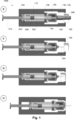
- Figures 1A-K show cut-through views of a first embodiment of the auto injector 100a.
- Figure 1A shows the auto injector 100a without a syringe 200 inserted.
- the auto injector comprises a housing 102 extending from a distal end 103 to a proximal end, where the proximal end 104 is against the patients skin during injection of medicament.
- the first drive module can e.g. be an electrical motor and may be the only motor in the auto injector 100a.
- the auto injector further comprises a rigid needle shield remover 130 extending from a distal end 134 to a proximal end 135.
- the rigid needle shield remover holder 136 is movable in the longitudinal direction relatively to the housing 102 as seen when comparing e.g. figures 1G, 1H, and 1G .
- the rigid needle shield remover 130 shown in figures 1A-K comprises two arms 133 each pivotally attached to needle shield remover holder 136 at the distal end of the arms 134.
- FIGS 1B-J show the auto injector 100a with a syringe positioned inside the syringe holder 110.
- the syringe 200 comprises a syringe compartment 202 extending from a proximal end 201 to a distal end 203. Inside the syringe compartment 202 is the medicament, which is to be administrated to the patient. Also inside the syringe compartment 202 is a stopper 208 movable from a distal position to a proximal position inside the syringe compartment for emptying of the syringe compartment 202. The stopper 208 is moved by a plunger rod 210, which is moving the stopper 208 distally when emptying the syringe compartment 202.
- a hollow needle 204 At the proximal end 201 of the syringe compartment 202 is a hollow needle 204, which is in fluid connection with the syringe compartment and thereby the medicament inside the syringe compartment 202.
- a rigid needle shield 206 Connected to the proximal end 201 of the syringe compartment and covering the hollow needle 204 is a rigid needle shield 206.
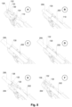
- FIGs 1B-F shows how the rigid needle shield 206 is automatically removed when the syringe 200 is positioned inside the auto injector 100a.
- the syringe 200 has just been inserted into the syringe holder 110 and the rigid needle shield remover 130 is in an open position, where the arms 133 are not touching the syringe 200.
- the drive module can move the syringe holder 110 with the syringe 200 in the distal direction at the same time as the rigid needle shield 130 moves the proximal ends 135 of the arms 133 towards the syringe 200.
- the rigid needle shield remover 130 prevent the rigid needle shield 206 from moving with the syringe compartment 202 further in the distal direction as shown in figures 1E .
- the rigid needle shield remover 130 may have a second part 138 adapted for supporting the rigid needle shield 206 when it has been separated from the syringe compartment 202.
- the second part is shown in more detail in the description of the fifth embodiment of the auto injector in figures 9 .
- Figure 1F show the auto injector with the syringe after the rigid needle shield has been removed therefore exposing the needle 204.
- a skin sensor 150 In front of the needle at the proximal end of the auto injector 100a is a skin sensor 150.
- the skin sensor 150 is moveable relatively to the housing 102 such that when the user presses the skin sensor against the skin for insertion of the needle 204 and the subsequent injection of the medicament, the skin sensor 150 is moved in the distal direction. This brings the skin sensor 150 to a position primarily inside the housing 102 as shown in figure 1G .
- the skin sensor 150 comprises an opening at the proximal end allowing at least the insertion needle 204 to pass through.
- the auto injector 100a as shown in figure 1G is now ready for insertion of the needle 204 and the subsequent injection of the medicament inside the syringe compartment 202.
- the injection of the needle 204 is done by suppressing an activation button 142 (not shown in the figures 1A-K ), which releases a first spring 140 (not shown in the figures 1A-K ) whereby the syringe holder 110 containing the syringe 200 is moved proximally for insertion of the needle 204.
- the activation button may be positioned either outside the housing 102 or inside the housing 102.
- Figure 1H shows the position where the needle 204 has been injected into a patient.
- the rigid needle shield remover 130 and its holder 136 has been moved with the syringe 200 in the proximal direction due to the rigid needle shield remover 130 still having its arms closed in around the needle preventing the syringe compartment 202 from bypassing the rigid needle shield remover 130 in the proximal direction.
- the rigid needle shield remover holder 136 is positioned in contact with a distal surface 114 on the syringe holder 110.
- the plunger rod 210 has been moved in the proximal direction.
- the plunger rod 210 has thereby moved the stopper 208 to its most proximal position whereby the medicament in the syringe compartment 202 has been delivered to the patient.
- the plunger rod 210 may be moved by means of another plunger rod inside the auto injector pressing on the distal end of the syringe plunger rod 210.
- the first drive module may control this movement or it may be controlled by a second drive module.
- the syringe holder 110 After injection of the medicament, the syringe holder 110 is moved distally bringing the empty syringe 200 with the injection needle 204 to a position inside the housing 102 where contact with needle 204 is prevented. This is seen in figure 1J .
- the auto injector is now ready for being removed from the skin of the patient.
- the skin sensor 150 moves in the proximal direction further protecting the user from the needle 204.
- the skin sensor 150 covers the insertion needle 204 after insertion.
- FIG. 1K shows the auto injector 100a after the removal of the syringe 200.
- the syringe holder 110 and the rigid needles shield remover 130 is now back in its original position as shown in figures 1A ready for a new syringe 200 to be positioned inside the auto injector 100a.
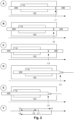
- Figures 2A-E illustrate the longitudinal position of the housing 102, syringe holder 110, and a syringe 200 during the removal of the rigid needle shield 206, and before, during and after injection of medicament in the syringe 200.
- the auto injector is in a primary position L1, which correspond to the position shown in figure 1B or C .
- the drive module then moves the auto injector into a secondary position L2 as shown in figure 2B corresponding to the position of figure 1D , wherein in the secondary position the first part 132 of the rigid needle shield remover 130 is positioned between the rigid needle shield 206 and the proximal end 201 of the syringe compartment 202.
- the auto injector has been moved to a tertiary position L3 by the first drive module, wherein in the tertiary position L3 the rigid needle shield is loosened from the syringe compartment.
- the rigid needle shield 206 in the tertiary position L3 may be sticking 5-15 mm out of the housing 102 for easy manually removal by the user.
- first drive module moved the auto injector to a quinary position L5 as shown in figure 2E corresponding to the position shown in figure 1J . This also corresponds to the tertiary position as show in figure 2C .
- the empty syringe 200 may be removable from the auto injector 100a in this position.
- the syringe holder 110 is moved proximally to the primary position L1 for removal of the empty syringe 200.
- FIGS 3A1-E2 a second embodiment of the auto injector 100b is shown.
- the "1" and “2" images show the auto injector in the same position with the difference being the position where the cut through the auto injector has been made.
- the second embodiment of the auto injector 100b is extending from a distal end 103 to a proximal end, where the proximal end 104.
- the first drive module can e.g. be an electrical motor and may be the only motor in the auto injector 100b.
- the auto injector comprises a rigid needle shield remover 130 similar to the one described for the first embodiment.
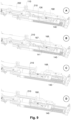
- the removal of the rigid needle shield constitutes the differentiating feature between the first and the second embodiment, as the second embodiment 100b comprises a gear rack system 160 positioned inside the housing 102.
- the gear rack 160 system comprises three rack parts; a first gear rack part 162, a second gear rack part 154 and a third gear rack
- the first gear rack part 162 is displaceable relatively to the housing 102. As shown in figures 3A1-E2 , the first gear rack is extending inside a channel extending in the longitudinally direction inside the housing 102.
- the second gear rack part 164 is connected to the housing 102 and in geared connection with the first gear rack part 162.
- the second gear rack part is a wheel, which turns around a central axis connected to the housing 102.
- the third gear rack part 166 is part of the rigid needle shield remover holder 136 to which the needle shield remover 130 is connected.
- the third gear rack part 166 is displaceable relatively to the housing 102 and is in geared connection with the second gear rack part 164.
- the second gear rack part 164 connects the first gear rack part 162 and the third gear rack part 166 thereby transferring movement of the first gear rack part 162 to the third gear rack part 166.
- the auto injector 100b further comprises a cover 170 which the user can remove from and connect to the housing 102 again after a syringe 200 has been positioned inside the housing 102.
- the cover 170 can be (manually) moved in the distal direction into a cover channel in the housing 102. Putting the cover onto the auto injector 100b after positioning a syringe 200 inside the housing 102 makes the rigid needle shield arms 133 to move into the gap between syringe 200 and the rigid needle shield 206.
- the cover 102 forces the first gear rack part 162 to move along with it in the distal direction due to the connecting finger 163 as shown by comparing figures 3B1-2 and 3C1-2 .
- the movement of the first gear rack 162 distally causes the second gear rack part 164 to rotate whereby the third gear rack part 166 is moved in the proximal direction due to the geared connection between the first/second gear rack parts 162/164 and the second/third gear rack parts 164/166.
- the first gear rack part 162 causes the third gear rack part 166 to move in the opposite direction with half speed and double force.
- the auto injector 100b further comprises two rack springs; a first rack spring 152 and a second rack spring 154.
- the first rack spring 152 is positioned inside the same channel as the first gear rack part 162 to which it is directly connected to the distal end of the first gear rack part 162.
- the second rack spring 154 is connected to the rigid needle shield remover holder 136 extending around a part of it as shown in figures 3A2 , 3C2 , 3D2 , and 3E2 .
- the rack springs 152, 154 are omitted for a clearer view of the remaining parts.
- Movement of the first gear rack 162 in the distal direction by means of pushing the cover 170 in the distal direction, thereby causes the first track spring 162 to compress as is shown in figure 3C1-2 and 3D1-2 .
- the second rack spring 154 is compressed due to the movement of the third gear rack part 166 in the proximal direction, the latter being a consequence of the gear connection to the first and second gear rack parts 162, 164.
- the rigid needle shield remover holder 136 When the cover 170 is moved distally inside the auto injector 100b, the rigid needle shield remover holder 136 is moved proximally pushing the rigid needle shield 206 with it in the proximal direction. This loosens the rigid needle shield 206 from the proximal end 201 of the syringe compartment 202 and the rigid needle shield can now the (manually) removed from the auto injector with the syringe 200 in the positions shown in figures 3C1-D2 .
- first gear rack part 162 is moved against its distal limit, whereby the connecting fingers are forced out of contact with the cover 170 thereby breaking the connection between cover 170 and the first gear rack part 162.
- the first rack spring 152 and the second gear rack spring 154 are released allowing the gear rack system 160 to reset as the springs 152, 154 relaxes from the compressed positions shown in figures 3C1-3D2 .
- the rigid needle shield remover is opened up as shown in figures 3E1-2 allowing for insertion of the needle 204 and the subsequent injection of the medicament as described for the first embodiment of the auto injector 100a.
- the first gear rack part 162 lies extended alongside the cover 170 inside the housing 102 with the connection fingers pointing straight forward in the proximal direction.
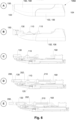
- Figures 4A-F shows a third embodiment of the auto injector 100c, where figure 4A shows the auto injector 100c without a syringe 200 and figures 4B-F shows the auto injector with the syringe 200 inserted.
- the auto injector 100c comprises a housing 102 extending from a distal end 103 to a proximal end 104, where the proximal end 104 is against the patients skin during injection of medicament.
- the first drive module can e.g. be an electrical motor and may be the only motor in the auto injector 100c.
- the auto injector further comprises a rigid needle shield remover 130 similarly to the one described in the previous embodiments.
- the rigid needle shield 130 is connected to a rigid needle shield remover holder 136, which forms part of the housing 102.
- the rigid needle shield remover holder 136 of the third embodiment of the auto injector 100c is not movable in re to the housing 102.
- the syringe holder 110 is in the initial position furthest to the distal end inside the housing 102 as shown in figure 4A .
- the auto injector 100c is now ready for receiving a syringe 200.
- the rigid needle shield remover 130 is in an open position in this embodiment.
- Figure 4B shows the auto injector 100c with a syringe 200 positioned in the syringe holder 110.
- the syringe holder 110 with the syringe 200 has been moved in the proximal direction by the drive module. This movement brings the syringe holder 110 into a position corresponding to the primary position L1 as shown and described in figures 2A and 2F .
- the rigid needle shield remover 130 is moving into a position between the rigid needle shield 206 and the proximal end 201 of the syringe compartment 202.
- Figure 4E shows the auto injector 100c in a position where the drive module has the syringe holder 110 further in the distal direction without moving the rigid needle shield remover 130. This loosens the rigid needle shield 206 from the syringe 200.
- the position corresponds to the tertiary position shown and described in figures 2C and 2F . In this position, the rigid needle shield 206 can be removed by the user.
- the rigid needle shield remover 130 has opened up its arms 133 again and the auto injector is ready for insertion of the needle as described in the first embodiment.
- All the embodiments of the auto injector described above further comprises a syringe sensor 144 (not shown in the figures) adapted for detecting when a syringe 200 is positioned in the syringe holder 110.
- the syringe sensor 144 can be positioned inside the housing 102 of the auto injector.
- the syringe sensor can be positioned in different locations inside the housing 102 or the syringe holder 110.
- a cover e.g. a part of the housing, which is removed when placing eh syringe inside the auto injector as discussed in the fourth embodiment of the auto injector
- Placing a cover onto the auto injector 102 after positioning of a syringe 200 inside the syringe holder 110 may activate the drive module thereby starting the movement of the syringe holder 110 as described in the above embodiments.
- All the embodiments of the auto injector described above further may comprise a rigid needle shield sensor 146 adapted for detecting if the rigid needle shield 206 is attached to the syringe compartment 200.
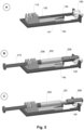
- Figures 5A-C show an example of a rigid needle shield sensor 146 connected to the syringe holder 110 in an auto injector 100a, 100b, 100c.
- the distal end 147 of the rigid needle shield sensor 146 is connected to the syringe holder 110 and the proximal end 148 of the rigid needle shield sensor 146 is in contact with the rigid needle shield 206 when the rigid needle shield 206 is connected to the syringe 200 as shown in figure 5B .
- the rigid needle shield sensor 146 may be connected to the syringe holder 110 at the different location or be connected to a part of the housing 102.
- One or more additional rigid needle shield sensors adapted for detecting if the rigid needle shield is attached to the syringe may also be present at one or more different locations along the length of the rigid needle shield 206 when positioned inside the auto injector.
- the rigid needle shield sensor 146 shown in figures 5A-C is a spring loaded rotatable arm connected to an electronic switch (not shown).
- the rotatable arm is in a depressed position as shown in figure 5B when the rigid needle shield 206 is connected to the syringe compartment 202.
- the rotatable arm interacts with the electronic switch thereby allowing electronics to detect the presence of the rigid needle shield 206.
- the rigid needle shield sensor 146 is allowed to relax again as shown in figure 5C and the electronic connection to the electronic switch breaks.
- information about whether the rigid needle shield is mounted or fully dismounted from the syringe is important before allowing the user to attempt injection of the medication. If the rigid needle shield still sits on the tip of the syringe compartment when the user attempts insertion of the needle and the subsequent injection of medicament, then potentially no medication would be delivered into the patient.
- the rigid needle shield sensor 146 only detects the presence of the rigid needle shield 206 close to the syringe compartment 202, however one could easily imagine a design where the rigid needle shield sensor 146 interacts further out (e.g. around the area of the needle tip) whereby even if pulled off but not fully removed, the rigid needle shield 206 would be detectable by the rigid needle shield sensor 146.
- Figure 6A shows a fourth embodiment of the auto injector 100d comprising a housing 102 extending from a proximal end 103 to a distal end 104.
- the housing comprises two parts; a first part 106 and a second part 108, the latter forming a removable cover, which allows for the positioning of a syringe inside the auto injector 100d.
- Alternative designs may have the housing constructed as a one-piece item.
- FIG 6B the housing cover part 108 shown in figure 6A has been removed showing the syringe holder 110 and the rigid needle shield remover 130 inside the housing 102 of the auto injector 100d.
- FIG 6C the first part of the housing 106 and the skin sensor 150 has also been removed whereby the syringe holder 110 and the rigid needle shield remover 130 is seen more clearly.
- the piston 168 of the auto injector 100d can also be seen in figure 6C .
- the piston 168 of the auto injector 100d is adapted for moving the plunger rod 210 in the syringe 200 proximally for injection of medicament.
- a plate or similar in the auto injector may move the plunger rod 210 of the syringe in the proximal direction.
- a syringe 200 has placed in the syringe holder 110 and in figure 6E , the syringe 200 has been moved in the proximal direction by the first drive module 120, whereby the rigid needle shield 206 is in a position for easy removal from the syringe compartment 202.
- Figures 7A-D show the auto injector 100d with a syringe 200 during the loosening of the rigid needle shield 206 from the syringe compartment 202.
- the syringe 200 and the syringe holder 110 is in a forward position.
- the rigid needle shield remover 130 retains the rigid needle shield in the position shown in figure 7A thereby loosening the rigid needle shield 206 from the syringe compartment 202.
- the rigid needle shield can be removed from the syringe compartment 202 as shown in figure 7D , which exposes the insertion needle 204.
- the drive module also moves the piston 168 of the auto injector in the distal direction comparing figures 7A-D .
- FIGs 8A-F show a close up of the outer proximal end of the auto injector during the removal of the rigid needle shield.
- the rigid needle shield remover 130 can be seen before a syringe 200 is positioned in the auto injector 100d.
- the first part 132 of the rigid needle shield remover 130 which is adapted for being positioned between the rigid needle shield and the syringe compartment 202 is clearly visible as a part of the rigid needle shield remover arms 133.
- the second part 138 of the rigid needle shield remover 130 is adapted for holding the rigid needle shield 206 such that it does not accidentally fall of the syringe after separation from the syringe compartment 202.
- the syringe 200 has been positioned inside the auto injector 100d.
- the syringe 200 is in a retracted position and the rigid needle shield remover 130 is not positioned between the rigid needle shield 206 and the syringe compartment 202 yet.
- the syringe 200 is in a forward position from where a distal movement of the syringe 202 positions the first part 132 of the rigid needle shield remover 130 between the rigid needle shield 206 and the syringe compartment 202 as shown in figure 8D .
- the detection of the presence of a syringe and a rigid needle shield may be obtained using a syringe sensor and a rigid needle shield sensor as described above, e.g. in connection with figures 5A-C .
- the rigid needle shield remover arms 133 are pushes centrally at the proximal end by an arm spring, which is not visible in the figures 8A-F .
- the spring biased configuration provides support to the rigid needle shield remover after the manual removal of the rigid needle shield.
- the spring biased arms 133 do not interfere with syringe movements and injection procedures and they do not interfere with syringe loading or unloading either due to the rounded edges on top of the arms 133.
- the arms 133 can be substantially linear as shown in figures 8A-F or L-shaped as shown in the first three embodiments of the auto injector 100a, 100b, 100c.
- the rigid needle shield sensor 146 may be adapted for detecting the angular rotation of the two arms 133 towards each other.
- Figures 9A-D shows a mechanism of insertion of the needle and the subsequent injection of medicament, according to the present invention.
- the auto injection 100d is in a position ready for activation by pressing an activation button.
- the drive module 120 moves the piston 168 proximally.
- a release finger 167 on the piston rod 168 releases the first spring 140 (see figure 9B ).
- the first spring 140 forces the syringe holder forward thereby inserting the needle 204.
- Figure 9C shows the auto injector 100d directly after injection of the needle 204.
- the drive module 120 continues to move the piston 168 forward in the proximal direction.
- the piston 168 catches up with the plunger rod 210, it continues to move the plunger rod 210 (which in turn moves the stopper 208) in the proximal direction thereby delivering the medicament to the patient. This is shown in figure 9D .
- the first spring 140 is moving at a needle insertion speed
- the drive module is moving the piston at a medicament delivery speed, wherein the needle insertion speed is larger than the medicament delivery speed, whereby the piston 168 and the plunger rod 210 is separated in the longitudinal direction during and for a time period after insertion of the needle 204 before the piston 168 catches up with the syringe compartment 202.
- the auto injector 100d may further comprising a second spring exerting a pressure on the skin sensor 150 in the proximal direction after removal of the auto injector 100d from the skin post injection of the medicament. This pushes the skin sensor 150 in the proximal direction locking the skin sensor 150 in a position where it covers the needle 204 to prevent accidental contact with the needle 204 after injection of medicament.
- Figure 10 shows interior parts of the auto injector 100d connected to a cassette syringe 200 in a perspective view from the distal end.
- the drive module 120 can be seen.
- the drive module comprises a motor 122 and a gear box 124 connected to a screw 126.
- the piston 168 is connected to a chassis 180, which in turn is connected to the drive module 120.
- the syringe holder 110 is connected to a slider 190.
- Figures 11A-C show a fifth embodiment of the auto injector 100e comprising a housing 102 extending from a proximal end 103 to a distal end 104.
- the two housing parts; the first part 106 and the second part 108, are visible.
- the second housing part 108 is not necessarily removable as a cassette 400 can be front loaded into the auto injector 100e.
- the housing can be a one-piece item.
- the cassette 400 is visible in figure 11A , where the cassette skin sensor 450 is extending outside the proximal end 103 of the housing 102.
- the activation button 142 is also viewable in figure 11A .
- the housing 102 has been partly omitted for a clearer view inside the auto injector 102, where the piston 168, the cassette receiver 172 and the cassette with the cassette skin sensor 450 and the rigid needle shield holder 430 can be seen.
- the cassette 400 is described in more detail in the figures 12-24 .
- FIG 11C a cut through view of the auto injector 100e with the cassette 400 is shown in a perspective view.
- figure 11D a cut through view of the auto injector 100e with the cassette 400 after the rigid needle shield 206 has been removed is shown in a side view.
- the first spring 140 which is for insertion of the needle 204, can be seen.
- FIG 23 and 24 the connection between cassette 400 and the auto injector 100d is described in further details with figure 24 displaying the locking of the two part by a first snap fit joint.
- the cassette receiver 172 shown in figure 11B is configured to receive a cassette 400
- the piston 168 is configured for moving the stopper 208 inside the syringe 200 of the cassette 400 proximally thereby emptying the syringe of medicament
- the drive module (see figures 25A-B ) is adapted to move the piston 168 and the cassette receiver 172.
- the piston and the cassette receiver can be moved together or separately by the drive module.
- the first spring (see figure 25B ) is adapted for moving the syringe holder 410 with the syringe compartment 202 connected to the needle 204 proximally for insertion of the needle 204.
- the drive module 120 is further configured for moving the syringe compartment 202, the syringe holder 410 and the cassette skin sensor 450 in the distal direction relative to the rigid needle shield holder 430 and the rigid needle shield 206 thereby allowing for removal of the rigid needle shield 206.
- Figure 12 shows a close-up of the cassette 400, which comprises a syringe compartment 202 containing the medicament and extending from a proximal end 201 to a distal end 203, a hollow needle 204 in fluid connection with the proximal end 201 of the syringe compartment 202, a rigid needle shield 206 connected to the proximal end 201 of the syringe compartment 202 and covering the hollow needle 204, and a stopper 208 movable from a distal position to a proximal position inside the syringe compartment 202 by means of the piston 168 moving the stopper 208 proximally for emptying the syringe compartment.
- the cassette 400 further comprises a syringe holder 410 extending around at least part of the syringe compartment 202, a rigid needle shield holder 430 having a first part 431 positioned between the rigid needle shield and the proximal end of the syringe compartment, and a cassette skin sensor 450 positioned at the proximal end of the cassette 400.
- the cassette is normally absent of springs.
- FIG. 13 shows the syringe 200 with the syringe compartment 202 and the needle 204
- figure 14 shows the rigid needle shield 206
- figure 15 shows the rigid needle shield holder 430
- figure 16 shows the combination of the syringe 200, the rigid needle shield 206, and the rigid needle shield holder 430
- Figure 17 shows the syringe holder 410
- figure 18 shows the combination of the syringe 200, the rigid needle shield 206, the rigid needle shield holder 430 and the syringe holder 410.
- Figures 19A-B show the cassette skin sensor with figure 18B being a cut-through view showing the inside of the cassette skin sensor.
- Figure 20 shows the combination of the syringe 200, the rigid needle shield 206, the rigid needle shield holder 430, the syringe holder 410 and the cassette skin sensor 450
- figure 21 shows a close-up of the cassette 400 in a position where the cassette skin sensor 450, the rigid needle shield holder 430 and the syringe holder 410 are locked together.
- the rigid needle shield holder 430 is contained partly inside the syringe holder 410.
- the cassette skin sensor 450 is extending partly around the syringe holder 410 and the rigid needle shield holder 430.
- the syringe holder 410 and the cassette skin sensor 450 are moveable in the distal direction relative to the rigid needle shield holder 430 and the rigid needle shield 206.
- the cassette skin sensor 450 covers the rigid needle shield 206 in the first position shown in figure 12 , which corresponds to the cassette 400 before being placed in the auto injector 100d.
- the drive module 120 of the auto injector 100d moves the cassette skin sensor 450 in the distal direction relative to the rigid needle shield 206. This exposes the rigid needle shield 206 since it is held in position by the rigid needle shield holder 430. In this second position, at least a proximal part of the rigid needle shield 206 is exposed allowing the rigid needle shield 206 to be removed by the user.
- the rigid needle shield holder 430 is attached to the syringe holder 410 by a second snap joint 424, 444, which can be seen in figure 18 .
- the syringe holder 410 comprises one or more proximally extending arms 424 as also seen in figure 17 .
- the rigid needle shield holder 430 comprises one or more distally extending protrusions 444.
- Figure 18 shows how the one or more proximally extending arms 424 of the syringe holder 410 locks to the one or more distally extending protrusions 444 of the rigid needle shield holder 430 thereby forming the second snap joint 424, 444.
- the second snap joint 424, 444 is released upon movement of the syringe holder 410 distally relative to the rigid needle shield holder 430.
- the auto injector 100e comprises a chassis adapted for retaining the rigid needle shield holder 430 while the syringe holder 410 is moved distally thereby releasing the second snap fit.
- the cassette skin sensor 450 is locked to the syringe holder 410 by a third snap joint 411, 451 as shown in figure 20 .
- the third snap joint is formed by a first support surface 411 on the syringe holder 410 and an arm 451 on the cassette skin sensor 450, wherein the arm 451 of the cassette skin sensor 450 rests against the first support surface 411 of the syringe holder 410 thereby forming the third snap joint 411, 451.
- the third snap joint is released by movement of the cassette skin sensor 450 distally relative to the rigid needle shield holder 430.
- the arm 451 of the cassette skin sensor 450 is released from the first support surface 411 of the syringe holder 410 by an inclining surface 440 on the rigid needle shield holder 430.
- the surface 440 on the rigid needle shield holder 430 is clearly visible in figure 16 and figure 19B shows the internal side of the arm 451 on the cassette skin sensor 450, which shows the first proximal surface 452 of the arm 451.
- a second spring in the auto injector 100e exerts a pressure on the cassette skin sensor 450 in the proximal direction. This locks the cassette skin sensor 450, the rigid needle shield holder 430, and the syringe holder 410 to each other positioning the cassette skin sensor 450 in a proximal position covering the needle 204. This prevents the user from accidentally getting in contact with the needle 204 after injection.
- the locking can be seen in a close up in figure 21 , and is described in detail below.
- the rigid needle shield holder 430 comprises a first distal surface 432 as shown in figure 15 and 16 . After delivery of the medicament, the first proximal surface 452 of the cassette skin sensor arm 451 and the first distal surface 432 of the rigid needle shield holder 430 abuts thereby preventing the cassette skin sensor 450 from moving proximally in relation to the rigid needle shield holder 430.
- the cassette skin sensor 450 comprises a first distal surface 454 as shown in figure 19B
- the rigid needle shield holder 430 comprises a first proximal surface 434 as shown in figure 15 .
- the first distal surface 454 of the cassette skin sensor 450 and the first proximal surface 434 of the rigid needle shield holder 430 abuts thereby preventing the rigid needle shield holder 430 from moving proximally in relation to the cassette skin sensor 450.
- the cassette skin sensor 450 comprises a second proximal surface 456 as shown in figure 19B
- the rigid needle shield holder 430 comprises a second distal surface 436 as shown in figure 15 .
- the cassette skin sensor 450 comprises a second distal surface 458 as shown in figure 19B
- the syringe holder 410 comprises a first proximal surface 418 as shown in figure 17 .
- the second distal surface 458 of the cassette skin sensor 450 and the first proximal surface 418 of the syringe holder 410 abuts thereby preventing the cassette skin sensor 450 from moving distally in relation to the syringe holder 410.
- the arm 451 of the cassette skin sensor 450 comprises a first proximal surface 452 as shown in figure 19B
- the syringe holder 410 comprises a first distal surface 412 as shown in figure 17 .
- the first proximal surface 452 of the cassette skin sensor arm 451 and the first distal surface 412 of the syringe holder 410 abuts thereby preventing the syringe holder 410 from moving distally in relation to the cassette skin sensor 450.
- the cassette 400 may further comprise a rigid needle shield sensor 446 adapted for detecting if the rigid needle shield 206 is attached to the syringe compartment 202 or not.
- the rigid needle shield sensor 446 is not shown in the figures, but it may easily be understood that a sensor as described in connection with figure 5A-C could be included in the cassette 400.
- the rigid needle shield sensor 446 may be connected to the rigid needle shield holder 430. In such a setup, a distal end 447 of the rigid needle shield sensor 446 may be connected to the rigid needle shield holder 430 and a proximal end 448 of the rigid needle shield sensor 446 may be in contact with the rigid needle shield 206 when the rigid needle shield 206 is connected to the syringe compartment 202.
- This provides a cassette with a rigid needle shield sensor similar to the one described in connection with figure 5A-C .
- Figures 22A-D show the cassette 400 during selected steps during insertion of the needle and the injection of the medicament.
- the cassette 400 is shown after removal of the rigid needle shield ready for insertion for the needle 204.
- the syringe holder 410 has been moved proximally compared to the rigid needle shield holder 430 and the cassette skin sensor 450, whereby the needle 204 has been inserted into the patient.
- the medicament has not yet been delivered.
- the stopper 208 has been moved forward and the medicament delivered to the patient.
- Figure 23 show the cassette receiver 172 in the fifth embodiment of the auto injector 100e in a close up.
- the distal end of the syringe holder 410 is locked to the cassette receiver 172 by a first snap joint 174, 422 when the cassette 400 is loaded into the auto injector 100e.
- the first snap joint is constructed such that it allows for release of the cassette 400 from the cassette receiver 172 when the piston 168 is in a first position as shown in figure 24 .
- the distal end 420 of the syringe holder 410 comprises an inner recess 422, which the locking arms 174 on the cassette receiver 172 snaps into as shown in figure 24 .
- the piston 168 comprises a constricted portion 169, which is positioned such that locking arms 174 on the cassette receiver 172 can be flexed thereby allowing for the syringe holder 410 to be attached to the cassette receiver 172.
- the constricted portion 169 moves away from the locking arms 174. This locks the cassette 400 to the cassette receiver 172 since the locking arms 174 is now prevented from flexing, which is required in order to release the inner recess 422 from the locking arms 174.
- Figure 25A shows interior parts of the auto injector 100e connected to a cassette 400 in a view from the distal end.
- Figure 25B shows a side cut-through view of the parts shown in figure 25A .
- the drive module 120 can be seen.
- the drive module comprises a motor 122 and a gear box 124 connected to a screw 126.
- the piston 168 shown in figure 25A is connected to a chassis 180, which in turn is connected to the drive module 120.
- the cassette receiver 172 connected to a slider 190 is also seen in figure 25A .
- a light panel 176 is further visible. The panel may provide the user with visual information. Alternatively, audio feedback may be provided to the user from the panel.
- a sensor system 177 comprising a skin sensor switch 178 and a cassette sensor switch 179 is also seen.
- Figures 25C-D show enlargement of the sensor system 177.
- the skin sensor switch 178 is open and cassette sensor switch 179 is close corresponding to the situation where no cassette 400 is placed in the auto injector 100e.
- the skin sensor switch 178 and cassette sensor switch 179 are both is open corresponding to the situation where a cassette 400 has been placed in the auto injector 100e.
- the switches are opened and closed as an actuator component 175 is being pushed in the longitudinal direction by the skin sensor 450 in the cassette 400.
- Figure 26A shows the piston 168
- figure 26B the chassis 180
- figure 26C shows the piston 168 connected to the chassis 180 in a bottom-up view.
- FIG 27 shows the slider 190 to which the cassette receiver 172 (not shown in the figure) is attached.
- Figure 28 shows close-up of the chassis 180 and the slider 190 locked together.
- the chassis 180 comprises a locking surface 182, which a locking arm 192 on the slider 190 abuts creating a locked connection.
- the drive module 120 moves the chassis 180 with the piston 168 in the distal direction after loading of a cassette 400 in the auto injector 100e
- the locking surface 182 comes in contact with the locking arm 192 on the slider 190, the slider 190 is also moved distally. In this position, the piston 168 has reached a position where it non-releasable locks the cassette to the cassette receiver 172.
- the rigid needle shield holder 430 (not shown in this figure) is resting against a hard stop in the chassis and cannot move into the auto injector 100e.
- the remaining components of the cassette can move into the auto injector 100e, when the slider 190 moves proximally.
- the drive module 120 moves the chassis 180 proximally for insertion of the needle and injection of medicament.
- the locking arm 192 is released from the locking surface 182 during this movement allowing the first spring 140 to push the slider 190 with the cassette 400 forward thereby inserting the needle 204.
- the drive module 120 continues to move the chassis with the plunger rod forward in the proximal direction.
- the piston 168 catches up with the cassette 400, it continues to move the stopper 208 in the proximal direction thereby delivering the medicament to the patient.
- the first spring 140 is thereby moving at a needle insertion speed
- the drive module is moving the piston at a medicament delivery speed, wherein the needle insertion speed is larger than the medicament delivery speed, whereby the piston168 and the stopper 208 is separated in the longitudinal direction during and for a time period after insertion of the needle 204 before the piston 168 catches up with the syringe compartment 202.
- This is also shown and discussed in connection with figures 9A-D .
- the auto injector may further comprising a second spring exerting a pressure on the cassette skin sensor 450 in the proximal direction after removal of the auto injector 100e from the skin post injection of the medicament. This pushes the skin sensor 450 in the proximal direction locking the cassette parts together as described in connection with figure 21 .
- Figure 29A shows a sixth embodiment of a cassette 500 in an exploded view.
- the auto injector 100f for receiving the cassette 500 is shown in figures 31-35 .
- a syringe 200 with a syringe compartment 202 containing the medicament a hollow needle 204 in fluid connection with the syringe compartment, a rigid needle shield 206 connected to the proximal end of the syringe compartment and covering the hollow needle, and a stopper 208 movable from a distal position to a proximal position inside the syringe compartment 202 by means of a piston in the auto injector.
- the needle shield 206 shown in figure 29A has both an outer part 206, and an inner part 207.
- the parts may normally be a connected or even produced as a one-piece item.
- a syringe holder 510 Positioned around the syringe 200 is a syringe holder 510 extending around at least part of the syringe compartment 202.
- the syringe holder 510 has a syringe holder support tube 511, which supports the syringe compartment 202.
- the tube 511 has an opening for inspection of the medicament in the syringe compartment 202.
- the syringe 200 is fixed inside the syringe holder 510 at the end 205 of the syringe 200, which has a collar-like shape.
- a ring-shaped syringe holder part 519 may be used for securing the syringe 200 inside the syringe holder 510. This may also be omitted.
- the cassette 500 comprises a cassette housing 540 extending from a proximal 541 to a distal end 542.
- the cassette housing 540 is oval, which helps ensure an accurate positioning of the cassette 500 inside the auto injector 100f.
- the oval shape may also make the cassette more compact.
- the cassette housing 540 is enclosing a cassette skin sensor 550.
- a cassette housing shoulder 546 At the proximal end 541 of the cassette housing 540 is a housing shoulder 546 with an opening 545 through which the cassette skin sensor 540 can extend.
- the cassette housing 540 have internal protruding rails 548 (not shown in the figure) on its inside for guiding the skin sensor 550.
- the two parts 540, 550 are movable in relation to each other in an unlocked configuration.
- the cassette skin sensor 550 is positioned such that it extends proximally from the cassette housing 540.
- the cassette housing 540 has a distal end surface 543 with a skin sensor housing opening 545 through which the cassette skin sensor 550 extends. This is most clearly seen in the cut-through images, e.g. in figure 30 .
- the cassette housing 540 has an opening 547 in the longitudinal direction for inspection of the medicament in the cassette 500.
- the cassette skin sensor 550 has two pins; a first skin sensor pin 557 and a second skin sensor pin 558, extending from the distal end 552 of the cassette skin sensor 550.
- the cassette skin sensor 550 covers at least part if not the majority of a syringe holder 510, which is shown in more details in figures 29B-C in a front-end and a rear-end perspective view.
- the syringe holder 510 has an elongated tubular part 511 with an opening for inspection of the medicament.
- a ring-shaped syringe holder part 519 At the distal end 509 of the syringe holder 510 is a ring-shaped syringe holder part 519, which has a number of openings including: a first pin opening 526, a second pin opening 527, a third pin opening 528, a fourth pin opening 529, and a piston opening 525. It is through the piston opening 525 that the auto injector piston 1168 extends when medicament is delivered to the patient.
- the syringe holder 510 also comprises a first syringe holder arm 512 extending in a proximal direction from the ring-shaped syringe holder part 519.
- the first syringe holder arm 512 has a proximal surface 514 at the proximal end of the arm 512.
- a first locking protrusion 553 on the cassette skin sensor 550 engages with the proximal surface 514. This engagement of the first locking protrusion 553 and the proximal surface 514 prevents movement of the cassette skin sensor 550 towards the syringe holder 510.
- the first syringe holder arm 512 is flexibly connected to the ring-shaped syringe holder part 519.
- the syringe holder 510 also comprises a syringe holder ring 507, which locks the syringe 200 inside the syringe holder 510.
- the first pin opening 526 allows for passage of a first skin sensor release pin 1156 of the auto injector 100f there through. This is seen and described in connection with e.g. figures 35A-F .
- the first skin sensor release pin 1156 of the auto injector 100f passes through the first pin opening 526 in the syringe holder 510, it comes in contact with the first syringe holder arm 512 and deflects it. This causes a release of the cassette skin sensor 550 allowing it to move towards the syringe holder 510, i.e. a distal direction movement of the cassette skin sensor 550.
- the first cassette skin sensor pin 557 moves towards - and possibly through - the second pin opening 527 in the syringe holder 510.
- the second cassette skin sensor pin 558 moves towards - and possibly through - the third pin opening 528 in the syringe holder 510 when the cassette skin sensor 558 moves distally.
- the syringe holder 510 and the skin sensor 550 are longitudinally movable relative to each other upon release of the skin sensor 550 from the syringe holder 510.
- the syringe holder 510 also has a second syringe holder arm 516 extending in a proximal direction from the ring-shaped syringe holder part 519 (see figure 35G ).
- the second syringe holder arm 516 comprises a distal surface 518 at the proximal end of the arm.
- the distal surface 518 is resting against a second locking protrusion 554 on the cassette skin sensor 550. This engagement prevents movement of the cassette skin sensor 550 away from the syringe holder 510.
- the two parts are thus prevented from both moving towards and away from each other.
- the second syringe holder arm 516 is also flexibly connected to the ring-shaped syringe holder part 519.
- a second skin sensor release pin 1159 of the auto injector 100f is pushed through the fourth pin opening 529, it comes in contact with the second syringe holder arm 516 (see figure 35G ).
- the third pin opening 528 allows passage of a skin sensor forward pin 1158 of the auto injector 100f (see figures 35A-F ), which pushes on the second cassette skin sensor pin 558 of the cassette skin sensor 550.
- the second cassette skin sensor pin 558 may also pass through the third pin opening 528 before coming in contact with the skin sensor forward pin 1158.
- the syringe holder 510 has two syringe holder locking protrusions 524 fitting into openings 544 at the distal end 541 of the cassette housing 540. This locks the syringe holder 510 and the cassette housing 540 together. More locking protrusions/openings could also be imagined.
- the syringe holder 510 further comprises one or more cassette locking protrusions 539 locking the syringe 200 to the cassette 500.
- the cassette 500 further has a rigid needle shield holder 530 having a first part 531 positioned between the rigid needle shield 206 and the proximal end of the syringe compartment 201.
- the rigid needle shield holder 530 comprises an inner rigid needle shield tube 535 with the first part 531 and an outer an outer rigid needle shield tube 536. This is most clearly seen in figures 34A-C .
- the outer rigid needle shield tube 536 surrounds the inner rigid needle shield tube 535, and the inner rigid needle shield tube 535 surrounds the rigid needle shield 206.
- the outer rigid needle shield tube 536 abuts the housing shoulder 546 of the cassette housing 540 as shown in figure 30 .
- the proximal end 560 of the cassette skin sensor 550 is positioned between the inner rigid needle shield tube 535 and the outer rigid needle shield tube 536 as shown in figure 30 .
- the rigid needle shield holder 530 is removable from the syringe compartment 202, and wherein when the rigid needle shield holder 530 is removed, the rigid needle shield 206 follows with it, whereby the hollow needle 204 is exposed.
- the rigid needle shield holder 530 therefore functions as both a cassette cap and a rigid needle shield holder.
- Figures 31-32 show a sixth embodiment of an auto injector for receiving the cassette of figures 29-30 .
- the auto injector 100f is shown in an exploded view in figure 31
- figures 32A-B show the assembled auto injector 100f.
- the outer housing 1102 has been omitted.
- the outer housing 1102 can be seen in figures 34A-D .
- the auto injector 100f extends from a proximal end to a distal end and comprises the housing 1102 extending from a proximal end 1103 to a distal end 1104.
- the housing is in one piece in this embodiment of the auto injector.
- the cassette 500 is loaded into the auto injector in a front-loading configuration.
- the auto injector comprises a cassette receiver 1110 configured to receive the cassette 500.
- the cassette 500 is interfacing with the auto injector 100f at the distal end of the cassette 500, whereby the two part are sharing the same longitudinal axis. This mitigates the risk of the cassette getting stuck inside in the auto injector. Further, it makes the connection as slim as possible.
- the only auto injector element, which extends in parallel with the cassette 500 is normally the injector housing 1102. Inside the auto injector 100f, is a drive module 1150, which is adapted to move a piston 1168. The piston 1168 is moved proximally pushing on the stopper 208 inside the syringe whereby medicament can be expelled from the syringe.
- the piston 1168 has an inner threading (not shown in the figures), which engages with an outer threading on a led screw 1169.
- the drive module 1150 includes a motor 1151, which through a gear assembly 1153, rotates the led screw 1151.
- the gear assembly 1153 is covered by a gear cover 1152, some O-rings 1155 and a chassis cover 1154.
- the drive element 1150 also controls the movement of a number of pins comprised in the auto injector 100f.
- the number of pins include; a first skin sensor release pin 1156, a skin sensor forward pin 1158, a second skin sensor release pin 1159, and a cassette detection pin 1160.
- the drive module 1150 is further configured for moving the first skin sensor release pin 1156, the skin sensor forward pin 1158, the second skin sensor release pin 1159, and the cassette detection pin 1160 proximally.
- the spring system 1140 includes a spring guidance pin 1141 around which a supporting chassis 1142 connected to the skin sensor forward pin 1158 is found. Extending around the guidance pin 1141 is also a spring 1143. When the spring 1143 is allowed to relax, it pushes the supporting chassis 1142 forward, which in turn pushes the skin sensor forward pin 1158 proximally. Inside the skin sensor forward pin 1158 at the distal end thereof is a guide pin 1161 for the skin sensor forward pin 1158. When the skin sensor spring system 1140 pushes the cassette skin sensor 550 proximally after delivery of medicament, it is pushed into a locked position preventing distal movement of the cassette skin sensor 550.
- the auto injector 100f also comprises a cassette receiver 1110 configured to receive a cassette.
- the cassette receiver is in the shape of a chassis as seen in figures 31 and 33 , the latter showing an enlarged view of the cassette receiving chassis 1110.
- the cassette receiving chassis 1110 is extending from a proximal end 1111 to a distal end 1112.
- a ring-shaped chassis part 1114 At the proximal end 1111 of the chassis 1110, is a ring-shaped chassis part 1114 with a number of openings including a piston opening 1115, a first pin opening 1116, a second pin opening 1117, a third pin opening 1118, a fourth pin opening 1119, and a fifth opening 1120.
- the piston opening 1115 is aligned with piston opening 525 in the syringe holder 510 to allow the auto injector piston 1168 to extend there through.
- the first pin opening 526 in the syringe holder 510 is aligned with the first pin opening 1116 such that the first skin sensor release pin 1156 can pass through both openings to deflect the first syringe holder arm 512 thereby unlocking the cassette skin sensor 550 from the syringe holder 510.
- the second pin opening 1117 in the a ring-shaped chassis part 1114 is aligned with the second pin opening 527 in the syringe holder 510 for allowing passage of the first cassette skin sensor pin 557 of the cassette skin sensor 550 to pass there through.
- the second pin opening 1117 does not extend all the way through, but instead has an end surface 1121 (see figure 35G ), which stops the first cassette skin sensor pin 557 of the cassette skin sensor 550 in its distal movement towards the auto injector.
- the second pin opening 1117 is a well-shaped opening with an end surface 1121 limiting the distal movement of the first cassette sensor pin 557 and thereby the cassette skin sensor 550 inside the auto injector 100f.
- the third pin opening 1118 is aligned with the third pin opening 528 in the syringe holder 510 for allowing passage of the skin sensor forward pin 1158, and/or the second cassette skin sensor pin 558 there through. This is shown in details in figures 35A-F .
- the fourth pin opening 1119 is aligned with the fourth pin opening 529 in the syringe holder 510 for allowing passage of the second skin sensor release pin 1159 there through.
- the fifth opening 1120 does not have a corresponding opening in the syringe holder. Instead, through the fifth opening 1120, a cassette detection pin 1160 extends.
- the cassette detection pin 1160 detects when a cassette 500 is connected to the auto injector 100f. The release of the cassette skin sensor 550 will not occur if there is no detection of a cassette by the cassette detection pin 1160.
- the cassette receiver 1110, the piston 1168, and the drive module 1150 are comprised inside the housing 1102 of the auto injector 100f, and the cassette 500 is removable received in the auto injector 100f.
- Figures 34A-C show cut-through views of the auto injector 100f with the cassette 500 during the loading and locking of the cassette 500 in the auto injector 100f.
- the cassette 500 has been received inside the auto injector housing 1102.
- the injector housing 1102 has a protruding tab 1105 on its inside.
- the cassette locking protrusion 539 is positioned near the protruding tab 1105.
- the auto injector then moves the skin sensor release pins 1156, 1159 forward along with the piston 1168 as seen when comparing figure 34A and 34B .
- the cassette locking protrusion 539 are now prevented from bypass the protruding tab 1105, thereby locking the cassette 500 to the auto injector 100f.
- the rigid needle shield holder 530 can now be manually removed from the cassette 500. This also removes the rigid needle shield 206 exposing the needle 204.
- the cassette skin sensor 500 is released from the syringe holder 510.
- This process is shown in figures 35A-C illustrating the steps in releasing the cassette skin sensor 550 from the syringe holder 510 by means of moving the first skin sensor release pin 1156 proximally.
- the first locking protrusion 553 and the proximal surface 514 of the arm 512 no longer engage.
- the auto injector is now ready for insertion of the needle 204 into a patient. This is done by pressing the cassette 500 towards the skin of the patient thereby pushing the cassette skin sensor 550 distally as shown in figures 35C and 35D .
- the cassette skin sensor 550 is distally unlocked from the syringe holder 510 allowing for distal movement of the cassette skin sensor 550, wherein the unlocking of the cassette skin sensor 550 locks the cassette 500 in the auto injector 100f.
- the second skin sensor release pin 1156 is also unlocked for movement of the cassette skin sensor 550 proximally after delivery of medicament and/or removal of the auto injector 100f from the patient's skin.
- Figures 35D-E show the locking of the cassette skin sensor 550 in a proximal position after delivery of medicament.
- Figure 35D illustrates delivery position. In this position, the skin sensor forward pin 1158 exerts a pressure on the second cassette skin sensor pin 558 by the spring system 1140.
- the auto injector has been lifted from the skin of the patient. By doing so, the spring system 1140 pushes the cassette skin sensor 550 forward in the proximal direction.
- the cassette skin sensor 550 can be locked in a forward position where contact with the needle is prevented by e.g. a protrusion inside the cassette housing engaging with the cassette skin sensor protrusion.
- the drive module retracts the piston and the skin sensor release pins 1156, 1157, which unlocks the cassette from the auto injector allowing the user to remove the cassette.
- the rigid needle shield and the rigid needle shield holder cannot be connected to the cassette after use, which ensures that the user will not mistake a used cassette for a non-used.
- the cassette 500 and auto injector 100f is shown and described in a configuration using manual insertion of the needle.
- An automatic needle insertion could also be envisioned by included a spring-motor system as described in connection with e.g. figure 9 .
- FIG. 36 show selected parts of a seventh embodiment of the auto injector 100g with a cassette 600 in an exploded view.
- the auto injector 100g comprises a cassette receiving chassis 1180 shown with a number of release pins 1181 and a piston 1168, and a rigid needle shield release pin system 1182.
- the cassette 600 comprises a rigid needle shield holder 630 with a first part 631 positioned between the rigid needle shield 206 and the proximal end of the syringe 200.
- the rigid needle shield holder 630 is an elongated tube positioned between the syringe 200 and a cassette skin sensor 650, and is longitudinal movable relative to the cassette skin sensor 650.
- the syringe holder 630 comprises two rigid needle shield holder pins 632 extending from a distal end of the rigid needle shield holder 630.
- the rigid needle shield holder pins 1182 are abutting the two holder pins 632.
- the rigid needle shield release pin system 1182 is moved forward in the proximal direction, the rigid needle shield holder 630 is pushed proximally for release of the rigid needle shield 206.
- This release sequence is shown in figures 37A-C , where figure 37A shows the system prior to movement of the needle shield release pin system 1182, figure 37B shows the system after proximal movement of the needle shield release pin system 1182, and figure 37C shows the system after the user has removed the rigid needle shield 206.
Landscapes
- Health & Medical Sciences (AREA)
- Engineering & Computer Science (AREA)
- Hematology (AREA)
- Anesthesiology (AREA)
- Biomedical Technology (AREA)
- Heart & Thoracic Surgery (AREA)
- Vascular Medicine (AREA)
- Life Sciences & Earth Sciences (AREA)
- Animal Behavior & Ethology (AREA)
- General Health & Medical Sciences (AREA)
- Public Health (AREA)
- Veterinary Medicine (AREA)
- Environmental & Geological Engineering (AREA)
- Infusion, Injection, And Reservoir Apparatuses (AREA)
Description
- The invention relates to an auto injector which is more robust, simpler and more compact than normal due to the use of only one electrical motor, and which comprises an improved, spring-driven, needle insertion mechanism.
- Auto injectors for the delivery of medicament to a patient comes in many varieties depending on the type of medicament, which is to be delivered to the patient. The insertion needle through which the medicament is delivered to the patient is normally protected by a rigid needle shield. Removal of the rigid needle shield is normally done manually and may therefore introduce a risk that the user accidentally comes in contact with the insertion needle prior to insertion.
- Document
WO 2014/037946 A1 discloses a prior art automatic injection device adapted for administration of medication to a patient comprising a spring-based needle insertion mechanism as well as an electric motor for ejecting an injectable liquid. - The invention is defined by the device of the independent claim. Further embodiments are the subject-matter of the dependent claims.
- The following aspects do not necessarily describe embodiments of the invention.
- Disclosed herein in a first aspect is an auto injector for delivery of a medicament, the auto injector extending from a proximal end to a distal end. The auto injector comprises a housing and a syringe holder configured to receive a syringe comprising:
- a syringe compartment extending from a proximal end to a distal end, the syringe compartment containing the medicament;
- a hollow needle in fluid connection with the proximal end of the syringe compartment;
- a rigid needle shield connected to the proximal end of the syringe compartment and covering the hollow needle;
- a stopper movable from a distal position to a proximal position inside the syringe compartment by means of a plunger rod moving the stopper distally.
- The auto injector further comprises a first drive module adapted to move the syringe holder relatively to the housing, and a rigid needle shield remover comprising a first part adapted for being positioned between the rigid needle shield and the proximal end of the syringe compartment, wherein when the first part is positioned between the rigid needle shield and the proximal end of the syringe compartment, the rigid needle shield can be separated from the proximal end of the syringe compartment upon relative movement between the syringe holder and the rigid needle shield remover, wherein the syringe holder, the first drive module, and the a rigid needle shield remover are comprised inside the housing of the auto injector.
- The rigid needle shield remover normally comprises at least two arms extending from a distal end to a proximal end, the at least two arms each pivotally attached to the auto injector or the rigid needle shield remover holder.
- The auto injector will normally be reusable, whereas the syringe is a one-time use item.
- By the above described auto injector is obtained an improved removal of the rigid needle shield without risking that the user accidentally gets in contact with the insertion needle prior to use. Thus, needle stick injury from manually pulling off rigid needle shield outside of the auto injector is also avoided along with damage to the needle, e.g. bending of the needle if the rigid needle shield is pulled off before inserting the syringe in device.
- In general, it requires a high force for pulling off the rigid needle shield manually. This may be difficult for patients with reduced dexterity or similar. By the above auto injector, this problem is avoided.
- An alternative solution for a non-manual removal of the rigid needle shield has previously been to use a separate rigid needle shield remover tool dedicated for pulling off the rigid needle shield. Such a rigid needle shield remover tool adds to the cost of the syringe. It may further conflict with inserting the syringe with when the rigid needle shield remover tool is sticking out the front for manual pulling off the rigid needle shield after placing the syringe in auto injector. The need for such a rigid needle shield remover tool is, however, avoided by the above auto injector.
- The auto injector is further compact and as the rigid needle shield remover is positioned inside the housing, a more robust solution is obtained compared to previously known auto injectors.
- Disclosed herein in a second aspect is a cassette for use in an auto injector for administering a medicament. The auto injector is extending from a proximal end to a distal end and comprises:
- o a housing extending from a proximal end to a distal end;
- o a piston;
- o a cassette receiver configured to receive the cassette;
- o a drive module adapted to move the piston and the cassette receiver, wherein the piston and the cassette receiver can be moved together or separately.
- The cassette receiver, the piston, and the drive module are comprised inside the housing of the auto injector. The cassette is removable received in the auto injector.
- The cassette normally comprises:
- o a syringe compartment containing the medicament and extending from a proximal end to a distal end;
- o a hollow needle in fluid connection with the proximal end of the syringe compartment;
- o a rigid needle shield connected to the proximal end of the syringe compartment and covering the hollow needle;
- o a stopper movable from a distal position to a proximal position inside the syringe compartment by means of the piston moving the stopper proximally for emptying the syringe compartment;
- o a syringe holder extending around at least part of the syringe compartment;
- o a rigid needle shield holder having a first part positioned between the rigid needle shield and the proximal end of the syringe compartment, and
- o a cassette skin sensor positioned at the proximal end of the cassette.
- By this cassette is obtained an all in one improved cassette with an integrated mechanism for the removal of the rigid needle shield without risking that the user accidentally gets in contact with the insertion needle prior to use. The cassette is compact and robust, which may be used in a simple manner in a front loaded auto injector. The cassette is further operational without spring drivers, which reduces cost. It is a simpler function, as all movement is handled by a reusable auto injector.
- Disclose herein in a third aspect is an auto injector for administering a medicament, the auto injector extending from a proximal end to a distal end, the auto injector comprising a housing. Inside the housing is comprised;
- o a cassette receiver configured to receive a cassette;
- o a piston configured for moving the stopper inside the syringe of the cassette proximally thereby emptying the syringe of medicament;
- o a drive module adapted to move the piston and the cassette receiver, wherein the piston and the cassette receiver can be moved together or separately by the drive module;
- o a first spring adapted for moving the syringe holder with the syringe compartment connected to the needle proximally for insertion of the needle.
- Disclosed herein in a fourth aspect is a cassette for use in an auto injector for administering a medicament. The auto injector is extending from a proximal end to a distal end and comprises:
- o a housing extending from a proximal end to a distal end;
- o a piston;
- o a cassette receiver configured to receive the cassette;
- o a drive module adapted to move the piston.
- The cassette receiver, the piston, and the drive module are comprised inside the housing of the auto injector. The cassette is removable received in the auto injector.
- The cassette normally comprises:
- o a syringe compartment containing the medicament and extending from a proximal end to a distal end;
- o a hollow needle in fluid connection with the proximal end of the syringe compartment;
- o a rigid needle shield connected to the proximal end of the syringe compartment and covering the hollow needle;
- o a stopper movable from a distal position to a proximal position inside the syringe compartment by means of the piston moving the stopper proximally for emptying the syringe compartment;
- o a syringe holder extending around at least part of the syringe compartment;
- o a rigid needle shield holder having a first part positioned between the rigid needle shield and the proximal end of the syringe compartment, and
- o a cassette skin sensor.
- Disclose herein in a fifth aspect is an auto injector for administering a medicament, the auto injector extending from a proximal end to a distal end, the auto injector comprising a housing. Inside the housing is comprised;
- o a cassette receiver configured to receive a cassette according to the fourth aspect;
- o a piston configured for moving the stopper inside the syringe of the cassette proximally thereby emptying the syringe of medicament, and;
- o a drive module adapted to move the piston.
- Disclosed herein in a sixth aspect is an auto injector for delivery of administering a medicament, the auto injector extending from a proximal end to a distal end. The auto injector comprises:
- a housing;
- an electrical motor adapted to move a piston between proximal and distal positions in a longitudinal direction of the auto injector;
- a syringe holder extending from a proximal to a distal end and configured to receive a syringe.
- The syringe comprises:
- a syringe compartment containing the medicament and extending from a proximal end to a distal end;
- a hollow needle in fluid connection with the proximal end of the syringe compartment;
- a stopper position inside the syringe compartment, wherein the piston is configured to move the stopper proximally thereby emptying the syringe compartment.
- The auto injector further comprises a first spring adapted for moving the syringe holder with the syringe proximally for insertion of the needle. The electrical motor is the only motor in the auto injector.
- The auto injector further comprises an activation button adapted for activating the electrical motor for moving the piston proximally, wherein the movement of the piston proximally releases the first spring.
- By the above is obtained a robust auto injector with is simpler and more compact than normal due to the use of only one electrical motor in the auto injector.
- In a first aspect is disclosed an auto injector for delivery of a medicament, the auto injector extending from a proximal end to a distal end. The auto injector comprises a housing and a syringe holder configured to receive a syringe comprising:
- a syringe compartment extending from a proximal end to a distal end, the syringe compartment containing the medicament;
- a hollow needle in fluid connection with the proximal end of the syringe compartment;
- a rigid needle shield connected to the proximal end of the syringe compartment and covering the hollow needle;
- a stopper movable from a distal position to a proximal position inside the syringe compartment by means of a plunger rod moving the stopper distally.
- The auto injector further comprises a first drive module adapted to move the syringe holder relatively to the housing, and a rigid needle shield remover comprising a first part adapted for being positioned between the rigid needle shield and the proximal end of the syringe compartment, wherein when the first part is positioned between the rigid needle shield and the proximal end of the syringe compartment, the rigid needle shield can be separated from the proximal end of the syringe compartment upon relative movement between the syringe holder and the rigid needle shield remover, wherein the syringe holder, the first drive module, and the a rigid needle shield remover are comprised inside the housing of the auto injector. The rigid needle shield remover normally comprises at least two arms extending from a distal end to a proximal end, the at least two arms each pivotally attached to the auto injector or the rigid needle shield remover holder.
- In one or more examples, the syringe further comprises the plunger rod connected to a distal end of the syringe compartment. The plunger rod may be moved in the proximal direction by a piston being part of the auto injector. Alternative, the user may move the plunger rod proximally for injection of the medicament. Thus, in one or more examples, the syringe further comprises the plunger rod connected to a distal end of the syringe compartment, and the auto injector comprises a piston moving the plunger rod distally for delivery of medicament.
- In one or more examples, the auto injector comprises a piston acting as the plunger rod, the piston being positioned inside the housing. The piston may possibly extend outside the housing at a distal end of the piston.
- In one or more examples, the auto injector further comprising a first spring adapted for moving the syringe holder proximally for insertion of the needle. A spring is often the preferred choice as it ensures a fast insertion and creates a robust solution.
- In one or more examples, the auto injector further comprising an activation button adapted for releasing the first spring such that the syringe holder containing the syringe is moved proximally for insertion of the needle. The activation button may alternatively activate the movement of e.g. the drive module, which in turn releases the first spring during its movement.
- In one or more examples, the activation button is positioned outside the housing. This provides the user an easy access to the button.
- In one or more examples, the activation button is positioned inside the housing.
- In one or more examples, the auto injector further comprising a second drive module adapted for moving the plunger rod distally for the delivery of the medicament. Alternatively, in one or more examples, the first drive module is further adapted for moving the plunger rod distally for the delivery of the medicament. In this manner, the first drive module is adapted for moving multiple parts. This may be obtained if different parts lock together, whereby the movement of one part result in a movement of other parts as well.
- In one or more examples, the first drive module is configured for moving the syringe holder distally from a primary position to a secondary position, wherein in the secondary position the first part of the rigid needle shield remover is positioned between the rigid needle shield and the proximal end of the syringe compartment. This ensures that the rigid needle shield remover is positioned correctly by the auto injector instead of requiring the user to do it with the same precision.
- In one or more examples, the first drive module is configured for moving the syringe holder further distally from the secondary position to a tertiary position, wherein in the tertiary position the rigid needle shield is loosened from the syringe compartment. Thereby the auto injector loosens the rigid needle shield without the requiring user assistance. This prevents the user from accidentally touching the needle during the process of removing the rigid needle shield.
- In one or more examples, wherein during the movement of the syringe holder from the secondary position to the tertiary position, the rigid needle shield remover is not moving. Alternative, the rigid needle shield remover holding the rigid needle shield may move proximally while the syringe holder is not moving.
- In one or more examples, the rigid needle shield remover supports the rigid needle shield in the tertiary position thereby preventing it from being separated from the syringe before the user manually removes it. Thereby the user determines when to remove the rigid needle shield, which is normally not done until immediately before the injection process is initiated.
- In one or more examples, wherein the rigid needle shield in the tertiary position is sticking 5-15 mm out of the housing for easy manually removal by the user. This gives the user enough material to be able to easily remove the rigid needle shield at the same time as ensuring that the needle is still positioned inside the auto injector in a position, which the user cannot easily get in touch with as he/she removes the rigid needle shield.
- In one or more examples, wherein the auto injector further comprises a rigid needle shield sensor adapted for detecting if the rigid needle shield is attached to the syringe. This ensures that the auto injector will not start the process of inserting the needle until the rigid needle shield has been removed.
- In one or more examples, the rigid needle shield sensor is connected to the rigid needle shield remover, the syringe holder, or the syringe. Depending on the design of the syringe, the rigid needle shield sensor may be located in different positions.
- In one or more examples, a distal end of the rigid needle shield sensor is connected to the syringe holder and a proximal end of the rigid needle shield sensor is in contact with the rigid needle shield when the rigid needle shield is connected to the syringe.
- In one or more examples, the rigid needle shield sensor comprises a spring loaded rotatable arm and an electronic switch, wherein the rotatable arm is in a depressed position when the rigid needle shield is connected to the syringe, and wherein the rotatable arm is in the depressed position interacts with the electronic switch thereby allowing electronics to detect the presence of the rigid needle shield. This provides a simple yet robust detection of the presence of a rigid needle shield.
- In one or more examples, the auto injector further comprises one or more additional rigid needle shield sensors adapted for detecting if the rigid needle shield is attached to the syringe at one or more different locations along the length of the rigid needle shield compared to the first mentioned rigid needle shield sensor. This improves the robustness in the detection of the presence of a rigid needle shield.
- In one or more examples, the first spring is adapted for moving the syringe holder proximally from the tertiary position to a quaternary position for insertion of the needle.
- In one or more examples, the first drive module or the second drive module is moving the plunger rod distally for the delivery of the medicament when the syringe holder is in the quaternary position. Thereby the medicament if delivered to the patient.
- In one or more examples, the first drive module is further configured for moving the syringe holder distally from the quaternary position to a quinary position after delivery of the medicament. This brings the auto injection into a configuration from where the syringe can be removed, i.e. the syringe is removable from the auto injector in the quinary position.
- In one or more examples, the quinary position and the first position are the same.
- In one or more examples, the quinary position and the tertiary position are the same.
- In one or more examples, the auto injector further comprises a syringe sensor adapted for detecting when a syringe is positioned in the syringe holder.
- In one or more examples, the syringe sensor is positioned inside the housing of the auto injector.
- In one or more examples, the auto injector further comprising a rigid needle shield remover holder positioned inside the housing, wherein the distal end of the needle shield remover is pivotally attached to the rigid needle shield remover holder. The rigid needle shield remover holder may be movable in a longitudinal direction relatively to the housing of the auto injector.
- In one or more examples, the rigid needle shield remover holder is an integrated part of the housing of the auto injector.
- In one or more examples, the rigid needle shield remover comprises at least two arms extending from a distal end to a proximal end. The at least two arms may each be pivotally attached to the auto injector or the rigid needle shield remover holder.
- In one or more examples, the distal ends of the at least two arms of the needle shield remover are pivotally attached to the auto injector or the rigid needle shield remover holder.
- In one or more examples, a middle position between the distal ends and the proximal ends of each of the at least two arms of the needle shield remover is pivotally attached to the auto injector or the rigid needle shield remover holder.
- In one or more examples, the rigid needle shield remover comprises a second part adapted for supporting the rigid needle shield when it has been loosened from the syringe compartment. The second part is preventing the rigid needle shield from accidentally falling off the syringe without manual influence.
- In one or more examples, the auto injector further comprises one or more arms springs and wherein the rigid needle shield remover comprises at least two arms, wherein the one or more arms springs pushes the at least two arms centrally at the proximal end of the at least two arms.
- In one or more examples, the rigid needle shield sensor is adapted for detecting the angular rotation of the at least two arms towards each other.
- In one or more examples, the one or more arms are substantially linear.
- In one or more examples, the one or more arms are L-shaped.
- In one or more examples, the auto injector further comprising a skin sensor at the proximal end of the auto injector, the skin sensor being longitudinally displaceable relatively to the housing. The skin sensor will normally be depressed when the user places the auto injector on the skin for insertion of the needle and subsequent injection of the medicament.
- In one or more examples, the skin sensor covers the insertion needle after insertion. The skin sensor may lock in a proximal position for preventing the user from getting in contact with the needle after injection of medicament.
- In one or more examples, the first drive module is an electrical motor.
- In one or more examples, the electrical motor of the first drive module is the only motor in the auto injector.
- In one or more examples, the second drive module is an electrical motor.
- In one or more examples, the auto injector further comprises a syringe comprising:
- a syringe compartment extending from a proximal to a distal end, the syringe compartment containing the medicament;
- a hollow needle in fluid connection with the proximal end of the syringe compartment;
- a rigid needle shield connected to the proximal end of the syringe compartment and covering the hollow needle;
- a stopper movable from a distal position to a proximal position inside the syringe compartment.
- Disclosed herein in a second aspect is a cassette for use in an auto injector for administering a medicament. The auto injector is extending from a proximal end to a distal end and is comprising:
- o a housing extending from a proximal end to a distal end;
- o a piston;
- o a cassette receiver configured to receive the cassette;
- o a drive module adapted to move the piston and the cassette receiver, wherein the piston and the cassette receiver can be moved together or separately.
- The cassette receiver, the piston, and the drive module are comprised inside the housing of the auto injector. The cassette is removable received in the auto injector.
- The cassette normally comprises:
- o a syringe compartment containing the medicament and extending from a proximal end to a distal end;
- o a hollow needle in fluid connection with the proximal end of the syringe compartment;
- o a rigid needle shield connected to the proximal end of the syringe compartment and covering the hollow needle;
- o a stopper movable from a distal position to a proximal position inside the syringe compartment by means of the piston moving the stopper proximally for emptying the syringe compartment;
- o a syringe holder extending around at least part of the syringe compartment;
- o a rigid needle shield holder having a first part positioned between the rigid needle shield and the proximal end of the syringe compartment, and
- o a cassette skin sensor positioned at the proximal end of the cassette.
- In one or more examples, the rigid needle shield holder is contained partly inside the syringe holder.
- In one or more examples, the cassette skin sensor is extending partly around the syringe holder and the rigid needle shield holder.
- In one or more examples, the syringe compartment, the syringe holder and the cassette skin sensor are moveable in the distal direction relative to the rigid needle shield holder and the needle shield. This allows for a separation of the rigid needle shield from the syringe preparing the cassette for delivery of the medicament to a patient.
- In one or more examples, the cassette skin sensor in a first position covers the rigid needle shield and in a second position exposes at least a proximal part of the rigid needle shield allowing the rigid needle shield to be removed.
- In one or more examples, the drive module is adapted for moving the cassette skin sensor distally relative to the rigid needle shield thereby exposing the rigid needle shield.
- In one or more examples, a distal end of the syringe holder is adapted for locking to the cassette receiver in the auto injector when the cassette is placed inside the auto injector.
- In one or more examples, the distal end of the syringe holder is locked to the cassette receiver by a first snap joint, wherein the first snap joint: allows for release of the cassette from the cassette receiver when the piston is in a first position, and locks the cassette to the cassette receiver when the piston is in a second position.
- In one or more examples, the distal end of the syringe holder comprises an inner recess, wherein one or more locking arms on the cassette receiver snaps into the inner recess of the syringe holder thereby forming the first snap fit joint.
- In one or more examples, rigid needle shield holder is attached to the syringe holder by a second snap joint.
- In one or more examples, the syringe holder comprises one or more proximally extending arms and the rigid needle shield holder comprises one or more distally extending protrusions, wherein the one or more proximally extending arms of the syringe holder locks to the one or more distally extending protrusions of the rigid needle shield holder thereby forming the second snap joint.
- In one or more examples, upon movement of the syringe holder distally relative to the rigid needle shield holder, the second snap joint is released.
- In one or more examples, the auto injector further comprises a chassis adapted for retaining the rigid needle shield holder while the syringe holder is moved distally thereby releasing the second snap fit.
- In one or more examples, the cassette skin sensor is locked to the syringe holder by a third snap joint.
- In one or more examples, the syringe holder comprises a first support surface and the cassette skin sensor comprises an arm, wherein the arm of the cassette skin sensor rests against the first support surface of the syringe holder thereby forming the third snap joint.
- In one or more examples, the third snap joint is released by movement of the cassette skin sensor distally relative to the rigid needle shield holder.
- In one or more examples, the rigid needle shield holder comprises an inclining surface adapted for releasing the arm of the cassette skin sensor from the first support surface of the syringe holder when moving the cassette skin sensor distally relative to the rigid needle shield holder.
- In one or more examples, after the stopper has been moved proximally for emptying the syringe compartment, a second spring in the auto injector exerts a pressure on the cassette skin sensor in the proximal direction, whereby the cassette skin sensor, the rigid needle shield holder, and the syringe holder locks to each other positioning the cassette skin sensor in a proximal position covering the needle.
- In one or more examples, the arm of the cassette skin sensor comprises a first proximal surface; and the rigid needle shield holder comprises a first distal surface,
wherein after delivery of the medicament, the first proximal surface of the cassette skin sensor arm and the first distal surface of the rigid needle shield holder abuts thereby preventing the cassette skin sensor from moving proximally in relation to the rigid needle shield holder. - In one or more examples, the cassette skin sensor comprises a first distal surface; and the rigid needle shield holder comprises a first proximal surface, wherein after delivery of the medicament, the first distal surface of the cassette skin sensor and the first proximal surface of the rigid needle shield holder abuts thereby preventing the rigid needle shield holder from moving proximally in relation to the cassette skin sensor.
- In one or more examples, the cassette skin sensor comprises a second proximal surface; and the rigid needle shield holder comprises a second distal surface, wherein after delivery of the medicament, the second proximal surface of the cassette skin sensor and the second distal surface of the rigid needle shield holder abuts thereby preventing the rigid needle shield holder from moving distally in relation to the cassette skin sensor.
- In one or more examples, the cassette skin sensor comprises a second distal surface; and the syringe holder comprises a first proximal surface, wherein after delivery of the medicament, the second distal surface of the cassette skin sensor and the first proximal surface of the syringe holder abuts thereby preventing the cassette skin sensor from moving distally in relation to the syringe holder.
- In one or more examples, the arm of the cassette skin sensor comprises a first proximal surface; and the syringe holder comprises a first distal surface, wherein after delivery of the medicament, the first proximal surface of the cassette skin sensor arm and the first distal surface of the syringe holder abuts thereby preventing the syringe holder from moving distally in relation to the cassette skin sensor.
- In one or more examples, the cassette is absent of springs.
- In one or more examples, the cassette further comprises a rigid needle shield sensor adapted for detecting if the rigid needle shield is attached to the syringe compartment.
- In one or more examples, the rigid needle shield sensor is connected to the rigid needle shield holder.
- In one or more examples, a distal end of the rigid needle shield sensor is connected to the rigid needle shield holder and a proximal end of the rigid needle shield sensor is in contact with the rigid needle shield when the rigid needle shield is connected to the syringe compartment.
- In one or more examples, the rigid needle shield sensor comprises a spring loaded rotatable arm and an electronic switch, wherein the rotatable arm is in a depressed position when the rigid needle shield is connected to the syringe compartment, and wherein the rotatable arm is in the depressed position interacts with the electronic switch thereby allowing electronics to detect the presence of the rigid needle shield.
- In one or more examples, the auto injector further comprises one or more additional rigid needle shield sensors adapted for detecting if the rigid needle shield is attached to the syringe at one or more different locations along the length of the rigid needle shield compared to the first mentioned rigid needle shield sensor.
- Disclose herein in a third aspect is further an auto injector for administering a medicament, the auto injector extending from a proximal end to a distal end, the auto injector comprising a housing. Inside the housing is comprised;
- o a cassette receiver configured to receive a cassette as described above;
- o a piston configured for moving the stopper inside the syringe of the cassette proximally thereby emptying the syringe of medicament;
- o a drive module adapted to move the piston and the cassette receiver, wherein the piston and the cassette receiver can be moved together or separately by the drive module;
- o a first spring adapted for moving the syringe holder with the syringe compartment connected to the needle proximally for insertion of the needle.
- In one or more examples, the drive module is further configured for moving the syringe compartment, the syringe holder and the cassette skin sensor in the distal direction relative to the rigid needle shield holder and the rigid needle shield thereby allowing for removal of the rigid needle shield.
- In one or more examples, the auto injector further comprising an actuation button, wherein upon activation of the actuation button, the drive module moves the piston from a distal position in the proximal direction, and wherein the first spring is released during the movement of the piston in the proximal direction.
- In one or more examples, the first spring is adapted for moving the syringe holder for insertion of the needle at a needle insertion speed, and the drive module is adapted for moving the piston at a medicament delivery speed, wherein the needle insertion speed is larger than the medicament delivery speed, whereby the piston and the stopper is separated in the longitudinal direction during and for a time period after insertion of the needle before the piston catches up with the syringe compartment.
- In one or more examples, further movement of the piston in the proximal direction after the piston catches up with the syringe compartment, moves the stopper in the proximal direction thereby delivering the medicament.
- In one or more examples, the auto injector further comprises a syringe sensor adapted for detecting when a syringe is positioned in the syringe holder.
- In one or more examples, further comprising a second spring exerting a pressure on the cassette skin sensor in the proximal direction.
- Disclosed herein in a fourth aspect is a cassette for use in an auto injector for administering a medicament. The auto injector is extending from a proximal end to a distal end and comprises:
- o a housing extending from a proximal end to a distal end;
- o a piston;
- o a cassette receiver configured to receive the cassette;
- o a drive module adapted to move the piston.
- The cassette receiver, the piston, and the drive module are comprised inside the housing of the auto injector. The cassette is removable received in the auto injector.
- The cassette normally comprises:
- o a syringe compartment containing the medicament and extending from a proximal end to a distal end;
- o a hollow needle in fluid connection with the proximal end of the syringe compartment;
- o a rigid needle shield connected to the proximal end of the syringe compartment and covering the hollow needle;
- o a stopper movable from a distal position to a proximal position inside the syringe compartment by means of the piston moving the stopper proximally for emptying the syringe compartment;
- o a syringe holder extending around at least part of the syringe compartment;
- o a rigid needle shield holder having a first part positioned between the rigid needle shield and the proximal end of the syringe compartment, and
- o a cassette skin sensor.
- In one or more examples, the syringe compartment, the hollow needle and the stopper is part of a syringe, wherein the syringe is fixed inside the syringe holder, at a distal end of the syringe.
- In one or more examples, the cassette is interfacing with the auto injector at the distal end of the cassette sharing the same longitudinal axis. This mitigates risk of the cassette getting stuck inside in the injector and also help to make the connection as slim as possible.
- In one or more examples, the syringe holder comprises a syringe holder support tube, which supports the syringe compartment.
- In one or more examples, the cassette skin sensor covers at least part of the syringe holder, such as the majority of the syringe holder.
- In one or more examples, the cassette skin sensor comprises at least a first skin sensor pin and/or a second skin sensor pin extending from the distal end of the cassette skin sensor.
- In one or more examples, the syringe holder comprises one or more openings selected from the group of:
- a first pin opening for allowing passage of a first skin sensor release pin of the auto injector there through;
- a second pin opening for allowing passage of the first cassette skin sensor pin;
- a third pin opening for allowing passage of a skin sensor forward pin of the auto injector, and/or the second cassette skin sensor pin there through;
- a fourth pin opening for allowing passage of a second skin sensor release pin of the auto injector there through;
- a piston opening for allowing passage of the auto injector piston there through.
- In one or more examples, the syringe holder comprises a ring-shaped syringe holder part, wherein the piston opening and/or one or more of the pin openings are positioned in the ring-shaped syringe holder part.
- In one or more examples, the syringe holder comprises a first syringe holder arm extending in a proximal direction from the ring-shaped syringe holder part.
- In one or more examples, the first syringe holder arm comprises a proximal surface, and wherein the cassette skin sensor comprises a first locking protrusion engaging with the proximal surface, wherein the engagement of the first locking protrusion and the proximal surface prevents movement of the cassette skin sensor towards the syringe holder.
- In one or more examples, the first syringe holder arm is flexibly connected to the ring-shaped syringe holder part.
- In one or more examples, the first syringe holder arm is deflectable by proximal movement of the first skin sensor release pin of the auto injector through the first pin opening in the syringe holder, wherein the deflection of the first syringe holder arm releases the cassette skin sensor allowing it to move towards the syringe holder.
- In one or more examples, upon movement of the cassette skin sensor towards the syringe holder:
- the first cassette skin sensor pin is brought into / extends through the second pin opening in the syringe holder, and
- the second cassette skin sensor pin is brought into / extends through the third pin opening in the syringe holder.
- In one or more examples, the syringe holder comprises a second syringe holder arm extending in a proximal direction from the ring-shaped syringe holder part.
- In one or more examples, the second syringe holder arm comprises a distal surface, and wherein the cassette skin sensor comprises a second locking protrusion against which the distal surface is resting, wherein the engagement of the second locking protrusion and the distal surface prevents movement of the cassette skin sensor away from the syringe holder.
- In one or more examples, the second syringe holder arm is flexibly connected to the ring-shaped syringe holder part.
- In one or more examples, the second syringe holder arm is deflectable by proximal movement of the second skin sensor release pin of the auto injector through the fourth pin opening in the syringe holder, wherein the deflection of the second syringe holder arm allows the cassette skin sensor it to move away from the syringe holder.
- In one or more examples, the syringe holder further comprises one or more cassette locking protrusions locking the syringe in the cassette.
- In one or more examples, the syringe holder and thereby the cassette is locked to the auto injector housing when the cassette is positioned in the auto injector.
- In one or more examples, the syringe holder and the skin sensor are longitudinally movable relative to each other upon release of the skin sensor from the syringe holder.
- In one or more examples, the cassette further comprises a cassette housing extending from a proximal to a distal end, the cassette housing enclosing at least the syringe holder and the cassette skin sensor.
- In one or more examples, the cassette housing comprises one or more locking openings at the distal end into which the one or more syringe holder locking protrusions on the syringe holder locks syringe holder to the cassette housing.
- In one or more examples, the cassette housing comprises one or more internal protruding rails inside the cassette housing for guiding the skin sensor inside the cassette housing.
- In one or more examples, the cassette housing comprises a distal end surface with a skin sensor housing opening through which the cassette skin sensor extends.
- In one or more examples, the cassette housing is oval.
- In one or more examples, the rigid needle shield holder comprises an inner rigid needle shield tube with the first part and an outer an outer rigid needle shield tube, wherein:
- the outer rigid needle shield tube surrounds the inner rigid needle shield tube, and
- the inner rigid needle shield tube surrounds the rigid needle shield.
- In one or more examples, the outer rigid needle shield tube abuts the distal end surface of the cassette housing, and wherein the proximal end of the cassette skin sensor is positioned between the inner rigid needle shield tube and the outer rigid needle shield tube.
- In one or more examples, the rigid needle shield holder is removable from the syringe compartment, and wherein when the rigid needle shield holder is removed, the rigid needle shield follows with it, whereby the hollow needle is exposed.
- In one or more examples, the rigid needle shield holder is an elongated tube positioned between the syringe and the cassette skin sensor.
- In one or more examples, the rigid needle shield holder comprises at least one holder pin extending from a distal end of the rigid needle shield holder.
- In one or more examples upon proximal movement of a rigid needle shield holder pin in the auto injector abutting the at least one holder pin, the rigid needle shield holder and thereby also the rigid needle shield is pushed proximally for release of the rigid needle shield.
- Disclose herein in a fifth aspect is an auto injector for administering a medicament, the auto injector extending from a proximal end to a distal end, the auto injector comprising a housing. Inside the housing is comprised;
- o a cassette receiver configured to receive a cassette according to the fourth aspect;
- o a piston configured for moving the stopper inside the syringe of the cassette proximally thereby emptying the syringe of medicament, and;
- o a drive module adapted to move the piston.
- In one or more examples, the auto injector further comprising one or more pins selected from the group of:
- a first skin sensor release pin;
- a skin sensor forward pin;
- a second skin sensor release pin;
- a cassette detection pin.
- In one or more examples, the cassette receiver is a cassette receiving chassis extending from a proximal end to a distal end, wherein the proximal end of the chassis comprises a ring-shaped chassis part with one or more openings selected from the group of:
- a piston opening for allowing passage of the auto injector piston there through;
- a first pin opening for allowing passage of the first skin sensor release pin there through;
- a second pin opening for allowing passage of the first cassette skin sensor pin;
- a third pin opening for allowing passage of:
- the skin sensor forward pin of the auto injector, and/or
- the second cassette skin sensor pin
- a fourth pin opening for allowing passage of the second skin sensor release pin there through;
- a fifth opening for allowing passage of the cassette detection pin there through.
- In one or more examples, the second pin opening is a well-shaped opening with an end surface limiting the distal movement of the first cassette sensor pin and thereby the cassette skin sensor inside the auto injector.
- In one or more examples, drive module is further configured for moving the first skin sensor release pin, the skin sensor forward pin, the second skin sensor release pin, and the cassette detection pin proximally.
- In one or more examples, when the drive module moves the first skin sensor release pin proximally, the cassette skin sensor is distally unlocked from the syringe holder allowing for distal movement of the cassette skin sensor, wherein the unlocking of the cassette skin sensor locks the cassette in the auto injector.
- In one or more examples, when the drive module moves the piston proximally for delivery of medicament, the second skin sensor release pin is also unlocked for movement of the cassette skin sensor proximally after delivery of medicament and/or removal of the auto injector from the patients skin.
- In one or more examples, the auto injector further comprising a skin sensor spring system pushing the skin sensor forward pin of the auto injector against the second cassette skin sensor pin at least after release of the cassette skin sensor from the syringe holder by proximal movement of the first skin sensor release pin and the a second skin sensor release pin.
- In one or more examples, the skin sensor spring system pushes the cassette skin sensor proximally in a locked position preventing distal movement of the cassette skin sensor.
- In one or more examples, the housing is in one piece with a proximal opening for receiving the cassette.
- Disclosed herein in a sixth aspect, which is according to the present invention, is an auto injector for delivery of administering a medicament, the auto injector extending from a proximal end to a distal end. The auto injector comprises:
- a housing;
- an electrical motor adapted to move a piston between proximal and distal positions in a longitudinal direction of the auto injector;
- a syringe holder extending from a proximal to a distal end and configured to receive a syringe.
- The syringe comprises:
- a syringe compartment containing the medicament and extending from a proximal end to a distal end;
- a hollow needle in fluid connection with the proximal end of the syringe compartment;
- a stopper position inside the syringe compartment, wherein the piston is configured to move the stopper proximally thereby emptying the syringe compartment;
- The auto injector further comprises a first spring adapted for moving the syringe holder with the syringe proximally for insertion of the needle. The electrical motor is the only motor in the auto injector.
- The auto injector further comprises an activation button adapted for activating the electrical motor for moving the piston proximally, wherein the movement of the piston proximally releases the first spring.
- By the above is obtained a robust auto injector with is simpler and more compact than normal due to the use of only one electrical motor in the auto injector.
- In one or more examples, the piston presses on a plunger rod in the syringe. In an alternative example, the piston presses directly on a stopper inside the syringe.
- The hollow needle may be releasable attached to the syringe.
- In one or more examples, the electrical motor is adapted for moving the piston proximally for injection of medicament concurrently with the release of the first spring.
- According to the invention, the auto injector comprises a release arm, wherein when the piston passes the release arm, a release finger on the piston releases the first spring.
- In one or more examples, the first spring is adapted for moving the syringe holder for insertion of the needle at a needle insertion speed, and the electrical motor is adapted for moving the piston at a medicament delivery speed, wherein the needle insertion speed is larger than the medicament delivery speed, whereby the piston and the stopper is separated in the longitudinal direction during and for a time period after insertion of the needle before the piston catches up with the syringe compartment.
- In one or more examples, further movement of the piston in the proximal direction after the piston catches up with the syringe compartment, moves the stopper in the proximal direction thereby delivering the medicament.
- In one or more examples, the auto injector further comprises a syringe sensor adapted for detecting when a syringe is positioned in the syringe holder.
- In one or more examples, the syringe further comprises a rigid needle shield connected to the proximal end of the syringe compartment and covering the hollow needle, and wherein the auto injector further comprises a rigid needle shield remover adapted for separating the proximal end of the syringe compartment and the rigid needle shield.
- In one or more examples, the electrical motor is further adapted for moving the syringe holder in a distal direction for separating the proximal end of the syringe compartment and the rigid needle shield.
- The auto injector according to the sixth aspect may also comprise a rigid needle shield remover as described above for the first aspect of the auto injector when receiving a syringe.
- The auto injector according to the sixth aspect may also be adapted for receiving a cassette as described above in the second aspect or the fourth aspect.
- Any of the above features described in conjunction with a particular aspect/example is not limited to that aspect/example and can be practiced in any other examples even if not so illustrated, or if not so explicitly described.
- Various examples are described hereinafter with reference to the figures. Like reference numerals refer to like elements throughout. Like elements will, thus, not be described in detail with respect to the description of each figure. It should also be noted that the figures are only intended to facilitate the description of the examples. They are not intended as an exhaustive description of the claimed invention or as a limitation on the scope of the claimed invention. In addition, an illustrated example needs not have all the aspects or advantages shown. An aspect or an advantage described in conjunction with a particular example is not necessarily limited to that example and can be practiced in any other examples even if not so illustrated, or if not so explicitly described.
-
Figures 1A-K show cut-through views of a first embodiment of the auto injector before loading of a syringe in the auto injection, during removal of a rigid needle shield, and before, during and after injection of medicament in the syringe. -
Figures 2A-F illustrate the longitudinal position of the syringe holder in the auto injector during removal of the rigid needle shield, and before, during and after injection of medicament in the syringe. -
Figures 3A1-E2 show cut-through view of a second embodiment of the auto injector during removal of a rigid needle shield. The illustrations in thefigures "1 " and "2 " figures are pairwise the same shown at different cut-through levels. -
Figures 4A-F show cut-through view of a third embodiment of the auto injector during removal of a rigid needle shield. -
Figures 5A-C show the rigid needle shield sensor for detecting the presence of the rigid needle shield. -
Figures 6A-E show view / cut-through view of a fourth embodiment of the auto injector both without a syringe (figures 6A-C ) and with a syringe (figures 6D-E ). -
Figures 7A-D show the removal of the rigid needle shield in the fourth embodiment of the auto injector in a cut-through view. -
Figures 8A-F show a close-up of the removal of the rigid needle shield in the fourth embodiment of the auto injector in a perspective view. -
Figures 9A-D show the mechanism resulting in the insertion of the needle and the delivery of the medicament in the fourth embodiment of the auto injector in a cut-through view. -
Figure 10 shows the auto injector as shown infigures 9A-D from a different angle. -
Figures 11A-D show a fifth embodiment of the auto injector with a cassette containing in different views. -
Figure 12 shows a close-up of the cassette. -
Figure 13 shows the syringe in the cassette shown infigure 12 . -
Figure 14 shows the rigid needle shield in the cassette shown infigure 12 . -
Figure 15 shows the rigid needle shield holder in the cassette shown infigure 12 . -
Figure 16 shows the combination of the syringe, the rigid needle shield, and the rigid needle shield holder shown infigure 13, 14, and 15 , respectively. -
Figure 17 shows the syringe holder in the cassette shown infigure 12 . -
Figure 18 shows the combination of the syringe, the rigid needle shield, the rigid needle shield holder and the syringe holder shown infigures 13-16 . -
Figures 19A-B show the cassette skin sensor in the cassette shown infigure 12 with figure 18B being a cut-through view showing the inside of the cassette skin sensor. -
Figure 20 shows the combination of the syringe, the rigid needle shield, the rigid needle shield holder, the syringe holder and the cassette skin sensor shown infigures 13-19B . -
Figure 21 shows a close-up of the cassette in a position where the cassette skin sensor, the rigid needle shield holder and the syringe holder are locked together. -
Figures 22A-D show the cassette during selected steps during insertion of the needle and the injection of the medicament. -
Figure 23 show the cassette receiver in the fifth embodiment of the auto injector. -
Figure 24 show a cut-through view of the auto injector with a close-up on the connection between the cassette in the auto injector. -
Figure 25A shows interior parts of the fifth embodiment of the auto injector connected to a cassette in a view from the distal end. -
Figure 25B shows a side cut-through view of the parts shown infigure 25 seen from the opposite direction. -
Figures 25A-B show interior parts of the auto injector according to the fifth embodiment. -
Figures 25C-D show enlargement views of the sensor system. -
Figure 26A shows the piston in the auto injector in the fifth embodiment. -
Figure 26B shows the chassis in the auto injector in the fifth embodiment -
Figure 26C shows the piston offigure 26A connected to the chassis offigure 26B in a bottom-up view. -
Figure 27 shows the slider in the auto injector in the fifth embodiment. -
Figure 28 shows close-up of the chassis and the slider locked together. -
Figure 29A shows a sixth embodiment of a cassette in an exploded view, andfigures 29B-C show a close-up of the syringe holder from two different directions. -
Figure 30 shows a cut-through of the cassette offigure 29A . -
Figure 31 shows a sixth embodiment of an auto injector for receiving the cassette offigures 29-30 , where the auto injector is shown in an exploded view. -
Figures 32A shows a cut-through view andfigure 32B a side-view of the of the auto injector offigure 31 . -
Figure 33 shows a close-up of the chassis shown infigure 31 . -
Figures 34A-C show cut-through views of the auto injector with a cassette in different positions during loading and locking of the cassette in the auto injector, andfigure 34D show the auto injector with the cassette in a perspective view. -
Figures 35A-C show the steps in releasing the cassette skin sensor from the syringe holder by means of the auto injector,figures 35D-F show the locking of the cassette skin sensor in a proximal position after delivery of medicament, andfigure 35G shows the cassette skin sensor seen from a different angle compared tofigures 35A-F . -
Figure 36 show a seventh embodiment of the auto injector with cassette in an exploded view. -
Figures 37A-C show the release of the rigid needle shield in the auto injector cassette offigure 36 . - Exemplary examples will now be described more fully hereinafter with reference to the accompanying drawings. In this regard, the present examples may have different forms and should not be construed as being limited to the descriptions set forth herein. Accordingly, the examples are merely described below, by referring to the figures, to explain aspects. As used herein, the term "and/or" includes any and all combinations of one or more of the associated listed items. Expressions such as "at least one of," when preceding a list of elements, modify the entire list of elements and do not modify the individual elements of the list.
- In the drawings, thicknesses of a plurality of layers and areas are illustrated in an enlarged manner for clarity and ease of description thereof. When a layer, area, element, or plate is referred to as being "on" another layer, area, element, or plate, it may be directly on the other layer, area, element, or plate, or intervening layers, areas, elements, or plates may be present therebetween. Conversely, when a layer, area, element, or plate is referred to as being "directly on" another layer, area, element, or plate, there are no intervening layers, areas, elements, or plates therebetween. Further when a layer, area, element, or plate is referred to as being "below" another layer, area, element, or plate, it may be directly below the other layer, area, element, or plate, or intervening layers, areas, elements, or plates may be present therebetween. Conversely, when a layer, area, element, or plate is referred to as being "directly below" another layer, area, element, or plate, there are no intervening layers, areas, elements, or plates therebetween.
- The spatially relative terms "lower" or "bottom" and "upper" or "top", "below", "beneath", "less", "above", and the like, may be used herein for ease of description to describe the relationship between one element or component and another element or component as illustrated in the drawings. It will be understood that the spatially relative terms are intended to encompass different orientations of the device in use or operation, in addition to the orientation depicted in the drawings. For example, in the case where a device illustrated in the drawings is turned over, elements described as being on the "lower" side of other elements, or "below" or "beneath" another element would then be oriented on "upper" sides of the other elements, or "above" another element. Accordingly, the illustrative term "below" or "beneath" may include both the "lower" and "upper" orientation positions, depending on the particular orientation of the figure. Similarly, if the device in one of the figures is turned over, elements described as "below" or "beneath" other elements would then be oriented "above" the other elements. The exemplary terms "below" or "beneath" can, therefore, encompass both an orientation of above and below, and thus the spatially relative terms may be interpreted differently depending on the orientations described.
- Throughout the specification, when an element is referred to as being "connected" to another element, the element is "directly connected" to the other element, or "electrically connected" to the other element with one or more intervening elements interposed therebetween.
- The terminology used herein is for the purpose of describing particular examples only and is not intended to be limiting. As used herein, the singular forms "a," "an," and "the" are intended to include the plural forms, including "at least one," unless the content clearly indicates otherwise. "At least one" is not to be construed as limiting "a" or "an." It will be further understood that the terms "comprises," "comprising," "includes" and/or "including," when used in this specification, specify the presence of stated features, integers, steps, operations, elements, and/or components, but do not preclude the presence or addition of one or more other features, integers, steps, operations, elements, components, and/or groups thereof.
- It will be understood that, although the terms "first," "second," "third," and the like may be used herein to describe various elements, these elements should not be limited by these terms. These terms are only used to distinguish one element from another element. Thus, "a first element" discussed below could be termed "a second element" or "a third element," and "a second element" and "a third element" may be termed likewise without departing from the teachings herein.
- "About" or "approximately" as used herein is inclusive of the stated value and means within an acceptable range of deviation for the particular value as determined by one of ordinary skill in the art, considering the measurement in question and the error associated with measurement of the particular quantity (i.e., the limitations of the measurement system). For example, "about" may mean within one or more standard deviations, or within ± 30%, 20%, 10%, 5% of the stated value.
- Unless otherwise defined, all terms used herein (including technical and scientific terms) have the same meaning as commonly understood by those skilled in the art to which this invention pertains. It will be further understood that terms, such as those defined in commonly used dictionaries, should be interpreted as having a meaning that is consistent with their meaning in the context of the relevant art and will not be interpreted in an idealized or overly formal sense unless expressly so defined in the present specification.
- Exemplary examples are described herein with reference to cross section illustrations that are schematic illustrations of idealized examples, wherein like reference numerals refer to like elements throughout the specification. As such, variations from the shapes of the illustrations as a result, for example, of manufacturing techniques and/or tolerances, are to be expected. Thus, examples described herein should not be construed as limited to the particular shapes of regions as illustrated herein but are to include deviations in shapes that result, for example, from manufacturing. For example, a region illustrated or described as flat may have rough and/or nonlinear features. Moreover, sharp angles that are illustrated may be rounded. Thus, the regions illustrated in the figures are schematic in nature and their shapes are not intended to illustrate the precise shape of a region and are not intended to limit the scope of the present claims. Some of the parts which are not associated with the description may not be provided in order to specifically describe exemplary examples of the present disclosure.
- All references to the proximal direction or proximal surfaces refer to parts, surfaces and similar oriented in the direction of insertion, i.e. in the direction of the insertion needle and the outer part of the auto injector touching the skin during injection of the medicament.
- Likewise, all references to the distal direction or distal surfaces refer to parts, surfaces and similar oriented in the direction away from the direction of the insertion needle, i.e. in the direction of the user.
-
Figures 1A-K show cut-through views of a first embodiment of theauto injector 100a.Figure 1A shows theauto injector 100a without asyringe 200 inserted. The auto injector comprises ahousing 102 extending from adistal end 103 to a proximal end, where theproximal end 104 is against the patients skin during injection of medicament. - Inside the
housing 102 is asyringe holder 110 and a first drive module 120 (not shown in the drawing) adapted to move thesyringe holder 110 relatively to thehousing 102. The first drive module can e.g. be an electrical motor and may be the only motor in theauto injector 100a. - Inside the
housing 102, the auto injector further comprises a rigidneedle shield remover 130 extending from adistal end 134 to a proximal end 135. The rigid needleshield remover holder 136 is movable in the longitudinal direction relatively to thehousing 102 as seen when comparing e.g.figures 1G, 1H, and 1G . The rigidneedle shield remover 130 shown infigures 1A-K comprises twoarms 133 each pivotally attached to needleshield remover holder 136 at the distal end of thearms 134. -
Figures 1B-J show theauto injector 100a with a syringe positioned inside thesyringe holder 110. Thesyringe 200 comprises asyringe compartment 202 extending from aproximal end 201 to adistal end 203. Inside thesyringe compartment 202 is the medicament, which is to be administrated to the patient. Also inside thesyringe compartment 202 is astopper 208 movable from a distal position to a proximal position inside the syringe compartment for emptying of thesyringe compartment 202. Thestopper 208 is moved by aplunger rod 210, which is moving thestopper 208 distally when emptying thesyringe compartment 202. - At the
proximal end 201 of thesyringe compartment 202 is ahollow needle 204, which is in fluid connection with the syringe compartment and thereby the medicament inside thesyringe compartment 202. Connected to theproximal end 201 of the syringe compartment and covering thehollow needle 204 is arigid needle shield 206. -
Figures 1B-F shows how therigid needle shield 206 is automatically removed when thesyringe 200 is positioned inside theauto injector 100a. Infigure 1B , thesyringe 200 has just been inserted into thesyringe holder 110 and the rigidneedle shield remover 130 is in an open position, where thearms 133 are not touching thesyringe 200. When thesyringe 200 is placed inside thesyringe holder 110, the drive module can move thesyringe holder 110 with thesyringe 200 in the distal direction at the same time as therigid needle shield 130 moves the proximal ends 135 of thearms 133 towards thesyringe 200. This brings a first end of the rigidneedle shield remover 132 to a position between therigid needle shield 206 and theproximal end 201 of the syringe compartment. This movement is shown infigures 1B-1D . - When the
proximal end 132, 135 of the rigid needle shield is positioned between therigid needle shield 206 and theproximal end 201 of thesyringe compartment 202, the rigidneedle shield remover 130 prevent therigid needle shield 206 from moving with thesyringe compartment 202 further in the distal direction as shown infigures 1E . By the further movement of thesyringe holder 110, when the rigid needle shield is separated from the proximal end of thesyringe compartment 201, which enable the user to easily remove the rigid needle shield manually from thesyringe 200 inside theauto injector 100a. - In order to avoid that the
rigid needle shield 206 is separated from thesyringe 200 before the user manually removes therigid needle shield 206, the rigidneedle shield remover 130 may have asecond part 138 adapted for supporting therigid needle shield 206 when it has been separated from thesyringe compartment 202. The second part is shown in more detail in the description of the fifth embodiment of the auto injector infigures 9 . -
Figure 1F show the auto injector with the syringe after the rigid needle shield has been removed therefore exposing theneedle 204. In front of the needle at the proximal end of theauto injector 100a is askin sensor 150. Theskin sensor 150 is moveable relatively to thehousing 102 such that when the user presses the skin sensor against the skin for insertion of theneedle 204 and the subsequent injection of the medicament, theskin sensor 150 is moved in the distal direction. This brings theskin sensor 150 to a position primarily inside thehousing 102 as shown infigure 1G . Theskin sensor 150 comprises an opening at the proximal end allowing at least theinsertion needle 204 to pass through. - The
auto injector 100a as shown infigure 1G is now ready for insertion of theneedle 204 and the subsequent injection of the medicament inside thesyringe compartment 202. The injection of theneedle 204 is done by suppressing an activation button 142 (not shown in thefigures 1A-K ), which releases a first spring 140 (not shown in thefigures 1A-K ) whereby thesyringe holder 110 containing thesyringe 200 is moved proximally for insertion of theneedle 204. The activation button may be positioned either outside thehousing 102 or inside thehousing 102. -
Figure 1H shows the position where theneedle 204 has been injected into a patient. In this position, the rigidneedle shield remover 130 and itsholder 136 has been moved with thesyringe 200 in the proximal direction due to the rigidneedle shield remover 130 still having its arms closed in around the needle preventing thesyringe compartment 202 from bypassing the rigidneedle shield remover 130 in the proximal direction. The rigid needleshield remover holder 136 is positioned in contact with adistal surface 114 on thesyringe holder 110. - In
figure 11 , theplunger rod 210 has been moved in the proximal direction. Theplunger rod 210 has thereby moved thestopper 208 to its most proximal position whereby the medicament in thesyringe compartment 202 has been delivered to the patient. Theplunger rod 210 may be moved by means of another plunger rod inside the auto injector pressing on the distal end of thesyringe plunger rod 210. The first drive module may control this movement or it may be controlled by a second drive module. - After injection of the medicament, the
syringe holder 110 is moved distally bringing theempty syringe 200 with theinjection needle 204 to a position inside thehousing 102 where contact withneedle 204 is prevented. This is seen infigure 1J . The auto injector is now ready for being removed from the skin of the patient. When removing the auto injector from the patient, theskin sensor 150 moves in the proximal direction further protecting the user from theneedle 204. Thus, theskin sensor 150 covers theinsertion needle 204 after insertion. - After the
syringe holder 110 with theempty syringe 202 has been retracted inside thehousing 102, the rigidneedles shield remover 130 opens up itsarms 133 again allowing for an easy removal of theempty syringe 200 from theauto injector 100a.Figure 1K shows theauto injector 100a after the removal of thesyringe 200. Thesyringe holder 110 and the rigidneedles shield remover 130 is now back in its original position as shown infigures 1A ready for anew syringe 200 to be positioned inside theauto injector 100a. -
Figures 2A-E illustrate the longitudinal position of thehousing 102,syringe holder 110, and asyringe 200 during the removal of therigid needle shield 206, and before, during and after injection of medicament in thesyringe 200. - In
figure 2A , the auto injector is in a primary position L1, which correspond to the position shown infigure 1B or C . The drive module then moves the auto injector into a secondary position L2 as shown infigure 2B corresponding to the position offigure 1D , wherein in the secondary position thefirst part 132 of the rigidneedle shield remover 130 is positioned between therigid needle shield 206 and theproximal end 201 of thesyringe compartment 202. - In
figure 2C , the auto injector has been moved to a tertiary position L3 by the first drive module, wherein in the tertiary position L3 the rigid needle shield is loosened from the syringe compartment. This corresponds to the position shown infigure 1E and infigure 1F , where therigid needle shield 206 has been removed. Therigid needle shield 206 in the tertiary position L3 may be sticking 5-15 mm out of thehousing 102 for easy manually removal by the user. - In
figure 2D , therigid needle shield 206 has been removed and theneedle 204 inserted into the patient by thefirst spring 140. The auto injector is now in a quaternary position L4 corresponding to the position shown infigures 1H and11 . - After delivery of the medicament, first drive module moved the auto injector to a quinary position L5 as shown in
figure 2E corresponding to the position shown infigure 1J . This also corresponds to the tertiary position as show infigure 2C . Theempty syringe 200 may be removable from theauto injector 100a in this position. Alternatively, thesyringe holder 110 is moved proximally to the primary position L1 for removal of theempty syringe 200. - In
figures 3A1-E2 a second embodiment of theauto injector 100b is shown. The "1" and "2" images show the auto injector in the same position with the difference being the position where the cut through the auto injector has been made. Like the first embodiment of theauto injector 100a, the second embodiment of theauto injector 100b is extending from adistal end 103 to a proximal end, where theproximal end 104. - Inside the
housing 102 is also asyringe holder 110 and a first drive module 120 (not shown in the drawing) adapted to move thesyringe holder 110 relatively to thehousing 102. The first drive module can e.g. be an electrical motor and may be the only motor in theauto injector 100b. - Inside the
housing 102, the auto injector comprises a rigidneedle shield remover 130 similar to the one described for the first embodiment. The removal of the rigid needle shield constitutes the differentiating feature between the first and the second embodiment, as thesecond embodiment 100b comprises a gear rack system 160 positioned inside thehousing 102. The gear rack 160 system comprises three rack parts; a firstgear rack part 162, a secondgear rack part 154 and a third gear rack - The first
gear rack part 162 is displaceable relatively to thehousing 102. As shown infigures 3A1-E2 , the first gear rack is extending inside a channel extending in the longitudinally direction inside thehousing 102. The secondgear rack part 164 is connected to thehousing 102 and in geared connection with the firstgear rack part 162. The second gear rack part is a wheel, which turns around a central axis connected to thehousing 102. The thirdgear rack part 166 is part of the rigid needleshield remover holder 136 to which theneedle shield remover 130 is connected. The thirdgear rack part 166 is displaceable relatively to thehousing 102 and is in geared connection with the secondgear rack part 164. The secondgear rack part 164 connects the firstgear rack part 162 and the thirdgear rack part 166 thereby transferring movement of the firstgear rack part 162 to the thirdgear rack part 166. - The
auto injector 100b further comprises acover 170 which the user can remove from and connect to thehousing 102 again after asyringe 200 has been positioned inside thehousing 102. Thecover 170 can be (manually) moved in the distal direction into a cover channel in thehousing 102. Putting the cover onto theauto injector 100b after positioning asyringe 200 inside thehousing 102 makes the rigidneedle shield arms 133 to move into the gap betweensyringe 200 and therigid needle shield 206. This is shown infigures 3A1-2 and 3B1-2 , where therigid needle shield 130 is positioned between therigid needle shield 206 and the proximal end 201of the syringe compartment in the latter, whereas the rigidneedle shield arms 133 are opened in the first illustrations. - When the
cover 150 is moved in the distal direction, thecover 102 forces the firstgear rack part 162 to move along with it in the distal direction due to the connectingfinger 163 as shown by comparingfigures 3B1-2 and3C1-2 . - The movement of the
first gear rack 162 distally causes the secondgear rack part 164 to rotate whereby the thirdgear rack part 166 is moved in the proximal direction due to the geared connection between the first/secondgear rack parts 162/164 and the second/thirdgear rack parts 164/166. The firstgear rack part 162 causes the thirdgear rack part 166 to move in the opposite direction with half speed and double force. - The
auto injector 100b further comprises two rack springs; afirst rack spring 152 and asecond rack spring 154. Thefirst rack spring 152 is positioned inside the same channel as the firstgear rack part 162 to which it is directly connected to the distal end of the firstgear rack part 162. - The
second rack spring 154 is connected to the rigid needleshield remover holder 136 extending around a part of it as shown infigures 3A2 ,3C2 ,3D2 , and3E2 . Infigure 3B2 the rack springs 152, 154 are omitted for a clearer view of the remaining parts. - Movement of the
first gear rack 162 in the distal direction, by means of pushing thecover 170 in the distal direction, thereby causes thefirst track spring 162 to compress as is shown infigure 3C1-2 and 3D1-2 . Also, as shown when comparingfigures 3A1-2 and3C1-2 , thesecond rack spring 154 is compressed due to the movement of the thirdgear rack part 166 in the proximal direction, the latter being a consequence of the gear connection to the first and secondgear rack parts - When the
cover 170 is moved distally inside theauto injector 100b, the rigid needleshield remover holder 136 is moved proximally pushing therigid needle shield 206 with it in the proximal direction. This loosens therigid needle shield 206 from theproximal end 201 of thesyringe compartment 202 and the rigid needle shield can now the (manually) removed from the auto injector with thesyringe 200 in the positions shown infigures 3C1-D2 . - Further, in
figures 3D2 it can be seen that the firstgear rack part 162 is moved against its distal limit, whereby the connecting fingers are forced out of contact with thecover 170 thereby breaking the connection betweencover 170 and the firstgear rack part 162. When the connection between thecover 170 and the firstgear rack part 162 is broken, thefirst rack spring 152 and the secondgear rack spring 154 are released allowing the gear rack system 160 to reset as thesprings figures 3C1-3D2 . During this reset of the gear rack system, the rigid needle shield remover is opened up as shown infigures 3E1-2 allowing for insertion of theneedle 204 and the subsequent injection of the medicament as described for the first embodiment of theauto injector 100a. With the reset, the firstgear rack part 162 lies extended alongside thecover 170 inside thehousing 102 with the connection fingers pointing straight forward in the proximal direction. -
Figures 4A-F shows a third embodiment of theauto injector 100c, wherefigure 4A shows theauto injector 100c without asyringe 200 andfigures 4B-F shows the auto injector with thesyringe 200 inserted. Theauto injector 100c comprises ahousing 102 extending from adistal end 103 to aproximal end 104, where theproximal end 104 is against the patients skin during injection of medicament. - Inside the
housing 102 is asyringe holder 110 and a first drive module 120 (not shown in the drawing) adapted to move thesyringe holder 110 relatively to thehousing 102. The first drive module can e.g. be an electrical motor and may be the only motor in theauto injector 100c. Inside thehousing 102, the auto injector further comprises a rigidneedle shield remover 130 similarly to the one described in the previous embodiments. - The
rigid needle shield 130 is connected to a rigid needleshield remover holder 136, which forms part of thehousing 102. Compared to the previous embodiments discussed, the rigid needleshield remover holder 136 of the third embodiment of theauto injector 100c is not movable in re to thehousing 102. - The
syringe holder 110 is in the initial position furthest to the distal end inside thehousing 102 as shown infigure 4A . Theauto injector 100c is now ready for receiving asyringe 200. The rigidneedle shield remover 130 is in an open position in this embodiment. -
Figure 4B shows theauto injector 100c with asyringe 200 positioned in thesyringe holder 110. Infigure 4C , thesyringe holder 110 with thesyringe 200 has been moved in the proximal direction by the drive module. This movement brings thesyringe holder 110 into a position corresponding to the primary position L1 as shown and described infigures 2A and 2F . At the same time, the rigidneedle shield remover 130 is moving into a position between therigid needle shield 206 and theproximal end 201 of thesyringe compartment 202. - In
figure 4D , thesyringe holder 110 has been moved slightly in the distal direction, and the rigidneedle shield remover 130 is now fully positioned between therigid needle shield 206 and theproximal end 201 of thesyringe compartment 202. This position corresponds to the secondary position L2 shown and described infigures 2B and 2F . -
Figure 4E shows theauto injector 100c in a position where the drive module has thesyringe holder 110 further in the distal direction without moving the rigidneedle shield remover 130. This loosens therigid needle shield 206 from thesyringe 200. The position corresponds to the tertiary position shown and described infigures 2C and 2F . In this position, therigid needle shield 206 can be removed by the user. - In
figure 4F , the rigidneedle shield remover 130 has opened up itsarms 133 again and the auto injector is ready for insertion of the needle as described in the first embodiment. - All the embodiments of the auto injector described above further comprises a syringe sensor 144 (not shown in the figures) adapted for detecting when a
syringe 200 is positioned in thesyringe holder 110. The syringe sensor 144 can be positioned inside thehousing 102 of the auto injector. The syringe sensor can be positioned in different locations inside thehousing 102 or thesyringe holder 110. - Placing a cover (e.g. a part of the housing, which is removed when placing eh syringe inside the auto injector as discussed in the fourth embodiment of the auto injector) onto the
auto injector 102 after positioning of asyringe 200 inside thesyringe holder 110 may activate the drive module thereby starting the movement of thesyringe holder 110 as described in the above embodiments. - All the embodiments of the auto injector described above further may comprise a rigid
needle shield sensor 146 adapted for detecting if therigid needle shield 206 is attached to thesyringe compartment 200.Figures 5A-C show an example of a rigidneedle shield sensor 146 connected to thesyringe holder 110 in anauto injector - The
distal end 147 of the rigidneedle shield sensor 146 is connected to thesyringe holder 110 and theproximal end 148 of the rigidneedle shield sensor 146 is in contact with therigid needle shield 206 when therigid needle shield 206 is connected to thesyringe 200 as shown infigure 5B . - Alternatively, the rigid
needle shield sensor 146 may be connected to thesyringe holder 110 at the different location or be connected to a part of thehousing 102. One or more additional rigid needle shield sensors adapted for detecting if the rigid needle shield is attached to the syringe may also be present at one or more different locations along the length of therigid needle shield 206 when positioned inside the auto injector. - The rigid
needle shield sensor 146 shown infigures 5A-C is a spring loaded rotatable arm connected to an electronic switch (not shown). The rotatable arm is in a depressed position as shown infigure 5B when therigid needle shield 206 is connected to thesyringe compartment 202. When the rotatable arm is in the depressed position, it interacts with the electronic switch thereby allowing electronics to detect the presence of therigid needle shield 206. When the rigid needle shield is removed, the rigidneedle shield sensor 146 is allowed to relax again as shown infigure 5C and the electronic connection to the electronic switch breaks. - In an electronic auto injector, information about whether the rigid needle shield is mounted or fully dismounted from the syringe is important before allowing the user to attempt injection of the medication. If the rigid needle shield still sits on the tip of the syringe compartment when the user attempts insertion of the needle and the subsequent injection of medicament, then potentially no medication would be delivered into the patient.
- In the shown design in
figures 5A-C , the rigidneedle shield sensor 146 only detects the presence of therigid needle shield 206 close to thesyringe compartment 202, however one could easily imagine a design where the rigidneedle shield sensor 146 interacts further out (e.g. around the area of the needle tip) whereby even if pulled off but not fully removed, therigid needle shield 206 would be detectable by the rigidneedle shield sensor 146. -
Figure 6A shows a fourth embodiment of theauto injector 100d comprising ahousing 102 extending from aproximal end 103 to adistal end 104. The housing comprises two parts; a first part 106 and a second part 108, the latter forming a removable cover, which allows for the positioning of a syringe inside theauto injector 100d. Alternative designs may have the housing constructed as a one-piece item. - In
figure 6B , the housing cover part 108 shown infigure 6A has been removed showing thesyringe holder 110 and the rigidneedle shield remover 130 inside thehousing 102 of theauto injector 100d. - In
figure 6C , the first part of the housing 106 and theskin sensor 150 has also been removed whereby thesyringe holder 110 and the rigidneedle shield remover 130 is seen more clearly. Thepiston 168 of theauto injector 100d can also be seen infigure 6C . As shown infigures 6D-E , thepiston 168 of theauto injector 100d is adapted for moving theplunger rod 210 in thesyringe 200 proximally for injection of medicament. Instead of a rod as shown in the figures, a plate or similar in the auto injector may move theplunger rod 210 of the syringe in the proximal direction. - In
figure 6D asyringe 200 has placed in thesyringe holder 110 and infigure 6E , thesyringe 200 has been moved in the proximal direction by thefirst drive module 120, whereby therigid needle shield 206 is in a position for easy removal from thesyringe compartment 202. -
Figures 7A-D show theauto injector 100d with asyringe 200 during the loosening of therigid needle shield 206 from thesyringe compartment 202. Infigure 7A , thesyringe 200 and thesyringe holder 110 is in a forward position. As the drive module moves thesyringe holder 110 in the distal direction first to the position shown infigure 7B and secondly to the position shown infigure 7C , the rigidneedle shield remover 130 retains the rigid needle shield in the position shown infigure 7A thereby loosening therigid needle shield 206 from thesyringe compartment 202. The rigid needle shield can be removed from thesyringe compartment 202 as shown infigure 7D , which exposes theinsertion needle 204. The drive module also moves thepiston 168 of the auto injector in the distal direction comparingfigures 7A-D . -
Figures 8A-F show a close up of the outer proximal end of the auto injector during the removal of the rigid needle shield. Infigure 8A , the rigidneedle shield remover 130 can be seen before asyringe 200 is positioned in theauto injector 100d. Thefirst part 132 of the rigidneedle shield remover 130, which is adapted for being positioned between the rigid needle shield and thesyringe compartment 202 is clearly visible as a part of the rigid needle shield removerarms 133. At thedistal end 134 of the rigidneedle shield remover 130 is thesecond part 138 of the rigidneedle shield remover 130, which is adapted for holding therigid needle shield 206 such that it does not accidentally fall of the syringe after separation from thesyringe compartment 202. - In
figure 8B , thesyringe 200 has been positioned inside theauto injector 100d. Thesyringe 200 is in a retracted position and the rigidneedle shield remover 130 is not positioned between therigid needle shield 206 and thesyringe compartment 202 yet. - In
figure 8C , thesyringe 200 is in a forward position from where a distal movement of thesyringe 202 positions thefirst part 132 of the rigidneedle shield remover 130 between therigid needle shield 206 and thesyringe compartment 202 as shown infigure 8D . - In
figure 8E , the rigid needle shield has been loosened from thesyringe compartment 202, but it is retained by thesecond part 138 of the rigidneedle shield remover 130 preventing it from being removed until the user does so manually. Infigure 8F , the rigid needle shield has been removed by the user and theauto injector 100d is ready for injection. - The detection of the presence of a syringe and a rigid needle shield may be obtained using a syringe sensor and a rigid needle shield sensor as described above, e.g. in connection with
figures 5A-C . - The rigid needle shield remover
arms 133 are pushes centrally at the proximal end by an arm spring, which is not visible in thefigures 8A-F . The spring biased configuration provides support to the rigid needle shield remover after the manual removal of the rigid needle shield. The springbiased arms 133 do not interfere with syringe movements and injection procedures and they do not interfere with syringe loading or unloading either due to the rounded edges on top of thearms 133. - The
arms 133 can be substantially linear as shown infigures 8A-F or L-shaped as shown in the first three embodiments of theauto injector needle shield sensor 146 may be adapted for detecting the angular rotation of the twoarms 133 towards each other. -
Figures 9A-D shows a mechanism of insertion of the needle and the subsequent injection of medicament, according to the present invention. - In
figure 9A , theauto injection 100d is in a position ready for activation by pressing an activation button. Upon activation, the drive module 120 (seefigure 10 ) moves thepiston 168 proximally. When thepiston rod 168 passes arelease arm 141 on the auto injector, arelease finger 167 on thepiston rod 168 releases the first spring 140 (seefigure 9B ). Thefirst spring 140 forces the syringe holder forward thereby inserting theneedle 204.Figure 9C shows theauto injector 100d directly after injection of theneedle 204. After insertion of the needle, thedrive module 120 continues to move thepiston 168 forward in the proximal direction. When thepiston 168 catches up with theplunger rod 210, it continues to move the plunger rod 210 (which in turn moves the stopper 208) in the proximal direction thereby delivering the medicament to the patient. This is shown infigure 9D . - The
first spring 140 is moving at a needle insertion speed, and the drive module is moving the piston at a medicament delivery speed, wherein the needle insertion speed is larger than the medicament delivery speed, whereby thepiston 168 and theplunger rod 210 is separated in the longitudinal direction during and for a time period after insertion of theneedle 204 before thepiston 168 catches up with thesyringe compartment 202. - The
auto injector 100d may further comprising a second spring exerting a pressure on theskin sensor 150 in the proximal direction after removal of theauto injector 100d from the skin post injection of the medicament. This pushes theskin sensor 150 in the proximal direction locking theskin sensor 150 in a position where it covers theneedle 204 to prevent accidental contact with theneedle 204 after injection of medicament. -
Figure 10 shows interior parts of theauto injector 100d connected to acassette syringe 200 in a perspective view from the distal end. Infigure 10 , thedrive module 120 can be seen. The drive module comprises amotor 122 and agear box 124 connected to ascrew 126. Thepiston 168 is connected to achassis 180, which in turn is connected to thedrive module 120. Thesyringe holder 110 is connected to aslider 190. -
Figures 11A-C show a fifth embodiment of theauto injector 100e comprising ahousing 102 extending from aproximal end 103 to adistal end 104. Infigures 11A , the two housing parts; the first part 106 and the second part 108, are visible. The second housing part 108 is not necessarily removable as acassette 400 can be front loaded into theauto injector 100e. Alternatively, the housing can be a one-piece item. Thecassette 400 is visible infigure 11A , where thecassette skin sensor 450 is extending outside theproximal end 103 of thehousing 102. Theactivation button 142 is also viewable infigure 11A . - In
figure 11B , thehousing 102 has been partly omitted for a clearer view inside theauto injector 102, where thepiston 168, thecassette receiver 172 and the cassette with thecassette skin sensor 450 and the rigidneedle shield holder 430 can be seen. Thecassette 400 is described in more detail in thefigures 12-24 . - In
figure 11C a cut through view of theauto injector 100e with thecassette 400 is shown in a perspective view. Infigure 11D a cut through view of theauto injector 100e with thecassette 400 after therigid needle shield 206 has been removed is shown in a side view. In this view, thefirst spring 140, which is for insertion of theneedle 204, can be seen. Infigures 23 and 24 , the connection betweencassette 400 and theauto injector 100d is described in further details withfigure 24 displaying the locking of the two part by a first snap fit joint. - The
cassette receiver 172 shown infigure 11B is configured to receive acassette 400, thepiston 168 is configured for moving thestopper 208 inside thesyringe 200 of thecassette 400 proximally thereby emptying the syringe of medicament, the drive module (seefigures 25A-B ) is adapted to move thepiston 168 and thecassette receiver 172. The piston and the cassette receiver can be moved together or separately by the drive module. The first spring (seefigure 25B ) is adapted for moving thesyringe holder 410 with thesyringe compartment 202 connected to theneedle 204 proximally for insertion of theneedle 204. - Due to the connection with the
cassette receiver 172, thedrive module 120 is further configured for moving thesyringe compartment 202, thesyringe holder 410 and thecassette skin sensor 450 in the distal direction relative to the rigidneedle shield holder 430 and therigid needle shield 206 thereby allowing for removal of therigid needle shield 206. -
Figure 12 shows a close-up of thecassette 400, which comprises asyringe compartment 202 containing the medicament and extending from aproximal end 201 to adistal end 203, ahollow needle 204 in fluid connection with theproximal end 201 of thesyringe compartment 202, arigid needle shield 206 connected to theproximal end 201 of thesyringe compartment 202 and covering thehollow needle 204, and astopper 208 movable from a distal position to a proximal position inside thesyringe compartment 202 by means of thepiston 168 moving thestopper 208 proximally for emptying the syringe compartment. - The
cassette 400 further comprises asyringe holder 410 extending around at least part of thesyringe compartment 202, a rigidneedle shield holder 430 having afirst part 431 positioned between the rigid needle shield and the proximal end of the syringe compartment, and acassette skin sensor 450 positioned at the proximal end of thecassette 400. The cassette is normally absent of springs. - The cassette parts are shown separately and in selected combinations in the following figures, where;
figure 13 shows thesyringe 200 with thesyringe compartment 202 and theneedle 204,figure 14 shows therigid needle shield 206,figure 15 shows the rigidneedle shield holder 430, andfigure 16 shows the combination of thesyringe 200, therigid needle shield 206, and the rigidneedle shield holder 430.Figure 17 shows thesyringe holder 410,figure 18 shows the combination of thesyringe 200, therigid needle shield 206, the rigidneedle shield holder 430 and thesyringe holder 410.Figures 19A-B show the cassette skin sensor with figure 18B being a cut-through view showing the inside of the cassette skin sensor. -
Figure 20 shows the combination of thesyringe 200, therigid needle shield 206, the rigidneedle shield holder 430, thesyringe holder 410 and thecassette skin sensor 450, andfigure 21 shows a close-up of thecassette 400 in a position where thecassette skin sensor 450, the rigidneedle shield holder 430 and thesyringe holder 410 are locked together. - As seen in
figures 12-20 , the rigidneedle shield holder 430 is contained partly inside thesyringe holder 410. Likewise, thecassette skin sensor 450 is extending partly around thesyringe holder 410 and the rigidneedle shield holder 430. Thesyringe holder 410 and thecassette skin sensor 450 are moveable in the distal direction relative to the rigidneedle shield holder 430 and therigid needle shield 206. - The
cassette skin sensor 450 covers therigid needle shield 206 in the first position shown infigure 12 , which corresponds to thecassette 400 before being placed in theauto injector 100d. When thecassette 400 has been placed in theauto injector 100e, thedrive module 120 of theauto injector 100d moves thecassette skin sensor 450 in the distal direction relative to therigid needle shield 206. This exposes therigid needle shield 206 since it is held in position by the rigidneedle shield holder 430. In this second position, at least a proximal part of therigid needle shield 206 is exposed allowing therigid needle shield 206 to be removed by the user. - The rigid
needle shield holder 430 is attached to thesyringe holder 410 by a second snap joint 424, 444, which can be seen infigure 18 . Thesyringe holder 410 comprises one or more proximally extendingarms 424 as also seen infigure 17 . As seen infigure 15 , the rigidneedle shield holder 430 comprises one or more distally extendingprotrusions 444.Figure 18 shows how the one or more proximally extendingarms 424 of thesyringe holder 410 locks to the one or more distally extendingprotrusions 444 of the rigidneedle shield holder 430 thereby forming the second snap joint 424, 444. The second snap joint 424, 444 is released upon movement of thesyringe holder 410 distally relative to the rigidneedle shield holder 430. Normally, theauto injector 100e comprises a chassis adapted for retaining the rigidneedle shield holder 430 while thesyringe holder 410 is moved distally thereby releasing the second snap fit. - The
cassette skin sensor 450 is locked to thesyringe holder 410 by a third snap joint 411, 451 as shown infigure 20 . The third snap joint is formed by afirst support surface 411 on thesyringe holder 410 and anarm 451 on thecassette skin sensor 450, wherein thearm 451 of thecassette skin sensor 450 rests against thefirst support surface 411 of thesyringe holder 410 thereby forming the third snap joint 411, 451. The third snap joint is released by movement of thecassette skin sensor 450 distally relative to the rigidneedle shield holder 430. More specifically, thearm 451 of thecassette skin sensor 450 is released from thefirst support surface 411 of thesyringe holder 410 by an incliningsurface 440 on the rigidneedle shield holder 430. Thesurface 440 on the rigidneedle shield holder 430 is clearly visible infigure 16 andfigure 19B shows the internal side of thearm 451 on thecassette skin sensor 450, which shows the firstproximal surface 452 of thearm 451. - After the
stopper 208 has been moved proximally for emptying thesyringe compartment 202, a second spring in theauto injector 100e exerts a pressure on thecassette skin sensor 450 in the proximal direction. This locks thecassette skin sensor 450, the rigidneedle shield holder 430, and thesyringe holder 410 to each other positioning thecassette skin sensor 450 in a proximal position covering theneedle 204. This prevents the user from accidentally getting in contact with theneedle 204 after injection. The locking can be seen in a close up infigure 21 , and is described in detail below. - The rigid
needle shield holder 430 comprises a firstdistal surface 432 as shown infigure 15 and16 . After delivery of the medicament, the firstproximal surface 452 of the cassetteskin sensor arm 451 and the firstdistal surface 432 of the rigidneedle shield holder 430 abuts thereby preventing thecassette skin sensor 450 from moving proximally in relation to the rigidneedle shield holder 430. - The
cassette skin sensor 450 comprises a firstdistal surface 454 as shown infigure 19B , and the rigidneedle shield holder 430 comprises a firstproximal surface 434 as shown infigure 15 . After delivery of the medicament, the firstdistal surface 454 of thecassette skin sensor 450 and the firstproximal surface 434 of the rigidneedle shield holder 430 abuts thereby preventing the rigidneedle shield holder 430 from moving proximally in relation to thecassette skin sensor 450. - The
cassette skin sensor 450 comprises a secondproximal surface 456 as shown infigure 19B , and the rigidneedle shield holder 430 comprises a seconddistal surface 436 as shown infigure 15 . After delivery of the medicament, the secondproximal surface 456 of thecassette skin sensor 450 and the seconddistal surface 436 of the rigidneedle shield holder 430 abuts thereby preventing the rigidneedle shield holder 430 from moving distally in relation to thecassette skin sensor 450. - The
cassette skin sensor 450 comprises a seconddistal surface 458 as shown infigure 19B , and thesyringe holder 410 comprises a firstproximal surface 418 as shown infigure 17 . After delivery of the medicament, the seconddistal surface 458 of thecassette skin sensor 450 and the firstproximal surface 418 of thesyringe holder 410 abuts thereby preventing thecassette skin sensor 450 from moving distally in relation to thesyringe holder 410. - The
arm 451 of thecassette skin sensor 450 comprises a firstproximal surface 452 as shown infigure 19B , and thesyringe holder 410 comprises a firstdistal surface 412 as shown infigure 17 . After delivery of the medicament, the firstproximal surface 452 of the cassetteskin sensor arm 451 and the firstdistal surface 412 of thesyringe holder 410 abuts thereby preventing thesyringe holder 410 from moving distally in relation to thecassette skin sensor 450. - The
cassette 400 may further comprise a rigid needle shield sensor 446 adapted for detecting if therigid needle shield 206 is attached to thesyringe compartment 202 or not. The rigid needle shield sensor 446 is not shown in the figures, but it may easily be understood that a sensor as described in connection withfigure 5A-C could be included in thecassette 400. The rigid needle shield sensor 446 may be connected to the rigidneedle shield holder 430. In such a setup, a distal end 447 of the rigid needle shield sensor 446 may be connected to the rigidneedle shield holder 430 and a proximal end 448 of the rigid needle shield sensor 446 may be in contact with therigid needle shield 206 when therigid needle shield 206 is connected to thesyringe compartment 202. This provides a cassette with a rigid needle shield sensor similar to the one described in connection withfigure 5A-C . -
Figures 22A-D show thecassette 400 during selected steps during insertion of the needle and the injection of the medicament. Infigure 22A , thecassette 400 is shown after removal of the rigid needle shield ready for insertion for theneedle 204. Infigure 22B , thesyringe holder 410 has been moved proximally compared to the rigidneedle shield holder 430 and thecassette skin sensor 450, whereby theneedle 204 has been inserted into the patient. The medicament has not yet been delivered. Infigure 22C , thestopper 208 has been moved forward and the medicament delivered to the patient. Infigure 22D , theneedle 204 has been retracted from the patient and thecassette skin sensor 450 and the rigidneedle shield holder 430 have moved proximally in relation to thesyringe holder 410, whereby thecassette skin sensor 450 is covering theneedle 204. Thecassette 400 is now in the locked position shown infigure 21 . -
Figure 23 show thecassette receiver 172 in the fifth embodiment of theauto injector 100e in a close up. The distal end of thesyringe holder 410 is locked to thecassette receiver 172 by a first snap joint 174, 422 when thecassette 400 is loaded into theauto injector 100e. The first snap joint is constructed such that it allows for release of thecassette 400 from thecassette receiver 172 when thepiston 168 is in a first position as shown infigure 24 . Thedistal end 420 of thesyringe holder 410 comprises aninner recess 422, which the lockingarms 174 on thecassette receiver 172 snaps into as shown infigure 24 . Thepiston 168 comprises aconstricted portion 169, which is positioned such that lockingarms 174 on thecassette receiver 172 can be flexed thereby allowing for thesyringe holder 410 to be attached to thecassette receiver 172. When the piston moves to a second position in the distal direction, theconstricted portion 169 moves away from the lockingarms 174. This locks thecassette 400 to thecassette receiver 172 since the lockingarms 174 is now prevented from flexing, which is required in order to release theinner recess 422 from the lockingarms 174. -
Figure 25A shows interior parts of theauto injector 100e connected to acassette 400 in a view from the distal end.Figure 25B shows a side cut-through view of the parts shown infigure 25A . Infigure 25A , thedrive module 120 can be seen. The drive module comprises amotor 122 and agear box 124 connected to ascrew 126. Thepiston 168 shown infigure 25A is connected to achassis 180, which in turn is connected to thedrive module 120. Thecassette receiver 172 connected to aslider 190 is also seen infigure 25A . Alight panel 176 is further visible. The panel may provide the user with visual information. Alternatively, audio feedback may be provided to the user from the panel. Infigure 25B , asensor system 177 comprising askin sensor switch 178 and acassette sensor switch 179 is also seen.Figures 25C-D show enlargement of thesensor system 177. Infigure 25C , theskin sensor switch 178 is open andcassette sensor switch 179 is close corresponding to the situation where nocassette 400 is placed in theauto injector 100e. Infigure 25D , theskin sensor switch 178 andcassette sensor switch 179 are both is open corresponding to the situation where acassette 400 has been placed in theauto injector 100e. The switches are opened and closed as anactuator component 175 is being pushed in the longitudinal direction by theskin sensor 450 in thecassette 400. -
Figure 26A shows thepiston 168,figure 26B thechassis 180 andfigure 26C shows thepiston 168 connected to thechassis 180 in a bottom-up view. -
Figure 27 shows theslider 190 to which the cassette receiver 172 (not shown in the figure) is attached.Figure 28 shows close-up of thechassis 180 and theslider 190 locked together. Thechassis 180 comprises a lockingsurface 182, which alocking arm 192 on theslider 190 abuts creating a locked connection. When thedrive module 120 moves thechassis 180 with thepiston 168 in the distal direction after loading of acassette 400 in theauto injector 100e, the lockingsurface 182 comes in contact with the lockingarm 192 on theslider 190, theslider 190 is also moved distally. In this position, thepiston 168 has reached a position where it non-releasable locks the cassette to thecassette receiver 172. The rigid needle shield holder 430 (not shown in this figure) is resting against a hard stop in the chassis and cannot move into theauto injector 100e. The remaining components of the cassette can move into theauto injector 100e, when theslider 190 moves proximally. - Upon activation of the
actuation button 142, thedrive module 120 moves thechassis 180 proximally for insertion of the needle and injection of medicament. The lockingarm 192 is released from the lockingsurface 182 during this movement allowing thefirst spring 140 to push theslider 190 with thecassette 400 forward thereby inserting theneedle 204. Thedrive module 120 continues to move the chassis with the plunger rod forward in the proximal direction. When thepiston 168 catches up with thecassette 400, it continues to move thestopper 208 in the proximal direction thereby delivering the medicament to the patient. Thefirst spring 140 is thereby moving at a needle insertion speed, and the drive module is moving the piston at a medicament delivery speed, wherein the needle insertion speed is larger than the medicament delivery speed, whereby the piston168 and thestopper 208 is separated in the longitudinal direction during and for a time period after insertion of theneedle 204 before thepiston 168 catches up with thesyringe compartment 202. This is also shown and discussed in connection withfigures 9A-D . - The auto injector may further comprising a second spring exerting a pressure on the
cassette skin sensor 450 in the proximal direction after removal of theauto injector 100e from the skin post injection of the medicament. This pushes theskin sensor 450 in the proximal direction locking the cassette parts together as described in connection withfigure 21 . -
Figure 29A shows a sixth embodiment of acassette 500 in an exploded view. Theauto injector 100f for receiving thecassette 500 is shown infigures 31-35 . Like in the previously described embodiments, asyringe 200 with asyringe compartment 202 containing the medicament, ahollow needle 204 in fluid connection with the syringe compartment, arigid needle shield 206 connected to the proximal end of the syringe compartment and covering the hollow needle, and astopper 208 movable from a distal position to a proximal position inside thesyringe compartment 202 by means of a piston in the auto injector. - The
needle shield 206 shown infigure 29A has both anouter part 206, and aninner part 207. The parts may normally be a connected or even produced as a one-piece item. - Positioned around the
syringe 200 is asyringe holder 510 extending around at least part of thesyringe compartment 202. Thesyringe holder 510 has a syringeholder support tube 511, which supports thesyringe compartment 202. Thetube 511 has an opening for inspection of the medicament in thesyringe compartment 202. Thesyringe 200 is fixed inside thesyringe holder 510 at theend 205 of thesyringe 200, which has a collar-like shape. A ring-shapedsyringe holder part 519 may be used for securing thesyringe 200 inside thesyringe holder 510. This may also be omitted. - The
cassette 500 comprises acassette housing 540 extending from a proximal 541 to adistal end 542. Thecassette housing 540 is oval, which helps ensure an accurate positioning of thecassette 500 inside theauto injector 100f. The oval shape may also make the cassette more compact. - The
cassette housing 540 is enclosing acassette skin sensor 550. At theproximal end 541 of thecassette housing 540 is ahousing shoulder 546 with anopening 545 through which thecassette skin sensor 540 can extend. Thecassette housing 540 have internal protruding rails 548 (not shown in the figure) on its inside for guiding theskin sensor 550. The twoparts cassette skin sensor 550 is positioned such that it extends proximally from thecassette housing 540. - The
cassette housing 540 has adistal end surface 543 with a skinsensor housing opening 545 through which thecassette skin sensor 550 extends. This is most clearly seen in the cut-through images, e.g. infigure 30 . Thecassette housing 540 has anopening 547 in the longitudinal direction for inspection of the medicament in thecassette 500. - The
cassette skin sensor 550 has two pins; a firstskin sensor pin 557 and a secondskin sensor pin 558, extending from thedistal end 552 of thecassette skin sensor 550. - The
cassette skin sensor 550 covers at least part if not the majority of asyringe holder 510, which is shown in more details infigures 29B-C in a front-end and a rear-end perspective view. Thesyringe holder 510 has an elongatedtubular part 511 with an opening for inspection of the medicament. At thedistal end 509 of thesyringe holder 510 is a ring-shapedsyringe holder part 519, which has a number of openings including: afirst pin opening 526, a second pin opening 527, a third pin opening 528, a fourth pin opening 529, and apiston opening 525. It is through thepiston opening 525 that theauto injector piston 1168 extends when medicament is delivered to the patient. - The
syringe holder 510 also comprises a firstsyringe holder arm 512 extending in a proximal direction from the ring-shapedsyringe holder part 519. The firstsyringe holder arm 512 has aproximal surface 514 at the proximal end of thearm 512. When thecassette skin sensor 550 and thesyringe holder 510 are in a first position, afirst locking protrusion 553 on thecassette skin sensor 550 engages with theproximal surface 514. This engagement of thefirst locking protrusion 553 and theproximal surface 514 prevents movement of thecassette skin sensor 550 towards thesyringe holder 510. The firstsyringe holder arm 512 is flexibly connected to the ring-shapedsyringe holder part 519. - The
syringe holder 510 also comprises asyringe holder ring 507, which locks thesyringe 200 inside thesyringe holder 510. - When the
cassette 500 is positioned in theauto injector 100f, the first pin opening 526 allows for passage of a first skinsensor release pin 1156 of theauto injector 100f there through. This is seen and described in connection with e.g.figures 35A-F . When the first skinsensor release pin 1156 of theauto injector 100f passes through the first pin opening 526 in thesyringe holder 510, it comes in contact with the firstsyringe holder arm 512 and deflects it. This causes a release of thecassette skin sensor 550 allowing it to move towards thesyringe holder 510, i.e. a distal direction movement of thecassette skin sensor 550. Upon movement of thecassette skin sensor 550 towards thesyringe holder 510, the first cassetteskin sensor pin 557 moves towards - and possibly through - the second pin opening 527 in thesyringe holder 510. Similarly, the second cassetteskin sensor pin 558 moves towards - and possibly through - the third pin opening 528 in thesyringe holder 510 when thecassette skin sensor 558 moves distally. - The
syringe holder 510 and theskin sensor 550 are longitudinally movable relative to each other upon release of theskin sensor 550 from thesyringe holder 510. - The
syringe holder 510 also has a secondsyringe holder arm 516 extending in a proximal direction from the ring-shaped syringe holder part 519 (seefigure 35G ). The secondsyringe holder arm 516 comprises adistal surface 518 at the proximal end of the arm. Thedistal surface 518 is resting against asecond locking protrusion 554 on thecassette skin sensor 550. This engagement prevents movement of thecassette skin sensor 550 away from thesyringe holder 510. Before unlocking thecassette skin sensor 550 and thesyringe holder 510 by deflection of the firstsyringe holder arm 512, the two parts are thus prevented from both moving towards and away from each other. - The second
syringe holder arm 516 is also flexibly connected to the ring-shapedsyringe holder part 519. When a second skinsensor release pin 1159 of theauto injector 100f is pushed through the fourth pin opening 529, it comes in contact with the second syringe holder arm 516 (seefigure 35G ). This results in a deflection of the secondsyringe holder arm 516, which in turn releases thecassette skin sensor 550 again, this time allowing it to move away from thesyringe holder 510 in the proximal direction. - The third pin opening 528 allows passage of a skin
sensor forward pin 1158 of theauto injector 100f (seefigures 35A-F ), which pushes on the second cassetteskin sensor pin 558 of thecassette skin sensor 550. The second cassetteskin sensor pin 558 may also pass through the third pin opening 528 before coming in contact with the skinsensor forward pin 1158. - The
syringe holder 510 has two syringeholder locking protrusions 524 fitting intoopenings 544 at thedistal end 541 of thecassette housing 540. This locks thesyringe holder 510 and thecassette housing 540 together. More locking protrusions/openings could also be imagined. - The
syringe holder 510 further comprises one or morecassette locking protrusions 539 locking thesyringe 200 to thecassette 500. - The
cassette 500 further has a rigidneedle shield holder 530 having afirst part 531 positioned between therigid needle shield 206 and the proximal end of thesyringe compartment 201. The rigidneedle shield holder 530 comprises an inner rigidneedle shield tube 535 with thefirst part 531 and an outer an outer rigidneedle shield tube 536. This is most clearly seen infigures 34A-C . The outer rigidneedle shield tube 536 surrounds the inner rigidneedle shield tube 535, and the inner rigidneedle shield tube 535 surrounds therigid needle shield 206. - The outer rigid
needle shield tube 536 abuts thehousing shoulder 546 of thecassette housing 540 as shown infigure 30 . Theproximal end 560 of thecassette skin sensor 550 is positioned between the inner rigidneedle shield tube 535 and the outer rigidneedle shield tube 536 as shown infigure 30 . The rigidneedle shield holder 530 is removable from thesyringe compartment 202, and wherein when the rigidneedle shield holder 530 is removed, therigid needle shield 206 follows with it, whereby thehollow needle 204 is exposed. The rigidneedle shield holder 530 therefore functions as both a cassette cap and a rigid needle shield holder. -
Figures 31-32 show a sixth embodiment of an auto injector for receiving the cassette offigures 29-30 . Theauto injector 100f is shown in an exploded view infigure 31 , whereasfigures 32A-B show the assembledauto injector 100f. For obtaining a clear view inside the auto injector, theouter housing 1102 has been omitted. Theouter housing 1102 can be seen infigures 34A-D . - The
auto injector 100f extends from a proximal end to a distal end and comprises thehousing 1102 extending from aproximal end 1103 to adistal end 1104. The housing is in one piece in this embodiment of the auto injector. Thecassette 500 is loaded into the auto injector in a front-loading configuration. - The auto injector comprises a
cassette receiver 1110 configured to receive thecassette 500. Thecassette 500 is interfacing with theauto injector 100f at the distal end of thecassette 500, whereby the two part are sharing the same longitudinal axis. This mitigates the risk of the cassette getting stuck inside in the auto injector. Further, it makes the connection as slim as possible. The only auto injector element, which extends in parallel with thecassette 500 is normally theinjector housing 1102. Inside theauto injector 100f, is adrive module 1150, which is adapted to move apiston 1168. Thepiston 1168 is moved proximally pushing on thestopper 208 inside the syringe whereby medicament can be expelled from the syringe. Thepiston 1168 has an inner threading (not shown in the figures), which engages with an outer threading on a ledscrew 1169. When thelead screw 1169 is rotated by thedrive element 1150, thepiston 1168 moves proximally. Thedrive module 1150 includes a motor 1151, which through agear assembly 1153, rotates the led screw 1151. Thegear assembly 1153 is covered by agear cover 1152, some O-rings 1155 and achassis cover 1154. - The
drive element 1150 also controls the movement of a number of pins comprised in theauto injector 100f. As shown infigure 31 , the number of pins include; a first skinsensor release pin 1156, a skinsensor forward pin 1158, a second skinsensor release pin 1159, and acassette detection pin 1160. Thus, thedrive module 1150 is further configured for moving the first skinsensor release pin 1156, the skinsensor forward pin 1158, the second skinsensor release pin 1159, and thecassette detection pin 1160 proximally. - Acting on the skin
sensor forward pin 1158, which pushes thecassette skin sensor 550 proximally after delivery of medicament, is aspring system 1140. Thespring system 1140 includes aspring guidance pin 1141 around which a supportingchassis 1142 connected to the skinsensor forward pin 1158 is found. Extending around theguidance pin 1141 is also aspring 1143. When thespring 1143 is allowed to relax, it pushes the supportingchassis 1142 forward, which in turn pushes the skinsensor forward pin 1158 proximally. Inside the skinsensor forward pin 1158 at the distal end thereof is aguide pin 1161 for the skinsensor forward pin 1158. When the skinsensor spring system 1140 pushes thecassette skin sensor 550 proximally after delivery of medicament, it is pushed into a locked position preventing distal movement of thecassette skin sensor 550. - The
auto injector 100f also comprises acassette receiver 1110 configured to receive a cassette. The cassette receiver is in the shape of a chassis as seen infigures 31 and33 , the latter showing an enlarged view of thecassette receiving chassis 1110. Thecassette receiving chassis 1110 is extending from aproximal end 1111 to adistal end 1112. At theproximal end 1111 of thechassis 1110, is a ring-shapedchassis part 1114 with a number of openings including apiston opening 1115, afirst pin opening 1116, asecond pin opening 1117, athird pin opening 1118, afourth pin opening 1119, and afifth opening 1120. - When the
cassette 500 is positioned in theauto injector 100f, thepiston opening 1115 is aligned with piston opening 525 in thesyringe holder 510 to allow theauto injector piston 1168 to extend there through. Likewise, the first pin opening 526 in thesyringe holder 510 is aligned with thefirst pin opening 1116 such that the first skinsensor release pin 1156 can pass through both openings to deflect the firstsyringe holder arm 512 thereby unlocking thecassette skin sensor 550 from thesyringe holder 510. - The second pin opening 1117 in the a ring-shaped
chassis part 1114 is aligned with the second pin opening 527 in thesyringe holder 510 for allowing passage of the first cassetteskin sensor pin 557 of thecassette skin sensor 550 to pass there through. Thesecond pin opening 1117 does not extend all the way through, but instead has an end surface 1121 (seefigure 35G ), which stops the first cassetteskin sensor pin 557 of thecassette skin sensor 550 in its distal movement towards the auto injector. Thus, thesecond pin opening 1117 is a well-shaped opening with anend surface 1121 limiting the distal movement of the firstcassette sensor pin 557 and thereby thecassette skin sensor 550 inside theauto injector 100f. - The
third pin opening 1118 is aligned with the third pin opening 528 in thesyringe holder 510 for allowing passage of the skinsensor forward pin 1158, and/or the second cassetteskin sensor pin 558 there through. This is shown in details infigures 35A-F . Thefourth pin opening 1119 is aligned with the fourth pin opening 529 in thesyringe holder 510 for allowing passage of the second skinsensor release pin 1159 there through. - The
fifth opening 1120 does not have a corresponding opening in the syringe holder. Instead, through thefifth opening 1120, acassette detection pin 1160 extends. Thecassette detection pin 1160 detects when acassette 500 is connected to theauto injector 100f. The release of thecassette skin sensor 550 will not occur if there is no detection of a cassette by thecassette detection pin 1160. - The
cassette receiver 1110, thepiston 1168, and thedrive module 1150 are comprised inside thehousing 1102 of theauto injector 100f, and thecassette 500 is removable received in theauto injector 100f. -
Figures 34A-C show cut-through views of theauto injector 100f with thecassette 500 during the loading and locking of thecassette 500 in theauto injector 100f. Infigure 34A , thecassette 500 has been received inside theauto injector housing 1102. As seen infigures 34A-C , theinjector housing 1102 has a protrudingtab 1105 on its inside. When thecassette 500 is positioned in theauto injector 100f, thecassette locking protrusion 539 is positioned near the protrudingtab 1105. The auto injector then moves the skin sensor release pins 1156, 1159 forward along with thepiston 1168 as seen when comparingfigure 34A and 34B . Thecassette locking protrusion 539 are now prevented from bypass the protrudingtab 1105, thereby locking thecassette 500 to theauto injector 100f. As thecassette 500 is now firmly locked inside theauto injector 100f, the rigidneedle shield holder 530 can now be manually removed from thecassette 500. This also removes therigid needle shield 206 exposing theneedle 204. - By further proximal movement of at least the first skin
sensor release pin 1156, thecassette skin sensor 500 is released from thesyringe holder 510. This process is shown infigures 35A-C illustrating the steps in releasing thecassette skin sensor 550 from thesyringe holder 510 by means of moving the first skinsensor release pin 1156 proximally. As seen infigures 35B , thefirst locking protrusion 553 and theproximal surface 514 of thearm 512 no longer engage. The auto injector is now ready for insertion of theneedle 204 into a patient. This is done by pressing thecassette 500 towards the skin of the patient thereby pushing thecassette skin sensor 550 distally as shown infigures 35C and35D . Thus, when thedrive module 1150 moves the first skinsensor release pin 1156 proximally, thecassette skin sensor 550 is distally unlocked from thesyringe holder 510 allowing for distal movement of thecassette skin sensor 550, wherein the unlocking of thecassette skin sensor 550 locks thecassette 500 in theauto injector 100f. - When the
drive module 1150 moves thepiston 1168 proximally for delivery of medicament, the second skinsensor release pin 1156 is also unlocked for movement of thecassette skin sensor 550 proximally after delivery of medicament and/or removal of theauto injector 100f from the patient's skin. -
Figures 35D-E show the locking of thecassette skin sensor 550 in a proximal position after delivery of medicament.Figure 35D illustrates delivery position. In this position, the skinsensor forward pin 1158 exerts a pressure on the second cassetteskin sensor pin 558 by thespring system 1140. Infigure 35E , the auto injector has been lifted from the skin of the patient. By doing so, thespring system 1140 pushes thecassette skin sensor 550 forward in the proximal direction. As thecassette skin sensor 550 has been unlocked for movement in the proximal direction by second skinsensor release pin 1159, thecassette skin sensor 550 can be locked in a forward position where contact with the needle is prevented by e.g. a protrusion inside the cassette housing engaging with the cassette skin sensor protrusion. - After delivery of medicament, the drive module retracts the piston and the skin sensor release pins 1156, 1157, which unlocks the cassette from the auto injector allowing the user to remove the cassette. The rigid needle shield and the rigid needle shield holder cannot be connected to the cassette after use, which ensures that the user will not mistake a used cassette for a non-used.
- The
cassette 500 andauto injector 100f is shown and described in a configuration using manual insertion of the needle. An automatic needle insertion could also be envisioned by included a spring-motor system as described in connection with e.g.figure 9 . -
Figure 36 show selected parts of a seventh embodiment of theauto injector 100g with acassette 600 in an exploded view. Theauto injector 100g comprises acassette receiving chassis 1180 shown with a number of release pins 1181 and apiston 1168, and a rigid needle shieldrelease pin system 1182. Thecassette 600 comprises a rigidneedle shield holder 630 with afirst part 631 positioned between therigid needle shield 206 and the proximal end of thesyringe 200. The rigidneedle shield holder 630 is an elongated tube positioned between thesyringe 200 and acassette skin sensor 650, and is longitudinal movable relative to thecassette skin sensor 650. Thesyringe holder 630 comprises two rigid needle shield holder pins 632 extending from a distal end of the rigidneedle shield holder 630. The rigid needleshield holder pins 1182 are abutting the two holder pins 632. When the rigid needle shieldrelease pin system 1182 is moved forward in the proximal direction, the rigidneedle shield holder 630 is pushed proximally for release of therigid needle shield 206. This release sequence is shown infigures 37A-C , wherefigure 37A shows the system prior to movement of the needle shieldrelease pin system 1182,figure 37B shows the system after proximal movement of the needle shieldrelease pin system 1182, andfigure 37C shows the system after the user has removed therigid needle shield 206. -
- 100a
- auto injector
- 100b
- auto injector
- 100c
- auto injector
- 100d
- auto injector
- 100e
- auto injector
- 100f
- auto injector
- 100g
- auto injector
- 102
- housing
- 103
- proximal end of the housing
- 104
- distal end of the housing
- 106
- first part of the housing
- 108
- second part of the housing
- 110
- syringe holder
- 112
- distal surface of syringe holder
- 114
- distal surface of the syringe holder
- 120
- drive module
- 122
- motor in the drive module
- 124
- gear box in the drive module
- 126
- screw or rod in the drive module
- 128
- second drive module
- 130
- rigid needle shield remover
- 132
- first part of the rigid needle shield remover
- 133
- rigid needle shield remover arms
- 134
- distal end of the rigid needle shield remover
- 135
- proximal end of the rigid needle shield remover
- 136
- rigid needle shield remover holder
- 138
- second part of the rigid needle shield remover for holding the rigid needle shield
- 140
- first spring
- 141
- release arm
- 142
- activation button
- 144
- syringe sensor
- 146
- rigid needle shield sensor
- 147
- distal end of the rigid needle shield sensor
- 148
- proximal end of the rigid needle shield sensor
- 150
- skin sensor
- 152
- first rack spring
- 154
- second rack spring
- 160
- gear rack system
- 162
- first gear rack part
- 163
- connecting finger on the first gear rack part
- 164
- second gear rack part
- 166
- third gear rack part
- 167
- release finder
- 168
- piston
- 169
- constricted portion of the piston
- 170
- cover
- 172
- cassette receiver
- 174
- locking arms on the cassette receiver
- 175
- actuator component
- 176
- light system
- 177
- sensor system
- 178
- skin sensor switch
- 179
- cassette sensor switch
- 180
- chassis
- 182
- locking surface of the chassis
- 190
- slider
- 192
- locking arm on the slider
- 200
- syringe
- 201
- proximal end of the syringe / syringe compartment
- 202
- syringe compartment
- 203
- distal end of the syringe / syringe compartment
- 204
- hollow needle
- 205
- distal end surface of the syringe
- 206
- rigid needle shield
- 207
- inner part of the rigid needle shield
- 208
- stopper
- 210
- plunger rod
- 400
- cassette
- 410
- syringe holder
- 411
- first support surface of the syringe holder
- 412
- first distal surface of the syringe holder
- 418
- first proximal surface of the syringe holder
- 420
- distal end of the syringe holder
- 421
- proximal end of the syringe holder
- 422
- inner recess of the syringe holder
- 424
- distal protrusion of the syringe holder
- 430
- rigid needle shield holder
- 431
- separation part
- 432
- first distal surface of the rigid needle shield holder
- 434
- first proximal surface of the rigid needle shield holder
- 436
- second distal surface of the rigid needle shield holder
- 438
- second proximal surface of the rigid needle shield holder
- 440
- inclining surface of the rigid needle shield holder
- 442
- tab arm of the rigid needle shield holder
- 444
- protruding tab of the rigid needle shield holder
- 446
- rigid needle shield sensor
- 447
- distal end of the rigid needle shield sensor
- 448
- proximal end of the rigid needle shield sensor
- 450
- cassette skin sensor
- 451
- arm of the cassette skin sensor
- 452
- first proximal surface of the cassette skin sensor
- 453
- inwardly protruding part of the cassette skin sensor
- 454
- first distal surface of the cassette skin sensor
- 456
- second proximal surface of the cassette skin sensor
- 458
- second distal surface of the cassette skin sensor
- 460
- opening at the proximal end of the cassette skin sensor
- 500
- cassette
- 507
- syringe holder ring
- 508
- proximal end of the syringe holder
- 509
- distal end of the syringe holder
- 510
- syringe holder
- 511
- syringe holder support tube
- 512
- first syringe holder arm
- 513
- proximal end of the first syringe holder arm
- 514
- proximal surface at the proximal end of the first syringe holder arm
- 516
- second syringe holder arm
- 517
- proximal end of the second syringe holder arm
- 518
- distal surface at the proximal end of the second syringe holder arm
- 519
- ring-shaped syringe holder part
- 520
- proximal support surface of the ring-shaped syringe holder part
- 521
- distal support surface of the ring-shaped syringe holder part
- 522
- first syringe holder locking arm
- 523
- second syringe holder locking arm
- 524
- syringe holder locking protrusions housing
- 525
- piston opening in the ring-shaped syringe holder part
- 526
- first pin opening in the ring-shaped syringe holder part
- 527
- second pin opening in the ring-shaped syringe holder part
- 528
- third pin opening in the ring-shaped syringe holder part
- 529
- fourth pin opening in the ring-shaped syringe holder part
- 530
- rigid needle shield holder / cap
- 531
- first part positioned between the rigid needle shield and the proximal end of the syringe compartment
- 535
- inner rigid needle shield tube
- 536
- outer rigid needle shield tube
- 537
- distal end of the rigid needle shield holder
- 538
- proximal end of the rigid needle shield holder
- 539
- cassette locking protrusion locking the syringe holder to the auto injector
- 540
- cassette housing
- 541
- proximal end of the cassette housing
- 542
- distal end of the cassette housing
- 543
- distal end surface of the cassette housing
- 544
- locking opening in the cassette housing
- 545
- skin sensor housing opening
- 546
- housing shoulder
- 547
- opening in the housing for inspection of medicament
- 548
- protruding rail on the inside of the cassette housing
- 550
- cassette skin sensor
- 552
- distal end of the cassette skin sensor
- 553
- first locking protrusion
- 554
- second locking protrusion
- 556
- opening for inspection of the syringe
- 557
- first cassette skin sensor pin
- 558
- second cassette skin sensor pin
- 560
- proximal end of the cassette skin sensor
- 562
- skin touching surface of the cassette skin sensor
- 566
- cassette skin sensor arm
- 567
- locking surface of the cassette skin sensor arm
- 568
- cassette skin sensor rail to fit into the rails inside the cassette housing
- 600
- cassette
- 630
- rigid needle shield holder
- 631
- first part positioned between the rigid needle shield and the proximal end of the syringe compartment
- 632
- rigid needle shield holder pin
- 650
- cassette skin sensor
- 1102
- housing
- 1103
- proximal end of the housing
- 1104
- distal end of the housing
- 1105
- protruding tab on the inside of the housing
- 1110
- cassette receiver / cassette receiving chassis
- 1111
- proximal end of the chassis
- 1112
- distal end of the chassis
- 1113
- distally extending chassis arm
- 1114
- ring-shaped chassis part
- 1115
- piston opening in the proximal ring-shaped chassis part
- 1116
- first pin opening in the proximal ring-shaped chassis part
- 1117
- second pin opening in the proximal ring-shaped chassis part
- 1118
- third pin opening in the proximal ring-shaped chassis part
- 1119
- fourth pin opening in the proximal ring-shaped chassis part
- 1120
- fifth opening in the proximal ring-shaped chassis part
- 1121
- end surface of the second pin opening
- 1140
- spring system acting on the skin sensor
- 1141
- spring guidance pin
- 1142
- supporting chassis for guiding the skin sensor forward pin
- 1143
- spring in the spring system acting on the skin sensor
- 1150
- drive module
- 1151
- motor
- 1152
- gear cover
- 1153
- gear assembly
- 1154
- chassis cover
- 1155
- O-ring
- 1156
- first skin sensor release pin
- 1158
- skin sensor forward pin
- 1159
- second skin sensor release pin
- 1160
- cassette detection pin
- 1161
- guide pin for the skin sensor forward pin
- 1168
- piston internally threaded to match the led screw
- 1169
- led screw
- 1170
- bridge
- 1171
- switch
- 1180
- cassette receiving chassis
- 1181
- release pin
- 1182
- rigid needle shield release pin system
- L1
- primary position of the syringe holder
- L2
- secondary position of the syringe holder
- L3
- tertiary position of the syringe holder
- L4
- quaternary position of the syringe holder
- L5
- quinary position of the syringe holder
Claims (7)
- An auto injector for delivery of administering a medicament, the auto injector extending from a proximal end to a distal end, the auto injector comprising:- a housing (102);- an electrical motor (120) adapted to move a piston (168) between proximal and distal positions in a longitudinal direction of the auto injector;- a syringe holder (110) extending from a proximal to a distal end and configured to receive a syringe (200), the syringe comprising:∘ a syringe compartment (202) containing the medicament and extending from a proximal end to a distal end;∘ a hollow needle (204) in fluid connection with the proximal end of the syringe compartment;∘ a stopper (208) position inside the syringe compartment, wherein the piston is configured to move the stopper proximally thereby emptying the syringe compartment;- a first spring (140) adapted for moving the syringe holder (110) with the syringe (200) proximally for insertion of the needle (204);wherein the electrical motor (120) is the only motor in the auto injector,wherein the auto injector further comprises an activation button (142) adapted for activating the electrical motor (120) for moving the piston (168) proximally, wherein the movement of the piston (168) proximally releases the first spring (140),characterised in thatthe auto injector comprises a release arm (141), wherein when the piston (168) passes the release arm (141), a release finger (167) on the piston (168) releases the first spring (140).
- The auto injector according to any preceding claim, wherein the electrical motor (120) is adapted for moving the piston (168) proximally for injection of medicament concurrently with the release of the first spring (140).
- The auto injector according to any preceding claim, wherein:∘ the first spring (140) is adapted for moving the syringe holder (110) for insertion of the needle at a needle insertion speed, and∘ the electrical motor (120) is adapted for moving the piston (168) at a medicament delivery speed, wherein the needle insertion speed is larger than the medicament delivery speed,whereby the piston (168) and the stopper (208) is separated in the longitudinal direction during and for a time period after insertion of the needle (204) before the piston (168) catches up with the syringe compartment (202).
- The auto injector according to claim 3, wherein further movement of the piston (168) in the proximal direction after the piston (168) catches up with the syringe compartment (202), moves the stopper (208) in the proximal direction thereby delivering the medicament.
- The auto injector according to any preceding claim, wherein the auto injector further comprises a syringe sensor (144) adapted for detecting when a syringe (200) is positioned in the syringe holder (110).
- The auto injector according to any preceding claim, wherein the syringe (200) further comprises a rigid needle shield (206) connected to the proximal end (201) of the syringe compartment and covering the hollow needle (204), and wherein the auto injector further comprises a rigid needle shield remover (130) adapted for separating the proximal end (201) of the syringe compartment and the rigid needle shield (206).
- The auto injector according to claim 6, wherein the electrical motor (120) is further adapted for moving the syringe holder (110) in a distal direction for separating the proximal end of the syringe compartment and the rigid needle shield.
Applications Claiming Priority (4)
| Application Number | Priority Date | Filing Date | Title |
|---|---|---|---|
| EP18198936 | 2018-10-05 | ||
| DKPA201870663 | 2018-10-05 | ||
| DKPA201870662 | 2018-10-05 | ||
| PCT/EP2019/077068 WO2020070328A1 (en) | 2018-10-05 | 2019-10-07 | Auto injector with effective insertion system |
Publications (2)
| Publication Number | Publication Date |
|---|---|
| EP3860692A1 EP3860692A1 (en) | 2021-08-11 |
| EP3860692B1 true EP3860692B1 (en) | 2024-06-19 |
Family
ID=68084855
Family Applications (4)
| Application Number | Title | Priority Date | Filing Date |
|---|---|---|---|
| EP19779519.8A Pending EP3860683A1 (en) | 2018-10-05 | 2019-10-07 | Auto injector with automatic rigid needle shield remover |
| EP19779522.2A Active EP3860692B1 (en) | 2018-10-05 | 2019-10-07 | Auto injector with effective insertion system |
| EP19779521.4A Pending EP3860689A1 (en) | 2018-10-05 | 2019-10-07 | Auto injector with cassette |
| EP20715896.5A Pending EP4041348A1 (en) | 2018-10-05 | 2020-04-06 | Auto injector with cassette |
Family Applications Before (1)
| Application Number | Title | Priority Date | Filing Date |
|---|---|---|---|
| EP19779519.8A Pending EP3860683A1 (en) | 2018-10-05 | 2019-10-07 | Auto injector with automatic rigid needle shield remover |
Family Applications After (2)
| Application Number | Title | Priority Date | Filing Date |
|---|---|---|---|
| EP19779521.4A Pending EP3860689A1 (en) | 2018-10-05 | 2019-10-07 | Auto injector with cassette |
| EP20715896.5A Pending EP4041348A1 (en) | 2018-10-05 | 2020-04-06 | Auto injector with cassette |
Country Status (5)
| Country | Link |
|---|---|
| US (5) | US12161848B2 (en) |
| EP (4) | EP3860683A1 (en) |
| JP (6) | JP7137004B2 (en) |
| CN (4) | CN117018353A (en) |
| WO (4) | WO2020070328A1 (en) |
Families Citing this family (25)
| Publication number | Priority date | Publication date | Assignee | Title |
|---|---|---|---|---|
| WO2020070328A1 (en) | 2018-10-05 | 2020-04-09 | Phillips-Medisize A/S | Auto injector with effective insertion system |
| GB2588763A (en) * | 2019-10-31 | 2021-05-12 | Flexenable Ltd | Liquid crystal device assembly |
| JP2021501185S (en) | 2020-10-02 | 2023-03-24 | auto injector | |
| JP2021501174S (en) | 2020-10-02 | 2023-03-24 | auto injector | |
| USD965140S1 (en) | 2020-10-02 | 2022-09-27 | Phillips-Medisize A/S | Autoinjector |
| JP2021501180S (en) | 2020-10-02 | 2023-03-24 | auto injector | |
| USD956214S1 (en) | 2020-10-02 | 2022-06-28 | Phillips-Medisize A/S | Autoinjector |
| EP4112097A1 (en) * | 2021-07-01 | 2023-01-04 | Phillips-Medisize A/S | Auto injector and cassette system with index ring in the cassette |
| EP4112098A1 (en) | 2021-07-01 | 2023-01-04 | Phillips-Medisize A/S | Auto injector and cassette system with a cap removal mechanism |
| EP4112101A1 (en) | 2021-07-01 | 2023-01-04 | Phillips-Medisize A/S | Auto injector with release clutch function |
| EP4112099A1 (en) * | 2021-07-01 | 2023-01-04 | Phillips-Medisize A/S | Smart auto injector and cassette system |
| EP4112100A1 (en) | 2021-07-01 | 2023-01-04 | Phillips-Medisize A/S | Cassette with syringe holder lid |
| EP4129363B1 (en) | 2021-08-03 | 2025-10-08 | Ypsomed AG | Auto injector with disposable syringe unit |
| CN117881448A (en) * | 2021-08-31 | 2024-04-12 | 普和希控股公司 | Medicament cartridge, medicament injection apparatus, and medicament injection system |
| FR3134727B1 (en) | 2022-04-26 | 2025-03-07 | Soc Ind De Sonceboz S A | Improved injection system for transdermal drug delivery device |
| EP4112107A1 (en) | 2022-07-22 | 2023-01-04 | Ypsomed AG | Safety mechanism for a drug delivery device |
| EP4108277A1 (en) | 2022-07-22 | 2022-12-28 | Ypsomed AG | Syringe unit for a reusable injection device |
| FR3138617B1 (en) * | 2022-08-03 | 2024-07-12 | Jamil Benslimane | MEDICAL DEVICE FOR LAUNCHING THE NEEDLE OF A SYRINGE. |
| EP4633701A1 (en) | 2022-12-12 | 2025-10-22 | Phillips-Medisize A/S | Cassette with telescopic needle shield for an auto injector |
| EP4275719A3 (en) | 2023-09-07 | 2024-04-24 | Ypsomed AG | Safety mechanism for an autoinjector |
| WO2025109058A1 (en) | 2023-11-22 | 2025-05-30 | Phillips-Medisize A/S | Mechanical reusable auto injector |
| WO2025133224A2 (en) * | 2023-12-21 | 2025-06-26 | Sanofi | Medicament deivery system, cartridge and reusable injector device |
| WO2025132685A1 (en) * | 2023-12-21 | 2025-06-26 | Sanofi | A medicment delivey system |
| WO2026017615A1 (en) * | 2024-07-16 | 2026-01-22 | Sanofi | Injection unit and injection device |
| WO2026088525A1 (en) * | 2024-10-24 | 2026-04-30 | 花王株式会社 | Housing |
Family Cites Families (53)
| Publication number | Priority date | Publication date | Assignee | Title |
|---|---|---|---|---|
| US3702608A (en) | 1970-12-15 | 1972-11-14 | Robert C Tibbs | Painless injection device with powered plunger |
| JPS60179068A (en) | 1984-02-28 | 1985-09-12 | 小川 秋三 | One-touch type automatic needle puncturing instrument of syringe |
| SE9803662D0 (en) * | 1998-10-26 | 1998-10-26 | Pharmacia & Upjohn Ab | autoinjector |
| JP3932732B2 (en) | 1999-09-21 | 2007-06-20 | 株式会社日立製作所 | Fuel injection valve and in-cylinder injection engine using the same |
| US20030105430A1 (en) | 2001-11-30 | 2003-06-05 | Elan Pharma International Limited Wil House | Automatic injector |
| DE10339794A1 (en) | 2003-08-28 | 2005-04-07 | Tecpharma Licensing Ag | Administering device with a protective cap removal device and a needle protection sleeve blocking device |
| US7201740B2 (en) | 2004-07-01 | 2007-04-10 | Becton, Dickinson And Company | Forward-shielding blood collection set |
| JP4983180B2 (en) | 2005-09-20 | 2012-07-25 | パナソニック株式会社 | Injection device with puncture function, control method for injection device with puncture function, medicinal solution administration device, and control method for medicinal solution administration device |
| US8814827B2 (en) * | 2006-11-06 | 2014-08-26 | Simon Paul Clayson | Retractable syringe |
| WO2009037141A1 (en) * | 2007-09-18 | 2009-03-26 | Shl Group Ab | Automatic injection device with needle insertion |
| CN101977645B (en) | 2008-04-10 | 2013-01-30 | 松下电器产业株式会社 | drug delivery device |
| MX384690B (en) * | 2008-05-20 | 2025-03-14 | Avant Medical Corp | AUTO-INJECTOR SYSTEM. |
| GB0823693D0 (en) | 2008-12-31 | 2009-02-04 | Owen Mumford Ltd | Autoinjector |
| US20110022461A1 (en) | 2009-04-29 | 2011-01-27 | Simeonov Simeon S | Privacy-safe targeted advertising method and system |
| GB2471473A (en) | 2009-06-30 | 2011-01-05 | Owen Mumford Ltd | Syringe sheath remover |
| EP2536452B1 (en) * | 2010-02-18 | 2018-08-29 | Sanofi-Aventis Deutschland GmbH | Auto-injector |
| US9533093B2 (en) | 2010-06-05 | 2017-01-03 | Amrita Vishwa Vidyapeetham | Cartridge connection method for precise delivery of liquid |
| EP2585138B1 (en) | 2010-06-28 | 2016-04-20 | Sanofi-Aventis Deutschland GmbH | Auto-injector |
| RU2572738C2 (en) | 2010-07-02 | 2016-01-20 | Санофи-Авентис Дойчланд Гмбх | Safety device for prefilled syringe and injection device |
| EP2641626B1 (en) | 2010-11-18 | 2018-08-08 | PHC Holdings Corporation | Pharmaceutical injection device |
| GB201020472D0 (en) | 2010-12-02 | 2011-01-19 | Oval Medical Technologies Ltd | A drive assembly for an autoinjector |
| EP2468342A1 (en) | 2010-12-21 | 2012-06-27 | Sanofi-Aventis Deutschland GmbH | Front end for an auto-injector |
| GB201021717D0 (en) | 2010-12-22 | 2011-02-02 | Owen Mumford Ltd | Autoinjectors |
| GB2486693B (en) | 2010-12-22 | 2016-05-18 | Owen Mumford Ltd | Autoinjectors and manufacturing systems thereof |
| MX336571B (en) | 2011-01-24 | 2016-01-25 | Elcam Medical Agricultural Cooperative Ass Ltd | INJECTOR. |
| EP2489380A1 (en) | 2011-02-18 | 2012-08-22 | Sanofi-Aventis Deutschland GmbH | Injection device |
| WO2012140097A2 (en) | 2011-04-11 | 2012-10-18 | Novo Nordisk A/S | Injection device incorporating dose monitoring |
| US9867940B2 (en) | 2011-12-15 | 2018-01-16 | Shl Group Ab | Auto-injection device |
| JPWO2013141351A1 (en) * | 2012-03-22 | 2015-08-03 | テルモ株式会社 | Automatic injection device |
| EP2674179A1 (en) | 2012-06-15 | 2013-12-18 | Ares Trading S.A. | Injection device |
| US11872375B2 (en) | 2012-09-05 | 2024-01-16 | E3D Agricultural Cooperative Association Ltd. | Electronic auto-injection device |
| GB201218913D0 (en) * | 2012-10-22 | 2012-12-05 | Ucb Pharma Sa | Auto-injector and drive unit therefor |
| GB2511317A (en) | 2013-02-27 | 2014-09-03 | Owen Mumford Ltd | Automatic injection device |
| US8652100B1 (en) * | 2013-03-08 | 2014-02-18 | Teva Pharmaceutical Industries, Ltd. | Re-useable injector device for syringe |
| EP2968775B1 (en) * | 2013-03-15 | 2019-12-18 | Amgen Inc. | Drug cassette, autoinjector, and autoinjector system |
| GB201313782D0 (en) | 2013-08-01 | 2013-09-18 | Oval Medical Technologies Ltd | Drug delivery device |
| GB2516896B (en) | 2013-08-05 | 2020-08-12 | Owen Mumford Ltd | Injection devices |
| AU2014357686B2 (en) | 2013-12-06 | 2019-08-15 | Unl Holdings Llc | Drive mechanism for drug delivery pumps with integrated status indication |
| US9821123B2 (en) | 2014-01-27 | 2017-11-21 | Ucb Biopharma Sprl | Auto-injector |
| US10342925B2 (en) | 2014-01-27 | 2019-07-09 | Ucb Biopharma Sprl | Auto-injector |
| US10751470B2 (en) * | 2014-02-10 | 2020-08-25 | E3D A.C.A.L Ltd | Semi disposable auto injector |
| US9610402B2 (en) | 2014-03-24 | 2017-04-04 | Medtronic Minimed, Inc. | Transcutaneous conduit insertion mechanism with a living hinge for use with a fluid infusion patch pump device |
| EP3185933B1 (en) | 2014-08-28 | 2020-08-19 | UNL Holdings LLC | Sensor systems for drug delivery devices |
| JP2017526490A (en) | 2014-09-15 | 2017-09-14 | サノフイ | Triggering the display of injection status information on a mobile device by tapping the housing of a drug injection device attachable to the skin |
| US9844634B2 (en) | 2014-10-03 | 2017-12-19 | Dali Medical Devices Ltd. | Automatic needle apparatus |
| JP2016112305A (en) | 2014-12-17 | 2016-06-23 | パナソニックヘルスケアホールディングス株式会社 | Medicine injection device |
| GB2538486A (en) | 2015-04-30 | 2016-11-23 | Owen Mumford Ltd | Injection Device |
| EP3135330A1 (en) | 2015-08-24 | 2017-03-01 | Carebay Europe Ltd. | Monitoring unit |
| US11040151B2 (en) | 2015-11-27 | 2021-06-22 | Sanofi-Aventis Deutschland Gmbh | Injection device with needle shield removal mechanism |
| GB2545266B (en) | 2015-12-11 | 2018-08-08 | Oval Medical Tech Limited | Autoinjector with retracting needle |
| GB201616393D0 (en) | 2016-09-27 | 2016-11-09 | Owen Mumford Ltd | Auto-injector |
| WO2020070328A1 (en) | 2018-10-05 | 2020-04-09 | Phillips-Medisize A/S | Auto injector with effective insertion system |
| GB2593137B (en) * | 2019-12-20 | 2022-06-01 | Owen Mumford Ltd | Syringe apparatus |
-
2019
- 2019-10-07 WO PCT/EP2019/077068 patent/WO2020070328A1/en not_active Ceased
- 2019-10-07 US US17/282,007 patent/US12161848B2/en active Active
- 2019-10-07 JP JP2021518734A patent/JP7137004B2/en active Active
- 2019-10-07 WO PCT/EP2019/077065 patent/WO2020070327A1/en not_active Ceased
- 2019-10-07 EP EP19779519.8A patent/EP3860683A1/en active Pending
- 2019-10-07 CN CN202311129512.3A patent/CN117018353A/en active Pending
- 2019-10-07 EP EP19779522.2A patent/EP3860692B1/en active Active
- 2019-10-07 JP JP2021518766A patent/JP7490643B2/en active Active
- 2019-10-07 JP JP2021518687A patent/JP7262573B2/en active Active
- 2019-10-07 CN CN201980078038.1A patent/CN113164686B/en active Active
- 2019-10-07 EP EP19779521.4A patent/EP3860689A1/en active Pending
- 2019-10-07 US US17/282,006 patent/US12194285B2/en active Active
- 2019-10-07 US US17/282,005 patent/US11998725B2/en active Active
- 2019-10-07 WO PCT/EP2019/077061 patent/WO2020070326A1/en not_active Ceased
-
2020
- 2020-04-06 CN CN202411181331.XA patent/CN119075085A/en active Pending
- 2020-04-06 CN CN202080069725.XA patent/CN114929310B/en active Active
- 2020-04-06 WO PCT/EP2020/059737 patent/WO2021069106A1/en not_active Ceased
- 2020-04-06 US US17/636,027 patent/US20220280725A1/en active Pending
- 2020-04-06 JP JP2022518685A patent/JP2022549002A/en active Pending
- 2020-04-06 EP EP20715896.5A patent/EP4041348A1/en active Pending
-
2022
- 2022-12-23 JP JP2022207019A patent/JP7520953B2/en active Active
-
2024
- 2024-01-29 JP JP2024010743A patent/JP2024038498A/en active Pending
- 2024-12-06 US US18/970,943 patent/US20250127995A1/en active Pending
Also Published As
Similar Documents
| Publication | Publication Date | Title |
|---|---|---|
| US20210402095A1 (en) | Auto injector with cassette | |
| EP1660158B1 (en) | Syringe with automatically triggered safety sleeve | |
| CN105025954B (en) | Automated injection device | |
| US20220016347A1 (en) | Injection device | |
| CN101563125A (en) | Needle protection device with a blocked protection position | |
| JP7256294B2 (en) | Activation mechanism for on-body drug delivery devices | |
| AU2023391365A1 (en) | Therapeutic agent delivery device with syringe carrier |
Legal Events
| Date | Code | Title | Description |
|---|---|---|---|
| STAA | Information on the status of an ep patent application or granted ep patent |
Free format text: STATUS: UNKNOWN |
|
| STAA | Information on the status of an ep patent application or granted ep patent |
Free format text: STATUS: THE INTERNATIONAL PUBLICATION HAS BEEN MADE |
|
| PUAI | Public reference made under article 153(3) epc to a published international application that has entered the european phase |
Free format text: ORIGINAL CODE: 0009012 |
|
| STAA | Information on the status of an ep patent application or granted ep patent |
Free format text: STATUS: REQUEST FOR EXAMINATION WAS MADE |
|
| 17P | Request for examination filed |
Effective date: 20210430 |
|
| AK | Designated contracting states |
Kind code of ref document: A1 Designated state(s): AL AT BE BG CH CY CZ DE DK EE ES FI FR GB GR HR HU IE IS IT LI LT LU LV MC MK MT NL NO PL PT RO RS SE SI SK SM TR |
|
| DAV | Request for validation of the european patent (deleted) | ||
| DAX | Request for extension of the european patent (deleted) | ||
| TPAC | Observations filed by third parties |
Free format text: ORIGINAL CODE: EPIDOSNTIPA |
|
| P01 | Opt-out of the competence of the unified patent court (upc) registered |
Effective date: 20230528 |
|
| REG | Reference to a national code |
Ref country code: DE Free format text: PREVIOUS MAIN CLASS: A61M0005315000 Ipc: A61M0005240000 Ref country code: DE Ref legal event code: R079 Ref document number: 602019053921 Country of ref document: DE Free format text: PREVIOUS MAIN CLASS: A61M0005315000 Ipc: A61M0005240000 |
|
| RIC1 | Information provided on ipc code assigned before grant |
Ipc: A61M 5/32 20060101ALI20231129BHEP Ipc: A61M 5/20 20060101ALI20231129BHEP Ipc: A61M 5/315 20060101ALI20231129BHEP Ipc: A61M 5/28 20060101ALI20231129BHEP Ipc: A61M 5/24 20060101AFI20231129BHEP |
|
| GRAP | Despatch of communication of intention to grant a patent |
Free format text: ORIGINAL CODE: EPIDOSNIGR1 |
|
| STAA | Information on the status of an ep patent application or granted ep patent |
Free format text: STATUS: GRANT OF PATENT IS INTENDED |
|
| INTG | Intention to grant announced |
Effective date: 20240118 |
|
| GRAS | Grant fee paid |
Free format text: ORIGINAL CODE: EPIDOSNIGR3 |
|
| GRAA | (expected) grant |
Free format text: ORIGINAL CODE: 0009210 |
|
| STAA | Information on the status of an ep patent application or granted ep patent |
Free format text: STATUS: THE PATENT HAS BEEN GRANTED |
|
| AK | Designated contracting states |
Kind code of ref document: B1 Designated state(s): AL AT BE BG CH CY CZ DE DK EE ES FI FR GB GR HR HU IE IS IT LI LT LU LV MC MK MT NL NO PL PT RO RS SE SI SK SM TR |
|
| REG | Reference to a national code |
Ref country code: GB Ref legal event code: FG4D |
|
| REG | Reference to a national code |
Ref country code: CH Ref legal event code: EP |
|
| REG | Reference to a national code |
Ref country code: DE Ref legal event code: R096 Ref document number: 602019053921 Country of ref document: DE |
|
| PG25 | Lapsed in a contracting state [announced via postgrant information from national office to epo] |
Ref country code: BG Free format text: LAPSE BECAUSE OF FAILURE TO SUBMIT A TRANSLATION OF THE DESCRIPTION OR TO PAY THE FEE WITHIN THE PRESCRIBED TIME-LIMIT Effective date: 20240619 |
|
| PG25 | Lapsed in a contracting state [announced via postgrant information from national office to epo] |
Ref country code: HR Free format text: LAPSE BECAUSE OF FAILURE TO SUBMIT A TRANSLATION OF THE DESCRIPTION OR TO PAY THE FEE WITHIN THE PRESCRIBED TIME-LIMIT Effective date: 20240619 Ref country code: FI Free format text: LAPSE BECAUSE OF FAILURE TO SUBMIT A TRANSLATION OF THE DESCRIPTION OR TO PAY THE FEE WITHIN THE PRESCRIBED TIME-LIMIT Effective date: 20240619 |
|
| REG | Reference to a national code |
Ref country code: LT Ref legal event code: MG9D |
|
| PG25 | Lapsed in a contracting state [announced via postgrant information from national office to epo] |
Ref country code: GR Free format text: LAPSE BECAUSE OF FAILURE TO SUBMIT A TRANSLATION OF THE DESCRIPTION OR TO PAY THE FEE WITHIN THE PRESCRIBED TIME-LIMIT Effective date: 20240920 |
|
| REG | Reference to a national code |
Ref country code: NL Ref legal event code: MP Effective date: 20240619 |
|
| PG25 | Lapsed in a contracting state [announced via postgrant information from national office to epo] |
Ref country code: LV Free format text: LAPSE BECAUSE OF FAILURE TO SUBMIT A TRANSLATION OF THE DESCRIPTION OR TO PAY THE FEE WITHIN THE PRESCRIBED TIME-LIMIT Effective date: 20240619 |
|
| PG25 | Lapsed in a contracting state [announced via postgrant information from national office to epo] |
Ref country code: NO Free format text: LAPSE BECAUSE OF FAILURE TO SUBMIT A TRANSLATION OF THE DESCRIPTION OR TO PAY THE FEE WITHIN THE PRESCRIBED TIME-LIMIT Effective date: 20240919 Ref country code: LV Free format text: LAPSE BECAUSE OF FAILURE TO SUBMIT A TRANSLATION OF THE DESCRIPTION OR TO PAY THE FEE WITHIN THE PRESCRIBED TIME-LIMIT Effective date: 20240619 Ref country code: HR Free format text: LAPSE BECAUSE OF FAILURE TO SUBMIT A TRANSLATION OF THE DESCRIPTION OR TO PAY THE FEE WITHIN THE PRESCRIBED TIME-LIMIT Effective date: 20240619 Ref country code: GR Free format text: LAPSE BECAUSE OF FAILURE TO SUBMIT A TRANSLATION OF THE DESCRIPTION OR TO PAY THE FEE WITHIN THE PRESCRIBED TIME-LIMIT Effective date: 20240920 Ref country code: FI Free format text: LAPSE BECAUSE OF FAILURE TO SUBMIT A TRANSLATION OF THE DESCRIPTION OR TO PAY THE FEE WITHIN THE PRESCRIBED TIME-LIMIT Effective date: 20240619 Ref country code: BG Free format text: LAPSE BECAUSE OF FAILURE TO SUBMIT A TRANSLATION OF THE DESCRIPTION OR TO PAY THE FEE WITHIN THE PRESCRIBED TIME-LIMIT Effective date: 20240619 Ref country code: RS Free format text: LAPSE BECAUSE OF FAILURE TO SUBMIT A TRANSLATION OF THE DESCRIPTION OR TO PAY THE FEE WITHIN THE PRESCRIBED TIME-LIMIT Effective date: 20240919 |
|
| PG25 | Lapsed in a contracting state [announced via postgrant information from national office to epo] |
Ref country code: NL Free format text: LAPSE BECAUSE OF FAILURE TO SUBMIT A TRANSLATION OF THE DESCRIPTION OR TO PAY THE FEE WITHIN THE PRESCRIBED TIME-LIMIT Effective date: 20240619 |
|
| REG | Reference to a national code |
Ref country code: AT Ref legal event code: MK05 Ref document number: 1695521 Country of ref document: AT Kind code of ref document: T Effective date: 20240619 |
|
| PG25 | Lapsed in a contracting state [announced via postgrant information from national office to epo] |
Ref country code: NL Free format text: LAPSE BECAUSE OF FAILURE TO SUBMIT A TRANSLATION OF THE DESCRIPTION OR TO PAY THE FEE WITHIN THE PRESCRIBED TIME-LIMIT Effective date: 20240619 |
|
| PG25 | Lapsed in a contracting state [announced via postgrant information from national office to epo] |
Ref country code: PT Free format text: LAPSE BECAUSE OF FAILURE TO SUBMIT A TRANSLATION OF THE DESCRIPTION OR TO PAY THE FEE WITHIN THE PRESCRIBED TIME-LIMIT Effective date: 20241021 |
|
| PG25 | Lapsed in a contracting state [announced via postgrant information from national office to epo] |
Ref country code: PT Free format text: LAPSE BECAUSE OF FAILURE TO SUBMIT A TRANSLATION OF THE DESCRIPTION OR TO PAY THE FEE WITHIN THE PRESCRIBED TIME-LIMIT Effective date: 20241021 |
|
| PG25 | Lapsed in a contracting state [announced via postgrant information from national office to epo] |
Ref country code: PL Free format text: LAPSE BECAUSE OF FAILURE TO SUBMIT A TRANSLATION OF THE DESCRIPTION OR TO PAY THE FEE WITHIN THE PRESCRIBED TIME-LIMIT Effective date: 20240619 |
|
| PG25 | Lapsed in a contracting state [announced via postgrant information from national office to epo] |
Ref country code: EE Free format text: LAPSE BECAUSE OF FAILURE TO SUBMIT A TRANSLATION OF THE DESCRIPTION OR TO PAY THE FEE WITHIN THE PRESCRIBED TIME-LIMIT Effective date: 20240619 |
|
| PG25 | Lapsed in a contracting state [announced via postgrant information from national office to epo] |
Ref country code: AT Free format text: LAPSE BECAUSE OF FAILURE TO SUBMIT A TRANSLATION OF THE DESCRIPTION OR TO PAY THE FEE WITHIN THE PRESCRIBED TIME-LIMIT Effective date: 20240619 Ref country code: IS Free format text: LAPSE BECAUSE OF FAILURE TO SUBMIT A TRANSLATION OF THE DESCRIPTION OR TO PAY THE FEE WITHIN THE PRESCRIBED TIME-LIMIT Effective date: 20241019 |
|
| PG25 | Lapsed in a contracting state [announced via postgrant information from national office to epo] |
Ref country code: CZ Free format text: LAPSE BECAUSE OF FAILURE TO SUBMIT A TRANSLATION OF THE DESCRIPTION OR TO PAY THE FEE WITHIN THE PRESCRIBED TIME-LIMIT Effective date: 20240619 |
|
| PG25 | Lapsed in a contracting state [announced via postgrant information from national office to epo] |
Ref country code: RO Free format text: LAPSE BECAUSE OF FAILURE TO SUBMIT A TRANSLATION OF THE DESCRIPTION OR TO PAY THE FEE WITHIN THE PRESCRIBED TIME-LIMIT Effective date: 20240619 Ref country code: SK Free format text: LAPSE BECAUSE OF FAILURE TO SUBMIT A TRANSLATION OF THE DESCRIPTION OR TO PAY THE FEE WITHIN THE PRESCRIBED TIME-LIMIT Effective date: 20240619 |
|
| PG25 | Lapsed in a contracting state [announced via postgrant information from national office to epo] |
Ref country code: SM Free format text: LAPSE BECAUSE OF FAILURE TO SUBMIT A TRANSLATION OF THE DESCRIPTION OR TO PAY THE FEE WITHIN THE PRESCRIBED TIME-LIMIT Effective date: 20240619 Ref country code: ES Free format text: LAPSE BECAUSE OF FAILURE TO SUBMIT A TRANSLATION OF THE DESCRIPTION OR TO PAY THE FEE WITHIN THE PRESCRIBED TIME-LIMIT Effective date: 20240619 |
|
| PG25 | Lapsed in a contracting state [announced via postgrant information from national office to epo] |
Ref country code: SM Free format text: LAPSE BECAUSE OF FAILURE TO SUBMIT A TRANSLATION OF THE DESCRIPTION OR TO PAY THE FEE WITHIN THE PRESCRIBED TIME-LIMIT Effective date: 20240619 Ref country code: SK Free format text: LAPSE BECAUSE OF FAILURE TO SUBMIT A TRANSLATION OF THE DESCRIPTION OR TO PAY THE FEE WITHIN THE PRESCRIBED TIME-LIMIT Effective date: 20240619 Ref country code: RO Free format text: LAPSE BECAUSE OF FAILURE TO SUBMIT A TRANSLATION OF THE DESCRIPTION OR TO PAY THE FEE WITHIN THE PRESCRIBED TIME-LIMIT Effective date: 20240619 Ref country code: PL Free format text: LAPSE BECAUSE OF FAILURE TO SUBMIT A TRANSLATION OF THE DESCRIPTION OR TO PAY THE FEE WITHIN THE PRESCRIBED TIME-LIMIT Effective date: 20240619 Ref country code: IS Free format text: LAPSE BECAUSE OF FAILURE TO SUBMIT A TRANSLATION OF THE DESCRIPTION OR TO PAY THE FEE WITHIN THE PRESCRIBED TIME-LIMIT Effective date: 20241019 Ref country code: ES Free format text: LAPSE BECAUSE OF FAILURE TO SUBMIT A TRANSLATION OF THE DESCRIPTION OR TO PAY THE FEE WITHIN THE PRESCRIBED TIME-LIMIT Effective date: 20240619 Ref country code: EE Free format text: LAPSE BECAUSE OF FAILURE TO SUBMIT A TRANSLATION OF THE DESCRIPTION OR TO PAY THE FEE WITHIN THE PRESCRIBED TIME-LIMIT Effective date: 20240619 Ref country code: CZ Free format text: LAPSE BECAUSE OF FAILURE TO SUBMIT A TRANSLATION OF THE DESCRIPTION OR TO PAY THE FEE WITHIN THE PRESCRIBED TIME-LIMIT Effective date: 20240619 Ref country code: AT Free format text: LAPSE BECAUSE OF FAILURE TO SUBMIT A TRANSLATION OF THE DESCRIPTION OR TO PAY THE FEE WITHIN THE PRESCRIBED TIME-LIMIT Effective date: 20240619 |
|
| PG25 | Lapsed in a contracting state [announced via postgrant information from national office to epo] |
Ref country code: IT Free format text: LAPSE BECAUSE OF FAILURE TO SUBMIT A TRANSLATION OF THE DESCRIPTION OR TO PAY THE FEE WITHIN THE PRESCRIBED TIME-LIMIT Effective date: 20240619 |
|
| REG | Reference to a national code |
Ref country code: DE Ref legal event code: R097 Ref document number: 602019053921 Country of ref document: DE |
|
| PG25 | Lapsed in a contracting state [announced via postgrant information from national office to epo] |
Ref country code: DK Free format text: LAPSE BECAUSE OF FAILURE TO SUBMIT A TRANSLATION OF THE DESCRIPTION OR TO PAY THE FEE WITHIN THE PRESCRIBED TIME-LIMIT Effective date: 20240619 |
|
| PLBE | No opposition filed within time limit |
Free format text: ORIGINAL CODE: 0009261 |
|
| STAA | Information on the status of an ep patent application or granted ep patent |
Free format text: STATUS: NO OPPOSITION FILED WITHIN TIME LIMIT |
|
| 26N | No opposition filed |
Effective date: 20250320 |
|
| REG | Reference to a national code |
Ref country code: CH Ref legal event code: PL |
|
| PG25 | Lapsed in a contracting state [announced via postgrant information from national office to epo] |
Ref country code: MC Free format text: LAPSE BECAUSE OF FAILURE TO SUBMIT A TRANSLATION OF THE DESCRIPTION OR TO PAY THE FEE WITHIN THE PRESCRIBED TIME-LIMIT Effective date: 20240619 |
|
| PG25 | Lapsed in a contracting state [announced via postgrant information from national office to epo] |
Ref country code: BE Free format text: LAPSE BECAUSE OF NON-PAYMENT OF DUE FEES Effective date: 20241031 Ref country code: LU Free format text: LAPSE BECAUSE OF NON-PAYMENT OF DUE FEES Effective date: 20241007 |
|
| PG25 | Lapsed in a contracting state [announced via postgrant information from national office to epo] |
Ref country code: FR Free format text: LAPSE BECAUSE OF NON-PAYMENT OF DUE FEES Effective date: 20241031 |
|
| PG25 | Lapsed in a contracting state [announced via postgrant information from national office to epo] |
Ref country code: CH Free format text: LAPSE BECAUSE OF NON-PAYMENT OF DUE FEES Effective date: 20241031 |
|
| REG | Reference to a national code |
Ref country code: BE Ref legal event code: MM Effective date: 20241031 |
|
| PG25 | Lapsed in a contracting state [announced via postgrant information from national office to epo] |
Ref country code: SE Free format text: LAPSE BECAUSE OF FAILURE TO SUBMIT A TRANSLATION OF THE DESCRIPTION OR TO PAY THE FEE WITHIN THE PRESCRIBED TIME-LIMIT Effective date: 20240619 |
|
| PGFP | Annual fee paid to national office [announced via postgrant information from national office to epo] |
Ref country code: GB Payment date: 20250904 Year of fee payment: 7 |
|
| PG25 | Lapsed in a contracting state [announced via postgrant information from national office to epo] |
Ref country code: IE Free format text: LAPSE BECAUSE OF NON-PAYMENT OF DUE FEES Effective date: 20241007 |
|
| PGFP | Annual fee paid to national office [announced via postgrant information from national office to epo] |
Ref country code: DE Payment date: 20250902 Year of fee payment: 7 |
|
| PG25 | Lapsed in a contracting state [announced via postgrant information from national office to epo] |
Ref country code: CY Free format text: LAPSE BECAUSE OF FAILURE TO SUBMIT A TRANSLATION OF THE DESCRIPTION OR TO PAY THE FEE WITHIN THE PRESCRIBED TIME-LIMIT; INVALID AB INITIO Effective date: 20191007 |
|
| PG25 | Lapsed in a contracting state [announced via postgrant information from national office to epo] |
Ref country code: HU Free format text: LAPSE BECAUSE OF FAILURE TO SUBMIT A TRANSLATION OF THE DESCRIPTION OR TO PAY THE FEE WITHIN THE PRESCRIBED TIME-LIMIT; INVALID AB INITIO Effective date: 20191007 |