EP3860530B1 - Medical implant delivery system - Google Patents
Medical implant delivery system Download PDFInfo
- Publication number
- EP3860530B1 EP3860530B1 EP19787507.3A EP19787507A EP3860530B1 EP 3860530 B1 EP3860530 B1 EP 3860530B1 EP 19787507 A EP19787507 A EP 19787507A EP 3860530 B1 EP3860530 B1 EP 3860530B1
- Authority
- EP
- European Patent Office
- Prior art keywords
- delivery
- implant
- distal
- stent
- elongate
- Prior art date
- Legal status (The legal status is an assumption and is not a legal conclusion. Google has not performed a legal analysis and makes no representation as to the accuracy of the status listed.)
- Active
Links
Images



Classifications
-
- A—HUMAN NECESSITIES
- A61—MEDICAL OR VETERINARY SCIENCE; HYGIENE
- A61F—FILTERS IMPLANTABLE INTO BLOOD VESSELS; PROSTHESES; DEVICES PROVIDING PATENCY TO, OR PREVENTING COLLAPSING OF, TUBULAR STRUCTURES OF THE BODY, e.g. STENTS; ORTHOPAEDIC, NURSING OR CONTRACEPTIVE DEVICES; FOMENTATION; TREATMENT OR PROTECTION OF EYES OR EARS; BANDAGES, DRESSINGS OR ABSORBENT PADS; FIRST-AID KITS
- A61F2/00—Filters implantable into blood vessels; Prostheses, i.e. artificial substitutes or replacements for parts of the body; Appliances for connecting them with the body; Devices providing patency to, or preventing collapsing of, tubular structures of the body, e.g. stents
- A61F2/95—Instruments specially adapted for placement or removal of stents or stent-grafts
- A61F2/962—Instruments specially adapted for placement or removal of stents or stent-grafts having an outer sleeve
- A61F2/966—Instruments specially adapted for placement or removal of stents or stent-grafts having an outer sleeve with relative longitudinal movement between outer sleeve and prosthesis, e.g. using a push rod
-
- A—HUMAN NECESSITIES
- A61—MEDICAL OR VETERINARY SCIENCE; HYGIENE
- A61F—FILTERS IMPLANTABLE INTO BLOOD VESSELS; PROSTHESES; DEVICES PROVIDING PATENCY TO, OR PREVENTING COLLAPSING OF, TUBULAR STRUCTURES OF THE BODY, e.g. STENTS; ORTHOPAEDIC, NURSING OR CONTRACEPTIVE DEVICES; FOMENTATION; TREATMENT OR PROTECTION OF EYES OR EARS; BANDAGES, DRESSINGS OR ABSORBENT PADS; FIRST-AID KITS
- A61F2/00—Filters implantable into blood vessels; Prostheses, i.e. artificial substitutes or replacements for parts of the body; Appliances for connecting them with the body; Devices providing patency to, or preventing collapsing of, tubular structures of the body, e.g. stents
- A61F2/82—Devices providing patency to, or preventing collapsing of, tubular structures of the body, e.g. stents
- A61F2/86—Stents in a form characterised by the wire-like elements; Stents in the form characterised by a net-like or mesh-like structure
-
- A—HUMAN NECESSITIES
- A61—MEDICAL OR VETERINARY SCIENCE; HYGIENE
- A61F—FILTERS IMPLANTABLE INTO BLOOD VESSELS; PROSTHESES; DEVICES PROVIDING PATENCY TO, OR PREVENTING COLLAPSING OF, TUBULAR STRUCTURES OF THE BODY, e.g. STENTS; ORTHOPAEDIC, NURSING OR CONTRACEPTIVE DEVICES; FOMENTATION; TREATMENT OR PROTECTION OF EYES OR EARS; BANDAGES, DRESSINGS OR ABSORBENT PADS; FIRST-AID KITS
- A61F2/00—Filters implantable into blood vessels; Prostheses, i.e. artificial substitutes or replacements for parts of the body; Appliances for connecting them with the body; Devices providing patency to, or preventing collapsing of, tubular structures of the body, e.g. stents
- A61F2/95—Instruments specially adapted for placement or removal of stents or stent-grafts
- A61F2/958—Inflatable balloons for placing stents or stent-grafts
-
- A—HUMAN NECESSITIES
- A61—MEDICAL OR VETERINARY SCIENCE; HYGIENE
- A61F—FILTERS IMPLANTABLE INTO BLOOD VESSELS; PROSTHESES; DEVICES PROVIDING PATENCY TO, OR PREVENTING COLLAPSING OF, TUBULAR STRUCTURES OF THE BODY, e.g. STENTS; ORTHOPAEDIC, NURSING OR CONTRACEPTIVE DEVICES; FOMENTATION; TREATMENT OR PROTECTION OF EYES OR EARS; BANDAGES, DRESSINGS OR ABSORBENT PADS; FIRST-AID KITS
- A61F2/00—Filters implantable into blood vessels; Prostheses, i.e. artificial substitutes or replacements for parts of the body; Appliances for connecting them with the body; Devices providing patency to, or preventing collapsing of, tubular structures of the body, e.g. stents
- A61F2/95—Instruments specially adapted for placement or removal of stents or stent-grafts
- A61F2002/9505—Instruments specially adapted for placement or removal of stents or stent-grafts having retaining means other than an outer sleeve, e.g. male-female connector between stent and instrument
-
- A—HUMAN NECESSITIES
- A61—MEDICAL OR VETERINARY SCIENCE; HYGIENE
- A61F—FILTERS IMPLANTABLE INTO BLOOD VESSELS; PROSTHESES; DEVICES PROVIDING PATENCY TO, OR PREVENTING COLLAPSING OF, TUBULAR STRUCTURES OF THE BODY, e.g. STENTS; ORTHOPAEDIC, NURSING OR CONTRACEPTIVE DEVICES; FOMENTATION; TREATMENT OR PROTECTION OF EYES OR EARS; BANDAGES, DRESSINGS OR ABSORBENT PADS; FIRST-AID KITS
- A61F2/00—Filters implantable into blood vessels; Prostheses, i.e. artificial substitutes or replacements for parts of the body; Appliances for connecting them with the body; Devices providing patency to, or preventing collapsing of, tubular structures of the body, e.g. stents
- A61F2/95—Instruments specially adapted for placement or removal of stents or stent-grafts
- A61F2002/9534—Instruments specially adapted for placement or removal of stents or stent-grafts for repositioning of stents
-
- A—HUMAN NECESSITIES
- A61—MEDICAL OR VETERINARY SCIENCE; HYGIENE
- A61F—FILTERS IMPLANTABLE INTO BLOOD VESSELS; PROSTHESES; DEVICES PROVIDING PATENCY TO, OR PREVENTING COLLAPSING OF, TUBULAR STRUCTURES OF THE BODY, e.g. STENTS; ORTHOPAEDIC, NURSING OR CONTRACEPTIVE DEVICES; FOMENTATION; TREATMENT OR PROTECTION OF EYES OR EARS; BANDAGES, DRESSINGS OR ABSORBENT PADS; FIRST-AID KITS
- A61F2/00—Filters implantable into blood vessels; Prostheses, i.e. artificial substitutes or replacements for parts of the body; Appliances for connecting them with the body; Devices providing patency to, or preventing collapsing of, tubular structures of the body, e.g. stents
- A61F2/95—Instruments specially adapted for placement or removal of stents or stent-grafts
- A61F2/962—Instruments specially adapted for placement or removal of stents or stent-grafts having an outer sleeve
- A61F2/966—Instruments specially adapted for placement or removal of stents or stent-grafts having an outer sleeve with relative longitudinal movement between outer sleeve and prosthesis, e.g. using a push rod
- A61F2002/9665—Instruments specially adapted for placement or removal of stents or stent-grafts having an outer sleeve with relative longitudinal movement between outer sleeve and prosthesis, e.g. using a push rod with additional retaining means
-
- A—HUMAN NECESSITIES
- A61—MEDICAL OR VETERINARY SCIENCE; HYGIENE
- A61F—FILTERS IMPLANTABLE INTO BLOOD VESSELS; PROSTHESES; DEVICES PROVIDING PATENCY TO, OR PREVENTING COLLAPSING OF, TUBULAR STRUCTURES OF THE BODY, e.g. STENTS; ORTHOPAEDIC, NURSING OR CONTRACEPTIVE DEVICES; FOMENTATION; TREATMENT OR PROTECTION OF EYES OR EARS; BANDAGES, DRESSINGS OR ABSORBENT PADS; FIRST-AID KITS
- A61F2250/00—Special features of prostheses classified in groups A61F2/00 - A61F2/26 or A61F2/82 or A61F9/00 or A61F11/00 or subgroups thereof
- A61F2250/0058—Additional features; Implant or prostheses properties not otherwise provided for
- A61F2250/0096—Markers and sensors for detecting a position or changes of a position of an implant, e.g. RF sensors, ultrasound markers
- A61F2250/0098—Markers and sensors for detecting a position or changes of a position of an implant, e.g. RF sensors, ultrasound markers radio-opaque, e.g. radio-opaque markers
Definitions
- the present disclosure relates generally to medical devices and intravascular medical procedures and, more particularly, to devices for delivering an implant to a target site in a blood or other body vessel.
- intravascular medical devices have become an effective method for treating many types of vascular disease.
- a suitable intravascular device is inserted into the vascular system of the patient and navigated through the vasculature to a desired target site.
- a target site in the patient's vascular system may be accessed, including the coronary, cerebral, and peripheral vasculature.
- stents such as stents, stent grafts, flow-diverters, and vena cava filters
- a delivery device for placement at a desired location within the body.
- a medical implant 1 such as a stent
- the stent delivery mechanism 3 comprises a delivery wire 4 having a distal tip 5 on which the stent 1 is affixed.
- the stent delivery mechanism 3 further comprises a proximal bumper 6a and a distal bumper 6b between which there is formed an annular channel 7 for engaging the stent 1 in a manner that allows the stent 1 to be axially displaced within the delivery sheath 2, while releasing the stent 1 once it is deployed outside of, and therefore no longer contained by, the delivery sheath 2.
- the stent 1 includes one or more proximal radiopaque marker 8a (two shown) and one or more distal radiopaque markers 8b (two shown).
- the proximal radiopaque markers 8a reside within the annular channel 7 between the bumpers 6a, 6b to facilitate engagement between the stent 1 and the stent delivery mechanism 3.
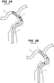
- the delivery sheath 2, with the stent 1 in its reduced undeployed configuration, may be introduced into the lumen of a blood vessel 9, and delivered to a target location within the blood vessel 9, as illustrated in Fig. 2A .
- the stent 1 may then be deployed out of the delivery sheath 2 via the stent delivery mechanism 3 by retracting the delivery sheath 2 in the proximal direction, and expanded to an enlarged configuration within the blood vessel 9 to support and reinforce the wall of the vessel 9, while maintaining the vessel 9 in an open, unobstructed condition, as illustrated in Fig. 2B .
- the stent 1 may be configured for being self-expanding, expanded by a stored potential radial force such as a balloon, or a combination of self-expanding and balloon-expanded.
- the other device may be a balloon catheter that is expanded within the deployed stent 1 to either expand the stent 1 into contact with the wall of the vessel 9 if the stent is not self-expanding, or if the stent is self-expanding, to ensure that the stent is an opposing engagement with the wall of the vessel 9.
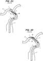
- the distal tip 5 of the delivery wire 4 may dig into the cells of the deployed stent 1, preventing reliable re-crossing of the deployed stent 1, especially when the stent 1 is deployed in a curvature of the vessel 9.
- the distal tip 3 of the delivery wire 4 is re-crossed over the deployed stent 1, it is desirable to re-cross the deployed stent 1 a sufficient amount, such that the more rigid portion of the delivery wire 3 resides within the deployed stent 1 to facilitate delivery of the balloon catheter into the deployed stent 1.
- the forward edges of the bumper 6a, 6b which are now exposed due to the removal of the stent 1, may catch on the struts of the stent 1, thereby creating additional challenges for re-crossing the deployed stent 1 a sufficient distance to allow the balloon catheter to be reliably guided into the deployed stent 1, as illustrated in Fig. 2D .
- EP 2532 324 an implant delivery system of the previously described kind has been disclosed, in which the implant is coaxially disposed between the delivery catheter and the elongate delivery mechanism that comprises a channel and a compressible annular bushing being a coil spring and and configured for being placed between a compressive profile and an expanded profile.
- the bushing does not assume an expanded profile. There edges may be formed that can hinder re-crossing of te deployed stent.
- an implant delivery system designed and configured as set forth in the attached claims.
- the implant delivery system 10 generally comprises an elongate delivery catheter 12, an elongate delivery mechanism 14, and a medical implant 16.
- the stent 16 is described as a stent, although in alternative embodiments, the medical implant can be any tubular implant that allows re-crossing via the elongated delivery mechanism 14, e.g., a flow diverter.
- the delivery catheter 12 can, e.g., take the form of a sheath, catheter, micro-catheter or the like.
- the implant delivery system 10 may be used in an "overthe-wire" configuration, wherein the delivery catheter 12 is introduced into the patient over a guidewire (not shown) that has been previously introduced, and the delivery catheter 12 extends over the entire length of the guidewire (not shown).
- the implant delivery system 10 may be used in a "rapid-exchange" configuration, where a guidewire (not shown) extends through only a distal portion of the delivery catheter 12 from a guidewire port (not shown).
- the implant delivery system 10 may be introduced into the patient after a guidewire had been withdrawn, leaving a sheath or access catheter distal portion at the target site for the implant delivery system 10 to navigate through the vasculature of the patient within the sheath or access catheter.
- the delivery catheter 12 may, e.g., comprise a length about 50cm-300cm, and typically about 60cm-200cm.
- the delivery catheter 12 is configured for accessing a body lumen, such as a blood vessel, for a desired treatment in a target site.
- a body lumen such as a blood vessel
- the target site may be within a small diameter blood vessel having a 2-5mm lumen diameter and accessible by way of a tortuous vessel path, which may involve shar vessel turns and multiple vessel branches.
- the delivery catheter 12 has a small suitable diameter and flexible construction.
- the delivery catheter 12 comprises an elongate sheath body 18 having a proximal portion 20 and a distal portion 22, and an inner lumen 24 extending between the proximal portion 20 and the distal portion 22 of the sheath body 18.
- the proximal portion 20 of the sheath body 18 remains outside of the patient and accessible to the operator when the implant delivery system 10 is in use, while the distal portion 22 of the sheath body 18 is sized and dimensioned to reach remote locations of a vasculature to deliver the stent 16 to a target location in a patient's body, such as an occlusion in a blood vessel, in a blood vessel adjacent to an aneurysm neck, a bifurcated blood vessel, or the like.
- the lumen 24 of the delivery catheter 12 is sized to accommodate longitudinal movement of the radially contracted implant 16 and elongate delivery mechanism 14.
- the delivery catheter 12 may have at least one fluid port 26 in fluid communication with the lumen 24 to introduce fluids into the delivery catheter 12 in order to hydrate the elongate delivery mechanism 14 and the stent 16.
- the delivery catheter 12 may include one or more optional marker bands (not shown) formed along the sheath body 18 from a radiopaque material that can be used to identify the location of the distal end of the delivery catheter 12 within the patient's vasculature system, or relative to the undeployed or deployed stent 16, using imaging technology (e.g., fluoroscope imaging).
- the delivery catheter 12 may include one or more, or a plurality of regions along its length having different configurations and/or characteristics.
- the distal portion 22 of the sheath body 18 may have an outer diameter less than the outer diameter of the proximal portion 20 to reduce the profile of the distal portion 22 and facilitate navigation in tortuous vasculature.
- the distal portion 22 may be more flexible than the proximal portion 20.
- the proximal portion 20 may be formed from material that is stiffer than the distal portion 22, so that the proximal portion 20 has sufficient pushability to advance through the patient's vascular system, while the distal portion 22 may be formed of a more flexible material so that the distal portion 22 may remain flexible and track more easily over a guidewire to access remote locations in tortuous regions of the vasculature.
- the proximal portion 20 may include a reinforcement layer, such a braided layer or coiled layer to enhance the pushability of the delivery catheter 12.
- the delivery catheter 12 may include a transition region between the proximal portion 20 and the distal portion 22.
- the sheath body 18 of the delivery catheter 12 may be composed of suitable polymeric materials, metals and/or alloys, such as polyethylene, stainless steel or other suitable biocompatible materials or combinations thereof.
- suitable metals and metal alloys can include stainless steel, such as 304V, 304L, and 316L stainless steel; nickel-titanium alloy such as a superelastic (i.e., pseudoelastic) or linear elastic nitinol; nickel-chromium alloy; nickel-chromium-iron alloy; cobalt alloy; tungsten or tungsten alloys; tantalum or tantalum alloys, gold or gold alloys, MP35-N (having a composition of about 35% Ni, 35% Co, 20% Cr, 9.75% Mo, a maximum 1% Fe, a maximum 1% Ti, a maximum 0.25% C, a maximum 0.15% Mn, and a maximum 0.15% Si); or the like; or other suitable metals, or combinations or alloys thereof.
- polystyrene resin examples include, but are not limited to, polyoxymethylene (POM), polybutylene terephthalate (PBT), polyether block ester, polyether block amide (PEBA), fluorinated ethylene propylene (FEP), polyethylene (PE), polypropylene (PP), polyvinylchloride (PVC), polyurethane, polytetrafluoroethylene (PTFE), polyether-ether ketone (PEEK), polyimide, polyamide, polyphenylene sulfide (PPS), polyphenylene oxide (PPO), polysufone, nylon, perfluoro(propyl vinyl ether) (PFA), polyether-ester, polymer/metal composites, or mixtures, blends or combinations thereof.
- POM polyoxymethylene
- PBT polybutylene terephthalate
- PEBA polyether block amide
- FEP fluorinated ethylene propylene
- PE polyethylene
- PP polypropylene
- PVC
- the sheath body 18 of the delivery catheter 12 may include a braidedshaft construction of stainless steel flat wire that is encapsulated or surrounded by a polymer coating.
- HYDROLENE is a polymer coating that may be used to cover the exterior portion of the sheath body 18.
- the system 10 is not limited to a particular construction or type of delivery catheter 12 and other constructions known to those skilled in the art may be used for the sheath body 18 of the delivery catheter 12.
- the lumen 24 of the delivery catheter 12 may be advantageously coated with a lubricious coating (not shown), such as PTFE, to reduce frictional forces between the sheath body 18 and the elongate delivery mechanism 14 and implant 16 when moved longitudinally within the lumen 24.
- the elongate delivery mechanism 14 is slidably disposed in the lumen 24 of the delivery catheter 12, and generally includes a delivery wire 28 having a proximal portion 30 and a distal portion 32.
- the delivery wire 28 may be composed of a conventional guidewire, torqueable cable tube, or a hypotube. In either case, there are numerous materials that can be used for the delivery wire 28 to achieve the desired properties that are commonly associated with medical devices. Some examples can include metals, metal alloys, polymers, metal-polymer composites, and the like, or any other suitable material.
- the delivery wire 28 may include nickel-titanium alloy, stainless steel, a composite of nickel-titanium alloy and stainless steel.
- the delivery wire 28 can be made of the same material along its length, or in some embodiments, can include portions or sections made of different materials.
- the material used to construct the delivery wire 28 is selected to impart varying flexibility and stiffness characteristics to different portions of the delivery wire 28.
- the proximal portion 30 and the distal portion 32 of the delivery wire 28 may be formed of different materials, for example materials having different moduli of elasticity, resulting in a difference in flexibility.
- the proximal portion 30 can be formed of stainless steel, and the distal portion 32 can be formed of a nickel-titanium alloy.
- any suitable material or combination of material may be used for the delivery wire 28, as desired.
- the delivery wire 28 is tapered from a relatively large diameter proximal portion 30 to a relatively small diameter distal portion 32.
- the elongate delivery mechanism 14 may further comprise a coil 34 affixed to the transition region of the delivery wire 28 between the proximal portion 30 and the distal portion 32, thereby maintaining lateral flexibility of the elongate delivery mechanism 14 distal to the proximal portion 30, while providing a uniform profile between the proximal portion 30 and the distal portion 32.
- the elongate delivery mechanism 14 may comprise an optional guidewire lumen (not shown).
- the elongate delivery mechanism 14 further comprises a proximal bumper 36a affixed to the distal end 30 of the delivery wire 28, and a distal bumper 36b affixed to the distal end 30 of the delivery wire 28 distal to the proximal bumper 36a, thereby creating an annular channel 38 between the proximal bumper 36a and the distal bumper 36b.
- the bumpers 36a, 36b may be composed of a suitable biocompatible material, such as stainless steel or nitinol.
- Each of the bumpers 36a, 36b is disk-shaped, and is sized to engage the lumen 24 of the delivery catheter 12.
- the outer surfaces of the bumpers 36a, 36b may impart low-fraction due to the material from which they are formed.
- the outer surfaces of the bumpers 36a, 36b may be coated with a lubricious coating, e.g., polytetrafluoroethylene (PTFE), hereby facilitating movement of the bumpers 36a, 36b through the lumen 24 of the delivery catheter 12.
- a lubricious coating e.g., polytetrafluoroethylene (PTFE)
- PTFE polytetrafluoroethylene
- the bumpers 36a, 36b, and thus, the annular channel 38 may have non-circular cross-sections, including irregular shapes.
- the elongate delivery mechanism 14 further comprises an annular bushing 40 disposed within the annular channel 38.
- the annular bushing 40 is configured for being placed between a compressive profile ( Fig. 5A ) and an expanded profile ( Fig.
- the annular bushing 40 may be composed of a suitable material, e.g., a polymeric material, or a non-polymeric material, such as super elastic material, which can be folded in the compressive profile and unfolded in the expanded profile.
- a suitable material e.g., a polymeric material, or a non-polymeric material, such as super elastic material, which can be folded in the compressive profile and unfolded in the expanded profile.
- the annular bushing 40 is not rotatably affixed within the annular channel 38, and is therefore free to spin within the annular channel 38.
- the elongate delivery mechanism 14 further comprises a coil 42 disposed about the distal end 30 of the delivery wire 28 distal to the distal bumper 36b, preferably in abutment with the distal surface of the distal bumper 36b.
- the coil 42 may be advantageously radiopaque to aid in visualization of the location and curvature of the distal tip 46 of the elongated delivery mechanism 14 during the re-crossing procedure, as discussed in further detail below.
- the coil 42 may be composed of a suitable biocompatible material, such as platinum, gold, tungsten, or alloys thereof or other metals.
- the elongate delivery mechanism 14 may comprise a material melted down and placed over the distal end 30 of the delivery wire 36 distal to the distal bumper 36b.
- the elongate delivery mechanism 14 may further comprise a polymer 44 that fills the spaces between the delivery wire 28 and coils 34, 42 to fully integrate the assembly into a unibody design.
- the elongate delivery mechanism 14 further comprises a distal tip 46 that is pre-shaped to assume a curved geometry (and in the preferred embodiment, J-shaped geometry) when unconstrained, and to assume a straight geometry (shown in phantom) when constrained.
- the distal tip 46 is affixed over the coil 42, although in alternative embodiments, the distal tip 46 may be formed from at least a portion of the delivery wire 28.
- the added thickness of the added distal tip 46 increases the diameter of the distal tip of the elongated delivery mechanism 14, as well as creates a bend, that facilitates re-crossing of the deployed stent 16.
- the stent 16 is coaxially disposed between the delivery catheter 12 and the elongate delivery mechanism 14.
- the elongate delivery mechanism 14 is configured for engaging the stent 16 when the elongate delivery mechanism 14 is axially translated relative to the delivery catheter 12 for delivery of the stent 16 into a target site of a patient.
- the interface between the elongate delivery mechanism 14 and the stent 16 will be described in further detail below.
- the stent 16 comprises a tubular resilient body 48 that constrains the distal tip 46 of the elongate delivery mechanism 14 to assume the straight geometry, and releases the constraining force from the distal tip 46 of the delivery mechanism 14 to allow the distal tip 46 of the delivery mechanism 14 to assume the curved geometry once the stent 16 is deployed from the delivery catheter 12.
- the stent 16 has a proximal portion 50, a distal portion 52, and an inner lumen 54 extending through the tubular body 48 between the proximal portion 50 and the distal portion 52.
- the stent 16 has a delivery configuration when radially constrained within the lumen 24 of the delivery catheter 12, as illustrated in Fig. 3 .
- the cross-sectional dimension of the tubular resilient body 48, when the stent 16 is in the delivery configuration, is the same as cross-sectional dimensions of the bumpers 36a, 36b to facilitate displacement of the elongated delivery mechanism 14 and implant 16 within the delivery catheter 12.
- the tubular body 48 of the stent 16 comprises a plurality struts 56 that form cells 58 therebetween, and is biased to expand radially outwards into a deployed configuration when deployed out of the delivery catheter 12.
- the stent 16 may be constructed of any number of various materials commonly associated with medical devices, including metals, metal alloys, polymers, metal-polymer composites, etc., e.g., stainless steels, cobalt-based alloys, gold alloys, elgioloy, nickel, titanium, platinum, nitinol, shape memory polymers, or combinations thereof.
- the stent 16 may also be formed in a variety of manners as well.
- the stent 16 may be formed by etching or cutting a pattern from a tube or sheet of stent material; a sheet of stent material may be cut or etched according to a desired stent pattern whereupon the sheet may be rolled or otherwise formed into the desired substantially tubular, bifurcated or other shape.
- a sheet of stent material may be cut or etched according to a desired stent pattern whereupon the sheet may be rolled or otherwise formed into the desired substantially tubular, bifurcated or other shape.
- one or more wires or ribbons of stent material may be woven, braided or otherwise formed into a desired shape and pattern.
- the stent 16 may include further components that are welded, bonded or otherwise engaged to one another.
- the stent 16 may include a non-porous, non-permeable biocompatible material, cover or the like, when the stent 16 is used as a blood flow diverter.
- Implants 16 such as stents, are further described in U.S. Patent Application Ser. No. 14/139,815, entitled “Multilayer Stent,” filed December 23, 2013 , and U.S. Patent Application Ser. No. 14/104,906, entitled “Stent Delivery System,” filed December 12, 2013 .
- the stent 16 further comprises at least one proximal radiopaque marker 60a (in this case, three) formed at a proximal portion 50 of the tubular body 48, and at least one distal radiopaque marker 60b (in this case, three not shown in Fig. 7 ) formed at a distal portion 52 of the tubular body 48.
- the radiopaque markers 60a, 60b be composed of a suitable biocompatible material, such as platinum, gold, tungsten, or alloys thereof or other metals.
- the radiopaque markers 60a, 60b allow the stent 16 to be visualized during its delivery to the target location in the vessel.
- the proximal marker 60a indicates a location of the proximal end of the stent 16
- the distal marker 60b indicates a location of the distal end of the stent 16.
- the proximal radiopaque marker 60a serves as an engagement element that is releasably engaged with the annular channel 38 of the elongate delivery mechanism 14.
- each of the engagement elements 60a takes the form of a resilient angled arm that catches the annular channel 38 of the elongate delivery mechanism 14.
- the resilient angled arms 60a of the stent 16 are biased to be radially displaced in the outward radial direction.
- the lumen 24 of the delivery catheter 12 is sized to maintain the angled arms 60a within the annular channel 38 of the elongated delivery mechanism 14, and to urge the annular bushing 40 into the compressive profile (as shown in Fig. 5a ), such that the elongate delivery mechanism 14 and the stent 16 can be distally displaced in the lumen 24 of the delivery catheter 12 in unison to deploy the stent 16 from the delivery catheter 12.
- the resilient angled arms 60a will displace in the radial outward direction, thereby disengaging, thereby releasing the stent 16.
- the annular bushing 40 will assume the expanded profile (as illustrated in Fig.
- the annular bushing 40 is preferably shaped to occupy the annular channel 38 as much as possible while accommodating the proximal radiopaque marker 60a.
- engagement elements 60a have been described as radiopaque angled arms, it should be appreciated that, in alternative embodiments, the engagement elements 60a may not be radiopaque, and may take other forms besides angled arms that are otherwise capable of engaging the annular channel 38 and placing the annular bushing 40 in its compressed profile.
- An exemplary method 100 of using the implant delivery system 10 (illustrated in Fig. 8 ) will now be described in order to better understand the structure and features of the implant delivery system 10.
- the method 100 of using the implant delivery system 10 will be described in the context of treating a blockage at a target site of a blood vessel within the vasculature of a patient, and assumes that the blockage has been previously removed from the blood vessel.
- the elongated delivery mechanism 14 and implant 16 (in this case a stent) is front-loaded into the delivery catheter 12, e.g., by introducing into the proximal end of the delivery catheter 12, and subsequently advancing, the elongated delivery mechanism 14 and implant 16 within the lumen 24 of the delivery catheter 12 until the stent 16 is located at the distal end of the delivery catheter 12 (step 102) (see Fig. 3 ).
- This step can be performed by the manufacturer or medical personnel.
- the stent 16 and bumpers 36a, 36b of the elongated delivery mechanism 14 may be threaded into the proximal end of the delivery catheter 12 using an iris crimper (available from Machine Solutions, Inc.) or a funnel, until the stent 16 is located at the distal end of the delivery catheter 12. At this point, the stent 16 is affixed to the elongate delivery mechanism 14, such that the distal tip 46 of the elongate delivery mechanism 14 is constrained by the stent 16, and therefore, assumes its straight profile (see Fig.
- the engagement elements 52 i.e., the angled arms
- the stent 16 are disposed within the annular channel 38 of the elongate delivery mechanism 14, such that the annular bushing 40 assumes its compressed profile (see Fig. 5A ).
- the hydrating liquid such as normal saline
- the hydrating liquid is introduced into the liquid port at the proximal end 20 of the sheath body 18 of the delivery catheter 12, and travels through the lumen 24 of the sheath body 18 to hydrate the stent 16 (step 104).
- the distal end of the implant delivery system 10 is introduced into the vasculature of a patient in a conventional manner, and advanced through the vasculature (e.g., over a previously placed guidewire) until the distal portion 20 of the delivery catheter 12 is adjacent a target site within a blood vessel 9 of the patient (step 106) (see Fig. 9A ).
- the radiopaque markers (not shown) on the distal portion 20 of the sheath body 18 may aid in visualizing the delivery catheter relevant to anatomical landmarks as the delivery catheter 12 is guided through the vasculature.
- the implant delivery system 10 may be introduced into the vasculature of the patient in unison, in which case, the elongated delivery mechanism 14 and stent 16 may first be loaded into the delivery catheter 12, as discussed above with respect to step 102, or delivery catheter 12, without the elongated delivery mechanism 14 and stent 16, can first be introduced into the vasculature of the patient and advanced to the target site of the blood vessel, and then the elongated delivery mechanism 14 and stent 16 can then be loaded into the delivery catheter 12 in the manner described above with respect to step 102.
- the delivery catheter 12 and elongate delivery mechanism 14 are axially translated relative to each other (e.g., by pulling the delivery catheter 12 in the proximal direction, by pushing the elongate delivery mechanism 14 in the distal direction, or both), thereby distally advancing implant 16 (in this case, a stent) within the lumen 24 of the delivery catheter 12 until the stent 16 deploys out of the lumen 24 of the delivery catheter 12 at the target site of the blood vessel 9 (step 108) (see Fig. 9B ).
- implant 16 in this case, a stent
- the resiliency of the engagement elements 60a (i.e., the angled arms) of the stent 16 cause them to radially move outward from the annular channel 38 between the bumpers 36a, 36b, releasing the stent 16 from the elongate delivery mechanism 14, which allows the annular bushing 40 of the elongate delivery mechanism 14 to assume the expanded profile (step 110), and the distal tip 46 of the elongate delivery mechanism 14 to assume its curved geometry (in this case, a J-shape) (step 112) (see Fig. 9B ).
- the expanded annular bushing 40 substantially occupies the entirety of the annular channel 38 (see Fig. 5B ), and the distal tip 46 curves back on itself, thereby eliminating any edges and low-profile mechanisms that may hinder re-crossing of deployed stent 16 by the elongate delivery mechanism 14.
- the radiopaque markers of the stent 18 (in this case, the proximal and distal markers 60a, 60b) allow visualization of the stent 18 relative to the delivery catheter 12 and other anatomical features adjacent the target site.
- the deployed stent 16 is re-crossed with the distal end of the elongate delivery mechanism 14 until distal tip 46 and annular channel 38 are distal to the deployed stent 16 (step 116) (see Fig. 9C ).
- the combination of the increased diameter and J-shape of the distal tip 46 of the elongated delivery mechanism 14, as well as the expansion of the annular bushing 40 within the annular channel 38 between the bumpers 36a, 36b of the elongated delivery mechanism 14, avoids or at least minimizes the possibility that the elongated delivery mechanism 14 will catch or snag on the struts of the stent 16 during the re-crossing procedure.
- the radiopaque marker at the distal end of the elongate delivery mechanism 14 (in this case, the coil 42 disposed at the distal portion 32 of the delivery wire 28), allows visualization of the location and shape of the distal tip 46 relative to the stent 16 during the stent re-crossing procedure.
- the delivery catheter 12 is removed from the elongate delivery mechanism 14 (see Fig. 9D ), ultimately being entirely removed from the patient (step 118).
- the delivery catheter 12 may be removed prior to or subsequent to the stent re-crossing procedure.
- Another catheter 70 (in this case, a balloon catheter) is guided over the elongate delivery mechanism 14, while the distal tip 46 and annular channel 38 are distal to the deployed stent 16, until an operative element 72 (in this case, a balloon) of the balloon catheter 70 is adjacent to the target site (in this case, inside of the deployed stent 16) (step 120) (see Fig. 9E ).
- the balloon catheter 70 is then operated, and in particular, the balloon 72 is inflated to radially urge the deployed stent 16 against the wall of the vessel in order to support and reinforce the wall of the vessel, while maintaining the vessel in an open, unobstructed condition (step 122) (see Fig. 9F ).
- the balloon 72 is then deflated, and the elongate delivery mechanism 14 and balloon catheter 70 are removed from the patient (step 124).
Landscapes
- Health & Medical Sciences (AREA)
- Engineering & Computer Science (AREA)
- Biomedical Technology (AREA)
- Cardiology (AREA)
- Oral & Maxillofacial Surgery (AREA)
- Transplantation (AREA)
- Heart & Thoracic Surgery (AREA)
- Vascular Medicine (AREA)
- Life Sciences & Earth Sciences (AREA)
- Animal Behavior & Ethology (AREA)
- General Health & Medical Sciences (AREA)
- Public Health (AREA)
- Veterinary Medicine (AREA)
- Media Introduction/Drainage Providing Device (AREA)
Description
- The present disclosure relates generally to medical devices and intravascular medical procedures and, more particularly, to devices for delivering an implant to a target site in a blood or other body vessel.
- The use of intravascular medical devices has become an effective method for treating many types of vascular disease. In general, a suitable intravascular device is inserted into the vascular system of the patient and navigated through the vasculature to a desired target site. Using this method, virtually any target site in the patient's vascular system may be accessed, including the coronary, cerebral, and peripheral vasculature.
- Medical implants, such as stents, stent grafts, flow-diverters, and vena cava filters, are often utilized in combination with a delivery device for placement at a desired location within the body. For example, with reference to
Fig. 1 , amedical implant 1, such as a stent, may be loaded into adelivery sheath 2 via astent delivery mechanism 3. Thestent delivery mechanism 3 comprises adelivery wire 4 having adistal tip 5 on which thestent 1 is affixed. Thestent delivery mechanism 3 further comprises aproximal bumper 6a and adistal bumper 6b between which there is formed an annular channel 7 for engaging thestent 1 in a manner that allows thestent 1 to be axially displaced within thedelivery sheath 2, while releasing thestent 1 once it is deployed outside of, and therefore no longer contained by, thedelivery sheath 2. In this embodiment, thestent 1 includes one or more proximalradiopaque marker 8a (two shown) and one or more distalradiopaque markers 8b (two shown). The proximalradiopaque markers 8a reside within the annular channel 7 between thebumpers stent 1 and thestent delivery mechanism 3. - The
delivery sheath 2, with thestent 1 in its reduced undeployed configuration, may be introduced into the lumen of ablood vessel 9, and delivered to a target location within theblood vessel 9, as illustrated inFig. 2A . Once delivered to a target location within the body, thestent 1 may then be deployed out of thedelivery sheath 2 via thestent delivery mechanism 3 by retracting thedelivery sheath 2 in the proximal direction, and expanded to an enlarged configuration within theblood vessel 9 to support and reinforce the wall of thevessel 9, while maintaining thevessel 9 in an open, unobstructed condition, as illustrated inFig. 2B . Thestent 1 may be configured for being self-expanding, expanded by a stored potential radial force such as a balloon, or a combination of self-expanding and balloon-expanded. - Oftentimes, it is desirable to remove the
delivery sheath 2 from the patient while thestent delivery mechanism 3 remains in the patient, re-cross the deployedstent 1 with thestent delivery mechanism 3, and guide another device (not shown) over thestent delivery mechanism 3 into engagement with the deployedstent 1. For example, the other device may be a balloon catheter that is expanded within the deployedstent 1 to either expand thestent 1 into contact with the wall of thevessel 9 if the stent is not self-expanding, or if the stent is self-expanding, to ensure that the stent is an opposing engagement with the wall of thevessel 9. - However, crossing the deployed
stent 1 with adelivery wire 3 poses challenges due to mechanical interactions between adistal tip 5 andbumpers stent delivery mechanism 3 and the struts of the deployedstent 1. As one example illustrated inFig. 2C , thedistal tip 5 of thedelivery wire 4 may dig into the cells of the deployedstent 1, preventing reliable re-crossing of the deployedstent 1, especially when thestent 1 is deployed in a curvature of thevessel 9. Even if thedistal tip 3 of thedelivery wire 4 is re-crossed over the deployedstent 1, it is desirable to re-cross the deployed stent 1 a sufficient amount, such that the more rigid portion of thedelivery wire 3 resides within the deployedstent 1 to facilitate delivery of the balloon catheter into the deployedstent 1. However, the forward edges of thebumper stent 1, may catch on the struts of thestent 1, thereby creating additional challenges for re-crossing the deployed stent 1 a sufficient distance to allow the balloon catheter to be reliably guided into the deployedstent 1, as illustrated inFig. 2D . - In
EP 2532 324 an implant delivery system of the previously described kind has been disclosed, in which the implant is coaxially disposed between the delivery catheter and the elongate delivery mechanism that comprises a channel and a compressible annular bushing being a coil spring and and configured for being placed between a compressive profile and an expanded profile. When the stent has been released, the bushing does not assume an expanded profile. There edges may be formed that can hinder re-crossing of te deployed stent. - In accordance with the disclosed invention, an implant delivery system is provided designed and configured as set forth in the attached claims.
- Other and further aspects and features of embodiments of the disclosed inventions will become apparent from the ensuing detailed description in view of the accompanying figures.
- The drawings illustrate the design and utility of exemplary embodiments of the disclosed inventions, in which similar elements are referred to by common reference numerals. It should be noted that the figures are not drawn to scale and that elements of similar structures or functions are represented by like reference numerals throughout the figures. It should also be noted that the figures are only intended to facilitate the detailed description of the embodiments, and are not intended as an exhaustive description thereof or as a limitation on the scope of the disclosed invention,
which is defined only by the appended claims. - In addition, various claimed embodiments of the disclosed inventions need not have all the aspects or advantages depicted in the drawings. An aspect or an advantage described in conjunction with a particular embodiment is not necessarily limited to that embodiment and may be practiced in other embodiments, even if not so illustrated. Understanding that these drawings depict only typical embodiments of the disclosed invention and are not therefore to be considered limiting of its scope, the disclosed invention will be described and explained with additional specificity and detail through the use of the accompanying drawings in which:
-
Fig. 1 is a cross-sectional view of a prior art implant delivery system; -
Figs. 2A-2D are plan views illustrating a prior art method using the implant delivery system ofFig. 1 to deploy a stent within the vasculature of a patient; -
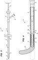
Fig. 3 is a side view of an implant delivery system constructed in accordance with one embodiment of the disclosed inventions; -
Fig. 4 is a cross-sectional view of one embodiment of an elongate delivery mechanism used in the implant delivery system ofFig. 3 ; -
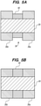
Fig. 5A is a cross-sectional view of one embodiment of a compliant annular bushing used in the elongate delivery mechanism ofFig. 4 to occupy an annular space, particularly showing the annular bushing in a compressed profile; -
Fig. 5B is a cross-sectional view of the compliant annular ofFig. 5A , particularly shown in an expanded profile; -
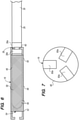
Fig. 6 is a side view of the distal end of the elongate delivery mechanism ofFig. 4 , particularly showing an undeployed stent affixed thereto; -
Fig. 7 is an axial view of the stent ofFig. 6 , particularly showing the engagement elements of the stent; -
Fig. 8 is a flow diagram illustrating an exemplary method of operating the implant delivery system ofFig. 3 to implant a stent within the vasculature of a patient; and -
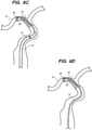
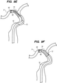
Figs. 9A-9F are plan views illustrating the method ofFig. 8 . - Referring first to
Fig. 3 , one embodiment of animplant delivery system 10 constructed in accordance with one embodiment of the disclosed invention will be described. Theimplant delivery system 10 generally comprises anelongate delivery catheter 12, anelongate delivery mechanism 14, and amedical implant 16. In the illustrated embodiment, thestent 16 is described as a stent, although in alternative embodiments, the medical implant can be any tubular implant that allows re-crossing via theelongated delivery mechanism 14, e.g., a flow diverter. - The
delivery catheter 12 can, e.g., take the form of a sheath, catheter, micro-catheter or the like. Theimplant delivery system 10 may be used in an "overthe-wire" configuration, wherein thedelivery catheter 12 is introduced into the patient over a guidewire (not shown) that has been previously introduced, and thedelivery catheter 12 extends over the entire length of the guidewire (not shown). Alternatively, theimplant delivery system 10 may be used in a "rapid-exchange" configuration, where a guidewire (not shown) extends through only a distal portion of thedelivery catheter 12 from a guidewire port (not shown). In other alternative embodiments, theimplant delivery system 10 may be introduced into the patient after a guidewire had been withdrawn, leaving a sheath or access catheter distal portion at the target site for theimplant delivery system 10 to navigate through the vasculature of the patient within the sheath or access catheter. - The
delivery catheter 12 may, e.g., comprise a length about 50cm-300cm, and typically about 60cm-200cm. Thedelivery catheter 12 is configured for accessing a body lumen, such as a blood vessel, for a desired treatment in a target site. For example, the target site may be within a small diameter blood vessel having a 2-5mm lumen diameter and accessible by way of a tortuous vessel path, which may involve shar vessel turns and multiple vessel branches. In such cases, thedelivery catheter 12 has a small suitable diameter and flexible construction. - In any event, the
delivery catheter 12 comprises anelongate sheath body 18 having aproximal portion 20 and adistal portion 22, and aninner lumen 24 extending between theproximal portion 20 and thedistal portion 22 of thesheath body 18. Theproximal portion 20 of thesheath body 18 remains outside of the patient and accessible to the operator when theimplant delivery system 10 is in use, while thedistal portion 22 of thesheath body 18 is sized and dimensioned to reach remote locations of a vasculature to deliver thestent 16 to a target location in a patient's body, such as an occlusion in a blood vessel, in a blood vessel adjacent to an aneurysm neck, a bifurcated blood vessel, or the like. Thelumen 24 of thedelivery catheter 12 is sized to accommodate longitudinal movement of the radially contractedimplant 16 andelongate delivery mechanism 14. - The
delivery catheter 12 may have at least onefluid port 26 in fluid communication with thelumen 24 to introduce fluids into thedelivery catheter 12 in order to hydrate theelongate delivery mechanism 14 and thestent 16. Thedelivery catheter 12 may include one or more optional marker bands (not shown) formed along thesheath body 18 from a radiopaque material that can be used to identify the location of the distal end of thedelivery catheter 12 within the patient's vasculature system, or relative to the undeployed or deployedstent 16, using imaging technology (e.g., fluoroscope imaging). - The
delivery catheter 12 may include one or more, or a plurality of regions along its length having different configurations and/or characteristics. For example, thedistal portion 22 of thesheath body 18 may have an outer diameter less than the outer diameter of theproximal portion 20 to reduce the profile of thedistal portion 22 and facilitate navigation in tortuous vasculature. Furthermore, thedistal portion 22 may be more flexible than theproximal portion 20. Generally, theproximal portion 20 may be formed from material that is stiffer than thedistal portion 22, so that theproximal portion 20 has sufficient pushability to advance through the patient's vascular system, while thedistal portion 22 may be formed of a more flexible material so that thedistal portion 22 may remain flexible and track more easily over a guidewire to access remote locations in tortuous regions of the vasculature. In some instances, theproximal portion 20 may include a reinforcement layer, such a braided layer or coiled layer to enhance the pushability of thedelivery catheter 12. Thedelivery catheter 12 may include a transition region between theproximal portion 20 and thedistal portion 22. - The
sheath body 18 of thedelivery catheter 12 may be composed of suitable polymeric materials, metals and/or alloys, such as polyethylene, stainless steel or other suitable biocompatible materials or combinations thereof. Examples of suitable metals and metal alloys can include stainless steel, such as 304V, 304L, and 316L stainless steel; nickel-titanium alloy such as a superelastic (i.e., pseudoelastic) or linear elastic nitinol; nickel-chromium alloy; nickel-chromium-iron alloy; cobalt alloy; tungsten or tungsten alloys; tantalum or tantalum alloys, gold or gold alloys, MP35-N (having a composition of about 35% Ni, 35% Co, 20% Cr, 9.75% Mo, a maximum 1% Fe, a maximum 1% Ti, a maximum 0.25% C, a maximum 0.15% Mn, and a maximum 0.15% Si); or the like; or other suitable metals, or combinations or alloys thereof. Examples of some suitable polymers can include, but are not limited to, polyoxymethylene (POM), polybutylene terephthalate (PBT), polyether block ester, polyether block amide (PEBA), fluorinated ethylene propylene (FEP), polyethylene (PE), polypropylene (PP), polyvinylchloride (PVC), polyurethane, polytetrafluoroethylene (PTFE), polyether-ether ketone (PEEK), polyimide, polyamide, polyphenylene sulfide (PPS), polyphenylene oxide (PPO), polysufone, nylon, perfluoro(propyl vinyl ether) (PFA), polyether-ester, polymer/metal composites, or mixtures, blends or combinations thereof. - The
sheath body 18 of thedelivery catheter 12 may include a braidedshaft construction of stainless steel flat wire that is encapsulated or surrounded by a polymer coating. By way of non-limiting example, HYDROLENE is a polymer coating that may be used to cover the exterior portion of thesheath body 18. Of course, thesystem 10 is not limited to a particular construction or type ofdelivery catheter 12 and other constructions known to those skilled in the art may be used for thesheath body 18 of thedelivery catheter 12. Thelumen 24 of thedelivery catheter 12 may be advantageously coated with a lubricious coating (not shown), such as PTFE, to reduce frictional forces between thesheath body 18 and theelongate delivery mechanism 14 andimplant 16 when moved longitudinally within thelumen 24. - The
elongate delivery mechanism 14 is slidably disposed in thelumen 24 of thedelivery catheter 12, and generally includes adelivery wire 28 having aproximal portion 30 and adistal portion 32. Thedelivery wire 28 may be composed of a conventional guidewire, torqueable cable tube, or a hypotube. In either case, there are numerous materials that can be used for thedelivery wire 28 to achieve the desired properties that are commonly associated with medical devices. Some examples can include metals, metal alloys, polymers, metal-polymer composites, and the like, or any other suitable material. - For example, the
delivery wire 28 may include nickel-titanium alloy, stainless steel, a composite of nickel-titanium alloy and stainless steel. In some cases, thedelivery wire 28 can be made of the same material along its length, or in some embodiments, can include portions or sections made of different materials. In some embodiments, the material used to construct thedelivery wire 28 is selected to impart varying flexibility and stiffness characteristics to different portions of thedelivery wire 28. For example, theproximal portion 30 and thedistal portion 32 of thedelivery wire 28 may be formed of different materials, for example materials having different moduli of elasticity, resulting in a difference in flexibility. For example, theproximal portion 30 can be formed of stainless steel, and thedistal portion 32 can be formed of a nickel-titanium alloy. However, any suitable material or combination of material may be used for thedelivery wire 28, as desired. - Referring now to
Fig. 4 , to increase the flexibility of the distal end of thedelivery wire 28, thedelivery wire 28 is tapered from a relatively large diameterproximal portion 30 to a relatively small diameterdistal portion 32. In this case, theelongate delivery mechanism 14 may further comprise acoil 34 affixed to the transition region of thedelivery wire 28 between theproximal portion 30 and thedistal portion 32, thereby maintaining lateral flexibility of theelongate delivery mechanism 14 distal to theproximal portion 30, while providing a uniform profile between theproximal portion 30 and thedistal portion 32. Theelongate delivery mechanism 14 may comprise an optional guidewire lumen (not shown). - The
elongate delivery mechanism 14 further comprises aproximal bumper 36a affixed to thedistal end 30 of thedelivery wire 28, and adistal bumper 36b affixed to thedistal end 30 of thedelivery wire 28 distal to theproximal bumper 36a, thereby creating anannular channel 38 between theproximal bumper 36a and thedistal bumper 36b. Thebumpers bumpers lumen 24 of thedelivery catheter 12. The outer surfaces of thebumpers bumpers bumpers lumen 24 of thedelivery catheter 12. Although thebumpers annular channel 38, preferably have a circular cross-section, thebumpers annular channel 38, may have non-circular cross-sections, including irregular shapes. Significantly, theelongate delivery mechanism 14 further comprises anannular bushing 40 disposed within theannular channel 38. Theannular bushing 40 is configured for being placed between a compressive profile (Fig. 5A ) and an expanded profile (Fig. 5B ), as will be discussed in further detail below. Theannular bushing 40 may be composed of a suitable material, e.g., a polymeric material, or a non-polymeric material, such as super elastic material, which can be folded in the compressive profile and unfolded in the expanded profile. Preferably, theannular bushing 40 is not rotatably affixed within theannular channel 38, and is therefore free to spin within theannular channel 38. - The
elongate delivery mechanism 14 further comprises acoil 42 disposed about thedistal end 30 of thedelivery wire 28 distal to thedistal bumper 36b, preferably in abutment with the distal surface of thedistal bumper 36b. Thecoil 42 may be advantageously radiopaque to aid in visualization of the location and curvature of thedistal tip 46 of theelongated delivery mechanism 14 during the re-crossing procedure, as discussed in further detail below. In this case, thecoil 42 may be composed of a suitable biocompatible material, such as platinum, gold, tungsten, or alloys thereof or other metals. Alternatively, instead of acoil 42, theelongate delivery mechanism 14 may comprise a material melted down and placed over thedistal end 30 of the delivery wire 36 distal to thedistal bumper 36b. Theelongate delivery mechanism 14 may further comprise apolymer 44 that fills the spaces between thedelivery wire 28 and coils 34, 42 to fully integrate the assembly into a unibody design. - Significantly, the
elongate delivery mechanism 14 further comprises adistal tip 46 that is pre-shaped to assume a curved geometry (and in the preferred embodiment, J-shaped geometry) when unconstrained, and to assume a straight geometry (shown in phantom) when constrained. In the illustrated embodiment, thedistal tip 46 is affixed over thecoil 42, although in alternative embodiments, thedistal tip 46 may be formed from at least a portion of thedelivery wire 28. As will also be discussed in further detail below, the added thickness of the addeddistal tip 46 increases the diameter of the distal tip of theelongated delivery mechanism 14, as well as creates a bend, that facilitates re-crossing of the deployedstent 16. - As illustrated in
Fig. 3 , thestent 16 is coaxially disposed between thedelivery catheter 12 and theelongate delivery mechanism 14. Theelongate delivery mechanism 14 is configured for engaging thestent 16 when theelongate delivery mechanism 14 is axially translated relative to thedelivery catheter 12 for delivery of thestent 16 into a target site of a patient. The interface between theelongate delivery mechanism 14 and thestent 16 will be described in further detail below. - Referring to
Fig. 6 , thestent 16 comprises a tubularresilient body 48 that constrains thedistal tip 46 of theelongate delivery mechanism 14 to assume the straight geometry, and releases the constraining force from thedistal tip 46 of thedelivery mechanism 14 to allow thedistal tip 46 of thedelivery mechanism 14 to assume the curved geometry once thestent 16 is deployed from thedelivery catheter 12. Thestent 16 has aproximal portion 50, adistal portion 52, and aninner lumen 54 extending through thetubular body 48 between theproximal portion 50 and thedistal portion 52. Thestent 16 has a delivery configuration when radially constrained within thelumen 24 of thedelivery catheter 12, as illustrated inFig. 3 . Preferably, the cross-sectional dimension of the tubularresilient body 48, when thestent 16 is in the delivery configuration, is the same as cross-sectional dimensions of thebumpers elongated delivery mechanism 14 andimplant 16 within thedelivery catheter 12. - The
tubular body 48 of thestent 16 comprises a plurality struts 56 that formcells 58 therebetween, and is biased to expand radially outwards into a deployed configuration when deployed out of thedelivery catheter 12. Thestent 16 may be constructed of any number of various materials commonly associated with medical devices, including metals, metal alloys, polymers, metal-polymer composites, etc., e.g., stainless steels, cobalt-based alloys, gold alloys, elgioloy, nickel, titanium, platinum, nitinol, shape memory polymers, or combinations thereof. Thestent 16 may also be formed in a variety of manners as well. For example, thestent 16 may be formed by etching or cutting a pattern from a tube or sheet of stent material; a sheet of stent material may be cut or etched according to a desired stent pattern whereupon the sheet may be rolled or otherwise formed into the desired substantially tubular, bifurcated or other shape. For thestent 16, one or more wires or ribbons of stent material may be woven, braided or otherwise formed into a desired shape and pattern. Thestent 16 may include further components that are welded, bonded or otherwise engaged to one another. Thestent 16 may include a non-porous, non-permeable biocompatible material, cover or the like, when thestent 16 is used as a blood flow diverter.Implants 16, such as stents, are further described inU.S. Patent Application Ser. No. 14/139,815, entitled "Multilayer Stent," filed December 23, 2013 U.S. Patent Application Ser. No. 14/104,906, entitled "Stent Delivery System," filed December 12, 2013 - Referring further to
Fig. 7 , thestent 16 further comprises at least one proximalradiopaque marker 60a (in this case, three) formed at aproximal portion 50 of thetubular body 48, and at least one distal radiopaque marker 60b (in this case, three not shown inFig. 7 ) formed at adistal portion 52 of thetubular body 48. Theradiopaque markers 60a, 60b be composed of a suitable biocompatible material, such as platinum, gold, tungsten, or alloys thereof or other metals. Theradiopaque markers 60a, 60b allow thestent 16 to be visualized during its delivery to the target location in the vessel. That is, theproximal marker 60a indicates a location of the proximal end of thestent 16, whereas the distal marker 60b indicates a location of the distal end of thestent 16. Significantly, the proximalradiopaque marker 60a serves as an engagement element that is releasably engaged with theannular channel 38 of theelongate delivery mechanism 14. In the illustrated embodiment, each of theengagement elements 60a takes the form of a resilient angled arm that catches theannular channel 38 of theelongate delivery mechanism 14. - The resilient
angled arms 60a of thestent 16 are biased to be radially displaced in the outward radial direction. However, thelumen 24 of thedelivery catheter 12 is sized to maintain theangled arms 60a within theannular channel 38 of theelongated delivery mechanism 14, and to urge theannular bushing 40 into the compressive profile (as shown inFig. 5a ), such that theelongate delivery mechanism 14 and thestent 16 can be distally displaced in thelumen 24 of thedelivery catheter 12 in unison to deploy thestent 16 from thedelivery catheter 12. Once thestent 16 is deployed from thelumen 24 of thedelivery catheter 12, the resilientangled arms 60a will displace in the radial outward direction, thereby disengaging, thereby releasing thestent 16. As will be described in further detail below, theannular bushing 40 will assume the expanded profile (as illustrated inFig. 5b ) after thestent 16 is deployed from thedelivery catheter 12, substantially occupying the entirety of the annular channel 38 (i.e., at least 90 percent of theannular channel 38 is although optimally, the outer surface of theannular bushing 40 is completely flush with the outer surfaces of thebumpers annular channel 38 that may snag on the deployedstent 16 during a re-crossing process, as will be described in further detail below. Thus, theannular bushing 40 is preferably shaped to occupy theannular channel 38 as much as possible while accommodating the proximalradiopaque marker 60a. - Although the
engagement elements 60a have been described as radiopaque angled arms, it should be appreciated that, in alternative embodiments, theengagement elements 60a may not be radiopaque, and may take other forms besides angled arms that are otherwise capable of engaging theannular channel 38 and placing theannular bushing 40 in its compressed profile. - An
exemplary method 100 of using the implant delivery system 10 (illustrated inFig. 8 ) will now be described in order to better understand the structure and features of theimplant delivery system 10. Themethod 100 of using theimplant delivery system 10 will be described in the context of treating a blockage at a target site of a blood vessel within the vasculature of a patient, and assumes that the blockage has been previously removed from the blood vessel. - First, the
elongated delivery mechanism 14 and implant 16 (in this case a stent) is front-loaded into thedelivery catheter 12, e.g., by introducing into the proximal end of thedelivery catheter 12, and subsequently advancing, theelongated delivery mechanism 14 andimplant 16 within thelumen 24 of thedelivery catheter 12 until thestent 16 is located at the distal end of the delivery catheter 12 (step 102) (seeFig. 3 ). This step can be performed by the manufacturer or medical personnel. Thestent 16 andbumpers elongated delivery mechanism 14 may be threaded into the proximal end of thedelivery catheter 12 using an iris crimper (available from Machine Solutions, Inc.) or a funnel, until thestent 16 is located at the distal end of thedelivery catheter 12. At this point, thestent 16 is affixed to theelongate delivery mechanism 14, such that thedistal tip 46 of theelongate delivery mechanism 14 is constrained by thestent 16, and therefore, assumes its straight profile (seeFig. 4 ), and the engagement elements 52 (i.e., the angled arms) of thestent 16 are disposed within theannular channel 38 of theelongate delivery mechanism 14, such that theannular bushing 40 assumes its compressed profile (seeFig. 5A ). - Next, the hydrating liquid, such as normal saline, is introduced into the liquid port at the
proximal end 20 of thesheath body 18 of thedelivery catheter 12, and travels through thelumen 24 of thesheath body 18 to hydrate the stent 16 (step 104). Next, the distal end of theimplant delivery system 10 is introduced into the vasculature of a patient in a conventional manner, and advanced through the vasculature (e.g., over a previously placed guidewire) until thedistal portion 20 of thedelivery catheter 12 is adjacent a target site within ablood vessel 9 of the patient (step 106) (seeFig. 9A ). The radiopaque markers (not shown) on thedistal portion 20 of thesheath body 18 may aid in visualizing the delivery catheter relevant to anatomical landmarks as thedelivery catheter 12 is guided through the vasculature. Theimplant delivery system 10 may be introduced into the vasculature of the patient in unison, in which case, theelongated delivery mechanism 14 andstent 16 may first be loaded into thedelivery catheter 12, as discussed above with respect to step 102, ordelivery catheter 12, without theelongated delivery mechanism 14 andstent 16, can first be introduced into the vasculature of the patient and advanced to the target site of the blood vessel, and then theelongated delivery mechanism 14 andstent 16 can then be loaded into thedelivery catheter 12 in the manner described above with respect to step 102. - Next, the
delivery catheter 12 andelongate delivery mechanism 14 are axially translated relative to each other (e.g., by pulling thedelivery catheter 12 in the proximal direction, by pushing theelongate delivery mechanism 14 in the distal direction, or both), thereby distally advancing implant 16 (in this case, a stent) within thelumen 24 of thedelivery catheter 12 until thestent 16 deploys out of thelumen 24 of thedelivery catheter 12 at the target site of the blood vessel 9 (step 108) (seeFig. 9B ). As a result of the deployment of thestent 16, and thus, the release of the compressive force by thedelivery catheter 12 on the distal end of theelongate delivery mechanism 14, the resiliency of theengagement elements 60a (i.e., the angled arms) of thestent 16 cause them to radially move outward from theannular channel 38 between thebumpers stent 16 from theelongate delivery mechanism 14, which allows theannular bushing 40 of theelongate delivery mechanism 14 to assume the expanded profile (step 110), and thedistal tip 46 of theelongate delivery mechanism 14 to assume its curved geometry (in this case, a J-shape) (step 112) (seeFig. 9B ). Thus, the expandedannular bushing 40 substantially occupies the entirety of the annular channel 38 (seeFig. 5B ), and thedistal tip 46 curves back on itself, thereby eliminating any edges and low-profile mechanisms that may hinder re-crossing of deployedstent 16 by theelongate delivery mechanism 14. The radiopaque markers of the stent 18 (in this case, the proximal anddistal markers 60a, 60b) allow visualization of thestent 18 relative to thedelivery catheter 12 and other anatomical features adjacent the target site. - Next, the deployed
stent 16 is re-crossed with the distal end of theelongate delivery mechanism 14 untildistal tip 46 andannular channel 38 are distal to the deployed stent 16 (step 116) (seeFig. 9C ). The combination of the increased diameter and J-shape of thedistal tip 46 of theelongated delivery mechanism 14, as well as the expansion of theannular bushing 40 within theannular channel 38 between thebumpers elongated delivery mechanism 14, avoids or at least minimizes the possibility that theelongated delivery mechanism 14 will catch or snag on the struts of thestent 16 during the re-crossing procedure. The radiopaque marker at the distal end of the elongate delivery mechanism 14 (in this case, thecoil 42 disposed at thedistal portion 32 of the delivery wire 28), allows visualization of the location and shape of thedistal tip 46 relative to thestent 16 during the stent re-crossing procedure. Thedelivery catheter 12 is removed from the elongate delivery mechanism 14 (seeFig. 9D ), ultimately being entirely removed from the patient (step 118). - The
delivery catheter 12 may be removed prior to or subsequent to the stent re-crossing procedure. Another catheter 70 (in this case, a balloon catheter) is guided over theelongate delivery mechanism 14, while thedistal tip 46 andannular channel 38 are distal to the deployedstent 16, until an operative element 72 (in this case, a balloon) of theballoon catheter 70 is adjacent to the target site (in this case, inside of the deployed stent 16) (step 120) (seeFig. 9E ). Theballoon catheter 70 is then operated, and in particular, theballoon 72 is inflated to radially urge the deployedstent 16 against the wall of the vessel in order to support and reinforce the wall of the vessel, while maintaining the vessel in an open, unobstructed condition (step 122) (seeFig. 9F ). Theballoon 72 is then deflated, and theelongate delivery mechanism 14 andballoon catheter 70 are removed from the patient (step 124).
Claims (9)
- An implant delivery system (10), comprising:a delivery catheter (12) having a lumen (24);an elongate delivery mechanism (14) slidably disposed in the lumen (24) of the delivery catheter (12), the elongate delivery mechanism (14) comprising an annular channel (38) and a compressible annular bushing (40) disposed within the annular channel (38), the annular bushing (40) configured for being placed between a compressive profile and an expanded profile; andan implant (16) being coaxially disposed between the delivery catheter (12) and the elongate delivery mechanism (14), the medical implant (16) comprising a tubular body (48) and at least one engagement element (60a) affixed to the tubular body (48), the lumen (24) of the delivery catheter (12) being sized to maintain the at least one engagement element (60a) within the annular channel (38) and to urge the annular bushing (40) into the compressive profile, such that the elongate delivery mechanism (14) and implant (16) can be distally displaced in the lumen (24) of the delivery catheter (12) in unison to deploy the medical implant (16) from the delivery catheter (12), thereby allowing the annular bushing (40) to assume the expanded profile,characterized in thatthe elongate delivery mechanism (14) further comprises a delivery wire (28) having a proximal portion (30) and a distal portion (32), a proximal bumper (36a) affixed to the distal portion (32) of the delivery wire (28), and a distal bumper (36b) affixed to the distal portion (32) of the delivery wire distal to the proximal bumper (36a), thereby creating the annular channel (38) between the proximal bumper (36a) and the distal bumper (36b),wherein the annular bushing (40), when in the expanded profile, occupies substantially the entire annular channel (38).
- The implant delivery system (10) of claim 1, wherein the tubular body (48) of the medical implant (16) is disposed on the distal portion (32) of the delivery wire (28) at a location distal to the distal bumper (36b).
- The implant delivery system (10) of claim 2, wherein the elongate delivery mechanism (14) further comprises:a coil (42) disposed on the distal portion (32) of the delivery wire (28) distal to the distal bumper (36b); anda tubular distal tip (46) affixed over the coil (42), wherein the tubular body (48) of the medical implant (16) is disposed over the tubular distal tip (46).
- The implant delivery system (10) of claim 4, wherein the coil (42) is radiopaque.
- The implant delivery system (10) of any of claims 1-4, wherein the at least one engagement element (60a) comprises an angled arm.
- The implant delivery system (10) of any of claims 1-5, wherein the at least one engagement element (60a) is affixed at a proximal edge of the tubular body (48) of the medical implant (16).
- The implant delivery system (10) of any of claims 1-6, wherein the at least one engagement element (60a) is radiopaque.
- The implant delivery system (10) of any of claims 1-7, wherein the annular bushing (40) of the elongate delivery mechanism (14) is composed of a polyesterbased thermoplastic polyurethane.
- The implant delivery system (10) of claim 3, wherein the distal tip (46) is pre-shaped to assume a curved geometry in the absence of a compressive force, and wherein the tubular body (48) of the medical implant (16) constrains the distal tip (46) to assume a straight geometry, such that the distal tip (46) assumes the curved geometry when the medical implant (16) is deployed out of the delivery catheter (12).
Applications Claiming Priority (3)
| Application Number | Priority Date | Filing Date | Title |
|---|---|---|---|
| US16/152,334 US10751208B2 (en) | 2018-10-04 | 2018-10-04 | Medical implant delivery system and method of use |
| US16/152,335 US10744017B2 (en) | 2018-10-04 | 2018-10-04 | Medical implant delivery system and method of use |
| PCT/US2019/053138 WO2020072268A1 (en) | 2018-10-04 | 2019-09-26 | Medical implant delivery system |
Publications (2)
| Publication Number | Publication Date |
|---|---|
| EP3860530A1 EP3860530A1 (en) | 2021-08-11 |
| EP3860530B1 true EP3860530B1 (en) | 2022-02-09 |
Family
ID=68242840
Family Applications (1)
| Application Number | Title | Priority Date | Filing Date |
|---|---|---|---|
| EP19787507.3A Active EP3860530B1 (en) | 2018-10-04 | 2019-09-26 | Medical implant delivery system |
Country Status (5)
| Country | Link |
|---|---|
| EP (1) | EP3860530B1 (en) |
| JP (1) | JP7410940B2 (en) |
| CN (1) | CN112888407B (en) |
| ES (1) | ES2906317T3 (en) |
| WO (1) | WO2020072268A1 (en) |
Cited By (13)
| Publication number | Priority date | Publication date | Assignee | Title |
|---|---|---|---|---|
| US11419720B2 (en) | 2010-05-05 | 2022-08-23 | Neovasc Tiara Inc. | Transcatheter mitral valve prosthesis |
| US11464631B2 (en) | 2016-11-21 | 2022-10-11 | Neovasc Tiara Inc. | Methods and systems for rapid retraction of a transcatheter heart valve delivery system |
| US11491006B2 (en) | 2019-04-10 | 2022-11-08 | Neovasc Tiara Inc. | Prosthetic valve with natural blood flow |
| US11497602B2 (en) | 2012-02-14 | 2022-11-15 | Neovasc Tiara Inc. | Methods and apparatus for engaging a valve prosthesis with tissue |
| US11602429B2 (en) | 2019-04-01 | 2023-03-14 | Neovasc Tiara Inc. | Controllably deployable prosthetic valve |
| US11737872B2 (en) | 2018-11-08 | 2023-08-29 | Neovasc Tiara Inc. | Ventricular deployment of a transcatheter mitral valve prosthesis |
| US11779742B2 (en) | 2019-05-20 | 2023-10-10 | Neovasc Tiara Inc. | Introducer with hemostasis mechanism |
| US11793640B2 (en) | 2017-08-25 | 2023-10-24 | Neovasc Tiara Inc. | Sequentially deployed transcatheter mitral valve prosthesis |
| US11931254B2 (en) | 2019-06-20 | 2024-03-19 | Neovasc Tiara Inc. | Low profile prosthetic mitral valve |
| US11998447B2 (en) | 2019-03-08 | 2024-06-04 | Neovasc Tiara Inc. | Retrievable prosthesis delivery system |
| US12053369B2 (en) | 2011-11-23 | 2024-08-06 | Neovasc Tiara Inc. | Sequentially deployed transcatheter mitral valve prosthesis |
| US12109111B2 (en) | 2015-12-15 | 2024-10-08 | Neovasc Tiara Inc. | Transseptal delivery system |
| US12193932B2 (en) | 2016-01-29 | 2025-01-14 | Neovasc Tiara Inc. | Prosthetic valve for avoiding obstruction of outflow |
Families Citing this family (10)
| Publication number | Priority date | Publication date | Assignee | Title |
|---|---|---|---|---|
| US9345573B2 (en) | 2012-05-30 | 2016-05-24 | Neovasc Tiara Inc. | Methods and apparatus for loading a prosthesis onto a delivery system |
| US9572665B2 (en) | 2013-04-04 | 2017-02-21 | Neovasc Tiara Inc. | Methods and apparatus for delivering a prosthetic valve to a beating heart |
| US11071637B2 (en) | 2018-04-12 | 2021-07-27 | Covidien Lp | Medical device delivery |
| US10786377B2 (en) | 2018-04-12 | 2020-09-29 | Covidien Lp | Medical device delivery |
| US11413174B2 (en) | 2019-06-26 | 2022-08-16 | Covidien Lp | Core assembly for medical device delivery systems |
| US12458518B2 (en) | 2021-02-17 | 2025-11-04 | Covidien Lp | Medical device delivery devices, systems, and methods |
| US12109137B2 (en) | 2021-07-30 | 2024-10-08 | Covidien Lp | Medical device delivery |
| US11944558B2 (en) | 2021-08-05 | 2024-04-02 | Covidien Lp | Medical device delivery devices, systems, and methods |
| US20240099869A1 (en) * | 2022-09-28 | 2024-03-28 | DeepIn Technologies, LLC | Landing zone marker for flow diverting stent |
| US20250082483A1 (en) * | 2023-09-08 | 2025-03-13 | DeepIn Technologies, LLC | Delivery system for tubular braided devices |
Family Cites Families (12)
| Publication number | Priority date | Publication date | Assignee | Title |
|---|---|---|---|---|
| US4733665C2 (en) * | 1985-11-07 | 2002-01-29 | Expandable Grafts Partnership | Expandable intraluminal graft and method and apparatus for implanting an expandable intraluminal graft |
| US6660031B2 (en) * | 2001-04-11 | 2003-12-09 | Scimed Life Systems, Inc. | Multi-length delivery system |
| US7744619B2 (en) * | 2004-02-24 | 2010-06-29 | Boston Scientific Scimed, Inc. | Rotatable catheter assembly |
| US8337543B2 (en) * | 2004-11-05 | 2012-12-25 | Boston Scientific Scimed, Inc. | Prosthesis anchoring and deploying device |
| US9615832B2 (en) * | 2006-04-07 | 2017-04-11 | Penumbra, Inc. | Aneurysm occlusion system and method |
| US9603708B2 (en) * | 2010-05-19 | 2017-03-28 | Dfm, Llc | Low crossing profile delivery catheter for cardiovascular prosthetic implant |
| US8540759B2 (en) * | 2010-10-20 | 2013-09-24 | Stryker Corporation | Stent delivery catheter with rapid exchange capabilities |
| US8696731B2 (en) * | 2011-06-10 | 2014-04-15 | DePuy Synthes Products, LLC | Lock/floating marker band on pusher wire for self-expanding stents or medical devices |
| US9254205B2 (en) * | 2012-09-27 | 2016-02-09 | Covidien Lp | Vascular stent with improved vessel wall apposition |
| US20140088878A1 (en) * | 2012-09-27 | 2014-03-27 | Jinhong Chen | Isotherm and gas-in-place estimation considering capillary condensation in shale gas reservoir |
| CA2939823C (en) * | 2013-03-14 | 2021-11-16 | Proarc Medical Ltd. | Methods and devices for urethral treatment |
| AU2014200124B1 (en) * | 2014-01-08 | 2014-10-02 | Cook Medical Technologies Llc | A stent graft and delivery device having a low profile |
-
2019
- 2019-09-26 JP JP2021518652A patent/JP7410940B2/en active Active
- 2019-09-26 ES ES19787507T patent/ES2906317T3/en active Active
- 2019-09-26 WO PCT/US2019/053138 patent/WO2020072268A1/en not_active Ceased
- 2019-09-26 EP EP19787507.3A patent/EP3860530B1/en active Active
- 2019-09-26 CN CN201980065712.2A patent/CN112888407B/en active Active
Cited By (17)
| Publication number | Priority date | Publication date | Assignee | Title |
|---|---|---|---|---|
| US12611303B2 (en) | 2010-05-05 | 2026-04-28 | Neovasc Tiara Inc. | Transcatheter mitral valve prosthesis |
| US11419720B2 (en) | 2010-05-05 | 2022-08-23 | Neovasc Tiara Inc. | Transcatheter mitral valve prosthesis |
| US12053369B2 (en) | 2011-11-23 | 2024-08-06 | Neovasc Tiara Inc. | Sequentially deployed transcatheter mitral valve prosthesis |
| US11497602B2 (en) | 2012-02-14 | 2022-11-15 | Neovasc Tiara Inc. | Methods and apparatus for engaging a valve prosthesis with tissue |
| US12138159B2 (en) | 2012-02-14 | 2024-11-12 | Neovasc Tiara Inc. | Methods and apparatus for engaging a valve prosthesis with tissue |
| US12109111B2 (en) | 2015-12-15 | 2024-10-08 | Neovasc Tiara Inc. | Transseptal delivery system |
| US12193932B2 (en) | 2016-01-29 | 2025-01-14 | Neovasc Tiara Inc. | Prosthetic valve for avoiding obstruction of outflow |
| US11464631B2 (en) | 2016-11-21 | 2022-10-11 | Neovasc Tiara Inc. | Methods and systems for rapid retraction of a transcatheter heart valve delivery system |
| US12201524B2 (en) | 2016-11-21 | 2025-01-21 | Neovasc Tiara Inc. | Methods and systems for rapid retraction of a transcatheter heart valve delivery system |
| US11793640B2 (en) | 2017-08-25 | 2023-10-24 | Neovasc Tiara Inc. | Sequentially deployed transcatheter mitral valve prosthesis |
| US11737872B2 (en) | 2018-11-08 | 2023-08-29 | Neovasc Tiara Inc. | Ventricular deployment of a transcatheter mitral valve prosthesis |
| US11998447B2 (en) | 2019-03-08 | 2024-06-04 | Neovasc Tiara Inc. | Retrievable prosthesis delivery system |
| US11602429B2 (en) | 2019-04-01 | 2023-03-14 | Neovasc Tiara Inc. | Controllably deployable prosthetic valve |
| US12036117B2 (en) | 2019-04-10 | 2024-07-16 | Neovasc Tiara Inc. | Prosthetic valve with natural blood flow |
| US11491006B2 (en) | 2019-04-10 | 2022-11-08 | Neovasc Tiara Inc. | Prosthetic valve with natural blood flow |
| US11779742B2 (en) | 2019-05-20 | 2023-10-10 | Neovasc Tiara Inc. | Introducer with hemostasis mechanism |
| US11931254B2 (en) | 2019-06-20 | 2024-03-19 | Neovasc Tiara Inc. | Low profile prosthetic mitral valve |
Also Published As
| Publication number | Publication date |
|---|---|
| JP7410940B2 (en) | 2024-01-10 |
| WO2020072268A1 (en) | 2020-04-09 |
| ES2906317T3 (en) | 2022-04-18 |
| CN112888407A (en) | 2021-06-01 |
| CN112888407B (en) | 2024-02-23 |
| JP2022504291A (en) | 2022-01-13 |
| EP3860530A1 (en) | 2021-08-11 |
Similar Documents
| Publication | Publication Date | Title |
|---|---|---|
| JP7410940B2 (en) | medical implant delivery system | |
| US12133810B2 (en) | Implant delivery system | |
| US9254213B2 (en) | Stent delivery device | |
| EP1025813B1 (en) | A delivery apparatus for a self-expanding stent | |
| US20140180387A1 (en) | Stent delivery system | |
| US20020016597A1 (en) | Delivery apparatus for a self-expanding stent | |
| US20120226343A1 (en) | Stent delivery system | |
| AU2005209208A1 (en) | Expandable intravascular retrieval device with dilator tip | |
| US10751208B2 (en) | Medical implant delivery system and method of use | |
| US10744017B2 (en) | Medical implant delivery system and method of use | |
| US20250177176A1 (en) | Friction pad for deployment and resheathing of intravascular implant | |
| WO2025253170A2 (en) | Friction pad and proximal protective device for intravascular implant | |
| US20240130880A1 (en) | Implant DELIVERY SYSTEM AND METHOD OF USE |
Legal Events
| Date | Code | Title | Description |
|---|---|---|---|
| STAA | Information on the status of an ep patent application or granted ep patent |
Free format text: STATUS: UNKNOWN |
|
| STAA | Information on the status of an ep patent application or granted ep patent |
Free format text: STATUS: THE INTERNATIONAL PUBLICATION HAS BEEN MADE |
|
| PUAI | Public reference made under article 153(3) epc to a published international application that has entered the european phase |
Free format text: ORIGINAL CODE: 0009012 |
|
| STAA | Information on the status of an ep patent application or granted ep patent |
Free format text: STATUS: REQUEST FOR EXAMINATION WAS MADE |
|
| 17P | Request for examination filed |
Effective date: 20210429 |
|
| AK | Designated contracting states |
Kind code of ref document: A1 Designated state(s): AL AT BE BG CH CY CZ DE DK EE ES FI FR GB GR HR HU IE IS IT LI LT LU LV MC MK MT NL NO PL PT RO RS SE SI SK SM TR |
|
| GRAP | Despatch of communication of intention to grant a patent |
Free format text: ORIGINAL CODE: EPIDOSNIGR1 |
|
| STAA | Information on the status of an ep patent application or granted ep patent |
Free format text: STATUS: GRANT OF PATENT IS INTENDED |
|
| DAV | Request for validation of the european patent (deleted) | ||
| DAX | Request for extension of the european patent (deleted) | ||
| INTG | Intention to grant announced |
Effective date: 20211018 |
|
| GRAS | Grant fee paid |
Free format text: ORIGINAL CODE: EPIDOSNIGR3 |
|
| GRAA | (expected) grant |
Free format text: ORIGINAL CODE: 0009210 |
|
| STAA | Information on the status of an ep patent application or granted ep patent |
Free format text: STATUS: THE PATENT HAS BEEN GRANTED |
|
| AK | Designated contracting states |
Kind code of ref document: B1 Designated state(s): AL AT BE BG CH CY CZ DE DK EE ES FI FR GB GR HR HU IE IS IT LI LT LU LV MC MK MT NL NO PL PT RO RS SE SI SK SM TR |
|
| REG | Reference to a national code |
Ref country code: GB Ref legal event code: FG4D |
|
| REG | Reference to a national code |
Ref country code: CH Ref legal event code: EP Ref country code: AT Ref legal event code: REF Ref document number: 1467054 Country of ref document: AT Kind code of ref document: T Effective date: 20220215 |
|
| REG | Reference to a national code |
Ref country code: IE Ref legal event code: FG4D |
|
| REG | Reference to a national code |
Ref country code: DE Ref legal event code: R096 Ref document number: 602019011543 Country of ref document: DE |
|
| REG | Reference to a national code |
Ref country code: NL Ref legal event code: FP |
|
| REG | Reference to a national code |
Ref country code: ES Ref legal event code: FG2A Ref document number: 2906317 Country of ref document: ES Kind code of ref document: T3 Effective date: 20220418 |
|
| REG | Reference to a national code |
Ref country code: LT Ref legal event code: MG9D |
|
| REG | Reference to a national code |
Ref country code: AT Ref legal event code: MK05 Ref document number: 1467054 Country of ref document: AT Kind code of ref document: T Effective date: 20220209 |
|
| PG25 | Lapsed in a contracting state [announced via postgrant information from national office to epo] |
Ref country code: SE Free format text: LAPSE BECAUSE OF FAILURE TO SUBMIT A TRANSLATION OF THE DESCRIPTION OR TO PAY THE FEE WITHIN THE PRESCRIBED TIME-LIMIT Effective date: 20220209 Ref country code: RS Free format text: LAPSE BECAUSE OF FAILURE TO SUBMIT A TRANSLATION OF THE DESCRIPTION OR TO PAY THE FEE WITHIN THE PRESCRIBED TIME-LIMIT Effective date: 20220209 Ref country code: PT Free format text: LAPSE BECAUSE OF FAILURE TO SUBMIT A TRANSLATION OF THE DESCRIPTION OR TO PAY THE FEE WITHIN THE PRESCRIBED TIME-LIMIT Effective date: 20220609 Ref country code: NO Free format text: LAPSE BECAUSE OF FAILURE TO SUBMIT A TRANSLATION OF THE DESCRIPTION OR TO PAY THE FEE WITHIN THE PRESCRIBED TIME-LIMIT Effective date: 20220509 Ref country code: LT Free format text: LAPSE BECAUSE OF FAILURE TO SUBMIT A TRANSLATION OF THE DESCRIPTION OR TO PAY THE FEE WITHIN THE PRESCRIBED TIME-LIMIT Effective date: 20220209 Ref country code: HR Free format text: LAPSE BECAUSE OF FAILURE TO SUBMIT A TRANSLATION OF THE DESCRIPTION OR TO PAY THE FEE WITHIN THE PRESCRIBED TIME-LIMIT Effective date: 20220209 Ref country code: BG Free format text: LAPSE BECAUSE OF FAILURE TO SUBMIT A TRANSLATION OF THE DESCRIPTION OR TO PAY THE FEE WITHIN THE PRESCRIBED TIME-LIMIT Effective date: 20220509 |
|
| PG25 | Lapsed in a contracting state [announced via postgrant information from national office to epo] |
Ref country code: PL Free format text: LAPSE BECAUSE OF FAILURE TO SUBMIT A TRANSLATION OF THE DESCRIPTION OR TO PAY THE FEE WITHIN THE PRESCRIBED TIME-LIMIT Effective date: 20220209 Ref country code: LV Free format text: LAPSE BECAUSE OF FAILURE TO SUBMIT A TRANSLATION OF THE DESCRIPTION OR TO PAY THE FEE WITHIN THE PRESCRIBED TIME-LIMIT Effective date: 20220209 Ref country code: GR Free format text: LAPSE BECAUSE OF FAILURE TO SUBMIT A TRANSLATION OF THE DESCRIPTION OR TO PAY THE FEE WITHIN THE PRESCRIBED TIME-LIMIT Effective date: 20220510 Ref country code: FI Free format text: LAPSE BECAUSE OF FAILURE TO SUBMIT A TRANSLATION OF THE DESCRIPTION OR TO PAY THE FEE WITHIN THE PRESCRIBED TIME-LIMIT Effective date: 20220209 Ref country code: AT Free format text: LAPSE BECAUSE OF FAILURE TO SUBMIT A TRANSLATION OF THE DESCRIPTION OR TO PAY THE FEE WITHIN THE PRESCRIBED TIME-LIMIT Effective date: 20220209 |
|
| PG25 | Lapsed in a contracting state [announced via postgrant information from national office to epo] |
Ref country code: IS Free format text: LAPSE BECAUSE OF FAILURE TO SUBMIT A TRANSLATION OF THE DESCRIPTION OR TO PAY THE FEE WITHIN THE PRESCRIBED TIME-LIMIT Effective date: 20220609 |
|
| PG25 | Lapsed in a contracting state [announced via postgrant information from national office to epo] |
Ref country code: SM Free format text: LAPSE BECAUSE OF FAILURE TO SUBMIT A TRANSLATION OF THE DESCRIPTION OR TO PAY THE FEE WITHIN THE PRESCRIBED TIME-LIMIT Effective date: 20220209 Ref country code: SK Free format text: LAPSE BECAUSE OF FAILURE TO SUBMIT A TRANSLATION OF THE DESCRIPTION OR TO PAY THE FEE WITHIN THE PRESCRIBED TIME-LIMIT Effective date: 20220209 Ref country code: RO Free format text: LAPSE BECAUSE OF FAILURE TO SUBMIT A TRANSLATION OF THE DESCRIPTION OR TO PAY THE FEE WITHIN THE PRESCRIBED TIME-LIMIT Effective date: 20220209 Ref country code: EE Free format text: LAPSE BECAUSE OF FAILURE TO SUBMIT A TRANSLATION OF THE DESCRIPTION OR TO PAY THE FEE WITHIN THE PRESCRIBED TIME-LIMIT Effective date: 20220209 Ref country code: DK Free format text: LAPSE BECAUSE OF FAILURE TO SUBMIT A TRANSLATION OF THE DESCRIPTION OR TO PAY THE FEE WITHIN THE PRESCRIBED TIME-LIMIT Effective date: 20220209 Ref country code: CZ Free format text: LAPSE BECAUSE OF FAILURE TO SUBMIT A TRANSLATION OF THE DESCRIPTION OR TO PAY THE FEE WITHIN THE PRESCRIBED TIME-LIMIT Effective date: 20220209 |
|
| REG | Reference to a national code |
Ref country code: DE Ref legal event code: R097 Ref document number: 602019011543 Country of ref document: DE |
|
| PG25 | Lapsed in a contracting state [announced via postgrant information from national office to epo] |
Ref country code: AL Free format text: LAPSE BECAUSE OF FAILURE TO SUBMIT A TRANSLATION OF THE DESCRIPTION OR TO PAY THE FEE WITHIN THE PRESCRIBED TIME-LIMIT Effective date: 20220209 |
|
| PLBE | No opposition filed within time limit |
Free format text: ORIGINAL CODE: 0009261 |
|
| STAA | Information on the status of an ep patent application or granted ep patent |
Free format text: STATUS: NO OPPOSITION FILED WITHIN TIME LIMIT |
|
| 26N | No opposition filed |
Effective date: 20221110 |
|
| PG25 | Lapsed in a contracting state [announced via postgrant information from national office to epo] |
Ref country code: MC Free format text: LAPSE BECAUSE OF FAILURE TO SUBMIT A TRANSLATION OF THE DESCRIPTION OR TO PAY THE FEE WITHIN THE PRESCRIBED TIME-LIMIT Effective date: 20220209 |
|
| REG | Reference to a national code |
Ref country code: CH Ref legal event code: PL |
|
| REG | Reference to a national code |
Ref country code: BE Ref legal event code: MM Effective date: 20220930 |
|
| P01 | Opt-out of the competence of the unified patent court (upc) registered |
Effective date: 20230522 |
|
| PG25 | Lapsed in a contracting state [announced via postgrant information from national office to epo] |
Ref country code: LU Free format text: LAPSE BECAUSE OF NON-PAYMENT OF DUE FEES Effective date: 20220926 |
|
| PG25 | Lapsed in a contracting state [announced via postgrant information from national office to epo] |
Ref country code: LI Free format text: LAPSE BECAUSE OF NON-PAYMENT OF DUE FEES Effective date: 20220930 Ref country code: CH Free format text: LAPSE BECAUSE OF NON-PAYMENT OF DUE FEES Effective date: 20220930 |
|
| REG | Reference to a national code |
Ref country code: DE Ref legal event code: R081 Ref document number: 602019011543 Country of ref document: DE Owner name: STRYKER EUROPEAN OPERATIONS HOLDINGS LLC (N.D., US Free format text: FORMER OWNERS: STRYKER CORPORATION, KALAMAZOO, MI, US; STRYKER EUROPEAN HOLDINGS I, LLC, KALAMAZOO, MI, US Ref country code: DE Ref legal event code: R081 Ref document number: 602019011543 Country of ref document: DE Owner name: STRYKER CORPORATION, KALAMAZOO, US Free format text: FORMER OWNERS: STRYKER CORPORATION, KALAMAZOO, MI, US; STRYKER EUROPEAN HOLDINGS I, LLC, KALAMAZOO, MI, US |
|
| REG | Reference to a national code |
Ref country code: GB Ref legal event code: 732E Free format text: REGISTERED BETWEEN 20230824 AND 20230831 |
|
| PG25 | Lapsed in a contracting state [announced via postgrant information from national office to epo] |
Ref country code: BE Free format text: LAPSE BECAUSE OF NON-PAYMENT OF DUE FEES Effective date: 20220930 |
|
| REG | Reference to a national code |
Ref country code: NL Ref legal event code: PD Owner name: STRYKER EUROPEAN OPERATIONS HOLDINGS LLC; US Free format text: DETAILS ASSIGNMENT: CHANGE OF OWNER(S), ASSIGNMENT; FORMER OWNER NAME: STRYKER INVESTMENT HOLDINGS B.V. Effective date: 20231215 |
|
| PG25 | Lapsed in a contracting state [announced via postgrant information from national office to epo] |
Ref country code: CY Free format text: LAPSE BECAUSE OF FAILURE TO SUBMIT A TRANSLATION OF THE DESCRIPTION OR TO PAY THE FEE WITHIN THE PRESCRIBED TIME-LIMIT Effective date: 20220209 |
|
| PG25 | Lapsed in a contracting state [announced via postgrant information from national office to epo] |
Ref country code: MK Free format text: LAPSE BECAUSE OF FAILURE TO SUBMIT A TRANSLATION OF THE DESCRIPTION OR TO PAY THE FEE WITHIN THE PRESCRIBED TIME-LIMIT Effective date: 20220209 Ref country code: HU Free format text: LAPSE BECAUSE OF FAILURE TO SUBMIT A TRANSLATION OF THE DESCRIPTION OR TO PAY THE FEE WITHIN THE PRESCRIBED TIME-LIMIT; INVALID AB INITIO Effective date: 20190926 |
|
| PG25 | Lapsed in a contracting state [announced via postgrant information from national office to epo] |
Ref country code: TR Free format text: LAPSE BECAUSE OF FAILURE TO SUBMIT A TRANSLATION OF THE DESCRIPTION OR TO PAY THE FEE WITHIN THE PRESCRIBED TIME-LIMIT Effective date: 20220209 |
|
| REG | Reference to a national code |
Ref country code: ES Ref legal event code: PC2A Owner name: STRYKER EUROPEAN OPERATIONS HOLDINGS LLC Effective date: 20240703 |
|
| PG25 | Lapsed in a contracting state [announced via postgrant information from national office to epo] |
Ref country code: MT Free format text: LAPSE BECAUSE OF FAILURE TO SUBMIT A TRANSLATION OF THE DESCRIPTION OR TO PAY THE FEE WITHIN THE PRESCRIBED TIME-LIMIT Effective date: 20220209 |
|
| PGFP | Annual fee paid to national office [announced via postgrant information from national office to epo] |
Ref country code: NL Payment date: 20250704 Year of fee payment: 7 |
|
| PGFP | Annual fee paid to national office [announced via postgrant information from national office to epo] |
Ref country code: DE Payment date: 20250702 Year of fee payment: 7 |
|
| PGFP | Annual fee paid to national office [announced via postgrant information from national office to epo] |
Ref country code: IT Payment date: 20250825 Year of fee payment: 7 |
|
| PGFP | Annual fee paid to national office [announced via postgrant information from national office to epo] |
Ref country code: GB Payment date: 20250703 Year of fee payment: 7 |
|
| PGFP | Annual fee paid to national office [announced via postgrant information from national office to epo] |
Ref country code: FR Payment date: 20250808 Year of fee payment: 7 |
|
| PGFP | Annual fee paid to national office [announced via postgrant information from national office to epo] |
Ref country code: IE Payment date: 20250702 Year of fee payment: 7 |
|
| PGFP | Annual fee paid to national office [announced via postgrant information from national office to epo] |
Ref country code: ES Payment date: 20251014 Year of fee payment: 7 |
|
| PG25 | Lapsed in a contracting state [announced via postgrant information from national office to epo] |
Ref country code: SI Free format text: LAPSE BECAUSE OF FAILURE TO SUBMIT A TRANSLATION OF THE DESCRIPTION OR TO PAY THE FEE WITHIN THE PRESCRIBED TIME-LIMIT Effective date: 20220209 |