EP3860308A1 - Induction heating cooker - Google Patents
Induction heating cooker Download PDFInfo
- Publication number
- EP3860308A1 EP3860308A1 EP18935439.2A EP18935439A EP3860308A1 EP 3860308 A1 EP3860308 A1 EP 3860308A1 EP 18935439 A EP18935439 A EP 18935439A EP 3860308 A1 EP3860308 A1 EP 3860308A1
- Authority
- EP
- European Patent Office
- Prior art keywords
- top plate
- induction heating
- cooling device
- cooking apparatus
- region
- Prior art date
- Legal status (The legal status is an assumption and is not a legal conclusion. Google has not performed a legal analysis and makes no representation as to the accuracy of the status listed.)
- Granted
Links
Images




Classifications
-
- H—ELECTRICITY
- H05—ELECTRIC TECHNIQUES NOT OTHERWISE PROVIDED FOR
- H05B—ELECTRIC HEATING; ELECTRIC LIGHT SOURCES NOT OTHERWISE PROVIDED FOR; CIRCUIT ARRANGEMENTS FOR ELECTRIC LIGHT SOURCES, IN GENERAL
- H05B6/00—Heating by electric, magnetic or electromagnetic fields
- H05B6/02—Induction heating
- H05B6/10—Induction heating apparatus, other than furnaces, for specific applications
- H05B6/12—Cooking devices
- H05B6/1209—Cooking devices induction cooking plates or the like and devices to be used in combination with them
Definitions
- the present disclosure relates to an induction heating cooking apparatus including a top plate on which a cooking container is placed.
- Some electromagnetic cooking apparatus has been proposed, for example, that includes a placement part on which a cooking utensil is placed and a heating device that is disposed below the placement part and configured to heat the cooking utensil placed on the placement part by electromagnetic induction (see Patent Literature 1).
- the electromagnetic cooking apparatus includes a cooling device that is in contact with a face of the placement part opposite another face on which the cooking utensil is placed and that is configured to cool the cooking utensil placed on the placement part.
- the placement part is, for example, made of crystallized glass.
- Patent Literature 1 Japanese Unexamined Patent Application Publication No. 2008-287938
- the electromagnetic cooking apparatus described in Patent Literature 1 cools the cooking utensil by allowing the cooling device, which is in contact with a bottom face of the placement part, to remove heat transmitted from the cooking utensil to the placement part.
- a problem with the electromagnetic cooking apparatus is that cooling the cooking container by the cooling device requires time as compared with heating the cooking container by electromagnetic induction.
- An object of the present disclosure which has been accomplished to solve the problem described above, is to provide an induction heating cooking apparatus designed to cool a cooking container placed on a top plate with increased speed.
- An induction heating cooking apparatus includes a top plate having a tabular shape and including a first region and a second region having a higher thermal conductivity than does the first region, a heating coil provided below the first region included in the top plate and configured to inductively heat a cooking container placed on the first region, and a cooling device provided below the second region included in the top plate and configured to cool a cooking container placed on the second region.
- the induction heating cooking apparatus includes the heating coil configured to inductively heat the cooking container placed on the first region included in the top plate and the cooling device configured to cool the cooking container placed on the second region included in the top plate.
- the second region has a higher thermal conductivity than does the first region. This configuration allows the cooling device to cool the cooking container with increased speed as compared with a case in which the thermal conductivity of a region of the top plate above the cooling device is equal to the thermal conductivity of the first region.
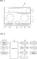
- Fig. 1 is a plan view showing an induction heating cooking apparatus according to Embodiment 1.
- Fig. 2 is an exploded perspective view showing the induction heating cooking apparatus according to Embodiment 1.
- an induction heating cooking apparatus 100 includes a top plate 20 in an upper part of the induction heating cooking apparatus 100.
- the top plate 20 has a tabular shape, and a cooking container 6 such as a pan and a pot is placed on the top plate 20.
- the top plate 20 includes a first top plate 3 and a second top plate 4.
- the first top plate 3 is adjacent to the second top plate 4.
- the first top plate 3 is provided at a front portion of the top plate 20.
- the second top plate 4 is provided at a rear portion of the top plate 20.
- the first top plate 3 and the second top plate 4 are joined together to be flush with each other.
- the first top plate 3 is made of a material that allows a flow of eddy currents into the cooking container 6 to inductively heat the cooking container 6 without blocking a high-frequency magnetic field from a heating coil 11 described later.
- the first top plate 3 is, for example, made of a material such as heat-resistant tempered glass and crystallized glass.
- the second top plate 4 is made of a material having a higher thermal conductivity than does the material of the first top plate 3.
- the second top plate 4 is, for example, made of a material such as aluminum, copper, aluminum nitride, silicon, stainless steel, and alumina.
- the thermal conductivity of crystallized glass is 1 [W/mK].
- the thermal conductivity of aluminum is 236 [W/mK].
- the thermal conductivity of copper is 398 [W/mK].
- the thermal conductivity of aluminum nitride is 285 [W/mK].
- the thermal conductivity of silicon is 168 [W/mK].
- the thermal conductivity of stainless steel ranges from 16.7 to 20.9 [W/mK].
- the thermal conductivity of alumina is 30 [W/mK].
- the second top plate 4 has, for example, approximately 16 times to 400 times higher thermal conductivity as compared with the first top plate 3.
- the heating coil 11 and a heating coil 12 are disposed below the first top plate 3 and configured to inductively heat the cooking container 6 placed on the first top plate 3.
- the heating coil 11 and the heating coil 12 are arranged laterally in a front portion of the induction heating cooking apparatus 100.
- the first top plate 3 has a first heating zone 1 and a second heating zone 2, which correspond to respective heating zones of the heating coil 11 and the heating coil 12 to roughly show sites on which the cooking container 6 is placed.
- the first heating zone 1 and the second heating zone 2 are, for example, circular marks corresponding to outlines of the heating coil 11 and the heating coil 12.
- the first heating zone 1 and the second heating zone 2 are formed by a method such as applying paint to the first top plate 3 and printing the marks on the first top plate 3.
- the heating coil 11 and the heating coil 12 each include a lead wire that is made up of a metal coated for insulation and that is wound into circles.
- a core of the lead wire is, for example, made of any metal such as copper and aluminum.
- a cooling device 13 is disposed below the second top plate 4 and configured to cool the cooking container 6 placed on the second top plate 4.
- the cooling device 13 is disposed at a substantially lateral middle place below the second top plate 4 in a rear portion of the induction heating cooking apparatus 100.
- the second top plate 4 has a cooling zone 5, which corresponds to a cooling zone of the cooling device 13 to roughly show a site on which the cooking container 6 is placed.
- the cooling zone 5 is, for example, formed above the cooling device 13 and is a mark of a rectangle corresponding to an outline of the cooling device 13.
- the cooling zone 5 is formed by a method such as applying paint to the second top plate 4 and printing the mark on the second top plate 4.
- a shape of the cooling zone 5 is not limited to the rectangle.
- the cooling zone 5 may have any shape that roughly shows a zone within which the cooking container 6 placed on the second top plate 4 is allowed to be cooled by the cooling device 13.
- the shape of the cooling zone 5 may be circular, elliptical, or square.
- a plurality of the cooling zones 5 may be formed for one unit of the cooling device 13.
- a plurality of the cooling devices 13 may be disposed such that a plurality of the cooling zones 5 corresponding to cooling zones of the respective cooling devices 13 are formed.
- One piece of the cooling zone 5 may be formed for a plurality of the cooling devices 13.
- the cooling device 13 for example, includes a Peltier element.
- the cooling device 13 cools a bottom face of the second top plate 4 to cool the cooking container 6 placed on the second top plate 4.
- the cooling device 13 will be detailed later.
- Fig. 3 is a plan view illustrating a first region and a second region in the induction heating cooking apparatus according to Embodiment 1.
- the top plate 20 includes a first region 21 and a second region 22.
- the second region 22 is a region having a higher thermal conductivity than does the first region 21.
- the second top plate 4 made of the material having a higher thermal conductivity than does the material of the first top plate 3 includes the second region 22 of the top plate 20.
- the first top plate 3 includes the first region 21 of the top plate 20.
- the heating coil 11 and the heating coil 12 each inductively heat the cooking container 6 placed on the first region 21 of the top plate 20.
- the cooling device 13 cools the cooking container 6 placed on the second region 22 of the top plate 20.
- An operation unit 40a and an operation unit 40b are disposed as input devices at a front portion of the top plate 20 to supply electric power and choose a cooking menu or other settings when the cooking container 6 or other utensil is heated by either of the heating coil 11 and the heating coil 12.
- a display 41a and a display 41b are disposed as informing units in the vicinity of the operation unit 40a and the operation unit 40b and configured to display operating states of the heating coils and command details or other information input from the operation unit 40a and the operation unit 40b.
- An operation unit 40c is disposed as an input device at a middle place at a front portion of the top plate 20 to supply electric power and choose a cooking menu or other settings when the cooking container 6 or other utensil is cooled by the cooling device 13.
- a display 41c is disposed as an informing unit in the vicinity of the operation unit 40c and configured to display an operating state of the cooling device 13 and command details or other information input from the operation unit 40c.
- the operation units 40a to 40c are mechanical switches, such as push switches and tact switches, or touch switches used to detect an input operation by a change in electrode static capacitance.
- the displays 41a to 41c are, for example, devices such as LCDs and LEDs.
- the operation unit 40a and the display 41a may be integrated together to be used as an operation display unit.
- the operation unit 40b and the display 41b may be integrated together to be used as an operation display unit.
- the operation unit 40c and the display 41c may be integrated together to be used as an operation display unit.
- the operation display unit is, for example, a device such as a touch screen that includes a touch switch disposed on a top face of an LCD.
- the LCD is an acronym for "liquid crystal device”.
- the LED is an acronym for "light emitting diode”.
- the operation units 40a, 40b, 40c and the displays 41a, 41b, 41c are provided for the heating coil 11, the heating coil 12, and the cooling device 13, respectively, as described above.
- this example does not place a limitation on the numbers of the units and the displays provided for the coils and the device.
- one operation unit 40 and one display 41 may be shared by the heating coil 11, the heating coil 12, and the cooling device 13.
- drive circuits 46 are disposed to drive the heating coil 11, the heating coil 12, and the cooling device 13, and a controller 45 is disposed to control overall operation of the induction heating cooking apparatus 100 including the drive circuits 46.
- the controller 45 includes dedicated hardware or a CPU that executes programs stored in a memory.
- the CPU is an acronym for "central processing unit".
- the CPU is also called a central processor, a processor unit, an arithmetic unit, a microprocessor, a microcomputer, or a processor.
- the controller 45 When the controller 45 is dedicated hardware, the controller 45, for example, represents a single circuit, a composite circuit, an ASIC, an FPGA, or a combination of any of these parts.
- the controller 45 may include pieces of hardware configured to be used as respective functional units or may be one piece of hardware configured to be used as functional units.
- the ASIC is an acronym for "application specific integrated circuit”.
- the FPGA is an acronym for "field-programmable gate array”.
- the controller 45 When the controller 45 is a CPU, the controller 45 implements functions by software, firmware, or a combination of software and firmware.
- the software and the firmware are written as programs and are stored in a memory.
- the CPU reads programs stored in the memory and executes the programs, so that the controller 45 implements functions.
- the memory described herein is, for example, a non-volatile or volatile semiconductor memory such as a RAM, a ROM, a flash memory, an EPROM, and an EEPROM.
- the controller 45 may implement the functions partly by dedicated hardware and may implement the functions partly by software or firmware.
- the RAM is an acronym for "random access memory”.
- the ROM is an acronym for "read only memory”.
- the EPROM is an acronym for "erasable programmable read only memory”.
- the EEPROM is an acronym for "electrically erasable programmable read-only memory”.
- a temperature sensor 42 (shown by a broken line in Fig. 1 ) is disposed on the bottom face of the second top plate 4.
- the temperature sensor 42 is, for example, a thermistor.
- the temperature sensor 42 is, for example, provided in the vicinity of the cooling device 13.
- the temperature sensor 42 detects temperature by heat transmitted from the cooking container 6 to the second top plate 4.
- the controller 45 controls the cooling device 13 in response to the temperature detected by the temperature sensor 42.
- a fan 60 is disposed inside the induction heating cooking apparatus 100.
- the fan 60 is used to suction air from an exterior of a body of the induction heating cooking apparatus 100 into an interior of the body via an air inlet (not shown) to supply cooling air to the interior of the body.
- the cooling air supplied into the body cools parts and the cooling device 13 in the interior of the body and is then discharged to the exterior of the body via an air outlet (not shown).
- Fig. 4 is a block diagram showing a configuration of the induction heating cooking apparatus according to Embodiment 1.
- the heating coil 11 is driven and controlled by a drive circuit 46a.
- the heating coil 12 is driven and controlled by a drive circuit 46b.
- the cooling device 13 is driven and controlled by a drive circuit 46c.
- the drive circuit 46a and the drive circuit 46b each include an inverter circuit.
- the drive circuit 46a and the drive circuit 46b each convert alternating-current (AC) power supplied from an AC power source into AC power having a high frequency ranging approximately from 20 kHz to 100 kHz and output the AC power to the corresponding one of the heating coil 11 and the heating coil 12.
- the drive circuit 46c includes a direct-current (DC) power supply circuit.
- the drive circuit 46c converts AC power supplied from the AC power source into DC power of any given wattage and outputs the DC power to the cooling device 13.
- the controller 45 controls operation of the drive circuits 46a to 46c and the fan 60.
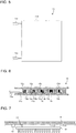
- Fig. 5 is a plan view showing the cooling device in the induction heating cooking apparatus according to Embodiment 1.
- Fig. 6 is a schematic side view showing a configuration of the cooling device in the induction heating cooking apparatus according to Embodiment 1.
- the cooling device 13 includes a plurality of p-type thermoelectric semiconductors 13a, a plurality of n-type thermoelectric semiconductors 13b, a plurality of electrodes 13c, and a pair of insulating parts 13d.
- the pair of the insulating parts 13d are, for example, each made of an insulating material such as ceramics.
- the pair of the insulating parts 13d have a tabular shape.
- the pair of the insulating parts 13d are provided opposite to each other.
- the plurality of the p-type thermoelectric semiconductors 13a and the plurality of the n-type thermoelectric semiconductors 13b are provided between the pair of the insulating parts 13d.
- the p-type thermoelectric semiconductors 13a and the n-type thermoelectric semiconductors 13b are provided in an alternate order.
- the electrode 13c electrically connects the p-type thermoelectric semiconductor 13a and the n-type thermoelectric semiconductor 13b provided adjacent to each other.
- One end of a lead wire 13e is connected to an end of the electrode 13c.
- the other end of the lead wire 13e is connected to the drive circuit 46c, and a DC voltage from the drive circuit 46c is applied to the cooling device 13.
- the p-type thermoelectric semiconductors 13a, the n-type thermoelectric semiconductors 13b, and the electrodes 13c compose a Peltier element.
- a DC current flowing into the electrodes 13c causes heat generation or heat removal at a face of the electrode 13c where the p-type thermoelectric semiconductor 13a and the n-type thermoelectric semiconductor 13b touch the electrode 13c.
- one of the pair of the insulating parts 13d that represents a cold side is cooled, and the other of the pair of the insulating parts 13d that represents a hot side is heated.
- Fig. 7 is a schematic side view showing how the cooling device is placed in the induction heating cooking apparatus according to Embodiment 1.
- the cooling device 13 is firmly attached to the bottom face of the second top plate 4 such that the insulating part 13d representing the cold side faces the second top plate 4.
- a heat radiation unit 61 is firmly attached to the other of the pair of the insulating parts 13d representing the hot side.
- the heat radiation unit 61 for example, includes radiating fins. Cooling air is supplied from the fan 60 to the heat radiation unit 61 to radiate heat from the insulating part 13d representing the hot side.
- a fan may be further provided beside or below the heat radiation unit 61 and configured to send cooling air to the heat radiation unit 61.
- a substance such as thermal grease and an adhesive is applied to an interface between the cooling device 13 and the second top plate 4 and an interface between the cooling device 13 and the heat radiation unit 61 so that firm attachment is achieved without interposition of air.
- Embodiment 1 operation of the induction heating cooking apparatus according to Embodiment 1 will be described such that description is separately given of heat cooking involving inductively heating the cooking container 6 and of cool cooking involving cooling the cooking container 6.
- a user places the cooking container 6 such as a pan and a pot on the first heating zone 1 or the second heating zone 2 of the first top plate 3.
- the cooking container 6 is placed on the first heating zone 1 will be described below.
- the user inputs a command via the operation unit 40a to start heating.
- the controller 45 controls operation of the drive circuit 46a. For instance, the controller 45 allows frequency at which a high-frequency current is supplied from the drive circuit 46a to the heating coil 11 to vary depending on the specified electric power level.
- the heating coil 11 When a high-frequency current flows into the heating coil 11, the heating coil 11 generates a high-frequency magnetic field, causing an eddy current to flow through a bottom of the cooking container 6 placed on the first heating zone 1 in a direction in which to cancel a flux change. Because of a loss of the flowing eddy current, the cooking container 6 is heated.
- a user places the cooking container 6 such as a pan and a pot on the cooling zone 5 of the second top plate 4. Then, the user inputs a command via the operation unit 40c to start cooling. In response to a level of electric power specified by the command input from the operation unit 40c, the controller 45 controls operation of the drive circuit 46c.
- the command input from the operation unit 40c is, for example, a command input to set a cooling temperature in three levels “Low”, “Medium”, and "High” or a command input to set a value of temperature for the cooking container 6.
- the controller 45 controls the operation of the drive circuit 46c. For instance, in response to the level of cooling temperature, the controller 45 controls activation and deactivation of the supply of DC power to the cooling device 13. Specifically, when the level set by the input command is "High”, the controller 45 activates and keeps the supply of DC power from the drive circuit 46c to the cooling device 13. When the level set by the input command is "Medium”, the controller 45 switches periodically between activation and deactivation of the supply of DC power from the drive circuit 46c to the cooling device 13.
- the controller 45 switches periodically between activation and deactivation of the supply of DC power from the drive circuit 46c to the cooling device 13 such that a length of time for which the supply is deactivated is long compared with that when the level set by the input command is "Medium”.
- the controller 45 controls the cooling device 13 to cause the temperature detected by the temperature sensor 42 to reach the set temperature. Specifically, when the temperature detected by the temperature sensor 42 is lower than the set temperature, the controller 45 activates the supply of DC power from the drive circuit 46c to the cooling device 13. When the temperature detected by the temperature sensor 42 is higher than or equal to the set temperature, the controller 45 deactivates the supply of DC power from the drive circuit 46c to the cooling device 13.
- the control of the cooling device 13 exercised by the controller 45 is not limited to the control described above, and the controller 45 may use any other temperature control.
- the controller 45 may, for example, control the cooling device 13 to increase the on-duty ratio for the drive circuit 46c in response to an increase in difference between the set temperature and the temperature detected by the temperature sensor 42.
- the second top plate 4 to which the insulating part 13d representing the cold side is firmly attached is cooled, and the cooking container 6 placed on the second top plate 4 is cooled.
- the heat cooking and the cool cooking can be performed concurrently or can be performed in sequence.
- a user may place two respective cooking containers 6 on the first heating zone 1 and the cooling zone 5 to perform concurrently the heat cooking by the heating coil 11 and the cool cooking by the cooling device 13.
- a user may place one cooking container 6 on the first heating zone 1 to perform the heat cooking by the heating coil 11 and may then move the cooking container 6 placed on the first heating zone 1 to the cooling zone 5 to perform the cool cooking by the cooling device 13.
- the induction heating cooking apparatus includes the heating coil 11 provided below the first region 21 included in the top plate 20 and the cooling device 13 provided below the second region 22 included in the top plate 20.
- the second region 22 has a higher thermal conductivity than does the first region 21.
- This configuration allows the cooling device 13 to cool the cooking container 6 with increased speed as compared with a case in which the thermal conductivity of the second region 22 of the top plate 20 is equal to the thermal conductivity of the first region 21.
- the induction heating cooking apparatus is configured to hinder the propagation of bacteria in cooked stuff compared with a case of natural cooling.
- the induction heating cooking apparatus enables the user to perform the heat cooking and the cool cooking concurrently or in sequence.
- stuff in the cooking container 6 can be cooked through coordination between cooling and heating.
- the cool cooking performed after the heat cooking allows improved infiltration of seasonings into cooked stuff in the cooking container 6, enhancing a fine flavor of the cooked stuff.
- the top plate 20 has a tabular shape. Thus, after heat cooking with the cooking container 6 placed on the first region 21 of the top plate 20, the cooking container 6 can be readily moved from the first region 21 to the second region 22 of the top plate 20 by sliding the cooking container 6 without holding up the cooking container 6. This facilitates coordination between the heat cooking and the cool cooking.
- the top plate 20 includes the first top plate 3 including the first region 21 and the second top plate 4 including the second region 22.
- the second top plate 4 is made of a material having a higher thermal conductivity than does the material of the first top plate 3. This configuration allows the cooking container 6 placed on the second top plate 4 to be cooled with increased speed as compared with a case in which the thermal conductivity of the second top plate 4 is equal to the thermal conductivity of the first top plate 3. This shortens cooking time required for cool cooking of the cooking container 6.
- the first top plate 3 and the second top plate 4 are joined together to be flush with each other.
- the cooking container 6 can be readily moved from the first top plate 3 to the second top plate 4 by sliding the cooking container 6 without holding up the cooking container 6. This facilitates coordination between the heat cooking and the cool cooking.
- the first top plate 3 is, for example, made of a material such as heat-resistant tempered glass and crystallized glass.
- the second top plate 4 is, for example, made of a material such as aluminum, copper, aluminum nitride, silicon, stainless steel, and alumina.
- heat-resistant tempered glass and crystallized glass each are expensive compared with any of aluminum, copper, aluminum nitride, silicon, stainless steel, and alumina.
- this configuration provides a decrease in amount of usage of a material such as heat-resistant tempered glass and crystallized glass and contributes to a reduction in manufacturing costs as compared with a case in which the top plate 20 is completely made of a material such as heat-resistant tempered glass and crystallized glass.
- the second top plate 4 is provided adjacent to the first top plate 3.
- the cooking container 6 can be readily moved from the first top plate 3 to the second top plate 4. This facilitates coordination between the heat cooking and the cool cooking.
- the top plate 20 has the cooling zone 5 above the cooling device 13 to show a site on which the cooking container 6 is placed. This allows the user to readily locate the site on which the cooking container 6 is to be placed to perform the cool cooking. Thus, the cooking container 6 can be readily placed on the site where the cool cooking is enabled with the cooling device 13. This provides efficient cooling of the cooking container 6.
- the induction heating cooking apparatus includes the temperature sensor 42 provided on a bottom face of the second region 22 included in the top plate 20 and the controller 45 configured to control the cooling device 13 in response to the temperature detected by the temperature sensor 42.
- This configuration can reduce both an error in detection of temperature of and a time delay before detection of a change in temperature of the cooking container 6 as compared with a case in which the thermal conductivity of the second region 22 of the top plate 20 is equal to the thermal conductivity of the first region 21. This enables quick and accurate detection of the temperature of the cooking container 6 and temperature control with high accuracy based on detected signals from the temperature sensor 42 during cool cooking.
- the induction heating cooking apparatus includes the controller 45 configured to control the cooling device 13 in response to a command input from any of the operation units 40. This configuration allows the user to readily set the operation of the cooling device 13, such as starting and stopping of the cool cooking.
- the induction heating cooking apparatus includes the controller 45 configured to control the cooling device 13 to cause the temperature detected by the temperature sensor 42 to reach the set temperature. This enables temperature control with high accuracy based on detected signals from the temperature sensor 42 during cool cooking.
- Fig. 8 is a schematic side view showing how the cooling device is placed in an induction heating cooking apparatus according to a first modification example of Embodiment 1.
- the cooling device 13 may be firmly attached to a bottom face of the top plate 20 with an elastic body 62.
- the elastic body 62 is interposed between the insulating part 13d representing the cold side of the cooling device 13 and the second top plate 4.
- the elastic body 62 is made of a material having a higher thermal conductivity than does the material of the first top plate 3.
- the elastic body 62 is, for example, made of silicon or other material.
- This configuration allows the cooling device 13 and the second top plate 4 to be firmly attached to each other such that an air layer is not interposed between the cooling device 13 and the second top plate 4. This provides improved efficiency in the cooling of the cooking container 6 by the cooling device 13 and allows the cooling of the cooking container 6 with increased speed.
- Fig. 9 is an exploded perspective view showing an induction heating cooking apparatus according to a second modification example of Embodiment 1.
- the first top plate 3 and the second top plate 4 may be arranged laterally.
- the first top plate 3 is provided at a left portion of the top plate 20.
- the second top plate 4 is provided at a right portion of the top plate 20.
- the first top plate 3 is provided adjacent to the second top plate 4.
- the first top plate 3 and the second top plate 4 are joined together to be flush with each other.
- the heating coil 11 is disposed below the first top plate 3.
- the heating coil 11 is provided in a front left portion of the induction heating cooking apparatus 100.
- the first top plate 3 has the first heating zone 1 corresponding to a heating zone of the heating coil 11.
- the cooling device 13 is disposed below the second top plate 4.
- the cooling device 13 is disposed in a right portion of the induction heating cooking apparatus 100.
- the second top plate 4 has the cooling zone 5 corresponding to a cooling zone of the cooling device 13. Lateral positions of the first heating zone 1 and the cooling zone 5 are not limited as shown.
- This configuration can also produce effects similar to those in Embodiment 1 described above.
- Embodiment 2 A configuration of an induction heating cooking apparatus 100 according to Embodiment 2, in particular, differences between Embodiment 2 and Embodiment 1 described above, will be described below. In the following description, components identical to those in Embodiment 1 are assigned with the same reference signs, and descriptions of the components will be omitted.
- Fig. 10 is a plan view showing an induction heating cooking apparatus according to Embodiment 2.
- a first top plate 3 has an opening portion 31.
- a second top plate 4 is provided in the opening portion 31 formed in the first top plate 3. The first top plate 3 and the second top plate 4 are joined together to be flush with each other.
- the opening portion 31 in the first top plate 3 is, for example, formed above a cooling device 13 and has a shape of a rectangle corresponding to an outline of the cooling device 13. In Embodiment 2, a mark of a cooling zone 5 may be omitted.
- the second top plate 4 is provided in the opening portion 31 formed in the first top plate 3. This configuration can also produce effects similar to those in Embodiment 1 described above. As the first top plate 3 and the second top plate 4 are made of different materials, the top plates differ in color in most cases. Thus, even if the mark of the cooling zone 5 is omitted, a color of the second top plate 4 enables the user to identify a cooling zone of the cooling device 13.
- Fig. 11 is a plan view showing an induction heating cooking apparatus according to a first modification example of Embodiment 2.
- the first top plate 3 may have a cutout 32.
- the second top plate 4 is provided in the cutout 32 formed in the first top plate 3.
- the first top plate 3 and the second top plate 4 are joined together to be flush with each other.
- This configuration can also produce effects similar to those in the first modification example described above.
- the shapes of the opening portion 31 and the cutout 32 described above may be any shapes, such as circular, square, and elliptical, other than the rectangular shapes.
- Fig. 12 is a plan view showing an induction heating cooking apparatus according to a second modification example of Embodiment 2.
- the first top plate 3 may have two pieces of an opening portion 33a and an opening portion 33b.
- the opening portion 33a and the opening portion 33b are, for example, elliptical.
- a second top plate 4a is provided in the opening portion 33a formed in the first top plate 3, and a second top plate 4b is provided in the opening portion 33b formed in the first top plate 3.
- Respective cooling devices 13 are provided below the opening portion 33a and the opening portion 33b.
- This configuration can also produce effects similar to those in the first modification example described above.
- the shapes of the opening portion 33a and the opening portion 33b described above may be any shapes, such as circular, square, and rectangular, other than the elliptical shapes.
- the number of the opening portions may be any other than the two.
- An operation unit 40c may be used to select any of the opening portion 33a and the opening portion 33b to control operation of the cooling device 13 provided below the selected one of the opening portion 33a and the opening portion 33b.
- Embodiment 3 A configuration of an induction heating cooking apparatus 100 according to Embodiment 3, in particular, differences between Embodiment 3 and Embodiments 1 and 2 described above, will be described below.
- components identical to those in Embodiments 1 and 2 are assigned with the same reference signs, and descriptions of the components will be omitted.
- Fig. 13 is a longitudinal cross-sectional view showing a top plate of an induction heating cooking apparatus according to Embodiment 3.
- a heat insulator 70 is provided between a first top plate 3 and a second top plate 4.
- the heat insulator 70 is made of a material having a lower thermal conductivity than does the material of the first top plate 3.
- the heat insulator 70 is, for example, made of an epoxy resin or other material.
- the thermal conductivity of epoxy resin ranges from 0.15 to 0.21 [W/mK].
- a top plate 20 in Embodiment 3 is equivalent to the top plate in Embodiment 1 that includes a heat insulator 70 disposed at a location where the first top plate 3 and the second top plate 4 are joined together.
- the top plate 20 in Embodiment 3 is equivalent to the top plate in Embodiment 2 that includes a heat insulator 70 at a location where the opening portion 31 in the first top plate 3 and the second top plate 4 are joined together.
- the induction heating cooking apparatus includes the heat insulator 70, which is provided between the first top plate 3 and the second top plate 4 and is made of a material having a lower thermal conductivity than does the material of the first top plate 3.
- This configuration hinders transfer of heat between the first top plate 3 and the second top plate 4.
- this configuration can prevent the first top plate 3 and the second top plate 4 from thermally interfering with each other. This prevents the heat cooking from increasing the temperature of the second top plate 4 and the cool cooking from decreasing the temperature of the first top plate 3.
- the induction heating cooking apparatus enables efficient heat cooking and cool cooking.
- Embodiment 4 A configuration of an induction heating cooking apparatus 100 according to Embodiment 4, in particular, differences between Embodiment 4 and Embodiments 1 to 3 described above, will be described below. In the following description, components identical to those in Embodiments 1 to 3 are assigned with the same reference signs, and descriptions of the components will be omitted.
- Fig. 14 is a longitudinal cross-sectional view showing a top plate of an induction heating cooking apparatus according to Embodiment 4.
- a middle of a side end of a first top plate 3 has a protrusion 71a.
- An end of a second top plate 4 has a recess 71b into which the protrusion 71 a of the first top plate 3 is fit.
- the protrusion 71a and the recess 71b are fit together and hence the first top plate 3 and the second top plate 4 are joined together in a watertight manner.
- a top plate 20 in Embodiment 4 is equivalent to a top plate formed such that the first top plate 3 and the second top plate 4 in Embodiment 1 that are joined together in a watertight manner.
- the top plate 20 in Embodiment 4 is equivalent to a structure of the opening portion 31 in the first top plate 3 and the second top plate 4 in Embodiment 2 that are joined together in a watertight manner.
- a heat insulator 70 may be disposed in an interface between the first top plate 3 and the second top plate 4, which are joined together.
- Embodiment 4 as described above, the first top plate 3 and the second top plate 4 are joined together in a watertight manner.
- This configuration hinders ingress of moisture into the induction heating cooking apparatus 100 through a gap at a location where the first top plate 3 and the second top plate 4 are joined together. For instance, even if broth or other liquid in a cooking container 6 has boiled over during hot cooking, this configuration obstructs ingress of the moisture of the broth or other liquid into the induction heating cooking apparatus 100. This prevents malfunction and deterioration of a device caused by moisture ingress into the induction heating cooking apparatus 100.
- the joint structure may form any configuration as long as the first top plate 3 and the second top plate 4 are joined together in a watertight manner.
- the first top plate 3 and the second top plate 4 may be joined together by being firmly attached to each other with a sealing material interposed between the first top plate 3 and the second top plate 4.
- the sealing material may be a material having a lower thermal conductivity than does the material of the first top plate 3 to be used as both a heat insulator 70 in Embodiment 3 and a watertight joint structure.
- Fig. 15 is a longitudinal cross-sectional view showing a top plate of an induction heating cooking apparatus according to a modification example of Embodiment 4.
- a lower part of a side end of the first top plate 3 has a protrusion 72a.
- the protrusion 72a has a recess 72b depressed downward.
- An upper part of a side end of the second top plate 4 has a protrusion 73a.
- the protrusion 73a has a protrusion 73b projecting downward.
- the top plates are provided such that the protrusion 72a of the first top plate 3 and the protrusion 73a of the second top plate 4 are arranged vertically and the protrusion 73b and the recess 72b are fit together. As a result, the first top plate 3 and the second top plate 4 are joined together in a watertight manner.
- the interface between the first top plate 3 and the second top plate 4 is provided with a plurality of the recesses and the protrusions. This configuration provides improved waterproofness between the first top plate 3 and the second top plate 4.
- Embodiment 5 A configuration of an induction heating cooking apparatus 100 according to Embodiment 5, in particular, differences between Embodiment 5 and Embodiment 1 described above, will be described below. In the following description, components identical to those in Embodiment 1 are assigned with the same reference signs, and descriptions of the components will be omitted.
- Fig. 16 is an exploded perspective view showing an induction heating cooking apparatus according to Embodiment 5.
- Fig. 17 is a longitudinal cross-sectional view showing a top plate of the induction heating cooking apparatus according to Embodiment 5.
- an induction heating cooking apparatus 100 includes a top plate 80 in an upper part of the induction heating cooking apparatus 100.
- the top plate 80 has a tabular shape, and a cooking container 6 such as a pan and a pot is placed on the top plate 80.
- a first region 21 included in the top plate 80 is occupied by a first material 81.
- a second region 22 included in the top plate 80 is occupied by a mixture of the first material 81 and a second material 82.
- the second material 82 has a higher thermal conductivity than does the first material 81.
- the first material 81 is, for example, a material such as heat-resistant tempered glass and crystallized glass.
- the second material 82 is, for example, a material such as aluminum, copper, aluminum nitride, silicon, stainless steel, and alumina.
- the second material 82 is, for example, formed as particles.
- a rest of the configuration is similar to that in Embodiment 1 described above.
- the top plate 80 includes the first region 21 occupied by the first material 81 and the second region 22 occupied by a mixture of the first material 81 and the second material 82 having a higher thermal conductivity than does the first material 81.
- This configuration allows a cooling device 13 to cool the cooking container 6 with increased speed as compared with a case in which the first material 81 is not mixed as the material of the second region 22 of the top plate 80.
- the induction heating cooking apparatus is configured to hinder the propagation of bacteria in cooked stuff compared with a case of natural cooling.
- the top plate 80 has a tabular shape. Thus, after heat cooking with the cooking container 6 placed on the first region 21 of the top plate 20, the cooking container 6 can be readily moved from the first region 21 to the second region 22 of the top plate 80 by sliding the cooking container 6 without holding up the cooking container 6. This facilitates coordination between the heat cooking and the cool cooking.
- the first region 21 and the second region 22 of the top plate 80 are integrated together. This prevents ingress of moisture into the induction heating cooking apparatus 100.
- Embodiment 6 A configuration of an induction heating cooking apparatus 100 according to Embodiment 6, in particular, differences between Embodiment 6 and Embodiments 1 to 5 described above, will be described below. In the following description, components identical to those in Embodiments 1 to 5 are assigned with the same reference signs, and descriptions of the components will be omitted.
- Fig. 18 is a schematic longitudinal cross-sectional view showing an internal configuration of an induction heating cooking apparatus according to Embodiment 6.
- an induction heating cooking apparatus 100 includes a drain pan 90 and a discharge unit 93.
- a rest of the configuration is similar to that in Embodiment 1 described above.
- illustration of some components is omitted.
- the drain pan 90 is provided below a cooling device 13 to receive condensed water generated on a bottom face of a second top plate 4.
- the discharge unit 93 discharges the condensed water stored in the drain pan 90.
- the discharge unit 93 includes a water pipe 91 connected to a bottom of the drain pan 90 and a drain container 92 that stores condensed water drained through the water pipe 91.
- An upper part of the drain container 92, which is detachable, is locked to the second top plate 4 with a lock piece 92a.
- the second top plate 4 includes an openable lid 94 disposed above the drain container 92.
- Cool cooking performed with the cooling device 13 causes moisture in the air to condense (dew condensation) on the second top plate 4 around the cooling device 13 and thus generates condensed water.
- the condensed water adhering to the bottom face of the second top plate 4 drips downward and is stored in the drain pan 90.
- the condensed water stored in the drain pan 90 is stored into the drain container 92 via the water pipe 91.
- the user opens the openable lid 94 of the second top plate 4, removes the drain container 92 out from the apparatus body, and discards the condensed water in the drain container 92.
- the induction heating cooking apparatus includes the drain pan 90, which is provided below the cooling device 13 to receive condensed water generated on the bottom face of a top plate 20, and the discharge unit 93 configured to discharge the condensed water stored in the drain pan 90.
- This configuration prevents condensed water generated around the cooling device 13 by cool cooking from adhering to electrical parts and other structural components inside the induction heating cooking apparatus 100. This hinders the electrical parts inside the induction heating cooking apparatus 100 from having an electric short circuit. This configuration also prevents the electrical parts and other structural components inside the induction heating cooking apparatus 100 from deteriorating or corroding by moisture adhesion.
- the cooling device includes a Peltier element. This example, however, does not place a limitation on the scope of the present disclosure.
- the cooling device may have any configuration as long as the cooling device cools the cooking container 6 placed on the second region 22.
- a cooling device according to Embodiment 7 will be described that is applied as an evaporator included in a refrigerant circuit.
- Fig. 19 is a drawing showing a cooling device and a refrigerant circuit in an induction heating cooking apparatus according to Embodiment 7.
- a refrigerant circuit 200 includes a compressor 201, a condenser 202, an expansion valve 203, and a cooling device 204, which is an evaporator.
- the compressor 201, the condenser 202, the expansion valve 203, and the cooling device 204 are connected annularly in order by a refrigerant pipe.
- the compressor 201 suctions refrigerant having low temperature and low pressure and discharges the refrigerant having high temperature and high pressure.
- the high-temperature and high-pressure refrigerant discharged from the compressor 201 flows into the condenser 202 to transfer heat.
- the refrigerant that has fallen in temperature turns into refrigerant in the form of liquid and flows out from the condenser 202.
- the refrigerant flowing out from the condenser 202 is decompressed by the expansion valve 203 to turn into two-phase gas-liquid refrigerant and flows into the cooling device 204, which is the evaporator.
- the refrigerant flowing into the cooling device 204 removes heat from the cooking container 6 and thereby evaporates to turn into refrigerant in the form of gas and flows out from the cooling device 204.
- the refrigerant flowing out from the cooling device 204 is suctioned into the compressor 201.
- This configuration allows the induction heating cooking apparatus to cool the cooking container 6 placed on a top plate 20 and thus produce effects similar to those in Embodiments 1 to 6 described above.
Landscapes
- Physics & Mathematics (AREA)
- Electromagnetism (AREA)
- Induction Heating Cooking Devices (AREA)
- Electric Stoves And Ranges (AREA)
Abstract
Description
- The present disclosure relates to an induction heating cooking apparatus including a top plate on which a cooking container is placed.
- Some electromagnetic cooking apparatus has been proposed, for example, that includes a placement part on which a cooking utensil is placed and a heating device that is disposed below the placement part and configured to heat the cooking utensil placed on the placement part by electromagnetic induction (see Patent Literature 1). The electromagnetic cooking apparatus includes a cooling device that is in contact with a face of the placement part opposite another face on which the cooking utensil is placed and that is configured to cool the cooking utensil placed on the placement part. The placement part is, for example, made of crystallized glass.
- Patent Literature 1:
Japanese Unexamined Patent Application Publication No. 2008-287938 - The electromagnetic cooking apparatus described in
Patent Literature 1 cools the cooking utensil by allowing the cooling device, which is in contact with a bottom face of the placement part, to remove heat transmitted from the cooking utensil to the placement part. As a result, a problem with the electromagnetic cooking apparatus is that cooling the cooking container by the cooling device requires time as compared with heating the cooking container by electromagnetic induction. - An object of the present disclosure, which has been accomplished to solve the problem described above, is to provide an induction heating cooking apparatus designed to cool a cooking container placed on a top plate with increased speed. Solution to Problem
- An induction heating cooking apparatus according to an embodiment of the present disclosure includes a top plate having a tabular shape and including a first region and a second region having a higher thermal conductivity than does the first region, a heating coil provided below the first region included in the top plate and configured to inductively heat a cooking container placed on the first region, and a cooling device provided below the second region included in the top plate and configured to cool a cooking container placed on the second region. Advantageous Effects of Invention
- The induction heating cooking apparatus according to an embodiment of the present disclosure includes the heating coil configured to inductively heat the cooking container placed on the first region included in the top plate and the cooling device configured to cool the cooking container placed on the second region included in the top plate. In the top plate, the second region has a higher thermal conductivity than does the first region. This configuration allows the cooling device to cool the cooking container with increased speed as compared with a case in which the thermal conductivity of a region of the top plate above the cooling device is equal to the thermal conductivity of the first region.
-
- [
Fig. 1] Fig. 1 is a plan view showing an induction heating cooking apparatus according toEmbodiment 1. - [
Fig. 2] Fig. 2 is an exploded perspective view showing the induction heating cooking apparatus according toEmbodiment 1. - [
Fig. 3] Fig. 3 is a plan view illustrating a first region and a second region in the induction heating cooking apparatus according toEmbodiment 1. - [
Fig. 4] Fig. 4 is a block diagram showing a configuration of the induction heating cooking apparatus according toEmbodiment 1. - [
Fig. 5] Fig. 5 is a plan view showing a cooling device in the induction heating cooking apparatus according toEmbodiment 1. - [
Fig. 6] Fig. 6 is a schematic side view showing a configuration of the cooling device in the induction heating cooking apparatus according toEmbodiment 1. - [
Fig. 7] Fig. 7 is a schematic side view showing how the cooling device is placed in the induction heating cooking apparatus according toEmbodiment 1. - [
Fig. 8] Fig. 8 is a schematic side view showing how the cooling device is placed in an induction heating cooking apparatus according to a first modification example ofEmbodiment 1. - [
Fig. 9] Fig. 9 is an exploded perspective view showing an induction heating cooking apparatus according to a second modification example ofEmbodiment 1. - [
Fig. 10] Fig. 10 is a plan view showing an induction heating cooking apparatus according toEmbodiment 2. - [
Fig. 11] Fig. 11 is a plan view showing an induction heating cooking apparatus according to a first modification example ofEmbodiment 2. - [
Fig. 12] Fig. 12 is a plan view showing an induction heating cooking apparatus according to a second modification example ofEmbodiment 2. - [
Fig. 13] Fig. 13 is a longitudinal cross-sectional view showing a top plate of an induction heating cooking apparatus according toEmbodiment 3. - [
Fig. 14] Fig. 14 is a longitudinal cross-sectional view showing a top plate of an induction heating cooking apparatus according toEmbodiment 4. - [
Fig. 15] Fig. 15 is a longitudinal cross-sectional view showing a top plate of an induction heating cooking apparatus according to a modification example ofEmbodiment 4. - [
Fig. 16] Fig. 16 is an exploded perspective view showing an induction heating cooking apparatus according toEmbodiment 5. - [
Fig. 17] Fig. 17 is a longitudinal cross-sectional view showing a top plate of the induction heating cooking apparatus according toEmbodiment 5. - [
Fig. 18] Fig. 18 is a schematic longitudinal cross-sectional view showing an internal configuration of an induction heating cooking apparatus according toEmbodiment 6. - [
Fig. 19] Fig. 19 is a drawing showing a cooling device and a refrigerant circuit in an induction heating cooking apparatus according to Embodiment 7. Description of Embodiments -
Fig. 1 is a plan view showing an induction heating cooking apparatus according toEmbodiment 1. -
Fig. 2 is an exploded perspective view showing the induction heating cooking apparatus according toEmbodiment 1. - As shown in
Figs. 1 and2 , an inductionheating cooking apparatus 100 includes atop plate 20 in an upper part of the inductionheating cooking apparatus 100. Thetop plate 20 has a tabular shape, and acooking container 6 such as a pan and a pot is placed on thetop plate 20. Thetop plate 20 includes a firsttop plate 3 and a secondtop plate 4. The firsttop plate 3 is adjacent to the secondtop plate 4. The firsttop plate 3 is provided at a front portion of thetop plate 20. The secondtop plate 4 is provided at a rear portion of thetop plate 20. The firsttop plate 3 and the secondtop plate 4 are joined together to be flush with each other. - The first
top plate 3 is made of a material that allows a flow of eddy currents into thecooking container 6 to inductively heat thecooking container 6 without blocking a high-frequency magnetic field from aheating coil 11 described later. The firsttop plate 3 is, for example, made of a material such as heat-resistant tempered glass and crystallized glass. - The second
top plate 4 is made of a material having a higher thermal conductivity than does the material of the firsttop plate 3. The secondtop plate 4 is, for example, made of a material such as aluminum, copper, aluminum nitride, silicon, stainless steel, and alumina. For instance, the thermal conductivity of crystallized glass is 1 [W/mK]. The thermal conductivity of aluminum is 236 [W/mK]. The thermal conductivity of copper is 398 [W/mK]. The thermal conductivity of aluminum nitride is 285 [W/mK]. The thermal conductivity of silicon is 168 [W/mK]. The thermal conductivity of stainless steel ranges from 16.7 to 20.9 [W/mK]. The thermal conductivity of alumina is 30 [W/mK]. In other words, the secondtop plate 4 has, for example, approximately 16 times to 400 times higher thermal conductivity as compared with the firsttop plate 3. - The
heating coil 11 and aheating coil 12 are disposed below the firsttop plate 3 and configured to inductively heat thecooking container 6 placed on the firsttop plate 3. Theheating coil 11 and theheating coil 12 are arranged laterally in a front portion of the inductionheating cooking apparatus 100. The firsttop plate 3 has afirst heating zone 1 and asecond heating zone 2, which correspond to respective heating zones of theheating coil 11 and theheating coil 12 to roughly show sites on which thecooking container 6 is placed. Thefirst heating zone 1 and thesecond heating zone 2 are, for example, circular marks corresponding to outlines of theheating coil 11 and theheating coil 12. Thefirst heating zone 1 and thesecond heating zone 2 are formed by a method such as applying paint to the firsttop plate 3 and printing the marks on the firsttop plate 3. - The
heating coil 11 and theheating coil 12 each include a lead wire that is made up of a metal coated for insulation and that is wound into circles. A core of the lead wire is, for example, made of any metal such as copper and aluminum. When a high-frequency current is supplied to theheating coil 11 and theheating coil 12, the heating coils each generate a high-frequency magnetic field. As a result, thecooking container 6 placed on the firsttop plate 3 directly above theheating coil 11 and theheating coil 12 is inductively heated. - A cooling
device 13 is disposed below the secondtop plate 4 and configured to cool thecooking container 6 placed on the secondtop plate 4. Thecooling device 13 is disposed at a substantially lateral middle place below the secondtop plate 4 in a rear portion of the inductionheating cooking apparatus 100. The secondtop plate 4 has acooling zone 5, which corresponds to a cooling zone of thecooling device 13 to roughly show a site on which thecooking container 6 is placed. Thecooling zone 5 is, for example, formed above thecooling device 13 and is a mark of a rectangle corresponding to an outline of thecooling device 13. Thecooling zone 5 is formed by a method such as applying paint to the secondtop plate 4 and printing the mark on the secondtop plate 4. - A shape of the
cooling zone 5 is not limited to the rectangle. Thecooling zone 5 may have any shape that roughly shows a zone within which thecooking container 6 placed on the secondtop plate 4 is allowed to be cooled by the coolingdevice 13. For instance, the shape of thecooling zone 5 may be circular, elliptical, or square. A plurality of thecooling zones 5 may be formed for one unit of thecooling device 13. Alternatively, a plurality of thecooling devices 13 may be disposed such that a plurality of thecooling zones 5 corresponding to cooling zones of therespective cooling devices 13 are formed. One piece of thecooling zone 5 may be formed for a plurality of thecooling devices 13. - The
cooling device 13, for example, includes a Peltier element. Thecooling device 13 cools a bottom face of the secondtop plate 4 to cool thecooking container 6 placed on the secondtop plate 4. Thecooling device 13 will be detailed later. -
Fig. 3 is a plan view illustrating a first region and a second region in the induction heating cooking apparatus according toEmbodiment 1. - As shown in
Fig. 3 , thetop plate 20 includes afirst region 21 and asecond region 22. Thesecond region 22 is a region having a higher thermal conductivity than does thefirst region 21. In other words, the secondtop plate 4 made of the material having a higher thermal conductivity than does the material of the firsttop plate 3 includes thesecond region 22 of thetop plate 20. The firsttop plate 3 includes thefirst region 21 of thetop plate 20. Theheating coil 11 and theheating coil 12 each inductively heat thecooking container 6 placed on thefirst region 21 of thetop plate 20. Thecooling device 13 cools thecooking container 6 placed on thesecond region 22 of thetop plate 20. -
Figs. 1 and2 will be referenced again. - An
operation unit 40a and anoperation unit 40b are disposed as input devices at a front portion of thetop plate 20 to supply electric power and choose a cooking menu or other settings when thecooking container 6 or other utensil is heated by either of theheating coil 11 and theheating coil 12. Adisplay 41a and adisplay 41b are disposed as informing units in the vicinity of theoperation unit 40a and theoperation unit 40b and configured to display operating states of the heating coils and command details or other information input from theoperation unit 40a and theoperation unit 40b. - An
operation unit 40c is disposed as an input device at a middle place at a front portion of thetop plate 20 to supply electric power and choose a cooking menu or other settings when thecooking container 6 or other utensil is cooled by the coolingdevice 13. Adisplay 41c is disposed as an informing unit in the vicinity of theoperation unit 40c and configured to display an operating state of thecooling device 13 and command details or other information input from theoperation unit 40c. - The
operation units 40a to 40c are mechanical switches, such as push switches and tact switches, or touch switches used to detect an input operation by a change in electrode static capacitance. Thedisplays 41a to 41c are, for example, devices such as LCDs and LEDs. Theoperation unit 40a and thedisplay 41a may be integrated together to be used as an operation display unit. Theoperation unit 40b and thedisplay 41b may be integrated together to be used as an operation display unit. Theoperation unit 40c and thedisplay 41c may be integrated together to be used as an operation display unit. The operation display unit is, for example, a device such as a touch screen that includes a touch switch disposed on a top face of an LCD. The LCD is an acronym for "liquid crystal device". The LED is an acronym for "light emitting diode". - The
operation units displays heating coil 11, theheating coil 12, and thecooling device 13, respectively, as described above. However, this example does not place a limitation on the numbers of the units and the displays provided for the coils and the device. For instance, one operation unit 40 and one display 41 may be shared by theheating coil 11, theheating coil 12, and thecooling device 13. - In the induction
heating cooking apparatus 100, drivecircuits 46 are disposed to drive theheating coil 11, theheating coil 12, and thecooling device 13, and acontroller 45 is disposed to control overall operation of the inductionheating cooking apparatus 100 including thedrive circuits 46. - The
controller 45 includes dedicated hardware or a CPU that executes programs stored in a memory. The CPU is an acronym for "central processing unit". The CPU is also called a central processor, a processor unit, an arithmetic unit, a microprocessor, a microcomputer, or a processor. - When the
controller 45 is dedicated hardware, thecontroller 45, for example, represents a single circuit, a composite circuit, an ASIC, an FPGA, or a combination of any of these parts. Thecontroller 45 may include pieces of hardware configured to be used as respective functional units or may be one piece of hardware configured to be used as functional units. The ASIC is an acronym for "application specific integrated circuit". The FPGA is an acronym for "field-programmable gate array". - When the
controller 45 is a CPU, thecontroller 45 implements functions by software, firmware, or a combination of software and firmware. The software and the firmware are written as programs and are stored in a memory. The CPU reads programs stored in the memory and executes the programs, so that thecontroller 45 implements functions. The memory described herein is, for example, a non-volatile or volatile semiconductor memory such as a RAM, a ROM, a flash memory, an EPROM, and an EEPROM. - The
controller 45 may implement the functions partly by dedicated hardware and may implement the functions partly by software or firmware. The RAM is an acronym for "random access memory". The ROM is an acronym for "read only memory". The EPROM is an acronym for "erasable programmable read only memory". The EEPROM is an acronym for "electrically erasable programmable read-only memory". - A temperature sensor 42 (shown by a broken line in
Fig. 1 ) is disposed on the bottom face of the secondtop plate 4. Thetemperature sensor 42 is, for example, a thermistor. Thetemperature sensor 42 is, for example, provided in the vicinity of thecooling device 13. Thetemperature sensor 42 detects temperature by heat transmitted from thecooking container 6 to the secondtop plate 4. Thecontroller 45 controls thecooling device 13 in response to the temperature detected by thetemperature sensor 42. - A
fan 60 is disposed inside the inductionheating cooking apparatus 100. Thefan 60 is used to suction air from an exterior of a body of the inductionheating cooking apparatus 100 into an interior of the body via an air inlet (not shown) to supply cooling air to the interior of the body. The cooling air supplied into the body cools parts and thecooling device 13 in the interior of the body and is then discharged to the exterior of the body via an air outlet (not shown). -
Fig. 4 is a block diagram showing a configuration of the induction heating cooking apparatus according toEmbodiment 1. - As shown in
Fig. 4 , theheating coil 11 is driven and controlled by adrive circuit 46a. Theheating coil 12 is driven and controlled by adrive circuit 46b. Thecooling device 13 is driven and controlled by adrive circuit 46c. Thedrive circuit 46a and thedrive circuit 46b each include an inverter circuit. Thedrive circuit 46a and thedrive circuit 46b each convert alternating-current (AC) power supplied from an AC power source into AC power having a high frequency ranging approximately from 20 kHz to 100 kHz and output the AC power to the corresponding one of theheating coil 11 and theheating coil 12. Thedrive circuit 46c includes a direct-current (DC) power supply circuit. Thedrive circuit 46c converts AC power supplied from the AC power source into DC power of any given wattage and outputs the DC power to thecooling device 13. In response to input from theoperation units 40a to 40c and thetemperature sensor 42, thecontroller 45 controls operation of thedrive circuits 46a to 46c and thefan 60. -
Fig. 5 is a plan view showing the cooling device in the induction heating cooking apparatus according toEmbodiment 1. -
Fig. 6 is a schematic side view showing a configuration of the cooling device in the induction heating cooking apparatus according toEmbodiment 1. - As shown in
Figs. 5 and 6 , thecooling device 13 includes a plurality of p-typethermoelectric semiconductors 13a, a plurality of n-typethermoelectric semiconductors 13b, a plurality ofelectrodes 13c, and a pair of insulatingparts 13d. The pair of the insulatingparts 13d are, for example, each made of an insulating material such as ceramics. The pair of the insulatingparts 13d have a tabular shape. The pair of the insulatingparts 13d are provided opposite to each other. - The plurality of the p-type
thermoelectric semiconductors 13a and the plurality of the n-typethermoelectric semiconductors 13b are provided between the pair of the insulatingparts 13d. The p-typethermoelectric semiconductors 13a and the n-typethermoelectric semiconductors 13b are provided in an alternate order. Theelectrode 13c electrically connects the p-typethermoelectric semiconductor 13a and the n-typethermoelectric semiconductor 13b provided adjacent to each other. One end of alead wire 13e is connected to an end of theelectrode 13c. The other end of thelead wire 13e is connected to thedrive circuit 46c, and a DC voltage from thedrive circuit 46c is applied to thecooling device 13. - The p-type
thermoelectric semiconductors 13a, the n-typethermoelectric semiconductors 13b, and theelectrodes 13c compose a Peltier element. A DC current flowing into theelectrodes 13c causes heat generation or heat removal at a face of theelectrode 13c where the p-typethermoelectric semiconductor 13a and the n-typethermoelectric semiconductor 13b touch theelectrode 13c. Thus, one of the pair of the insulatingparts 13d that represents a cold side is cooled, and the other of the pair of the insulatingparts 13d that represents a hot side is heated. -
Fig. 7 is a schematic side view showing how the cooling device is placed in the induction heating cooking apparatus according toEmbodiment 1. - As shown in
Fig. 7 , thecooling device 13 is firmly attached to the bottom face of the secondtop plate 4 such that the insulatingpart 13d representing the cold side faces the secondtop plate 4. Aheat radiation unit 61 is firmly attached to the other of the pair of the insulatingparts 13d representing the hot side. Theheat radiation unit 61, for example, includes radiating fins. Cooling air is supplied from thefan 60 to theheat radiation unit 61 to radiate heat from the insulatingpart 13d representing the hot side. - A fan may be further provided beside or below the
heat radiation unit 61 and configured to send cooling air to theheat radiation unit 61. Preferably, a substance such as thermal grease and an adhesive is applied to an interface between the coolingdevice 13 and the secondtop plate 4 and an interface between the coolingdevice 13 and theheat radiation unit 61 so that firm attachment is achieved without interposition of air. - Next, operation of the induction heating cooking apparatus according to
Embodiment 1 will be described such that description is separately given of heat cooking involving inductively heating thecooking container 6 and of cool cooking involving cooling thecooking container 6. - A user places the
cooking container 6 such as a pan and a pot on thefirst heating zone 1 or thesecond heating zone 2 of the firsttop plate 3. A case in which thecooking container 6 is placed on thefirst heating zone 1 will be described below. - The user inputs a command via the
operation unit 40a to start heating. In response to a level of electric power specified by the command input from theoperation unit 40a, thecontroller 45 controls operation of thedrive circuit 46a. For instance, thecontroller 45 allows frequency at which a high-frequency current is supplied from thedrive circuit 46a to theheating coil 11 to vary depending on the specified electric power level. - When a high-frequency current flows into the
heating coil 11, theheating coil 11 generates a high-frequency magnetic field, causing an eddy current to flow through a bottom of thecooking container 6 placed on thefirst heating zone 1 in a direction in which to cancel a flux change. Because of a loss of the flowing eddy current, thecooking container 6 is heated. - A user places the
cooking container 6 such as a pan and a pot on thecooling zone 5 of the secondtop plate 4. Then, the user inputs a command via theoperation unit 40c to start cooling. In response to a level of electric power specified by the command input from theoperation unit 40c, thecontroller 45 controls operation of thedrive circuit 46c. The command input from theoperation unit 40c is, for example, a command input to set a cooling temperature in three levels "Low", "Medium", and "High" or a command input to set a value of temperature for thecooking container 6. - In response to the command input from the
operation unit 40c, thecontroller 45 controls the operation of thedrive circuit 46c. For instance, in response to the level of cooling temperature, thecontroller 45 controls activation and deactivation of the supply of DC power to thecooling device 13. Specifically, when the level set by the input command is "High", thecontroller 45 activates and keeps the supply of DC power from thedrive circuit 46c to thecooling device 13. When the level set by the input command is "Medium", thecontroller 45 switches periodically between activation and deactivation of the supply of DC power from thedrive circuit 46c to thecooling device 13. When the level set by the input command is "Low", thecontroller 45 switches periodically between activation and deactivation of the supply of DC power from thedrive circuit 46c to thecooling device 13 such that a length of time for which the supply is deactivated is long compared with that when the level set by the input command is "Medium". - For instance, the
controller 45 controls thecooling device 13 to cause the temperature detected by thetemperature sensor 42 to reach the set temperature. Specifically, when the temperature detected by thetemperature sensor 42 is lower than the set temperature, thecontroller 45 activates the supply of DC power from thedrive circuit 46c to thecooling device 13. When the temperature detected by thetemperature sensor 42 is higher than or equal to the set temperature, thecontroller 45 deactivates the supply of DC power from thedrive circuit 46c to thecooling device 13. The control of thecooling device 13 exercised by thecontroller 45 is not limited to the control described above, and thecontroller 45 may use any other temperature control. Thecontroller 45 may, for example, control thecooling device 13 to increase the on-duty ratio for thedrive circuit 46c in response to an increase in difference between the set temperature and the temperature detected by thetemperature sensor 42. - When DC power is supplied to the
cooling device 13, the secondtop plate 4 to which the insulatingpart 13d representing the cold side is firmly attached is cooled, and thecooking container 6 placed on the secondtop plate 4 is cooled. - The heat cooking and the cool cooking can be performed concurrently or can be performed in sequence. For instance, a user may place two
respective cooking containers 6 on thefirst heating zone 1 and thecooling zone 5 to perform concurrently the heat cooking by theheating coil 11 and the cool cooking by the coolingdevice 13. For instance, a user may place onecooking container 6 on thefirst heating zone 1 to perform the heat cooking by theheating coil 11 and may then move thecooking container 6 placed on thefirst heating zone 1 to thecooling zone 5 to perform the cool cooking by the coolingdevice 13. - As described above, the induction heating cooking apparatus according to
Embodiment 1 includes theheating coil 11 provided below thefirst region 21 included in thetop plate 20 and thecooling device 13 provided below thesecond region 22 included in thetop plate 20. In thetop plate 20, thesecond region 22 has a higher thermal conductivity than does thefirst region 21. This configuration allows thecooling device 13 to cool thecooking container 6 with increased speed as compared with a case in which the thermal conductivity of thesecond region 22 of thetop plate 20 is equal to the thermal conductivity of thefirst region 21. This shortens cooking time required for cool cooking of thecooking container 6. This also shortens time required until temperature of cooked stuff in thecooking container 6, after heat cooking, falls to a temperature suitable for preservation of food in a refrigerator. As a result, the induction heating cooking apparatus is configured to hinder the propagation of bacteria in cooked stuff compared with a case of natural cooling. - The induction heating cooking apparatus enables the user to perform the heat cooking and the cool cooking concurrently or in sequence. Thus, stuff in the
cooking container 6 can be cooked through coordination between cooling and heating. The cool cooking performed after the heat cooking allows improved infiltration of seasonings into cooked stuff in thecooking container 6, enhancing a fine flavor of the cooked stuff. - The
top plate 20 has a tabular shape. Thus, after heat cooking with thecooking container 6 placed on thefirst region 21 of thetop plate 20, thecooking container 6 can be readily moved from thefirst region 21 to thesecond region 22 of thetop plate 20 by sliding thecooking container 6 without holding up thecooking container 6. This facilitates coordination between the heat cooking and the cool cooking. - In
Embodiment 1, thetop plate 20 includes the firsttop plate 3 including thefirst region 21 and the secondtop plate 4 including thesecond region 22. The secondtop plate 4 is made of a material having a higher thermal conductivity than does the material of the firsttop plate 3. This configuration allows thecooking container 6 placed on the secondtop plate 4 to be cooled with increased speed as compared with a case in which the thermal conductivity of the secondtop plate 4 is equal to the thermal conductivity of the firsttop plate 3. This shortens cooking time required for cool cooking of thecooking container 6. - The first
top plate 3 and the secondtop plate 4 are joined together to be flush with each other. Thus, after heat cooking with thecooking container 6 placed on the firsttop plate 3, thecooking container 6 can be readily moved from the firsttop plate 3 to the secondtop plate 4 by sliding thecooking container 6 without holding up thecooking container 6. This facilitates coordination between the heat cooking and the cool cooking. - The first
top plate 3 is, for example, made of a material such as heat-resistant tempered glass and crystallized glass. The secondtop plate 4 is, for example, made of a material such as aluminum, copper, aluminum nitride, silicon, stainless steel, and alumina. In most cases, heat-resistant tempered glass and crystallized glass each are expensive compared with any of aluminum, copper, aluminum nitride, silicon, stainless steel, and alumina. Thus, this configuration provides a decrease in amount of usage of a material such as heat-resistant tempered glass and crystallized glass and contributes to a reduction in manufacturing costs as compared with a case in which thetop plate 20 is completely made of a material such as heat-resistant tempered glass and crystallized glass. - In
Embodiment 1, the secondtop plate 4 is provided adjacent to the firsttop plate 3. Thus, after heat cooking with thecooking container 6 placed on the firsttop plate 3, thecooking container 6 can be readily moved from the firsttop plate 3 to the secondtop plate 4. This facilitates coordination between the heat cooking and the cool cooking. - In
Embodiment 1, thetop plate 20 has thecooling zone 5 above thecooling device 13 to show a site on which thecooking container 6 is placed. This allows the user to readily locate the site on which thecooking container 6 is to be placed to perform the cool cooking. Thus, thecooking container 6 can be readily placed on the site where the cool cooking is enabled with thecooling device 13. This provides efficient cooling of thecooking container 6. - In
Embodiment 1, the induction heating cooking apparatus includes thetemperature sensor 42 provided on a bottom face of thesecond region 22 included in thetop plate 20 and thecontroller 45 configured to control thecooling device 13 in response to the temperature detected by thetemperature sensor 42. This configuration can reduce both an error in detection of temperature of and a time delay before detection of a change in temperature of thecooking container 6 as compared with a case in which the thermal conductivity of thesecond region 22 of thetop plate 20 is equal to the thermal conductivity of thefirst region 21. This enables quick and accurate detection of the temperature of thecooking container 6 and temperature control with high accuracy based on detected signals from thetemperature sensor 42 during cool cooking. - In
Embodiment 1, the induction heating cooking apparatus includes thecontroller 45 configured to control thecooling device 13 in response to a command input from any of the operation units 40. This configuration allows the user to readily set the operation of thecooling device 13, such as starting and stopping of the cool cooking. - The induction heating cooking apparatus includes the
controller 45 configured to control thecooling device 13 to cause the temperature detected by thetemperature sensor 42 to reach the set temperature. This enables temperature control with high accuracy based on detected signals from thetemperature sensor 42 during cool cooking. -
Fig. 8 is a schematic side view showing how the cooling device is placed in an induction heating cooking apparatus according to a first modification example ofEmbodiment 1. - As shown in
Fig. 8 , thecooling device 13 may be firmly attached to a bottom face of thetop plate 20 with anelastic body 62. In other words, theelastic body 62 is interposed between the insulatingpart 13d representing the cold side of thecooling device 13 and the secondtop plate 4. Theelastic body 62 is made of a material having a higher thermal conductivity than does the material of the firsttop plate 3. Theelastic body 62 is, for example, made of silicon or other material. - This configuration allows the
cooling device 13 and the secondtop plate 4 to be firmly attached to each other such that an air layer is not interposed between the coolingdevice 13 and the secondtop plate 4. This provides improved efficiency in the cooling of thecooking container 6 by the coolingdevice 13 and allows the cooling of thecooking container 6 with increased speed. -
Fig. 9 is an exploded perspective view showing an induction heating cooking apparatus according to a second modification example ofEmbodiment 1. - As shown in
Fig. 9 , the firsttop plate 3 and the secondtop plate 4 may be arranged laterally. The firsttop plate 3 is provided at a left portion of thetop plate 20. The secondtop plate 4 is provided at a right portion of thetop plate 20. The firsttop plate 3 is provided adjacent to the secondtop plate 4. The firsttop plate 3 and the secondtop plate 4 are joined together to be flush with each other. - The
heating coil 11 is disposed below the firsttop plate 3. Theheating coil 11 is provided in a front left portion of the inductionheating cooking apparatus 100. The firsttop plate 3 has thefirst heating zone 1 corresponding to a heating zone of theheating coil 11. Thecooling device 13 is disposed below the secondtop plate 4. Thecooling device 13 is disposed in a right portion of the inductionheating cooking apparatus 100. The secondtop plate 4 has thecooling zone 5 corresponding to a cooling zone of thecooling device 13. Lateral positions of thefirst heating zone 1 and thecooling zone 5 are not limited as shown. - This configuration can also produce effects similar to those in
Embodiment 1 described above. - A configuration of an induction
heating cooking apparatus 100 according toEmbodiment 2, in particular, differences betweenEmbodiment 2 andEmbodiment 1 described above, will be described below. In the following description, components identical to those inEmbodiment 1 are assigned with the same reference signs, and descriptions of the components will be omitted. -
Fig. 10 is a plan view showing an induction heating cooking apparatus according toEmbodiment 2. - As shown in
Fig. 10 , a firsttop plate 3 has an openingportion 31. A secondtop plate 4 is provided in the openingportion 31 formed in the firsttop plate 3. The firsttop plate 3 and the secondtop plate 4 are joined together to be flush with each other. - The opening
portion 31 in the firsttop plate 3 is, for example, formed above acooling device 13 and has a shape of a rectangle corresponding to an outline of thecooling device 13. InEmbodiment 2, a mark of acooling zone 5 may be omitted. - In
Embodiment 2, as described above, the secondtop plate 4 is provided in the openingportion 31 formed in the firsttop plate 3. This configuration can also produce effects similar to those inEmbodiment 1 described above. As the firsttop plate 3 and the secondtop plate 4 are made of different materials, the top plates differ in color in most cases. Thus, even if the mark of thecooling zone 5 is omitted, a color of the secondtop plate 4 enables the user to identify a cooling zone of thecooling device 13. -
Fig. 11 is a plan view showing an induction heating cooking apparatus according to a first modification example ofEmbodiment 2. - As shown in
Fig. 11 , the firsttop plate 3 may have acutout 32. The secondtop plate 4 is provided in thecutout 32 formed in the firsttop plate 3. The firsttop plate 3 and the secondtop plate 4 are joined together to be flush with each other. - This configuration can also produce effects similar to those in the first modification example described above.
- The shapes of the opening
portion 31 and thecutout 32 described above may be any shapes, such as circular, square, and elliptical, other than the rectangular shapes. -
Fig. 12 is a plan view showing an induction heating cooking apparatus according to a second modification example ofEmbodiment 2. - As shown in
Fig. 12 , the firsttop plate 3 may have two pieces of anopening portion 33a and anopening portion 33b. Theopening portion 33a and theopening portion 33b are, for example, elliptical. A secondtop plate 4a is provided in theopening portion 33a formed in the firsttop plate 3, and a secondtop plate 4b is provided in theopening portion 33b formed in the firsttop plate 3.Respective cooling devices 13 are provided below theopening portion 33a and theopening portion 33b. - This configuration can also produce effects similar to those in the first modification example described above.
- The shapes of the
opening portion 33a and theopening portion 33b described above may be any shapes, such as circular, square, and rectangular, other than the elliptical shapes. The number of the opening portions may be any other than the two. Anoperation unit 40c may be used to select any of theopening portion 33a and theopening portion 33b to control operation of thecooling device 13 provided below the selected one of theopening portion 33a and theopening portion 33b. - A configuration of an induction
heating cooking apparatus 100 according toEmbodiment 3, in particular, differences betweenEmbodiment 3 and Embodiments 1 and 2 described above, will be described below. In the following description, components identical to those inEmbodiments -
Fig. 13 is a longitudinal cross-sectional view showing a top plate of an induction heating cooking apparatus according toEmbodiment 3. - As shown in
Fig. 13 , aheat insulator 70 is provided between a firsttop plate 3 and a secondtop plate 4. Theheat insulator 70 is made of a material having a lower thermal conductivity than does the material of the firsttop plate 3. Theheat insulator 70 is, for example, made of an epoxy resin or other material. The thermal conductivity of epoxy resin ranges from 0.15 to 0.21 [W/mK]. - A rest of the configuration is similar to that in
Embodiment top plate 20 inEmbodiment 3 is equivalent to the top plate inEmbodiment 1 that includes aheat insulator 70 disposed at a location where the firsttop plate 3 and the secondtop plate 4 are joined together. Thetop plate 20 inEmbodiment 3 is equivalent to the top plate inEmbodiment 2 that includes aheat insulator 70 at a location where the openingportion 31 in the firsttop plate 3 and the secondtop plate 4 are joined together. - In
Embodiment 3, as described above, the induction heating cooking apparatus includes theheat insulator 70, which is provided between the firsttop plate 3 and the secondtop plate 4 and is made of a material having a lower thermal conductivity than does the material of the firsttop plate 3. This configuration hinders transfer of heat between the firsttop plate 3 and the secondtop plate 4. In other words, when the heat cooking and the cool cooking are performed concurrently or in sequence, this configuration can prevent the firsttop plate 3 and the secondtop plate 4 from thermally interfering with each other. This prevents the heat cooking from increasing the temperature of the secondtop plate 4 and the cool cooking from decreasing the temperature of the firsttop plate 3. As a result, the induction heating cooking apparatus enables efficient heat cooking and cool cooking. - A configuration of an induction
heating cooking apparatus 100 according toEmbodiment 4, in particular, differences betweenEmbodiment 4 andEmbodiments 1 to 3 described above, will be described below. In the following description, components identical to those inEmbodiments 1 to 3 are assigned with the same reference signs, and descriptions of the components will be omitted. -
Fig. 14 is a longitudinal cross-sectional view showing a top plate of an induction heating cooking apparatus according toEmbodiment 4. - As shown in
Fig. 14 , a middle of a side end of a firsttop plate 3 has aprotrusion 71a. An end of a secondtop plate 4 has arecess 71b into which theprotrusion 71 a of the firsttop plate 3 is fit. Theprotrusion 71a and therecess 71b are fit together and hence the firsttop plate 3 and the secondtop plate 4 are joined together in a watertight manner. - A rest of the configuration is similar to that in
Embodiment top plate 20 inEmbodiment 4 is equivalent to a top plate formed such that the firsttop plate 3 and the secondtop plate 4 inEmbodiment 1 that are joined together in a watertight manner. Thetop plate 20 inEmbodiment 4 is equivalent to a structure of the openingportion 31 in the firsttop plate 3 and the secondtop plate 4 inEmbodiment 2 that are joined together in a watertight manner. InEmbodiment 4, similarly toEmbodiment 3 described above, aheat insulator 70 may be disposed in an interface between the firsttop plate 3 and the secondtop plate 4, which are joined together. - In
Embodiment 4, as described above, the firsttop plate 3 and the secondtop plate 4 are joined together in a watertight manner. This configuration hinders ingress of moisture into the inductionheating cooking apparatus 100 through a gap at a location where the firsttop plate 3 and the secondtop plate 4 are joined together. For instance, even if broth or other liquid in acooking container 6 has boiled over during hot cooking, this configuration obstructs ingress of the moisture of the broth or other liquid into the inductionheating cooking apparatus 100. This prevents malfunction and deterioration of a device caused by moisture ingress into the inductionheating cooking apparatus 100. - With the structure described above, the
protrusion 71a and therecess 71b are fit together. This example, however, does not place a limitation on the scope of the present disclosure. The joint structure may form any configuration as long as the firsttop plate 3 and the secondtop plate 4 are joined together in a watertight manner. For instance, the firsttop plate 3 and the secondtop plate 4 may be joined together by being firmly attached to each other with a sealing material interposed between the firsttop plate 3 and the secondtop plate 4. The sealing material may be a material having a lower thermal conductivity than does the material of the firsttop plate 3 to be used as both aheat insulator 70 inEmbodiment 3 and a watertight joint structure. -
Fig. 15 is a longitudinal cross-sectional view showing a top plate of an induction heating cooking apparatus according to a modification example ofEmbodiment 4. - As shown in
Fig. 15 , a lower part of a side end of the firsttop plate 3 has aprotrusion 72a. Theprotrusion 72a has arecess 72b depressed downward. An upper part of a side end of the secondtop plate 4 has aprotrusion 73a. Theprotrusion 73a has aprotrusion 73b projecting downward. The top plates are provided such that theprotrusion 72a of the firsttop plate 3 and theprotrusion 73a of the secondtop plate 4 are arranged vertically and theprotrusion 73b and therecess 72b are fit together. As a result, the firsttop plate 3 and the secondtop plate 4 are joined together in a watertight manner. - In this manner, the interface between the first
top plate 3 and the secondtop plate 4 is provided with a plurality of the recesses and the protrusions. This configuration provides improved waterproofness between the firsttop plate 3 and the secondtop plate 4. - A configuration of an induction
heating cooking apparatus 100 according toEmbodiment 5, in particular, differences betweenEmbodiment 5 andEmbodiment 1 described above, will be described below. In the following description, components identical to those inEmbodiment 1 are assigned with the same reference signs, and descriptions of the components will be omitted. -
Fig. 16 is an exploded perspective view showing an induction heating cooking apparatus according toEmbodiment 5. -
Fig. 17 is a longitudinal cross-sectional view showing a top plate of the induction heating cooking apparatus according toEmbodiment 5. - As shown in
Figs. 16 and17 , an inductionheating cooking apparatus 100 according toEmbodiment 5 includes atop plate 80 in an upper part of the inductionheating cooking apparatus 100. Thetop plate 80 has a tabular shape, and acooking container 6 such as a pan and a pot is placed on thetop plate 80. Afirst region 21 included in thetop plate 80 is occupied by afirst material 81. Asecond region 22 included in thetop plate 80 is occupied by a mixture of thefirst material 81 and asecond material 82. Thesecond material 82 has a higher thermal conductivity than does thefirst material 81. Thefirst material 81 is, for example, a material such as heat-resistant tempered glass and crystallized glass. Thesecond material 82 is, for example, a material such as aluminum, copper, aluminum nitride, silicon, stainless steel, and alumina. Thesecond material 82 is, for example, formed as particles. - A rest of the configuration is similar to that in
Embodiment 1 described above. - In
Embodiment 5, as described above, thetop plate 80 includes thefirst region 21 occupied by thefirst material 81 and thesecond region 22 occupied by a mixture of thefirst material 81 and thesecond material 82 having a higher thermal conductivity than does thefirst material 81. This configuration allows acooling device 13 to cool thecooking container 6 with increased speed as compared with a case in which thefirst material 81 is not mixed as the material of thesecond region 22 of thetop plate 80. This shortens cooking time required for cool cooking of thecooking container 6. This also shortens time required until temperature of cooked stuff in thecooking container 6, after heat cooking, falls to a temperature suitable for preservation of food in a refrigerator. As a result, the induction heating cooking apparatus is configured to hinder the propagation of bacteria in cooked stuff compared with a case of natural cooling. - The
top plate 80 has a tabular shape. Thus, after heat cooking with thecooking container 6 placed on thefirst region 21 of thetop plate 20, thecooking container 6 can be readily moved from thefirst region 21 to thesecond region 22 of thetop plate 80 by sliding thecooking container 6 without holding up thecooking container 6. This facilitates coordination between the heat cooking and the cool cooking. - The
first region 21 and thesecond region 22 of thetop plate 80 are integrated together. This prevents ingress of moisture into the inductionheating cooking apparatus 100. - A configuration of an induction
heating cooking apparatus 100 according toEmbodiment 6, in particular, differences betweenEmbodiment 6 andEmbodiments 1 to 5 described above, will be described below. In the following description, components identical to those inEmbodiments 1 to 5 are assigned with the same reference signs, and descriptions of the components will be omitted. -
Fig. 18 is a schematic longitudinal cross-sectional view showing an internal configuration of an induction heating cooking apparatus according toEmbodiment 6. - As shown in
Fig. 18 , an inductionheating cooking apparatus 100 according toEmbodiment 6 includes adrain pan 90 and adischarge unit 93. A rest of the configuration is similar to that inEmbodiment 1 described above. InFig. 17 , illustration of some components is omitted. - The
drain pan 90 is provided below acooling device 13 to receive condensed water generated on a bottom face of a secondtop plate 4. Thedischarge unit 93 discharges the condensed water stored in thedrain pan 90. Thedischarge unit 93 includes awater pipe 91 connected to a bottom of thedrain pan 90 and adrain container 92 that stores condensed water drained through thewater pipe 91. An upper part of thedrain container 92, which is detachable, is locked to the secondtop plate 4 with alock piece 92a. The secondtop plate 4 includes anopenable lid 94 disposed above thedrain container 92. - A process for storing and discarding the condensed water will be described.
- Cool cooking performed with the
cooling device 13 causes moisture in the air to condense (dew condensation) on the secondtop plate 4 around thecooling device 13 and thus generates condensed water. The condensed water adhering to the bottom face of the secondtop plate 4 drips downward and is stored in thedrain pan 90. The condensed water stored in thedrain pan 90 is stored into thedrain container 92 via thewater pipe 91. The user opens theopenable lid 94 of the secondtop plate 4, removes thedrain container 92 out from the apparatus body, and discards the condensed water in thedrain container 92. - In
Embodiment 6, as described above, the induction heating cooking apparatus includes thedrain pan 90, which is provided below thecooling device 13 to receive condensed water generated on the bottom face of atop plate 20, and thedischarge unit 93 configured to discharge the condensed water stored in thedrain pan 90. This configuration prevents condensed water generated around thecooling device 13 by cool cooking from adhering to electrical parts and other structural components inside the inductionheating cooking apparatus 100. This hinders the electrical parts inside the inductionheating cooking apparatus 100 from having an electric short circuit. This configuration also prevents the electrical parts and other structural components inside the inductionheating cooking apparatus 100 from deteriorating or corroding by moisture adhesion. - In
Embodiments 1 to 6 described above, the cooling device includes a Peltier element. This example, however, does not place a limitation on the scope of the present disclosure. The cooling device may have any configuration as long as the cooling device cools thecooking container 6 placed on thesecond region 22. A cooling device according to Embodiment 7 will be described that is applied as an evaporator included in a refrigerant circuit. -
Fig. 19 is a drawing showing a cooling device and a refrigerant circuit in an induction heating cooking apparatus according to Embodiment 7. - As shown in
Fig. 19 , arefrigerant circuit 200 includes acompressor 201, acondenser 202, anexpansion valve 203, and acooling device 204, which is an evaporator. Thecompressor 201, thecondenser 202, theexpansion valve 203, and thecooling device 204 are connected annularly in order by a refrigerant pipe. - The
compressor 201 suctions refrigerant having low temperature and low pressure and discharges the refrigerant having high temperature and high pressure. The high-temperature and high-pressure refrigerant discharged from thecompressor 201 flows into thecondenser 202 to transfer heat. The refrigerant that has fallen in temperature turns into refrigerant in the form of liquid and flows out from thecondenser 202. The refrigerant flowing out from thecondenser 202 is decompressed by theexpansion valve 203 to turn into two-phase gas-liquid refrigerant and flows into thecooling device 204, which is the evaporator. The refrigerant flowing into thecooling device 204 removes heat from thecooking container 6 and thereby evaporates to turn into refrigerant in the form of gas and flows out from thecooling device 204. The refrigerant flowing out from thecooling device 204 is suctioned into thecompressor 201. - This configuration allows the induction heating cooking apparatus to cool the
cooking container 6 placed on atop plate 20 and thus produce effects similar to those inEmbodiments 1 to 6 described above. - 1
first heating zone 2second heating zone 3 firsttop plate 4 secondtop plate 4a secondtop plate 4b secondtop plate 5cooling zone 6cooking container 11heating coil 12heating coil 13cooling device 13a p-typethermoelectric semiconductor 13b n-typethermoelectric semiconductor 13c electrode13d insulating part 13e lead wire 20top plate 21first region 22second region 31 openingportion 32cutout33a opening portion 33b opening portion 40operation unit 40a operation unit 40b operation unit 40c operation unit 41display 41adisplay 41bdisplay 41c displaytemperature sensor 45controller 46drive circuit 46a drive circuit 46b drive circuit 46c drive circuit 60fan 61heat radiation unit 62elastic body 70heat insulator 71a protrusion71b recess72a 80protrusion 72brecess 73aprotrusion 73b protrusiontop plate 81first material 82second material 90drain pan 91water pipe 92drain container 92a lock piece 93discharge unit 94openable lid 100 inductionheating cooking apparatus 200refrigerant circuit 201compressor 202condenser 203expansion valve 204 cooling device
Claims (14)
- An induction heating cooking apparatus, comprising:a top plate having a tabular shape and including a first region and a second region having a higher thermal conductivity than does the first region;a heating coil provided below the first region included in the top plate and configured to inductively heat a cooking container placed on the first region; anda cooling device provided below the second region included in the top plate and configured to cool a cooking container placed on the second region.
- The induction heating cooking apparatus of claim 1, wherein the top plate includes
a first top plate including the first region, and
a second top plate including the second region and made of a material having a higher thermal conductivity than does a material of the first top plate, and
wherein the first top plate and the second top plate are joined together to be flush with each other. - The induction heating cooking apparatus of claim 2, wherein the second top plate is provided adjacent to the first top plate.
- The induction heating cooking apparatus of claim 2, wherein the second top plate is provided in an opening portion formed in the first top plate.
- The induction heating cooking apparatus of any one of claims 2 to 4, further comprising a heat insulator that is provided between the first top plate and the second top plate and that is made of a material having a lower thermal conductivity than does the material of the first top plate.
- The induction heating cooking apparatus of any one of claims 2 to 4, wherein the first top plate and the second top plate are joined together in a watertight manner.
- The induction heating cooking apparatus of claim 1, wherein the top plate includes the first region occupied by a first material and the second region occupied by a mixture of the first material and a second material having a higher thermal conductivity than does the first material.
- The induction heating cooking apparatus of any one of claims 1 to 7, wherein the top plate has a cooling zone above the cooling device to show a site on which the cooking container is placed.
- The induction heating cooking apparatus of any one of claims 1 to 8, further comprising:a temperature sensor provided on a bottom face of the second region included in the top plate; anda controller configured to control the cooling device in response to a temperature detected by the temperature sensor.
- The induction heating cooking apparatus of any one of claims 1 to 8, further comprising:an operation unit used to input a command to the cooling device; anda controller configured to control the cooling device in response to the command input from the operation unit.
- The induction heating cooking apparatus of any one of claims 1 to 8, further comprising:a temperature sensor provided on a bottom face of the second region included in the top plate;an operation unit used to input a command about a set temperature of the cooling device; anda controller configured to control the cooling device to cause a temperature detected by the temperature sensor to reach the set temperature.
- The induction heating cooking apparatus of any one of claims 1 to 11, wherein the cooling device includes a Peltier element.
- The induction heating cooking apparatus of any one of claims 1 to 12, wherein the cooling device is firmly attached to a bottom face of the top plate directly or with an elastic body interposed between the cooling device and the bottom face of the top plate.
- The induction heating cooking apparatus of any one of claims 1 to 13, further comprising:a drain pan provided below the cooling device to receive condensed water generated on a bottom face of the top plate; anda discharge unit configured to discharge the condensed water stored in the drain pan.
Applications Claiming Priority (1)
| Application Number | Priority Date | Filing Date | Title |
|---|---|---|---|
| PCT/JP2018/035676 WO2020065758A1 (en) | 2018-09-26 | 2018-09-26 | Induction heating cooker |
Publications (3)
| Publication Number | Publication Date |
|---|---|
| EP3860308A1 true EP3860308A1 (en) | 2021-08-04 |
| EP3860308A4 EP3860308A4 (en) | 2021-09-29 |
| EP3860308B1 EP3860308B1 (en) | 2022-10-26 |
Family
ID=69950413
Family Applications (1)
| Application Number | Title | Priority Date | Filing Date |
|---|---|---|---|
| EP18935439.2A Active EP3860308B1 (en) | 2018-09-26 | 2018-09-26 | Induction heating cooker |
Country Status (4)
| Country | Link |
|---|---|
| EP (1) | EP3860308B1 (en) |
| JP (1) | JP7046210B2 (en) |
| CN (1) | CN112703820B (en) |
| WO (1) | WO2020065758A1 (en) |
Families Citing this family (1)
| Publication number | Priority date | Publication date | Assignee | Title |
|---|---|---|---|---|
| JP2022020130A (en) * | 2020-07-20 | 2022-02-01 | 三菱電機株式会社 | Cooking system |
Family Cites Families (17)
| Publication number | Priority date | Publication date | Assignee | Title |
|---|---|---|---|---|
| JP2001180800A (en) * | 1999-12-28 | 2001-07-03 | Tetsuya Kawada | Cooling container |
| JP2002315639A (en) * | 2001-04-24 | 2002-10-29 | Inax Corp | Kitchen floor cabinet |
| JP3977125B2 (en) * | 2002-04-09 | 2007-09-19 | 松下冷機株式会社 | Frozen bread dough proofing equipment |
| US8884197B2 (en) * | 2007-02-03 | 2014-11-11 | Western Industries, Inc. | Induction cook top with heat management system |
| JP2008096054A (en) * | 2006-10-13 | 2008-04-24 | Gac Corp | Showcase |
| JP5030971B2 (en) * | 2006-12-05 | 2012-09-19 | 九州電力株式会社 | Cooling device for electromagnetic induction heating cooker |
| JP2008287938A (en) * | 2007-05-15 | 2008-11-27 | Chugoku Electric Power Co Inc:The | Electromagnetic cooker |
| JP2009252633A (en) * | 2008-04-09 | 2009-10-29 | Toshiba Corp | Induction heating cooking device |
| JP4927790B2 (en) * | 2008-06-06 | 2012-05-09 | 三菱電機株式会社 | Cooker |
| JP2010272269A (en) * | 2009-05-20 | 2010-12-02 | Panasonic Corp | Induction heating cooker |
| US20110056215A1 (en) * | 2009-09-10 | 2011-03-10 | Qualcomm Incorporated | Wireless power for heating or cooling |
| EP2894137A4 (en) * | 2012-09-10 | 2016-04-20 | Ngk Insulators Ltd | Glass-ceramic composite material |
| AU2015411672B2 (en) * | 2015-10-16 | 2019-02-07 | Mitsubishi Electric Corporation | Heating cooker system, inductive heating cooker, and electric apparatus |
| JP2017113324A (en) * | 2015-12-24 | 2017-06-29 | パナソニックIpマネジメント株式会社 | Kitchen counter |
| JP2017161138A (en) * | 2016-03-09 | 2017-09-14 | パナソニックIpマネジメント株式会社 | Thermoelectric conversion device and kitchen equipment |
| JP6320444B2 (en) * | 2016-04-05 | 2018-05-09 | 三菱電機株式会社 | Induction heating cooker |
| DE102017100605A1 (en) * | 2017-01-13 | 2018-07-19 | Miele & Cie. Kg | cooling plate |
-
2018
- 2018-09-26 CN CN201880097148.8A patent/CN112703820B/en not_active Expired - Fee Related
- 2018-09-26 JP JP2020547663A patent/JP7046210B2/en not_active Expired - Fee Related
- 2018-09-26 WO PCT/JP2018/035676 patent/WO2020065758A1/en not_active Ceased
- 2018-09-26 EP EP18935439.2A patent/EP3860308B1/en active Active
Also Published As
| Publication number | Publication date |
|---|---|
| EP3860308B1 (en) | 2022-10-26 |
| WO2020065758A1 (en) | 2020-04-02 |
| JPWO2020065758A1 (en) | 2021-05-13 |
| CN112703820A (en) | 2021-04-23 |
| CN112703820B (en) | 2022-10-14 |
| EP3860308A4 (en) | 2021-09-29 |
| JP7046210B2 (en) | 2022-04-01 |
Similar Documents
| Publication | Publication Date | Title |
|---|---|---|
| CN102345886B (en) | Temperature sensor and there is the induction cooking device of described temperature sensor | |
| KR101291428B1 (en) | Cooking apparatus | |
| US20100288754A1 (en) | Electric power supply apparatus | |
| CN111802898A (en) | Vacuum low-temperature cooking device | |
| WO2013064396A1 (en) | An induction heating cooker | |
| EP3860308B1 (en) | Induction heating cooker | |
| JP5030971B2 (en) | Cooling device for electromagnetic induction heating cooker | |
| JP7016051B2 (en) | Induction heating cooker | |
| WO2018086935A1 (en) | An induction heating cooker | |
| US20240263800A1 (en) | Electric range | |
| JP2005063777A (en) | Electromagnetic induction heating cooker | |
| CN109982468B (en) | Induction heating cooking device | |
| US20250098039A1 (en) | Induction heating type cooktop | |
| US20260029131A1 (en) | Cooktop appliance temperature-based fan control | |
| US20240255153A1 (en) | Electric range | |
| JP5558295B2 (en) | rice cooker | |
| JP7203344B2 (en) | induction cooker | |
| JP2005058565A (en) | Electromagnetic induction heating pressure cooker | |
| JPH09266854A (en) | Electric rice cooker | |
| JP6908516B2 (en) | Induction heating cooker | |
| JP2026046717A (en) | kitchen equipment | |
| KR20100083429A (en) | Controller and cooker comprising the same | |
| JP2014014227A (en) | Power supply device, microwave processor, computer program, and control method | |
| JP2000308568A (en) | Electric rice cooker | |
| JPH09201275A (en) | rice cooker |
Legal Events
| Date | Code | Title | Description |
|---|---|---|---|
| STAA | Information on the status of an ep patent application or granted ep patent |
Free format text: STATUS: THE INTERNATIONAL PUBLICATION HAS BEEN MADE |
|
| PUAI | Public reference made under article 153(3) epc to a published international application that has entered the european phase |
Free format text: ORIGINAL CODE: 0009012 |
|
| STAA | Information on the status of an ep patent application or granted ep patent |
Free format text: STATUS: REQUEST FOR EXAMINATION WAS MADE |
|
| 17P | Request for examination filed |
Effective date: 20210319 |
|
| AK | Designated contracting states |
Kind code of ref document: A1 Designated state(s): AL AT BE BG CH CY CZ DE DK EE ES FI FR GB GR HR HU IE IS IT LI LT LU LV MC MK MT NL NO PL PT RO RS SE SI SK SM TR |
|
| A4 | Supplementary search report drawn up and despatched |
Effective date: 20210831 |
|
| RIC1 | Information provided on ipc code assigned before grant |
Ipc: H05B 6/12 20060101AFI20210825BHEP |
|
| DAV | Request for validation of the european patent (deleted) | ||
| DAX | Request for extension of the european patent (deleted) | ||
| GRAP | Despatch of communication of intention to grant a patent |
Free format text: ORIGINAL CODE: EPIDOSNIGR1 |
|
| STAA | Information on the status of an ep patent application or granted ep patent |
Free format text: STATUS: GRANT OF PATENT IS INTENDED |
|
| INTG | Intention to grant announced |
Effective date: 20220513 |
|
| GRAS | Grant fee paid |
Free format text: ORIGINAL CODE: EPIDOSNIGR3 |
|
| GRAA | (expected) grant |
Free format text: ORIGINAL CODE: 0009210 |
|
| STAA | Information on the status of an ep patent application or granted ep patent |
Free format text: STATUS: THE PATENT HAS BEEN GRANTED |
|
| AK | Designated contracting states |
Kind code of ref document: B1 Designated state(s): AL AT BE BG CH CY CZ DE DK EE ES FI FR GB GR HR HU IE IS IT LI LT LU LV MC MK MT NL NO PL PT RO RS SE SI SK SM TR |
|
| REG | Reference to a national code |
Ref country code: GB Ref legal event code: FG4D |
|
| REG | Reference to a national code |
Ref country code: CH Ref legal event code: EP |
|
| REG | Reference to a national code |
Ref country code: DE Ref legal event code: R096 Ref document number: 602018042449 Country of ref document: DE |
|
| REG | Reference to a national code |
Ref country code: AT Ref legal event code: REF Ref document number: 1528039 Country of ref document: AT Kind code of ref document: T Effective date: 20221115 |
|
| REG | Reference to a national code |
Ref country code: IE Ref legal event code: FG4D |
|
| REG | Reference to a national code |
Ref country code: LT Ref legal event code: MG9D |
|
| REG | Reference to a national code |
Ref country code: NL Ref legal event code: MP Effective date: 20221026 |
|
| REG | Reference to a national code |
Ref country code: AT Ref legal event code: MK05 Ref document number: 1528039 Country of ref document: AT Kind code of ref document: T Effective date: 20221026 |
|
| PG25 | Lapsed in a contracting state [announced via postgrant information from national office to epo] |
Ref country code: NL Free format text: LAPSE BECAUSE OF FAILURE TO SUBMIT A TRANSLATION OF THE DESCRIPTION OR TO PAY THE FEE WITHIN THE PRESCRIBED TIME-LIMIT Effective date: 20221026 |
|
| PG25 | Lapsed in a contracting state [announced via postgrant information from national office to epo] |
Ref country code: SE Free format text: LAPSE BECAUSE OF FAILURE TO SUBMIT A TRANSLATION OF THE DESCRIPTION OR TO PAY THE FEE WITHIN THE PRESCRIBED TIME-LIMIT Effective date: 20221026 Ref country code: PT Free format text: LAPSE BECAUSE OF FAILURE TO SUBMIT A TRANSLATION OF THE DESCRIPTION OR TO PAY THE FEE WITHIN THE PRESCRIBED TIME-LIMIT Effective date: 20230227 Ref country code: NO Free format text: LAPSE BECAUSE OF FAILURE TO SUBMIT A TRANSLATION OF THE DESCRIPTION OR TO PAY THE FEE WITHIN THE PRESCRIBED TIME-LIMIT Effective date: 20230126 Ref country code: LT Free format text: LAPSE BECAUSE OF FAILURE TO SUBMIT A TRANSLATION OF THE DESCRIPTION OR TO PAY THE FEE WITHIN THE PRESCRIBED TIME-LIMIT Effective date: 20221026 Ref country code: FI Free format text: LAPSE BECAUSE OF FAILURE TO SUBMIT A TRANSLATION OF THE DESCRIPTION OR TO PAY THE FEE WITHIN THE PRESCRIBED TIME-LIMIT Effective date: 20221026 Ref country code: ES Free format text: LAPSE BECAUSE OF FAILURE TO SUBMIT A TRANSLATION OF THE DESCRIPTION OR TO PAY THE FEE WITHIN THE PRESCRIBED TIME-LIMIT Effective date: 20221026 Ref country code: AT Free format text: LAPSE BECAUSE OF FAILURE TO SUBMIT A TRANSLATION OF THE DESCRIPTION OR TO PAY THE FEE WITHIN THE PRESCRIBED TIME-LIMIT Effective date: 20221026 |
|
| PG25 | Lapsed in a contracting state [announced via postgrant information from national office to epo] |
Ref country code: RS Free format text: LAPSE BECAUSE OF FAILURE TO SUBMIT A TRANSLATION OF THE DESCRIPTION OR TO PAY THE FEE WITHIN THE PRESCRIBED TIME-LIMIT Effective date: 20221026 Ref country code: PL Free format text: LAPSE BECAUSE OF FAILURE TO SUBMIT A TRANSLATION OF THE DESCRIPTION OR TO PAY THE FEE WITHIN THE PRESCRIBED TIME-LIMIT Effective date: 20221026 Ref country code: LV Free format text: LAPSE BECAUSE OF FAILURE TO SUBMIT A TRANSLATION OF THE DESCRIPTION OR TO PAY THE FEE WITHIN THE PRESCRIBED TIME-LIMIT Effective date: 20221026 Ref country code: IS Free format text: LAPSE BECAUSE OF FAILURE TO SUBMIT A TRANSLATION OF THE DESCRIPTION OR TO PAY THE FEE WITHIN THE PRESCRIBED TIME-LIMIT Effective date: 20230226 Ref country code: HR Free format text: LAPSE BECAUSE OF FAILURE TO SUBMIT A TRANSLATION OF THE DESCRIPTION OR TO PAY THE FEE WITHIN THE PRESCRIBED TIME-LIMIT Effective date: 20221026 Ref country code: GR Free format text: LAPSE BECAUSE OF FAILURE TO SUBMIT A TRANSLATION OF THE DESCRIPTION OR TO PAY THE FEE WITHIN THE PRESCRIBED TIME-LIMIT Effective date: 20230127 |
|
| REG | Reference to a national code |
Ref country code: DE Ref legal event code: R097 Ref document number: 602018042449 Country of ref document: DE |
|
| PG25 | Lapsed in a contracting state [announced via postgrant information from national office to epo] |
Ref country code: SM Free format text: LAPSE BECAUSE OF FAILURE TO SUBMIT A TRANSLATION OF THE DESCRIPTION OR TO PAY THE FEE WITHIN THE PRESCRIBED TIME-LIMIT Effective date: 20221026 Ref country code: RO Free format text: LAPSE BECAUSE OF FAILURE TO SUBMIT A TRANSLATION OF THE DESCRIPTION OR TO PAY THE FEE WITHIN THE PRESCRIBED TIME-LIMIT Effective date: 20221026 Ref country code: EE Free format text: LAPSE BECAUSE OF FAILURE TO SUBMIT A TRANSLATION OF THE DESCRIPTION OR TO PAY THE FEE WITHIN THE PRESCRIBED TIME-LIMIT Effective date: 20221026 Ref country code: DK Free format text: LAPSE BECAUSE OF FAILURE TO SUBMIT A TRANSLATION OF THE DESCRIPTION OR TO PAY THE FEE WITHIN THE PRESCRIBED TIME-LIMIT Effective date: 20221026 Ref country code: CZ Free format text: LAPSE BECAUSE OF FAILURE TO SUBMIT A TRANSLATION OF THE DESCRIPTION OR TO PAY THE FEE WITHIN THE PRESCRIBED TIME-LIMIT Effective date: 20221026 |
|
| P01 | Opt-out of the competence of the unified patent court (upc) registered |
Effective date: 20230711 |
|
| PG25 | Lapsed in a contracting state [announced via postgrant information from national office to epo] |
Ref country code: SK Free format text: LAPSE BECAUSE OF FAILURE TO SUBMIT A TRANSLATION OF THE DESCRIPTION OR TO PAY THE FEE WITHIN THE PRESCRIBED TIME-LIMIT Effective date: 20221026 Ref country code: AL Free format text: LAPSE BECAUSE OF FAILURE TO SUBMIT A TRANSLATION OF THE DESCRIPTION OR TO PAY THE FEE WITHIN THE PRESCRIBED TIME-LIMIT Effective date: 20221026 |
|
| PLBE | No opposition filed within time limit |
Free format text: ORIGINAL CODE: 0009261 |
|
| STAA | Information on the status of an ep patent application or granted ep patent |
Free format text: STATUS: NO OPPOSITION FILED WITHIN TIME LIMIT |
|
| 26N | No opposition filed |
Effective date: 20230727 |
|
| PG25 | Lapsed in a contracting state [announced via postgrant information from national office to epo] |
Ref country code: SI Free format text: LAPSE BECAUSE OF FAILURE TO SUBMIT A TRANSLATION OF THE DESCRIPTION OR TO PAY THE FEE WITHIN THE PRESCRIBED TIME-LIMIT Effective date: 20221026 |
|
| PGFP | Annual fee paid to national office [announced via postgrant information from national office to epo] |
Ref country code: DE Payment date: 20230802 Year of fee payment: 6 |
|
| REG | Reference to a national code |
Ref country code: CH Ref legal event code: PL |
|
| PG25 | Lapsed in a contracting state [announced via postgrant information from national office to epo] |
Ref country code: LU Free format text: LAPSE BECAUSE OF NON-PAYMENT OF DUE FEES Effective date: 20230926 |
|
| REG | Reference to a national code |
Ref country code: BE Ref legal event code: MM Effective date: 20230930 |
|
| GBPC | Gb: european patent ceased through non-payment of renewal fee |
Effective date: 20230926 |
|
| PG25 | Lapsed in a contracting state [announced via postgrant information from national office to epo] |
Ref country code: LU Free format text: LAPSE BECAUSE OF NON-PAYMENT OF DUE FEES Effective date: 20230926 Ref country code: IT Free format text: LAPSE BECAUSE OF FAILURE TO SUBMIT A TRANSLATION OF THE DESCRIPTION OR TO PAY THE FEE WITHIN THE PRESCRIBED TIME-LIMIT Effective date: 20221026 Ref country code: MC Free format text: LAPSE BECAUSE OF FAILURE TO SUBMIT A TRANSLATION OF THE DESCRIPTION OR TO PAY THE FEE WITHIN THE PRESCRIBED TIME-LIMIT Effective date: 20221026 |
|
| REG | Reference to a national code |
Ref country code: IE Ref legal event code: MM4A |
|
| PG25 | Lapsed in a contracting state [announced via postgrant information from national office to epo] |
Ref country code: IE Free format text: LAPSE BECAUSE OF NON-PAYMENT OF DUE FEES Effective date: 20230926 |
|
| PG25 | Lapsed in a contracting state [announced via postgrant information from national office to epo] |
Ref country code: GB Free format text: LAPSE BECAUSE OF NON-PAYMENT OF DUE FEES Effective date: 20230926 |
|
| PG25 | Lapsed in a contracting state [announced via postgrant information from national office to epo] |
Ref country code: CH Free format text: LAPSE BECAUSE OF NON-PAYMENT OF DUE FEES Effective date: 20230930 |
|
| PG25 | Lapsed in a contracting state [announced via postgrant information from national office to epo] |
Ref country code: IE Free format text: LAPSE BECAUSE OF NON-PAYMENT OF DUE FEES Effective date: 20230926 Ref country code: GB Free format text: LAPSE BECAUSE OF NON-PAYMENT OF DUE FEES Effective date: 20230926 Ref country code: FR Free format text: LAPSE BECAUSE OF NON-PAYMENT OF DUE FEES Effective date: 20230930 Ref country code: CH Free format text: LAPSE BECAUSE OF NON-PAYMENT OF DUE FEES Effective date: 20230930 |
|
| PG25 | Lapsed in a contracting state [announced via postgrant information from national office to epo] |
Ref country code: BE Free format text: LAPSE BECAUSE OF NON-PAYMENT OF DUE FEES Effective date: 20230930 |
|
| PG25 | Lapsed in a contracting state [announced via postgrant information from national office to epo] |
Ref country code: BG Free format text: LAPSE BECAUSE OF FAILURE TO SUBMIT A TRANSLATION OF THE DESCRIPTION OR TO PAY THE FEE WITHIN THE PRESCRIBED TIME-LIMIT Effective date: 20221026 |
|
| PG25 | Lapsed in a contracting state [announced via postgrant information from national office to epo] |
Ref country code: BG Free format text: LAPSE BECAUSE OF FAILURE TO SUBMIT A TRANSLATION OF THE DESCRIPTION OR TO PAY THE FEE WITHIN THE PRESCRIBED TIME-LIMIT Effective date: 20221026 |
|
| REG | Reference to a national code |
Ref country code: DE Ref legal event code: R119 Ref document number: 602018042449 Country of ref document: DE |
|
| PG25 | Lapsed in a contracting state [announced via postgrant information from national office to epo] |
Ref country code: DE Free format text: LAPSE BECAUSE OF NON-PAYMENT OF DUE FEES Effective date: 20250401 |
|
| PG25 | Lapsed in a contracting state [announced via postgrant information from national office to epo] |
Ref country code: CY Free format text: LAPSE BECAUSE OF FAILURE TO SUBMIT A TRANSLATION OF THE DESCRIPTION OR TO PAY THE FEE WITHIN THE PRESCRIBED TIME-LIMIT; INVALID AB INITIO Effective date: 20180926 |
|
| PG25 | Lapsed in a contracting state [announced via postgrant information from national office to epo] |
Ref country code: HU Free format text: LAPSE BECAUSE OF FAILURE TO SUBMIT A TRANSLATION OF THE DESCRIPTION OR TO PAY THE FEE WITHIN THE PRESCRIBED TIME-LIMIT; INVALID AB INITIO Effective date: 20180926 |
|
| PG25 | Lapsed in a contracting state [announced via postgrant information from national office to epo] |
Ref country code: TR Free format text: LAPSE BECAUSE OF FAILURE TO SUBMIT A TRANSLATION OF THE DESCRIPTION OR TO PAY THE FEE WITHIN THE PRESCRIBED TIME-LIMIT Effective date: 20221026 |