EP3860211A1 - Relay device, communication control method, and program - Google Patents
Relay device, communication control method, and program Download PDFInfo
- Publication number
- EP3860211A1 EP3860211A1 EP19874122.5A EP19874122A EP3860211A1 EP 3860211 A1 EP3860211 A1 EP 3860211A1 EP 19874122 A EP19874122 A EP 19874122A EP 3860211 A1 EP3860211 A1 EP 3860211A1
- Authority
- EP
- European Patent Office
- Prior art keywords
- base station
- maximum available
- available throughput
- layers
- cell base
- Prior art date
- Legal status (The legal status is an assumption and is not a legal conclusion. Google has not performed a legal analysis and makes no representation as to the accuracy of the status listed.)
- Withdrawn
Links
Images





Classifications
-
- H—ELECTRICITY
- H04—ELECTRIC COMMUNICATION TECHNIQUE
- H04W—WIRELESS COMMUNICATION NETWORKS
- H04W28/00—Network traffic management; Network resource management
- H04W28/02—Traffic management, e.g. flow control or congestion control
- H04W28/0252—Traffic management, e.g. flow control or congestion control per individual bearer or channel
- H04W28/0257—Traffic management, e.g. flow control or congestion control per individual bearer or channel the individual bearer or channel having a maximum bit rate or a bit rate guarantee
-
- H—ELECTRICITY
- H04—ELECTRIC COMMUNICATION TECHNIQUE
- H04W—WIRELESS COMMUNICATION NETWORKS
- H04W24/00—Supervisory, monitoring or testing arrangements
- H04W24/02—Arrangements for optimising operational condition
-
- H—ELECTRICITY
- H04—ELECTRIC COMMUNICATION TECHNIQUE
- H04W—WIRELESS COMMUNICATION NETWORKS
- H04W16/00—Network planning, e.g. coverage or traffic planning tools; Network deployment, e.g. resource partitioning or cells structures
- H04W16/24—Cell structures
- H04W16/26—Cell enhancers or enhancement, e.g. for tunnels, building shadow
-
- H—ELECTRICITY
- H04—ELECTRIC COMMUNICATION TECHNIQUE
- H04W—WIRELESS COMMUNICATION NETWORKS
- H04W84/00—Network topologies
- H04W84/02—Hierarchically pre-organised networks, e.g. paging networks, cellular networks, WLAN [Wireless Local Area Network] or WLL [Wireless Local Loop]
- H04W84/04—Large scale networks; Deep hierarchical networks
- H04W84/042—Public Land Mobile systems, e.g. cellular systems
- H04W84/047—Public Land Mobile systems, e.g. cellular systems using dedicated repeater stations
Definitions
- the present invention relates to a relay apparatus, communication control method, and program capable of relaying communication between a macro cell base station(s) and a terminal device(s).
- LTE Long Term Evolution
- 3G 3 rd Generation
- VoIP Voice over Internet Protocol
- VoLTE Voice over LTE
- PTL 1 discloses a technology that calculates a maximum available throughput which can be used for communication between a base station and a user apparatus according to LTE. This PTL 1 calculates the maximum available throughput on the basis of a CQI (Channel Quality Indicator) report fed back from the user apparatus, which has received a pilot signal sent from the base station in a downlink direction, to the base station.
- CQI Channel Quality Indicator
- PTL 2 mentioned below discloses a technology regarding a femto cell base station for relaying packet communication between a macro cell base station and a mobile unit.
- the communication between the base station and the user apparatus is controlled on the basis of the maximum available throughput in the downlink direction from the base station to the user apparatus. Therefore, for example, even in the circumstance where the maximum available throughput in an uplink direction becomes smaller than the maximum available throughput in the downlink direction, the communication in the uplink direction will be controlled on the basis of the maximum available throughput in the downlink direction.
- the present invention was devised in light of the above-described circumstances and it is one of objects to decide an appropriate maximum available throughput when controlling the communication at the relay apparatus capable of relaying the communication between the macro cell base station(s) and the terminal device(s).
- a relay apparatus is a relay apparatus capable of relaying communication between a macro cell base station and at least one terminal device, wherein the relay apparatus includes: a receiving unit that receives an MCS (Modulation and Coding Scheme) and the number of layers in an uplink direction, which are decided at a macro cell base station on the basis of a communication status in the uplink direction from a local apparatus to the macro cell base station, and receives an MCS and the number of layers in a downlink direction, which are decided at the macro cell base station on the basis of a communication status in the downlink direction from the macro cell base station to the local apparatus; a calculation unit that calculates a maximum available throughput in the uplink direction on the basis of the received MCS and the received number of layers in the uplink direction and a maximum number of resource blocks which can be allocated by the macro cell base station, and calculates a maximum available throughput in the downlink direction on the basis of the received MCS and the received number of layers in the downlink direction and a maximum number of resource blocks which
- the relay apparatus may further include: a plurality of backhaul communication units, each of which establishes a backhaul communication path associated with specified identification information between the relevant backhaul communication unit and the macro cell base station associated with the specified identification information; and a communication control unit that controls communication between the terminal device associated with the specified identification information and the specified backhaul communication path associated with the specified identification information, wherein the receiving unit may receive the MCS and the number of layers in the uplink direction and the MCS and the number of layers in the downlink direction with respect to each established backhaul communication path; wherein the calculation unit may calculate the maximum available throughput in the uplink direction and the maximum available throughput in the downlink direction with respect to each established backhaul communication path; and wherein the change unit may change the value of the maximum available throughput in the uplink direction and the value of the maximum available throughput in the downlink direction with respect to each established backhaul communication path.
- the calculation unit may calculate a maximum throughput which can be used in the uplink direction on the basis of a value calculated from a combination of an index corresponding to the received MCS in the uplink direction and the maximum number of resource blocks, and the received number of layers in the uplink direction and calculate a maximum throughput which can be used in the downlink direction on the basis of a value calculated from a combination of an index corresponding to the received MCS in the downlink direction and the maximum number of resource blocks, and the received number of layers in the downlink direction.
- the receiving unit may further receive the maximum number of resource blocks when connecting to the macro cell base station.
- the communication may be voice calls; and the change unit may change the calculated value of either the maximum available throughput in the uplink direction or the maximum available throughput in the downlink direction, whichever is larger, to a smaller value of either of them.
- the relay apparatus may further include a transmission unit that sends an alarm to a core network to which the macro cell base station connects when the calculated maximum available throughput is smaller than a third threshold value.
- the relay apparatus may further include a connection control unit that controls a maximum number of the terminal devices which can be connected when the calculated maximum available throughput is smaller than a fourth threshold value.
- a communication control method is a communication control method for controlling communication of a relay apparatus capable of relaying communication between a macro cell base station and at least one terminal device, wherein the communication control method includes: a reception step of receiving an MCS and the number of layers in an uplink direction, which are decided at the macro cell base station on the basis of a communication status in the uplink direction from the relay apparatus to the macro cell base station, and receiving an MCS and the number of layers in a downlink direction, which are decided at the macro cell base station on the basis of a communication status in the downlink direction from the macro cell base station to the relay apparatus; a calculation step of calculating a maximum available throughput in the uplink direction on the basis of the received MCS and the received number of layers in the uplink direction and a maximum number of resource blocks which can be allocated by the macro cell base station, and calculating a maximum available throughput in the downlink direction on the basis of the received MCS and the received number of layers in the downlink direction and a maximum number of resource blocks which can be allocated by the macro cell base
- a program according to another aspect of the present invention is a program for causing a computer to function as: a receiving unit that receives an MCS and the number of layers in an uplink direction, which are decided at a macro cell base station on the basis of a communication status in the uplink direction from a relay apparatus, which is capable of relaying communication between the macro cell base station and at least one terminal device, to the macro cell base station, and receives an MCS and the number of layers in a downlink direction, which are decided at the macro cell base station on the basis of a communication status in the downlink direction from the macro cell base station to the relay apparatus; a calculation unit that calculates a maximum available throughput in the uplink direction on the basis of the received MCS and the received number of layers in the uplink direction and a maximum number of resource blocks which can be allocated by the macro cell base station, and calculates a maximum available throughput in the downlink direction on the basis of the received MCS and the received number of layers in the downlink direction and a maximum number of resource blocks which can be allocated by
- the appropriate maximum available throughput can be decided according to the present invention when controlling the communication at the relay apparatus capable of relaying the communication between the macro cell base station(s) and the terminal device(s).
- Fig. 1 is a configuration diagram of a mobile communications system including a relay apparatus according to an embodiment of the present invention.
- a mobile communications system 100 is a mobile communications system capable of providing voice communications services illustratively via the VoLTE according to the LTE system standardized in 3GPP and includes a radio network and a core network. The configuration of the radio network and the configuration of the core network will be sequentially explained below.
- the mobile communications system 100 includes, as the configuration relating to the radio network, terminal devices 10, a relay apparatus 20, and a donor base station (macro cell base station) 30.
- the radio network is also called an E-UTRAN (Evolved Universal Terrestrial Radio Access Network) according to the LTE system.
- the terminal device 10 is a mobile portable communications terminal such as a smartphone or a cell phone and is also called UE (User Equipment).
- Fig. 1 shows: terminal devices 10a which exist in a service area within a cell (communication-enabled range) formed by the relay apparatus 20 and are connected to the relay apparatus 20; and a terminal device 10b which exists in a service area within a cell formed by the donor base station 30 and is connected to the donor base station 30.
- the terminal device(s) 10a and the terminal device 10b will be sometimes collectively referred to as the terminal device(s) 10.
- the relay apparatus 20 is portable, installable, and relocatable and can be installed not only outside, but also indoors.
- the relay apparatus 20 is also called a ReNB (Repeater type eNodeB) according to the LTE system and constitutes one node in the radio network.
- ReNB Repeater type eNodeB
- the relay apparatus 20 is configured by including an access node 22 and a relay node 24.
- the access node 22 is also called a femto base station, establishes radio communication with the terminal device 10a, and provides the terminal device 10a with packet communication services (such as a voice packet communication service and a multimedia service).
- a radio communication path established between the access node 22 and the terminal device 10a is also called an access communication path AC.
- the cell size of the cell formed by the access node 22 is of a smaller scale than that of the donor base station 30 and constructs a communication area with a radius ranging from several meters to several tens of meters.
- the access node 22 establishes a radio communication path with the donor base station 30 via the relay node 24.
- the relay node 24 is also called CPE (Customer Premises Equipment).
- the radio communication path is established between the relay node 24 and the donor base station 30 and is also called a backhaul communication path BH.
- the access node 22 and the relay node 24 may be configured as separate nodes. If they are configured as separate nodes, the relay node 24 serves the role as the relay apparatus according to the present invention.
- the donor base station 30 is also called a Donor eNB (Donor eNodeB) according to the LTE system and establishes a backhaul communication path BH with the relay node 24.
- the donor base station 30 also directly establishes an access communication path AC with the terminal device 10b.
- the donor base station 30 constructs a communication area with a radius ranging from several hundreds of meters to ten-odd kilometers.
- the mobile communications system 100 includes, as the configuration relating to the core network, a first core network EPC (Evolved Packet Core) 40, a femto core network (Femto Core Network) 50, and a second core network EPC 60.
- EPC Evolved Packet Core
- Femto Core Network Femto Core Network
- EPC 60 second core network
- an explanation will be provided by assuming that this embodiment includes the first core network EPC 40 and the second core network EPC 60; however, the core network EPC may be configured from one core network.
- the first core network EPC 40 connects to, for example, the donor base station 30 and has functions such as: a function that manages movements of, authenticates, and manages packet communication data path setting processing for the individual terminal devices 10b and the relay node 24 via the donor base station 30; a function that implements quality management in the radio network; a function that controls call connection for providing mobile communication services and controls the services; and a function as a switching station that receives calls for a contract holder within the radio network or a subscriber during roaming within the radio network from an external network such as the Internet 70.
- functions such as: a function that manages movements of, authenticates, and manages packet communication data path setting processing for the individual terminal devices 10b and the relay node 24 via the donor base station 30; a function that implements quality management in the radio network; a function that controls call connection for providing mobile communication services and controls the services; and a function as a switching station that receives calls for a contract holder within the radio network or a subscriber during roaming within the radio network from
- the femto core network 50 is a network for performing various kinds of management regarding the relay apparatus 20.
- the femto core network 50 is connected to, for example, a femto OAM (Femto Operations Administration Maintenance) 52 and has a function that operates, manages, and maintains the relay apparatus 20.
- a femto OAM Femto Operations Administration Maintenance
- the second core network EPC 60 has, for example: a function that controls call connection for providing the mobile communication services and controls the services; a function as a switching station that receives calls for a contract holder within the radio network or a subscriber during roaming within the radio network from an external network such as the Internet 70; a function that manages movements of, authenticates, and manages packet communication data path setting processing for the individual terminal devices 10a within the second core network EPC 60; and a function that executes communication policy control, such as quality control, and control according to accounting rules.
- Fig. 2 is a functional configuration diagram of the relay apparatus according to the embodiment of the present invention.
- the relay apparatus 20 includes, as a functional configuration, for example, an information processing unit 201 that executes information processing for controlling communication between the donor base station 30 and the relay apparatus 20, and an information storage unit 202 that stores, for example, data used to control the communication between the donor base station 30 and the relay apparatus 20.
- the relay apparatus 20 includes, as a physical configuration, for example, a central processing unit (CPU) and a memory and functionally implements the information processing unit 201 by execution of a computer software program by the CPU.
- the information processing unit 201 illustratively includes a receiving unit 205, a calculation unit 206, a change unit 207, and a transmission unit 208.
- the receiving unit 205 receives an MCS (Modulation and Coding Scheme) which is determined by a set of a modulation method and a coded rate, and the number of layers, which is the number of streams that can be transmitted at the same time, from the donor base station 30.
- MCS Modulation and Coding Scheme
- the MCS can be decided from "0" to "31” and the number of layers can be decided up to a maximum of eight according to the LTE standards.
- the MCS and the number of layers are decided by the donor base station 30 as follows.
- the donor base station 30 decides the MCS and the number of layers in an uplink direction, which is a direction from the relay apparatus 20 to the donor base station 30 (hereinafter referred to the "uplink direction"), on the basis of a communication status in the uplink direction.
- the donor base station 30 decides the MCS and the number of layers in a downlink direction, which is a direction from the donor base station 30 to the relay apparatus 20 (hereinafter referred to as the "downlink direction"), on the basis of a communication status in the downlink direction.
- the receiving unit 205 receives the maximum number of resource blocks from the donor base station 30 when connecting to the donor base station 30.
- the maximum number of resource blocks is the maximum number of resource blocks which can be allocated by the donor base station 30 to each bandwidth used for the communication with the relay apparatus 20 (hereinafter also referred to as a "system bandwidth").
- system bandwidth the maximum number of resource blocks which can be allocated by the donor base station 30 to each bandwidth used for the communication with the relay apparatus 20.
- the system bandwidth is 10 MHz, the maximum number of resource blocks becomes "50"; and if the system bandwidth is 15 MHz, the maximum number of resource blocks becomes "75.”
- the relay apparatus 20 may retain a table in which the correspondence relationship between the system bandwidth of each donor base station 30 and the maximum number of resource blocks is set; and the relay apparatus 20 may acquire the maximum number of resource blocks from the above-described table on the basis of the system bandwidth of the connected donor base station 30.
- the calculation unit 206 calculates the maximum available throughput which can be used in the uplink direction or the downlink direction on the basis of the MCS and the number of layers in the uplink direction or the downlink direction, which are received by the receiving unit 205, and the maximum number of resource blocks.
- the calculation unit 206 calculates the maximum available throughput which can be used in the uplink direction on the basis of a value calculated from a combination of an index corresponding to the MCS in the uplink direction, which is received by the receiving unit 205, and the maximum number of resource blocks, and the number of layers in the uplink direction, which is received by the receiving unit 205. Furthermore, the calculation unit 206 calculates the maximum available throughput which can be used in the downlink direction on the basis of a value calculated from a combination between an index corresponding to the MCS in the downlink direction, which is received from the receiving unit 205, and the maximum number of resource blocks, and the number of layers in the downlink direction which is received by the receiving unit 205.
- Fig. 3 is a part of "Table 7.1.7.1-1” of “ 3GPP TS 36.213 V10.12.0 (2014-03 ) (hereinafter referred to as "NPL 1").”
- This table is a table that stores the correspondence relationship between I MCS which is an “MCS Index” and I TBS which is a “TBS (Transport Block Size) Index.”
- MCS Mobile Communications Service
- TBS Transport Block Size
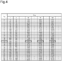
- Fig. 4 is a part of "Table 7.1.7.2.1-1" of NPL 1.
- data communication according to the 3GPP standards is conducted on a codeword basis and a maximum of four layers can be sent with one codeword. For example, if data is to be sent with four layers, it is possible to send the four layers via one codeword or to allocate two layers to one codeword and send the four layers via two codewords.
- the maximum value of the TBS where the above-mentioned number of layers 4 is acquired and the number of bits corresponding to the acquired TBS is a data volume which can be transmitted in 1 [ms].
- the maximum value of the TBS where the above-mentioned number of layers 2 is acquired for each codeword and a total number of bits corresponding to the respectively acquired TBS is a data volume which can be transmitted in 1 [ms].
- Fig. 5 is a part of "Table 7.1.7.2.2-1" of NPL 1.
- Fig. 6 is a part of "Table 7.1.7.2.4-1" of NPL 1.
- Fig. 7 is a part of "Table 7.1.7.2.5-1" of NPL 1.
- the calculation unit 206 calculates 14112000 [bps], which is the maximum available throughput by multiplying 14112 [bits], which is the acquired maximum value of the TBS, by 1000.
- the calculation unit 206 calculates 28336000 [bps], which is the maximum available throughput, by multiplying 28336 [bits], which is the acquired maximum value of the TBS, by 1000.
- the change unit 207 changes the value of the maximum available throughput in the uplink direction to the first threshold value. Moreover, if the maximum available throughput in the downlink direction, which is calculated by the calculation unit 206, exceeds a second threshold value, the change unit 207 changes the value of the maximum available throughput in the downlink direction to the second threshold value.
- the first threshold value and the second threshold value can be set as appropriate according to the respective communication environments for the uplink direction and the downlink direction. Moreover, a threshold value which is different for each application may be set. Furthermore, the value of either the maximum available throughput in the uplink direction or the maximum available throughput in the downlink direction which is calculated by the calculation unit 206 and whichever is larger may be changed to the smaller value. Consequently, it becomes possible to set the values of the maximum available throughput in the uplink and downlink directions to the same smaller value of either of them. Specifically speaking, it becomes possible to control the communication by suppressing the values of the maximum available throughputs in the uplink and downlink directions to the smaller value of either of them.
- the transmission unit 208 sends an alarm for drawing attention to the core network to which the donor base station 30 connects. Either the value of the maximum available throughput in the uplink direction or the value of the maximum available throughput in the downlink direction, whichever is smaller, is used as the maximum available throughput to be compared with the third threshold value.
- the third threshold value may be the same value as, or a different value from, either one of the first threshold value or the second threshold value described above.
- the base station generally allocates the MCS Index and the number of layers, which are largest possible within the range capable of securing the radio quality, to terminals so that as many terminals as possible can be housed at the same time, that is, the occupancy of radio resources (such as frequency and time) per terminal is reduced as much as possible (the radio utilization efficiency becomes maximum).
- the radio quality is not determined, for example, immediately after the connection, it becomes difficult to allocate the MCS Index and the number of layers which maximize the utilization efficiency.
- the MCS Index and the number of layers which maximize the utilization efficiency also change. Therefore, it is preferable that the maximum available throughput should be estimated from regularly obtained throughputs, but not an instantaneous maximum throughput, after observing the MCS Index and the number of layers which change from moment to moment to a certain degree.
- the MCS and the number of layers in the uplink direction which are decided at the donor base station 30 on the basis of the communication status in the uplink direction, and the MCS and the number of layers in the downlink direction which are decided at the donor base station 30 on the basis of the communication status in the downlink direction are received from the donor base station 30;
- the maximum available throughput in the uplink direction is calculated on the basis of the received MCS and the received number of layers in the uplink direction and the maximum number of resource blocks which can be allocated by the donor base station 30, and the maximum available throughput in the downlink direction is calculated on the basis of the received MCS and the received number of layers in the downlink direction and the maximum number of resource blocks which can be allocated by the donor base station 30; and if the calculated maximum available throughput in the uplink direction exceeds the first threshold value, the value of the maximum available throughput in the uplink direction can be changed to the first threshold value; and if the calculated maximum available throughput in the downlink direction exceeds the second threshold value, the
- the communication in the respective uplink and downlink directions can be controlled after setting the maximum available throughput in each of the uplink and downlink directions between the relay apparatus 20 and the donor base station 30 to be within the range not exceeding the threshold value for each of them.
- an appropriate maximum available throughput can be decided when controlling the communication at the relay apparatus 20 capable of relaying the communication between the donor base station 30 and the terminal device 10.
- the voice call service via VoLTE is provided by the mobile communications system 100
- the voice call service is provided by using the communication in the uplink and downlink directions. Therefore, it is an especially effective means, when providing the voice call service, to adjust the maximum available throughputs in the respective uplink and downlink directions in consideration of the communication status in the respective uplink and downlink directions.
- the aforementioned embodiment has described the case where the present invention is applied to the relay apparatus 20 capable of connecting to one donor base station 30 operated by a specified mobile network operator MNO; however, the configuration of the relay apparatus 20 is not limited to this.
- the present invention can be also applied to a relay apparatus capable of simultaneously connecting to donor base stations of different mobile network operators.
- Such a relay apparatus will be explained below in detail as a relay apparatus 20s according to a first variation.
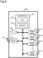
- Fig. 8 illustrates a hardware configuration of the relay apparatus 20s according to the first variation.
- the relay apparatus 20s is a relay apparatus capable of simultaneously connecting to systems operated by different mobile network operators.
- the relay apparatus 20s is configured by including, for example, an access node 22, a plurality of relay nodes 24, an information processing unit 201, and an information storage unit 202.
- the information processing unit 201 includes a central processing unit (CPU) 2011 and a memory 2012 in the same manner as the information processing unit 201 for the relay apparatus 20 according to the aforementioned embodiment and functionally implements the relay apparatus 20s by execution of a computer software program, which is stored in the memory 2012, by the CPU 2011.
- CPU central processing unit
- the plurality of relay nodes 24 respectively establish backhaul communication paths BH with different donor cell base stations 30 as illustrated in Fig. 9 .
- the terminal devices 10, the relay nodes 24, the backhaul communication paths BH, and the donor cell base stations 30 are managed by being respectively associated with identification information ID for identifying the relevant mobile network operator.
- the identification information ID is unique information for identifying the relevant mobile network operator and, for example, a PLMN (Public Land Mobile Network) number which is a land mobile network number can be used.
- the PLMN number consists of a 3-digit country number and a 2 or 3-digit network number for identifying the relevant network operator.
- the identification information ID may be assigned according to a system other than the PLMN number.
- the representation will be hereinafter simplified and the different mobile network operators will be identified with lower-case alphabet characters, for example, by indicating the identification information of a mobile network operator x as IDx.
- a relay node 24a establishes a backhaul communication path BHa with a donor cell base station 30a associated with identification information IDa for identifying a mobile network operator a, and a terminal device 10a which is connected to the access node 22 is in a state capable of communicating with the donor cell base station 30a.
- a relay node 24b establishes a backhaul communication path BHb with a donor cell base station 30b associated with identification information IDb for identifying a mobile network operator b, and a terminal device 10b which is connected to the access node 22 is in a state capable of communicating with the donor cell base station 30b.
- a relay node 24c establishes a backhaul communication path BHc with a donor cell base station 30c associated with identification information IDc for identifying a mobile network operator c, and a terminal device 10c which is connected to the access node 22 is in a state capable of communicating with the donor cell base station 30c.
- the relay apparatus 20s includes a plurality of relay nodes 24x capable of establishing a backhaul communication path BHx with each arbitrary mobile network operator x who is permitted to do business.
- the relay apparatus 20s relays uplink data which is sent from the terminal device 10x to the donor cell base station 30x as described below.
- the information processing unit 201 supplies the uplink data, which has been provided from the access node 22, to the relay node 24x which establishes the backhaul communication path BHx associated with the identification information IDx included in that uplink data. Specifically speaking, the information processing unit 201 refers to the identification information IDx included in the uplink data. Subsequently, a block(s) of packet data to which the referenced identification information IDx is assigned is supplied to the relevant relay node 24x. As a result of this operation, integrated data CD is sorted into divided data SDx for each mobile network operator.
- the information processing unit 201 writes blocks of the packet data to the information storage unit 202 in the order of arrival. Then, the information processing unit 201 reads the blocks of the packet data in the written order by using an FIFO (First-in First-out) function of the information storage unit 202. Subsequently, the information processing unit 201 supplies the read blocks of the packet data, as the divided data SDx sorted for each mobile network operator x on the basis of the identification information IDx, to the relay node 24x. Then, the relay node 24x sends the supplied divided data SDx to the relevant donor cell base station 30x via the backhaul communication path BHx.
- FIFO First-in First-out
- the relay apparatus 20s relays the downlink data sent from the donor cell base station 30x to the terminal device 10x as described below.
- the information processing unit 201 sequentially supplies the downlink data from one or more backhaul communication paths BHx to the access node 22. Specifically speaking, the information processing unit 201 generates the integrated data CD by integrating the packet data, which are received and transferred from the relay node 24x, with respect to each block in the order of arrival. As a result of this operation, the blocks of the packet data individually sent from the respective mobile network operators are integrated.
- Each relay node 24x outputs the blocks of the packet data in the order of arrival. Then, the information processing unit 201 writes the blocks of the packet data to the information storage unit 202 in the output order. Subsequently, the information processing unit 201 reads the blocks of the packet data in the written order by using the FIFO function of the information storage unit 204 and outputs them as the integrated data CD to the access node 22. Then, the access node 22 sequentially sends the blocks of the packet data via a common frequency bandwidth to each terminal device 10x.
- the relay apparatus 20s which is configured as described above controls the communication in the respective uplink and downlink directions after setting the maximum available throughputs in the respective uplink and downlink directions between the relay apparatus 20 and the donor base station 30 with respect to each backhaul communication path BHx established by each relay node 24x.
- the above-described relay apparatus 20s has functions equivalent to the respective functions (the receiving unit 205, the calculation unit 206, the change unit 207, and the transmission unit 208 in Fig. 2 ) possessed by the information processing unit 201 for the relay apparatus 20 according to the embodiment and each of these functions is implemented with respect to each backhaul communication path BHx established by each relay node 24x.
- the respective functions possessed by the information processing unit 201 for the relay apparatus 20s according to the first variation will be specifically explained below.
- the receiving unit 205 receives the MCS and the number of layers in the uplink direction and the MCS and the number of layers in the downlink direction with respect to each backhaul communication path BHx established by each relay node 24x. Moreover, the receiving unit 205 receives the maximum number of resource blocks from the donor base station 30x when connecting to the donor base station 30x.
- the calculation unit 206 calculates the maximum available throughput in the uplink direction and the maximum available throughput in the downlink direction with respect to each backhaul communication path BHx established by each relay node 24x.
- the calculation unit 206 calculates the maximum throughput which can be used in the uplink direction on the basis of a value calculated from a combination of an index corresponding to the MCS in the uplink direction, which is received by the receiving unit 205, and the maximum number of resource blocks, and the number of layers in the uplink direction which is received by the receiving unit 205. Then, the calculation of this maximum throughput is conducted with respect to each backhaul communication path BHx.
- the calculation unit 206 calculates the maximum throughput which can be used in the downlink direction on the basis of a value calculated from a combination of an index corresponding to the MCS in the downlink direction, which is received by the receiving unit 205, and the maximum number of resource blocks, and the number of layers in the downlink direction which is received by the receiving unit 205. Then, the calculation of this maximum throughput is conducted with respect to each backhaul communication path BHx.
- the change unit 207 changes the value of the maximum available throughput in the uplink direction and the value of the maximum available throughput in the downlink direction with respect to each backhaul communication path BHx established by each relay node 24x.
- the change unit 207 changes the value of the maximum available throughput in the uplink direction to the first threshold value. This change processing is then executed for each backhaul communication path BHx. Moreover, if the maximum available throughput in the downlink direction, which is calculated by the calculation unit 206, exceeds a second threshold value, the change unit 207 changes the value of the maximum available throughput in the downlink direction to the second threshold value. This change processing is then executed for each backhaul communication path BHx.
- the first threshold value and the second threshold value are similar to those in the aforementioned embodiment, so an explanation about them is omitted. Moreover, the value of whichever is larger of the maximum available throughputs may be changed to the smaller value in the same manner as in the aforementioned embodiment, so an explanation about that is also omitted.
- the transmission unit 208 compares the maximum available throughput calculated by the calculation unit 206 with a third threshold value with respect to each backhaul communication path BHx established by each relay node 24x. If the maximum available throughput is smaller than the third threshold value, the transmission unit 208 sends an alarm to the core network to which the donor base station 30x connects.
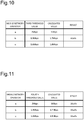
- Fig. 10 shows that the mobile network operators which have established the backhaul communication paths BHx are three mobile network operators "a,” “b,” and “c," their respective third threshold values are “2 Mbs,” “1.9 Mbs,” and “1.6 Mbs,” and the maximum available throughputs which are their respective calculated values are “3 Mbs,” “1.7 Mbs,” and “1.8 Mbs.”
- the calculated value of the mobile network operator "b” becomes smaller than the third threshold value. Therefore, the backhaul communication path BHb for the mobile network operator "b” becomes a target of the alarm.
- the relay apparatus 20s having the plurality of relay nodes 24x for respectively establishing the backhaul communication paths BHx, which are associated with the identification information IDx, with the donor base station 30x associated with the identification information IDx can bring about the advantageous effects similar to those of the aforementioned embodiment.
- the MCS and the number of layers in the uplink direction and the MCS and the number of layers in the downlink direction can be received with respect to each established backhaul communication path BHx; the maximum available throughput in the uplink direction and the maximum available throughput in the downlink direction can be calculated with respect to each established backhaul communication path BHx; and the value of the maximum available throughput in the uplink direction and the value of the maximum available throughput in the downlink direction can be changed with respect to each established backhaul communication path BHx.
- the alarm can be sent to the core network to which the donor base station 30x connects.
- the information processing unit 201 may further include a connection control unit. If the maximum available throughput calculated by the calculation unit 206 is smaller than a fourth threshold value, the connection control unit for the relay apparatus 20 according to the embodiment limits the maximum number of the terminal devices 10 which can connect to the access node 22 on the basis of the maximum available throughput.
- connection control unit for the relay apparatus 20s compares the maximum available throughput calculated by the calculation unit 206 with the fourth threshold value with respect to each backhaul communication path BHx established by the relay node 24x; and if the maximum available throughput is smaller than the fourth threshold value, the maximum number of the terminal devices 10 which can connect to the access node 22 is limited based on the maximum available throughput.
- the fourth threshold value according to the second variation may be set as the same value as, or a different value from, the third threshold value according to the first variation.
- a specific explanation will be provided about a case where the maximum number of the terminal devices 10 which can connect to the access node 22 is limited with the relay apparatus 20s according to the first variation.
- "16 calls” is set as an initial value of the maximum number of the terminal devices 10 which can be set for each mobile network operator and "16 calls” is also set as the maximum number of the terminal devices 10 which can connect to the entire relay apparatus 20s.
- Fig. 11 shows that the mobile network operators which have established the backhaul communication paths BHx are three mobile network operators "a,” “b,” and “c," their respective forth threshold values are “2 Mbs,” “1.9 Mbs,” and “1.6 Mbs,” and the maximum available throughputs which are their respective calculated values are “3 Mbs,” “1.7 Mbs,” and “1.8 Mbs.”
- the calculated value of the mobile network operator "b” becomes smaller than the fourth threshold value. Therefore, the maximum number of the terminal devices 10b for the mobile network operator "b” is limited by being reduced from “16 calls” to "10 calls.”
- the second variation can bring about advantageous effects similar to those of the aforementioned embodiment and the aforementioned first variation; and if the calculated maximum available throughput with respect to each backhaul communication path BHx established by each relay node 24x is smaller than the fourth threshold value, the maximum number of the terminal devices 10 which can connect to the access node 22 can be limited based on the maximum available throughput.
Landscapes
- Engineering & Computer Science (AREA)
- Computer Networks & Wireless Communication (AREA)
- Signal Processing (AREA)
- Mobile Radio Communication Systems (AREA)
Abstract
Description
- The present invention relates to a relay apparatus, communication control method, and program capable of relaying communication between a macro cell base station(s) and a terminal device(s).
- LTE (Long Term Evolution) has been gaining widespread use in place of the third-generation mobile communication system (3G: 3rd Generation) as a standardization standard for radio communication systems. LTE is a telecommunications standard for supporting only packet communications and voices are converted to packets according to VoIP (Voice over Internet Protocol) and sent and received as packets. Particularly, VoIP according to the LTE standard is called VoLTE (Voice over LTE).
-
PTL 1 mentioned below discloses a technology that calculates a maximum available throughput which can be used for communication between a base station and a user apparatus according to LTE. ThisPTL 1 calculates the maximum available throughput on the basis of a CQI (Channel Quality Indicator) report fed back from the user apparatus, which has received a pilot signal sent from the base station in a downlink direction, to the base station. -
PTL 2 mentioned below discloses a technology regarding a femto cell base station for relaying packet communication between a macro cell base station and a mobile unit. -
- PTL 1:
Japanese Patent Application Laid-Open (Kokai) Publication No. 2015-133700 - PTL 2:
Japanese Patent Application Laid-Open (Kokai) Publication No. 2016-171536 - Meanwhile, regarding
PTL 1, the communication between the base station and the user apparatus is controlled on the basis of the maximum available throughput in the downlink direction from the base station to the user apparatus. Therefore, for example, even in the circumstance where the maximum available throughput in an uplink direction becomes smaller than the maximum available throughput in the downlink direction, the communication in the uplink direction will be controlled on the basis of the maximum available throughput in the downlink direction. - When controlling the communication between the relay apparatus like the femto cell base station described in
PTL 2 and the macro cell base station, there is a possibility that the communication quality may degrade if an attempt is made to control the communication on the premise that a throughput which is larger than the actual maximum available throughput can be used. - The present invention was devised in light of the above-described circumstances and it is one of objects to decide an appropriate maximum available throughput when controlling the communication at the relay apparatus capable of relaying the communication between the macro cell base station(s) and the terminal device(s).
- A relay apparatus according to one aspect of the present invention is a relay apparatus capable of relaying communication between a macro cell base station and at least one terminal device, wherein the relay apparatus includes: a receiving unit that receives an MCS (Modulation and Coding Scheme) and the number of layers in an uplink direction, which are decided at a macro cell base station on the basis of a communication status in the uplink direction from a local apparatus to the macro cell base station, and receives an MCS and the number of layers in a downlink direction, which are decided at the macro cell base station on the basis of a communication status in the downlink direction from the macro cell base station to the local apparatus; a calculation unit that calculates a maximum available throughput in the uplink direction on the basis of the received MCS and the received number of layers in the uplink direction and a maximum number of resource blocks which can be allocated by the macro cell base station, and calculates a maximum available throughput in the downlink direction on the basis of the received MCS and the received number of layers in the downlink direction and a maximum number of resource blocks which can be allocated by the macro cell base station; and a change unit that: changes a value of the maximum available throughput in the uplink direction to a first threshold value if the calculated maximum available throughput in the uplink direction exceeds the first threshold value; and changes a value of the maximum available throughput in the downlink direction to a second threshold value if the maximum available throughput in the downlink direction exceeds the second threshold value.
- According to the above-described aspect, the relay apparatus may further include: a plurality of backhaul communication units, each of which establishes a backhaul communication path associated with specified identification information between the relevant backhaul communication unit and the macro cell base station associated with the specified identification information; and a communication control unit that controls communication between the terminal device associated with the specified identification information and the specified backhaul communication path associated with the specified identification information, wherein the receiving unit may receive the MCS and the number of layers in the uplink direction and the MCS and the number of layers in the downlink direction with respect to each established backhaul communication path; wherein the calculation unit may calculate the maximum available throughput in the uplink direction and the maximum available throughput in the downlink direction with respect to each established backhaul communication path; and wherein the change unit may change the value of the maximum available throughput in the uplink direction and the value of the maximum available throughput in the downlink direction with respect to each established backhaul communication path.
- According to the above-described aspect, the calculation unit may calculate a maximum throughput which can be used in the uplink direction on the basis of a value calculated from a combination of an index corresponding to the received MCS in the uplink direction and the maximum number of resource blocks, and the received number of layers in the uplink direction and calculate a maximum throughput which can be used in the downlink direction on the basis of a value calculated from a combination of an index corresponding to the received MCS in the downlink direction and the maximum number of resource blocks, and the received number of layers in the downlink direction.
- According to the above-described aspect, the receiving unit may further receive the maximum number of resource blocks when connecting to the macro cell base station.
- According to the above-described aspect, the communication may be voice calls; and the change unit may change the calculated value of either the maximum available throughput in the uplink direction or the maximum available throughput in the downlink direction, whichever is larger, to a smaller value of either of them.
- According to the above-described aspect, the relay apparatus may further include a transmission unit that sends an alarm to a core network to which the macro cell base station connects when the calculated maximum available throughput is smaller than a third threshold value.
- According to the above-described aspect, the relay apparatus may further include a connection control unit that controls a maximum number of the terminal devices which can be connected when the calculated maximum available throughput is smaller than a fourth threshold value.
- A communication control method according to another aspect of the present invention is a communication control method for controlling communication of a relay apparatus capable of relaying communication between a macro cell base station and at least one terminal device, wherein the communication control method includes: a reception step of receiving an MCS and the number of layers in an uplink direction, which are decided at the macro cell base station on the basis of a communication status in the uplink direction from the relay apparatus to the macro cell base station, and receiving an MCS and the number of layers in a downlink direction, which are decided at the macro cell base station on the basis of a communication status in the downlink direction from the macro cell base station to the relay apparatus; a calculation step of calculating a maximum available throughput in the uplink direction on the basis of the received MCS and the received number of layers in the uplink direction and a maximum number of resource blocks which can be allocated by the macro cell base station, and calculating a maximum available throughput in the downlink direction on the basis of the received MCS and the received number of layers in the downlink direction and a maximum number of resource blocks which can be allocated by the macro cell base station; and a change step of: changing a value of the maximum available throughput in the uplink direction to a first threshold value if the calculated maximum available throughput in the uplink direction exceeds the first threshold value; and changing a value of the maximum available throughput in the downlink direction to a second threshold value if the maximum throughput in the downlink direction exceeds the second threshold value.
- A program according to another aspect of the present invention is a program for causing a computer to function as: a receiving unit that receives an MCS and the number of layers in an uplink direction, which are decided at a macro cell base station on the basis of a communication status in the uplink direction from a relay apparatus, which is capable of relaying communication between the macro cell base station and at least one terminal device, to the macro cell base station, and receives an MCS and the number of layers in a downlink direction, which are decided at the macro cell base station on the basis of a communication status in the downlink direction from the macro cell base station to the relay apparatus; a calculation unit that calculates a maximum available throughput in the uplink direction on the basis of the received MCS and the received number of layers in the uplink direction and a maximum number of resource blocks which can be allocated by the macro cell base station, and calculates a maximum available throughput in the downlink direction on the basis of the received MCS and the received number of layers in the downlink direction and a maximum number of resource blocks which can be allocated by the macro cell base station; and a change unit that: changes a value of the maximum available throughput in the uplink direction to a first threshold value if the calculated maximum available throughput in the uplink direction exceeds the first threshold value; and changes a value of the maximum available throughput in the downlink direction to a second threshold value if the maximum available throughput in the downlink direction exceeds the second threshold value.
- The appropriate maximum available throughput can be decided according to the present invention when controlling the communication at the relay apparatus capable of relaying the communication between the macro cell base station(s) and the terminal device(s).
-
- [
Fig. 1] Fig. 1 is a schematic diagram of a mobile communications system including a relay apparatus according to an embodiment; - [
Fig. 2] Fig. 2 is a functional configuration diagram of the relay apparatus according to the embodiment; - [
Fig. 3] Fig. 3 is a diagram illustrating an example of a table to which the relay apparatus according to the embodiment refers; - [
Fig. 4] Fig. 4 is a diagram illustrating an example of a table to which the relay apparatus according to the embodiment refers; - [
Fig. 5] Fig. 5 is a diagram illustrating an example of a table to which the relay apparatus according to the embodiment refers; - [
Fig. 6] Fig. 6 is a diagram illustrating an example of a table to which the relay apparatus according to the embodiment refers; - [
Fig. 7] Fig. 7 is a diagram illustrating an example of a table to which the relay apparatus according to the embodiment refers; - [
Fig. 8] Fig. 8 is a hardware configuration diagram of a relay apparatus according to a first variation; - [
Fig. 9] Fig. 9 is a schematic diagram for explaining functions of the relay apparatus according to the first variation; - [
Fig. 10] Fig. 10 is a diagram for explaining the functions of the relay apparatus according to the first variation; and - [
Fig. 11] Fig. 11 is a diagram for explaining functions of the relay apparatus according to a second variation. - An embodiment of the present invention will be explained with reference to the drawings. It should be noted that the embodiment explained below is just for illustration and is not intended to exclude applications of various variations or technologies which are not clearly specified below. In other words, the present invention can be implemented in various variations within the range not departing from the gist of the invention. Furthermore, in the descriptions of a series of the drawings, the same or similar reference numerals are assigned to the same or similar parts.
-
Fig. 1 is a configuration diagram of a mobile communications system including a relay apparatus according to an embodiment of the present invention. Amobile communications system 100 is a mobile communications system capable of providing voice communications services illustratively via the VoLTE according to the LTE system standardized in 3GPP and includes a radio network and a core network. The configuration of the radio network and the configuration of the core network will be sequentially explained below. - Referring to
Fig. 1 , themobile communications system 100 includes, as the configuration relating to the radio network,terminal devices 10, arelay apparatus 20, and a donor base station (macro cell base station) 30. Incidentally, the radio network is also called an E-UTRAN (Evolved Universal Terrestrial Radio Access Network) according to the LTE system. - The
terminal device 10 is a mobile portable communications terminal such as a smartphone or a cell phone and is also called UE (User Equipment).Fig. 1 shows:terminal devices 10a which exist in a service area within a cell (communication-enabled range) formed by therelay apparatus 20 and are connected to therelay apparatus 20; and aterminal device 10b which exists in a service area within a cell formed by thedonor base station 30 and is connected to thedonor base station 30. The terminal device(s) 10a and theterminal device 10b will be sometimes collectively referred to as the terminal device(s) 10. - The
relay apparatus 20 is portable, installable, and relocatable and can be installed not only outside, but also indoors. Therelay apparatus 20 is also called a ReNB (Repeater type eNodeB) according to the LTE system and constitutes one node in the radio network. - The
relay apparatus 20 is configured by including anaccess node 22 and arelay node 24. - The
access node 22 is also called a femto base station, establishes radio communication with theterminal device 10a, and provides theterminal device 10a with packet communication services (such as a voice packet communication service and a multimedia service). A radio communication path established between theaccess node 22 and theterminal device 10a is also called an access communication path AC. The cell size of the cell formed by theaccess node 22 is of a smaller scale than that of thedonor base station 30 and constructs a communication area with a radius ranging from several meters to several tens of meters. - The
access node 22 establishes a radio communication path with thedonor base station 30 via therelay node 24. Therelay node 24 is also called CPE (Customer Premises Equipment). The radio communication path is established between therelay node 24 and thedonor base station 30 and is also called a backhaul communication path BH. - Incidentally, the
access node 22 and therelay node 24 may be configured as separate nodes. If they are configured as separate nodes, therelay node 24 serves the role as the relay apparatus according to the present invention. - The
donor base station 30 is also called a Donor eNB (Donor eNodeB) according to the LTE system and establishes a backhaul communication path BH with therelay node 24. Thedonor base station 30 also directly establishes an access communication path AC with theterminal device 10b. Thedonor base station 30 constructs a communication area with a radius ranging from several hundreds of meters to ten-odd kilometers. - Referring to
Fig. 1 , themobile communications system 100 includes, as the configuration relating to the core network, a first core network EPC (Evolved Packet Core) 40, a femto core network (Femto Core Network) 50, and a secondcore network EPC 60. Incidentally, an explanation will be provided by assuming that this embodiment includes the firstcore network EPC 40 and the secondcore network EPC 60; however, the core network EPC may be configured from one core network. - The first
core network EPC 40 connects to, for example, thedonor base station 30 and has functions such as: a function that manages movements of, authenticates, and manages packet communication data path setting processing for the individualterminal devices 10b and therelay node 24 via thedonor base station 30; a function that implements quality management in the radio network; a function that controls call connection for providing mobile communication services and controls the services; and a function as a switching station that receives calls for a contract holder within the radio network or a subscriber during roaming within the radio network from an external network such as theInternet 70. - The
femto core network 50 is a network for performing various kinds of management regarding therelay apparatus 20. Thefemto core network 50 is connected to, for example, a femto OAM (Femto Operations Administration Maintenance) 52 and has a function that operates, manages, and maintains therelay apparatus 20. - The second
core network EPC 60 has, for example: a function that controls call connection for providing the mobile communication services and controls the services; a function as a switching station that receives calls for a contract holder within the radio network or a subscriber during roaming within the radio network from an external network such as theInternet 70; a function that manages movements of, authenticates, and manages packet communication data path setting processing for theindividual terminal devices 10a within the secondcore network EPC 60; and a function that executes communication policy control, such as quality control, and control according to accounting rules. -
Fig. 2 is a functional configuration diagram of the relay apparatus according to the embodiment of the present invention. Referring toFig. 2 , therelay apparatus 20 includes, as a functional configuration, for example, aninformation processing unit 201 that executes information processing for controlling communication between thedonor base station 30 and therelay apparatus 20, and aninformation storage unit 202 that stores, for example, data used to control the communication between thedonor base station 30 and therelay apparatus 20. - The
relay apparatus 20 includes, as a physical configuration, for example, a central processing unit (CPU) and a memory and functionally implements theinformation processing unit 201 by execution of a computer software program by the CPU. Theinformation processing unit 201 illustratively includes a receivingunit 205, acalculation unit 206, achange unit 207, and atransmission unit 208. - The receiving
unit 205 receives an MCS (Modulation and Coding Scheme) which is determined by a set of a modulation method and a coded rate, and the number of layers, which is the number of streams that can be transmitted at the same time, from thedonor base station 30. Illustratively, the MCS can be decided from "0" to "31" and the number of layers can be decided up to a maximum of eight according to the LTE standards. - The MCS and the number of layers are decided by the
donor base station 30 as follows. Thedonor base station 30 decides the MCS and the number of layers in an uplink direction, which is a direction from therelay apparatus 20 to the donor base station 30 (hereinafter referred to the "uplink direction"), on the basis of a communication status in the uplink direction. Thedonor base station 30 decides the MCS and the number of layers in a downlink direction, which is a direction from thedonor base station 30 to the relay apparatus 20 (hereinafter referred to as the "downlink direction"), on the basis of a communication status in the downlink direction. - The receiving
unit 205 receives the maximum number of resource blocks from thedonor base station 30 when connecting to thedonor base station 30. The maximum number of resource blocks is the maximum number of resource blocks which can be allocated by thedonor base station 30 to each bandwidth used for the communication with the relay apparatus 20 (hereinafter also referred to as a "system bandwidth"). Illustratively, if the system bandwidth is 10 MHz, the maximum number of resource blocks becomes "50"; and if the system bandwidth is 15 MHz, the maximum number of resource blocks becomes "75." - Incidentally, the maximum number of resource blocks does not necessarily have to be received from the
donor base station 30. For example, therelay apparatus 20 may retain a table in which the correspondence relationship between the system bandwidth of eachdonor base station 30 and the maximum number of resource blocks is set; and therelay apparatus 20 may acquire the maximum number of resource blocks from the above-described table on the basis of the system bandwidth of the connecteddonor base station 30. - The
calculation unit 206 calculates the maximum available throughput which can be used in the uplink direction or the downlink direction on the basis of the MCS and the number of layers in the uplink direction or the downlink direction, which are received by the receivingunit 205, and the maximum number of resource blocks. - Specifically speaking, the
calculation unit 206 calculates the maximum available throughput which can be used in the uplink direction on the basis of a value calculated from a combination of an index corresponding to the MCS in the uplink direction, which is received by the receivingunit 205, and the maximum number of resource blocks, and the number of layers in the uplink direction, which is received by the receivingunit 205. Furthermore, thecalculation unit 206 calculates the maximum available throughput which can be used in the downlink direction on the basis of a value calculated from a combination between an index corresponding to the MCS in the downlink direction, which is received from the receivingunit 205, and the maximum number of resource blocks, and the number of layers in the downlink direction which is received by the receivingunit 205. - An explanation will be provided below about an example of a procedure executed by the
calculation unit 206 to calculate the maximum available throughput which can be used in the uplink direction or the downlink direction. With this exemplification, an explanation will be provided about a case where thecalculation unit 206 calculates the maximum available throughput by referring to tables illustrated inFig. 3 to Fig. 7 . Each table is stored in theinformation storage unit 202. -
Fig. 3 is a part of "Table 7.1.7.1-1" of "3GPP TS 36.213 V10.12.0 (2014-03) (hereinafter referred to as "NPL 1")." This table is a table that stores the correspondence relationship between IMCS which is an "MCS Index" and ITBS which is a "TBS (Transport Block Size) Index." In this exemplification, the value of the MCS received from thedonor base station 30 is used as the value of IMCS. The TBS is the number of bits which can be transmitted in 1 [TTI] (1 [ms]) and is classified by the index. -
Fig. 4 is a part of "Table 7.1.7.2.1-1" ofNPL 1. This table is a table that stores the maximum value of the TBS where the number of layers = 1, with respect to each combination of ITBS and NPRB, which is the maximum number of resource blocks. - Under this circumstance, if the number of layers = 2 and NPRB≤55, the maximum value of the TBS where the number of layers = 2 is acquired by doubling the value of NPRB and referring to the table in
Fig. 4 . On the other hand, if the number of layers = 2 and NPRB>55, the maximum value of the TBS where the number of layers = 2 is acquired by converting the maximum value of the TBS where the number of layers = 1, which is acquired from the table inFig. 4 , by using the table inFig. 5 . - Moreover, if the number of layers = 3 and NPRB≤36, the maximum value of the TBS where the number of layers = 3 is acquired by tripling the value of NPRB and referring to the table in
Fig. 4 . On the other hand, if the number of layers = 3 and NPRB>36, the maximum value of the TBS where the number of layers = 3 is acquired by converting the maximum value of the TBS where the number of layers = 1, which is acquired from the table inFig. 4 , by using the table inFig. 6 . - Furthermore, if the number of layers = 4 and NPRB≤27, the maximum value of the TBS where the number of layers = 4 is acquired by quadrupling the value of NPRB and referring to the table in
Fig. 4 . On the other hand, if the number of layers = 4 and NPRB>27, the maximum value of the TBS where the number of layers = 4 is acquired by converting the maximum value of the TBS where the number of layers = 1, which is acquired from the table inFig. 4 , by using the table inFig. 7 . - Under this circumstance, data communication according to the 3GPP standards is conducted on a codeword basis and a maximum of four layers can be sent with one codeword. For example, if data is to be sent with four layers, it is possible to send the four layers via one codeword or to allocate two layers to one codeword and send the four layers via two codewords.
- Illustratively, if the four layers are sent via one codeword, the maximum value of the TBS where the above-mentioned number of layers = 4 is acquired and the number of bits corresponding to the acquired TBS is a data volume which can be transmitted in 1 [ms]. Similarly, if two layers are allocated to one codeword and four layers are sent via two codewords, the maximum value of the TBS where the above-mentioned number of layers = 2 is acquired for each codeword and a total number of bits corresponding to the respectively acquired TBS is a data volume which can be transmitted in 1 [ms].
-
Fig. 5 is a part of "Table 7.1.7.2.2-1" ofNPL 1. This table is a table to which the reference is made where the number of layers = 2 and NPRB>55. This table stores the respective values before and after conversion for converting the maximum value of the TAS where the number of layers = 1 which is acquired from the table inFig. 4 , to the maximum value of the TBS where the number of layers = 2. -
Fig. 6 is a part of "Table 7.1.7.2.4-1" ofNPL 1. This table is a table to which the reference is made where the number of layers = 3 and NPRB>36. This table stores the respective values before and after conversion for converting the maximum value of the TAS where the number of layers = 1 which is acquired from the table inFig. 4 , to the maximum value of the TBS where the number of layers = 3. -
Fig. 7 is a part of "Table 7.1.7.2.5-1" ofNPL 1. This table is a table to which the reference is made where the number of layers = 4 and NPRB>27. This table stores the respective values before and after conversion for converting the maximum value of the TAS where the number of layers = 1, which is acquired from the table inFig. 4 , to the maximum value of the TBS where the number of layers = 4. - An explanation will be provided about the respective procedures for calculating the maximum available throughput on the basis of the tables illustrated in
Fig. 3 to Fig. 7 under the respective conditions (1) to (5) exemplified below. Since the maximum available throughput in the uplink direction and the downlink direction can be calculated in the same manner, the following explanation will be provided without specifying either the uplink direction or the downlink direction. - (1) Where the system bandwidth = 10 [MHz], the maximum number of resource blocks (NPRB) = 50, the number of layers = 1, and the MCS Index (IMCS) = 15;
- Firstly, the
calculation unit 206 refers to the table inFig. 3 and identifies ITBS= 14 corresponding to IMCS= 15. - Then, the
calculation unit 206 refers to the table inFig. 4 and acquires 14112 [bit] which is the maximum value of the TBS where the number of layers = 1, on the basis of ITBS= 14 and NPRB= 50. - Subsequently, the
calculation unit 206 calculates 14112000 [bps], which is the maximum available throughput by multiplying 14112 [bits], which is the acquired maximum value of the TBS, by 1000. - (2) Where the system bandwidth = 10 [MHz], the maximum number of resource blocks (NPRB) = 50, the number of layers = 2, and the MCS Index (IMCS) = 15;
- Firstly, the
calculation unit 206 refers to the table inFig. 3 and identifies ITBS= 14 corresponding to IMCS= 15. - Then, since the number of layers = 2 and NPRB≤55, the
calculation unit 206 refers to the table inFig. 4 and acquires 28336 [bits], which is the maximum value of the TBS where the number of layers = 2, on the basis of 100, which is twice as much as ITBS= 14 and NPRB= 50. - Subsequently, the
calculation unit 206 calculates 28336000 [bps], which is the maximum available throughput, by multiplying 28336 [bits], which is the acquired maximum value of the TBS, by 1000. - (3) Where the system bandwidth = 15 [MHz], the maximum number of resource blocks (NPRB) = 75, the number of layers = 2, and the MCS Index (IMCS) = 15;
- Firstly, the
calculation unit 206 refers to the table inFig. 3 and identifies ITBS= 14 corresponding to IMCS= 15. - Then, since the number of layers = 2 and NPRB>55, the
calculation unit 206 refers to the table inFig. 4 and acquires 21384 [bits], which is the maximum value of the TBS where the number of layers = 1, from ITBS= 14 and NPRB= 75. - Then, since the number of layers = 2 and NPRB>55, the
calculation unit 206 refers to the table inFig. 5 and acquires 42368 [bits] as the maximum value of the TBS where the number of layers = 2 corresponding to 21384 [bits], which is the maximum value of the TBS where the number of layers = 1. - Subsequently, the
calculation unit 206 calculates 42368000 [bps], which is the maximum available throughput by multiplying 42368 [bits], which is the maximum value of the TBS where the acquired number of layers = 2, by 1000. - (4) Where the system bandwidth = 10 [MHz], the maximum number of resource blocks (NPRB) = 50, the number of layers = 3, and the MCS Index (IMCS) = 15;
- Firstly, the
calculation unit 206 refers to the table inFig. 3 and identifies ITBS= 14 corresponding to IMCS= 15. - Then, since the number of layers = 3 and NPRB>36, the
calculation unit 206 refers to the table inFig. 4 and acquires 14112 [bits], which is the maximum value of the TBS where the number of layers = 1, from ITBS= 14 and NPRB= 50. - Then, since the number of layers = 3 and NPRB>36, the
calculation unit 206 refers to the table inFig. 6 and acquires 42368 [bits] as the maximum value of the TBS where the number of layers = 3 corresponding to 14112 [bits] which is the maximum value of the TBS where the number of layers = 1. - Subsequently, the
calculation unit 206 calculates 42368000 [bps], which is the maximum available throughput by multiplying 42368 [bits], which is the maximum value of the TBS where the acquired number of layers =3, by 1000. - (5) Where the system bandwidth = 10 [MHz], the maximum number of resource blocks (NPRB) = 50, the number of layers = 4, and the MCS Index (IMCS) = 15;
- Firstly, the
calculation unit 206 refers to the table inFig. 3 and identifies ITBS= 14 corresponding to IMCS= 15. - Then, since the number of layers = 4 and NPRB>27, the
calculation unit 206 refers to the table inFig. 4 and acquires 14112 [bits], which is the maximum value of the TBS where the number of layers = 1, from ITBS= 14 and NPRB=50. - Then, since the number of layers = 4 and NPRB>27, the
calculation unit 206 refers to the table inFig. 7 and acquires 57336 [bits] as the maximum value of the TBS where the number of layers = 4 corresponding to 14112 [bits], which is the maximum value of the TBS where the number of layers = 1. - Subsequently, the
calculation unit 206 calculates 57336000 [bps], which is the maximum available throughput by multiplying 57336 [bits], which is the maximum value of the TBS where the acquired number of layers =4, by 1000. - Referring back to the explanation of
Fig. 2 , if the maximum available throughput in the uplink direction, which is calculated by thecalculation unit 206, exceeds a first threshold value, thechange unit 207 changes the value of the maximum available throughput in the uplink direction to the first threshold value. Moreover, if the maximum available throughput in the downlink direction, which is calculated by thecalculation unit 206, exceeds a second threshold value, thechange unit 207 changes the value of the maximum available throughput in the downlink direction to the second threshold value. - The first threshold value and the second threshold value can be set as appropriate according to the respective communication environments for the uplink direction and the downlink direction. Moreover, a threshold value which is different for each application may be set. Furthermore, the value of either the maximum available throughput in the uplink direction or the maximum available throughput in the downlink direction which is calculated by the
calculation unit 206 and whichever is larger may be changed to the smaller value. Consequently, it becomes possible to set the values of the maximum available throughput in the uplink and downlink directions to the same smaller value of either of them. Specifically speaking, it becomes possible to control the communication by suppressing the values of the maximum available throughputs in the uplink and downlink directions to the smaller value of either of them. As a result, for example, as stated in the aforementioned section of "SOLUTION TO PROBLEM," it becomes possible to reliably avoid the situation where the communication is controlled on the premise that the throughput larger than the actual maximum available throughput can be used. This is particularly effective for the voice call service which is provided by using the communication in the uplink and downlink directions. - If the maximum available throughput calculated by the
calculation unit 206 is smaller than a third threshold value, thetransmission unit 208 sends an alarm for drawing attention to the core network to which thedonor base station 30 connects. Either the value of the maximum available throughput in the uplink direction or the value of the maximum available throughput in the downlink direction, whichever is smaller, is used as the maximum available throughput to be compared with the third threshold value. The third threshold value may be the same value as, or a different value from, either one of the first threshold value or the second threshold value described above. - Under this circumstance, the base station generally allocates the MCS Index and the number of layers, which are largest possible within the range capable of securing the radio quality, to terminals so that as many terminals as possible can be housed at the same time, that is, the occupancy of radio resources (such as frequency and time) per terminal is reduced as much as possible (the radio utilization efficiency becomes maximum). However, for example, if the radio quality is not determined, for example, immediately after the connection, it becomes difficult to allocate the MCS Index and the number of layers which maximize the utilization efficiency. Moreover, since the radio quality changes from moment to moment due to the congestion status of surrounding base stations, the MCS Index and the number of layers which maximize the utilization efficiency also change. Therefore, it is preferable that the maximum available throughput should be estimated from regularly obtained throughputs, but not an instantaneous maximum throughput, after observing the MCS Index and the number of layers which change from moment to moment to a certain degree.
- According to the above-described embodiment of the present invention, the MCS and the number of layers in the uplink direction which are decided at the
donor base station 30 on the basis of the communication status in the uplink direction, and the MCS and the number of layers in the downlink direction which are decided at thedonor base station 30 on the basis of the communication status in the downlink direction are received from thedonor base station 30; the maximum available throughput in the uplink direction is calculated on the basis of the received MCS and the received number of layers in the uplink direction and the maximum number of resource blocks which can be allocated by thedonor base station 30, and the maximum available throughput in the downlink direction is calculated on the basis of the received MCS and the received number of layers in the downlink direction and the maximum number of resource blocks which can be allocated by thedonor base station 30; and if the calculated maximum available throughput in the uplink direction exceeds the first threshold value, the value of the maximum available throughput in the uplink direction can be changed to the first threshold value; and if the calculated maximum available throughput in the downlink direction exceeds the second threshold value, the value of the maximum available throughput in the downlink direction can be changed to the second threshold value. - Consequently, the communication in the respective uplink and downlink directions can be controlled after setting the maximum available throughput in each of the uplink and downlink directions between the
relay apparatus 20 and thedonor base station 30 to be within the range not exceeding the threshold value for each of them. - Therefore, an appropriate maximum available throughput can be decided when controlling the communication at the
relay apparatus 20 capable of relaying the communication between thedonor base station 30 and theterminal device 10. - Under this circumstance, when the voice call service via VoLTE is provided by the
mobile communications system 100, the voice call service is provided by using the communication in the uplink and downlink directions. Therefore, it is an especially effective means, when providing the voice call service, to adjust the maximum available throughputs in the respective uplink and downlink directions in consideration of the communication status in the respective uplink and downlink directions. - The present invention has been described by referring to the embodiment as described above; however, it should not be understood that the description and the drawings which constitute part of this disclosure limit this invention. This disclosure should make various substitute embodiments, examples, and operation technologies obvious for those skilled in the art.
- The aforementioned embodiment has described the case where the present invention is applied to the
relay apparatus 20 capable of connecting to onedonor base station 30 operated by a specified mobile network operator MNO; however, the configuration of therelay apparatus 20 is not limited to this. For example, the present invention can be also applied to a relay apparatus capable of simultaneously connecting to donor base stations of different mobile network operators. Such a relay apparatus will be explained below in detail as arelay apparatus 20s according to a first variation. -
Fig. 8 illustrates a hardware configuration of therelay apparatus 20s according to the first variation. Therelay apparatus 20s is a relay apparatus capable of simultaneously connecting to systems operated by different mobile network operators. Therelay apparatus 20s is configured by including, for example, anaccess node 22, a plurality ofrelay nodes 24, aninformation processing unit 201, and aninformation storage unit 202. Theinformation processing unit 201 includes a central processing unit (CPU) 2011 and amemory 2012 in the same manner as theinformation processing unit 201 for therelay apparatus 20 according to the aforementioned embodiment and functionally implements therelay apparatus 20s by execution of a computer software program, which is stored in thememory 2012, by theCPU 2011. - Functions of the
relay apparatus 20s according to the first variation will be explained with reference toFig. 9 . The plurality ofrelay nodes 24 respectively establish backhaul communication paths BH with different donorcell base stations 30 as illustrated inFig. 9 . Theterminal devices 10, therelay nodes 24, the backhaul communication paths BH, and the donorcell base stations 30 are managed by being respectively associated with identification information ID for identifying the relevant mobile network operator. - The identification information ID is unique information for identifying the relevant mobile network operator and, for example, a PLMN (Public Land Mobile Network) number which is a land mobile network number can be used. The PLMN number consists of a 3-digit country number and a 2 or 3-digit network number for identifying the relevant network operator. However, the identification information ID may be assigned according to a system other than the PLMN number. The representation will be hereinafter simplified and the different mobile network operators will be identified with lower-case alphabet characters, for example, by indicating the identification information of a mobile network operator x as IDx.
- Referring to
Fig. 9 , arelay node 24a establishes a backhaul communication path BHa with a donorcell base station 30a associated with identification information IDa for identifying a mobile network operator a, and aterminal device 10a which is connected to theaccess node 22 is in a state capable of communicating with the donorcell base station 30a. - Moreover, a
relay node 24b establishes a backhaul communication path BHb with a donorcell base station 30b associated with identification information IDb for identifying a mobile network operator b, and aterminal device 10b which is connected to theaccess node 22 is in a state capable of communicating with the donorcell base station 30b. - Furthermore, a
relay node 24c establishes a backhaul communication path BHc with a donorcell base station 30c associated with identification information IDc for identifying a mobile network operator c, and aterminal device 10c which is connected to theaccess node 22 is in a state capable of communicating with the donorcell base station 30c. - Consequently, the
relay apparatus 20s according to the first variation includes a plurality ofrelay nodes 24x capable of establishing a backhaul communication path BHx with each arbitrary mobile network operator x who is permitted to do business. - The
relay apparatus 20s relays uplink data which is sent from theterminal device 10x to the donorcell base station 30x as described below. Theinformation processing unit 201 supplies the uplink data, which has been provided from theaccess node 22, to therelay node 24x which establishes the backhaul communication path BHx associated with the identification information IDx included in that uplink data. Specifically speaking, theinformation processing unit 201 refers to the identification information IDx included in the uplink data. Subsequently, a block(s) of packet data to which the referenced identification information IDx is assigned is supplied to therelevant relay node 24x. As a result of this operation, integrated data CD is sorted into divided data SDx for each mobile network operator. - The procedure for sorting the above-mentioned the divided data SDx will be explained in detail. The
information processing unit 201 writes blocks of the packet data to theinformation storage unit 202 in the order of arrival. Then, theinformation processing unit 201 reads the blocks of the packet data in the written order by using an FIFO (First-in First-out) function of theinformation storage unit 202. Subsequently, theinformation processing unit 201 supplies the read blocks of the packet data, as the divided data SDx sorted for each mobile network operator x on the basis of the identification information IDx, to therelay node 24x. Then, therelay node 24x sends the supplied divided data SDx to the relevant donorcell base station 30x via the backhaul communication path BHx. - The
relay apparatus 20s relays the downlink data sent from the donorcell base station 30x to theterminal device 10x as described below. Theinformation processing unit 201 sequentially supplies the downlink data from one or more backhaul communication paths BHx to theaccess node 22. Specifically speaking, theinformation processing unit 201 generates the integrated data CD by integrating the packet data, which are received and transferred from therelay node 24x, with respect to each block in the order of arrival. As a result of this operation, the blocks of the packet data individually sent from the respective mobile network operators are integrated. - The procedure for generating the above-mentioned integrated data CD will be explained in detail. Each
relay node 24x outputs the blocks of the packet data in the order of arrival. Then, theinformation processing unit 201 writes the blocks of the packet data to theinformation storage unit 202 in the output order. Subsequently, theinformation processing unit 201 reads the blocks of the packet data in the written order by using the FIFO function of the information storage unit 204 and outputs them as the integrated data CD to theaccess node 22. Then, theaccess node 22 sequentially sends the blocks of the packet data via a common frequency bandwidth to eachterminal device 10x. - The
relay apparatus 20s which is configured as described above controls the communication in the respective uplink and downlink directions after setting the maximum available throughputs in the respective uplink and downlink directions between therelay apparatus 20 and thedonor base station 30 with respect to each backhaul communication path BHx established by eachrelay node 24x. - The above-described
relay apparatus 20s has functions equivalent to the respective functions (the receivingunit 205, thecalculation unit 206, thechange unit 207, and thetransmission unit 208 inFig. 2 ) possessed by theinformation processing unit 201 for therelay apparatus 20 according to the embodiment and each of these functions is implemented with respect to each backhaul communication path BHx established by eachrelay node 24x. The respective functions possessed by theinformation processing unit 201 for therelay apparatus 20s according to the first variation will be specifically explained below. - The receiving
unit 205 receives the MCS and the number of layers in the uplink direction and the MCS and the number of layers in the downlink direction with respect to each backhaul communication path BHx established by eachrelay node 24x. Moreover, the receivingunit 205 receives the maximum number of resource blocks from thedonor base station 30x when connecting to thedonor base station 30x. - The
calculation unit 206 calculates the maximum available throughput in the uplink direction and the maximum available throughput in the downlink direction with respect to each backhaul communication path BHx established by eachrelay node 24x. - Specifically speaking, the
calculation unit 206 calculates the maximum throughput which can be used in the uplink direction on the basis of a value calculated from a combination of an index corresponding to the MCS in the uplink direction, which is received by the receivingunit 205, and the maximum number of resource blocks, and the number of layers in the uplink direction which is received by the receivingunit 205. Then, the calculation of this maximum throughput is conducted with respect to each backhaul communication path BHx. Moreover, thecalculation unit 206 calculates the maximum throughput which can be used in the downlink direction on the basis of a value calculated from a combination of an index corresponding to the MCS in the downlink direction, which is received by the receivingunit 205, and the maximum number of resource blocks, and the number of layers in the downlink direction which is received by the receivingunit 205. Then, the calculation of this maximum throughput is conducted with respect to each backhaul communication path BHx. - Since specific procedures for calculating the maximum available throughput which can be used in the uplink direction or the downlink direction are similar to those in the aforementioned embodiment, an explanation about them is omitted.
- The
change unit 207 changes the value of the maximum available throughput in the uplink direction and the value of the maximum available throughput in the downlink direction with respect to each backhaul communication path BHx established by eachrelay node 24x. - Specifically speaking, if the maximum available throughput in the uplink direction, which is calculated by the
calculation unit 206, exceeds a first threshold value, thechange unit 207 changes the value of the maximum available throughput in the uplink direction to the first threshold value. This change processing is then executed for each backhaul communication path BHx. Moreover, if the maximum available throughput in the downlink direction, which is calculated by thecalculation unit 206, exceeds a second threshold value, thechange unit 207 changes the value of the maximum available throughput in the downlink direction to the second threshold value. This change processing is then executed for each backhaul communication path BHx. - The first threshold value and the second threshold value are similar to those in the aforementioned embodiment, so an explanation about them is omitted. Moreover, the value of whichever is larger of the maximum available throughputs may be changed to the smaller value in the same manner as in the aforementioned embodiment, so an explanation about that is also omitted.
- The
transmission unit 208 compares the maximum available throughput calculated by thecalculation unit 206 with a third threshold value with respect to each backhaul communication path BHx established by eachrelay node 24x. If the maximum available throughput is smaller than the third threshold value, thetransmission unit 208 sends an alarm to the core network to which thedonor base station 30x connects. The value of either the maximum available throughput in the uplink direction or the maximum available throughput in the downlink direction, whichever is smaller, is used as the maximum available throughput to be compared with the third threshold value. - Referring to
Fig. 10 , the function that sends the alarm will be specifically explained.Fig. 10 shows that the mobile network operators which have established the backhaul communication paths BHx are three mobile network operators "a," "b," and "c," their respective third threshold values are "2 Mbs," "1.9 Mbs," and "1.6 Mbs," and the maximum available throughputs which are their respective calculated values are "3 Mbs," "1.7 Mbs," and "1.8 Mbs." In this case, the calculated value of the mobile network operator "b" becomes smaller than the third threshold value. Therefore, the backhaul communication path BHb for the mobile network operator "b" becomes a target of the alarm. - According to the first variation, the
relay apparatus 20s having the plurality ofrelay nodes 24x for respectively establishing the backhaul communication paths BHx, which are associated with the identification information IDx, with thedonor base station 30x associated with the identification information IDx can bring about the advantageous effects similar to those of the aforementioned embodiment. Specifically speaking, the MCS and the number of layers in the uplink direction and the MCS and the number of layers in the downlink direction can be received with respect to each established backhaul communication path BHx; the maximum available throughput in the uplink direction and the maximum available throughput in the downlink direction can be calculated with respect to each established backhaul communication path BHx; and the value of the maximum available throughput in the uplink direction and the value of the maximum available throughput in the downlink direction can be changed with respect to each established backhaul communication path BHx. - Moreover, according to the first variation, if the maximum available throughput calculated with respect to each backhaul communication path BHx established by each
relay node 24x is smaller than the third threshold value, the alarm can be sent to the core network to which thedonor base station 30x connects. - Regarding the
relay apparatus 20 according to the aforementioned embodiment and therelay apparatus 20s according to the first variation, theinformation processing unit 201 may further include a connection control unit. If the maximum available throughput calculated by thecalculation unit 206 is smaller than a fourth threshold value, the connection control unit for therelay apparatus 20 according to the embodiment limits the maximum number of theterminal devices 10 which can connect to theaccess node 22 on the basis of the maximum available throughput. On the other hand, the connection control unit for therelay apparatus 20s according to the first variation compares the maximum available throughput calculated by thecalculation unit 206 with the fourth threshold value with respect to each backhaul communication path BHx established by therelay node 24x; and if the maximum available throughput is smaller than the fourth threshold value, the maximum number of theterminal devices 10 which can connect to theaccess node 22 is limited based on the maximum available throughput. - The value of either the maximum available throughput in the uplink direction or the maximum available throughput in the downlink direction, whichever is smaller, is used as the maximum available throughput to be compared with the fourth threshold value. Moreover, the fourth threshold value according to the second variation may be set as the same value as, or a different value from, the third threshold value according to the first variation.
- Referring to
Fig. 11 , a specific explanation will be provided about a case where the maximum number of theterminal devices 10 which can connect to theaccess node 22 is limited with therelay apparatus 20s according to the first variation. In the example inFig. 11 , it is assumed that "16 calls" is set as an initial value of the maximum number of theterminal devices 10 which can be set for each mobile network operator and "16 calls" is also set as the maximum number of theterminal devices 10 which can connect to theentire relay apparatus 20s. -
Fig. 11 shows that the mobile network operators which have established the backhaul communication paths BHx are three mobile network operators "a," "b," and "c," their respective forth threshold values are "2 Mbs," "1.9 Mbs," and "1.6 Mbs," and the maximum available throughputs which are their respective calculated values are "3 Mbs," "1.7 Mbs," and "1.8 Mbs." In this case, the calculated value of the mobile network operator "b" becomes smaller than the fourth threshold value. Therefore, the maximum number of theterminal devices 10b for the mobile network operator "b" is limited by being reduced from "16 calls" to "10 calls." - The second variation can bring about advantageous effects similar to those of the aforementioned embodiment and the aforementioned first variation; and if the calculated maximum available throughput with respect to each backhaul communication path BHx established by each
relay node 24x is smaller than the fourth threshold value, the maximum number of theterminal devices 10 which can connect to theaccess node 22 can be limited based on the maximum available throughput. - The aforementioned embodiment, the first variation, and the second variation have been explained by exemplifying the mobile communications systems according to the LTE standards; however, the invention is not limited to these examples and the present invention can be also applied to other telecommunications standards and telecommunications standards which may be set in the future.
-
- 10
- terminal device(s)
- 20
- relay apparatus
- 22
- access node
- 24
- relay node(s)
- 30
- donor base station (macro cell base station)
- 40
- first core network EPC
- 50
- femto core network
- 60
- second core network EPC
- 100
- mobile communications system
- 201
- information processing unit
- 202
- information storage unit
- 205
- receiving unit
- 206
- calculation unit
- 207
- selection unit
- 208
- transmission unit
Claims (9)
- A relay apparatus capable of relaying communication between a macro cell base station and at least one terminal device, the relay apparatus comprising:a receiving unit that receives an MCS (Modulation and Coding Scheme) and the number of layers in an uplink direction, which are decided at a macro cell base station on the basis of a communication status in the uplink direction from a local apparatus to the macro cell base station, and receives an MCS and the number of layers in a downlink direction, which are decided at the macro cell base station on the basis of a communication status in the downlink direction from the macro cell base station to the local apparatus;a calculation unit that calculates a maximum available throughput in the uplink direction on the basis of the received MCS and the received number of layers in the uplink direction and a maximum number of resource blocks which can be allocated by the macro cell base station, and calculates a maximum available throughput in the downlink direction on the basis of the received MCS and the received number of layers in the downlink direction and a maximum number of resource blocks which can be allocated by the macro cell base station; anda change unit that: changes a value of the maximum available throughput in the uplink direction to a first threshold value if the calculated maximum available throughput in the uplink direction exceeds the first threshold value; and changes a value of the maximum available throughput in the downlink direction to a second threshold value if the maximum available throughput in the downlink direction exceeds the second threshold value.
- The relay apparatus according to claim 1, further comprising:a plurality of relay nodes, each of which establishes a backhaul communication path associated with specified identification information between the relevant relay node and the macro cell base station associated with the specified identification information; and an information processing unit that controls communication between the terminal device associated with the specified identification information and the specified backhaul communication path associated with the specified identification information,wherein the receiving unit receives the MCS and the number of layers in the uplink direction and the MCS and the number of layers in the downlink direction with respect to each established backhaul communication path;wherein the calculation unit calculates the maximum available throughput in the uplink direction and the maximum available throughput in the downlink direction with respect to each established backhaul communication path; andwherein the change unit changes the value of the maximum available throughput in the uplink direction and the value of the maximum available throughput in the downlink direction with respect to each established backhaul communication path.
- The relay apparatus according to claim 1 or 2,
wherein the calculation unit calculates a maximum throughput which can be used in the uplink direction on the basis of a value calculated from a combination of an index corresponding to the received MCS in the uplink direction and the maximum number of resource blocks, and the received number of layers in the uplink direction, and calculates a maximum throughput which can be used in the downlink direction on the basis of a value calculated from a combination of an index corresponding to the received MCS in the downlink direction and the maximum number of resource blocks, and the received number of layers in the downlink direction. - The relay apparatus according to any one of claims 1 to 3,
wherein the receiving unit further receives the maximum number of resource blocks when connecting to the macro cell base station. - The relay apparatus according to any one of claims 1 to 4,
wherein the communication is voice calls; and
wherein the change unit changes the calculated value of either the maximum available throughput in the uplink direction or the maximum available throughput in the downlink direction, whichever is larger, to a smaller value of either of them. - The relay apparatus according to any one of claims 1 to 5, further comprising a transmission unit that sends an alarm to a core network to which the macro cell base station connects when the calculated maximum available throughput is smaller than a third threshold value.
- The relay apparatus according to any one of claims 1 to 6, further comprising a connection control unit that controls a maximum number of the terminal devices which can be connected, when the calculated maximum available throughput is smaller than a fourth threshold value.
- A communication control method for controlling communication of a relay apparatus capable of relaying communication between a macro cell base station and at least one terminal device,
the communication control method comprising:a reception step of receiving an MCS and the number of layers in an uplink direction, which are decided at a macro cell base station on the basis of a communication status in the uplink direction from the relay apparatus to the macro cell base station, and receiving the MCS and the number of layers in a downlink direction, which are decided at the macro cell base station on the basis of a communication status in the downlink direction from the macro cell base station to the relay apparatus;a calculation step of calculating a maximum available throughput in the uplink direction on the basis of the received MCS and the received number of layers in the uplink direction and a maximum number of resource blocks which can be allocated by the macro cell base station, and calculating a maximum available throughput in the downlink direction on the basis of the received MCS and the received number of layers in the downlink direction and a maximum number of resource blocks which can be allocated by the macro cell base station; anda change step of: changing a value of the maximum available throughput in the uplink direction to a first threshold value if the calculated maximum available throughput in the uplink direction exceeds the first threshold value; and changing a value of the maximum available throughput in the downlink direction to a second threshold value if the maximum available throughput in the downlink direction exceeds the second threshold value. - A program for causing a computer to function as:a receiving unit that receives an MCS and the number of layers in an uplink direction, which are decided at a macro cell base station on the basis of a communication status in the uplink direction from a relay apparatus, which is capable of relaying communication between the macro cell base station and at least one terminal device, to the macro cell base station, and receives an MCS and the number of layers in a downlink direction, which are decided at the macro cell base station on the basis of a communication status in the downlink direction from the macro cell base station to the relay apparatus;a calculation unit that calculates a maximum available throughput in the uplink direction on the basis of the received MCS and the received number of layers in the uplink direction and a maximum number of resource blocks which can be allocated by the macro cell base station, and calculates a maximum available throughput in the downlink direction on the basis of the received MCS and the received number of layers in the downlink direction and a maximum number of resource blocks which can be allocated by the macro cell base station; anda change unit that: changes a value of the maximum available throughput in the uplink direction to a first threshold value if the calculated maximum available throughput in the uplink direction exceeds the first threshold value; and changes a value of the maximum available throughput in the downlink direction to a second threshold value if the maximum available throughput in the downlink direction exceeds the second threshold value.
Applications Claiming Priority (2)
| Application Number | Priority Date | Filing Date | Title |
|---|---|---|---|
| JP2018195833 | 2018-10-17 | ||
| PCT/JP2019/020922 WO2020079880A1 (en) | 2018-10-17 | 2019-05-27 | Relay device, communication control method, and program |
Publications (1)
| Publication Number | Publication Date |
|---|---|
| EP3860211A1 true EP3860211A1 (en) | 2021-08-04 |
Family
ID=70284479
Family Applications (1)
| Application Number | Title | Priority Date | Filing Date |
|---|---|---|---|
| EP19874122.5A Withdrawn EP3860211A1 (en) | 2018-10-17 | 2019-05-27 | Relay device, communication control method, and program |
Country Status (3)
| Country | Link |
|---|---|
| EP (1) | EP3860211A1 (en) |
| JP (1) | JP7087104B2 (en) |
| WO (1) | WO2020079880A1 (en) |
Family Cites Families (3)
| Publication number | Priority date | Publication date | Assignee | Title |
|---|---|---|---|---|
| US9179355B2 (en) | 2014-01-09 | 2015-11-03 | Apple Inc. | Cell utilization estimation by a wireless device |
| JP6025892B2 (en) | 2015-03-13 | 2016-11-16 | ソフトバンク株式会社 | Mobile communication system |
| JP6677618B2 (en) * | 2016-09-30 | 2020-04-08 | ソフトバンク株式会社 | Software update method and software update server for wireless device |
-
2019
- 2019-05-27 WO PCT/JP2019/020922 patent/WO2020079880A1/en not_active Ceased
- 2019-05-27 EP EP19874122.5A patent/EP3860211A1/en not_active Withdrawn
- 2019-05-27 JP JP2020552510A patent/JP7087104B2/en active Active
Also Published As
| Publication number | Publication date |
|---|---|
| WO2020079880A1 (en) | 2020-04-23 |
| JP7087104B2 (en) | 2022-06-20 |
| JPWO2020079880A1 (en) | 2021-09-09 |
Similar Documents
| Publication | Publication Date | Title |
|---|---|---|
| RU2432696C2 (en) | Method for efficient provision of scheduling information in wireless telecommunication system | |
| RU2566358C2 (en) | Repeater, repeating method, wireless communication system, basic station and wireless communication device | |
| US7917149B2 (en) | System and method for reusing wireless resources in a wireless network | |
| US8767614B2 (en) | Reporting buffering information | |
| US8489090B2 (en) | Aircraft wireless communication system | |
| US9894669B2 (en) | Quality of service enhancement for wireless relay networks | |
| CN116235542B (en) | Routing method, device and system | |
| CN104869527A (en) | Method for data transmission and equipment thereof | |
| CN106254556A (en) | A kind of vehicular ad hoc network gateway device | |
| US20160156485A1 (en) | Tunnel establishment method and apparatus | |
| EP2993936A1 (en) | Adaptive uplink coordinated multipoint communication for backhaul | |
| US20190372636A1 (en) | Relay apparatus and relay method | |
| US9813341B1 (en) | Systems and methods for routing data traffic based on network conditions | |
| US20180279205A1 (en) | Relay apparatus and relay method | |
| US20150304970A1 (en) | Method for enabling lawful interception in a telecommunications network, user equipment for enabling lawful interception in a telecommunications network, base transceiver station for enabling lawful interception in a telecommunications network, program and computer program product | |
| US9572064B2 (en) | Systems and methods for scheduling transmissions from an access node | |
| US10531337B2 (en) | Communication control system, communication control method, program, and relay apparatus | |
| JP7087104B2 (en) | Relay device, communication control method and program | |
| CN119945920A (en) | Network analysis method and device | |
| US10129175B1 (en) | Systems and methods for performing carrier aggregation based on subframe configuration | |
| EP3114868B1 (en) | Methods and devices for managing connectivity for a service | |
| US9560545B1 (en) | Systems and methods for managing communication between an access node and a relay node | |
| US10390330B2 (en) | Methods, wireless device, radio base station and second network node for managing EPS bearer | |
| CN102474754B (en) | The improvement of uplink resource distributes | |
| CN113259986A (en) | Transmission method and network equipment |
Legal Events
| Date | Code | Title | Description |
|---|---|---|---|
| STAA | Information on the status of an ep patent application or granted ep patent |
Free format text: STATUS: THE INTERNATIONAL PUBLICATION HAS BEEN MADE |
|
| PUAI | Public reference made under article 153(3) epc to a published international application that has entered the european phase |
Free format text: ORIGINAL CODE: 0009012 |
|
| STAA | Information on the status of an ep patent application or granted ep patent |
Free format text: STATUS: REQUEST FOR EXAMINATION WAS MADE |
|
| STAA | Information on the status of an ep patent application or granted ep patent |
Free format text: STATUS: THE APPLICATION HAS BEEN WITHDRAWN |
|
| 17P | Request for examination filed |
Effective date: 20210412 |
|
| AK | Designated contracting states |
Kind code of ref document: A1 Designated state(s): AL AT BE BG CH CY CZ DE DK EE ES FI FR GB GR HR HU IE IS IT LI LT LU LV MC MK MT NL NO PL PT RO RS SE SI SK SM TR |
|
| 18W | Application withdrawn |
Effective date: 20210709 |