EP3860004A1 - Vehicle radio interference sensor - Google Patents
Vehicle radio interference sensor Download PDFInfo
- Publication number
- EP3860004A1 EP3860004A1 EP21150675.3A EP21150675A EP3860004A1 EP 3860004 A1 EP3860004 A1 EP 3860004A1 EP 21150675 A EP21150675 A EP 21150675A EP 3860004 A1 EP3860004 A1 EP 3860004A1
- Authority
- EP
- European Patent Office
- Prior art keywords
- conductive plate
- interference
- sensor device
- signal
- interference sensor
- Prior art date
- Legal status (The legal status is an assumption and is not a legal conclusion. Google has not performed a legal analysis and makes no representation as to the accuracy of the status listed.)
- Granted
Links
Images

Classifications
-
- H—ELECTRICITY
- H04—ELECTRIC COMMUNICATION TECHNIQUE
- H04B—TRANSMISSION
- H04B17/00—Monitoring; Testing
- H04B17/30—Monitoring; Testing of propagation channels
- H04B17/309—Measuring or estimating channel quality parameters
- H04B17/345—Interference values
-
- H—ELECTRICITY
- H04—ELECTRIC COMMUNICATION TECHNIQUE
- H04B—TRANSMISSION
- H04B15/00—Suppression or limitation of noise or interference
- H04B15/02—Reducing interference from electric apparatus by means located at or near the interfering apparatus
- H04B15/025—Reducing interference from ignition apparatus of fuel engines
-
- G—PHYSICS
- G01—MEASURING; TESTING
- G01R—MEASURING ELECTRIC VARIABLES; MEASURING MAGNETIC VARIABLES
- G01R29/00—Arrangements for measuring or indicating electric quantities not covered by groups G01R19/00 - G01R27/00
- G01R29/08—Measuring electromagnetic field characteristics
- G01R29/0807—Measuring electromagnetic field characteristics characterised by the application
- G01R29/0814—Field measurements related to measuring influence on or from apparatus, components or humans, e.g. in ESD, EMI, EMC, EMP testing, measuring radiation leakage; detecting presence of micro- or radiowave emitters; dosimetry; testing shielding; measurements related to lightning
-
- B—PERFORMING OPERATIONS; TRANSPORTING
- B60—VEHICLES IN GENERAL
- B60L—PROPULSION OF ELECTRICALLY-PROPELLED VEHICLES; SUPPLYING ELECTRIC POWER FOR AUXILIARY EQUIPMENT OF ELECTRICALLY-PROPELLED VEHICLES; ELECTRODYNAMIC BRAKE SYSTEMS FOR VEHICLES IN GENERAL; MAGNETIC SUSPENSION OR LEVITATION FOR VEHICLES; MONITORING OPERATING VARIABLES OF ELECTRICALLY-PROPELLED VEHICLES; ELECTRIC SAFETY DEVICES FOR ELECTRICALLY-PROPELLED VEHICLES
- B60L50/00—Electric propulsion with power supplied within the vehicle
- B60L50/50—Electric propulsion with power supplied within the vehicle using propulsion power supplied by batteries or fuel cells
- B60L50/51—Electric propulsion with power supplied within the vehicle using propulsion power supplied by batteries or fuel cells characterised by AC-motors
-
- H—ELECTRICITY
- H04—ELECTRIC COMMUNICATION TECHNIQUE
- H04B—TRANSMISSION
- H04B1/00—Details of transmission systems, not covered by a single one of groups H04B3/00 - H04B13/00; Details of transmission systems not characterised by the medium used for transmission
- H04B1/06—Receivers
- H04B1/10—Means associated with receiver for limiting or suppressing noise or interference
- H04B1/1009—Placing the antenna at a place where the noise level is low and using a noise-free transmission line between the antenna and the receivers
-
- H—ELECTRICITY
- H04—ELECTRIC COMMUNICATION TECHNIQUE
- H04B—TRANSMISSION
- H04B1/00—Details of transmission systems, not covered by a single one of groups H04B3/00 - H04B13/00; Details of transmission systems not characterised by the medium used for transmission
- H04B1/06—Receivers
- H04B1/10—Means associated with receiver for limiting or suppressing noise or interference
- H04B1/1027—Means associated with receiver for limiting or suppressing noise or interference assessing signal quality or detecting noise/interference for the received signal
-
- H—ELECTRICITY
- H04—ELECTRIC COMMUNICATION TECHNIQUE
- H04B—TRANSMISSION
- H04B1/00—Details of transmission systems, not covered by a single one of groups H04B3/00 - H04B13/00; Details of transmission systems not characterised by the medium used for transmission
- H04B1/06—Receivers
- H04B1/10—Means associated with receiver for limiting or suppressing noise or interference
- H04B1/12—Neutralising, balancing, or compensation arrangements
- H04B1/123—Neutralising, balancing, or compensation arrangements using adaptive balancing or compensation means
- H04B1/126—Neutralising, balancing, or compensation arrangements using adaptive balancing or compensation means having multiple inputs, e.g. auxiliary antenna for receiving interfering signal
-
- Y—GENERAL TAGGING OF NEW TECHNOLOGICAL DEVELOPMENTS; GENERAL TAGGING OF CROSS-SECTIONAL TECHNOLOGIES SPANNING OVER SEVERAL SECTIONS OF THE IPC; TECHNICAL SUBJECTS COVERED BY FORMER USPC CROSS-REFERENCE ART COLLECTIONS [XRACs] AND DIGESTS
- Y02—TECHNOLOGIES OR APPLICATIONS FOR MITIGATION OR ADAPTATION AGAINST CLIMATE CHANGE
- Y02T—CLIMATE CHANGE MITIGATION TECHNOLOGIES RELATED TO TRANSPORTATION
- Y02T10/00—Road transport of goods or passengers
- Y02T10/60—Other road transportation technologies with climate change mitigation effect
- Y02T10/70—Energy storage systems for electromobility, e.g. batteries
-
- Y—GENERAL TAGGING OF NEW TECHNOLOGICAL DEVELOPMENTS; GENERAL TAGGING OF CROSS-SECTIONAL TECHNOLOGIES SPANNING OVER SEVERAL SECTIONS OF THE IPC; TECHNICAL SUBJECTS COVERED BY FORMER USPC CROSS-REFERENCE ART COLLECTIONS [XRACs] AND DIGESTS
- Y02—TECHNOLOGIES OR APPLICATIONS FOR MITIGATION OR ADAPTATION AGAINST CLIMATE CHANGE
- Y02T—CLIMATE CHANGE MITIGATION TECHNOLOGIES RELATED TO TRANSPORTATION
- Y02T90/00—Enabling technologies or technologies with a potential or indirect contribution to GHG emissions mitigation
- Y02T90/10—Technologies relating to charging of electric vehicles
- Y02T90/16—Information or communication technologies improving the operation of electric vehicles
Definitions
- An interference in the radio reception occurs when unwanted radio frequency signals disrupt the use of an automobile's radio system.
- a radio reception can be a broadcast radio reception such as AM, FM, DAB, or reception of mobile phone signals, WIFI, Bluetooth, GNSS and V2X.
- the radio interference may prevent the radio reception altogether, may cause only a temporary loss of signal, or may affect the quality of the sound.
- the interference in automobile radios may come from variety of sources. The most common sources for interference are electric and electronic systems in an automobile. One probable cause of this type of interference is the automobile's spark plug wires which degrade over time. Another source of interference can be the charging system of the automobile, especially in electric or hybrid electric automobiles.
- the alternator that produces electricity to charge the automobile batteries can be a source of electro-magnetic energy that may interfere with the radio reception in an automobile.
- an interference sensor device in one embodiment, includes a first conductive plate and a second conductive plate aligned parallel to the first conductive plate. A non-conductive matter is included between the first conductive plate and the second conductive plate.
- a band pass filter is formed with the first conductive plate and the second conductive plate.
- the band pass filter includes a sensor coil.
- a current transformer having a primary side and a secondary side is included. The primary side is coupled with the band pass filter, and the secondary side is configured to be coupled with a cable. The current transformer provides a high capacitive isolation.
- the band pass filter includes a resistor that is coupled with the sensor coil in parallel.
- the band pass filter may also include a tuning capacitor that is coupled with the primary side of the current transformer.
- a vehicle in another embodiment, includes the interference sensor device installed at the inside bottom of the chassis of the vehicle.
- the interference sensor device may be installed at the outside bottom of the chassis of the vehicle.
- the interference sensor device may be installed at inside top of chassis of the vehicle, above driver seat or at inside top of the chassis of the vehicle under the antenna.
- a broadcast noise filtering system includes the interference sensor device, a signal processor configured to receive a first signal from an antenna and a second signal from the interference sensor device and a phase/amplitude changer coupled to the signal processor and the interference sensor device configured to be controlled by the signal processor through a feedback loop to correct phase of the second signal.
- the signal processor is configured to subtract the second signal from the first signal.
- the interference sensor device may include: a first conductive plate; a second conductive plate aligned parallel to the first conductive plate; a non-conductive matter between the first conductive plate and the second conductive plate; a low pass filter coupled with the first conductive plate and the second conductive plate, wherein the low pass filter includes a sensor coil; and a current transformer having a primary side and a secondary side, wherein the primary side is coupled with the low pass filter, and the secondary side is configured to be coupled with a cable, wherein the current transformer is a step up transformer.
- the broadcast filtering system may further include an antenna signal amplifier coupled between an antenna port and the signal processor and an interference signal amplifier coupled between the interference sensor device and the phase/amplitude changer.
- a vehicle interference sensor having two conductive plates and a filter is described herein.
- the conductive plates includes a substrate between the plates that together with the plates form a capacitor.
- the coil is configured to sense or receive magnetic fields in one or more directions.
- a coupling unit is provided to couple the capacitive plates with the coil.
- An additional capacitor and a resistor may be employed to tune the interference sensor to the resonance frequency of the broadcast signal.
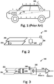
- Figure 1 depicts noise paths caused by automobile engine and electronic components.
- the length of the rod antenna 100 is typically in the range of 10 centimeters to 80 centimeters cm.
- the rod antenna 100 is mounted on the rooftop of a vehicle.
- the received radio signals are amplified by a low noise amplifier positioned at the antenna feeding port.
- the feeding port has two feeding connections, the first connection is at the start of the rod antenna 100 close to the rooftop and the second connection is at the rooftop.
- the engine 104 may be powered by batteries. When DC voltage is converted into variable AC voltage to drive the vehicle's drive train, such conversion also generates electromagnetic fields. These electromagnetic fields induce current and voltage in the vehicle's chassis and rooftop. Since the rooftop is part of the antenna 100, the induced interference is coupled to the antenna feeding port. As depicted, the noise current path 102 passes through the rooftop and chassis and may interfere with the radio reception received through the antenna 100.
- FIG. 2 shows an interference sensor 200.
- the interference sensor 200 includes a first conductive plate 202 and a second conductive plate 204 separated from each other by the distance D. Between the first conductive plate 202 and the second conductive plate 204, there may be a non-conductive material or air.
- the interference sensor 200 also includes a sensor coil 206 that is energized by the electromagnetic field captured by the first conductive plate 202 and the second conductive plate 204 as well as the radio interference captured directly by the coil 206.
- the interference sensor 200 includes two connecting ports 208 to couple the interference sensor 200 with a noise reduction circuit.
- FIG 3 shows an interference sensor 250 in another embodiment.
- the interference sensor 250 includes the first conductive plate 252 and the second conductive plate 254 separated from each other by an arbitrary distance D.
- the first conductive plate 252 and the second conductive plate 254 are coupled to a coil 256 and a resistor 258.
- the coil 256 and the resistor 258 are coupled together in parallel and the resistor 258 is coupled to a capacitor 260.
- the values of the inductor or coil 256, the resistor 258 and the capacitor 260 can be set to address a particular range of frequencies for the purpose of selecting the correlated interference in the received radio broadcast band .
- the two plates 252, 254 along with the coil 256, the resistor 258 and the capacitor 260 form a resonance circuit to select the correlated unwanted noise that is introduced when the plates 252, 254 are coupled to the chassis of the vehicle shown in Figure 1 .
- the capacitance of the sensor plates 252 254 can be approximately 4.5pF
- the inductance of the sensor coil 256 can be approximately 3.8uH
- the value of the tuning capacitor 260 can be approximately 56pF
- the value of the tuning resistor 258 can be 5000ohms.
- the Q factor of the resonance circuit stated above can be approximately 23.5 and the corresponding bandwidth of the resonance circuit can be approximately 450kHz. These values can be tuned to a particular frequency.
- the electric field of the correlated interference induces a voltage between two conductive plates 252, 254.
- the correlated magnetic interference field is measured by a coil 256.
- the interference sensor 250 may also include a current transformer 262 and a signal amplifier 264.
- the vehicle chassis provides the ground for the amplifier circuit 264.
- the current transformer 262 is a step up transformer that includes more number of windings on the secondary side compared to the primary side.
- the interference sensor is resonated at the desired carrier frequency set with a capacitor 260 and the bandwidth of the resonance circuit is set by a resistor 258.
- the current transformer 262 has a primary set of windings for measuring the resonance current that circulates in the resonance circuit that includes the coil 256, the resistor 258 and the capacitor 260.
- the use of the current transformer 262 is advantageous because it provides firstly a high capacitive isolation and secondly a low load impedance that results in a reduction of non-correlated interference signals received by the connection cable.
- the plates 252 and 254 with the sensor coil 256 may be tuned to broadcast frequency by varying the capacitor 260.
- the value of the sensor coil can be in the range of 2 uH to 10 uH.
- the bandwidth of the sensor 250 can be set as using the resistor 258.
- the primary side of the current transformer 262 measures the resonance current generated by the correlated interference fields.
- the secondary side of the current transformer 262 is connected to the amplifier 264 through a cable. The non-correlated interference induced in the cable is reduced due to the low impedance seen from the secondary side of the current transformer 262 and due to the high capacitive isolation of the current transformer.
- the input impedance of the signal amplifier 264 can be 50ohms while the impedance seen from the secondary side of the current transformer 262 is only a few ohms or lower and as such almost shorting the non-correlated interference signals.
- a 40db noise reduction has been measured in a prototype of the noise sensor 250.
- Capacitance of the sensor plates 4.5pF
- Inductance of the sensor coil 3.8uH
- Tuning capacitor 260 56pF
- Resistor 258 5000ohms
- Current transformer 262 Core: toroid 3mm diameter 4C6 material
- Primary 1 winding Secondary 5 windings
- Figure 4 shows an example of the placement of the interference sensors 250 in a vehicle 300.
- the interference sensor 250 is placed where the reception of the broadcast signal is minimal, e.g., inside the vehicle 300 and where the interference is correlated with the interference received by the antenna 100.
- the chassis of the vehicle 300 creates a faraday cage, hence the broadcast signal inside the vehicle 300 is minimal.
- one or more interference sensors 250 may be placed inside the vehicle 300 above driver's seat.
- the interference sensor 250 may be placed inside the vehicle 300 towards the rear, under the antenna 100.
- Under the chassis of the vehicle 300 may also be an advantageous position because the radio signals are attenuated due to the ground which is capacitively coupled to the lower side of the chassis.
- FIG. 5 shows a noise cancellation circuit 400.
- the noise cancellation circuit 400 includes an interference sensor 250.
- the interference sensor 250 may be installed in a vehicle where there is minimal amount of broadcast signal.
- the interference sensor 250 is installed coupled to the chassis of the vehicle 300.
- the interference captured by the interference sensor 250 is amplified by a low noise amplifier 408 and the amplified signal is inputted to a phase and amplitude changer 406 which is controlled by a signal processor 402.
- the phase and amplitude changer 406 is configured to produce a signal that is correlated to the signal from the antenna and similar in amplitude to the signal from the antenna after amplification by the low noise amplifier 406.
- the signal from the antenna includes the broadcast signal as well as the interference signal.
- the signal processor 402 subtracts the signal from the interference sensor path from the signal from the antenna path to produce a relatively noise and interference free broadcast signal.
- the interference sensor 304 is installed close to the chassis of the vehicle 300 and is capacitively coupled to the chassis. Due to the electric field vector orientation, the interference field induces a voltage between the plate 252 and the plate 254.
- the conductive plates are measuring the common model signal which is represented by the electric field on the chassis of the vehicle 300.
- the differential mode signal which are the circulating currents can be measured by means of their magnetic field.
- the magnetic field is captured by the sensor coil 256.
- V 2 x Q 2 ⁇ N Su ⁇ 0 ⁇ r H x F
Landscapes
- Engineering & Computer Science (AREA)
- Computer Networks & Wireless Communication (AREA)
- Signal Processing (AREA)
- Physics & Mathematics (AREA)
- Electromagnetism (AREA)
- General Physics & Mathematics (AREA)
- Quality & Reliability (AREA)
- Life Sciences & Earth Sciences (AREA)
- Sustainable Development (AREA)
- Sustainable Energy (AREA)
- Power Engineering (AREA)
- Transportation (AREA)
- Mechanical Engineering (AREA)
- Noise Elimination (AREA)
Abstract
Description
- An interference in the radio reception occurs when unwanted radio frequency signals disrupt the use of an automobile's radio system. A radio reception can be a broadcast radio reception such as AM, FM, DAB, or reception of mobile phone signals, WIFI, Bluetooth, GNSS and V2X. The radio interference may prevent the radio reception altogether, may cause only a temporary loss of signal, or may affect the quality of the sound. The interference in automobile radios may come from variety of sources. The most common sources for interference are electric and electronic systems in an automobile. One probable cause of this type of interference is the automobile's spark plug wires which degrade over time. Another source of interference can be the charging system of the automobile, especially in electric or hybrid electric automobiles. The alternator that produces electricity to charge the automobile batteries can be a source of electro-magnetic energy that may interfere with the radio reception in an automobile.
- This Summary is provided to introduce a selection of concepts in a simplified form that are further described below in the Detailed Description. This Summary is not intended to identify key features or essential features of the claimed subject matter, nor is it intended to be used to limit the scope of the claimed subject matter.
- In one embodiment, an interference sensor device is disclosed. The interference sensor device includes a first conductive plate and a second conductive plate aligned parallel to the first conductive plate. A non-conductive matter is included between the first conductive plate and the second conductive plate. A band pass filter is formed with the first conductive plate and the second conductive plate. The band pass filter includes a sensor coil. A current transformer having a primary side and a secondary side is included. The primary side is coupled with the band pass filter, and the secondary side is configured to be coupled with a cable. The current transformer provides a high capacitive isolation. In some examples, the band pass filter includes a resistor that is coupled with the sensor coil in parallel. The band pass filter may also include a tuning capacitor that is coupled with the primary side of the current transformer.
- In another embodiment, a vehicle is disclosed. The vehicle includes the interference sensor device installed at the inside bottom of the chassis of the vehicle. In another example, the interference sensor device may be installed at the outside bottom of the chassis of the vehicle. In yet another example, the interference sensor device may be installed at inside top of chassis of the vehicle, above driver seat or at inside top of the chassis of the vehicle under the antenna.
- In an example, a broadcast noise filtering system is disclosed. The broadcast noise filtering system includes the interference sensor device, a signal processor configured to receive a first signal from an antenna and a second signal from the interference sensor device and a phase/amplitude changer coupled to the signal processor and the interference sensor device configured to be controlled by the signal processor through a feedback loop to correct phase of the second signal. The signal processor is configured to subtract the second signal from the first signal. In one or more embodiments, the interference sensor device may include: a first conductive plate; a second conductive plate aligned parallel to the first conductive plate; a non-conductive matter between the first conductive plate and the second conductive plate; a low pass filter coupled with the first conductive plate and the second conductive plate, wherein the low pass filter includes a sensor coil; and a current transformer having a primary side and a secondary side, wherein the primary side is coupled with the low pass filter, and the secondary side is configured to be coupled with a cable, wherein the current transformer is a step up transformer.
- The broadcast filtering system may further include an antenna signal amplifier coupled between an antenna port and the signal processor and an interference signal amplifier coupled between the interference sensor device and the phase/amplitude changer.
- So that the way the above recited features of the present invention can be understood in detail, a more particular description of the invention, briefly summarized above, may be had by reference to embodiments, some of which are illustrated in the appended drawings. It is to be noted, however, that the appended drawings illustrate only typical embodiments of this invention and are therefore not to be considered limiting of its scope, for the invention may admit to other equally effective embodiments. Advantages of the subject matter claimed will become apparent to those skilled in the art upon reading this description in conjunction with the accompanying drawings, in which like reference numerals have been used to designate like elements, and in which:
-
FIG. 1 depicts noise paths caused by automobile engine and electronic components; -
FIG. 2 shows a noise sensor in accordance with one or more embodiments of the present disclosure; -
FIG. 3 shows a noise sensor in accordance with one or more embodiments of the present disclosure; -
FIG. 4 shows a plurality of noise sensors installed in an automobile in accordance with one or more embodiments of the present disclosure; and -
FIG. 5 shows a noise cancellation circuit in accordance with one or more embodiments of the present disclosure. - Note that figures are not drawn to scale. Intermediate steps between figure transitions have been omitted so as not to obfuscate the disclosure. Those intermediate steps are known to a person skilled in the art.
- Many well-known manufacturing steps, components, and connectors have been omitted or not described in detail in the description so as not to obfuscate the present disclosure.
- A version of a vehicle interference sensor is described in
US Patent Number 10,381,995 - A vehicle interference sensor having two conductive plates and a filter is described herein. The conductive plates includes a substrate between the plates that together with the plates form a capacitor. The coil is configured to sense or receive magnetic fields in one or more directions. A coupling unit is provided to couple the capacitive plates with the coil. An additional capacitor and a resistor may be employed to tune the interference sensor to the resonance frequency of the broadcast signal.
-
Figure 1 depicts noise paths caused by automobile engine and electronic components. The length of therod antenna 100 is typically in the range of 10 centimeters to 80 centimeters cm. Therod antenna 100 is mounted on the rooftop of a vehicle. The received radio signals are amplified by a low noise amplifier positioned at the antenna feeding port. The feeding port has two feeding connections, the first connection is at the start of therod antenna 100 close to the rooftop and the second connection is at the rooftop. - The
engine 104 may be powered by batteries. When DC voltage is converted into variable AC voltage to drive the vehicle's drive train, such conversion also generates electromagnetic fields. These electromagnetic fields induce current and voltage in the vehicle's chassis and rooftop. Since the rooftop is part of theantenna 100, the induced interference is coupled to the antenna feeding port. As depicted, the noisecurrent path 102 passes through the rooftop and chassis and may interfere with the radio reception received through theantenna 100. -
Figure 2 shows aninterference sensor 200. Theinterference sensor 200 includes a firstconductive plate 202 and a secondconductive plate 204 separated from each other by the distance D. Between the firstconductive plate 202 and the secondconductive plate 204, there may be a non-conductive material or air. Theinterference sensor 200 also includes asensor coil 206 that is energized by the electromagnetic field captured by the firstconductive plate 202 and the secondconductive plate 204 as well as the radio interference captured directly by thecoil 206. Theinterference sensor 200 includes two connectingports 208 to couple theinterference sensor 200 with a noise reduction circuit. -
Figure 3 shows aninterference sensor 250 in another embodiment. Theinterference sensor 250 includes the firstconductive plate 252 and the secondconductive plate 254 separated from each other by an arbitrary distance D. The firstconductive plate 252 and the secondconductive plate 254 are coupled to acoil 256 and aresistor 258. Thecoil 256 and theresistor 258 are coupled together in parallel and theresistor 258 is coupled to acapacitor 260. The values of the inductor orcoil 256, theresistor 258 and thecapacitor 260 can be set to address a particular range of frequencies for the purpose of selecting the correlated interference in the received radio broadcast band . - The two
plates coil 256, theresistor 258 and thecapacitor 260 form a resonance circuit to select the correlated unwanted noise that is introduced when theplates Figure 1 . In one test example, the capacitance of thesensor plates 252 254 can be approximately 4.5pF, the inductance of thesensor coil 256 can be approximately 3.8uH, the value of thetuning capacitor 260 can be approximately 56pF and the value of thetuning resistor 258 can be 5000ohms. The Q factor of the resonance circuit stated above can be approximately 23.5 and the corresponding bandwidth of the resonance circuit can be approximately 450kHz. These values can be tuned to a particular frequency. - The electric field of the correlated interference induces a voltage between two
conductive plates coil 256. Theinterference sensor 250 may also include acurrent transformer 262 and asignal amplifier 264. The vehicle chassis provides the ground for theamplifier circuit 264. In one example, thecurrent transformer 262 is a step up transformer that includes more number of windings on the secondary side compared to the primary side. - The interference sensor is resonated at the desired carrier frequency set with a
capacitor 260 and the bandwidth of the resonance circuit is set by aresistor 258. Thecurrent transformer 262 has a primary set of windings for measuring the resonance current that circulates in the resonance circuit that includes thecoil 256, theresistor 258 and thecapacitor 260. The use of thecurrent transformer 262 is advantageous because it provides firstly a high capacitive isolation and secondly a low load impedance that results in a reduction of non-correlated interference signals received by the connection cable. - The
plates sensor coil 256 may be tuned to broadcast frequency by varying thecapacitor 260. In some examples, the value of the sensor coil can be in the range of 2 uH to 10 uH. The bandwidth of thesensor 250 can be set as using theresistor 258. The primary side of thecurrent transformer 262 measures the resonance current generated by the correlated interference fields. The secondary side of thecurrent transformer 262 is connected to theamplifier 264 through a cable. The non-correlated interference induced in the cable is reduced due to the low impedance seen from the secondary side of thecurrent transformer 262 and due to the high capacitive isolation of the current transformer. In one example, the input impedance of thesignal amplifier 264 can be 50ohms while the impedance seen from the secondary side of thecurrent transformer 262 is only a few ohms or lower and as such almost shorting the non-correlated interference signals. In one example, a 40db noise reduction has been measured in a prototype of thenoise sensor 250. - The values used in the prototype: Capacitance of the sensor plates = 4.5pF, Inductance of the sensor coil=3.8uH,
Tuning capacitor 260 = 56pF,Resistor 258 = 5000ohms, Current transformer 262:Core: toroid 3mm diameter 4C6 material Primary : 1 winding Secondary 5 windings -
Figure 4 shows an example of the placement of theinterference sensors 250 in avehicle 300. Theinterference sensor 250 is placed where the reception of the broadcast signal is minimal, e.g., inside thevehicle 300 and where the interference is correlated with the interference received by theantenna 100. The chassis of thevehicle 300 creates a faraday cage, hence the broadcast signal inside thevehicle 300 is minimal. As depicted, one ormore interference sensors 250 may be placed inside thevehicle 300 above driver's seat. Alternatively, theinterference sensor 250 may be placed inside thevehicle 300 towards the rear, under theantenna 100. Under the chassis of thevehicle 300 may also be an advantageous position because the radio signals are attenuated due to the ground which is capacitively coupled to the lower side of the chassis. -
Figure 5 shows anoise cancellation circuit 400. Thenoise cancellation circuit 400 includes aninterference sensor 250. As discussed inFigure 4 , theinterference sensor 250 may be installed in a vehicle where there is minimal amount of broadcast signal. Theinterference sensor 250 is installed coupled to the chassis of thevehicle 300. The interference captured by theinterference sensor 250 is amplified by alow noise amplifier 408 and the amplified signal is inputted to a phase andamplitude changer 406 which is controlled by asignal processor 402. The phase andamplitude changer 406 is configured to produce a signal that is correlated to the signal from the antenna and similar in amplitude to the signal from the antenna after amplification by thelow noise amplifier 406. The signal from the antenna includes the broadcast signal as well as the interference signal. Thesignal processor 402 subtracts the signal from the interference sensor path from the signal from the antenna path to produce a relatively noise and interference free broadcast signal. - Going back to
Figure 4 , theinterference sensor 304 is installed close to the chassis of thevehicle 300 and is capacitively coupled to the chassis. Due to the electric field vector orientation, the interference field induces a voltage between theplate 252 and theplate 254. The field to voltage transfer function may be defined as follows:
- Where:
- V1 = induced voltage
- E = electric interference field
- D = distance between the plates
- Cs = capacity formed by the two plates
- Camp = capacity of the amplifier connected to the sensor
- εr = dielectric constant of the substrate between the two plates
- Q = quality factor of the sensor including amplifier
- x = position on the chassis
- The conductive plates are measuring the common model signal which is represented by the electric field on the chassis of the
vehicle 300. The differential mode signal, which are the circulating currents can be measured by means of their magnetic field. The magnetic field is captured by thesensor coil 256. - The conversion from magnetic interference fields to voltage in one coil can be defined as follows:

- Where:
- N = the number of turns in the coil
- F = frequency
- Su = surface area of the coil core
- H = the magnetic field at the receive coil
- µο = 4 · pi · 10-7 H/m is magnetic permeability of vacuum
- µr = relative magnetic permeability of the receive coil rod
- x = position at the chassis
- Q = quality factor of the sensor resonance circuit
- Some or all of these embodiments may be combined, some may be omitted altogether, and additional process steps can be added while still achieving the products described herein. Thus, the subject matter described herein can be embodied in many different variations, and all such variations are contemplated to be within the scope of what is claimed.
- While one or more implementations have been described by way of example and in terms of the specific embodiments, it is to be understood that one or more implementations are not limited to the disclosed embodiments. To the contrary, it is intended to cover various modifications and similar arrangements as would be apparent to those skilled in the art. Therefore, the scope of the appended claims should be accorded the broadest interpretation so as to encompass all such modifications and similar arrangements.
- The use of the terms "a" and "an" and "the" and similar referents in the context of describing the subject matter (particularly in the context of the following claims) are to be construed to cover both the singular and the plural, unless otherwise indicated herein or clearly contradicted by context. Recitation of ranges of values herein are merely intended to serve as a shorthand method of referring individually to each separate value falling within the range, unless otherwise indicated herein, and each separate value is incorporated into the specification as if it were individually recited herein. Furthermore, the foregoing description is for the purpose of illustration only, and not for the purpose of limitation, as the scope of protection sought is defined by the claims as set forth hereinafter together with any equivalents thereof entitled to. The use of any and all examples, or exemplary language (e.g., "such as") provided herein, is intended merely to better illustrate the subject matter and does not pose a limitation on the scope of the subject matter unless otherwise claimed. The use of the term "based on" and other like phrases indicating a condition for bringing about a result, both in the claims and in the written description, is not intended to foreclose any other conditions that bring about that result. No language in the specification should be construed as indicating any non-claimed element as essential to the practice of the invention as claimed.
- Preferred embodiments are described herein, including the best mode known to the inventor for carrying out the claimed subject matter. Of course, variations of those preferred embodiments will become apparent to those of ordinary skill in the art upon reading the foregoing description. The inventor expects skilled artisans to employ such variations as appropriate, and the inventor intends for the claimed subject matter to be practiced otherwise than as specifically described herein. Accordingly, this claimed subject matter includes all modifications and equivalents of the subject matter recited in the claims appended hereto as permitted by applicable law. Moreover, any combination of the above-described elements in all possible variations thereof is encompassed unless otherwise indicated herein or otherwise clearly contradicted by context.
Claims (10)
- An interference sensor device, comprising:a first conductive plate;a second conductive plate aligned parallel to the first conductive plate;a non-conductive matter between the first conductive plate and the second conductive plate;a band pass filter formed with the first conductive plate and the second conductive plate, wherein the band pass filter includes a sensor coil;a current transformer having a primary side and a secondary side, wherein the primary side is coupled with the low pass filter, and the secondary side is configured to be coupled with a cable, wherein the current transformer having a high capacitive isolation.
- The interference sensor device of claim 1, wherein the band pass filter includes a resistor that is coupled with the sensor coil in parallel.
- The interference sensor device of claim 1 or 2, wherein the band pass filter includes a tuning capacitor that is coupled with the primary side of the current transformer.
- A vehicle, comprising the interference sensor device of any of claims 1 to 3, installed at inside bottom of chassis of the vehicle.
- A vehicle, comprising the interference sensor device of any of claims 1 to 3, installed at outside bottom of chassis of the vehicle.
- A vehicle, comprising the interference sensor device of any of claims 1 to 3, installed at inside top of chassis of the vehicle, above driver seat.
- A broadcast noise filtering system, comprising:an interference sensor device according to any of claims 1 to 3;a signal processor configured to receive a first signal from an antenna and a second signal from the interference sensor device; anda phase/amplitude changer coupled to the signal processor and the interference sensor device configured to be controlled by the signal processor through a feedback loop to correct phase and amplitude of the second signal;wherein the signal processor is configured to subtract the second signal from the first signal.
- The broadcast noise filtering system of claim 7, further including an antenna signal amplifier coupled between an antenna port and the signal processor.
- The broadcast noise filtering system of claim 7 or 8, further including an interference signal amplifier coupled between the interference sensor device and the phase/amplitude changer.
- The broadcast noise filtering system of any of claims 7 to 9, wherein a value of the sensor coil is 2 uH to 10 uH.
Applications Claiming Priority (1)
| Application Number | Priority Date | Filing Date | Title |
|---|---|---|---|
| US16/775,203 US11038605B1 (en) | 2020-01-28 | 2020-01-28 | Vehicle radio interference sensor |
Publications (2)
| Publication Number | Publication Date |
|---|---|
| EP3860004A1 true EP3860004A1 (en) | 2021-08-04 |
| EP3860004B1 EP3860004B1 (en) | 2024-03-20 |
Family
ID=74125068
Family Applications (1)
| Application Number | Title | Priority Date | Filing Date |
|---|---|---|---|
| EP21150675.3A Active EP3860004B1 (en) | 2020-01-28 | 2021-01-08 | Vehicle radio interference sensor |
Country Status (3)
| Country | Link |
|---|---|
| US (1) | US11038605B1 (en) |
| EP (1) | EP3860004B1 (en) |
| CN (1) | CN113252993B (en) |
Families Citing this family (1)
| Publication number | Priority date | Publication date | Assignee | Title |
|---|---|---|---|---|
| DE102018209001A1 (en) * | 2018-06-07 | 2019-12-12 | Robert Bosch Gmbh | Control device device for a motor vehicle, motor vehicle |
Citations (5)
| Publication number | Priority date | Publication date | Assignee | Title |
|---|---|---|---|---|
| EP0777339A1 (en) * | 1995-11-30 | 1997-06-04 | STMicroelectronics S.A. | Signal transmission circuit |
| US20010019264A1 (en) * | 1994-07-22 | 2001-09-06 | Shattil Steven J. | Method and apparatus for a full-duplex electromagnetic transceiver |
| US20020039028A1 (en) * | 1999-11-05 | 2002-04-04 | Philip Douglas | Noncontact signal analyzer |
| JP2011176659A (en) * | 2010-02-25 | 2011-09-08 | Panasonic Corp | Noise sensor phase amplitude adjusting circuit and radio equipment employing the same |
| US10381995B1 (en) | 2018-07-19 | 2019-08-13 | Nxp B.V. | Vehicle radio interference sensor device |
Family Cites Families (26)
| Publication number | Priority date | Publication date | Assignee | Title |
|---|---|---|---|---|
| US3816669A (en) * | 1972-11-01 | 1974-06-11 | Electrospace Corp | Apparatus for detecting telephone ringing signals |
| JPS55148376A (en) * | 1979-05-09 | 1980-11-18 | Matsushita Electric Industrial Co Ltd | Noise preventive connector |
| US4731578A (en) * | 1985-05-02 | 1988-03-15 | Aeroquip Corporation | Electrical sensing system for measuring ferrous particles within a fluid |
| FR2610153B1 (en) * | 1987-01-28 | 1989-04-07 | Merlin Gerin | DISSIPATIVE LOW PASS FILTER |
| US4875019A (en) * | 1988-07-21 | 1989-10-17 | Bahr Technologies, Inc. | Receiver preamplifier with tuned circuit adapted for Loran reception |
| US5103197A (en) * | 1989-06-09 | 1992-04-07 | Lk-Products Oy | Ceramic band-pass filter |
| ES2070702B1 (en) * | 1992-12-31 | 1997-03-01 | Alcatel Standard Electrica | MAGNETIC FIELD SENSOR DEVICE. |
| US5600248A (en) * | 1995-06-21 | 1997-02-04 | Dipl.-Ing H. Horstmann Gmbh | Fault distance locator for underground cable circuits |
| US5684466A (en) * | 1995-09-12 | 1997-11-04 | The Charles Machine Work, Inc. | Electrical strike system control for subsurface boring equipment |
| DE19847653A1 (en) | 1998-10-15 | 2000-04-20 | Heinz Lindenmeier | Device for suppressing the reception of interference emitted by the vehicle |
| JP2001060809A (en) * | 1999-08-19 | 2001-03-06 | Sony Corp | Circuit elements and printed wiring boards |
| GB2389973B (en) * | 2002-06-18 | 2006-02-15 | Alstom | Improvements relating to electrical filters |
| US6831469B2 (en) * | 2003-03-10 | 2004-12-14 | Honeywell International Inc. | Micropower apparatus for low impedance measurements |
| JP2009027636A (en) * | 2007-07-23 | 2009-02-05 | Tokai Rika Co Ltd | Radio signal receiving apparatus |
| CN101504432A (en) * | 2009-01-24 | 2009-08-12 | 国网电力科学研究院 | Transient electromagnetic field measuring method for transforming plant |
| GB2484304B (en) * | 2010-10-06 | 2012-10-10 | Robert Horsfall | Turning off a projector |
| JP5599301B2 (en) | 2010-12-27 | 2014-10-01 | 三菱電機株式会社 | In-vehicle power line communication system |
| US9070968B2 (en) * | 2012-04-02 | 2015-06-30 | Apple Inc. | Methods for characterizing tunable radio-frequency elements in wireless electronic devices |
| JP5851364B2 (en) | 2012-08-14 | 2016-02-03 | 本田技研工業株式会社 | Electromagnetic interference measurement device and electromagnetic interference evaluation system |
| US9444311B2 (en) * | 2012-08-28 | 2016-09-13 | Mitsubishi Electric Corporation | Electric driving device and method for manufacturing electric driving device |
| WO2015153503A2 (en) * | 2014-03-31 | 2015-10-08 | Hubbell Incorporated | Systems and methods for detecting and identifying arcing based on numerical analysis |
| JP6028000B2 (en) * | 2014-05-07 | 2016-11-16 | 株式会社エクォス・リサーチ | Power transmission system |
| EP3130897B1 (en) * | 2015-08-10 | 2022-10-19 | Harman Becker Automotive Systems GmbH | Noise and vibration sensing |
| DE102016200536B3 (en) * | 2015-12-16 | 2017-02-23 | Bayerische Motoren Werke Aktiengesellschaft | Vehicle with a twin-flow exhaust system |
| MX2020000895A (en) * | 2017-07-26 | 2020-07-22 | Panoramic Power Ltd | Timing synchronization of self-powered power sensors and a central controller collecting samples therefrom. |
| US10770978B2 (en) * | 2018-03-23 | 2020-09-08 | Utah State University | DC power supply from a constant current source |
-
2020
- 2020-01-28 US US16/775,203 patent/US11038605B1/en active Active
-
2021
- 2021-01-08 EP EP21150675.3A patent/EP3860004B1/en active Active
- 2021-01-11 CN CN202110032639.8A patent/CN113252993B/en active Active
Patent Citations (5)
| Publication number | Priority date | Publication date | Assignee | Title |
|---|---|---|---|---|
| US20010019264A1 (en) * | 1994-07-22 | 2001-09-06 | Shattil Steven J. | Method and apparatus for a full-duplex electromagnetic transceiver |
| EP0777339A1 (en) * | 1995-11-30 | 1997-06-04 | STMicroelectronics S.A. | Signal transmission circuit |
| US20020039028A1 (en) * | 1999-11-05 | 2002-04-04 | Philip Douglas | Noncontact signal analyzer |
| JP2011176659A (en) * | 2010-02-25 | 2011-09-08 | Panasonic Corp | Noise sensor phase amplitude adjusting circuit and radio equipment employing the same |
| US10381995B1 (en) | 2018-07-19 | 2019-08-13 | Nxp B.V. | Vehicle radio interference sensor device |
Also Published As
| Publication number | Publication date |
|---|---|
| CN113252993B (en) | 2026-01-27 |
| EP3860004B1 (en) | 2024-03-20 |
| US11038605B1 (en) | 2021-06-15 |
| CN113252993A (en) | 2021-08-13 |
Similar Documents
| Publication | Publication Date | Title |
|---|---|---|
| US6130645A (en) | Combination wide band antenna and heating element on a window of a vehicle | |
| US11323155B2 (en) | Decoupler for near field communications interface module on vehicle conductive surface | |
| US4791426A (en) | Active antenna in the rear window of a motor vehicle | |
| US9018904B2 (en) | Wireless battery charging apparatus mounted in a vehicle designed to reduce electromagnetic interference | |
| KR20210046727A (en) | A device for detecting items of electronic equipment and communicating with two near field communication antennas | |
| EP0346089B1 (en) | Reception system | |
| EP0963002A1 (en) | Glass window antenna system for motor vehicles | |
| US6184837B1 (en) | Windowpane antenna combined with a resisting heating area | |
| EP3860004B1 (en) | Vehicle radio interference sensor | |
| CN110736882B (en) | Vehicle radio interference sensor device | |
| US4717921A (en) | Automobile antenna system | |
| US10763921B1 (en) | Near-field electromagnetic induction device | |
| US5198825A (en) | Reception system for a motor vehicle | |
| US4816837A (en) | Automobile antenna system | |
| KR910001385B1 (en) | Signal discriminator and signal discrimination method | |
| EP3157101B1 (en) | Electromagnetic device | |
| US11017941B2 (en) | Isolation transformer with low unwanted resonances, energy transfer device having an isolation transformer and energy transfer device for wireless transfer of energy having an isolation transformer | |
| JP3508217B2 (en) | Automotive glass antenna device | |
| JPH04287405A (en) | Glass antenna for automobile | |
| US10384551B2 (en) | Electromagnetic decoupling of an antenna unit of a motor vehicle from an energy coupling device | |
| EP0213743B1 (en) | Automobile antenna system | |
| US12176605B2 (en) | Transmission device for a motor vehicle for transmitting a radio signal, wireless key system, and motor vehicle | |
| JP3069067B2 (en) | Automotive glass antenna device | |
| JPH11127013A (en) | Terminal device for automotive glass antenna | |
| CN120934210A (en) | Coil assembly, foreign matter detection system, wireless charging system and vehicle |
Legal Events
| Date | Code | Title | Description |
|---|---|---|---|
| PUAI | Public reference made under article 153(3) epc to a published international application that has entered the european phase |
Free format text: ORIGINAL CODE: 0009012 |
|
| STAA | Information on the status of an ep patent application or granted ep patent |
Free format text: STATUS: THE APPLICATION HAS BEEN PUBLISHED |
|
| AK | Designated contracting states |
Kind code of ref document: A1 Designated state(s): AL AT BE BG CH CY CZ DE DK EE ES FI FR GB GR HR HU IE IS IT LI LT LU LV MC MK MT NL NO PL PT RO RS SE SI SK SM TR |
|
| STAA | Information on the status of an ep patent application or granted ep patent |
Free format text: STATUS: REQUEST FOR EXAMINATION WAS MADE |
|
| 17P | Request for examination filed |
Effective date: 20220204 |
|
| RBV | Designated contracting states (corrected) |
Designated state(s): AL AT BE BG CH CY CZ DE DK EE ES FI FR GB GR HR HU IE IS IT LI LT LU LV MC MK MT NL NO PL PT RO RS SE SI SK SM TR |
|
| GRAP | Despatch of communication of intention to grant a patent |
Free format text: ORIGINAL CODE: EPIDOSNIGR1 |
|
| STAA | Information on the status of an ep patent application or granted ep patent |
Free format text: STATUS: GRANT OF PATENT IS INTENDED |
|
| INTG | Intention to grant announced |
Effective date: 20231214 |
|
| GRAS | Grant fee paid |
Free format text: ORIGINAL CODE: EPIDOSNIGR3 |
|
| GRAA | (expected) grant |
Free format text: ORIGINAL CODE: 0009210 |
|
| STAA | Information on the status of an ep patent application or granted ep patent |
Free format text: STATUS: THE PATENT HAS BEEN GRANTED |
|
| AK | Designated contracting states |
Kind code of ref document: B1 Designated state(s): AL AT BE BG CH CY CZ DE DK EE ES FI FR GB GR HR HU IE IS IT LI LT LU LV MC MK MT NL NO PL PT RO RS SE SI SK SM TR |
|
| REG | Reference to a national code |
Ref country code: GB Ref legal event code: FG4D |
|
| REG | Reference to a national code |
Ref country code: CH Ref legal event code: EP |
|
| REG | Reference to a national code |
Ref country code: DE Ref legal event code: R096 Ref document number: 602021010523 Country of ref document: DE |
|
| REG | Reference to a national code |
Ref country code: IE Ref legal event code: FG4D |
|
| PG25 | Lapsed in a contracting state [announced via postgrant information from national office to epo] |
Ref country code: LT Free format text: LAPSE BECAUSE OF FAILURE TO SUBMIT A TRANSLATION OF THE DESCRIPTION OR TO PAY THE FEE WITHIN THE PRESCRIBED TIME-LIMIT Effective date: 20240320 |
|
| REG | Reference to a national code |
Ref country code: LT Ref legal event code: MG9D |
|
| PG25 | Lapsed in a contracting state [announced via postgrant information from national office to epo] |
Ref country code: GR Free format text: LAPSE BECAUSE OF FAILURE TO SUBMIT A TRANSLATION OF THE DESCRIPTION OR TO PAY THE FEE WITHIN THE PRESCRIBED TIME-LIMIT Effective date: 20240621 |
|
| PG25 | Lapsed in a contracting state [announced via postgrant information from national office to epo] |
Ref country code: HR Free format text: LAPSE BECAUSE OF FAILURE TO SUBMIT A TRANSLATION OF THE DESCRIPTION OR TO PAY THE FEE WITHIN THE PRESCRIBED TIME-LIMIT Effective date: 20240320 Ref country code: RS Free format text: LAPSE BECAUSE OF FAILURE TO SUBMIT A TRANSLATION OF THE DESCRIPTION OR TO PAY THE FEE WITHIN THE PRESCRIBED TIME-LIMIT Effective date: 20240620 |
|
| REG | Reference to a national code |
Ref country code: NL Ref legal event code: MP Effective date: 20240320 |
|
| PG25 | Lapsed in a contracting state [announced via postgrant information from national office to epo] |
Ref country code: RS Free format text: LAPSE BECAUSE OF FAILURE TO SUBMIT A TRANSLATION OF THE DESCRIPTION OR TO PAY THE FEE WITHIN THE PRESCRIBED TIME-LIMIT Effective date: 20240620 Ref country code: NO Free format text: LAPSE BECAUSE OF FAILURE TO SUBMIT A TRANSLATION OF THE DESCRIPTION OR TO PAY THE FEE WITHIN THE PRESCRIBED TIME-LIMIT Effective date: 20240620 Ref country code: LT Free format text: LAPSE BECAUSE OF FAILURE TO SUBMIT A TRANSLATION OF THE DESCRIPTION OR TO PAY THE FEE WITHIN THE PRESCRIBED TIME-LIMIT Effective date: 20240320 Ref country code: HR Free format text: LAPSE BECAUSE OF FAILURE TO SUBMIT A TRANSLATION OF THE DESCRIPTION OR TO PAY THE FEE WITHIN THE PRESCRIBED TIME-LIMIT Effective date: 20240320 Ref country code: GR Free format text: LAPSE BECAUSE OF FAILURE TO SUBMIT A TRANSLATION OF THE DESCRIPTION OR TO PAY THE FEE WITHIN THE PRESCRIBED TIME-LIMIT Effective date: 20240621 Ref country code: FI Free format text: LAPSE BECAUSE OF FAILURE TO SUBMIT A TRANSLATION OF THE DESCRIPTION OR TO PAY THE FEE WITHIN THE PRESCRIBED TIME-LIMIT Effective date: 20240320 Ref country code: BG Free format text: LAPSE BECAUSE OF FAILURE TO SUBMIT A TRANSLATION OF THE DESCRIPTION OR TO PAY THE FEE WITHIN THE PRESCRIBED TIME-LIMIT Effective date: 20240320 |
|
| REG | Reference to a national code |
Ref country code: AT Ref legal event code: MK05 Ref document number: 1668757 Country of ref document: AT Kind code of ref document: T Effective date: 20240320 |
|
| PG25 | Lapsed in a contracting state [announced via postgrant information from national office to epo] |
Ref country code: SE Free format text: LAPSE BECAUSE OF FAILURE TO SUBMIT A TRANSLATION OF THE DESCRIPTION OR TO PAY THE FEE WITHIN THE PRESCRIBED TIME-LIMIT Effective date: 20240320 Ref country code: LV Free format text: LAPSE BECAUSE OF FAILURE TO SUBMIT A TRANSLATION OF THE DESCRIPTION OR TO PAY THE FEE WITHIN THE PRESCRIBED TIME-LIMIT Effective date: 20240320 |
|
| PG25 | Lapsed in a contracting state [announced via postgrant information from national office to epo] |
Ref country code: NL Free format text: LAPSE BECAUSE OF FAILURE TO SUBMIT A TRANSLATION OF THE DESCRIPTION OR TO PAY THE FEE WITHIN THE PRESCRIBED TIME-LIMIT Effective date: 20240320 |
|
| PG25 | Lapsed in a contracting state [announced via postgrant information from national office to epo] |
Ref country code: NL Free format text: LAPSE BECAUSE OF FAILURE TO SUBMIT A TRANSLATION OF THE DESCRIPTION OR TO PAY THE FEE WITHIN THE PRESCRIBED TIME-LIMIT Effective date: 20240320 |
|
| PG25 | Lapsed in a contracting state [announced via postgrant information from national office to epo] |
Ref country code: IS Free format text: LAPSE BECAUSE OF FAILURE TO SUBMIT A TRANSLATION OF THE DESCRIPTION OR TO PAY THE FEE WITHIN THE PRESCRIBED TIME-LIMIT Effective date: 20240720 |
|
| PG25 | Lapsed in a contracting state [announced via postgrant information from national office to epo] |
Ref country code: PT Free format text: LAPSE BECAUSE OF FAILURE TO SUBMIT A TRANSLATION OF THE DESCRIPTION OR TO PAY THE FEE WITHIN THE PRESCRIBED TIME-LIMIT Effective date: 20240722 Ref country code: SM Free format text: LAPSE BECAUSE OF FAILURE TO SUBMIT A TRANSLATION OF THE DESCRIPTION OR TO PAY THE FEE WITHIN THE PRESCRIBED TIME-LIMIT Effective date: 20240320 |
|
| PG25 | Lapsed in a contracting state [announced via postgrant information from national office to epo] |
Ref country code: ES Free format text: LAPSE BECAUSE OF FAILURE TO SUBMIT A TRANSLATION OF THE DESCRIPTION OR TO PAY THE FEE WITHIN THE PRESCRIBED TIME-LIMIT Effective date: 20240320 |
|
| PG25 | Lapsed in a contracting state [announced via postgrant information from national office to epo] |
Ref country code: CZ Free format text: LAPSE BECAUSE OF FAILURE TO SUBMIT A TRANSLATION OF THE DESCRIPTION OR TO PAY THE FEE WITHIN THE PRESCRIBED TIME-LIMIT Effective date: 20240320 Ref country code: EE Free format text: LAPSE BECAUSE OF FAILURE TO SUBMIT A TRANSLATION OF THE DESCRIPTION OR TO PAY THE FEE WITHIN THE PRESCRIBED TIME-LIMIT Effective date: 20240320 |
|
| PG25 | Lapsed in a contracting state [announced via postgrant information from national office to epo] |
Ref country code: AT Free format text: LAPSE BECAUSE OF FAILURE TO SUBMIT A TRANSLATION OF THE DESCRIPTION OR TO PAY THE FEE WITHIN THE PRESCRIBED TIME-LIMIT Effective date: 20240320 |
|
| PG25 | Lapsed in a contracting state [announced via postgrant information from national office to epo] |
Ref country code: PL Free format text: LAPSE BECAUSE OF FAILURE TO SUBMIT A TRANSLATION OF THE DESCRIPTION OR TO PAY THE FEE WITHIN THE PRESCRIBED TIME-LIMIT Effective date: 20240320 |
|
| PG25 | Lapsed in a contracting state [announced via postgrant information from national office to epo] |
Ref country code: SK Free format text: LAPSE BECAUSE OF FAILURE TO SUBMIT A TRANSLATION OF THE DESCRIPTION OR TO PAY THE FEE WITHIN THE PRESCRIBED TIME-LIMIT Effective date: 20240320 |
|
| PG25 | Lapsed in a contracting state [announced via postgrant information from national office to epo] |
Ref country code: SM Free format text: LAPSE BECAUSE OF FAILURE TO SUBMIT A TRANSLATION OF THE DESCRIPTION OR TO PAY THE FEE WITHIN THE PRESCRIBED TIME-LIMIT Effective date: 20240320 Ref country code: SK Free format text: LAPSE BECAUSE OF FAILURE TO SUBMIT A TRANSLATION OF THE DESCRIPTION OR TO PAY THE FEE WITHIN THE PRESCRIBED TIME-LIMIT Effective date: 20240320 Ref country code: RO Free format text: LAPSE BECAUSE OF FAILURE TO SUBMIT A TRANSLATION OF THE DESCRIPTION OR TO PAY THE FEE WITHIN THE PRESCRIBED TIME-LIMIT Effective date: 20240320 Ref country code: PT Free format text: LAPSE BECAUSE OF FAILURE TO SUBMIT A TRANSLATION OF THE DESCRIPTION OR TO PAY THE FEE WITHIN THE PRESCRIBED TIME-LIMIT Effective date: 20240722 Ref country code: PL Free format text: LAPSE BECAUSE OF FAILURE TO SUBMIT A TRANSLATION OF THE DESCRIPTION OR TO PAY THE FEE WITHIN THE PRESCRIBED TIME-LIMIT Effective date: 20240320 Ref country code: IS Free format text: LAPSE BECAUSE OF FAILURE TO SUBMIT A TRANSLATION OF THE DESCRIPTION OR TO PAY THE FEE WITHIN THE PRESCRIBED TIME-LIMIT Effective date: 20240720 Ref country code: ES Free format text: LAPSE BECAUSE OF FAILURE TO SUBMIT A TRANSLATION OF THE DESCRIPTION OR TO PAY THE FEE WITHIN THE PRESCRIBED TIME-LIMIT Effective date: 20240320 Ref country code: EE Free format text: LAPSE BECAUSE OF FAILURE TO SUBMIT A TRANSLATION OF THE DESCRIPTION OR TO PAY THE FEE WITHIN THE PRESCRIBED TIME-LIMIT Effective date: 20240320 Ref country code: CZ Free format text: LAPSE BECAUSE OF FAILURE TO SUBMIT A TRANSLATION OF THE DESCRIPTION OR TO PAY THE FEE WITHIN THE PRESCRIBED TIME-LIMIT Effective date: 20240320 Ref country code: AT Free format text: LAPSE BECAUSE OF FAILURE TO SUBMIT A TRANSLATION OF THE DESCRIPTION OR TO PAY THE FEE WITHIN THE PRESCRIBED TIME-LIMIT Effective date: 20240320 |
|
| PG25 | Lapsed in a contracting state [announced via postgrant information from national office to epo] |
Ref country code: IT Free format text: LAPSE BECAUSE OF FAILURE TO SUBMIT A TRANSLATION OF THE DESCRIPTION OR TO PAY THE FEE WITHIN THE PRESCRIBED TIME-LIMIT Effective date: 20240320 |
|
| REG | Reference to a national code |
Ref country code: DE Ref legal event code: R097 Ref document number: 602021010523 Country of ref document: DE |
|
| PG25 | Lapsed in a contracting state [announced via postgrant information from national office to epo] |
Ref country code: IT Free format text: LAPSE BECAUSE OF FAILURE TO SUBMIT A TRANSLATION OF THE DESCRIPTION OR TO PAY THE FEE WITHIN THE PRESCRIBED TIME-LIMIT Effective date: 20240320 |
|
| PG25 | Lapsed in a contracting state [announced via postgrant information from national office to epo] |
Ref country code: DK Free format text: LAPSE BECAUSE OF FAILURE TO SUBMIT A TRANSLATION OF THE DESCRIPTION OR TO PAY THE FEE WITHIN THE PRESCRIBED TIME-LIMIT Effective date: 20240320 |
|
| PLBE | No opposition filed within time limit |
Free format text: ORIGINAL CODE: 0009261 |
|
| STAA | Information on the status of an ep patent application or granted ep patent |
Free format text: STATUS: NO OPPOSITION FILED WITHIN TIME LIMIT |
|
| PG25 | Lapsed in a contracting state [announced via postgrant information from national office to epo] |
Ref country code: DK Free format text: LAPSE BECAUSE OF FAILURE TO SUBMIT A TRANSLATION OF THE DESCRIPTION OR TO PAY THE FEE WITHIN THE PRESCRIBED TIME-LIMIT Effective date: 20240320 |
|
| 26N | No opposition filed |
Effective date: 20241223 |
|
| PG25 | Lapsed in a contracting state [announced via postgrant information from national office to epo] |
Ref country code: SI Free format text: LAPSE BECAUSE OF FAILURE TO SUBMIT A TRANSLATION OF THE DESCRIPTION OR TO PAY THE FEE WITHIN THE PRESCRIBED TIME-LIMIT Effective date: 20240320 |
|
| P01 | Opt-out of the competence of the unified patent court (upc) registered |
Free format text: CASE NUMBER: APP_29906/2025 Effective date: 20250623 |
|
| REG | Reference to a national code |
Ref country code: CH Ref legal event code: PL |
|
| PG25 | Lapsed in a contracting state [announced via postgrant information from national office to epo] |
Ref country code: LU Free format text: LAPSE BECAUSE OF NON-PAYMENT OF DUE FEES Effective date: 20250108 Ref country code: MC Free format text: LAPSE BECAUSE OF FAILURE TO SUBMIT A TRANSLATION OF THE DESCRIPTION OR TO PAY THE FEE WITHIN THE PRESCRIBED TIME-LIMIT Effective date: 20240320 |
|
| GBPC | Gb: european patent ceased through non-payment of renewal fee |
Effective date: 20250108 |
|
| PG25 | Lapsed in a contracting state [announced via postgrant information from national office to epo] |
Ref country code: BE Free format text: LAPSE BECAUSE OF NON-PAYMENT OF DUE FEES Effective date: 20250131 Ref country code: GB Free format text: LAPSE BECAUSE OF NON-PAYMENT OF DUE FEES Effective date: 20250108 |
|
| PG25 | Lapsed in a contracting state [announced via postgrant information from national office to epo] |
Ref country code: FR Free format text: LAPSE BECAUSE OF NON-PAYMENT OF DUE FEES Effective date: 20250131 |
|
| PG25 | Lapsed in a contracting state [announced via postgrant information from national office to epo] |
Ref country code: CH Free format text: LAPSE BECAUSE OF NON-PAYMENT OF DUE FEES Effective date: 20250131 |
|
| REG | Reference to a national code |
Ref country code: BE Ref legal event code: MM Effective date: 20250131 |
|
| PG25 | Lapsed in a contracting state [announced via postgrant information from national office to epo] |
Ref country code: IE Free format text: LAPSE BECAUSE OF NON-PAYMENT OF DUE FEES Effective date: 20250108 |
|
| PGFP | Annual fee paid to national office [announced via postgrant information from national office to epo] |
Ref country code: DE Payment date: 20251217 Year of fee payment: 6 |