EP3859925B1 - Arrangement, vehicle and method - Google Patents
Arrangement, vehicle and method Download PDFInfo
- Publication number
- EP3859925B1 EP3859925B1 EP20154047.3A EP20154047A EP3859925B1 EP 3859925 B1 EP3859925 B1 EP 3859925B1 EP 20154047 A EP20154047 A EP 20154047A EP 3859925 B1 EP3859925 B1 EP 3859925B1
- Authority
- EP
- European Patent Office
- Prior art keywords
- cable
- arrangement
- control arm
- contacting surfaces
- triangle
- Prior art date
- Legal status (The legal status is an assumption and is not a legal conclusion. Google has not performed a legal analysis and makes no representation as to the accuracy of the status listed.)
- Active
Links
Images


Classifications
-
- B—PERFORMING OPERATIONS; TRANSPORTING
- B60—VEHICLES IN GENERAL
- B60L—PROPULSION OF ELECTRICALLY-PROPELLED VEHICLES; SUPPLYING ELECTRIC POWER FOR AUXILIARY EQUIPMENT OF ELECTRICALLY-PROPELLED VEHICLES; ELECTRODYNAMIC BRAKE SYSTEMS FOR VEHICLES IN GENERAL; MAGNETIC SUSPENSION OR LEVITATION FOR VEHICLES; MONITORING OPERATING VARIABLES OF ELECTRICALLY-PROPELLED VEHICLES; ELECTRIC SAFETY DEVICES FOR ELECTRICALLY-PROPELLED VEHICLES
- B60L5/00—Current collectors for power supply lines of electrically-propelled vehicles
-
- B—PERFORMING OPERATIONS; TRANSPORTING
- B60—VEHICLES IN GENERAL
- B60L—PROPULSION OF ELECTRICALLY-PROPELLED VEHICLES; SUPPLYING ELECTRIC POWER FOR AUXILIARY EQUIPMENT OF ELECTRICALLY-PROPELLED VEHICLES; ELECTRODYNAMIC BRAKE SYSTEMS FOR VEHICLES IN GENERAL; MAGNETIC SUSPENSION OR LEVITATION FOR VEHICLES; MONITORING OPERATING VARIABLES OF ELECTRICALLY-PROPELLED VEHICLES; ELECTRIC SAFETY DEVICES FOR ELECTRICALLY-PROPELLED VEHICLES
- B60L9/00—Electric propulsion with power supply external to the vehicle
-
- B—PERFORMING OPERATIONS; TRANSPORTING
- B65—CONVEYING; PACKING; STORING; HANDLING THIN OR FILAMENTARY MATERIAL
- B65H—HANDLING THIN OR FILAMENTARY MATERIAL, e.g. SHEETS, WEBS, CABLES
- B65H59/00—Adjusting or controlling tension in filamentary material, e.g. for preventing snarling; Applications of tension indicators
- B65H59/38—Adjusting or controlling tension in filamentary material, e.g. for preventing snarling; Applications of tension indicators by regulating speed of driving mechanism of unwinding, paying-out, forwarding, winding, or depositing devices, e.g. automatically in response to variations in tension
- B65H59/384—Adjusting or controlling tension in filamentary material, e.g. for preventing snarling; Applications of tension indicators by regulating speed of driving mechanism of unwinding, paying-out, forwarding, winding, or depositing devices, e.g. automatically in response to variations in tension using electronic means
-
- B—PERFORMING OPERATIONS; TRANSPORTING
- B65—CONVEYING; PACKING; STORING; HANDLING THIN OR FILAMENTARY MATERIAL
- B65H—HANDLING THIN OR FILAMENTARY MATERIAL, e.g. SHEETS, WEBS, CABLES
- B65H75/00—Storing webs, tapes, or filamentary material, e.g. on reels
- B65H75/02—Cores, formers, supports, or holders for coiled, wound, or folded material, e.g. reels, spindles, bobbins, cop tubes, cans, mandrels or chucks
- B65H75/34—Cores, formers, supports, or holders for coiled, wound, or folded material, e.g. reels, spindles, bobbins, cop tubes, cans, mandrels or chucks specially adapted or mounted for storing and repeatedly paying-out and re-storing lengths of material provided for particular purposes, e.g. anchored hoses, power cables
- B65H75/38—Cores, formers, supports, or holders for coiled, wound, or folded material, e.g. reels, spindles, bobbins, cop tubes, cans, mandrels or chucks specially adapted or mounted for storing and repeatedly paying-out and re-storing lengths of material provided for particular purposes, e.g. anchored hoses, power cables involving the use of a core or former internal to, and supporting, a stored package of material
- B65H75/40—Cores, formers, supports, or holders for coiled, wound, or folded material, e.g. reels, spindles, bobbins, cop tubes, cans, mandrels or chucks specially adapted or mounted for storing and repeatedly paying-out and re-storing lengths of material provided for particular purposes, e.g. anchored hoses, power cables involving the use of a core or former internal to, and supporting, a stored package of material mobile or transportable
- B65H75/42—Cores, formers, supports, or holders for coiled, wound, or folded material, e.g. reels, spindles, bobbins, cop tubes, cans, mandrels or chucks specially adapted or mounted for storing and repeatedly paying-out and re-storing lengths of material provided for particular purposes, e.g. anchored hoses, power cables involving the use of a core or former internal to, and supporting, a stored package of material mobile or transportable attached to, or forming part of, mobile tools, machines or vehicles
- B65H75/425—Cores, formers, supports, or holders for coiled, wound, or folded material, e.g. reels, spindles, bobbins, cop tubes, cans, mandrels or chucks specially adapted or mounted for storing and repeatedly paying-out and re-storing lengths of material provided for particular purposes, e.g. anchored hoses, power cables involving the use of a core or former internal to, and supporting, a stored package of material mobile or transportable attached to, or forming part of, mobile tools, machines or vehicles attached to, or forming part of a vehicle, e.g. truck, trailer, vessel
-
- B—PERFORMING OPERATIONS; TRANSPORTING
- B65—CONVEYING; PACKING; STORING; HANDLING THIN OR FILAMENTARY MATERIAL
- B65H—HANDLING THIN OR FILAMENTARY MATERIAL, e.g. SHEETS, WEBS, CABLES
- B65H75/00—Storing webs, tapes, or filamentary material, e.g. on reels
- B65H75/02—Cores, formers, supports, or holders for coiled, wound, or folded material, e.g. reels, spindles, bobbins, cop tubes, cans, mandrels or chucks
- B65H75/34—Cores, formers, supports, or holders for coiled, wound, or folded material, e.g. reels, spindles, bobbins, cop tubes, cans, mandrels or chucks specially adapted or mounted for storing and repeatedly paying-out and re-storing lengths of material provided for particular purposes, e.g. anchored hoses, power cables
- B65H75/38—Cores, formers, supports, or holders for coiled, wound, or folded material, e.g. reels, spindles, bobbins, cop tubes, cans, mandrels or chucks specially adapted or mounted for storing and repeatedly paying-out and re-storing lengths of material provided for particular purposes, e.g. anchored hoses, power cables involving the use of a core or former internal to, and supporting, a stored package of material
- B65H75/44—Constructional details
- B65H75/4402—Guiding arrangements to control paying-out and re-storing of the material
-
- B—PERFORMING OPERATIONS; TRANSPORTING
- B65—CONVEYING; PACKING; STORING; HANDLING THIN OR FILAMENTARY MATERIAL
- B65H—HANDLING THIN OR FILAMENTARY MATERIAL, e.g. SHEETS, WEBS, CABLES
- B65H75/00—Storing webs, tapes, or filamentary material, e.g. on reels
- B65H75/02—Cores, formers, supports, or holders for coiled, wound, or folded material, e.g. reels, spindles, bobbins, cop tubes, cans, mandrels or chucks
- B65H75/34—Cores, formers, supports, or holders for coiled, wound, or folded material, e.g. reels, spindles, bobbins, cop tubes, cans, mandrels or chucks specially adapted or mounted for storing and repeatedly paying-out and re-storing lengths of material provided for particular purposes, e.g. anchored hoses, power cables
- B65H75/38—Cores, formers, supports, or holders for coiled, wound, or folded material, e.g. reels, spindles, bobbins, cop tubes, cans, mandrels or chucks specially adapted or mounted for storing and repeatedly paying-out and re-storing lengths of material provided for particular purposes, e.g. anchored hoses, power cables involving the use of a core or former internal to, and supporting, a stored package of material
- B65H75/44—Constructional details
- B65H75/4481—Arrangements or adaptations for driving the reel or the material
- B65H75/4484—Electronic arrangements or adaptations for controlling the winding or unwinding process, e.g. with sensors
-
- B—PERFORMING OPERATIONS; TRANSPORTING
- B66—HOISTING; LIFTING; HAULING
- B66D—CAPSTANS; WINCHES; TACKLES, e.g. PULLEY BLOCKS; HOISTS
- B66D1/00—Rope, cable, or chain winding mechanisms; Capstans
- B66D1/28—Other constructional details
- B66D1/36—Guiding, or otherwise ensuring winding in an orderly manner, of ropes, cables, or chains
- B66D1/38—Guiding, or otherwise ensuring winding in an orderly manner, of ropes, cables, or chains by means of guides movable relative to drum or barrel
-
- B—PERFORMING OPERATIONS; TRANSPORTING
- B66—HOISTING; LIFTING; HAULING
- B66D—CAPSTANS; WINCHES; TACKLES, e.g. PULLEY BLOCKS; HOISTS
- B66D1/00—Rope, cable, or chain winding mechanisms; Capstans
- B66D1/28—Other constructional details
- B66D1/40—Control devices
- B66D1/48—Control devices automatic
- B66D1/485—Control devices automatic electrical
-
- H—ELECTRICITY
- H02—GENERATION; CONVERSION OR DISTRIBUTION OF ELECTRIC POWER
- H02G—INSTALLATION OF ELECTRIC CABLES OR LINES, OR OF COMBINED OPTICAL AND ELECTRIC CABLES OR LINES
- H02G11/00—Arrangements of electric cables or lines between relatively-movable parts
- H02G11/02—Arrangements of electric cables or lines between relatively-movable parts using take-up reel or drum
-
- B—PERFORMING OPERATIONS; TRANSPORTING
- B60—VEHICLES IN GENERAL
- B60L—PROPULSION OF ELECTRICALLY-PROPELLED VEHICLES; SUPPLYING ELECTRIC POWER FOR AUXILIARY EQUIPMENT OF ELECTRICALLY-PROPELLED VEHICLES; ELECTRODYNAMIC BRAKE SYSTEMS FOR VEHICLES IN GENERAL; MAGNETIC SUSPENSION OR LEVITATION FOR VEHICLES; MONITORING OPERATING VARIABLES OF ELECTRICALLY-PROPELLED VEHICLES; ELECTRIC SAFETY DEVICES FOR ELECTRICALLY-PROPELLED VEHICLES
- B60L2200/00—Type of vehicles
- B60L2200/36—Vehicles designed to transport cargo, e.g. trucks
-
- B—PERFORMING OPERATIONS; TRANSPORTING
- B60—VEHICLES IN GENERAL
- B60L—PROPULSION OF ELECTRICALLY-PROPELLED VEHICLES; SUPPLYING ELECTRIC POWER FOR AUXILIARY EQUIPMENT OF ELECTRICALLY-PROPELLED VEHICLES; ELECTRODYNAMIC BRAKE SYSTEMS FOR VEHICLES IN GENERAL; MAGNETIC SUSPENSION OR LEVITATION FOR VEHICLES; MONITORING OPERATING VARIABLES OF ELECTRICALLY-PROPELLED VEHICLES; ELECTRIC SAFETY DEVICES FOR ELECTRICALLY-PROPELLED VEHICLES
- B60L2200/00—Type of vehicles
- B60L2200/40—Working vehicles
-
- B—PERFORMING OPERATIONS; TRANSPORTING
- B65—CONVEYING; PACKING; STORING; HANDLING THIN OR FILAMENTARY MATERIAL
- B65H—HANDLING THIN OR FILAMENTARY MATERIAL, e.g. SHEETS, WEBS, CABLES
- B65H2701/00—Handled material; Storage means
- B65H2701/30—Handled filamentary material
- B65H2701/34—Handled filamentary material electric cords or electric power cables
Definitions
- the invention relates to an arrangement for cable unwinding and winding in an electrically driven vehicle.
- the invention further relates to an electrically driven vehicle.
- the invention still further relates to a method for controlling cable winding and unwinding in an electrically driven vehicle.
- JP H07 33329 A and DE 697 33 546 T2 disclose electrical vehicles, comprising a cable winding and unwinding arrangement.
- an arrangement for cable unwinding and winding in an electrically driven vehicle comprising:
- an arrangement controlling reel force with force feedback and thus extending life span of the cable may be achieved. Furthermore, the arrangement may prevent the cable to be run over by the vehicle, which also extends life span of the cable.
- a vehicle that comprises the arrangement for cable unwinding and winding mentioned above.
- the method may prevent the cable to be run over by the vehicle, which also extends life span of the cable.
- the cable guiding arrangement comprises three wheels, the contacting surfaces being on the wheel rim, and centre axis of said wheels being arranged parallel with the normal axis of the triangle arrangement, and wherein the rotational axis of the cable guiding arrangement is arranged inside the triangle arrangement.
- the cable guiding arrangement comprises a rotational axis parallel with the normal axis of the triangle arrangement, and the rotational axis of the cable guide arrangement and the reel axis being arranged in a same direction.
- the cable guide arrangement is attached pivotally in the control arm, and the control arm is arranged pivotally to a centre axis of the cable reel so that the rotational axis of the cable wheel arrangement lies at a first distance from a centre axis of the cable reel and have an ability to rotate in relation to the cable reel, and a triangle sensor arrangement is arranged to evaluate a rotation angle of the triangle arrangement in respect to the control arm for providing a triangle angle information.
- the controlling arrangement is arranged to choose between two computation model in the calculation of the forces focused on the cable, based on the control arm angle information.
- the calculation of the forces focusing in the cable is arranged to be based on the rotation angle and a current cable reel radius
- the control arm sensor arrangement is detecting the control arm is pointing in a direction where the cable is contacting all the contacting surfaces
- the calculation of the forces focusing in the cable is arranged to be based on a predetermined angle, said predetermined angle being defined by dimensions of the cable wheel arrangement.
- the cable guiding arrangement comprises a rotational axis parallel with the normal axis of the triangle arrangement, and the cable guiding arrangement is attached pivotally by the rotational axis in the control arm, and the control arm is arranged pivotally to a centre axis of the cable reel so that the rotational axis of the cable guiding arrangement lies at a first distance from a centre axis of the cable reel and have an ability to rotate in relation to the cable reel, the method comprising:
- the method comprises:
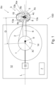
- Figure 1 is a schematic view of an embodiment of an arrangement, a vehicle and method for cable unwinding and winding in an electrically driven vehicle in partial cross-section
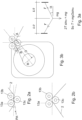
- Figures 2a and 2b are schematic views of a detail of the arrangement shown in Figure 1
- Figures 3a and 3b are schematic views of a geometrical principle.
- the electrically driven vehicle 12 is a mine machine or a construction machine.
- mines - such as underground mines and surface mines - and at other work sites different type of work machines are used.
- the work machine is provided with one or more working device(s).
- the mine machine may be provided with working device(s) for executing mine work task at a work site.
- the mine machine or a construction machine may be e.g.
- rock drilling rig a development drill, a tunneling drilling machine, a surface drilling machine, a bolting or reinforcing vehicle, a rock removal machine, a longhole drill rig, an explosive charging machine, a loader, a transport vehicle, a loading or hauling machine, setting vehicles of gallery arcs or nets, a concrete spraying machine, a crusher or a measuring vehicle.
- the arrangement 100 comprises a cable reel 1 for a cable 2 and arranged in the vehicle 12.
- a centre axis Xr of the cable reel 1 is arranged in vertical position.
- the cable reel 1 may also be arranged other ways: the centre axis Xr may be horizontally arranged, for instance.
- the cable 2 is arranged for supplying electric energy from an electrical network to the vehicle 12.
- the arrangement 100 further comprises a cable guiding arrangement 3 that receives and guides the cable 2.
- the cable guiding arrangement 3 comprises three wheels 13a - 13c that may rotate around their centre axis, respectively.
- the cable guiding arrangement 3 comprises three contacting surfaces 4a, 4b, 4c that are arranged parallel and in a triangle arrangement 5.
- the contacting surfaces 4a, 4b, 4c are on wheels rims.
- the wheels 13a - 13c, or at least one of them is/are rotatable, thus having ability to rotate with movements of the cable 2.
- the centre axis Xw of said wheels are arranged parallel with the normal axis Xn of the triangle arrangement 5. It is to be noted that said normal axis Xn is also normal of the plane of Figure 1 .
- At least one of the wheels 13a - 13c is not rotating, but the cable 2 is arranged to slide over said wheel(s).
- all the wheels 13a - 13c have a same diameter. However, this is not necessary, i.e. there may be wheels of different size.
- At least one of the contacting surfaces 4a, 4b, 4c, or eve all of them, is realized without a wheel.
- a sliding surface as the contacting surface.
- the sliding surface comprises arc-like or semicircle contacting surface made of PTFE.
- the sliding surface(s) may affect to the rotation angle A of the triangle arrangement 5.
- the contacting surfaces 4a, 4b, 4c are arranged and dimensioned such that the cable 2 being arranged between one of said contacting surfaces on its first side and two of said contacting surfaces on its second side bends on a surface of at least one of the contacting surfaces 4a, 4b, 4c.
- the cable guide arrangement 3 comprises a rotational axis Xc that is parallel with the normal axis Xn of the triangle arrangement 5.
- the rotational axis Xc of the cable guide arrangement 3 and the reel axis Xr are arranged in a same direction. In another embodiment, the axes Xc and Xr are oriented in different directions.
- the wheels 13a - 13c and thus the contacting surfaces 4a, 4b, 4c may rotate around said rotational axis Xc.
- said rotational axis Xc is arranged in the middle point of the triangle arrangement 5.
- the rotational axis Xc is arranged somewhat aside of said middle point, but anyway inside the triangle arrangement 5.
- the arrangement further comprises a control arm 6 in which the cable guide arrangement 3 is attached pivotally by the rotational axis Xc.
- the cable guide arrangement 3 may rotate freely in relation to the control arm 6.
- there is a damping means (not shown) that resists the rotational movement of the cable guide arrangement 3.
- the length of the control arm 6 is preferably selected so that the cable guiding arrangement 3 is able to move past the sides of the vehicle 12, as shown in Figure 4b .
- control arm 6 is arranged pivotally to a centre axis Xr of the cable reel so that the rotational axis Xc of the cable wheel arrangement lies at a first distance D from a centre axis Xr of the cable reel.
- the cable guide arrangement 3 may rotate in relation to the cable reel 1 together with the control arm 6.
- control arm 6 may rotate freely in relation to the cable reel 1.
- damping means (not shown) that resists the rotational movement of the control arm 6 in relation to the cable reel 1.
- actuator 14 there is an actuator 14 that is arranged to actively rotate the control arm 6 in relation to the cable reel 1.
- the actuator 14 may be controlled such that the control arm 6 is forced by a predetermined force to be parallel with the longitudinal axis L of the vehicle.
- the actuator 14 is arranged to turn the control arm 6 towards that side.
- the cable may be arranged so that vehicles moving on the same route do not run over the cable.
- the arrangement further comprises a controlling arrangement 7 that is connected to a force measuring system 8, a control arm sensor arrangement 9 and a triangle sensor arrangement 10.
- the force measuring system 8 is provided in at least one - even to all - of the guide surfaces 4a, 4b, 4c and arranged to measure force caused by the cable 2 against said guide surface(s).
- the force measuring system 8 is arranged for measuring force caused to the wheel 13c that is alone on the first side of the cable 2. Based on the measurement, the force measuring system 8 provides an information of force F for the controlling arrangement 7.
- the force measuring system 8 may comprise e.g. a strain gauge, a force transducer, a position transducer, a pressure cell, an eddy-current transducer, etc.
- the control arm sensor arrangement 9 is arranged to detect the direction in which the control arm 6 is pointing in relation to the longitudinal axis L of the electrically driven vehicle 12. Based on the detection, a control arm angle information CA is provided to the controlling arrangement 7.
- the control arm sensor arrangement 9 may comprise e.g. an optical encoder, a resistor potentiometer arrangement, a pulse transducer arrangement etc.
- the triangle sensor arrangement 10 is arranged to evaluate a rotation angle C (shown in Figure 3b ) of the triangle arrangement 5 in respect to the control arm 6. Based on the evaluation, a triangle angle information TA is provided to the controlling arrangement 7.
- the information may have just two values indicating if the cable 2 is contacting just one contacting surface 4a - 4c or all of the contacting surfaces 4a - 4c.
- the triangle sensor arrangement 10 may comprise e.g. an inductive limit switch or a microswitch. If a more accurate information on the rotation angle C is needed, the triangle sensor arrangement 10 may comprise e.g. an optical encoder, a resistor potentiometer arrangement, a pulse transducer arrangement etc.
- the controlling arrangement 7 is arranged to calculate an estimate of forces focusing on the cable 2 based on the force F, the control arm angle information CA and the triangle angle information TA. Referring to Figures 2a and 2b , the controlling arrangement 7 may be arranged to choose between two computation model in the calculation of the forces focused on the cable 2, based on the control arm angle information CA.
- the calculation of the forces focusing in the cable 2 is arranged to be based on a predetermined angle PA that is defined by dimensions of the cable wheel arrangement 3.
- the angle PA is in range of 2° - 5°, for instance 3°.
- Figure 3a is showing a geometrical principle that may be used for the calculation of the force focusing to the cable 2.
- angle " ⁇ " corresponds to the predetermined angle PA
- “mg” corresponds to the force affecting to the measured by the force measuring system 8
- the force focusing to the cable 2 corresponds to "T”.
- the calculation of the forces focusing in the cable 2 is arranged to be based on the rotation angle C and a current cable reel radius R.
- the radius R is measured by a sensor (not shown).
- the radius R is estimated indirectly on basis of turns of the cable on the reel.
- Figure 3b is showing a principle to define an angle A of force in this case.
- the angle A corresponds to angle ⁇ shown in Figure 3a .
- angle A angle C ⁇ angle B , wherein
- Figures 4a - 4c are schematic views of an arrangement and method for cable unwinding and winding in some directions of the cable 2.
- the cable 2 is contacting all the wheels, whereas in Figure 4c the cable 2 is contacting only one of the wheels.
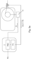
- Figure 5a is a schematic view of a method for cable unwinding and winding in an electrically driven vehicle in partial cross-section
- Figure 5b is showing a detail of Figure 5a .
- the variables for calculating the forces focused on the cable 2 are estimated on basis of force F, control arm angle information CA and triangle angle information TA that are measured and defined as described in this description.
- the method it is measured force caused by the cable against one of the contacting surfaces and created a value for the force F. Also, it is detected the direction in which the control arm 6 is pointing in relation to the longitudinal axis L of the electrically driven vehicle, and provided the control arm angle information CA. Furthermore, it is evaluated a rotation angle C of the triangle arrangement in respect to the control arm 6, and provided the triangle angle information TA. Then, the estimate of forces focused on the cable 2 is provided based on the force F, the control arm angle information CA and the triangle angle information TA. Force setpoint FS is given to the controlling arrangement 7, and a control signal S for controlling a reel motor 11 that is arranged to rotate the cable reel 1 is calculated (force calculation FC).
- a PID controller PBC may be used for providing the control signal S.
- Figure 5b is showing the PID calculation step and controller PBC shown in Figure 5a .
- Value of the force setpoint FS is continuously compared with value of the force calculation FC, and an error value or feedback difference is calculated as the difference of FS and FC.
- the controller PCB attempts to minimize the feedback difference, i.e. difference between FS and FC, by adjusting the control signal S.
- the calculation of the estimation and providing the control signal S may be realized by a controlling arrangement 7 that comprises a processor (CPU) with a memory configured to store program code and dynamic data.
- a processor CPU
- a memory configured to store program code and dynamic data.
- the control signal S is utilized in controlling the reel motor 11.
- the reel motor 11 is controlled such that the cable 2 is under a constant stress, or a certain range of stress, during use of the vehicle 12. In an embodiment, it is controlled torque of the reel motor 11.
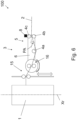
- Figure 6 is a schematic view of an example, useful for understanding the invention, J of the arrangement and method for cable unwinding and winding in an electrically driven vehicle.
- the contacting surfaces 4a, 4b, 4c of the cable guide arrangement 3 are arranged in another direction as the reel axis Xr.
- the reel axis Xr is perpendicular to centre axis of wheels making the contacting surfaces 4a, 4b, 4c.
- the centre axes of wheels are vertically aligned.
- the cable guiding arrangement 3 comprises control surfaces 16 that controls entry of the cable 2 to the triangle arrangement 5.
- the control surfaces 16 are wheels.
- the control arm 6 is arranged to rotate around a rotational axis arranged in close proximity of the control surfaces 16.
- the cable 2 is all the time contacting all the contacting surfaces 4a, 4b, 4c, and the calculation of the forces focusing in the cable 2 is based on a predetermined angle PA that is defined by dimensions of the cable wheel arrangement 3.
- the angle PA is in range of 2° - 5°, for instance 3° .
- the arrangement 100 further comprises a winding device 15 that makes it possible of winding and unwinding the cable 2 without problems even with very wide cable reels 1.
Landscapes
- Engineering & Computer Science (AREA)
- Mechanical Engineering (AREA)
- Power Engineering (AREA)
- Transportation (AREA)
- Life Sciences & Earth Sciences (AREA)
- Sustainable Development (AREA)
- Sustainable Energy (AREA)
- Storing, Repeated Paying-Out, And Re-Storing Of Elongated Articles (AREA)
- Electric Propulsion And Braking For Vehicles (AREA)
- Electric Cable Arrangement Between Relatively Moving Parts (AREA)
Description
- The invention relates to an arrangement for cable unwinding and winding in an electrically driven vehicle.
- The invention further relates to an electrically driven vehicle.
- The invention still further relates to a method for controlling cable winding and unwinding in an electrically driven vehicle.
- Electrically-operated vehicles, such as mine machines, are becoming increasingly common. In this kind of vehicles, controlling winding and unwinding a cable extending from a reel (arranged in the vehicle) to a power source is typically relying on high and varying tension on cable. However, this may cause excessive wearing of the cable.
- The documents
JP H07 33329 A DE 697 33 546 T2 disclose electrical vehicles, comprising a cable winding and unwinding arrangement. - Viewed from a first aspect, there can be provided an arrangement for cable unwinding and winding in an electrically driven vehicle, the arrangement comprising:
- a cable reel for a cable,
- a cable guiding arrangement for receiving and guiding the cable,
- the cable guiding arrangement comprising three contacting surfaces,
arranged parallel and in a triangle arrangement, - the contacting surfaces in the cable guide arrangement being arranged and dimensioned such that the cable arranged between one of the contacting surfaces on its first side and two of the contacting surfaces on its second side bends on a surface of at least one of the contacting surfaces,
- the arrangement further comprising a control arm and a controlling arrangement, the controlling arrangement comprising
- a force measuring system provided in at least one of the contacting surfaces and arranged to measure force caused by the cable against said contacting surface(s), the force measuring system providing a force,
- a control arm sensor arrangement arranged to detect the direction in which the control arm is pointing in relation to the longitudinal axis of the electrically driven vehicle, and for providing a control arm angle information,
- the cable guide arrangement comprising a rotational axis parallel with the normal axis of the triangle arrangement,
- the rotational axis of the cable guide arrangement and the centre axis of the cable reel being arranged in a same direction,
- the cable guide arrangement being attached pivotally in the control arm, and
- the control arm being arranged pivotally to a centre axis of the cable reel so that
- the rotational axis of the cable guide arrangement lies at a first distance from the centre axis of the cable reel and have an ability to rotate in relation to the cable reel, and
- a triangle sensor arrangement being arranged to evaluate a rotation angle of the triangle arrangement in respect to the control arm for providing a triangle angle information,
- Thereby an arrangement controlling reel force with force feedback and thus extending life span of the cable may be achieved. Furthermore, the arrangement may prevent the cable to be run over by the vehicle, which also extends life span of the cable.
- Viewed from a further aspect, there can be provided a vehicle that comprises the arrangement for cable unwinding and winding mentioned above.
- Thereby a vehicle wherein the reel force is controlled with force feedback and thus extending life span of the cable may be achieved.
- Viewed from a still further aspect, there can be provided a method for controlling cable winding and unwinding in an electrically driven vehicle, in which method it is used an arrangement comprising
- a cable reel for a cable,
- a cable guiding arrangement for receiving and guiding the cable,
- the cable guiding arrangement comprising three contacting surfaces arranged parallel and in a triangle arrangement,
- the contacting surfaces in the cable guiding arrangement being arranged and dimensioned such that the cable arranged between one of the contacting surfaces on its first side and two of the contacting surfaces on its second side bends on a surface of at least one of the contacting surfaces, the arrangement further comprising a control arm and a controlling arrangement,
- the cable guiding arrangement comprising a rotational axis parallel with the normal axis of the triangle arrangement, and
- the cable guiding arrangement being attached pivotally by the rotational axis in the control arm, and
- the control arm being arranged pivotally to a centre axis of the cable reel so that
- the rotational axis of the cable guiding arrangement lies at a first distance from a centre axis of the cable reel and have an ability to rotate in relation to the cable reel, the method comprising:
- measuring force caused by the cable against one of the contacting surfaces, thus creating a value for a force,
- detecting the direction in which the control arm is pointing in relation to the longitudinal axis of the electrically driven vehicle, thus providing a control arm angle information,
- evaluating a rotation angle of the triangle arrangement in respect to the control arm, thus providing a triangle angle information, and
- calculating an estimate of forces focused on the cable based on the force, the control arm angle information and on the triangle angle information.
- Thereby a method for controlling reel force with force feedback and thus extending life span of the cable may be achieved. Furthermore, the method may prevent the cable to be run over by the vehicle, which also extends life span of the cable.
- The arrangement and the method are characterised by what is stated in the independent claims. Some other embodiments are characterised by what is stated in the other claims. Inventive embodiments are also disclosed in the specification and drawings of this patent application. The inventive content of the patent application may also be defined in other ways than defined in the following claims. The inventive content may also be formed of several separate inventions, especially if the invention is examined in the light of expressed or implicit sub-tasks or in view of obtained benefits or benefit groups. Some of the definitions contained in the following claims may then be unnecessary in view of the separate inventive ideas. Features of the different embodiments of the invention may, within the scope of the basic inventive idea, be applied to other embodiments.
- In one embodiment, the cable guiding arrangement comprises three wheels, the contacting surfaces being on the wheel rim, and centre axis of said wheels being arranged parallel with the normal axis of the triangle arrangement, and wherein the rotational axis of the cable guiding arrangement is arranged inside the triangle arrangement. An advantage is that the guiding arrangement has a simple structure and, if the wheels are rotating, a low friction to the cable is created.
- In one embodiment, the cable guiding arrangement comprises a rotational axis parallel with the normal axis of the triangle arrangement, and the rotational axis of the cable guide arrangement and the reel axis being arranged in a same direction. An advantage is that the arrangement may have simple structure.
- In one embodiment, the cable guide arrangement is attached pivotally in the control arm, and the control arm is arranged pivotally to a centre axis of the cable reel so that the rotational axis of the cable wheel arrangement lies at a first distance from a centre axis of the cable reel and have an ability to rotate in relation to the cable reel, and a triangle sensor arrangement is arranged to evaluate a rotation angle of the triangle arrangement in respect to the control arm for providing a triangle angle information. An advantage is that the accuracy of the calculations may be increased.
- In one embodiment, the controlling arrangement is arranged to choose between two computation model in the calculation of the forces focused on the cable, based on the control arm angle information. An advantage is that the accuracy of the calculations may be increased.
- In one embodiment, in case the control arm sensor arrangement is detecting the control arm is pointing in a direction where the cable is contacting one of the contacting surfaces only, the calculation of the forces focusing in the cable is arranged to be based on the rotation angle and a current cable reel radius, and in case the control arm sensor arrangement is detecting the control arm is pointing in a direction where the cable is contacting all the contacting surfaces, the calculation of the forces focusing in the cable is arranged to be based on a predetermined angle, said predetermined angle being defined by dimensions of the cable wheel arrangement. An advantage is that the accuracy of the calculations may be increased even further.
- In one embodiment, of method, the cable guiding arrangement comprises a rotational axis parallel with the normal axis of the triangle arrangement, and the cable guiding arrangement is attached pivotally by the rotational axis in the control arm, and the control arm is arranged pivotally to a centre axis of the cable reel so that the rotational axis of the cable guiding arrangement lies at a first distance from a centre axis of the cable reel and have an ability to rotate in relation to the cable reel, the method comprising:
- evaluating a rotation angle of the triangle arrangement in respect to the control arm, thus providing a triangle angle information, and
- calculating an estimate of forces focused on the cable based on the force, the control arm angle information and the triangle angle information. An advantage is that the accuracy of the calculations may be increased even further.
- In one embodiment, the method comprises:
- controlling torque of a reel motor, and
- using calculated forces focusing in the cable in said controlling of torque. An advantage is that the force caused by the reel motor to the cable is directly controlled.
- Some embodiments illustrating the present disclosure are described in more detail in the attached drawings, in which
-
Figure 1 is a schematic view of an arrangement, a vehicle and method for cable unwinding and winding in an electrically driven vehicle in partial cross-section, -
Figures 2a and 2b are schematic views of a detail of the arrangement shown inFigure 1 , -
Figures 3a and 3b are schematic view of a geometrical principles, -
Figures 4a - 4c are schematic views of an arrangement, a vehicle and method for cable unwinding and winding showing some alternative states of the arrangement, -
Figures 5a and5b are a schematic views of an arrangement, a vehicle and method for cable unwinding and winding in an electrically driven vehicle in partial cross-section, and -
Figure 6 is a schematic view of an example, useful for understanding the invention, of the arrangement and method for cable unwinding and winding in an electrically driven vehicle. In the figures, some embodiments are shown simplified for the sake of clarity. Similar parts are marked with the same reference numbers in the figures. -
Figure 1 is a schematic view of an embodiment of an arrangement, a vehicle and method for cable unwinding and winding in an electrically driven vehicle in partial cross-section,Figures 2a and 2b are schematic views of a detail of the arrangement shown inFigure 1 , andFigures 3a and 3b are schematic views of a geometrical principle. - According to an aspect of the invention, the electrically driven
vehicle 12 is a mine machine or a construction machine. In mines - such as underground mines and surface mines - and at other work sites different type of work machines are used. The work machine is provided with one or more working device(s). For instance, the mine machine may be provided with working device(s) for executing mine work task at a work site. The mine machine or a construction machine may be e.g. a rock drilling rig, a development drill, a tunneling drilling machine, a surface drilling machine, a bolting or reinforcing vehicle, a rock removal machine, a longhole drill rig, an explosive charging machine, a loader, a transport vehicle, a loading or hauling machine, setting vehicles of gallery arcs or nets, a concrete spraying machine, a crusher or a measuring vehicle. - The
arrangement 100 comprises acable reel 1 for acable 2 and arranged in thevehicle 12. In an embodiment, such as shown inFigure 1 , a centre axis Xr of thecable reel 1 is arranged in vertical position. However, thecable reel 1 may also be arranged other ways: the centre axis Xr may be horizontally arranged, for instance. - The
cable 2 is arranged for supplying electric energy from an electrical network to thevehicle 12. - The
arrangement 100 further comprises acable guiding arrangement 3 that receives and guides thecable 2. In the embodiment shown inFigure 1 , thecable guiding arrangement 3 comprises threewheels 13a - 13c that may rotate around their centre axis, respectively. - The
cable guiding arrangement 3 comprises three contactingsurfaces triangle arrangement 5. In the embodiment shown inFigure 1 , the contactingsurfaces wheels 13a - 13c, or at least one of them is/are rotatable, thus having ability to rotate with movements of thecable 2. The centre axis Xw of said wheels are arranged parallel with the normal axis Xn of thetriangle arrangement 5. It is to be noted that said normal axis Xn is also normal of the plane ofFigure 1 . - In another embodiment, at least one of the
wheels 13a - 13c is not rotating, but thecable 2 is arranged to slide over said wheel(s). - In the embodiment shown in
Figure 1 , all thewheels 13a - 13c have a same diameter. However, this is not necessary, i.e. there may be wheels of different size. - In an embodiment, at least one of the contacting
surfaces triangle arrangement 5. - The contacting
surfaces cable 2 being arranged between one of said contacting surfaces on its first side and two of said contacting surfaces on its second side bends on a surface of at least one of the contactingsurfaces - The
cable guide arrangement 3 comprises a rotational axis Xc that is parallel with the normal axis Xn of thetriangle arrangement 5. The rotational axis Xc of thecable guide arrangement 3 and the reel axis Xr are arranged in a same direction. In another embodiment, the axes Xc and Xr are oriented in different directions. - The
wheels 13a - 13c and thus the contactingsurfaces triangle arrangement 5. However, in another embodiments, the rotational axis Xc is arranged somewhat aside of said middle point, but anyway inside thetriangle arrangement 5. - The arrangement further comprises a
control arm 6 in which thecable guide arrangement 3 is attached pivotally by the rotational axis Xc. In an embodiment, thecable guide arrangement 3 may rotate freely in relation to thecontrol arm 6. In another embodiment, there is a damping means (not shown) that resists the rotational movement of thecable guide arrangement 3. - The length of the
control arm 6 is preferably selected so that thecable guiding arrangement 3 is able to move past the sides of thevehicle 12, as shown inFigure 4b . - In an embodiment, such as shown in
Figure 1 , thecontrol arm 6 is arranged pivotally to a centre axis Xr of the cable reel so that the rotational axis Xc of the cable wheel arrangement lies at a first distance D from a centre axis Xr of the cable reel. Thus, thecable guide arrangement 3 may rotate in relation to thecable reel 1 together with thecontrol arm 6. - In an embodiment, the
control arm 6 may rotate freely in relation to thecable reel 1. In another embodiment, there is a damping means (not shown) that resists the rotational movement of thecontrol arm 6 in relation to thecable reel 1. In an embodiment, there is an actuator 14 that is arranged to actively rotate thecontrol arm 6 in relation to thecable reel 1. For instance, theactuator 14 may be controlled such that thecontrol arm 6 is forced by a predetermined force to be parallel with the longitudinal axis L of the vehicle. However, sometimes there is need for placing the cable on one of the sides of the vehicle. Then, theactuator 14 is arranged to turn thecontrol arm 6 towards that side. Thus, the cable may be arranged so that vehicles moving on the same route do not run over the cable. - The arrangement further comprises a
controlling arrangement 7 that is connected to aforce measuring system 8, a control arm sensor arrangement 9 and atriangle sensor arrangement 10. - The
force measuring system 8 is provided in at least one - even to all - of the guide surfaces 4a, 4b, 4c and arranged to measure force caused by thecable 2 against said guide surface(s). In the embodiment shown inFigure 1 , theforce measuring system 8 is arranged for measuring force caused to thewheel 13c that is alone on the first side of thecable 2. Based on the measurement, theforce measuring system 8 provides an information of force F for thecontrolling arrangement 7. Theforce measuring system 8 may comprise e.g. a strain gauge, a force transducer, a position transducer, a pressure cell, an eddy-current transducer, etc. - The control arm sensor arrangement 9 is arranged to detect the direction in which the
control arm 6 is pointing in relation to the longitudinal axis L of the electrically drivenvehicle 12. Based on the detection, a control arm angle information CA is provided to thecontrolling arrangement 7. The control arm sensor arrangement 9 may comprise e.g. an optical encoder, a resistor potentiometer arrangement, a pulse transducer arrangement etc. - The
triangle sensor arrangement 10 is arranged to evaluate a rotation angle C (shown inFigure 3b ) of thetriangle arrangement 5 in respect to thecontrol arm 6. Based on the evaluation, a triangle angle information TA is provided to thecontrolling arrangement 7. In an embodiment, the information may have just two values indicating if thecable 2 is contacting just one contactingsurface 4a - 4c or all of the contactingsurfaces 4a - 4c. In this kind of embodiments, thetriangle sensor arrangement 10 may comprise e.g. an inductive limit switch or a microswitch. If a more accurate information on the rotation angle C is needed, thetriangle sensor arrangement 10 may comprise e.g. an optical encoder, a resistor potentiometer arrangement, a pulse transducer arrangement etc. - The
controlling arrangement 7 is arranged to calculate an estimate of forces focusing on thecable 2 based on the force F, the control arm angle information CA and the triangle angle information TA. Referring toFigures 2a and 2b , the controllingarrangement 7 may be arranged to choose between two computation model in the calculation of the forces focused on thecable 2, based on the control arm angle information CA. - In case the control arm angle information CA is indicating that the
control arm 6 is pointing in a direction where thecable 2 is contacting all the contactingsurfaces Figure 2a ), the calculation of the forces focusing in thecable 2 is arranged to be based on a predetermined angle PA that is defined by dimensions of thecable wheel arrangement 3. In an embodiment, the angle PA is in range of 2° - 5°, forinstance 3°.Figure 3a is showing a geometrical principle that may be used for the calculation of the force focusing to thecable 2. InFigure 3a angle "α" corresponds to the predetermined angle PA, "mg" corresponds to the force affecting to the measured by theforce measuring system 8, and the force focusing to thecable 2 corresponds to "T". - In case the control arm angle information CA is indicating that the
control arm 6 is pointing in a direction where thecable 2 is contacting one of the contactingsurfaces Figure 2b ), the calculation of the forces focusing in thecable 2 is arranged to be based on the rotation angle C and a current cable reel radius R. In an embodiment, the radius R is measured by a sensor (not shown). In another embodiment, the radius R is estimated indirectly on basis of turns of the cable on the reel. -
Figure 3b is showing a principle to define an angle A of force in this case. In this case, the angle A corresponds to angle α shown inFigure 3a . Here:
- angle C is evaluated by the
triangle sensor arrangement 10 as previously described, and - angle B = tan-1(R/D), wherein R = radius of cable reel, and D = the first distance.
-
Figures 4a - 4c are schematic views of an arrangement and method for cable unwinding and winding in some directions of thecable 2. InFigures 4a and 4b , thecable 2 is contacting all the wheels, whereas inFigure 4c thecable 2 is contacting only one of the wheels. -
Figure 5a is a schematic view of a method for cable unwinding and winding in an electrically driven vehicle in partial cross-section, andFigure 5b is showing a detail ofFigure 5a . In the method, the variables for calculating the forces focused on thecable 2 are estimated on basis of force F, control arm angle information CA and triangle angle information TA that are measured and defined as described in this description. - In the method, it is measured force caused by the cable against one of the contacting surfaces and created a value for the force F. Also, it is detected the direction in which the
control arm 6 is pointing in relation to the longitudinal axis L of the electrically driven vehicle, and provided the control arm angle information CA. Furthermore, it is evaluated a rotation angle C of the triangle arrangement in respect to thecontrol arm 6, and provided the triangle angle information TA. Then, the estimate of forces focused on thecable 2 is provided based on the force F, the control arm angle information CA and the triangle angle information TA. Force setpoint FS is given to thecontrolling arrangement 7, and a control signal S for controlling areel motor 11 that is arranged to rotate thecable reel 1 is calculated (force calculation FC). A PID controller PBC may be used for providing the control signal S. -
Figure 5b is showing the PID calculation step and controller PBC shown inFigure 5a . Value of the force setpoint FS is continuously compared with value of the force calculation FC, and an error value or feedback difference is calculated as the difference of FS and FC. Based on the feedback difference, the controller PCB applies a correction based on proportional (in Figure Kp = proportional gain), integral (1/s = integration time, Ki = integral gain), and derivative terms (s = derivative time, Kd = derivative gain). The controller PCB attempts to minimize the feedback difference, i.e. difference between FS and FC, by adjusting the control signal S. - The calculation of the estimation and providing the control signal S may be realized by a
controlling arrangement 7 that comprises a processor (CPU) with a memory configured to store program code and dynamic data. - The control signal S is utilized in controlling the
reel motor 11. In an embodiment, thereel motor 11 is controlled such that thecable 2 is under a constant stress, or a certain range of stress, during use of thevehicle 12. In an embodiment, it is controlled torque of thereel motor 11. -
Figure 6 is a schematic view of an example, useful for understanding the invention, J of the arrangement and method for cable unwinding and winding in an electrically driven vehicle. - According to an aspect, the contacting
surfaces cable guide arrangement 3 are arranged in another direction as the reel axis Xr. In the embodiment shown inFigure 6 , the reel axis Xr is perpendicular to centre axis of wheels making the contactingsurfaces - The
cable guiding arrangement 3 comprisescontrol surfaces 16 that controls entry of thecable 2 to thetriangle arrangement 5. In the embodiment shown inFigure 6 , the control surfaces 16 are wheels. Thecontrol arm 6 is arranged to rotate around a rotational axis arranged in close proximity of the control surfaces 16. - Due to the control surfaces 16, the
cable 2 is all the time contacting all the contactingsurfaces cable 2 is based on a predetermined angle PA that is defined by dimensions of thecable wheel arrangement 3. In an embodiment, the angle PA is in range of 2° - 5°, forinstance 3° . - The
arrangement 100 further comprises a windingdevice 15 that makes it possible of winding and unwinding thecable 2 without problems even with verywide cable reels 1. - The drawings and the related description are only intended to illustrate the idea of the invention. The invention may vary in detail within the scope of the inventive idea defined in the following claims.
-
- 1
- cable reel
- 2
- cable
- 3
- cable guiding arrangement
- 4a-4c
- contacting surface
- 5
- triangle arrangement
- 6
- control arm
- 7
- controlling arrangement
- 8
- force measuring system
- 9
- control arm sensor arrangement
- 10
- triangle sensor arrangement
- 11
- reel motor
- 12
- vehicle
- 13a-13c
- wheel
- 14
- actuator
- 15
- winding device
- 16
- control surfaces
- 100
- arrangement
- A
- angle of force
- C
- rotation angle
- CA
- angle information
- D
- first distance
- F
- force
- FC
- force calculation
- FS
- force setpoint
- L
- longitudinal axis
- PA
- predetermined angle
- PBC
- PID controller
- R
- radius of reel
- S
- control signal
- TA
- arm angle information
- Xc
- rotational axis of cable guiding arrangement
- Xr
- centre axis of cable reel
- Xn
- normal axis of triangle arrangement
- Xw
- centre axis of wheel
Claims (12)
- An arrangement (100) for cable unwinding and winding in an electrically driven vehicle, the arrangement comprising:- a cable reel (1) for a cable (2),- a cable guide arrangement (3) for receiving and guiding the cable (2),- the cable guide arrangement (3) comprising three contacting surfaces (4a, 4b, 4c),
arranged parallel and in a triangle arrangement (5),- the contacting surfaces (4a, 4b, 4c) in the cable guide arrangement (3) being arranged and dimensioned such that the cable (2) arranged between one of the contacting surfaces on its first side and two of the contacting surfaces on its second side bends on a surface of at least one of the contacting surfaces (4a, 4b, 4c),- the arrangement further comprising a control arm (6) and a controlling arrangement (7), the controlling arrangement (7) comprisingwherein- a force measuring system (8) provided in at least one of the contacting surfaces (4a, 4b, 4c) and arranged to measure force caused by the cable against said contacting surface(s), the force measuring system (8) providing a force (F),- a control arm sensor arrangement (9) arranged to detect the direction in which the control arm (6) is pointing in relation to the longitudinal axis (L) of the electrically driven vehicle, and for providing a control arm angle information (CA),- the cable guide arrangement (3) comprises a rotational axis (Xc) parallel with the normal axis (Xn) of the triangle arrangement (5),- the rotational axis (Xc) of the cable guide arrangement and the centre axis (Xr) of the cable reel are arranged in a same direction,- the cable guide arrangement (3) is attached pivotally in the control arm (6), and- the control arm (6) is arranged pivotally to a centre axis (Xr) of the cable reel so that- the rotational axis (Xc) of the cable guide arrangement lies at a first distance (D) from the centre axis (Xr) of the cable reel and have an ability to rotate in relation to the cable reel, and- a triangle sensor arrangement (10) is arranged to evaluate a rotation angle (A) of the triangle arrangement (5) in respect to the control arm (6) for providing a triangle angle information (TA), and whereinthe controlling arrangement (7) is arranged to calculate an estimate of forces focusing on the cable (2) based on the force (F), the control arm angle information (CA) and the triangle angle information (TA). - The arrangement as claimed in claim 1, wherein the cable guiding arrangement (3) comprises three wheels (13a - 13c), the contacting surfaces (4a, 4b, 4c) being on the wheel rim,centre axis (Xw) of said wheels being arranged parallel with the normal axis (Xn) of the triangle arrangement (5), and whereinthe rotational axis (Xc) of the cable guiding arrangement is arranged inside the triangle arrangement (5).
- The arrangement as claimed in claim 1 or 2, wherein the controlling arrangement (7) is arranged to choose between two computation model in the calculation of the forces focused on the cable (2), based on the control arm angle information (CA) .
- The arrangement as claimed in claim 3, wherein in case the control arm sensor arrangement (9) is detecting the control arm (6) is pointing in a direction where the cable (2) is contacting one of the contacting surfaces (4a, 4b, 4c) only, the calculation of the forces focusing in the cable (2) is arranged to be based on the rotation angle (A) and a current cable reel radius (R), and wherein
in case the control arm sensor arrangement (9) is detecting the control arm (6) is pointing in a direction where the cable (2) is contacting all the contacting surfaces (4a, 4b, 4c), the calculation of the forces focusing in the cable (2) is arranged to be based on a predetermined angle (PA), said predetermined angle (PA) being defined by dimensions of the cable wheel arrangement (3). - The arrangement as claimed in claim 1 or 2, wherein the contacting surfaces (4a, 4b, 4c) of the cable guide arrangement (3) are arranged in another direction as the reel axis (Xr).
- An electrically driven vehicle (12), comprising the arrangement claimed in any of the preceding claims.
- The vehicle as claimed in claim 6, being a mine machine.
- The vehicle as claimed in claim 6, being a construction machine.
- Method for controlling cable (2) winding and unwinding in an electrically driven vehicle, in which method it is used an arrangement comprising- a cable reel (1) for a cable (2),- a cable guiding arrangement (3) for receiving and guiding the cable (2),- the cable guiding arrangement (3) comprising three contacting surfaces (4a, 4b, 4c) arranged parallel and in a triangle arrangement (5),- the contacting surfaces (4a, 4b, 4c) in the cable guiding arrangement (3) being arranged and dimensioned such that the cable arranged between one of the contacting surfaces on its first side and two of the contacting surfaces on its second side bends on a surface of at least one of the contacting surfaces (4a, 4b, 4c),- the arrangement further comprising a control arm (6) and a controlling arrangement (7), wherein- the cable guiding arrangement (3) comprises a rotational axis (Xc) parallel with the normal axis (Xn) of the triangle arrangement (5), and- the cable guiding arrangement (3) is attached pivotally by the rotational axis (Xc) in the control arm (6), and- the control arm (6) is arranged pivotally to a centre axis (Xr) of the cable reel so that- the rotational axis (Xc) of the cable guiding arrangement lies at a first distance (D) from a centre axis (Xr) of the cable reel and have an ability to rotate in relation to the cable reel, the method comprising:- measuring force caused by the cable against one of the contacting surfaces, thus creating a value for a force (F),- detecting the direction in which the control arm (6) is pointing in relation to the longitudinal axis (L) of the electrically driven vehicle, thus providing a control arm angle information (CA),- evaluating a rotation angle (C) of the triangle arrangement in respect to the control arm (6), thus providing a triangle angle information (TA), and- calculating an estimate of forces focused on the cable (2) based on the force (F), the control arm angle information (CA) and the triangle angle information (TA).
- The method as claimed in claim 9, comprising choosing between two computation model in the calculation of the forces focused on the cable (2), based on the control arm angle information (CA).
- The method as claimed in claim 10, wherein in case the control arm (6) is pointing in a direction where the cable (2) is contacting one of the contacting surfaces (4a, 4b, 4c) only:calculating the forces focusing in the cable (2) based on the rotation angle (C) and a current cable reel radius (R), and whereinin case the control arm (6) is pointing in a direction where the cable (2) is contacting all the contacting surfaces (4a, 4b, 4c):
calculating the forces focusing in the cable (2) based on a predetermined angle (PA), said predetermined angle (PA) being defined by dimensions of the cable wheel arrangement (3) . - The method as claimed in any of the claims 9 - 11, comprising controlling torque of a reel motor (11), and using calculated forces focusing in the cable (2) in said controlling of torque.
Priority Applications (7)
| Application Number | Priority Date | Filing Date | Title |
|---|---|---|---|
| PL20154047.3T PL3859925T3 (en) | 2020-01-28 | 2020-01-28 | Arrangement, vehicle and method |
| EP20154047.3A EP3859925B1 (en) | 2020-01-28 | 2020-01-28 | Arrangement, vehicle and method |
| FIEP20154047.3T FI3859925T3 (en) | 2020-01-28 | 2020-01-28 | Arrangement, vehicle and method |
| AU2021215007A AU2021215007B2 (en) | 2020-01-28 | 2021-01-28 | Arrangement, vehicle and method for cable winding and unwinding |
| CA3163991A CA3163991A1 (en) | 2020-01-28 | 2021-01-28 | Arrangement, vehicle and method for cable winding and unwinding |
| CN202180009936.9A CN115004495A (en) | 2020-01-28 | 2021-01-28 | Apparatus, vehicle and method for cable winding and unwinding |
| PCT/EP2021/052031 WO2021152042A1 (en) | 2020-01-28 | 2021-01-28 | Arrangement, vehicle and method for cable winding and unwinding |
Applications Claiming Priority (1)
| Application Number | Priority Date | Filing Date | Title |
|---|---|---|---|
| EP20154047.3A EP3859925B1 (en) | 2020-01-28 | 2020-01-28 | Arrangement, vehicle and method |
Publications (2)
| Publication Number | Publication Date |
|---|---|
| EP3859925A1 EP3859925A1 (en) | 2021-08-04 |
| EP3859925B1 true EP3859925B1 (en) | 2023-09-06 |
Family
ID=69571759
Family Applications (1)
| Application Number | Title | Priority Date | Filing Date |
|---|---|---|---|
| EP20154047.3A Active EP3859925B1 (en) | 2020-01-28 | 2020-01-28 | Arrangement, vehicle and method |
Country Status (7)
| Country | Link |
|---|---|
| EP (1) | EP3859925B1 (en) |
| CN (1) | CN115004495A (en) |
| AU (1) | AU2021215007B2 (en) |
| CA (1) | CA3163991A1 (en) |
| FI (1) | FI3859925T3 (en) |
| PL (1) | PL3859925T3 (en) |
| WO (1) | WO2021152042A1 (en) |
Families Citing this family (4)
| Publication number | Priority date | Publication date | Assignee | Title |
|---|---|---|---|---|
| US20230063279A1 (en) * | 2021-09-02 | 2023-03-02 | Reel Power Licensing Corp. | Oscillating traverse coiler |
| EP4180378A1 (en) * | 2021-11-16 | 2023-05-17 | Kingfisher International Products Limited | Guide and feeder system for a windable material |
| CN116853907A (en) * | 2023-06-28 | 2023-10-10 | 中联重科土方机械有限公司 | Method for controlling cable retraction and retraction, cable retraction and retraction device and controller |
| CN120697596B (en) * | 2025-07-10 | 2026-01-23 | 利嘉新能源有限公司 | A smart charging pile |
Family Cites Families (7)
| Publication number | Priority date | Publication date | Assignee | Title |
|---|---|---|---|---|
| JP3050349B2 (en) * | 1993-02-26 | 2000-06-12 | スズキ株式会社 | Cable winding device |
| JP3022076B2 (en) * | 1993-07-21 | 2000-03-15 | スズキ株式会社 | Cable condition control device for remotely controlled vehicles |
| FI100039B (en) * | 1996-02-02 | 1997-08-29 | Tamrock Loaders Oy | Method and arrangement for controlling the unrolling and unloading of a cable of an electric vehicle |
| RU2543175C2 (en) * | 2010-02-18 | 2015-02-27 | Симпелькамп Машинен-Унд Анлагенбау Гмбх | Device and method for manufacturing belt conveyors with steel cable having core |
| DE102011080082A1 (en) * | 2011-07-29 | 2013-01-31 | Kiekert Ag | Bearing device with cable guide for an electric vehicle |
| GB2497666A (en) * | 2011-12-13 | 2013-06-19 | Joy Mm Delaware Inc | Swinging sheave bracket with force control |
| DE202013104456U1 (en) * | 2013-10-01 | 2013-10-14 | Bernhard Kummert | Cable storage device |
-
2020
- 2020-01-28 EP EP20154047.3A patent/EP3859925B1/en active Active
- 2020-01-28 FI FIEP20154047.3T patent/FI3859925T3/en active
- 2020-01-28 PL PL20154047.3T patent/PL3859925T3/en unknown
-
2021
- 2021-01-28 CN CN202180009936.9A patent/CN115004495A/en active Pending
- 2021-01-28 CA CA3163991A patent/CA3163991A1/en active Pending
- 2021-01-28 AU AU2021215007A patent/AU2021215007B2/en active Active
- 2021-01-28 WO PCT/EP2021/052031 patent/WO2021152042A1/en not_active Ceased
Also Published As
| Publication number | Publication date |
|---|---|
| CN115004495A (en) | 2022-09-02 |
| FI3859925T3 (en) | 2023-10-02 |
| CA3163991A1 (en) | 2021-08-05 |
| EP3859925A1 (en) | 2021-08-04 |
| WO2021152042A1 (en) | 2021-08-05 |
| PL3859925T3 (en) | 2023-12-27 |
| AU2021215007B2 (en) | 2026-02-12 |
| AU2021215007A1 (en) | 2022-08-04 |
Similar Documents
| Publication | Publication Date | Title |
|---|---|---|
| EP3859925B1 (en) | Arrangement, vehicle and method | |
| US9389130B2 (en) | Assembly, system and method for cable tension measurement | |
| US8612175B2 (en) | Measurement device and a system and method for using the same | |
| KR20130093545A (en) | Method for detecting a torque and industrial robot | |
| CN102020199A (en) | System for determining the load mass of a load suspended on a lifting rope of a crane | |
| EP2821188A1 (en) | Position control device using joystick | |
| MX2011010596A (en) | High tension cable measurement system and assembly. | |
| EP3417144B1 (en) | Systems and methods for measuring bending, weight on bit and torque on bit while drilling | |
| CN105452148A (en) | Smart motor brake for length and angle sensors in cranes | |
| AU2019205026B2 (en) | Cable handling system for longwall mining machines | |
| CN101774509B (en) | System for automatically controlling distance between object and ground and control method thereof | |
| CN110244705A (en) | A kind of the walking calibrating installation and calibration method of automatic guided vehicle | |
| Bi et al. | Study on theory and methods of payload online estimation for cable shovels | |
| KR101058198B1 (en) | Loading Automation Experiment Device of Wheel Loader | |
| JP7056801B2 (en) | Construction method of rotary pile, manufacturing method of pile group, pile group, construction management device of rotary pile, construction management system of rotary pile | |
| JP2004157088A (en) | Method and apparatus for measuring screw characteristics | |
| EP2815993B1 (en) | Splice monitoring system for conveyor belts in mining industry | |
| EA043361B1 (en) | DEVICE, VEHICLE AND METHOD FOR REWINDING AND UNWINDING CABLE | |
| KR102868515B1 (en) | System for predicting life cycle of crane | |
| CN121048026B (en) | Three-Circle Pipe Jacking Machine Torque Correction Method and Device | |
| CN115605423B (en) | Method for operating a lifting device and lifting device for carrying out the method | |
| JPH0474651B2 (en) | ||
| KR101804770B1 (en) | Navi-guider, mobile robot using navi-guider and guide method for mobile robot | |
| US20200370420A1 (en) | Drill head position determination system | |
| CN121781903A (en) | Drilling depth control system, drilling machine and drilling depth control method |
Legal Events
| Date | Code | Title | Description |
|---|---|---|---|
| PUAI | Public reference made under article 153(3) epc to a published international application that has entered the european phase |
Free format text: ORIGINAL CODE: 0009012 |
|
| STAA | Information on the status of an ep patent application or granted ep patent |
Free format text: STATUS: THE APPLICATION HAS BEEN PUBLISHED |
|
| AK | Designated contracting states |
Kind code of ref document: A1 Designated state(s): AL AT BE BG CH CY CZ DE DK EE ES FI FR GB GR HR HU IE IS IT LI LT LU LV MC MK MT NL NO PL PT RO RS SE SI SK SM TR |
|
| STAA | Information on the status of an ep patent application or granted ep patent |
Free format text: STATUS: REQUEST FOR EXAMINATION WAS MADE |
|
| 17P | Request for examination filed |
Effective date: 20220204 |
|
| RBV | Designated contracting states (corrected) |
Designated state(s): AL AT BE BG CH CY CZ DE DK EE ES FI FR GB GR HR HU IE IS IT LI LT LU LV MC MK MT NL NO PL PT RO RS SE SI SK SM TR |
|
| REG | Reference to a national code |
Ref country code: DE Ref legal event code: R079 Free format text: PREVIOUS MAIN CLASS: H02G0011000000 Ipc: B65H0059380000 Ref document number: 602020016985 Country of ref document: DE |
|
| GRAP | Despatch of communication of intention to grant a patent |
Free format text: ORIGINAL CODE: EPIDOSNIGR1 |
|
| STAA | Information on the status of an ep patent application or granted ep patent |
Free format text: STATUS: GRANT OF PATENT IS INTENDED |
|
| RIC1 | Information provided on ipc code assigned before grant |
Ipc: B60L 9/00 20060101ALI20230222BHEP Ipc: B65H 75/42 20060101ALI20230222BHEP Ipc: H02G 11/02 20060101ALI20230222BHEP Ipc: B60L 5/00 20060101ALI20230222BHEP Ipc: B66D 1/48 20060101ALI20230222BHEP Ipc: B66D 1/38 20060101ALI20230222BHEP Ipc: B65H 75/44 20060101ALI20230222BHEP Ipc: B65H 59/38 20060101AFI20230222BHEP |
|
| INTG | Intention to grant announced |
Effective date: 20230329 |
|
| P01 | Opt-out of the competence of the unified patent court (upc) registered |
Effective date: 20230603 |
|
| GRAS | Grant fee paid |
Free format text: ORIGINAL CODE: EPIDOSNIGR3 |
|
| GRAA | (expected) grant |
Free format text: ORIGINAL CODE: 0009210 |
|
| STAA | Information on the status of an ep patent application or granted ep patent |
Free format text: STATUS: THE PATENT HAS BEEN GRANTED |
|
| AK | Designated contracting states |
Kind code of ref document: B1 Designated state(s): AL AT BE BG CH CY CZ DE DK EE ES FI FR GB GR HR HU IE IS IT LI LT LU LV MC MK MT NL NO PL PT RO RS SE SI SK SM TR |
|
| REG | Reference to a national code |
Ref country code: GB Ref legal event code: FG4D |
|
| REG | Reference to a national code |
Ref country code: CH Ref legal event code: EP |
|
| REG | Reference to a national code |
Ref country code: IE Ref legal event code: FG4D |
|
| REG | Reference to a national code |
Ref country code: DE Ref legal event code: R096 Ref document number: 602020016985 Country of ref document: DE |
|
| REG | Reference to a national code |
Ref country code: FI Ref legal event code: FGE |
|
| REG | Reference to a national code |
Ref country code: SE Ref legal event code: TRGR |
|
| REG | Reference to a national code |
Ref country code: LT Ref legal event code: MG9D |
|
| REG | Reference to a national code |
Ref country code: NL Ref legal event code: MP Effective date: 20230906 |
|
| PG25 | Lapsed in a contracting state [announced via postgrant information from national office to epo] |
Ref country code: GR Free format text: LAPSE BECAUSE OF FAILURE TO SUBMIT A TRANSLATION OF THE DESCRIPTION OR TO PAY THE FEE WITHIN THE PRESCRIBED TIME-LIMIT Effective date: 20231207 |
|
| PG25 | Lapsed in a contracting state [announced via postgrant information from national office to epo] |
Ref country code: RS Free format text: LAPSE BECAUSE OF FAILURE TO SUBMIT A TRANSLATION OF THE DESCRIPTION OR TO PAY THE FEE WITHIN THE PRESCRIBED TIME-LIMIT Effective date: 20230906 Ref country code: NO Free format text: LAPSE BECAUSE OF FAILURE TO SUBMIT A TRANSLATION OF THE DESCRIPTION OR TO PAY THE FEE WITHIN THE PRESCRIBED TIME-LIMIT Effective date: 20231206 Ref country code: LV Free format text: LAPSE BECAUSE OF FAILURE TO SUBMIT A TRANSLATION OF THE DESCRIPTION OR TO PAY THE FEE WITHIN THE PRESCRIBED TIME-LIMIT Effective date: 20230906 Ref country code: LT Free format text: LAPSE BECAUSE OF FAILURE TO SUBMIT A TRANSLATION OF THE DESCRIPTION OR TO PAY THE FEE WITHIN THE PRESCRIBED TIME-LIMIT Effective date: 20230906 Ref country code: HR Free format text: LAPSE BECAUSE OF FAILURE TO SUBMIT A TRANSLATION OF THE DESCRIPTION OR TO PAY THE FEE WITHIN THE PRESCRIBED TIME-LIMIT Effective date: 20230906 Ref country code: GR Free format text: LAPSE BECAUSE OF FAILURE TO SUBMIT A TRANSLATION OF THE DESCRIPTION OR TO PAY THE FEE WITHIN THE PRESCRIBED TIME-LIMIT Effective date: 20231207 |
|
| REG | Reference to a national code |
Ref country code: AT Ref legal event code: MK05 Ref document number: 1608323 Country of ref document: AT Kind code of ref document: T Effective date: 20230906 |
|
| PG25 | Lapsed in a contracting state [announced via postgrant information from national office to epo] |
Ref country code: NL Free format text: LAPSE BECAUSE OF FAILURE TO SUBMIT A TRANSLATION OF THE DESCRIPTION OR TO PAY THE FEE WITHIN THE PRESCRIBED TIME-LIMIT Effective date: 20230906 |
|
| PG25 | Lapsed in a contracting state [announced via postgrant information from national office to epo] |
Ref country code: IS Free format text: LAPSE BECAUSE OF FAILURE TO SUBMIT A TRANSLATION OF THE DESCRIPTION OR TO PAY THE FEE WITHIN THE PRESCRIBED TIME-LIMIT Effective date: 20240106 |
|
| PG25 | Lapsed in a contracting state [announced via postgrant information from national office to epo] |
Ref country code: AT Free format text: LAPSE BECAUSE OF FAILURE TO SUBMIT A TRANSLATION OF THE DESCRIPTION OR TO PAY THE FEE WITHIN THE PRESCRIBED TIME-LIMIT Effective date: 20230906 |
|
| PG25 | Lapsed in a contracting state [announced via postgrant information from national office to epo] |
Ref country code: ES Free format text: LAPSE BECAUSE OF FAILURE TO SUBMIT A TRANSLATION OF THE DESCRIPTION OR TO PAY THE FEE WITHIN THE PRESCRIBED TIME-LIMIT Effective date: 20230906 |
|
| PG25 | Lapsed in a contracting state [announced via postgrant information from national office to epo] |
Ref country code: SM Free format text: LAPSE BECAUSE OF FAILURE TO SUBMIT A TRANSLATION OF THE DESCRIPTION OR TO PAY THE FEE WITHIN THE PRESCRIBED TIME-LIMIT Effective date: 20230906 Ref country code: RO Free format text: LAPSE BECAUSE OF FAILURE TO SUBMIT A TRANSLATION OF THE DESCRIPTION OR TO PAY THE FEE WITHIN THE PRESCRIBED TIME-LIMIT Effective date: 20230906 Ref country code: IS Free format text: LAPSE BECAUSE OF FAILURE TO SUBMIT A TRANSLATION OF THE DESCRIPTION OR TO PAY THE FEE WITHIN THE PRESCRIBED TIME-LIMIT Effective date: 20240106 Ref country code: ES Free format text: LAPSE BECAUSE OF FAILURE TO SUBMIT A TRANSLATION OF THE DESCRIPTION OR TO PAY THE FEE WITHIN THE PRESCRIBED TIME-LIMIT Effective date: 20230906 Ref country code: EE Free format text: LAPSE BECAUSE OF FAILURE TO SUBMIT A TRANSLATION OF THE DESCRIPTION OR TO PAY THE FEE WITHIN THE PRESCRIBED TIME-LIMIT Effective date: 20230906 Ref country code: AT Free format text: LAPSE BECAUSE OF FAILURE TO SUBMIT A TRANSLATION OF THE DESCRIPTION OR TO PAY THE FEE WITHIN THE PRESCRIBED TIME-LIMIT Effective date: 20230906 Ref country code: PT Free format text: LAPSE BECAUSE OF FAILURE TO SUBMIT A TRANSLATION OF THE DESCRIPTION OR TO PAY THE FEE WITHIN THE PRESCRIBED TIME-LIMIT Effective date: 20240108 Ref country code: SK Free format text: LAPSE BECAUSE OF FAILURE TO SUBMIT A TRANSLATION OF THE DESCRIPTION OR TO PAY THE FEE WITHIN THE PRESCRIBED TIME-LIMIT Effective date: 20230906 |
|
| PG25 | Lapsed in a contracting state [announced via postgrant information from national office to epo] |
Ref country code: IT Free format text: LAPSE BECAUSE OF FAILURE TO SUBMIT A TRANSLATION OF THE DESCRIPTION OR TO PAY THE FEE WITHIN THE PRESCRIBED TIME-LIMIT Effective date: 20230906 |
|
| REG | Reference to a national code |
Ref country code: DE Ref legal event code: R097 Ref document number: 602020016985 Country of ref document: DE |
|
| PG25 | Lapsed in a contracting state [announced via postgrant information from national office to epo] |
Ref country code: DK Free format text: LAPSE BECAUSE OF FAILURE TO SUBMIT A TRANSLATION OF THE DESCRIPTION OR TO PAY THE FEE WITHIN THE PRESCRIBED TIME-LIMIT Effective date: 20230906 |
|
| PLBE | No opposition filed within time limit |
Free format text: ORIGINAL CODE: 0009261 |
|
| STAA | Information on the status of an ep patent application or granted ep patent |
Free format text: STATUS: NO OPPOSITION FILED WITHIN TIME LIMIT |
|
| PG25 | Lapsed in a contracting state [announced via postgrant information from national office to epo] |
Ref country code: DK Free format text: LAPSE BECAUSE OF FAILURE TO SUBMIT A TRANSLATION OF THE DESCRIPTION OR TO PAY THE FEE WITHIN THE PRESCRIBED TIME-LIMIT Effective date: 20230906 Ref country code: SI Free format text: LAPSE BECAUSE OF FAILURE TO SUBMIT A TRANSLATION OF THE DESCRIPTION OR TO PAY THE FEE WITHIN THE PRESCRIBED TIME-LIMIT Effective date: 20230906 |
|
| 26N | No opposition filed |
Effective date: 20240607 |
|
| PG25 | Lapsed in a contracting state [announced via postgrant information from national office to epo] |
Ref country code: MC Free format text: LAPSE BECAUSE OF FAILURE TO SUBMIT A TRANSLATION OF THE DESCRIPTION OR TO PAY THE FEE WITHIN THE PRESCRIBED TIME-LIMIT Effective date: 20230906 |
|
| PG25 | Lapsed in a contracting state [announced via postgrant information from national office to epo] |
Ref country code: MC Free format text: LAPSE BECAUSE OF FAILURE TO SUBMIT A TRANSLATION OF THE DESCRIPTION OR TO PAY THE FEE WITHIN THE PRESCRIBED TIME-LIMIT Effective date: 20230906 |
|
| REG | Reference to a national code |
Ref country code: CH Ref legal event code: PL |
|
| PG25 | Lapsed in a contracting state [announced via postgrant information from national office to epo] |
Ref country code: LU Free format text: LAPSE BECAUSE OF NON-PAYMENT OF DUE FEES Effective date: 20240128 |
|
| GBPC | Gb: european patent ceased through non-payment of renewal fee |
Effective date: 20240128 |
|
| PG25 | Lapsed in a contracting state [announced via postgrant information from national office to epo] |
Ref country code: LU Free format text: LAPSE BECAUSE OF NON-PAYMENT OF DUE FEES Effective date: 20240128 |
|
| PG25 | Lapsed in a contracting state [announced via postgrant information from national office to epo] |
Ref country code: GB Free format text: LAPSE BECAUSE OF NON-PAYMENT OF DUE FEES Effective date: 20240128 |
|
| PG25 | Lapsed in a contracting state [announced via postgrant information from national office to epo] |
Ref country code: BE Free format text: LAPSE BECAUSE OF NON-PAYMENT OF DUE FEES Effective date: 20240131 |
|
| PG25 | Lapsed in a contracting state [announced via postgrant information from national office to epo] |
Ref country code: CH Free format text: LAPSE BECAUSE OF NON-PAYMENT OF DUE FEES Effective date: 20240131 |
|
| PG25 | Lapsed in a contracting state [announced via postgrant information from national office to epo] |
Ref country code: GB Free format text: LAPSE BECAUSE OF NON-PAYMENT OF DUE FEES Effective date: 20240128 Ref country code: CH Free format text: LAPSE BECAUSE OF NON-PAYMENT OF DUE FEES Effective date: 20240131 Ref country code: BE Free format text: LAPSE BECAUSE OF NON-PAYMENT OF DUE FEES Effective date: 20240131 |
|
| REG | Reference to a national code |
Ref country code: BE Ref legal event code: MM Effective date: 20240131 |
|
| PG25 | Lapsed in a contracting state [announced via postgrant information from national office to epo] |
Ref country code: BG Free format text: LAPSE BECAUSE OF FAILURE TO SUBMIT A TRANSLATION OF THE DESCRIPTION OR TO PAY THE FEE WITHIN THE PRESCRIBED TIME-LIMIT Effective date: 20230906 |
|
| PG25 | Lapsed in a contracting state [announced via postgrant information from national office to epo] |
Ref country code: BG Free format text: LAPSE BECAUSE OF FAILURE TO SUBMIT A TRANSLATION OF THE DESCRIPTION OR TO PAY THE FEE WITHIN THE PRESCRIBED TIME-LIMIT Effective date: 20230906 |
|
| PG25 | Lapsed in a contracting state [announced via postgrant information from national office to epo] |
Ref country code: IE Free format text: LAPSE BECAUSE OF NON-PAYMENT OF DUE FEES Effective date: 20240128 |
|
| PG25 | Lapsed in a contracting state [announced via postgrant information from national office to epo] |
Ref country code: IE Free format text: LAPSE BECAUSE OF NON-PAYMENT OF DUE FEES Effective date: 20240128 |
|
| PG25 | Lapsed in a contracting state [announced via postgrant information from national office to epo] |
Ref country code: CY Free format text: LAPSE BECAUSE OF FAILURE TO SUBMIT A TRANSLATION OF THE DESCRIPTION OR TO PAY THE FEE WITHIN THE PRESCRIBED TIME-LIMIT; INVALID AB INITIO Effective date: 20200128 |
|
| PG25 | Lapsed in a contracting state [announced via postgrant information from national office to epo] |
Ref country code: HU Free format text: LAPSE BECAUSE OF FAILURE TO SUBMIT A TRANSLATION OF THE DESCRIPTION OR TO PAY THE FEE WITHIN THE PRESCRIBED TIME-LIMIT; INVALID AB INITIO Effective date: 20200128 |
|
| PG25 | Lapsed in a contracting state [announced via postgrant information from national office to epo] |
Ref country code: TR Free format text: LAPSE BECAUSE OF FAILURE TO SUBMIT A TRANSLATION OF THE DESCRIPTION OR TO PAY THE FEE WITHIN THE PRESCRIBED TIME-LIMIT Effective date: 20230906 |
|
| PGFP | Annual fee paid to national office [announced via postgrant information from national office to epo] |
Ref country code: FI Payment date: 20251230 Year of fee payment: 7 |
|
| PGFP | Annual fee paid to national office [announced via postgrant information from national office to epo] |
Ref country code: FR Payment date: 20251222 Year of fee payment: 7 |
|
| PGFP | Annual fee paid to national office [announced via postgrant information from national office to epo] |
Ref country code: SE Payment date: 20251210 Year of fee payment: 7 |
|
| PGFP | Annual fee paid to national office [announced via postgrant information from national office to epo] |
Ref country code: CZ Payment date: 20251229 Year of fee payment: 7 |
|
| PGFP | Annual fee paid to national office [announced via postgrant information from national office to epo] |
Ref country code: PL Payment date: 20251212 Year of fee payment: 7 |
|
| PGFP | Annual fee paid to national office [announced via postgrant information from national office to epo] |
Ref country code: DE Payment date: 20251203 Year of fee payment: 7 |