EP3859908A1 - Plug-in connector element and plug-in connector for high-voltage applications - Google Patents
Plug-in connector element and plug-in connector for high-voltage applications Download PDFInfo
- Publication number
- EP3859908A1 EP3859908A1 EP21152086.1A EP21152086A EP3859908A1 EP 3859908 A1 EP3859908 A1 EP 3859908A1 EP 21152086 A EP21152086 A EP 21152086A EP 3859908 A1 EP3859908 A1 EP 3859908A1
- Authority
- EP
- European Patent Office
- Prior art keywords
- plug
- contact
- connector
- electrically conductive
- mating
- Prior art date
- Legal status (The legal status is an assumption and is not a legal conclusion. Google has not performed a legal analysis and makes no representation as to the accuracy of the status listed.)
- Granted
Links
Images



Classifications
-
- H—ELECTRICITY
- H01—ELECTRIC ELEMENTS
- H01R—ELECTRICALLY-CONDUCTIVE CONNECTIONS; STRUCTURAL ASSOCIATIONS OF A PLURALITY OF MUTUALLY-INSULATED ELECTRICAL CONNECTING ELEMENTS; COUPLING DEVICES; CURRENT COLLECTORS
- H01R13/00—Details of coupling devices of the kinds covered by groups H01R12/70 or H01R24/00 - H01R33/00
- H01R13/44—Means for preventing access to live contacts
- H01R13/447—Shutter or cover plate
-
- H—ELECTRICITY
- H01—ELECTRIC ELEMENTS
- H01R—ELECTRICALLY-CONDUCTIVE CONNECTIONS; STRUCTURAL ASSOCIATIONS OF A PLURALITY OF MUTUALLY-INSULATED ELECTRICAL CONNECTING ELEMENTS; COUPLING DEVICES; CURRENT COLLECTORS
- H01R13/00—Details of coupling devices of the kinds covered by groups H01R12/70 or H01R24/00 - H01R33/00
- H01R13/02—Contact members
- H01R13/04—Pins or blades for co-operation with sockets
- H01R13/05—Resilient pins or blades
- H01R13/052—Resilient pins or blades co-operating with sockets having a circular transverse section
-
- H—ELECTRICITY
- H01—ELECTRIC ELEMENTS
- H01R—ELECTRICALLY-CONDUCTIVE CONNECTIONS; STRUCTURAL ASSOCIATIONS OF A PLURALITY OF MUTUALLY-INSULATED ELECTRICAL CONNECTING ELEMENTS; COUPLING DEVICES; CURRENT COLLECTORS
- H01R13/00—Details of coupling devices of the kinds covered by groups H01R12/70 or H01R24/00 - H01R33/00
- H01R13/02—Contact members
- H01R13/15—Pins, blades or sockets having separate spring member for producing or increasing contact pressure
- H01R13/17—Pins, blades or sockets having separate spring member for producing or increasing contact pressure with spring member on the pin
-
- H—ELECTRICITY
- H01—ELECTRIC ELEMENTS
- H01R—ELECTRICALLY-CONDUCTIVE CONNECTIONS; STRUCTURAL ASSOCIATIONS OF A PLURALITY OF MUTUALLY-INSULATED ELECTRICAL CONNECTING ELEMENTS; COUPLING DEVICES; CURRENT COLLECTORS
- H01R13/00—Details of coupling devices of the kinds covered by groups H01R12/70 or H01R24/00 - H01R33/00
- H01R13/44—Means for preventing access to live contacts
-
- H—ELECTRICITY
- H01—ELECTRIC ELEMENTS
- H01R—ELECTRICALLY-CONDUCTIVE CONNECTIONS; STRUCTURAL ASSOCIATIONS OF A PLURALITY OF MUTUALLY-INSULATED ELECTRICAL CONNECTING ELEMENTS; COUPLING DEVICES; CURRENT COLLECTORS
- H01R13/00—Details of coupling devices of the kinds covered by groups H01R12/70 or H01R24/00 - H01R33/00
- H01R13/46—Bases; Cases
- H01R13/53—Bases or cases for heavy duty; Bases or cases for high voltage with means for preventing corona or arcing
-
- H—ELECTRICITY
- H01—ELECTRIC ELEMENTS
- H01R—ELECTRICALLY-CONDUCTIVE CONNECTIONS; STRUCTURAL ASSOCIATIONS OF A PLURALITY OF MUTUALLY-INSULATED ELECTRICAL CONNECTING ELEMENTS; COUPLING DEVICES; CURRENT COLLECTORS
- H01R13/00—Details of coupling devices of the kinds covered by groups H01R12/70 or H01R24/00 - H01R33/00
- H01R13/64—Means for preventing incorrect coupling
-
- H—ELECTRICITY
- H01—ELECTRIC ELEMENTS
- H01R—ELECTRICALLY-CONDUCTIVE CONNECTIONS; STRUCTURAL ASSOCIATIONS OF A PLURALITY OF MUTUALLY-INSULATED ELECTRICAL CONNECTING ELEMENTS; COUPLING DEVICES; CURRENT COLLECTORS
- H01R13/00—Details of coupling devices of the kinds covered by groups H01R12/70 or H01R24/00 - H01R33/00
- H01R13/646—Details of coupling devices of the kinds covered by groups H01R12/70 or H01R24/00 - H01R33/00 specially adapted for high-frequency, e.g. structures providing an impedance match or phase match
-
- H—ELECTRICITY
- H01—ELECTRIC ELEMENTS
- H01R—ELECTRICALLY-CONDUCTIVE CONNECTIONS; STRUCTURAL ASSOCIATIONS OF A PLURALITY OF MUTUALLY-INSULATED ELECTRICAL CONNECTING ELEMENTS; COUPLING DEVICES; CURRENT COLLECTORS
- H01R13/00—Details of coupling devices of the kinds covered by groups H01R12/70 or H01R24/00 - H01R33/00
- H01R13/66—Structural association with built-in electrical component
- H01R13/665—Structural association with built-in electrical component with built-in electronic circuit
- H01R13/6683—Structural association with built-in electrical component with built-in electronic circuit with built-in sensor
-
- H—ELECTRICITY
- H01—ELECTRIC ELEMENTS
- H01R—ELECTRICALLY-CONDUCTIVE CONNECTIONS; STRUCTURAL ASSOCIATIONS OF A PLURALITY OF MUTUALLY-INSULATED ELECTRICAL CONNECTING ELEMENTS; COUPLING DEVICES; CURRENT COLLECTORS
- H01R24/00—Two-part coupling devices, or either of their cooperating parts, characterised by their overall structure
- H01R24/38—Two-part coupling devices, or either of their cooperating parts, characterised by their overall structure having concentrically or coaxially arranged contacts
-
- H—ELECTRICITY
- H01—ELECTRIC ELEMENTS
- H01R—ELECTRICALLY-CONDUCTIVE CONNECTIONS; STRUCTURAL ASSOCIATIONS OF A PLURALITY OF MUTUALLY-INSULATED ELECTRICAL CONNECTING ELEMENTS; COUPLING DEVICES; CURRENT COLLECTORS
- H01R2103/00—Two poles
Definitions
- the present invention refers to a plug-in connector element and an associated plug-in connector for high-voltage (HV) applications.
- HV plug-in connectors with large conducting cross-sections are needed for propulsion and for charging the HV battery.
- temperature sensors are used in the HV system.
- temperature sensors are increasingly needed. The more accurate the temperature measurement in the plug-in connector, the better can the HV system adjust the charging parameters, and thus shorten the charging times.
- it is difficult to position the temperature sensor in the vicinity of the contact point in the following also referred to as 'hotspot'). Often there only remains the option of installing the temperature-measurement sensor in the crimping region or at the current rail (remote from the hotspot).
- Figures 14 to 16 illustrate a known HV plug-in connector arrangement.
- Figure 14 shows a schematic sectional view of a plug-in connector 200 in the plugged-in state.
- the plug-in connector 200 comprises a plug-in connector element 202 and a mating plug-in connector element 204.
- the plug-in connector element 202 is a socket element with an electrically conductive spring-loaded contact element 210 and the mating plug-in connector element 204 is a plug-in element with an electrically conductive blade contact 206.
- Figure 15 shows the plug-in connector element 202 in a perspective view.
- Figure 16 shows the mating plug-in connector element 204 in a perspective view.
- Figures 15 and 16 illustrate the functionality of the contact protection in both connecting elements 202, 204, in that test probes 214 (known as test fingers), which are not allowed to touch the electrically conductive parts, are in each case shown schematically.
- the electrical contact between the plug-in connector element 202 and the mating plug-in connector element 204 takes place in contact region 208, in which the electrically conductive spring-loaded contact element 210 presses on the blade contact 206.
- a temperature sensor 212A, 212B should be mounted as close as possible to the contact region 208. In the known arrangement shown, however, due to the spatial conditions, this is possible only in the connecting region of blade contact 206 (temperature sensor 212A) and/or in the crimping region of the socket element (temperature sensor 212B). For this reason, however, the distance to the actual generation zone of a potential temperature increase is too great to be able to react quickly enough to overheating. The consequence is that e.g. batteries have to be charged with lower charging currents over longer times.
- the present invention is based on the idea of embedding at least one temperature sensor in an HV plug-in connector not in a housing element but in a contact protection element or arranging it at the surface of the contact protection element.
- the temperature sensor can be arranged directly in the electrical contact zone between the plug-in connector element and the mating plug-in connector element and be connected thermally over the shortest possible distance with the region in which potential overheating arises.
- a plug-in connector element for detachable electrical contacting of a mating plug-in connector element comprises at least one electrically conductive contact element, one housing, and one contact protection element, which is so disposed that between the housing and the contact protection element, access to the electrically conductive contact element is prevented for objects with a diameter above a defined value.
- At least one temperature sensor which at least in part is accommodated within the contact protection element, can be operated in order to measure a temperature of the electrically conductive contact element.
- This arrangement has the advantage that the temperature sensor can be situated installation-space-neutrally and flexibly even in the immediate vicinity of the hotspot.
- the sensor is arranged in the contact protection element at the optimal position as regards contact layout.
- the necessary contact pressure of the sensor on the measurement surface is produced, depending on the mounting position, either by the plugging-in process or when assembling the contact protection.
- the connecting line of the sensor too can be reliably installed and routed away in the contact protection element.
- temperature sensors not only one single temperature sensor but also a large number of temperature sensors can be arranged in and/or at the contact protection element. Furthermore, temperature sensors with more than only one sensitive region can also be deployed.
- the at least one temperature sensor is so arranged according to an advantageous embodiment that it measures the temperature of the electrically conductive contact element in a contact region in which the electrically conductive contact element is electrically contactable through an electrically conductive mating contact element of the mating plug-in connector element.
- the housing has an essentially cylindrical inner surface at which the electrically conductive contact element is disposed, wherein the electrically conductive contact element grips the contact protection element around at least in part.
- the contact protection element can have a columnar structure and the temperature sensor is arranged at an external wall of the contact protection element. Then the temperature sensor comes into especially tight heat-conducting contact with the contact region, in which the electrically conductive contact element is electrically contactable through an electrically conductive mating contact element of the mating plug-in connector element, and the achievable response times to a temperature increase are especially short.
- the contact protection element has a columnar structure and the temperature sensor is arranged on the inside of the contact protection element.
- the temperature sensor is especially well protected against mechanical stressing during the plugging-in process.
- the electrically conductive contact element comprises a cylindrical main body and a spring element (also referred to as a spring contact) for spring-loaded contacting of the electrically conductive mating contact element.
- the spring element can have an essentially ring-like shape and have a large number of bilaterally fastened flexible tongues, which at their center are bent radially inward in order to contact the electrically conductive mating contact element.
- a uniform and firm contact pressure is ensured which guarantees reliable electrical and mechanical contact even in the presence of vibrations and wide temperature ranges.
- the electrical connecting line of the at least one temperature sensor is routed through the contact protection element.
- the contact protection element is implemented as an electrically insulating, electrically insulating synthetic part pressed into the electrically conductive contact element.
- the temperature sensor can be for example directly so overmolded, that its housing simultaneously forms the contact protection element. This reduces the manufacturing costs and ensures a compact construction.
- the present invention further concerns a plug-in connector with a plug-in connector element according to the present invention and an associated mating plug-in connector element.
- the mating plug-in connector element has an electrically conductive mating contact element with a cylindrical contact region, where in the plugged-in state of the plug-in connector the contact region of the electrically conductive mating contact element grips the contact protection element around.
- a concentric construction has the advantage of an especially compact construction and symmetrical force distribution when plugging in the connector elements.
- the at least one temperature sensor is pressed onto the electrically conductive mating contact element in the plugged-in state of the plug-in connector.
- the mating plug-in connector element further has a second housing and a contact protection covering, where the contact protection covering is so disposed that between the second housing and the contact protection covering, access to the electrically conductive mating contact element is prevented for objects with a diameter above a defined value.
- the contact protection covering is formed by an essentially ring-shaped electrically insulating synthetic part, which is arranged on a front-side end region of the electrically conductive mating contact element. Such a synthetic part can be manufactured cost-effectively and is either clipped or injection-molded onto a metallic contact element.
- the advantageous properties of the invention's plug-in connector come into effect especially when the plug-in connector is implemented as a high-voltage plug-in connector for an electric vehicle.
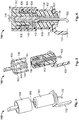
- FIG. 1 shows in the form of a schematic perspective view a contact protection element 116, which finds use in a high-voltage (HV) round plug (e.g. with a diameter of 12 mm).
- HV high-voltage
- Other plug-in connector geometries can of course likewise be designed with temperature detection according to the principles of the present invention.
- the contact protection element 116 has an electrically insulating main body 118 with an elongated, in the assembled state columnar shape.
- the main body 118 can be fabricated from a synthetic material.
- a temperature sensor 112 is embedded in the main body 118 of the contact protection element 116.
- the temperature sensor 112 can exhibit for example an NTC thermistor, a thermoelement, a resistance temperature sensor (e.g. Pt), or any other suitable temperature sensor.
- NTC denotes 'negative temperature coefficient.
- An NTC thermistor is a temperature sensor that uses the resistance properties of ceramic-metal composite materials for temperature measurement. NTC sensors offer many advantages for temperature measurement, e.g. small size, durable stability, high accuracy, and precision.
- thermoelement sensor consists of two unequal metals, joined to each other at one end. The temperature is measured at this branching. The two metals generate a small voltage, which can be measured and evaluated by a control system. The unequal metals are insulated individually, and with the help of a jacket a tight bifilar configuration is maintained. Thermoelement sensors have the advantage of a wide operating temperature range, largely constant sensitivity over their entire range, and availability in suitable miniaturized sizes.
- Resistance sensors known as RTDs (resistance temperature detectors) are sensors that are used for temperature measurement, in that the resistance varies proportionally to the temperature. RTD temperature sensors function even at locations with a harsh or hazardous environment with various official permits.
- the temperature sensor 112 has a sensitive region 120 that performs the actual temperature detection, and an electrical connecting line 122 which connects the temperature sensor 112 with the necessary power supply and measured signal acquisition (not shown in the figures).
- the connecting line 122 is routed through the main body 118 and emerges from the main body 118 at a base region 124. Thereby the temperature sensor 112 and the connecting line 122 are protected optimally against mechanical stressing.
- the contact protection element 116 has at the base region 124 a radially surrounding latching ledge 126, which engages with an associated latching groove 128 for fastening the contact protection element 116 in a plug-in connector element.
- a flange 130 serves in the assembled state for the sealing and mechanical support of the contact protection element 116.
- such a contact protection element 116 fitted with a temperature sensor 112 can be fabricated as a separate part e.g. through overmolding of the temperature sensor 112 and be held ready for the final assembly.
- the mounting of a temperature sensor in a plug-in connector is significantly simplified.
- Fig. 2 shows in perspective view an HV plug-in connector element 102 that is mounted on a current rail 132.
- the contact protection element 116 is so arranged inside an electrically conductive socket contact 134 that access to the electrically conductive parts from outside is impossible for objects that have a larger diameter than a defined test probe.
- the plug-in connector element 102 comprises an electrically insulating housing 136, which covers the socket contact 134 radially all around and on the front side in the insertion region.
- the socket contact 134 comprises an electrically conductive contact main body 138, which establishes the electrical junction to the current rail 132.
- the socket contact 134 For electrical contacting of a mating plug-in connector (see Figures 5 and 6 ), the socket contact 134 comprises a spring contact 140.
- the spring contact 140 comprises a large number of bilaterally fastened, radially inward curved flexible tongues 142, which exert a contact pressure on the contact element of the mating plug-in connector.
- the inward curved region of the flexible tongues 142 forms in the plugged-in state of the plug-in connector the actual electrical contact region 144, in which an undesirable heat buildup first occurs.
- the temperature sensor 112 is so arranged that its sensitive region 120 is located in immediate vicinity to the contact region 144.
- Figures 4 to 6 elucidate the plugging together of the plug-in connector element 102 with a mating plug-in connector element 104 to form a plugged-in state of the plug-in connector 100.
- the mating plug-in connector element 104 comprises a hollow cylindrical electrically conductive mating contact element 146, which when plugging together in the 148 direction grips the contact protection element 116 around and at the same time contacts it electrically from the outside through the spring contact 140.
- the mating plug-in connector 104 has an electrically insulating second housing 152 and an electrically insulating contact protection covering 154.
- the contact protection covering 154 is so formed that between the second housing and the contact protection covering, access to the electrically conductive mating contact element 146 is prevented for objects with a diameter above a defined value.
- the temperature sensor 112 at least in the sensitive region 120 projects slightly from the otherwise smooth outer surface of the contact protection element 116, the temperature sensor is pressed in the plugged-in state on the inner surface of the electrically conductive mating contact element 146.
- the temperature sensor 112 can respond especially rapidly and reliably to overheating in the critical region 150 marked by a dashed line.
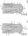
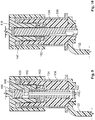
- Figures 7 to 10 illustrate how the otherwise unmodified plug-in connector 100 can be modified in its temperature detection functionality by using different variants of the contact protection element 116.
- Fig. 7 shows again for comparison the arrangement elucidated by reference to Figures 1 to 6 .
- the temperature sensor can also be arranged closer at the base region 124 of the contact protection element 116, in order to be able to monitor the temperature in the vicinity of the current rail.
- the temperature sensor is routed centrally through the contact protection element 116, in order to make possible in this way on the one hand symmetrical temperature detection and on the other protect the temperature sensor mechanically.
- each of the shown contact protection elements 116 preferably the one shown in Fig. 8 , can also be used simply without temperature sensor 112. This variant is shown in Fig. 10 .
- Fig. 11 illustrates again in a perspective view the invention's plug-in connector 100 in the plugged-in state.
- Fig. 12 the contact protection functionality of the plug-in connector element 102 is illustrated. As shown, a test probe 114 cannot penetrate into the free space between the contact protection element 116 and the housing 136 and touch the conductive parts, i.e. the socket contact 134.
- the interaction of the second housing 152 with the contact protection covering 154 prevents the test probe 114 (and for this reason all objects that have a larger diameter than the test probe) touching the electrically conductive mating contact element 146.
- the contact parts e.g. with a 12 mm round contact with the finger protection to situate the temperature sensor installation-space-neutrally and flexibly even in the immediate vicinity of the hotspot.
- the sensor is arranged in the contact protection element at the optimal position as regards contact layout.
- the necessary contact pressure of the sensor on the measurement surface is generated, depending on the mounting position, either by the plugging-in process or when assembling the contact protection.
- the connecting line of the sensor can also be reliably installed and routed away in the contact protection element.
Landscapes
- Engineering & Computer Science (AREA)
- Microelectronics & Electronic Packaging (AREA)
- Details Of Connecting Devices For Male And Female Coupling (AREA)
- Connector Housings Or Holding Contact Members (AREA)
Abstract
Description
- The present invention refers to a plug-in connector element and an associated plug-in connector for high-voltage (HV) applications.
- In electromobility, HV plug-in connectors with large conducting cross-sections are needed for propulsion and for charging the HV battery. In order to shorten the charging times, temperature sensors are used in the HV system. In HV plug-in connectors too, temperature sensors are increasingly needed. The more accurate the temperature measurement in the plug-in connector, the better can the HV system adjust the charging parameters, and thus shorten the charging times. In conventional HV plug-in connectors it is difficult to position the temperature sensor in the vicinity of the contact point (in the following also referred to as 'hotspot'). Often there only remains the option of installing the temperature-measurement sensor in the crimping region or at the current rail (remote from the hotspot).
-
Figures 14 to 16 illustrate a known HV plug-in connector arrangement.Figure 14 shows a schematic sectional view of a plug-inconnector 200 in the plugged-in state. The plug-inconnector 200 comprises a plug-inconnector element 202 and a mating plug-inconnector element 204. As shown, the plug-inconnector element 202 is a socket element with an electrically conductive spring-loadedcontact element 210 and the mating plug-inconnector element 204 is a plug-in element with an electricallyconductive blade contact 206. -
Figure 15 shows the plug-inconnector element 202 in a perspective view.Figure 16 shows the mating plug-inconnector element 204 in a perspective view. In addition,Figures 15 and 16 illustrate the functionality of the contact protection in both connectingelements - The electrical contact between the plug-in
connector element 202 and the mating plug-inconnector element 204 takes place incontact region 208, in which the electrically conductive spring-loadedcontact element 210 presses on theblade contact 206. In order to monitor the temperature of thecontact region 208, atemperature sensor contact region 208. In the known arrangement shown, however, due to the spatial conditions, this is possible only in the connecting region of blade contact 206 (temperature sensor 212A) and/or in the crimping region of the socket element (temperature sensor 212B). For this reason, however, the distance to the actual generation zone of a potential temperature increase is too great to be able to react quickly enough to overheating. The consequence is that e.g. batteries have to be charged with lower charging currents over longer times. - There exists, therefore a need for a plug-in connector element that overcomes the drawbacks of the known solutions, such that the enclosed plug-in connections are safe and reliable in operation, but nevertheless can be fabricated cost-effectively.
- This object is solved by the subject matter of the independent patent claims. Advantageous embodiments of the present invention are the subject matter of the dependent patent claims.
- The present invention is based on the idea of embedding at least one temperature sensor in an HV plug-in connector not in a housing element but in a contact protection element or arranging it at the surface of the contact protection element. In this way the temperature sensor can be arranged directly in the electrical contact zone between the plug-in connector element and the mating plug-in connector element and be connected thermally over the shortest possible distance with the region in which potential overheating arises.
- In particular, a plug-in connector element for detachable electrical contacting of a mating plug-in connector element comprises at least one electrically conductive contact element, one housing, and one contact protection element, which is so disposed that between the housing and the contact protection element, access to the electrically conductive contact element is prevented for objects with a diameter above a defined value. At least one temperature sensor, which at least in part is accommodated within the contact protection element, can be operated in order to measure a temperature of the electrically conductive contact element.
- This arrangement has the advantage that the temperature sensor can be situated installation-space-neutrally and flexibly even in the immediate vicinity of the hotspot. The sensor is arranged in the contact protection element at the optimal position as regards contact layout. The necessary contact pressure of the sensor on the measurement surface is produced, depending on the mounting position, either by the plugging-in process or when assembling the contact protection. The connecting line of the sensor too, can be reliably installed and routed away in the contact protection element. With this solution, temperature measurement in the HV plug-in connector becomes more accurate and more flexible.
- At this point let it be noted that of course not only one single temperature sensor but also a large number of temperature sensors can be arranged in and/or at the contact protection element. Furthermore, temperature sensors with more than only one sensitive region can also be deployed.
- In order to be able to monitor the temperature in real time as far as possible, the at least one temperature sensor is so arranged according to an advantageous embodiment that it measures the temperature of the electrically conductive contact element in a contact region in which the electrically conductive contact element is electrically contactable through an electrically conductive mating contact element of the mating plug-in connector element.
- According to an advantageous aspect, the housing has an essentially cylindrical inner surface at which the electrically conductive contact element is disposed, wherein the electrically conductive contact element grips the contact protection element around at least in part. In this way an especially compact construction can be realized.
- Here the contact protection element can have a columnar structure and the temperature sensor is arranged at an external wall of the contact protection element. Then the temperature sensor comes into especially tight heat-conducting contact with the contact region, in which the electrically conductive contact element is electrically contactable through an electrically conductive mating contact element of the mating plug-in connector element, and the achievable response times to a temperature increase are especially short.
- Alternatively or additionally, it can also be provided that the contact protection element has a columnar structure and the temperature sensor is arranged on the inside of the contact protection element. Here the temperature sensor is especially well protected against mechanical stressing during the plugging-in process.
- According to a further advantageous embodiment of the present invention, the electrically conductive contact element comprises a cylindrical main body and a spring element (also referred to as a spring contact) for spring-loaded contacting of the electrically conductive mating contact element. Thus the necessary contact pressure between the electrical contact elements to one another and to the temperature sensor can be produced in a simple way when connecting together the plug-in connector with the mating plug-in connector.
- In particular, the spring element can have an essentially ring-like shape and have a large number of bilaterally fastened flexible tongues, which at their center are bent radially inward in order to contact the electrically conductive mating contact element. Thereby a uniform and firm contact pressure is ensured which guarantees reliable electrical and mechanical contact even in the presence of vibrations and wide temperature ranges.
- In order to protect the connecting line especially, it can be provided that the electrical connecting line of the at least one temperature sensor is routed through the contact protection element.
- According to an advantageous further development of the present invention, the contact protection element is implemented as an electrically insulating, electrically insulating synthetic part pressed into the electrically conductive contact element. Thereby the temperature sensor can be for example directly so overmolded, that its housing simultaneously forms the contact protection element. This reduces the manufacturing costs and ensures a compact construction.
- The present invention further concerns a plug-in connector with a plug-in connector element according to the present invention and an associated mating plug-in connector element.
- According to an exemplary embodiment, the mating plug-in connector element has an electrically conductive mating contact element with a cylindrical contact region, where in the plugged-in state of the plug-in connector the contact region of the electrically conductive mating contact element grips the contact protection element around. Such a concentric construction has the advantage of an especially compact construction and symmetrical force distribution when plugging in the connector elements.
- In order to achieve especially good heat transfer and thus a short response time, it can be provided that the at least one temperature sensor is pressed onto the electrically conductive mating contact element in the plugged-in state of the plug-in connector.
- So that both connector elements satisfy the requirements of contact safety for HV components, it can be provided that the mating plug-in connector element further has a second housing and a contact protection covering, where the contact protection covering is so disposed that between the second housing and the contact protection covering, access to the electrically conductive mating contact element is prevented for objects with a diameter above a defined value. For example, the contact protection covering is formed by an essentially ring-shaped electrically insulating synthetic part, which is arranged on a front-side end region of the electrically conductive mating contact element. Such a synthetic part can be manufactured cost-effectively and is either clipped or injection-molded onto a metallic contact element.
- The advantageous properties of the invention's plug-in connector come into effect especially when the plug-in connector is implemented as a high-voltage plug-in connector for an electric vehicle.
- For better understanding of the present invention, it is elucidated in more detail by means of the embodiments shown in the following figures. Here the same parts are given the same reference numerals and the same component designations. Furthermore also, some features or feature combinations from the various shown and described embodiments can represent separate independent, innovative, or inventive solutions. The figures show:
- Fig. 1
- A schematic perspective view of a contact protection element according to an aspect of the present invention;
- Fig. 2
- A schematic perspective view of a plug-in connector element with the contact protection element from
Fig. 1 ; - Fig. 3
- A schematic sectional view of the plug-in connector element from
Fig. 2 ; - Fig. 4
- A schematic perspective view of a plug-in connector with the plug-in connector element from
Fig. 2 before plugging in; - Fig. 5
- A schematic sectional view of the plug-in connector from
Fig. 4 ; - Fig. 6
- A detail from
Fig. 5 ; - Fig. 7-10
- Sectional views of various examples of plug-in connectors with different contact protection elements;
- Fig. 11
- A schematic perspective view of a plug-in connector with the plug-in connector element from
Fig. 2 after plugging in; - Fig. 12
- A schematic perspective view of the plug-in connector from
Fig. 2 for illustrating the contact protection functionality; - Fig. 13
- A schematic perspective view of the mating plug-in connector from
Fig. 4 for illustrating the contact protection functionality; - Fig. 14
- A schematic sectional view of a known HV plug-in connector;
- Fig. 15
- A schematic perspective view of the plug-in connector element from
Fig. 14 ; - Fig. 16
- A schematic perspective view of the mating plug-in connector element from
Fig. 14 . - In the following, the present invention is elucidated in more detail by reference to the figures, and in particular first by reference to the perspective view of
Figure 1 . Note that in all figures the size relationships and in particular the layer thickness relationships are not necessarily reproduced to scale. -
Figure 1 shows in the form of a schematic perspective view acontact protection element 116, which finds use in a high-voltage (HV) round plug (e.g. with a diameter of 12 mm). Other plug-in connector geometries can of course likewise be designed with temperature detection according to the principles of the present invention. - According to an aspect of the present invention, the
contact protection element 116 has an electrically insulatingmain body 118 with an elongated, in the assembled state columnar shape. For example, themain body 118 can be fabricated from a synthetic material. - According to the invention, a
temperature sensor 112 is embedded in themain body 118 of thecontact protection element 116. Thetemperature sensor 112 can exhibit for example an NTC thermistor, a thermoelement, a resistance temperature sensor (e.g. Pt), or any other suitable temperature sensor. - NTC denotes 'negative temperature coefficient.' An NTC thermistor is a temperature sensor that uses the resistance properties of ceramic-metal composite materials for temperature measurement. NTC sensors offer many advantages for temperature measurement, e.g. small size, durable stability, high accuracy, and precision.
- A thermoelement sensor consists of two unequal metals, joined to each other at one end. The temperature is measured at this branching. The two metals generate a small voltage, which can be measured and evaluated by a control system. The unequal metals are insulated individually, and with the help of a jacket a tight bifilar configuration is maintained. Thermoelement sensors have the advantage of a wide operating temperature range, largely constant sensitivity over their entire range, and availability in suitable miniaturized sizes.
- Resistance sensors, known as RTDs (resistance temperature detectors), are sensors that are used for temperature measurement, in that the resistance varies proportionally to the temperature. RTD temperature sensors function even at locations with a harsh or hazardous environment with various official permits.
- The
temperature sensor 112 has asensitive region 120 that performs the actual temperature detection, and an electrical connectingline 122 which connects thetemperature sensor 112 with the necessary power supply and measured signal acquisition (not shown in the figures). - According to an aspect of the present invention, the connecting
line 122 is routed through themain body 118 and emerges from themain body 118 at abase region 124. Thereby thetemperature sensor 112 and the connectingline 122 are protected optimally against mechanical stressing. - As becomes evident from the following
Figure 3 , thecontact protection element 116 has at the base region 124 a radially surrounding latchingledge 126, which engages with an associated latchinggroove 128 for fastening thecontact protection element 116 in a plug-in connector element. Aflange 130 serves in the assembled state for the sealing and mechanical support of thecontact protection element 116. - Advantageously, such a
contact protection element 116 fitted with atemperature sensor 112 can be fabricated as a separate part e.g. through overmolding of thetemperature sensor 112 and be held ready for the final assembly. Thereby, the mounting of a temperature sensor in a plug-in connector is significantly simplified. -
Fig. 2 shows in perspective view an HV plug-inconnector element 102 that is mounted on acurrent rail 132. As is apparent from the synopsis with the sectional view ofFig. 3 , thecontact protection element 116 is so arranged inside an electricallyconductive socket contact 134 that access to the electrically conductive parts from outside is impossible for objects that have a larger diameter than a defined test probe. The plug-inconnector element 102 comprises an electrically insulatinghousing 136, which covers thesocket contact 134 radially all around and on the front side in the insertion region. - The
socket contact 134 comprises an electrically conductive contactmain body 138, which establishes the electrical junction to thecurrent rail 132. For electrical contacting of a mating plug-in connector (seeFigures 5 and 6 ), thesocket contact 134 comprises aspring contact 140. Thespring contact 140 comprises a large number of bilaterally fastened, radially inward curvedflexible tongues 142, which exert a contact pressure on the contact element of the mating plug-in connector. The inward curved region of theflexible tongues 142 forms in the plugged-in state of the plug-in connector the actualelectrical contact region 144, in which an undesirable heat buildup first occurs. - In order to detect overheating rapidly, according to a first advantageous aspect of the present invention the
temperature sensor 112 is so arranged that itssensitive region 120 is located in immediate vicinity to thecontact region 144. -
Figures 4 to 6 elucidate the plugging together of the plug-inconnector element 102 with a mating plug-inconnector element 104 to form a plugged-in state of the plug-inconnector 100. - According to the shown embodiment, the mating plug-in
connector element 104 comprises a hollow cylindrical electrically conductivemating contact element 146, which when plugging together in the 148 direction grips thecontact protection element 116 around and at the same time contacts it electrically from the outside through thespring contact 140. - For electric insulation, the mating plug-in
connector 104 has an electrically insulatingsecond housing 152 and an electrically insulating contact protection covering 154. The contact protection covering 154 is so formed that between the second housing and the contact protection covering, access to the electrically conductivemating contact element 146 is prevented for objects with a diameter above a defined value. - If one provides that the
temperature sensor 112 at least in thesensitive region 120 projects slightly from the otherwise smooth outer surface of thecontact protection element 116, the temperature sensor is pressed in the plugged-in state on the inner surface of the electrically conductivemating contact element 146. Thus an especially tight thermal contact is ensured and thetemperature sensor 112 can respond especially rapidly and reliably to overheating in thecritical region 150 marked by a dashed line. -
Figures 7 to 10 illustrate how the otherwise unmodified plug-inconnector 100 can be modified in its temperature detection functionality by using different variants of thecontact protection element 116. -
Fig. 7 shows again for comparison the arrangement elucidated by reference toFigures 1 to 6 . - As shown in
Fig. 8 , the temperature sensor can also be arranged closer at thebase region 124 of thecontact protection element 116, in order to be able to monitor the temperature in the vicinity of the current rail. - Furthermore, it can also be provided that the temperature sensor is routed centrally through the
contact protection element 116, in order to make possible in this way on the one hand symmetrical temperature detection and on the other protect the temperature sensor mechanically. - Finally, each of the shown
contact protection elements 116, preferably the one shown inFig. 8 , can also be used simply withouttemperature sensor 112. This variant is shown inFig. 10 . - All the variations shown in
Figures 7 to 9 can also be combined with each other, by using more than only onetemperature sensor 112 or a sensor with more than onesensitive region 120. -
Fig. 11 illustrates again in a perspective view the invention's plug-inconnector 100 in the plugged-in state. - In
Fig. 12 the contact protection functionality of the plug-inconnector element 102 is illustrated. As shown, atest probe 114 cannot penetrate into the free space between thecontact protection element 116 and thehousing 136 and touch the conductive parts, i.e. thesocket contact 134. - Likewise, as shown in
Fig. 13 , the interaction of thesecond housing 152 with the contact protection covering 154 prevents the test probe 114 (and for this reason all objects that have a larger diameter than the test probe) touching the electrically conductivemating contact element 146. - In summary, according to an exemplary aspect of the present invention, it is made possible through a new arrangement of the contact parts e.g. with a 12 mm round contact with the finger protection to situate the temperature sensor installation-space-neutrally and flexibly even in the immediate vicinity of the hotspot. The sensor is arranged in the contact protection element at the optimal position as regards contact layout. The necessary contact pressure of the sensor on the measurement surface is generated, depending on the mounting position, either by the plugging-in process or when assembling the contact protection. The connecting line of the sensor can also be reliably installed and routed away in the contact protection element. With this solution, the temperature measurement in the HV plug-in connector becomes more accurate and more flexible.
- It should further be noted that although in the above description as an example always a round contact is described, nevertheless other contact cross-sections and also multiple contacts can of course likewise be designed according to the principles of the present invention.
List of reference numerals: Reference no. Description 100, 200 Plug-in connector 102, 202 Plug-in connector element 104, 204 Mating plug-in connector element 206 Blade contact 108, 208 Contact region 110, 210 Spring-loaded contact element 112, 212A, 212B Temperature sensor 114, 214 Test probe 116 Contact protection element 118 Main body of the contact protection element 120 Sensitive region 122 Connecting line 124 Base region 126 Latching ledge 128 Latch in (groove 130 Flange 132 Current rail 134 Socket contact; contact element 136 (First) housing 138 Contact main body 140 Spring contact 142 Flexible tongue 144 Contact region 146 Mating contact element 148 Plug-in direction 150 Critical region 152 Mating plug-in connector housing; second housing 154 Contact protection covering
Claims (15)
- Plug-in connector element for detachable electrical contacting of a mating plug-in connector element (104), wherein the plug-in connector element (102) comprises:at least one electrically conductive contact element (134),a housing (136),a contact protection element (116) which is so disposed that between the housing (136) and the contact protection element (116) access to the electrically conductive contact element (134) is prevented for objects with a diameter above a defined value, andat least one temperature sensor (112), which at least in part is accommodated within the contact protection element (116) and can be operated to measure a temperature of the electrically conductive contact element (134).
- Plug-in connector element according to Claim 1, wherein the at least one temperature sensor (112) is so arranged that it detects the temperature of the electrically conductive contact element (134) in a contact region (144) in which the electrically conductive contact element (134) is electrically contactable through an electrically conductive mating contact element (146) of the mating plug-in connector element (104).
- Plug-in connector element according to Claim 1 or 2, wherein the housing (136) has an essentially cylindrical inner surface at which the electrically conductive contact element (134) is disposed, and wherein the electrically conductive contact element (134) encompasses the contact protection element (116) at least in part.
- Plug-in connector element according to one of the preceding Claims, wherein the contact protection element (116) has a columnar structure and the temperature sensor (112) is arranged at an external wall of the contact protection element (116).
- Plug-in connector element according to one of the preceding Claims, wherein the contact protection element (116) has a columnar structure and the temperature sensor (112) is arranged on the inside of the contact protection element (116).
- Plug-in connector element according to one of the preceding Claims, wherein the electrically conductive contact element (134) comprises a cylindrical main body (138) and a spring contact (140) for spring-loaded contacting of the electrically conductive mating contact element (146).
- Plug-in connector element according to Claim 6, wherein the spring contact (140) has an essentially ring-like shape and comprises a large number of bilaterally fastened flexible tongues (142), which at their center are bent radially inward in order to contact the electrically conductive mating contact element (146).
- Plug-in connector element according to one of the preceding Claims, wherein an electrical connecting line (122) of the at least one temperature sensor (112) is routed through the contact protection element (116).
- Plug-in connector element according to one of the preceding Claims, wherein the contact protection element (116) is implemented as an electrically insulating, electrically insulating synthetic part pressed into the electrically conductive contact element (134).
- Plug-in connector comprising a plug-in connector element (102) according to one of the preceding Claims and an associated mating plug-in connector element (104).
- Plug-in connector according to Claim 10, wherein the mating plug-in connector element (104) has an electrically conductive mating contact element (146) with a cylindrical contact region and wherein in the plugged-in state of the plug-in connector (100) the contact region of the electrically conductive mating contact element (146) encompasses the contact protection element (116).
- Plug-in connector according to Claim 10 or 11, wherein the at least one temperature sensor (112) is pressed onto the electrically conductive mating contact element (146) in the plugged-in state of the plug-in connector (100).
- Plug-in connector according to one of the Claims 10 to 12, wherein the mating plug-in connector element (104) further comprises a second housing (152) and a contact protection covering (154), and wherein the contact protection covering (154) is so disposed that between the second housing (152) and the contact protection covering (154) access to the electrically conductive mating contact element (146) is prevented for objects with a diameter above a defined value.
- Plug-in connector according to Claim 11 and 13, wherein the contact protection covering (154) is formed by an essentially ring-shaped electrically insulating synthetic part, which is arranged on the front-side end region of the electrically conductive mating contact element (146).
- Plug-in connector according to one of the Claims 10 to 14, wherein the plug-in connector (100) is implemented as a high-voltage plug-in connector for an electric vehicle.
Applications Claiming Priority (1)
| Application Number | Priority Date | Filing Date | Title |
|---|---|---|---|
| DE102020201240.7A DE102020201240A1 (en) | 2020-01-31 | 2020-01-31 | Connector element and connector for high-voltage applications |
Publications (2)
| Publication Number | Publication Date |
|---|---|
| EP3859908A1 true EP3859908A1 (en) | 2021-08-04 |
| EP3859908B1 EP3859908B1 (en) | 2025-04-02 |
Family
ID=74187154
Family Applications (1)
| Application Number | Title | Priority Date | Filing Date |
|---|---|---|---|
| EP21152086.1A Active EP3859908B1 (en) | 2020-01-31 | 2021-01-18 | Plug-in connector element and plug-in connector for high-voltage applications |
Country Status (6)
| Country | Link |
|---|---|
| US (1) | US11462863B2 (en) |
| EP (1) | EP3859908B1 (en) |
| JP (1) | JP7683229B2 (en) |
| KR (1) | KR102848323B1 (en) |
| CN (1) | CN113206402B (en) |
| DE (1) | DE102020201240A1 (en) |
Cited By (1)
| Publication number | Priority date | Publication date | Assignee | Title |
|---|---|---|---|---|
| TWI859526B (en) * | 2021-09-03 | 2024-10-21 | 凡甲科技股份有限公司 | Electrical connector |
Families Citing this family (5)
| Publication number | Priority date | Publication date | Assignee | Title |
|---|---|---|---|---|
| DE102017222541A1 (en) * | 2017-12-13 | 2019-06-13 | Bayerische Motoren Werke Aktiengesellschaft | High-voltage connector part for a high-voltage connector of a motor vehicle, high-voltage vehicle electrical system and motor vehicle |
| CN218569289U (en) * | 2022-09-21 | 2023-03-03 | 长春捷翼汽车零部件有限公司 | Electrical connector |
| DE102022131544A1 (en) | 2022-11-29 | 2024-05-29 | Te Connectivity Solutions Gmbh | Connector with an output unit for connection to an evaluation unit for determining a temperature of a contact point and method for determining a temperature of a contact point of a connector |
| CN220138880U (en) * | 2023-04-26 | 2023-12-05 | 常州捷翼汽车零部件有限公司 | An electric energy transmission mechanism |
| DE102023124169B4 (en) * | 2023-09-07 | 2025-03-27 | Amphenol Tuchel Industrial GmbH | Plug contact and plug contact plug with two plug contacts |
Citations (2)
| Publication number | Priority date | Publication date | Assignee | Title |
|---|---|---|---|---|
| EP2720324A1 (en) * | 2012-10-10 | 2014-04-16 | Dai-Ichi Seiko Co., Ltd. | Electric connector |
| DE102017222808A1 (en) * | 2017-12-14 | 2019-06-19 | Phoenix Contact E-Mobility Gmbh | Load contact module and charging plug |
Family Cites Families (20)
| Publication number | Priority date | Publication date | Assignee | Title |
|---|---|---|---|---|
| WO2002013331A1 (en) | 2000-08-04 | 2002-02-14 | Fladung, Manfred | Electrical plug-in connector |
| US9007674B2 (en) | 2011-09-30 | 2015-04-14 | View, Inc. | Defect-mitigation layers in electrochromic devices |
| DE102011004347A1 (en) * | 2011-02-17 | 2012-08-23 | Tyco Electronics Amp Gmbh | Electrical connector and plug-in system |
| JP6130244B2 (en) | 2013-06-27 | 2017-05-17 | 矢崎総業株式会社 | Terminal and charging connector |
| DE102015213674A1 (en) | 2014-07-21 | 2016-01-21 | Hirschmann Automotive Gmbh | Plug connection with a socket contact and a pin contact |
| DE102014111185A1 (en) * | 2014-08-06 | 2016-02-11 | Phoenix Contact E-Mobility Gmbh | Connector part with a temperature sensor device |
| KR20170087121A (en) * | 2016-01-19 | 2017-07-28 | 통일전자공업(주) | Power plug for electric vehicle having a temparature sensor and an american type terminal and menufacturing method therof |
| WO2017197134A1 (en) * | 2016-05-11 | 2017-11-16 | Hubbell Incorporated | Power connector with integrated power monitoring |
| JP6571700B2 (en) * | 2017-02-01 | 2019-09-04 | 矢崎総業株式会社 | connector |
| CN107887725B (en) * | 2017-07-03 | 2022-08-30 | 深圳市沃尔新能源电气科技股份有限公司 | Connector plug terminal and charging gun connector |
| DE102017212493A1 (en) | 2017-07-20 | 2018-08-02 | Siemens Aktiengesellschaft | Electrical connector, assembly with an electrical connector, use of an electrical connector and method of operating an electrical connector |
| DE102017222541A1 (en) * | 2017-12-13 | 2019-06-13 | Bayerische Motoren Werke Aktiengesellschaft | High-voltage connector part for a high-voltage connector of a motor vehicle, high-voltage vehicle electrical system and motor vehicle |
| JP6951663B2 (en) * | 2017-12-26 | 2021-10-20 | 住友電装株式会社 | connector |
| JP7006483B2 (en) | 2018-04-24 | 2022-02-10 | トヨタ自動車株式会社 | connector |
| DE202018002686U1 (en) * | 2018-06-06 | 2018-07-12 | Heraeus Sensor Technology Gmbh | Connector for disconnecting and connecting at least one electrical contact for charging a battery unit of a motor vehicle |
| US10833458B2 (en) * | 2018-08-21 | 2020-11-10 | Te Connectivity Corporation | Temperature sensor assembly for an electrical connector |
| BE1026857B1 (en) * | 2018-12-10 | 2020-07-13 | Phoenix Contact E Mobility Gmbh | Connector part with a circuit board |
| CN209626594U (en) * | 2019-04-19 | 2019-11-12 | 台达电子企业管理(上海)有限公司 | Fast spigot submodule and power-supply system |
| US11427099B2 (en) * | 2019-09-16 | 2022-08-30 | TE Connectivity Services Gmbh | Temperature sensor for terminal of charging inlet assembly |
| JP7068360B2 (en) * | 2020-02-04 | 2022-05-16 | 矢崎総業株式会社 | connector |
-
2020
- 2020-01-31 DE DE102020201240.7A patent/DE102020201240A1/en not_active Ceased
-
2021
- 2021-01-18 EP EP21152086.1A patent/EP3859908B1/en active Active
- 2021-01-27 JP JP2021010776A patent/JP7683229B2/en active Active
- 2021-01-28 KR KR1020210012453A patent/KR102848323B1/en active Active
- 2021-01-28 CN CN202110116274.7A patent/CN113206402B/en active Active
- 2021-01-28 US US17/161,037 patent/US11462863B2/en active Active
Patent Citations (2)
| Publication number | Priority date | Publication date | Assignee | Title |
|---|---|---|---|---|
| EP2720324A1 (en) * | 2012-10-10 | 2014-04-16 | Dai-Ichi Seiko Co., Ltd. | Electric connector |
| DE102017222808A1 (en) * | 2017-12-14 | 2019-06-19 | Phoenix Contact E-Mobility Gmbh | Load contact module and charging plug |
Cited By (1)
| Publication number | Priority date | Publication date | Assignee | Title |
|---|---|---|---|---|
| TWI859526B (en) * | 2021-09-03 | 2024-10-21 | 凡甲科技股份有限公司 | Electrical connector |
Also Published As
| Publication number | Publication date |
|---|---|
| JP2021125466A (en) | 2021-08-30 |
| JP7683229B2 (en) | 2025-05-27 |
| CN113206402A (en) | 2021-08-03 |
| CN113206402B (en) | 2026-08-07 |
| US20210242636A1 (en) | 2021-08-05 |
| KR20210098370A (en) | 2021-08-10 |
| DE102020201240A1 (en) | 2021-08-05 |
| US11462863B2 (en) | 2022-10-04 |
| KR102848323B1 (en) | 2025-08-20 |
| EP3859908B1 (en) | 2025-04-02 |
Similar Documents
| Publication | Publication Date | Title |
|---|---|---|
| EP3859908B1 (en) | Plug-in connector element and plug-in connector for high-voltage applications | |
| KR102231028B1 (en) | Electrical apparatus comprising a temperature sensor housed in a support element | |
| CN113853716B (en) | Plug-in connector component comprising a sensor device arranged on a contact strip of a contact element | |
| AU2019408452B2 (en) | Sealed electric plug | |
| EP3560750A1 (en) | Charging connector | |
| US10439336B2 (en) | Plug connector part having a temperature sensor device | |
| US11385106B2 (en) | Assembly for detecting temperature and contact assembly having such an assembly | |
| CN113285273B (en) | Connector with a plurality of connectors | |
| US20240208342A1 (en) | Plug connector part for a charging system for charging an electric vehicle | |
| US11984275B2 (en) | Electrical mains plug | |
| JP5807811B2 (en) | Temperature sensor device | |
| CN113594799A (en) | electrical connector | |
| US20230396027A1 (en) | Temperature detection device for a plug connector part | |
| CN110718816A (en) | Plug-in connector | |
| US20250214459A1 (en) | Plug connector part | |
| JP7182666B2 (en) | High-current contact means and connection devices for transmitting electrical energy in motor vehicles | |
| US20250055236A1 (en) | Plug connector part for a charging system for charging an electric vehicle | |
| EP3818599B1 (en) | Adapter device with heat protection switch | |
| US20240006824A1 (en) | Device For Detecting The Temperature Of An Electric Coupling Element, And Method | |
| CN113267265A (en) | Gas turbine gas temperature measurement system, gas turbine, and temperature measurement method | |
| CN210603640U (en) | Temperature sensor | |
| CN120813820A (en) | Sensor device |
Legal Events
| Date | Code | Title | Description |
|---|---|---|---|
| PUAI | Public reference made under article 153(3) epc to a published international application that has entered the european phase |
Free format text: ORIGINAL CODE: 0009012 |
|
| STAA | Information on the status of an ep patent application or granted ep patent |
Free format text: STATUS: THE APPLICATION HAS BEEN PUBLISHED |
|
| AK | Designated contracting states |
Kind code of ref document: A1 Designated state(s): AL AT BE BG CH CY CZ DE DK EE ES FI FR GB GR HR HU IE IS IT LI LT LU LV MC MK MT NL NO PL PT RO RS SE SI SK SM TR |
|
| STAA | Information on the status of an ep patent application or granted ep patent |
Free format text: STATUS: REQUEST FOR EXAMINATION WAS MADE |
|
| 17P | Request for examination filed |
Effective date: 20220202 |
|
| RBV | Designated contracting states (corrected) |
Designated state(s): AL AT BE BG CH CY CZ DE DK EE ES FI FR GB GR HR HU IE IS IT LI LT LU LV MC MK MT NL NO PL PT RO RS SE SI SK SM TR |
|
| STAA | Information on the status of an ep patent application or granted ep patent |
Free format text: STATUS: EXAMINATION IS IN PROGRESS |
|
| 17Q | First examination report despatched |
Effective date: 20230214 |
|
| GRAP | Despatch of communication of intention to grant a patent |
Free format text: ORIGINAL CODE: EPIDOSNIGR1 |
|
| STAA | Information on the status of an ep patent application or granted ep patent |
Free format text: STATUS: GRANT OF PATENT IS INTENDED |
|
| RIC1 | Information provided on ipc code assigned before grant |
Ipc: H01R 13/53 20060101ALN20241024BHEP Ipc: H01R 13/44 20060101ALI20241024BHEP Ipc: H01R 13/66 20060101ALI20241024BHEP Ipc: H01R 24/38 20110101AFI20241024BHEP |
|
| INTG | Intention to grant announced |
Effective date: 20241105 |
|
| GRAS | Grant fee paid |
Free format text: ORIGINAL CODE: EPIDOSNIGR3 |
|
| GRAA | (expected) grant |
Free format text: ORIGINAL CODE: 0009210 |
|
| STAA | Information on the status of an ep patent application or granted ep patent |
Free format text: STATUS: THE PATENT HAS BEEN GRANTED |
|
| AK | Designated contracting states |
Kind code of ref document: B1 Designated state(s): AL AT BE BG CH CY CZ DE DK EE ES FI FR GB GR HR HU IE IS IT LI LT LU LV MC MK MT NL NO PL PT RO RS SE SI SK SM TR |
|
| REG | Reference to a national code |
Ref country code: GB Ref legal event code: FG4D |
|
| REG | Reference to a national code |
Ref country code: CH Ref legal event code: EP |
|
| REG | Reference to a national code |
Ref country code: IE Ref legal event code: FG4D |
|
| REG | Reference to a national code |
Ref country code: DE Ref legal event code: R096 Ref document number: 602021028351 Country of ref document: DE |
|
| REG | Reference to a national code |
Ref country code: NL Ref legal event code: MP Effective date: 20250402 |
|
| PG25 | Lapsed in a contracting state [announced via postgrant information from national office to epo] |
Ref country code: NL Free format text: LAPSE BECAUSE OF FAILURE TO SUBMIT A TRANSLATION OF THE DESCRIPTION OR TO PAY THE FEE WITHIN THE PRESCRIBED TIME-LIMIT Effective date: 20250402 |
|
| REG | Reference to a national code |
Ref country code: AT Ref legal event code: MK05 Ref document number: 1782269 Country of ref document: AT Kind code of ref document: T Effective date: 20250402 |
|
| PG25 | Lapsed in a contracting state [announced via postgrant information from national office to epo] |
Ref country code: PT Free format text: LAPSE BECAUSE OF FAILURE TO SUBMIT A TRANSLATION OF THE DESCRIPTION OR TO PAY THE FEE WITHIN THE PRESCRIBED TIME-LIMIT Effective date: 20250804 Ref country code: ES Free format text: LAPSE BECAUSE OF FAILURE TO SUBMIT A TRANSLATION OF THE DESCRIPTION OR TO PAY THE FEE WITHIN THE PRESCRIBED TIME-LIMIT Effective date: 20250402 Ref country code: FI Free format text: LAPSE BECAUSE OF FAILURE TO SUBMIT A TRANSLATION OF THE DESCRIPTION OR TO PAY THE FEE WITHIN THE PRESCRIBED TIME-LIMIT Effective date: 20250402 |
|
| REG | Reference to a national code |
Ref country code: LT Ref legal event code: MG9D |
|
| PG25 | Lapsed in a contracting state [announced via postgrant information from national office to epo] |
Ref country code: NO Free format text: LAPSE BECAUSE OF FAILURE TO SUBMIT A TRANSLATION OF THE DESCRIPTION OR TO PAY THE FEE WITHIN THE PRESCRIBED TIME-LIMIT Effective date: 20250702 Ref country code: GR Free format text: LAPSE BECAUSE OF FAILURE TO SUBMIT A TRANSLATION OF THE DESCRIPTION OR TO PAY THE FEE WITHIN THE PRESCRIBED TIME-LIMIT Effective date: 20250703 |
|
| PG25 | Lapsed in a contracting state [announced via postgrant information from national office to epo] |
Ref country code: PL Free format text: LAPSE BECAUSE OF FAILURE TO SUBMIT A TRANSLATION OF THE DESCRIPTION OR TO PAY THE FEE WITHIN THE PRESCRIBED TIME-LIMIT Effective date: 20250402 |
|
| PG25 | Lapsed in a contracting state [announced via postgrant information from national office to epo] |
Ref country code: BG Free format text: LAPSE BECAUSE OF FAILURE TO SUBMIT A TRANSLATION OF THE DESCRIPTION OR TO PAY THE FEE WITHIN THE PRESCRIBED TIME-LIMIT Effective date: 20250402 |
|
| PG25 | Lapsed in a contracting state [announced via postgrant information from national office to epo] |
Ref country code: HR Free format text: LAPSE BECAUSE OF FAILURE TO SUBMIT A TRANSLATION OF THE DESCRIPTION OR TO PAY THE FEE WITHIN THE PRESCRIBED TIME-LIMIT Effective date: 20250402 |
|
| PG25 | Lapsed in a contracting state [announced via postgrant information from national office to epo] |
Ref country code: AT Free format text: LAPSE BECAUSE OF FAILURE TO SUBMIT A TRANSLATION OF THE DESCRIPTION OR TO PAY THE FEE WITHIN THE PRESCRIBED TIME-LIMIT Effective date: 20250402 |
|
| PG25 | Lapsed in a contracting state [announced via postgrant information from national office to epo] |
Ref country code: RS Free format text: LAPSE BECAUSE OF FAILURE TO SUBMIT A TRANSLATION OF THE DESCRIPTION OR TO PAY THE FEE WITHIN THE PRESCRIBED TIME-LIMIT Effective date: 20250702 |
|
| PG25 | Lapsed in a contracting state [announced via postgrant information from national office to epo] |
Ref country code: IS Free format text: LAPSE BECAUSE OF FAILURE TO SUBMIT A TRANSLATION OF THE DESCRIPTION OR TO PAY THE FEE WITHIN THE PRESCRIBED TIME-LIMIT Effective date: 20250802 |
|
| PG25 | Lapsed in a contracting state [announced via postgrant information from national office to epo] |
Ref country code: LV Free format text: LAPSE BECAUSE OF FAILURE TO SUBMIT A TRANSLATION OF THE DESCRIPTION OR TO PAY THE FEE WITHIN THE PRESCRIBED TIME-LIMIT Effective date: 20250402 |
|
| REG | Reference to a national code |
Ref country code: DE Ref legal event code: R097 Ref document number: 602021028351 Country of ref document: DE |
|
| PG25 | Lapsed in a contracting state [announced via postgrant information from national office to epo] |
Ref country code: SM Free format text: LAPSE BECAUSE OF FAILURE TO SUBMIT A TRANSLATION OF THE DESCRIPTION OR TO PAY THE FEE WITHIN THE PRESCRIBED TIME-LIMIT Effective date: 20250402 Ref country code: DK Free format text: LAPSE BECAUSE OF FAILURE TO SUBMIT A TRANSLATION OF THE DESCRIPTION OR TO PAY THE FEE WITHIN THE PRESCRIBED TIME-LIMIT Effective date: 20250402 |
|
| PGFP | Annual fee paid to national office [announced via postgrant information from national office to epo] |
Ref country code: FR Payment date: 20251208 Year of fee payment: 6 |
|
| PG25 | Lapsed in a contracting state [announced via postgrant information from national office to epo] |
Ref country code: CZ Free format text: LAPSE BECAUSE OF FAILURE TO SUBMIT A TRANSLATION OF THE DESCRIPTION OR TO PAY THE FEE WITHIN THE PRESCRIBED TIME-LIMIT Effective date: 20250402 |
|
| PG25 | Lapsed in a contracting state [announced via postgrant information from national office to epo] |
Ref country code: EE Free format text: LAPSE BECAUSE OF FAILURE TO SUBMIT A TRANSLATION OF THE DESCRIPTION OR TO PAY THE FEE WITHIN THE PRESCRIBED TIME-LIMIT Effective date: 20250402 |
|
| PG25 | Lapsed in a contracting state [announced via postgrant information from national office to epo] |
Ref country code: RO Free format text: LAPSE BECAUSE OF FAILURE TO SUBMIT A TRANSLATION OF THE DESCRIPTION OR TO PAY THE FEE WITHIN THE PRESCRIBED TIME-LIMIT Effective date: 20250402 Ref country code: SK Free format text: LAPSE BECAUSE OF FAILURE TO SUBMIT A TRANSLATION OF THE DESCRIPTION OR TO PAY THE FEE WITHIN THE PRESCRIBED TIME-LIMIT Effective date: 20250402 |
|
| PLBE | No opposition filed within time limit |
Free format text: ORIGINAL CODE: 0009261 |
|
| STAA | Information on the status of an ep patent application or granted ep patent |
Free format text: STATUS: NO OPPOSITION FILED WITHIN TIME LIMIT |
|
| REG | Reference to a national code |
Ref country code: CH Ref legal event code: L10 Free format text: ST27 STATUS EVENT CODE: U-0-0-L10-L00 (AS PROVIDED BY THE NATIONAL OFFICE) Effective date: 20260211 |
|
| 26N | No opposition filed |
Effective date: 20260105 |
|
| PGFP | Annual fee paid to national office [announced via postgrant information from national office to epo] |
Ref country code: DE Payment date: 20251203 Year of fee payment: 6 |
|
| PGFP | Annual fee paid to national office [announced via postgrant information from national office to epo] |
Ref country code: IT Payment date: 20251219 Year of fee payment: 6 |
|
| PG25 | Lapsed in a contracting state [announced via postgrant information from national office to epo] |
Ref country code: LT Free format text: LAPSE BECAUSE OF FAILURE TO SUBMIT A TRANSLATION OF THE DESCRIPTION OR TO PAY THE FEE WITHIN THE PRESCRIBED TIME-LIMIT Effective date: 20250402 |
|
| PG25 | Lapsed in a contracting state [announced via postgrant information from national office to epo] |
Ref country code: SE Free format text: LAPSE BECAUSE OF FAILURE TO SUBMIT A TRANSLATION OF THE DESCRIPTION OR TO PAY THE FEE WITHIN THE PRESCRIBED TIME-LIMIT Effective date: 20250402 |