EP3859818A1 - Battery module - Google Patents
Battery module Download PDFInfo
- Publication number
- EP3859818A1 EP3859818A1 EP19887806.8A EP19887806A EP3859818A1 EP 3859818 A1 EP3859818 A1 EP 3859818A1 EP 19887806 A EP19887806 A EP 19887806A EP 3859818 A1 EP3859818 A1 EP 3859818A1
- Authority
- EP
- European Patent Office
- Prior art keywords
- connecting strip
- bulge
- battery module
- via hole
- disposed
- Prior art date
- Legal status (The legal status is an assumption and is not a legal conclusion. Google has not performed a legal analysis and makes no representation as to the accuracy of the status listed.)
- Granted
Links
Images


Classifications
-
- H—ELECTRICITY
- H01—ELECTRIC ELEMENTS
- H01M—PROCESSES OR MEANS, e.g. BATTERIES, FOR THE DIRECT CONVERSION OF CHEMICAL ENERGY INTO ELECTRICAL ENERGY
- H01M10/00—Secondary cells; Manufacture thereof
- H01M10/04—Construction or manufacture in general
- H01M10/0481—Compression means other than compression means for stacks of electrodes and separators
-
- H—ELECTRICITY
- H01—ELECTRIC ELEMENTS
- H01M—PROCESSES OR MEANS, e.g. BATTERIES, FOR THE DIRECT CONVERSION OF CHEMICAL ENERGY INTO ELECTRICAL ENERGY
- H01M50/00—Constructional details or processes of manufacture of the non-active parts of electrochemical cells other than fuel cells, e.g. hybrid cells
- H01M50/20—Mountings; Secondary casings or frames; Racks, modules or packs; Suspension devices; Shock absorbers; Transport or carrying devices; Holders
- H01M50/204—Racks, modules or packs for multiple batteries or multiple cells
- H01M50/207—Racks, modules or packs for multiple batteries or multiple cells characterised by their shape
- H01M50/209—Racks, modules or packs for multiple batteries or multiple cells characterised by their shape adapted for prismatic or rectangular cells
-
- H—ELECTRICITY
- H01—ELECTRIC ELEMENTS
- H01M—PROCESSES OR MEANS, e.g. BATTERIES, FOR THE DIRECT CONVERSION OF CHEMICAL ENERGY INTO ELECTRICAL ENERGY
- H01M50/00—Constructional details or processes of manufacture of the non-active parts of electrochemical cells other than fuel cells, e.g. hybrid cells
- H01M50/20—Mountings; Secondary casings or frames; Racks, modules or packs; Suspension devices; Shock absorbers; Transport or carrying devices; Holders
- H01M50/233—Mountings; Secondary casings or frames; Racks, modules or packs; Suspension devices; Shock absorbers; Transport or carrying devices; Holders characterised by physical properties of casings or racks, e.g. dimensions
- H01M50/236—Hardness
-
- H—ELECTRICITY
- H01—ELECTRIC ELEMENTS
- H01M—PROCESSES OR MEANS, e.g. BATTERIES, FOR THE DIRECT CONVERSION OF CHEMICAL ENERGY INTO ELECTRICAL ENERGY
- H01M50/00—Constructional details or processes of manufacture of the non-active parts of electrochemical cells other than fuel cells, e.g. hybrid cells
- H01M50/20—Mountings; Secondary casings or frames; Racks, modules or packs; Suspension devices; Shock absorbers; Transport or carrying devices; Holders
- H01M50/233—Mountings; Secondary casings or frames; Racks, modules or packs; Suspension devices; Shock absorbers; Transport or carrying devices; Holders characterised by physical properties of casings or racks, e.g. dimensions
- H01M50/238—Flexibility or foldability
-
- H—ELECTRICITY
- H01—ELECTRIC ELEMENTS
- H01M—PROCESSES OR MEANS, e.g. BATTERIES, FOR THE DIRECT CONVERSION OF CHEMICAL ENERGY INTO ELECTRICAL ENERGY
- H01M50/00—Constructional details or processes of manufacture of the non-active parts of electrochemical cells other than fuel cells, e.g. hybrid cells
- H01M50/20—Mountings; Secondary casings or frames; Racks, modules or packs; Suspension devices; Shock absorbers; Transport or carrying devices; Holders
- H01M50/233—Mountings; Secondary casings or frames; Racks, modules or packs; Suspension devices; Shock absorbers; Transport or carrying devices; Holders characterised by physical properties of casings or racks, e.g. dimensions
- H01M50/242—Mountings; Secondary casings or frames; Racks, modules or packs; Suspension devices; Shock absorbers; Transport or carrying devices; Holders characterised by physical properties of casings or racks, e.g. dimensions adapted for protecting batteries against vibrations, collision impact or swelling
-
- H—ELECTRICITY
- H01—ELECTRIC ELEMENTS
- H01M—PROCESSES OR MEANS, e.g. BATTERIES, FOR THE DIRECT CONVERSION OF CHEMICAL ENERGY INTO ELECTRICAL ENERGY
- H01M50/00—Constructional details or processes of manufacture of the non-active parts of electrochemical cells other than fuel cells, e.g. hybrid cells
- H01M50/20—Mountings; Secondary casings or frames; Racks, modules or packs; Suspension devices; Shock absorbers; Transport or carrying devices; Holders
- H01M50/289—Mountings; Secondary casings or frames; Racks, modules or packs; Suspension devices; Shock absorbers; Transport or carrying devices; Holders characterised by spacing elements or positioning means within frames, racks or packs
- H01M50/291—Mountings; Secondary casings or frames; Racks, modules or packs; Suspension devices; Shock absorbers; Transport or carrying devices; Holders characterised by spacing elements or positioning means within frames, racks or packs characterised by their shape
-
- H—ELECTRICITY
- H01—ELECTRIC ELEMENTS
- H01M—PROCESSES OR MEANS, e.g. BATTERIES, FOR THE DIRECT CONVERSION OF CHEMICAL ENERGY INTO ELECTRICAL ENERGY
- H01M50/00—Constructional details or processes of manufacture of the non-active parts of electrochemical cells other than fuel cells, e.g. hybrid cells
- H01M50/20—Mountings; Secondary casings or frames; Racks, modules or packs; Suspension devices; Shock absorbers; Transport or carrying devices; Holders
- H01M50/289—Mountings; Secondary casings or frames; Racks, modules or packs; Suspension devices; Shock absorbers; Transport or carrying devices; Holders characterised by spacing elements or positioning means within frames, racks or packs
- H01M50/293—Mountings; Secondary casings or frames; Racks, modules or packs; Suspension devices; Shock absorbers; Transport or carrying devices; Holders characterised by spacing elements or positioning means within frames, racks or packs characterised by the material
-
- Y—GENERAL TAGGING OF NEW TECHNOLOGICAL DEVELOPMENTS; GENERAL TAGGING OF CROSS-SECTIONAL TECHNOLOGIES SPANNING OVER SEVERAL SECTIONS OF THE IPC; TECHNICAL SUBJECTS COVERED BY FORMER USPC CROSS-REFERENCE ART COLLECTIONS [XRACs] AND DIGESTS
- Y02—TECHNOLOGIES OR APPLICATIONS FOR MITIGATION OR ADAPTATION AGAINST CLIMATE CHANGE
- Y02E—REDUCTION OF GREENHOUSE GAS [GHG] EMISSIONS, RELATED TO ENERGY GENERATION, TRANSMISSION OR DISTRIBUTION
- Y02E60/00—Enabling technologies; Technologies with a potential or indirect contribution to GHG emissions mitigation
- Y02E60/10—Energy storage using batteries
Definitions
- the present invention relates to the field of secondary batteries, and in particular, to a battery module.
- two side plates and two end plates work together to fit major faces of a plurality of batteries with each other.
- the side plates and end plates are welded to fix the plurality of batteries into a battery module.
- the following problems are very likely to occur in a conventional design scheme: the side plates on both sides of the battery module are stand-alone, and the two side plates and the two end plates are welded to form a battery module frame.
- the battery module frame is very fragile in a thickness direction of the battery module. During impact and vibration of the battery module, a middle part of the side plates is deformed greatly so that the side plate is separated from the battery.
- a conventional method is to apply thicker side plates to increase rigidity of the side plates.
- This increases the weight and cost of the battery module, and loses competitive advantages.
- Another method is to apply an adhesive to major faces of the battery.
- flatness of the major faces is difficult to control, and a thickness and an area of the adhesive are hardly appropriate.
- a too thick adhesive layer affects cycle performance. If the adhesive layer is too thin or the adhesive area is insufficient, strength of the adhesive is not enough, and a high rigidity of the battery module is not ensured.
- an objective of the present invention is to provide a battery module to enhance overall rigidity of the battery module and improve capabilities of the battery module in resisting vibration and impact.
- the present invention provides a battery module, including: a plurality of batteries, arranged sequentially along a thickness direction; side plates, disposed on two ends of the plurality of batteries in a width direction; and a composite pad, disposed between two corresponding adjacent batteries along the thickness direction.
- the composite pad includes a cushion material sheet and a connecting strip disposed around the cushion material sheet.
- a first bulge is disposed on the connecting strip.
- a first via hole is disposed on each side plate. The first via hole corresponds to the first bulge. The first bulge is inserted into the first via hole so that the connecting strip is fixedly connected to the side plate.
- each side plate includes a main body and an upper bending portion.
- the upper bending portion extends from an upper side of the main body toward the plurality of batteries along the width direction.
- the upper bending portion is located on an upper side of the plurality of batteries in a height direction.
- the first via hole is disposed on the upper bending portion.
- the connecting strip includes an upper connecting strip.
- the upper connecting strip is located on an upper side of the cushion material sheet.
- the first bulge is formed on the upper connecting strip.
- each side plate includes a main body and a lower bending portion.
- the lower bending portion extends from a lower side of the main body toward the plurality of batteries along the width direction.
- the lower bending portion is located on a lower side of the plurality of batteries in a height direction.
- the first via hole is disposed on the lower bending portion.
- the connecting strip includes a lower connecting strip.
- the lower connecting strip is located on a lower side of the cushion material sheet.
- the first bulge is
- each side plate includes a main body.
- the first via hole is disposed on the main body.
- the connecting strip includes a lateral connecting strip.
- the lateral connecting strip is located on a side of the cushion material sheet in the width direction. The first bulge is formed on the lateral connecting strip.
- the connecting strip includes a lower connecting strip.
- the lower connecting strip is located on a lower side of the cushion material sheet.
- a second bulge is formed on the lower connecting strip.
- the battery module further includes a lower plate, disposed and fixed on a lower side of the plurality of batteries in the height direction.
- a second via hole corresponding to the second bulge is disposed on the lower plate. The second bulge is inserted into the second via hole so that the lower connecting strip is fixedly connected to the lower plate.
- the connecting strip further includes a lower connecting strip.
- the lower connecting strip is located on a lower side of the cushion material sheet and connected to the lateral connecting strip.
- a second bulge is formed on the lower connecting strip.
- the battery module further includes a lower plate, disposed and fixed on a lower side of the plurality of batteries in the height direction.
- a second via hole corresponding to the second bulge is disposed on the lower plate. The second bulge is inserted into the second via hole so that the lower connecting strip is fixedly connected to the lower plate.
- the connecting strip includes an upper connecting strip.
- the upper connecting strip is located on an upper side of the cushion material sheet.
- a third bulge is formed on the upper connecting strip.
- the battery module further includes a partition plate. The partition plate is located on an upper side of the plurality of batteries in the height direction.
- a third via hole is disposed on the partition plate. The third bulge is inserted into the third via hole so that the upper connecting strip is fixedly connected to the partition plate.
- the connecting strip further includes an upper connecting strip.
- the upper connecting strip is located on an upper side of the cushion material sheet and connected to the lateral connecting strip.
- a third bulge is formed on the upper connecting strip.
- the battery module further includes a partition plate. The partition plate is located on an upper side of the plurality of batteries in the height direction.
- a third via hole is disposed on the partition plate. The third bulge is inserted into the third via hole so that the upper connecting strip is fixedly connected to the partition plate.
- the composite pad further includes an overlay film layer, laid on two sides of the cushion material sheet and the connecting strip in the thickness direction, and configured to connect the cushion material sheet and the connecting strip together and expose the first bulge.
- the composite pad further includes an overlay film layer, laid on two sides of the cushion material sheet and the connecting strip in the thickness direction, and configured to connect the cushion material sheet and the connecting strip together and expose the first bulge and the second bulge.
- the composite pad further includes an overlay film layer, laid on two sides of the cushion material sheet and the connecting strip in the thickness direction, and configured to connect the cushion material sheet and the connecting strip together and expose the first bulge and the third bulge.
- the side plates of the battery module are fixedly connected by the composite pad disposed between two adjacent batteries, so as to enhance overall rigidity of the battery module and improve capabilities of the battery module in resisting vibration and impact.
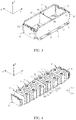
- FIG. 1 is a three-dimensional top view of a battery module according to an embodiment of the present invention
- FIG. 2A is a local detailed three-dimensional view of a part A shown in FIG. 1 , and shows a manner of fixing a first bulge B1 and a first via hole P1 in an embodiment of a battery module
- FIG. 2B shows another manner of fixing a first bulge B1 and a first via hole P1 corresponding to FIG. 2A
- FIG. 3 is another three-dimensional view of the battery module shown in FIG. 1 , in which a plurality of batteries 1 and insulation shields 8 are not shown
- FIG. 4 is another three-dimensional view of the battery module shown in FIG. 1 , in which side plates 2 and a lower plate 4 are not shown
- FIG. 1 is a three-dimensional top view of a battery module according to an embodiment of the present invention
- FIG. 2A is a local detailed three-dimensional view of a part A shown in FIG. 1 , and shows a manner of fixing a first bulge
- FIG. 5 is a three-dimensional bottom view of the battery module shown in FIG. 1 ;
- FIG. 6 is a three-dimensional partial exploded view of the battery module shown in FIG. 5 ;
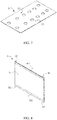
- FIG. 7 is a three-dimensional view of a partition plate of a battery module.
- the battery module according to the present invention includes: a plurality of batteries 1, arranged sequentially along a thickness direction T; side plates 2, disposed on two ends of the plurality of batteries 1 in a width direction W; and a composite pad 3, disposed between two corresponding adjacent batteries 1 along the thickness direction T.
- the battery module further includes: a lower plate 4, disposed and fixed on a lower side of the plurality of batteries 1 in the height direction H; a partition plate 5, located on an upper side of the plurality of batteries 1 in the height direction H; an end plate 6, disposed at either end of the plurality of batteries 1 in the thickness direction T; a cushion 7, disposed between corresponding two adjacent batteries 1 along the thickness direction T; and an insulation shield 8, disposed between the end plate 6 and a battery 1 located at either end of the plurality of batteries 1, and configured to insulate and protect an conductive part (such as main output electrodes (a main positive electrode and a main negative electrode) of the battery module)) in the battery module and corresponding electrical connection parts (such as connectors and wires).
- An interior duct 41 available for flow of a temperature control medium is disposed in the lower plate 4. The temperature control medium may be added in the interior duct 41 to heat up or cool the battery module.
- the battery 1 is a hard-case battery (or called a can-shaped battery), and includes an electrode assembly (not shown), a housing 11, a top cover 12, an electrode post 13, and an explosion-proof valve 14.
- the housing 11 includes major faces 111 and minor side faces 112.
- An accommodation cavity is formed inside the housing 11 to accommodate the electrode assembly and an electrolytic solution.
- the electrode assembly includes a positive electrode plate, a negative electrode plate, and a separator that separates the positive electrode plate from the negative electrode plate.
- the electrode assembly may be formed by winding the positive electrode plate, the negative electrode plate, and the separator, or by stacking the positive electrode plate, the negative electrode plate, and the separator.
- the positive electrode plate and the negative electrode plate both include a current collector and an active substance layer disposed on the current collector.
- a first via hole P1 is disposed on the side plate 2.
- one first via hole P1 is disposed on one side plate 2.
- the side plate 2 is made of a metal material to improve strength.
- the location and quantity of the composite pads 3 may be determined according to actual needs.
- the composite pad 3 may be plural in number.
- the plurality of composite pads may be arranged at equal intervals or variable intervals along the thickness direction T to enhance overall rigidity of the battery module.
- Each composite pad 3 includes a cushion material sheet 31 and a connecting strip 32 disposed around the cushion material sheet 31.
- the composite pad 3 may further include an overlay film layer 33.
- Two first bulges B1 are disposed on the connecting strip 32.
- the two first bulges B1 correspond to the first via holes P1 of the two side plates 2 respectively.
- the two first bulges B1 are inserted into the two first via holes P1 respectively so that the connecting strip 32 is fixedly connected to the two side plates 2.
- a second bulge B2 and/or a third bulge B3 described later may be further disposed on the connecting strip 32, which will be described in detail later.
- the overlay film layer 33 is laid on two sides of the cushion material sheet 31 and the connecting strip 32 in the thickness direction T, and configured to connect the cushion material sheet 31 and the connecting strip 32 together (for example, by heat bonding) and expose any bulge (for example, the first bulge B1, the second bulge B2, and the third bulge B3 described later), so as to enhance the overall strength of the composite pad 3.
- a disposition manner of the connecting strip 32 of each composite pad 3 varies depending on the structure of the side plate 2.
- FIG. 8 is a three-dimensional view of a composite pad of the battery module shown in FIG. 1 according to an embodiment
- FIG. 9 is a three-dimensional exploded view of a composite pad of a battery module shown in FIG. 8
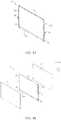
- FIG. 10 is a three-dimensional view of side plates of the battery module shown in FIG. 1 according to an embodiment
- FIG. 11 is a local detailed three-dimensional view of a part B shown in FIG. 10 .
- each side plate 2 includes a main body 21 and an upper bending portion 22.
- the upper bending portion 22 extends from an upper side of the main body 21 toward the plurality of batteries 1 along the width direction W.
- the upper bending portion 22 is located on an upper side of the plurality of batteries 1 in a height direction H.
- the first via hole P1 is disposed on the upper bending portion 22.
- the connecting strip 32 includes an upper connecting strip 321.
- the upper connecting strip 321 is located on an upper side of the cushion material sheet 31.
- the two first bulges B1 are formed on the upper connecting strip 321.
- FIG. 12 is a three-dimensional view of side plates of a battery module according to another embodiment
- FIG. 13 is a three-dimensional exploded view of a composite pad of a battery module according to another embodiment.
- each side plate 2 includes a main body 21 and a lower bending portion 23.
- the lower bending portion 23 extends from a lower side of the main body 21 toward the plurality of batteries 1 along the width direction W.
- the lower bending portion 23 is located on a lower side of the plurality of batteries 1 in the height direction H.
- the first via hole P1 is disposed on the lower bending portion 23.
- the connecting strip 32 includes a lower connecting strip 322.
- the lower connecting strip 322 is located on a lower side of the cushion material sheet 31.
- the two first bulges B1 are formed on the lower connecting strip 322.
- FIG. 14 is a three-dimensional view of side plates of a battery module according to still another embodiment
- FIG. 15 is a three-dimensional view of a composite pad of a battery module according to still another embodiment
- FIG. 16 is a three-dimensional exploded view of a composite pad shown in FIG. 15 .
- each side plate 2 includes a main body 21.
- the first via hole P1 is disposed on the main body 21.
- the connecting strip 32 includes two lateral connecting strips 323.
- Each lateral connecting strip 323 is located on a side of the cushion material sheet 31 in the width direction W.
- the two first bulge B1 are formed on the two lateral connecting strips 323 respectively.
- the disposition manner of the connecting strip 32 of each composite pad 3 varies with the structure of the side plate 2
- the disposition manner of the connecting strip 32 of each composite pad 3 also varies with existence of the lower plate 4.
- the structure of the side plate 2 and the disposition manner of the connecting strip 32 of each composite pad 3 adaptively vary depending on whether the lower plate 4 is configured.
- the lower plate 4 adopts the structure shown in FIG. 6 , that is, a second via hole P2 is disposed on the lower plate 4.
- the side plate 2 adopts the structure shown in FIG. 10 , that is, the side plate 2 includes a main body 21 and an upper bending portion 22.
- the upper bending portion 22 extends from the upper side of the main body 21 toward the plurality of batteries 1 along the width direction W.
- the upper bending portion 22 is located on the upper side of the plurality of batteries 1 in the height direction H.
- the first via hole P1 is disposed on the upper bending portion 22.
- Each composite pad 3 adopts the structure shown in FIG. 8 and FIG.
- the connecting strip 32 of each composite pad 3 includes an upper connecting strip 321 and a lower connecting strip 322.
- the upper connecting strip 321 is located on the upper side of the cushion material sheet 31.
- the two first bulges B1 are formed on the upper connecting strip 321.
- the lower connecting strip 322 is located on the lower side of the cushion material sheet 31.
- the second bulge B2 is formed on the lower connecting strip 322.
- the second bulge B2 is inserted into the second via hole P2 so that the lower connecting strip 322 is fixedly connected to the lower plate 4.
- the two first bulges B1 of the connecting strip 32 are inserted into the first via holes P1 of the two side plates 2 so that the connecting strip 32 is fixedly connected to the two side plates 2.
- the lower plate 4 adopts the structure shown in FIG. 6 , that is, a second via hole P2 is disposed on the lower plate 4.
- the side plate 2 adopts the structure shown in FIG. 14 , that is, the side plate 2 includes a main body 21.
- the first via hole P1 is disposed on the main body 21.
- Each composite pad 3 adopts the structure shown in FIG. 15 and FIG. 16 , that is, the connecting strip 32 of each composite pad 3 includes two lateral connecting strips 323 and a lower connecting strip 322.
- Each lateral connecting strip 323 is located on a side of the cushion material sheet 31 in the width direction W.
- the two first bulges B1 are formed on the two lateral connecting strips 323 respectively.
- the lower connecting strip 322 is located on the lower side of the cushion material sheet 31 and connected between the two lateral connecting strips 323.
- the second bulge B2 is formed on the lower connecting strip 322.
- the second bulge B2 is inserted into the second via hole P2 so that the lower connecting strip 322 is fixedly connected to the lower plate 4.
- the two first bulges B1 of the connecting strip 32 are inserted into the first via holes P1 of the two side plates 2 so that the connecting strip 32 is fixedly connected to the two side plates 2.
- the two first bulges B1 of the connecting strip 32 are inserted into and fixedly connected to the first via holes P1 of the two side plates 2, and the second bulge B2 of the lower connecting strip 322 is inserted into and fixedly connected to the second via hole P2 on the lower plate 4.
- the lower plate 4, the side plate 2, and each composite pad 3 are connected together, and the overall rigidity of the battery module is further enhanced.
- the disposition manner of the connecting strip 32 of each composite pad 3 varies with the structure of the side plate 2
- the disposition manner of the connecting strip 32 of each composite pad 3 also varies with existence of the partition plate 5.
- the structure of the side plate 2 and the disposition manner of the connecting strip 32 of each composite pad 3 adaptively vary depending on whether the partition plate 5 is configured.
- the partition plate 5 adopts the structure shown in FIG. 7 , that is, a third via hole P3 is disposed on the partition plate 5.
- the side plate 2 adopts the structure shown in FIG. 12 , that is, the side plate 2 includes a main body 21 and a lower bending portion 23.
- the lower bending portion 23 extends from the lower side of the main body 21 toward the plurality of batteries 1 along the width direction W.
- the lower bending portion 23 is located on the lower side of the plurality of batteries 1 in the height direction H.
- the first via hole P1 is disposed on the lower bending portion 23.
- Each composite pad 3 adopts the structure shown in FIG. 13 and FIG.
- the connecting strip 32 of each composite pad 3 includes an upper connecting strip 321 and a lower connecting strip 322.
- the lower connecting strip 322 is located on the lower side of the cushion material sheet 31.
- the two first bulges B1 are formed on the lower connecting strip 322.
- the upper connecting strip 321 is located on the upper side of the cushion material sheet 31.
- the third bulge B3 is formed on the upper connecting strip 321.
- the third bulge B3 is inserted into the third via hole P3 so that the upper connecting strip 321 is fixedly connected to the partition plate 5.
- the two first bulges B1 of the connecting strip 32 are inserted into the first via holes P1 of the two side plates 2 so that the connecting strip 32 is fixedly connected to the two side plates 2.
- FIG. 17 is a three-dimensional view of a composite pad of the battery module shown in FIG. 1 according to still another embodiment; and FIG. 18 is a three-dimensional exploded view of a composite pad shown in FIG. 17 .
- the partition plate 5 adopts the structure shown in FIG. 7 , that is, a third via hole P3 is disposed on the partition plate 5.
- the side plate 2 adopts the structure shown in FIG. 14 , that is, the side plate 2 includes a main body 21.
- the first via hole P1 is disposed on the main body 21.
- Each composite pad 3 adopts the structure shown in FIG. 17 and FIG. 18 , that is, the connecting strip 32 of each composite pad 3 includes two lateral connecting strips 323 and an upper connecting strip 321.
- Each lateral connecting strip 323 is located on a side of the cushion material sheet 31 in the width direction W.
- the two first bulges B1 are formed on the two lateral connecting strips 323 respectively.
- the upper connecting strip 321 is located on the upper side of the cushion material sheet 31 and connected between the two lateral connecting strips 323.
- the third bulge B3 is formed on the upper connecting strip 321.
- the third bulge B3 is inserted into the third via hole P3 so that the upper connecting strip 321 is fixedly connected to the partition plate 5.
- the two first bulges B1 of the connecting strip 32 are inserted into the first via holes P1 of the two side plates 2 so that the connecting strip 32 is fixedly connected to the two side plates 2.
- the two first bulges B1 of the connecting strip 32 are inserted into and fixedly connected to the first via holes P1 of the two side plates 2, and the third bulge B3 of the upper connecting strip 321 is inserted into and fixedly connected to the third via hole P3 on the partition plate 5.
- the partition plate 5, the side plate 2, and each composite pad 3 are connected together, and the overall rigidity of the battery module is further enhanced.
- the disposition manner of the connecting strip 32 of each composite pad 3 varies with the structure of the side plate 2
- the disposition manner of the connecting strip 32 of each composite pad 3 also varies with coexistence of the lower plate 4 and the partition plate 5.
- the structure of the side plate 2 and the disposition manner of the connecting strip 32 of each composite pad 3 adaptively vary depending on whether the lower plate 4 and the partition plate 5 are configured.
- the lower plate 4 adopts the structure shown in FIG. 6 , that is, a second via hole P2 is disposed on the lower plate 4.
- the partition plate 5 adopts the structure shown in FIG. 7 , that is, a third via hole P3 is disposed on the partition plate 5.
- the side plate 2 adopts the structure shown in FIG. 14 , that is, the side plate 2 includes a main body 21, and the first via hole P1 is disposed on the main body 21.
- Each composite pad 3 adopts the structure shown in FIG. 17 and FIG. 18 , that is, the connecting strip 32 of each composite pad 3 may include two lateral connecting strips 323, an upper connecting strip 321, and a lower connecting strip 322.
- Each lateral connecting strip 323 is located on a side of the cushion material sheet 31 in the width direction W.
- the two first bulges B1 are formed on the two lateral connecting strips 323 respectively.
- the lower connecting strip 322 is located on the lower side of the cushion material sheet 31 and connected between the two lateral connecting strips 323.
- the second bulge B2 is formed on the lower connecting strip 322.
- the upper connecting strip 321 is located on the upper side of the cushion material sheet 31 and connected between the two lateral connecting strips 323.
- the third bulge B3 is formed on the upper connecting strip 321.
- the two first bulges B1 are inserted into the two first via holes P1 respectively so that the connecting strip 32 is fixedly connected to the two side plates 2.
- the second bulge B2 is inserted into the second via hole P2 so that the lower connecting strip 322 is fixedly connected to the lower plate 4.
- the third bulge B3 is inserted into the third via hole P3 so that the upper connecting strip 321 is fixedly connected to the partition plate 5. In this way, the two side plates 2, the lower plate 4, and the partition plate 5 are connected together, and the overall rigidity of the battery module is further enhanced.
- FIG. 19 is a three-dimensional view of a composite pad of the battery module shown in FIG. 1 according to still another embodiment; and FIG. 20 is a three-dimensional exploded view of a composite pad shown in FIG. 19 .
- the lower plate 4 adopts the structure shown in FIG. 6 , that is, a second via hole P2 is disposed on the lower plate 4.
- the partition plate 5 adopts the structure shown in FIG. 7 , that is, a third via hole P3 is disposed on the partition plate 5.
- the side plate 2 adopts the structure shown in FIG. 12 , that is, the side plate 2 includes a main body 21 and a lower bending portion 23.
- the lower bending portion 23 extends from the lower side of the main body 21 toward the plurality of batteries 1 along the width direction W.
- the lower bending portion 23 is located on the lower side of the plurality of batteries 1 in the height direction H.
- the first via hole P1 is disposed on the lower bending portion 23.
- Each composite pad 3 adopts the structure shown in FIG. 19 and FIG. 20 , that is, the connecting strip 32 of each composite pad 3 includes an upper connecting strip 321 and a lower connecting strip 322.
- the upper connecting strip 321 is located on the upper side of the cushion material sheet 31, and the lower connecting strip 322 is located on the lower side of the cushion material sheet 31.
- the two first bulges B1 are formed on the lower connecting strip 322.
- the second bulge B2 is formed on the lower connecting strip 322, and the third bulge B3 is formed on the upper connecting strip 321.
- the two first bulges B1 are inserted into the two first via holes P1 respectively so that the connecting strip 32 is fixedly connected to the two side plates 2.
- the second bulge B2 is inserted into the second via hole P2 so that the lower connecting strip 322 is fixedly connected to the lower plate 4.
- the third bulge B3 is inserted into the third via hole P3 so that the upper connecting strip 321 is fixedly connected to the partition plate 5. In this way, the two side plates 2, the lower plate 4, and the partition plate 5 are connected together, and the overall rigidity of the battery module is further enhanced.
- the first bulge B1 may be fixed in the first via hole P1 by welding.
- a pad ring (not shown) may be disposed between the first bulge B1 and the corresponding first via hole P1. After being melted by a high temperature, the pad ring fixes the first bulge B1 into the first via hole P1.
- the first bulge B1 is fixed in the first via hole P1 by being inserted into the first via hole P1 and being welded in an everted way.
- a sealing ring (not shown) is disposed between the first bulge B1 and the first via hole P1.
- the manner of fixing between the second bulge B2 and the second via hole P2 is identical to that between the first bulge B1 and the first via hole P1.
- the second bulge B2 may be fixed in the second via hole P2 by welding.
- a pad ring (not shown) may be disposed between the second bulge B2 and the second via hole P2. After being melted by a high temperature, the pad ring fixes the second bulge B2 into the second via hole P2.
- the second bulge B2 may also be fixed in the second via hole P2 by being inserted into the second via hole P2 and being welded in an everted way.
- a sealing ring is disposed between the second bulge B2 and the second via hole P2.
- the third bulge B3 may be fixed in the third via hole P3 by hot-melting the partition plate 5 at the third via hole P3. Specifically, the third bulge B3 is fixed in the second via hole P2 by being inserted into the second via hole P2 and being turned outward.
- each side plate 2 may further include two third bending portions 24 extending from the two ends of the main body 21 in the thickness direction T toward the plurality of batteries 1 along the width direction W respectively.
- Each third bending portion 24 of each side plate 2 is fixed to an end of the corresponding end plate 6 in the width direction W by welding, so as to strengthen the overall rigidity of the battery module frame that includes the side plates 2 and the end plates 6.
- the side plates 2 of the battery module are fixedly connected by the composite pad 3 disposed between two adjacent batteries 1, so as to enhance the overall rigidity of the battery module and improve the capabilities of the battery module in resisting vibration and impact.
Landscapes
- Chemical & Material Sciences (AREA)
- Chemical Kinetics & Catalysis (AREA)
- Electrochemistry (AREA)
- General Chemical & Material Sciences (AREA)
- Engineering & Computer Science (AREA)
- Manufacturing & Machinery (AREA)
- Battery Mounting, Suspending (AREA)
Abstract
Description
- The present invention relates to the field of secondary batteries, and in particular, to a battery module.
- In the design of a large battery module and a long battery module currently, in a process of assembling the battery module, two side plates and two end plates work together to fit major faces of a plurality of batteries with each other. The side plates and end plates are welded to fix the plurality of batteries into a battery module. The following problems are very likely to occur in a conventional design scheme: the side plates on both sides of the battery module are stand-alone, and the two side plates and the two end plates are welded to form a battery module frame. The battery module frame is very fragile in a thickness direction of the battery module. During impact and vibration of the battery module, a middle part of the side plates is deformed greatly so that the side plate is separated from the battery.
- To solve the problem of separation between the side plate and the battery, a conventional method is to apply thicker side plates to increase rigidity of the side plates. However, this increases the weight and cost of the battery module, and loses competitive advantages. Another method is to apply an adhesive to major faces of the battery. For large-sized batteries currently, flatness of the major faces is difficult to control, and a thickness and an area of the adhesive are hardly appropriate. A too thick adhesive layer affects cycle performance. If the adhesive layer is too thin or the adhesive area is insufficient, strength of the adhesive is not enough, and a high rigidity of the battery module is not ensured.
- In view of the defects in existing technologies, an objective of the present invention is to provide a battery module to enhance overall rigidity of the battery module and improve capabilities of the battery module in resisting vibration and impact.
- To achieve the objective, the present invention provides a battery module, including: a plurality of batteries, arranged sequentially along a thickness direction; side plates, disposed on two ends of the plurality of batteries in a width direction; and a composite pad, disposed between two corresponding adjacent batteries along the thickness direction. The composite pad includes a cushion material sheet and a connecting strip disposed around the cushion material sheet. A first bulge is disposed on the connecting strip. A first via hole is disposed on each side plate. The first via hole corresponds to the first bulge. The first bulge is inserted into the first via hole so that the connecting strip is fixedly connected to the side plate.
- In an embodiment, each side plate includes a main body and an upper bending portion. The upper bending portion extends from an upper side of the main body toward the plurality of batteries along the width direction. The upper bending portion is located on an upper side of the plurality of batteries in a height direction. The first via hole is disposed on the upper bending portion. The connecting strip includes an upper connecting strip. The upper connecting strip is located on an upper side of the cushion material sheet. The first bulge is formed on the upper connecting strip. In an embodiment, each side plate includes a main body and a lower bending portion. The lower bending portion extends from a lower side of the main body toward the plurality of batteries along the width direction. The lower bending portion is located on a lower side of the plurality of batteries in a height direction. The first via hole is disposed on the lower bending portion. The connecting strip includes a lower connecting strip. The lower connecting strip is located on a lower side of the cushion material sheet. The first bulge is formed on the lower connecting strip.
- In an embodiment, each side plate includes a main body. The first via hole is disposed on the main body. The connecting strip includes a lateral connecting strip. The lateral connecting strip is located on a side of the cushion material sheet in the width direction. The first bulge is formed on the lateral connecting strip.
- In an embodiment, the connecting strip includes a lower connecting strip. The lower connecting strip is located on a lower side of the cushion material sheet. A second bulge is formed on the lower connecting strip. The battery module further includes a lower plate, disposed and fixed on a lower side of the plurality of batteries in the height direction. A second via hole corresponding to the second bulge is disposed on the lower plate. The second bulge is inserted into the second via hole so that the lower connecting strip is fixedly connected to the lower plate.
- In an embodiment, the connecting strip further includes a lower connecting strip. The lower connecting strip is located on a lower side of the cushion material sheet and connected to the lateral connecting strip. A second bulge is formed on the lower connecting strip. The battery module further includes a lower plate, disposed and fixed on a lower side of the plurality of batteries in the height direction. A second via hole corresponding to the second bulge is disposed on the lower plate. The second bulge is inserted into the second via hole so that the lower connecting strip is fixedly connected to the lower plate.
- In an embodiment, the connecting strip includes an upper connecting strip. The upper connecting strip is located on an upper side of the cushion material sheet. A third bulge is formed on the upper connecting strip. The battery module further includes a partition plate. The partition plate is located on an upper side of the plurality of batteries in the height direction. A third via hole is disposed on the partition plate. The third bulge is inserted into the third via hole so that the upper connecting strip is fixedly connected to the partition plate.
- In an embodiment, the connecting strip further includes an upper connecting strip. The upper connecting strip is located on an upper side of the cushion material sheet and connected to the lateral connecting strip. A third bulge is formed on the upper connecting strip. The battery module further includes a partition plate. The partition plate is located on an upper side of the plurality of batteries in the height direction. A third via hole is disposed on the partition plate. The third bulge is inserted into the third via hole so that the upper connecting strip is fixedly connected to the partition plate.
- In an embodiment, the composite pad further includes an overlay film layer, laid on two sides of the cushion material sheet and the connecting strip in the thickness direction, and configured to connect the cushion material sheet and the connecting strip together and expose the first bulge. In an embodiment, the composite pad further includes an overlay film layer, laid on two sides of the cushion material sheet and the connecting strip in the thickness direction, and configured to connect the cushion material sheet and the connecting strip together and expose the first bulge and the second bulge.
- In an embodiment, the composite pad further includes an overlay film layer, laid on two sides of the cushion material sheet and the connecting strip in the thickness direction, and configured to connect the cushion material sheet and the connecting strip together and expose the first bulge and the third bulge.
- Beneficial effects of this application are as follows:
In the battery module according to the present invention, the side plates of the battery module are fixedly connected by the composite pad disposed between two adjacent batteries, so as to enhance overall rigidity of the battery module and improve capabilities of the battery module in resisting vibration and impact. -
-
FIG. 1 is a three-dimensional top view of a battery module according to an embodiment of the present invention; -
FIG. 2A is a local detailed three-dimensional view of a part A shown inFIG. 1 , and shows a manner of fixing a first bulge and a first via hole in an embodiment of a battery module; -
FIG. 2B shows another manner of fixing a first bulge and a first via hole corresponding toFIG. 2A ; -
FIG. 3 is another three-dimensional view of the battery module shown inFIG. 1 , in which a plurality of batteries and insulation shields are not shown; -
FIG. 4 is another three-dimensional view of the battery module shown inFIG. 1 , in which side plates and a lower plate are not shown; -
FIG. 5 is a three-dimensional bottom view of the battery module shown inFIG. 1 ; -
FIG. 6 is a three-dimensional partial exploded view of the battery module shown inFIG. 5 ; -
FIG. 7 is a three-dimensional view of a partition plate of a battery module; -
FIG. 8 is a three-dimensional view of a composite pad of the battery module shown inFIG. 1 according to an embodiment; -
FIG. 9 is a three-dimensional exploded view of a composite pad of a battery module shown inFIG. 8 ; -
FIG. 10 is a three-dimensional view of side plates of the battery module shown inFIG. 1 according to an embodiment; -
FIG. 11 is a local detailed three-dimensional view of a part B shown inFIG. 10 ; -
FIG. 12 is a three-dimensional view of side plates of a battery module according to another embodiment; -
FIG. 13 is a three-dimensional exploded view of a composite pad of a battery module according to another embodiment; -
FIG. 14 is a three-dimensional view of side plates of a battery module according to still another embodiment; -
FIG. 15 is a three-dimensional view of a composite pad of a battery module according to still another embodiment; -
FIG. 16 is a three-dimensional exploded view of a composite pad shown inFIG. 15 ; -
FIG. 17 is a three-dimensional view of a composite pad of a battery module according to yet another embodiment; -
FIG. 18 is a three-dimensional exploded view of a composite pad shown inFIG. 17 ; -
FIG. 19 is a three-dimensional view of a composite pad of a battery module according to yet another embodiment; and -
FIG. 20 is a three-dimensional exploded view of a composite pad shown inFIG. 19 . - Reference numerals are as follows:
- 1: Battery;
- 11: Housing;
- 111: Major face;
- 112: Minor side face;
- 12: Top cover;
- 13: Electrode post
- 14: Explosion-proof valve
- 2: Side plate;
- 21: Main body;
- 22: Upper bending portion;
- 23: Lower bending portion;
- 24: Third bending portion;
- 3: Composite pad;
- 31: Cushion material sheet;
- 32: Connecting strip;
- 321: Upper connecting strip;
- 322: Lower connecting strip;
- 323: Lateral connecting strip;
- 33: Overlay film layer;
- 4: Lower plate;
- 41: Interior duct;
- 5: Partition plate;
- 6: End plate;
- 7: Cushion;
- 8: Insulation shield;
- B1: First bulge;
- B2: Second bulge;
- B3: Third bulge;
- P1: First via hole;
- P2: Second via hole;
- P3: Third via hole;
- T: Thickness direction;
- W: Width direction; and
- H: Height direction
- The accompanying drawings show embodiments of this application. Understandably, the disclosed embodiments are merely examples of this application, and this application may be implemented in various forms. Therefore, the details disclosed herein are not to be interpreted as limiting, but merely as a basis for the claims and as a representative basis for teaching one skilled in the art to variously employ this application.
-
FIG. 1 is a three-dimensional top view of a battery module according to an embodiment of the present invention;FIG. 2A is a local detailed three-dimensional view of a part A shown inFIG. 1 , and shows a manner of fixing a first bulge B1 and a first via hole P1 in an embodiment of a battery module;FIG. 2B shows another manner of fixing a first bulge B1 and a first via hole P1 corresponding toFIG. 2A ;FIG. 3 is another three-dimensional view of the battery module shown inFIG. 1 , in which a plurality ofbatteries 1 and insulation shields 8 are not shown;FIG. 4 is another three-dimensional view of the battery module shown inFIG. 1 , in whichside plates 2 and a lower plate 4 are not shown;FIG. 5 is a three-dimensional bottom view of the battery module shown inFIG. 1 ;FIG. 6 is a three-dimensional partial exploded view of the battery module shown inFIG. 5 ; andFIG. 7 is a three-dimensional view of a partition plate of a battery module. - The battery module according to the present invention includes: a plurality of
batteries 1, arranged sequentially along a thickness direction T;side plates 2, disposed on two ends of the plurality ofbatteries 1 in a width direction W; and acomposite pad 3, disposed between two correspondingadjacent batteries 1 along the thickness direction T. The battery module further includes: a lower plate 4, disposed and fixed on a lower side of the plurality ofbatteries 1 in the height direction H; a partition plate 5, located on an upper side of the plurality ofbatteries 1 in the height direction H; anend plate 6, disposed at either end of the plurality ofbatteries 1 in the thickness direction T; acushion 7, disposed between corresponding twoadjacent batteries 1 along the thickness direction T; and an insulation shield 8, disposed between theend plate 6 and abattery 1 located at either end of the plurality ofbatteries 1, and configured to insulate and protect an conductive part (such as main output electrodes (a main positive electrode and a main negative electrode) of the battery module)) in the battery module and corresponding electrical connection parts (such as connectors and wires). Aninterior duct 41 available for flow of a temperature control medium is disposed in the lower plate 4. The temperature control medium may be added in theinterior duct 41 to heat up or cool the battery module. - The
battery 1 is a hard-case battery (or called a can-shaped battery), and includes an electrode assembly (not shown), ahousing 11, atop cover 12, anelectrode post 13, and an explosion-proof valve 14. Thehousing 11 includes major faces 111 and minor side faces 112. An accommodation cavity is formed inside thehousing 11 to accommodate the electrode assembly and an electrolytic solution. The electrode assembly includes a positive electrode plate, a negative electrode plate, and a separator that separates the positive electrode plate from the negative electrode plate. The electrode assembly may be formed by winding the positive electrode plate, the negative electrode plate, and the separator, or by stacking the positive electrode plate, the negative electrode plate, and the separator. The positive electrode plate and the negative electrode plate both include a current collector and an active substance layer disposed on the current collector. - In an example shown in the drawing, a first via hole P1 is disposed on the
side plate 2. Specifically, one first via hole P1 is disposed on oneside plate 2. Theside plate 2 is made of a metal material to improve strength. - In the example shown in the drawing, there is just one
composite pad 3 arranged between twoadjacent batteries 1 in the middle of the plurality ofbatteries 1 in the thickness direction T. However, without being limited thereto, the location and quantity of thecomposite pads 3 may be determined according to actual needs. For example, thecomposite pad 3 may be plural in number. The plurality of composite pads may be arranged at equal intervals or variable intervals along the thickness direction T to enhance overall rigidity of the battery module. - Each
composite pad 3 includes acushion material sheet 31 and a connectingstrip 32 disposed around thecushion material sheet 31. Thecomposite pad 3 may further include anoverlay film layer 33. Two first bulges B1 are disposed on the connectingstrip 32. The two first bulges B1 correspond to the first via holes P1 of the twoside plates 2 respectively. The two first bulges B1 are inserted into the two first via holes P1 respectively so that the connectingstrip 32 is fixedly connected to the twoside plates 2. In addition, a second bulge B2 and/or a third bulge B3 described later may be further disposed on the connectingstrip 32, which will be described in detail later. Theoverlay film layer 33 is laid on two sides of thecushion material sheet 31 and the connectingstrip 32 in the thickness direction T, and configured to connect thecushion material sheet 31 and the connectingstrip 32 together (for example, by heat bonding) and expose any bulge (for example, the first bulge B1, the second bulge B2, and the third bulge B3 described later), so as to enhance the overall strength of thecomposite pad 3. - A disposition manner of the connecting
strip 32 of eachcomposite pad 3 varies depending on the structure of theside plate 2. -
FIG. 8 is a three-dimensional view of a composite pad of the battery module shown inFIG. 1 according to an embodiment;FIG. 9 is a three-dimensional exploded view of a composite pad of a battery module shown inFIG. 8 ;FIG. 10 is a three-dimensional view of side plates of the battery module shown inFIG. 1 according to an embodiment; andFIG. 11 is a local detailed three-dimensional view of a part B shown inFIG. 10 . - In the embodiments shown in
FIG. 8 to FIG. 11 , eachside plate 2 includes amain body 21 and anupper bending portion 22. Theupper bending portion 22 extends from an upper side of themain body 21 toward the plurality ofbatteries 1 along the width direction W. Theupper bending portion 22 is located on an upper side of the plurality ofbatteries 1 in a height direction H. The first via hole P1 is disposed on theupper bending portion 22. The connectingstrip 32 includes an upper connectingstrip 321. The upper connectingstrip 321 is located on an upper side of thecushion material sheet 31. The two first bulges B1 are formed on the upper connectingstrip 321. -
FIG. 12 is a three-dimensional view of side plates of a battery module according to another embodiment; andFIG. 13 is a three-dimensional exploded view of a composite pad of a battery module according to another embodiment. - In the embodiments shown in
FIG. 12 andFIG. 13 , eachside plate 2 includes amain body 21 and alower bending portion 23. Thelower bending portion 23 extends from a lower side of themain body 21 toward the plurality ofbatteries 1 along the width direction W. Thelower bending portion 23 is located on a lower side of the plurality ofbatteries 1 in the height direction H. The first via hole P1 is disposed on thelower bending portion 23. The connectingstrip 32 includes a lower connectingstrip 322. The lower connectingstrip 322 is located on a lower side of thecushion material sheet 31. The two first bulges B1 are formed on the lower connectingstrip 322. -
FIG. 14 is a three-dimensional view of side plates of a battery module according to still another embodiment;FIG. 15 is a three-dimensional view of a composite pad of a battery module according to still another embodiment; andFIG. 16 is a three-dimensional exploded view of a composite pad shown inFIG. 15 . - In the embodiments shown in
FIG. 14 to FIG. 16 , eachside plate 2 includes amain body 21. The first via hole P1 is disposed on themain body 21. The connectingstrip 32 includes two lateral connecting strips 323. Eachlateral connecting strip 323 is located on a side of thecushion material sheet 31 in the width direction W. The two first bulge B1 are formed on the twolateral connecting strips 323 respectively. - More than that the disposition manner of the connecting
strip 32 of eachcomposite pad 3 varies with the structure of theside plate 2, the disposition manner of the connectingstrip 32 of eachcomposite pad 3 also varies with existence of the lower plate 4. In other words, the structure of theside plate 2 and the disposition manner of the connectingstrip 32 of eachcomposite pad 3 adaptively vary depending on whether the lower plate 4 is configured. - Specifically, in a manner, when the lower plate 4 is configured, the lower plate 4 adopts the structure shown in
FIG. 6 , that is, a second via hole P2 is disposed on the lower plate 4. Theside plate 2 adopts the structure shown inFIG. 10 , that is, theside plate 2 includes amain body 21 and anupper bending portion 22. Theupper bending portion 22 extends from the upper side of themain body 21 toward the plurality ofbatteries 1 along the width direction W. Theupper bending portion 22 is located on the upper side of the plurality ofbatteries 1 in the height direction H. The first via hole P1 is disposed on theupper bending portion 22. Eachcomposite pad 3 adopts the structure shown inFIG. 8 andFIG. 9 , that is, the connectingstrip 32 of eachcomposite pad 3 includes an upper connectingstrip 321 and a lower connectingstrip 322. The upper connectingstrip 321 is located on the upper side of thecushion material sheet 31. The two first bulges B1 are formed on the upper connectingstrip 321. The lower connectingstrip 322 is located on the lower side of thecushion material sheet 31. The second bulge B2 is formed on the lower connectingstrip 322. The second bulge B2 is inserted into the second via hole P2 so that the lower connectingstrip 322 is fixedly connected to the lower plate 4. As mentioned above, the two first bulges B1 of the connectingstrip 32 are inserted into the first via holes P1 of the twoside plates 2 so that the connectingstrip 32 is fixedly connected to the twoside plates 2. - Other than the foregoing manner in which the lower plate 4 is configured, a different manner may be applied.
- Specifically, when the lower plate 4 is configured, the lower plate 4 adopts the structure shown in
FIG. 6 , that is, a second via hole P2 is disposed on the lower plate 4. Theside plate 2 adopts the structure shown inFIG. 14 , that is, theside plate 2 includes amain body 21. The first via hole P1 is disposed on themain body 21. Eachcomposite pad 3 adopts the structure shown inFIG. 15 and FIG. 16 , that is, the connectingstrip 32 of eachcomposite pad 3 includes two lateral connectingstrips 323 and a lower connectingstrip 322. Eachlateral connecting strip 323 is located on a side of thecushion material sheet 31 in the width direction W. The two first bulges B1 are formed on the twolateral connecting strips 323 respectively. The lower connectingstrip 322 is located on the lower side of thecushion material sheet 31 and connected between the two lateral connecting strips 323. The second bulge B2 is formed on the lower connectingstrip 322. The second bulge B2 is inserted into the second via hole P2 so that the lower connectingstrip 322 is fixedly connected to the lower plate 4. As mentioned above, the two first bulges B1 of the connectingstrip 32 are inserted into the first via holes P1 of the twoside plates 2 so that the connectingstrip 32 is fixedly connected to the twoside plates 2. - Based on the foregoing two connection manners of the lower plate 4, the
side plate 2, and eachcomposite pad 3, the two first bulges B1 of the connectingstrip 32 are inserted into and fixedly connected to the first via holes P1 of the twoside plates 2, and the second bulge B2 of the lower connectingstrip 322 is inserted into and fixedly connected to the second via hole P2 on the lower plate 4. In this way, the lower plate 4, theside plate 2, and eachcomposite pad 3 are connected together, and the overall rigidity of the battery module is further enhanced. - Likewise, more than that the disposition manner of the connecting
strip 32 of eachcomposite pad 3 varies with the structure of theside plate 2, the disposition manner of the connectingstrip 32 of eachcomposite pad 3 also varies with existence of the partition plate 5. In other words, the structure of theside plate 2 and the disposition manner of the connectingstrip 32 of eachcomposite pad 3 adaptively vary depending on whether the partition plate 5 is configured. - Specifically, in a manner, when the partition plate 5 is configured, the partition plate 5 adopts the structure shown in
FIG. 7 , that is, a third via hole P3 is disposed on the partition plate 5. Theside plate 2 adopts the structure shown inFIG. 12 , that is, theside plate 2 includes amain body 21 and alower bending portion 23. Thelower bending portion 23 extends from the lower side of themain body 21 toward the plurality ofbatteries 1 along the width direction W. Thelower bending portion 23 is located on the lower side of the plurality ofbatteries 1 in the height direction H. The first via hole P1 is disposed on thelower bending portion 23. Eachcomposite pad 3 adopts the structure shown inFIG. 13 and FIG. 14 , that is, the connectingstrip 32 of eachcomposite pad 3 includes an upper connectingstrip 321 and a lower connectingstrip 322. The lower connectingstrip 322 is located on the lower side of thecushion material sheet 31. The two first bulges B1 are formed on the lower connectingstrip 322. The upper connectingstrip 321 is located on the upper side of thecushion material sheet 31. The third bulge B3 is formed on the upper connectingstrip 321. The third bulge B3 is inserted into the third via hole P3 so that the upper connectingstrip 321 is fixedly connected to the partition plate 5. The two first bulges B1 of the connectingstrip 32 are inserted into the first via holes P1 of the twoside plates 2 so that the connectingstrip 32 is fixedly connected to the twoside plates 2. - Other than the foregoing manner in which the partition plate 5 is configured, a different manner may be applied.
-
FIG. 17 is a three-dimensional view of a composite pad of the battery module shown inFIG. 1 according to still another embodiment; andFIG. 18 is a three-dimensional exploded view of a composite pad shown inFIG. 17 . - When the partition plate 5 is configured, the partition plate 5 adopts the structure shown in
FIG. 7 , that is, a third via hole P3 is disposed on the partition plate 5. Theside plate 2 adopts the structure shown inFIG. 14 , that is, theside plate 2 includes amain body 21. The first via hole P1 is disposed on themain body 21. Eachcomposite pad 3 adopts the structure shown inFIG. 17 and FIG. 18 , that is, the connectingstrip 32 of eachcomposite pad 3 includes two lateral connectingstrips 323 and an upper connectingstrip 321. Eachlateral connecting strip 323 is located on a side of thecushion material sheet 31 in the width direction W. The two first bulges B1 are formed on the twolateral connecting strips 323 respectively. The upper connectingstrip 321 is located on the upper side of thecushion material sheet 31 and connected between the two lateral connecting strips 323. The third bulge B3 is formed on the upper connectingstrip 321. The third bulge B3 is inserted into the third via hole P3 so that the upper connectingstrip 321 is fixedly connected to the partition plate 5. The two first bulges B1 of the connectingstrip 32 are inserted into the first via holes P1 of the twoside plates 2 so that the connectingstrip 32 is fixedly connected to the twoside plates 2. In the foregoing two manners, the two first bulges B1 of the connectingstrip 32 are inserted into and fixedly connected to the first via holes P1 of the twoside plates 2, and the third bulge B3 of the upper connectingstrip 321 is inserted into and fixedly connected to the third via hole P3 on the partition plate 5. In this way, the partition plate 5, theside plate 2, and eachcomposite pad 3 are connected together, and the overall rigidity of the battery module is further enhanced. Likewise, more than that the disposition manner of the connectingstrip 32 of eachcomposite pad 3 varies with the structure of theside plate 2, the disposition manner of the connectingstrip 32 of eachcomposite pad 3 also varies with coexistence of the lower plate 4 and the partition plate 5. In other words, the structure of theside plate 2 and the disposition manner of the connectingstrip 32 of eachcomposite pad 3 adaptively vary depending on whether the lower plate 4 and the partition plate 5 are configured. - Specifically, in a manner, when both the lower plate 4 and the partition plate 5 are configured, the lower plate 4 adopts the structure shown in
FIG. 6 , that is, a second via hole P2 is disposed on the lower plate 4. The partition plate 5 adopts the structure shown inFIG. 7 , that is, a third via hole P3 is disposed on the partition plate 5. Theside plate 2 adopts the structure shown inFIG. 14 , that is, theside plate 2 includes amain body 21, and the first via hole P1 is disposed on themain body 21. Eachcomposite pad 3 adopts the structure shown inFIG. 17 and FIG. 18 , that is, the connectingstrip 32 of eachcomposite pad 3 may include two lateral connectingstrips 323, an upper connectingstrip 321, and a lower connectingstrip 322. Eachlateral connecting strip 323 is located on a side of thecushion material sheet 31 in the width direction W. The two first bulges B1 are formed on the twolateral connecting strips 323 respectively. The lower connectingstrip 322 is located on the lower side of thecushion material sheet 31 and connected between the two lateral connecting strips 323. The second bulge B2 is formed on the lower connectingstrip 322. The upper connectingstrip 321 is located on the upper side of thecushion material sheet 31 and connected between the two lateral connecting strips 323. The third bulge B3 is formed on the upper connectingstrip 321. The two first bulges B1 are inserted into the two first via holes P1 respectively so that the connectingstrip 32 is fixedly connected to the twoside plates 2. The second bulge B2 is inserted into the second via hole P2 so that the lower connectingstrip 322 is fixedly connected to the lower plate 4. The third bulge B3 is inserted into the third via hole P3 so that the upper connectingstrip 321 is fixedly connected to the partition plate 5. In this way, the twoside plates 2, the lower plate 4, and the partition plate 5 are connected together, and the overall rigidity of the battery module is further enhanced. - Other than the foregoing manner in which the lower plate 4 and the partition plate 5 are configured, a different manner may be applied.
-
FIG. 19 is a three-dimensional view of a composite pad of the battery module shown inFIG. 1 according to still another embodiment; andFIG. 20 is a three-dimensional exploded view of a composite pad shown inFIG. 19 . - Specifically, in another manner, when both the lower plate 4 and the partition plate 5 are configured for the battery module, the lower plate 4 adopts the structure shown in
FIG. 6 , that is, a second via hole P2 is disposed on the lower plate 4. The partition plate 5 adopts the structure shown inFIG. 7 , that is, a third via hole P3 is disposed on the partition plate 5. Theside plate 2 adopts the structure shown inFIG. 12 , that is, theside plate 2 includes amain body 21 and alower bending portion 23. Thelower bending portion 23 extends from the lower side of themain body 21 toward the plurality ofbatteries 1 along the width direction W. Thelower bending portion 23 is located on the lower side of the plurality ofbatteries 1 in the height direction H. The first via hole P1 is disposed on thelower bending portion 23. Eachcomposite pad 3 adopts the structure shown inFIG. 19 and FIG. 20 , that is, the connectingstrip 32 of eachcomposite pad 3 includes an upper connectingstrip 321 and a lower connectingstrip 322. The upper connectingstrip 321 is located on the upper side of thecushion material sheet 31, and the lower connectingstrip 322 is located on the lower side of thecushion material sheet 31. The two first bulges B1 are formed on the lower connectingstrip 322. The second bulge B2 is formed on the lower connectingstrip 322, and the third bulge B3 is formed on the upper connectingstrip 321. The two first bulges B1 are inserted into the two first via holes P1 respectively so that the connectingstrip 32 is fixedly connected to the twoside plates 2. The second bulge B2 is inserted into the second via hole P2 so that the lower connectingstrip 322 is fixedly connected to the lower plate 4. The third bulge B3 is inserted into the third via hole P3 so that the upper connectingstrip 321 is fixedly connected to the partition plate 5. In this way, the twoside plates 2, the lower plate 4, and the partition plate 5 are connected together, and the overall rigidity of the battery module is further enhanced. - In the foregoing embodiments, the first bulge B1 may be fixed in the first via hole P1 by welding. Specifically, referring to the manner of fixing the first bulge B1 to the first via hole P1 shown in
FIG. 2A , a pad ring (not shown) may be disposed between the first bulge B1 and the corresponding first via hole P1. After being melted by a high temperature, the pad ring fixes the first bulge B1 into the first via hole P1. Alternatively, referring to the manner of fixing the first bulge B1 to the first via hole P1 shown inFIG. 2B . The first bulge B1 is fixed in the first via hole P1 by being inserted into the first via hole P1 and being welded in an everted way. To ensure reliable fixing between the first bulge B1 and the first via hole PI, a sealing ring (not shown) is disposed between the first bulge B1 and the first via hole P1. - The manner of fixing between the second bulge B2 and the second via hole P2 is identical to that between the first bulge B1 and the first via hole P1. The second bulge B2 may be fixed in the second via hole P2 by welding. Specifically, a pad ring (not shown) may be disposed between the second bulge B2 and the second via hole P2. After being melted by a high temperature, the pad ring fixes the second bulge B2 into the second via hole P2. The second bulge B2 may also be fixed in the second via hole P2 by being inserted into the second via hole P2 and being welded in an everted way. To ensure reliable fixing between the second bulge B2 and the second via hole P2, a sealing ring is disposed between the second bulge B2 and the second via hole P2.
- The third bulge B3 may be fixed in the third via hole P3 by hot-melting the partition plate 5 at the third via hole P3. Specifically, the third bulge B3 is fixed in the second via hole P2 by being inserted into the second via hole P2 and being turned outward.
- Two ends of the
main body 21 of eachside plate 2 in the thickness direction T are fixed to the corresponding two ends of the twoend plates 6 in the width direction W by welding. Further, as shown inFIG. 1 ,FIG. 3 ,FIG. 5, and FIG. 6 , eachside plate 2 may further include twothird bending portions 24 extending from the two ends of themain body 21 in the thickness direction T toward the plurality ofbatteries 1 along the width direction W respectively. Eachthird bending portion 24 of eachside plate 2 is fixed to an end of thecorresponding end plate 6 in the width direction W by welding, so as to strengthen the overall rigidity of the battery module frame that includes theside plates 2 and theend plates 6. - In conclusion, in the battery module according to the present invention, the
side plates 2 of the battery module are fixedly connected by thecomposite pad 3 disposed between twoadjacent batteries 1, so as to enhance the overall rigidity of the battery module and improve the capabilities of the battery module in resisting vibration and impact. - Although a plurality of exemplary embodiments are described above, this disclosure is not limited to the explicitly disclosed combinations. Therefore, unless otherwise specified herein, the features disclosed herein may be combined together variously. For brevity, other combinations are not described herein.
- The foregoing descriptions are merely exemplary embodiments of this application, but are not intended to limit this application. A person skilled in the art understands that this application may have various modifications and variations. Any modification, equivalent replacement, improvement, and the like made without departing from the spirit and principles of this application fall within the protection scope of this application.
Claims (11)
- A battery module, wherein the battery module comprises:a plurality of batteries (1), arranged sequentially along a thickness direction (T);side plates (2), disposed on two ends of the plurality of batteries (1) in a width direction (W); anda composite pad (3), disposed between two corresponding adjacent batteries (1) along the thickness direction (T), wherein the composite pad (3) comprises a cushion material sheet (31) and a connecting strip (32) disposed around the cushion material sheet (31), and a first bulge (B1) is disposed on the connecting strip (32);a first via hole (P1) is disposed on each side plate (2), and the first via hole (P1) corresponds to the first bulge (B1); andthe first bulge (B1) is inserted into the first via hole (P1) so that the connecting strip (32) is fixedly connected to the side plate (2).
- The battery module according to claim 1, wherein
each side plate (2) comprises a main body (21) and an upper bending portion (22), the upper bending portion (22) extends from an upper side of the main body (21) toward the plurality of batteries (1) along the width direction (W), the upper bending portion (22) is located on an upper side of the plurality of batteries (1) in a height direction (H), and the first via hole (P) is disposed on the upper bending portion (22); and
the connecting strip (32) comprises an upper connecting strip (321), the upper connecting strip (321) is located on an upper side of the cushion material sheet (31), and the first bulge (B1) is formed on the upper connecting strip (321). - The battery module according to claim 1, wherein
each side plate (2) comprises a main body (21) and a lower bending portion (23), the lower bending portion (23) extends from a lower side of the main body (21) toward the plurality of batteries (1) along the width direction (W), the lower bending portion (23) is located on a lower side of the plurality of batteries (1) in a height direction (H), and the first via hole (P1) is disposed on the lower bending portion (23); and
the connecting strip (32) comprises a lower connecting strip (322), the lower connecting strip (322) is located on a lower side of the cushion material sheet (31), and the first bulge (B1) is formed on the lower connecting strip (322). - The battery module according to claim 1, wherein
each side plate (2) comprises a main body (21), and the first via hole (P1) is disposed on the main body (21); and
the connecting strip (32) comprises a lateral connecting strip (323), the lateral connecting strip (323) is located on a side of the cushion material sheet (31) in the width direction (W), and the first bulge (B1) is formed on the lateral connecting strip (323). - The battery module according to claim 2, wherein
the connecting strip (32) comprises a lower connecting strip (322), the lower connecting strip (322) is located on a lower side of the cushion material sheet (31), and a second bulge (B2) is formed on the lower connecting strip (322);
the battery module further comprises a lower plate (4), disposed and fixed on a lower side of the plurality of batteries (1) in the height direction (H); and a second via hole (P2) corresponding to the second bulge (B2) is disposed on the lower plate (4); and
the second bulge (B2) is inserted into the second via hole (P2) so that the lower connecting strip (322) is fixedly connected to the lower plate (4). - The battery module according to claim 4, wherein
the connecting strip (32) further comprises a lower connecting strip (322), the lower connecting strip (322) is located on a lower side of the cushion material sheet (31) and connected to the lateral connecting strip (323), and a second bulge (B2) is formed on the lower connecting strip (322);
the battery module further comprises a lower plate (4), disposed and fixed on a lower side of the plurality of batteries (1) in the height direction (H); and a second via hole (P2) corresponding to the second bulge (B2) is disposed on the lower plate (4); and
the second bulge (B2) is inserted into the second via hole (P2) so that the lower connecting strip (322) is fixedly connected to the lower plate (4). - The battery module according to claim 3, wherein
the connecting strip (32) comprises an upper connecting strip (321), the upper connecting strip (321) is located on an upper side of the cushion material sheet (31), and a third bulge (B3) is formed on the upper connecting strip (321);
the battery module further comprises a partition plate (5), the partition plate (5) is located on an upper side of the plurality of batteries (1) in the height direction (H), and a third via hole (P3) is disposed on the partition plate (5); and
the third bulge (B3) is inserted into the third via hole (P3) so that the upper connecting strip (321) is fixedly connected to the partition plate (5). - The battery module according to claim 4, wherein
the connecting strip (32) further comprises an upper connecting strip (321), the upper connecting strip (321) is located on an upper side of the cushion material sheet (31) and connected to the lateral connecting strip (323), and a third bulge (B3) is formed on the upper connecting strip (321);
the battery module further comprises a partition plate (5), the partition plate (5) is located on an upper side of the plurality of batteries (1) in the height direction (H), and a third via hole (P3) is disposed on the partition plate (5); and
the third bulge (B3) is inserted into the third via hole (P3) so that the upper connecting strip (321) is fixedly connected to the partition plate (5). - The battery module according to any one of claims 1 to 4, wherein the composite pad (3) further comprises an overlay film layer (33), laid on two sides of the cushion material sheet (31) and the connecting strip (32) in the thickness direction (T), and configured to connect the cushion material sheet (31) and the connecting strip (32) together and expose the first bulge (B1).
- The battery module according to any one of claims 5 to 6, wherein the composite pad (3) further comprises an overlay film layer (33), laid on two sides of the cushion material sheet (31) and the connecting strip (32) in the thickness direction (T), and configured to connect the cushion material sheet (31) and the connecting strip (32) together and expose the first bulge (B1) and the second bulge (B2).
- The battery module according to any one of claims 7 to 8, wherein the composite pad (3) further comprises an overlay film layer (33), laid on two sides of the cushion material sheet (31) and the connecting strip (32) in the thickness direction (T), and configured to connect the cushion material sheet (31) and the connecting strip (32) together and expose the first bulge (B1) and the third bulge (B3).
Applications Claiming Priority (2)
| Application Number | Priority Date | Filing Date | Title |
|---|---|---|---|
| CN201821934967.7U CN209104207U (en) | 2018-11-22 | 2018-11-22 | battery module |
| PCT/CN2019/091350 WO2020103442A1 (en) | 2018-11-22 | 2019-06-14 | Battery module |
Publications (3)
| Publication Number | Publication Date |
|---|---|
| EP3859818A1 true EP3859818A1 (en) | 2021-08-04 |
| EP3859818A4 EP3859818A4 (en) | 2021-12-01 |
| EP3859818B1 EP3859818B1 (en) | 2025-05-14 |
Family
ID=67161090
Family Applications (1)
| Application Number | Title | Priority Date | Filing Date |
|---|---|---|---|
| EP19887806.8A Active EP3859818B1 (en) | 2018-11-22 | 2019-06-14 | Battery module |
Country Status (4)
| Country | Link |
|---|---|
| US (1) | US12191513B2 (en) |
| EP (1) | EP3859818B1 (en) |
| CN (1) | CN209104207U (en) |
| WO (1) | WO2020103442A1 (en) |
Cited By (2)
| Publication number | Priority date | Publication date | Assignee | Title |
|---|---|---|---|---|
| EP3846243A4 (en) * | 2019-09-29 | 2022-06-15 | Dongguan Amperex Technology Limited | Battery module unit, battery module, energy storage system, and electric vehicle |
| EP4525151A1 (en) * | 2023-09-05 | 2025-03-19 | Samsung Sdi Co., Ltd. | Battery module |
Families Citing this family (2)
| Publication number | Priority date | Publication date | Assignee | Title |
|---|---|---|---|---|
| CN113795966B (en) * | 2019-11-25 | 2024-07-05 | 株式会社Lg新能源 | Battery module, method for manufacturing the battery module, and battery pack |
| JP2023136828A (en) * | 2022-03-17 | 2023-09-29 | 株式会社Gsユアサ | Power storage device |
Family Cites Families (10)
| Publication number | Priority date | Publication date | Assignee | Title |
|---|---|---|---|---|
| JP5666274B2 (en) * | 2010-12-04 | 2015-02-12 | 三洋電機株式会社 | Battery pack and vehicle equipped with the same |
| JP5960289B2 (en) * | 2013-01-10 | 2016-08-02 | 日立オートモティブシステムズ株式会社 | Battery module |
| JP6174388B2 (en) | 2013-06-19 | 2017-08-02 | 日立オートモティブシステムズ株式会社 | Battery module |
| CN203631621U (en) * | 2013-12-05 | 2014-06-04 | 宁德时代新能源科技有限公司 | Battery module |
| WO2017017913A1 (en) * | 2015-07-30 | 2017-02-02 | 三洋電機株式会社 | Power supply device and vehicle using same |
| CN106299188A (en) * | 2016-09-29 | 2017-01-04 | 常州普莱德新能源电池科技有限公司 | A kind of soft package battery module used for electric vehicle |
| KR101912015B1 (en) | 2016-11-15 | 2018-10-25 | 엘지전자 주식회사 | Battery Pack |
| JP6861045B2 (en) * | 2017-02-09 | 2021-04-21 | 株式会社エンビジョンAescジャパン | Assembled battery, battery pack, manufacturing method of assembled battery and manufacturing method of battery pack |
| CN207818692U (en) * | 2018-01-19 | 2018-09-04 | 宁德时代新能源科技股份有限公司 | battery module |
| CN207967119U (en) * | 2018-04-02 | 2018-10-12 | 宁德时代新能源科技股份有限公司 | Framework and battery modules |
-
2018
- 2018-11-22 CN CN201821934967.7U patent/CN209104207U/en active Active
-
2019
- 2019-06-14 EP EP19887806.8A patent/EP3859818B1/en active Active
- 2019-06-14 WO PCT/CN2019/091350 patent/WO2020103442A1/en not_active Ceased
-
2021
- 2021-05-10 US US17/316,528 patent/US12191513B2/en active Active
Cited By (2)
| Publication number | Priority date | Publication date | Assignee | Title |
|---|---|---|---|---|
| EP3846243A4 (en) * | 2019-09-29 | 2022-06-15 | Dongguan Amperex Technology Limited | Battery module unit, battery module, energy storage system, and electric vehicle |
| EP4525151A1 (en) * | 2023-09-05 | 2025-03-19 | Samsung Sdi Co., Ltd. | Battery module |
Also Published As
| Publication number | Publication date |
|---|---|
| CN209104207U (en) | 2019-07-12 |
| WO2020103442A1 (en) | 2020-05-28 |
| US20210265692A1 (en) | 2021-08-26 |
| EP3859818B1 (en) | 2025-05-14 |
| US12191513B2 (en) | 2025-01-07 |
| EP3859818A4 (en) | 2021-12-01 |
Similar Documents
| Publication | Publication Date | Title |
|---|---|---|
| US12191513B2 (en) | Battery module | |
| KR102549509B1 (en) | Secondary battery, battery module, battery pack, device and manufacturing method thereof | |
| US20090023057A1 (en) | Pouch type battery pack | |
| US9017852B2 (en) | Secondary battery | |
| CN103875095B (en) | Secondary battery | |
| CN209786120U (en) | Secondary batteries and battery modules | |
| KR101451051B1 (en) | Secondary battery | |
| KR20130110048A (en) | Rechargeable battery | |
| JP2013214497A (en) | Battery pack | |
| US9048487B2 (en) | Secondary battery and manufacturing method thereof | |
| US10090568B2 (en) | Battery assembly | |
| WO2019003928A1 (en) | Bus bar and battery laminate | |
| JP2014527262A (en) | Single cell and battery for battery | |
| JP6573644B2 (en) | Electricity storage device | |
| KR20150033178A (en) | Pouch type secondary battery and secondary battery module comprising the same | |
| CN214898779U (en) | Power Battery | |
| KR20150057819A (en) | Rechargeable battery | |
| CN112864539A (en) | Power battery | |
| JP4062846B2 (en) | Lead-acid battery and manufacturing method thereof | |
| KR102490864B1 (en) | Secondary battery | |
| KR101623127B1 (en) | Rechargeable battery | |
| CN224053236U (en) | Battery cover plate, battery pack and vehicle | |
| EP3859817B1 (en) | Battery module | |
| WO2013018552A1 (en) | Battery | |
| KR20160134064A (en) | Rechargeable battery module |
Legal Events
| Date | Code | Title | Description |
|---|---|---|---|
| STAA | Information on the status of an ep patent application or granted ep patent |
Free format text: STATUS: THE INTERNATIONAL PUBLICATION HAS BEEN MADE |
|
| PUAI | Public reference made under article 153(3) epc to a published international application that has entered the european phase |
Free format text: ORIGINAL CODE: 0009012 |
|
| STAA | Information on the status of an ep patent application or granted ep patent |
Free format text: STATUS: REQUEST FOR EXAMINATION WAS MADE |
|
| 17P | Request for examination filed |
Effective date: 20210429 |
|
| AK | Designated contracting states |
Kind code of ref document: A1 Designated state(s): AL AT BE BG CH CY CZ DE DK EE ES FI FR GB GR HR HU IE IS IT LI LT LU LV MC MK MT NL NO PL PT RO RS SE SI SK SM TR |
|
| REG | Reference to a national code |
Ref country code: DE Ref legal event code: R079 Free format text: PREVIOUS MAIN CLASS: H01M0002100000 Ipc: H01M0050209000 Ref country code: DE Ref legal event code: R079 Ref document number: 602019070090 Country of ref document: DE Free format text: PREVIOUS MAIN CLASS: H01M0002100000 Ipc: H01M0050209000 |
|
| A4 | Supplementary search report drawn up and despatched |
Effective date: 20211029 |
|
| RIC1 | Information provided on ipc code assigned before grant |
Ipc: H01M 50/20 20210101ALI20211025BHEP Ipc: H01M 50/242 20210101ALI20211025BHEP Ipc: H01M 50/289 20210101ALI20211025BHEP Ipc: H01M 50/209 20210101AFI20211025BHEP |
|
| DAV | Request for validation of the european patent (deleted) | ||
| DAX | Request for extension of the european patent (deleted) | ||
| STAA | Information on the status of an ep patent application or granted ep patent |
Free format text: STATUS: EXAMINATION IS IN PROGRESS |
|
| 17Q | First examination report despatched |
Effective date: 20221129 |
|
| RAP1 | Party data changed (applicant data changed or rights of an application transferred) |
Owner name: CONTEMPORARY AMPEREX TECHNOLOGY(HONG KONG) LIMITED |
|
| REG | Reference to a national code |
Ref country code: DE Ref legal event code: R079 Free format text: PREVIOUS MAIN CLASS: H01M0050209000 Ipc: H01M0050204000 Ref country code: DE Ref legal event code: R079 Ref document number: 602019070090 Country of ref document: DE Free format text: PREVIOUS MAIN CLASS: H01M0050209000 Ipc: H01M0050204000 |
|
| GRAP | Despatch of communication of intention to grant a patent |
Free format text: ORIGINAL CODE: EPIDOSNIGR1 |
|
| STAA | Information on the status of an ep patent application or granted ep patent |
Free format text: STATUS: GRANT OF PATENT IS INTENDED |
|
| RIC1 | Information provided on ipc code assigned before grant |
Ipc: H01M 10/04 20060101ALI20241205BHEP Ipc: H01M 50/242 20210101ALI20241205BHEP Ipc: H01M 50/289 20210101ALI20241205BHEP Ipc: H01M 50/209 20210101ALI20241205BHEP Ipc: H01M 50/204 20210101AFI20241205BHEP |
|
| INTG | Intention to grant announced |
Effective date: 20250103 |
|
| GRAS | Grant fee paid |
Free format text: ORIGINAL CODE: EPIDOSNIGR3 |
|
| GRAA | (expected) grant |
Free format text: ORIGINAL CODE: 0009210 |
|
| STAA | Information on the status of an ep patent application or granted ep patent |
Free format text: STATUS: THE PATENT HAS BEEN GRANTED |
|
| AK | Designated contracting states |
Kind code of ref document: B1 Designated state(s): AL AT BE BG CH CY CZ DE DK EE ES FI FR GB GR HR HU IE IS IT LI LT LU LV MC MK MT NL NO PL PT RO RS SE SI SK SM TR |
|
| REG | Reference to a national code |
Ref country code: GB Ref legal event code: FG4D |
|
| REG | Reference to a national code |
Ref country code: CH Ref legal event code: EP |
|
| REG | Reference to a national code |
Ref country code: DE Ref legal event code: R096 Ref document number: 602019070090 Country of ref document: DE |
|
| REG | Reference to a national code |
Ref country code: IE Ref legal event code: FG4D |
|
| PGFP | Annual fee paid to national office [announced via postgrant information from national office to epo] |
Ref country code: DE Payment date: 20250625 Year of fee payment: 7 |
|
| PGFP | Annual fee paid to national office [announced via postgrant information from national office to epo] |
Ref country code: GB Payment date: 20250620 Year of fee payment: 7 |
|
| PGFP | Annual fee paid to national office [announced via postgrant information from national office to epo] |
Ref country code: FR Payment date: 20250620 Year of fee payment: 7 |
|
| P01 | Opt-out of the competence of the unified patent court (upc) registered |
Free format text: CASE NUMBER: APP_28833/2025 Effective date: 20250617 |
|
| REG | Reference to a national code |
Ref country code: NL Ref legal event code: MP Effective date: 20250514 |
|
| PG25 | Lapsed in a contracting state [announced via postgrant information from national office to epo] |
Ref country code: FI Free format text: LAPSE BECAUSE OF FAILURE TO SUBMIT A TRANSLATION OF THE DESCRIPTION OR TO PAY THE FEE WITHIN THE PRESCRIBED TIME-LIMIT Effective date: 20250514 Ref country code: PT Free format text: LAPSE BECAUSE OF FAILURE TO SUBMIT A TRANSLATION OF THE DESCRIPTION OR TO PAY THE FEE WITHIN THE PRESCRIBED TIME-LIMIT Effective date: 20250915 Ref country code: ES Free format text: LAPSE BECAUSE OF FAILURE TO SUBMIT A TRANSLATION OF THE DESCRIPTION OR TO PAY THE FEE WITHIN THE PRESCRIBED TIME-LIMIT Effective date: 20250514 |
|
| REG | Reference to a national code |
Ref country code: LT Ref legal event code: MG9D |
|
| PG25 | Lapsed in a contracting state [announced via postgrant information from national office to epo] |
Ref country code: NO Free format text: LAPSE BECAUSE OF FAILURE TO SUBMIT A TRANSLATION OF THE DESCRIPTION OR TO PAY THE FEE WITHIN THE PRESCRIBED TIME-LIMIT Effective date: 20250814 Ref country code: GR Free format text: LAPSE BECAUSE OF FAILURE TO SUBMIT A TRANSLATION OF THE DESCRIPTION OR TO PAY THE FEE WITHIN THE PRESCRIBED TIME-LIMIT Effective date: 20250815 |
|
| PG25 | Lapsed in a contracting state [announced via postgrant information from national office to epo] |
Ref country code: PL Free format text: LAPSE BECAUSE OF FAILURE TO SUBMIT A TRANSLATION OF THE DESCRIPTION OR TO PAY THE FEE WITHIN THE PRESCRIBED TIME-LIMIT Effective date: 20250514 Ref country code: NL Free format text: LAPSE BECAUSE OF FAILURE TO SUBMIT A TRANSLATION OF THE DESCRIPTION OR TO PAY THE FEE WITHIN THE PRESCRIBED TIME-LIMIT Effective date: 20250514 |
|
| REG | Reference to a national code |
Ref country code: AT Ref legal event code: MK05 Ref document number: 1795619 Country of ref document: AT Kind code of ref document: T Effective date: 20250514 |
|
| PG25 | Lapsed in a contracting state [announced via postgrant information from national office to epo] |
Ref country code: BG Free format text: LAPSE BECAUSE OF FAILURE TO SUBMIT A TRANSLATION OF THE DESCRIPTION OR TO PAY THE FEE WITHIN THE PRESCRIBED TIME-LIMIT Effective date: 20250514 |
|
| PG25 | Lapsed in a contracting state [announced via postgrant information from national office to epo] |
Ref country code: HR Free format text: LAPSE BECAUSE OF FAILURE TO SUBMIT A TRANSLATION OF THE DESCRIPTION OR TO PAY THE FEE WITHIN THE PRESCRIBED TIME-LIMIT Effective date: 20250514 |
|
| PG25 | Lapsed in a contracting state [announced via postgrant information from national office to epo] |
Ref country code: AT Free format text: LAPSE BECAUSE OF FAILURE TO SUBMIT A TRANSLATION OF THE DESCRIPTION OR TO PAY THE FEE WITHIN THE PRESCRIBED TIME-LIMIT Effective date: 20250514 |
|
| PG25 | Lapsed in a contracting state [announced via postgrant information from national office to epo] |
Ref country code: RS Free format text: LAPSE BECAUSE OF FAILURE TO SUBMIT A TRANSLATION OF THE DESCRIPTION OR TO PAY THE FEE WITHIN THE PRESCRIBED TIME-LIMIT Effective date: 20250814 |
|
| PG25 | Lapsed in a contracting state [announced via postgrant information from national office to epo] |
Ref country code: IS Free format text: LAPSE BECAUSE OF FAILURE TO SUBMIT A TRANSLATION OF THE DESCRIPTION OR TO PAY THE FEE WITHIN THE PRESCRIBED TIME-LIMIT Effective date: 20250914 |
|
| PG25 | Lapsed in a contracting state [announced via postgrant information from national office to epo] |
Ref country code: LV Free format text: LAPSE BECAUSE OF FAILURE TO SUBMIT A TRANSLATION OF THE DESCRIPTION OR TO PAY THE FEE WITHIN THE PRESCRIBED TIME-LIMIT Effective date: 20250514 |
|
| PG25 | Lapsed in a contracting state [announced via postgrant information from national office to epo] |
Ref country code: SM Free format text: LAPSE BECAUSE OF FAILURE TO SUBMIT A TRANSLATION OF THE DESCRIPTION OR TO PAY THE FEE WITHIN THE PRESCRIBED TIME-LIMIT Effective date: 20250514 Ref country code: DK Free format text: LAPSE BECAUSE OF FAILURE TO SUBMIT A TRANSLATION OF THE DESCRIPTION OR TO PAY THE FEE WITHIN THE PRESCRIBED TIME-LIMIT Effective date: 20250514 |
|
| PG25 | Lapsed in a contracting state [announced via postgrant information from national office to epo] |
Ref country code: CZ Free format text: LAPSE BECAUSE OF FAILURE TO SUBMIT A TRANSLATION OF THE DESCRIPTION OR TO PAY THE FEE WITHIN THE PRESCRIBED TIME-LIMIT Effective date: 20250514 |
|
| PG25 | Lapsed in a contracting state [announced via postgrant information from national office to epo] |
Ref country code: EE Free format text: LAPSE BECAUSE OF FAILURE TO SUBMIT A TRANSLATION OF THE DESCRIPTION OR TO PAY THE FEE WITHIN THE PRESCRIBED TIME-LIMIT Effective date: 20250514 |
|
| PG25 | Lapsed in a contracting state [announced via postgrant information from national office to epo] |
Ref country code: SK Free format text: LAPSE BECAUSE OF FAILURE TO SUBMIT A TRANSLATION OF THE DESCRIPTION OR TO PAY THE FEE WITHIN THE PRESCRIBED TIME-LIMIT Effective date: 20250514 Ref country code: RO Free format text: LAPSE BECAUSE OF FAILURE TO SUBMIT A TRANSLATION OF THE DESCRIPTION OR TO PAY THE FEE WITHIN THE PRESCRIBED TIME-LIMIT Effective date: 20250514 |
|
| REG | Reference to a national code |
Ref country code: CH Ref legal event code: H13 Free format text: ST27 STATUS EVENT CODE: U-0-0-H10-H13 (AS PROVIDED BY THE NATIONAL OFFICE) Effective date: 20260127 |
|
| PG25 | Lapsed in a contracting state [announced via postgrant information from national office to epo] |
Ref country code: IT Free format text: LAPSE BECAUSE OF FAILURE TO SUBMIT A TRANSLATION OF THE DESCRIPTION OR TO PAY THE FEE WITHIN THE PRESCRIBED TIME-LIMIT Effective date: 20250514 |
|
| PG25 | Lapsed in a contracting state [announced via postgrant information from national office to epo] |
Ref country code: LU Free format text: LAPSE BECAUSE OF NON-PAYMENT OF DUE FEES Effective date: 20250614 |
|
| REG | Reference to a national code |
Ref country code: DE Ref legal event code: R097 Ref document number: 602019070090 Country of ref document: DE |
|
| PG25 | Lapsed in a contracting state [announced via postgrant information from national office to epo] |
Ref country code: MC Free format text: LAPSE BECAUSE OF FAILURE TO SUBMIT A TRANSLATION OF THE DESCRIPTION OR TO PAY THE FEE WITHIN THE PRESCRIBED TIME-LIMIT Effective date: 20250514 |
|
| REG | Reference to a national code |
Ref country code: BE Ref legal event code: MM Effective date: 20250630 |
|
| PLBE | No opposition filed within time limit |
Free format text: ORIGINAL CODE: 0009261 |
|
| STAA | Information on the status of an ep patent application or granted ep patent |
Free format text: STATUS: NO OPPOSITION FILED WITHIN TIME LIMIT |
|
| REG | Reference to a national code |
Ref country code: CH Ref legal event code: L10 Free format text: ST27 STATUS EVENT CODE: U-0-0-L10-L00 (AS PROVIDED BY THE NATIONAL OFFICE) Effective date: 20260325 |
|
| PG25 | Lapsed in a contracting state [announced via postgrant information from national office to epo] |
Ref country code: IE Free format text: LAPSE BECAUSE OF NON-PAYMENT OF DUE FEES Effective date: 20250614 |
|
| PG25 | Lapsed in a contracting state [announced via postgrant information from national office to epo] |
Ref country code: BE Free format text: LAPSE BECAUSE OF NON-PAYMENT OF DUE FEES Effective date: 20250630 |
|
| 26N | No opposition filed |
Effective date: 20260217 |
|
| PG25 | Lapsed in a contracting state [announced via postgrant information from national office to epo] |
Ref country code: CH Free format text: LAPSE BECAUSE OF NON-PAYMENT OF DUE FEES Effective date: 20250630 |