EP3859707A1 - Road sign recognition device - Google Patents
Road sign recognition device Download PDFInfo
- Publication number
- EP3859707A1 EP3859707A1 EP19864405.6A EP19864405A EP3859707A1 EP 3859707 A1 EP3859707 A1 EP 3859707A1 EP 19864405 A EP19864405 A EP 19864405A EP 3859707 A1 EP3859707 A1 EP 3859707A1
- Authority
- EP
- European Patent Office
- Prior art keywords
- sign
- road sign
- information
- road
- recognition
- Prior art date
- Legal status (The legal status is an assumption and is not a legal conclusion. Google has not performed a legal analysis and makes no representation as to the accuracy of the status listed.)
- Granted
Links
Images






Classifications
-
- G—PHYSICS
- G08—SIGNALLING
- G08G—TRAFFIC CONTROL SYSTEMS
- G08G1/00—Traffic control systems for road vehicles
- G08G1/09—Arrangements for giving variable traffic instructions
- G08G1/0962—Arrangements for giving variable traffic instructions having an indicator mounted inside the vehicle, e.g. giving voice messages
- G08G1/09623—Systems involving the acquisition of information from passive traffic signs by means mounted on the vehicle
-
- G—PHYSICS
- G06—COMPUTING OR CALCULATING; COUNTING
- G06V—IMAGE OR VIDEO RECOGNITION OR UNDERSTANDING
- G06V10/00—Arrangements for image or video recognition or understanding
- G06V10/20—Image preprocessing
- G06V10/22—Image preprocessing by selection of a specific region containing or referencing a pattern; Locating or processing of specific regions to guide the detection or recognition
- G06V10/23—Image preprocessing by selection of a specific region containing or referencing a pattern; Locating or processing of specific regions to guide the detection or recognition based on positionally close patterns or neighbourhood relationships
-
- G—PHYSICS
- G06—COMPUTING OR CALCULATING; COUNTING
- G06V—IMAGE OR VIDEO RECOGNITION OR UNDERSTANDING
- G06V10/00—Arrangements for image or video recognition or understanding
- G06V10/40—Extraction of image or video features
- G06V10/44—Local feature extraction by analysis of parts of the pattern, e.g. by detecting edges, contours, loops, corners, strokes or intersections; Connectivity analysis, e.g. of connected components
-
- G—PHYSICS
- G06—COMPUTING OR CALCULATING; COUNTING
- G06V—IMAGE OR VIDEO RECOGNITION OR UNDERSTANDING
- G06V10/00—Arrangements for image or video recognition or understanding
- G06V10/70—Arrangements for image or video recognition or understanding using pattern recognition or machine learning
- G06V10/768—Arrangements for image or video recognition or understanding using pattern recognition or machine learning using context analysis, e.g. recognition aided by known co-occurring patterns
-
- G—PHYSICS
- G06—COMPUTING OR CALCULATING; COUNTING
- G06V—IMAGE OR VIDEO RECOGNITION OR UNDERSTANDING
- G06V10/00—Arrangements for image or video recognition or understanding
- G06V10/70—Arrangements for image or video recognition or understanding using pattern recognition or machine learning
- G06V10/77—Processing image or video features in feature spaces; using data integration or data reduction, e.g. principal component analysis [PCA] or independent component analysis [ICA] or self-organising maps [SOM]; Blind source separation
- G06V10/80—Fusion, i.e. combining data from various sources at the sensor level, preprocessing level, feature extraction level or classification level
-
- G—PHYSICS
- G06—COMPUTING OR CALCULATING; COUNTING
- G06V—IMAGE OR VIDEO RECOGNITION OR UNDERSTANDING
- G06V20/00—Scenes; Scene-specific elements
- G06V20/50—Context or environment of the image
- G06V20/56—Context or environment of the image exterior to a vehicle by using sensors mounted on the vehicle
- G06V20/58—Recognition of moving objects or obstacles, e.g. vehicles or pedestrians; Recognition of traffic objects, e.g. traffic signs, traffic lights or roads
- G06V20/582—Recognition of moving objects or obstacles, e.g. vehicles or pedestrians; Recognition of traffic objects, e.g. traffic signs, traffic lights or roads of traffic signs
Definitions
- Step S127 the vehicle control information determination unit 104 identifies the type of the auxiliary sign used for determining the vehicle control information by using the combination information acquired from the road sign data recording unit 103 in Step S126 with a priority over the recognition result of the auxiliary sign of the road sign recognition unit 102 (Step S129) . In this manner, the type of the auxiliary sign used for determining the vehicle control information can be accurately identified even when the recognition precision of the auxiliary sign is low.
- the combination information T152 and T153 also describe the degree of attachment of an auxiliary sign indicating the likelihood of attachment of the auxiliary sign for each of main signs.
- the value of the degree of attachment of the auxiliary sign in the combination information T152 is 8 and the value of the degree of attachment of the auxiliary sign in the combination information T153 is 1, and thus, this indicates that the maximum speed 50 km sign is more likely to be attached with the auxiliary sign than the maximum speed 100 km sign.
- Step S207 the vehicle control information determination unit 204 acquires road sign information based on the recognition result of Step S203 from the road sign data recording unit 203.
- the road sign information corresponding to the type of the main sign identified in Step S203 is read from the road sign information stored in the road sign data recording unit 203.
- the start sign having the second highest recognition score in the recognition result T221 has a combination condition is "o" for the general road in the combination information T212 in FIG. 15 , which indicates that the start sign can be attached to the maximum speed 50 km sign on the general road indicated by the acquired travel environment information. Therefore, the start sign is identified as the type of the auxiliary sign T202. As a result, a correct recognition result is obtained for the auxiliary sign T202.
- FIG. 20 is a functional block diagram illustrating a configuration of a road sign recognition device according to the eighth embodiment of the present invention.
- a road sign recognition device 10B of the present embodiment is connected to the imaging device 20 and the vehicle control device 30, which is similar to the road sign recognition devices 10 and 10A described with reference to FIGS. 1 and 12 .
- the road sign recognition device 10B of the present embodiment includes an image acquisition unit 301, a road sign recognition unit 302, a road sign data recording unit 303, a vehicle control information determination unit 304, a travel environment acquisition unit 305, and a road sign information rewriting unit 306.
- the road sign information stored in the road sign data recording unit 303 is rewritten in the road sign recognition device 10B of the present embodiment. As a result, a road sign can be accurately recognized even if an installation condition of the road sign changes.
Landscapes
- Engineering & Computer Science (AREA)
- Theoretical Computer Science (AREA)
- General Physics & Mathematics (AREA)
- Physics & Mathematics (AREA)
- Multimedia (AREA)
- Computer Vision & Pattern Recognition (AREA)
- Artificial Intelligence (AREA)
- Databases & Information Systems (AREA)
- Evolutionary Computation (AREA)
- General Health & Medical Sciences (AREA)
- Medical Informatics (AREA)
- Software Systems (AREA)
- Computing Systems (AREA)
- Health & Medical Sciences (AREA)
- Traffic Control Systems (AREA)
- Image Analysis (AREA)
- Image Processing (AREA)
Abstract
Description
- The present invention relates to a road sign recognition device.
- In order to realize automatic driving and prevent traffic accidents, there is a great deal of interest in road sign recognition techniques that recognize road signs in a traveling vehicle and uses recognition results to control the vehicle.
- Some road signs are combinations of main signs indicating various regulation contents on vehicles and auxiliary signs indicating supplementary information on the main signs, such as conditions under which the regulation contents of the main signs are applied. When a vehicle is controlled by recognizing such a road sign in which a main sign and an auxiliary sign are combined in this manner, it is important to determine the validity of a regulation content of the main sign for the vehicle based on the recognition result of the auxiliary sign.
- Regarding the recognition of the road sign in which the main sign and the auxiliary sign are combined, for example,
PTL 1 discloses a sign recognition device that includes: a sign effective range data recording unit for prestoring effective range conditions shown by a main sign and an auxiliary sign; a sign recognition unit for recognizing a main sign and an auxiliary sign by using a captured image of a roadway in front of a vehicle; and a sign effective range determining unit for determining whether or not the vehicle is staying in an effective range specified with the main sign and the auxiliary sign which have been recognized by the sign recognition unit by using the effective range conditions stored in the sign effective range data recording unit, the vehicle information, and map information. - PTL 1:
JP 2010-282278 A - In the sign recognition device of
PTL 1, the road sign needs to be accurately recognized as the premise of correctly determining whether or not the vehicle is staying in the effective range of the road sign. However, the auxiliary sign usually has smaller characters or patterns than the main sign, and is likely to cause misrecognition. Therefore, when the sign recognition device ofPTL 1 is used for controlling a vehicle, there is a problem that it is difficult to correctly determine the control content from the recognition result of the road sign. - In view of such a problem, an object of the present invention is to provide a technique for correctly determining the control content of a vehicle from a recognition result of a road sign.
- A road sign recognition device according to the present invention includes: an image acquisition unit that acquires an image; a road sign recognition unit that recognizes a road sign from the image acquired by the image acquisition unit; a road sign data recording unit that stores road sign information about a combination of a plurality of road signs; and a vehicle control information determination unit that determines vehicle control information used for controlling a host vehicle. The vehicle control information determination unit determines the vehicle control information based on the road sign recognition result of the road sign recognition unit and the road sign information stored in the road sign data recording unit.
- According to the present invention, the control content of the vehicle can be correctly determined from the recognition result of the road sign.
-
- [
FIG. 1] FIG. 1 is a functional block diagram illustrating a configuration of a road sign recognition device according to a first embodiment of the present invention. - [
FIG. 2] FIG. 2 is a view illustrating a scene for describing an operation of the road sign recognition device according to the first embodiment of the present invention. - [
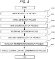
FIG. 3] FIG. 3 is a flowchart illustrating a processing flow of the road sign recognition device according to the first embodiment of the present invention. - [
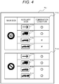
FIG. 4] FIG. 4 is a view illustrating an example of road sign information according to the first embodiment of the present invention. - [
FIG. 5] FIG. 5 is a view illustrating an example of a recognition result of an auxiliary sign according to the first embodiment of the present invention. - [
FIG. 6] FIG. 6 is a view illustrating an example of road sign information according to a second embodiment of the present invention. - [
FIG. 7] FIG. 7 is a flowchart illustrating a processing flow of a road sign recognition device according to a third embodiment of the present invention. - [
FIG. 8] FIG. 8 is a flowchart illustrating a processing flow of a road sign recognition device according to a fourth embodiment of the present invention. - [
FIG. 9] FIG. 9 is a view illustrating a scene for describing an operation of a road sign recognition device according to a fifth embodiment of the present invention. - [
FIG. 10] FIG. 10 is a flowchart illustrating a processing flow of the road sign recognition device according to the fifth embodiment of the present invention. - [
FIG. 11] FIG. 11 is a view illustrating an example of road sign information according to the fifth embodiment of the present invention. - [
FIG. 12] FIG. 12 is a functional block diagram illustrating a configuration of a road sign recognition device according to a sixth embodiment of the present invention. - [
FIG. 13] FIG. 13 is a view illustrating a scene for describing an operation of the road sign recognition device according to the sixth embodiment of the present invention. - [
FIG. 14] FIG. 14 is a flowchart illustrating a processing flow of the road sign recognition device according to the sixth embodiment of the present invention. - [
FIG. 15] FIG. 15 is a view illustrating an example of road sign information according to the sixth embodiment of the present invention. - [
FIG. 16] FIG. 16 is a view illustrating an example of a recognition result of an auxiliary sign according to the sixth embodiment of the present invention. - [
FIG. 17] FIG. 17 is a view illustrating a scene for describing an operation of a road sign recognition device according to a seventh embodiment of the present invention. - [
FIG. 18] FIG. 18 is a flowchart illustrating a processing flow of the road sign recognition device according to the seventh embodiment of the present invention. - [
FIG. 19] FIG. 19 is a view illustrating an example of road sign information according to the seventh embodiment of the present invention. - [
FIG. 20] FIG. 20 is a functional block diagram illustrating a configuration of a road sign recognition device according to an eighth embodiment of the present invention. - [
FIG. 21] FIG. 21 is a view illustrating a scene for describing an operation of the road sign recognition device according to the eighth embodiment of the present invention. - [
FIG. 22] FIG. 22 is a flowchart illustrating a processing flow of the road sign recognition device according to the eighth embodiment of the present invention. - [
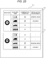
FIG. 23] FIG. 23 is a view illustrating an example of road sign information before rewriting according to the eighth embodiment of the present invention. - [
FIG. 24] FIG. 24 is a view illustrating an example of a recognition result of an auxiliary sign according to the eighth embodiment of the present invention. - [
FIG. 25] FIG. 25 is a view illustrating an example of road sign information after rewriting according to the eighth embodiment of the present invention. - Hereinafter, embodiments of the present invention will be described in detail.
-
FIG. 1 is a functional block diagram illustrating a configuration of a road sign recognition device according to a first embodiment of the present invention. As illustrated inFIG. 1 , a roadsign recognition device 10 of the present embodiment is connected to animaging device 20 and avehicle control device 30, and includes animage acquisition unit 101, a roadsign recognition unit 102, a road signdata recording unit 103, and a vehicle controlinformation determination unit 104. The roadsign recognition device 10 is configured using, for example, a computer having an arithmetic device such as a CPU and a storage device such as a ROM, a RAM, and a flash memory, and operates as each of the above functional blocks by executing a control program stored in the storage device with the arithmetic device. Note that some or all of functions of the roadsign recognition device 10 may be configured using hardware such as an FPGA. - The
imaging device 20 is a camera mounted on a vehicle, and captures the surroundings of the vehicle, for example, a scene in front of the vehicle. Hereinafter, the vehicle on which theimaging device 20 is mounted is referred to as a "host vehicle". Theimaging device 20 outputs a captured image to the roadsign recognition device 10 at a predetermined frame rate, for example. The image output from theimaging device 20 is input to theimage acquisition unit 101 in the roadsign recognition device 10. - The
image acquisition unit 101 controls an operation of theimaging device 20 to acquire the image captured by theimaging device 20 and outputs the image to the roadsign recognition unit 102. Theimage acquisition unit 101 calculates, for example, a camera control value to control the brightness at the time of imaging from an immediately previous image, and instructs theimaging device 20 by the next imaging. The camera control value corresponds to an exposure time of theimaging device 20, an analog gain value, an F-number of a lens, and the like. Theimage acquisition unit 101 can calculate the camera control value based on, for example, the brightness of a road surface or a sky area in the image. - The road
sign recognition unit 102 recognizes a road sign from the image acquired by theimage acquisition unit 101, and outputs the recognition result to the vehicle controlinformation determination unit 104. The roadsign recognition unit 102 can recognize various types of road signs such as a road sign in which a main sign and an auxiliary sign are combined. Examples of the main signs to be recognized by the roadsign recognition unit 102 include a main sign of a signboard type, a main sign of an electric light display type, a main sign of an internal illumination type illuminated by a backlight, and the like. In addition, examples of the auxiliary sign to be recognized by the roadsign recognition unit 102 include an auxiliary sign of a signboard type and an auxiliary sign of an electric light display type. Note that a road sign formed of only the main sign without being combined with any auxiliary sign may be included in a target to be recognized by the roadsign recognition unit 102, but a case where the roadsign recognition unit 102 recognizes a road sign in which a main sign and an auxiliary sign are combined will be described hereinafter. - When the road
sign recognition unit 102 recognizes a road sign from an image, various well-known processing methods can be used. For example, there is a method of identifying a candidate area including a circular object or a rectangular object in an image by performing Hough transform, maximally stable extremal regions (MSER), and the like, and then, performing a recognition process on the identified candidate area. As the recognition process, for example, a template matching process using a template image of a road sign to be recognized can be performed to acquire a type of road sign associated with the template image with the highest correlation can be acquired as a recognition result. In addition, a recognition score for each type of road sign may be acquired by a statistical method using machine learning based on a large number of images obtained by capturing road signs, and the type with the highest score value may be acquired as a recognition result. In addition, it is possible to recognize a road sign from an image using an arbitrary processing method as long as an appropriate recognition result can be obtained. - Here, an auxiliary sign is not installed alone as a road sign, the road
sign recognition unit 102 may detect the auxiliary sign after detecting a main sign. - Specifically, a candidate area including a rectangular object may be identified only for a peripheral part of an area recognized as the main sign in an image, and an auxiliary sign recognition process may be performed on the candidate area by a statistical method using a template matching process or machine learning.
- Note that when performing a road sign recognition process, the road
sign recognition unit 102 may refer to road sign information, which will be described later, stored in the road signdata recording unit 103 to limit a type of road sign to be recognized. Specifically, the number of template images used for template matching can be limited to perform the recognition process. - The road sign
data recording unit 103 stores road sign information about various road signs installed on a road on which the host vehicle travels. Examples of the road sign information include information indicating various combinations of main signs and auxiliary signs that can be obtained in road signs, information indicating the frequency of appearance for each combination, information indicating the likelihood of attachment of an auxiliary sign for each main sign, and the like. The road sign information stored in the road signdata recording unit 103 is referred to by the roadsign recognition unit 102 and the vehicle controlinformation determination unit 104, and is used in processes performed by these. - The vehicle control
information determination unit 104 determines vehicle control information used for controlling the host vehicle based on a road sign recognition result of the roadsign recognition unit 102 and the road sign information stored in the road signdata recording unit 103. Specifically, for example, the vehicle controlinformation determination unit 104 identifies a type of an auxiliary sign based on recognition results of a main sign and an auxiliary sign of the roadsign recognition unit 102 and the relationship between the main sign and the auxiliary sign represented by the road sign information stored in the road signdata recording unit 103, and determines the vehicle control information according to the type of the auxiliary sign. As a result, it is possible to accurately identify the type of the auxiliary sign and determine the vehicle control information. The vehicle control information determined by the vehicle controlinformation determination unit 104 is output from the roadsign recognition device 10 to thevehicle control device 30. Note that details of a method for determining the vehicle control information by the vehicle controlinformation determination unit 104 will be described later. - The
vehicle control device 30 performs the control of the host vehicle based on the vehicle control information output from the roadsign recognition device 10. For example, a regulation content applied to the host vehicle can be displayed on a display installed in the host vehicle to be presented to a driver, or to control a travel speed of the host vehicle. - Next, an operation of the road
sign recognition device 10 of the present embodiment described above will be described by taking an operation in a scene illustrated inFIG. 2 as an example.FIG. 2 illustrates the scene in which the host vehicle is a truck and a road sign in which a main sign and an auxiliary sign are combined is installed in front of the host vehicle. InFIG. 2 , a main sign T101 is a sign indicating that the maximum speed limit is 50 km/h, and an auxiliary sign T102 is a sign indicating that the truck is a regulation target vehicle. Hereinafter, a type of the main sign T101 will be referred to as a "maximum speed 50 km sign", and a type of the auxiliary sign T102 will be referred to as a "truck sign". It can be seen that the maximum speed of the host vehicle, which is the truck, is limited to 50 km/h with the combination of these signs. -
FIG. 3 is a flowchart illustrating a processing flow of the roadsign recognition device 10 according to the first embodiment of the present invention. The roadsign recognition device 10 of the present embodiment performs the processing illustrated in the flowchart ofFIG. 3 every predetermined processing cycle using an arithmetic device, for example, a CPU or the like. Hereinafter, a specific operation example of the roadsign recognition device 10 in the scene ofFIG. 2 will be described according to the flowchart ofFIG. 3 . - In Step S101, the
image acquisition unit 101 acquires an image obtained by capturing the surroundings of the host vehicle from theimaging device 20. Here, an image including an image of the main sign T101 and an image of the auxiliary sign T102 obtained by capturing the scene illustrated inFIG. 2 by theimaging device 20 is acquired as an image to be processed thereafter. - In Steps S102 to S105, the road
sign recognition unit 102 performs a process of recognizing a road sign from the image acquired in Step S101. In this process, a main sign recognition process is first performed in Steps S102 and S103, and then, an auxiliary sign recognition process is performed in Steps S104 and S105. - In Step S102, a circle detection process is performed. In this circle detection process, a circular area corresponding to a shape of a main sign is detected in the image acquired in Step S101, and this area is set as a candidate area for the main sign. As a result, the circular candidate area corresponding to the main sign T101 in
FIG. 2 is detected in the image. - In Step S103, the main sign recognition process is performed based on a result of the circle detection process in Step S102. In this main sign recognition process, the above-described recognition process is performed on an image area including the candidate area for the main sign detected in Step S102 to detect a main sign and identify its type. As a result, the main sign T101 of
FIG. 2 is detected in the image, and its type is identified as themaximum speed 50 km sign. - In Step S104, a rectangle detection process is performed. In this rectangle detection process, a rectangular area corresponding to a shape of an auxiliary sign is detected in an image area in a periphery of an area where the main sign has been detected in Step S103, for example, an image area in a predetermined range located below the area where the main sign has been detected, and this area is set as a candidate area for the auxiliary sign. As a result, a rectangular candidate area corresponding to the auxiliary sign T102 in
FIG. 2 is detected in the image. - In Step S105, the auxiliary sign recognition process is performed based on a result of the rectangle detection process in Step S104. In this auxiliary sign recognition process, the above-described recognition process is performed on an image area including the candidate area for the auxiliary sign detected in Step S104 to detect the auxiliary sign and calculate a recognition score of the auxiliary sign. The recognition score is information indicating the accuracy for each type of the detected auxiliary sign for the image recognition result, that is, the precision of recognition for each type of the auxiliary sign. As a result, the auxiliary sign T102 of
FIG. 2 is detected in the image, and the recognition score for each type is calculated. However, the type of the auxiliary sign T102 is not identified at this point in time. - In Step S106, the vehicle control
information determination unit 104 acquires road sign information based on the recognition result of Step S103 from the road signdata recording unit 103. In this process, the road sign information corresponding to the type of the main sign identified in Step S103 is read from the road sign information stored in the road signdata recording unit 103. -
FIG. 4 is a view illustrating an example of road sign information T111 stored in the road signdata recording unit 103 in the first embodiment of the present invention. In the road sign information T111 illustrated inFIG. 4 , information indicating a combination of a main sign and an auxiliary sign is described for each type regarding various types of main signs . Specifically, the road sign information T111 inFIG. 4 includes combination information T112 corresponding to themaximum speed 50 km sign and combination information T113 corresponding to a parking prohibition sign. In the rightmost column of these combination information T112 and T113, the possibility of combination for various types of auxiliary signs T114 to T117 is described. Note that the auxiliary sign T114 is a sign indicating a position where a regulation of a main sign starts, and the auxiliary signs T115 to T117 are signs indicating types of regulation target vehicles. Specifically, the auxiliary sign T115, the auxiliary sign T116, and the auxiliary sign T117 indicate that the regulation target vehicles are a truck, a car, and a towing vehicle, respectively. Hereinafter, the type of the auxiliary sign T114, the type of the auxiliary sign T116, and the type of the auxiliary sign T117 will be referred to as a "start sign", a "car sign", and a "towing vehicle sign", respectively. - In the road sign information T111 in
FIG. 4 , the combination information T112 indicates that themaximum speed 50 km sign is likely to be attached with the start sign and the truck sign, and is not attached with the car sign and the towing vehicle sign. On the other hand, the combination information T113 indicates that the parking prohibition sign is likely to be attached with each of the start sign, the truck sign, the car sign, and the towing vehicle sign. - Note that the road sign information T111 illustrated in
FIG. 4 is an example, and a content of the road sign information stored in the road signdata recording unit 103 is not limited thereto. For example, types of main signs and types of auxiliary signs described in the road sign information may be further increased as compared with the example ofFIG. 4 and stored in the road signdata recording unit 103. - In the following description, it is assumed that a recognition result that the type of the main sign T101 is the
maximum speed 50 km sign is obtained for the scene ofFIG. 2 as described above in the main sign recognition process in Step S103. Therefore, in a road sign information acquisition process in Step S106, the vehicle controlinformation determination unit 104 acquires the combination information T112 of the auxiliary sign for themaximum speed 50 km sign from the road sign information T111 stored in the road signdata recording unit 103. - Returning to the description of
FIG. 3 , the vehicle controlinformation determination unit 104 determines a control content of the host vehicle in Step S107 based on the recognition results of the main sign and the auxiliary sign respectively obtained in Steps S103 and S105 and the road sign information acquired in Step S106. In this process, a type of an auxiliary sign is identified by collating the recognition result of the auxiliary sign obtained in Step S105 with the road sign information acquired in Step S106. Then, a regulation content that applies to the host vehicle is determined based on the identified type of the auxiliary sign and the type of the main sign identified in Step S103, and accordingly, the control content of the host vehicle is determined. -
FIG. 5 is a view illustrating an example of a recognition result T121 of the auxiliary sign T102 obtained in Step S105 in the roadsign recognition device 10 of the present embodiment. In the recognition result T121 illustrated inFIG. 5 , the horizontal axis represents a type of an auxiliary sign, and the vertical axis represents a recognition score for each type. Here, the higher the recognition score is, the higher the accuracy of recognition is. The recognition result T121 ofFIG. 5 illustrates that recognition scores, which are higher in the order of the car sign, the truck sign, the start sign, and the towing vehicle sign, are obtained for the auxiliary sign T102. That is, as illustrated inFIG. 2 , the recognition score of the car sign is the highest for the auxiliary sign T102 which is actually the truck sign. - In a vehicle control content determination process in Step S107, the vehicle control
information determination unit 104 identifies a type of an auxiliary sign having the highest recognition score in the recognition result T121 as the type of the auxiliary sign T102 among types of auxiliary signs that satisfy combination conditions described in the combination information T112 acquired in Step S106. Specifically, the car sign having the highest recognition score in the recognition result T121 ofFIG. 5 has a combination condition of "x" in the combination information T112 ofFIG. 4 , which indicates that the car sign is not attached to themaximum speed 50 km sign. Therefore, it is determined that there is no possibility that the auxiliary sign T102 is the car sign, and the car sign is excluded from the type of the auxiliary sign T102. On the other hand, the truck sign having the second highest recognition score in the recognition result T121 has a combination condition of "o" in the combination information T112 inFIG. 4 , which indicates that the truck sign can be attached to themaximum speed 50 km sign. Therefore, the truck sign is identified as the type of the auxiliary sign T102. As a result, a correct recognition result is obtained for the auxiliary sign T102. - When the control content of the host vehicle has been determined in Step S107, the vehicle control
information determination unit 104 generates vehicle control information according to the control content and outputs the vehicle control information to thevehicle control device 30. Thereafter, the processing illustrated in the flowchart ofFIG. 3 is ended. - As described above, in the road
sign recognition device 10 of the present embodiment, the type of the auxiliary sign, which is hardly recognized only by image recognition due to the small pattern or characters, is identified by using the other information such as the combination information with the main sign. Therefore, misrecognition can be reduced and recognition performance can be improved. - In addition, the combination information used when identifying the type of the auxiliary sign is selected from the recognition result of the main sign, which is easily recognized due to the large pattern or characters. Therefore, the optimum combination information can be correctly acquired from the road sign information stored in the road sign
data recording unit 103. - According to the first embodiment of the present invention described above, the following operational effects are achieved.
- (1) The road
sign recognition device 10 includes: theimage acquisition unit 101 that acquires an image; the roadsign recognition unit 102 that recognizes a road sign from the image acquired by theimage acquisition unit 101; the road signdata recording unit 103 that stores the road sign information T111 about a combination of a plurality of road signs; and the vehicle controlinformation determination unit 104 that determines vehicle control information used for controlling the host vehicle. The vehicle controlinformation determination unit 104 determines the vehicle control information based on the road sign recognition result of the roadsign recognition unit 102 and the road sign information T111 stored in the road sign data recording unit 103 (Step S107). In this manner, the control content of the host vehicle can be correctly determined from the road sign recognition result. - (2) The road sign information T111 includes the combination information T112 and T113 which are pieces of information about combinations of main signs and auxiliary signs. In this manner, it is possible to reliably identify the auxiliary sign used in combination with the main sign from the recognition result of the main sign and determine the control content of the host vehicle.
- (3) The vehicle control
information determination unit 104 acquires the combination information T112 corresponding to the main sign T101 from the road signdata recording unit 103 based on the recognition result of the main sign T101 of the road sign recognition unit 102 (Step S106) . In Step S107, the type of the auxiliary sign T102 used for determining the vehicle control information is identified based on the combination information T112 acquired in Step S106 and the recognition result of the auxiliary sign T102 of the roadsign recognition unit 102 in Step S105. In this manner, even for the auxiliary sign, which is hardly recognized only by image recognition due to the small pattern or characters, the type of the auxiliary sign can be accurately identified and used for determining the vehicle control information. - Next, a second embodiment of the present invention will be described. The description has been given in the first embodiment described above regarding the example in which the combination information in the road sign information stored in the road sign
data recording unit 103 has two values that represent the possibility of the combination with the auxiliary sign for each type of the main sign. On the other hand, in the second embodiment of the present invention, an example in which combination information in road sign information stored in the road signdata recording unit 103 is expressed as continuous values that represent the frequency of appearance with auxiliary signs for each type of main signs will be described hereinafter. - Note that a configuration of the road
sign recognition device 10 according to the present embodiment is the same as that described with reference toFIG. 1 in the first embodiment, the description thereof will be omitted hereinafter. In addition, a processing flow of the roadsign recognition device 10 according to the present embodiment is the same as that described with reference toFIG. 3 in the first embodiment, and only a part of a processing content of Step S107 is different. Therefore, a description of a part overlapping with the first embodiment in the processing performed by the roadsign recognition device 10 according to the present embodiment will be omitted hereinafter. -
FIG. 6 is a view illustrating an example of road sign information T131 stored in the road signdata recording unit 103 in the second embodiment of the present invention. In combination information T132 and T133 in the road sign information T131 inFIG. 6 , the content described in the rightmost column is different as compared with the combination information T112 and T113 in the road sign information T111 of the first embodiment illustrated inFIG. 4 . Specifically, in the combination information T132 and T133, not the possibility of the combination for each type of the auxiliary sign as illustrated inFIG. 4 but the frequency of appearance for each type of the auxiliary sign is described in the rightmost column. That is, the larger a value of the frequency of appearance is, the higher the possibility that the auxiliary sign is attached to the corresponding main sign is. - When the road sign information T131 illustrated in
FIG. 6 is used, the vehicle controlinformation determination unit 104 acquires the combination information T132 of the auxiliary sign related to themaximum speed 50 km sign from the road sign information T131 in Step S106 ofFIG. 3 . In the subsequent Step S107, the vehicle controlinformation determination unit 104 calculates a product of a recognition score value in the recognition result T121 ofFIG. 5 obtained in Step S105 and a value of the frequency of appearance in the combination information T132 acquired in Step S106 for each type of auxiliary signs. Then, a type of an auxiliary sign having the highest calculated product value is identified as the type of the auxiliary sign T102. Specifically, in the case of a car sign, for example, the recognition score is 0.5, and the frequency of appearance is 0.1. Thus, the value of the product of these is calculated as 0.05. As the same calculation is performed, product values of a truck sign, a start sign, and a towing vehicle sign are calculated as 0.14, 0.05, and 0.00, respectively. Therefore, the truck sign having the highest product value is identified as the type of the auxiliary sign T102. As a result, a correct recognition result is obtained for the auxiliary sign T102. - As described above, the combination information in the road sign information stored in the road sign
data recording unit 103 is expressed by continuous values in the roadsign recognition device 10 of the present embodiment so that the frequency for each combination of the main sign and auxiliary sign can be set in detail. Therefore, it is possible to identify the type of the auxiliary sign by more deeply reflecting an installation condition of a road sign in the actual environment. - According to the second embodiment of the present invention described above, the following operational effect in (4) is further achieved in addition to the respective operational effects of (1) to (3) described in the first embodiment.
- (4) The combination information T132 and T133 include information on the frequency of appearance for each combination of the main sign and the auxiliary sign. In this manner, an auxiliary sign used in combination with a main sign can be more accurately identified from a recognition result of the main sign.
- Next, a third embodiment of the present invention will be described. In each of the first and second embodiments described above, the description has been given regarding the example in which the type of the auxiliary sign is identified by using the road sign information stored in the road sign
data recording unit 103 regardless of the recognition result of the auxiliary sign of the roadsign recognition unit 102. On the other hand, in the third embodiment of the present invention, an example of switching whether or not to use road sign information stored in the road signdata recording unit 103 depending on recognition precision of an auxiliary sign of the roadsign recognition unit 102 will be described hereinafter. - Note that a configuration of the road
sign recognition device 10 according to the present embodiment is the same as that described with reference toFIG. 1 in the first embodiment, the description thereof will be omitted hereinafter. -
FIG. 7 is a flowchart illustrating a processing flow of the roadsign recognition device 10 according to the third embodiment of the present invention. The roadsign recognition device 10 of the present embodiment performs the processing illustrated in the flowchart ofFIG. 7 every predetermined processing cycle using an arithmetic device, for example, a CPU or the like. - In Steps S111 to S115, the
image acquisition unit 101 and the roadsign recognition unit 102 perform the same processes as those in Steps S101 to S105 ofFIG. 3 . - In Step S116, it is determined whether or not the accuracy of a recognition result of an auxiliary sign obtained by the auxiliary sign recognition process of Step S115, that is, the recognition precision of the auxiliary sign is equal to or higher than a predetermined value. As a result, the processing proceeds to Step S117 if the accuracy of the recognition result of the auxiliary sign is lower than the predetermined value.
- In this case, the same processes as those in Steps S106 and S107 of
FIG. 3 are performed in Steps S117 and S118, respectively. - On the other hand, if it is determined in Step S116 that the accuracy of the recognition result of the auxiliary sign is equal to or higher than the predetermined value, the processing proceeds to Step S118 without performing the process of Step S117. In this case, combination information of an auxiliary sign corresponding to a type of a main sign is not acquired from the road sign
data recording unit 103 since the process of Step S117 is not executed. Therefore, in Step S118, the vehicle controlinformation determination unit 104 does not use the combination information stored in the road signdata recording unit 103 and identifies a type of an auxiliary sign based only on a recognition result of the auxiliary sign obtained in Step S115. Then, a regulation content that applies to a host vehicle is determined based on the identified type of the auxiliary sign and the type of the main sign identified in Step S113, and accordingly, a control content of the host vehicle is determined. - Specifically, for example, a case where a threshold for the accuracy of the recognition result of the auxiliary sign used for the determination in Step S116 is 0.6 and a recognition score for any type of the auxiliary sign is 0.9 in the auxiliary sign recognition process in Step S115 is considered. In this case, since an affirmative determination is made in Step S116, the vehicle control
information determination unit 104 does not perform the road sign information acquisition process in Step S117, and identifies the type of the auxiliary sign only based on the recognition result of the auxiliary sign obtained in Step S115. That is, a type of a road sign used for vehicle control is identified using only the recognition result of the main sign obtained by the main sign recognition process in Step S113 and the recognition result of the auxiliary sign obtained by the auxiliary sign recognition process in Step S115. - On the other hand, when the highest recognition score in the auxiliary sign recognition process in Step S115 is a value lower than the threshold, for example, 0.3, s negative determination is made in Step S116, and thus, the vehicle control
information determination unit 104 performs the road sign information acquisition process in Step S117. Then, the type of the auxiliary sign is identified based on the recognition result of the auxiliary sign obtained in Step S115 and the combination information acquired in Step S117. That is, the type of the road sign to be used for vehicle control is identified by further using combination information in the road sign information stored in the road signdata recording unit 103 in addition to the recognition result of the main sign obtained by the main sign recognition process in Step S113 and the recognition result of the auxiliary sign obtained by the auxiliary sign recognition process in Step S115. - As described above, the type of the road sign used for vehicle control is identified only using the result of image recognition when the accuracy of image recognition for the auxiliary sign is high and it can be determined that the type of the auxiliary sign can be correctly recognized only by image recognition in the road
sign recognition device 10 of the present embodiment. Therefore, the road sign information acquisition process for acquiring the combination information about the combination of the main sign and the auxiliary sign can be omitted, and the number of accesses to the road signdata recording unit 103 can be reduced. Therefore, the processing time can be shortened. - According to the third embodiment of the present invention described above, the following operational effect in (5) is further achieved in addition to the respective operational effects of (1) to (4) described in the first and second embodiments.
- (5) When the recognition precision of the auxiliary sign of the road
sign recognition unit 102 is equal to or higher than the predetermined value (Step S116: YES), the vehicle controlinformation determination unit 104 identifies the type of the auxiliary sign used for determining the vehicle control information without using the combination information stored in the road sign data recording unit 103 (Step S118) . In this manner, it is possible to reduce the number of accesses to the road signdata recording unit 103 and shorten the processing time. - Next, a fourth embodiment of the present invention will be described. In the third embodiment described above, the description has been given regarding the example of switching whether or not to use the road sign information stored in the road sign
data recording unit 103 for identifying the type of the auxiliary sign depending on the recognition precision of the auxiliary sign of the roadsign recognition unit 102. On the other hand, in the fourth embodiment of the present invention, an example of switching the priority of using road sign information stored in the road signdata recording unit 103 depending on recognition precision of an auxiliary sign of the roadsign recognition unit 102 will be described hereinafter. - Note that a configuration of the road
sign recognition device 10 according to the present embodiment is the same as that described with reference toFIG. 1 in the first embodiment, the description thereof will be omitted hereinafter. -
FIG. 8 is a flowchart illustrating a processing flow of the roadsign recognition device 10 according to the fourth embodiment of the present invention. The roadsign recognition device 10 of the present embodiment performs the processing illustrated in the flowchart ofFIG. 8 every predetermined processing cycle using an arithmetic device, for example, a CPU or the like. - In Steps S121 to S126, the
image acquisition unit 101, the roadsign recognition unit 102, and the vehicle controlinformation determination unit 104 perform the same processes as those in Steps S101 to S106 ofFIG. 3 . - In Step S127, it is determined whether or not the accuracy of a recognition result of an auxiliary sign obtained by the auxiliary sign recognition process of Step S125, that is, the recognition precision of the auxiliary sign is equal to or higher than a predetermined value. As a result, the processing proceeds to Step S129 if the accuracy of the recognition result of the auxiliary sign is equal to or higher than the predetermined value. In this case, the same process as that in Step S107 of
FIG. 3 is performed in Step S129 to identify a type of the auxiliary sign and determine a control content of a host vehicle. - On the other hand, the processing proceeds to Step S128 if it is determined in Step S127 that the accuracy of the recognition result of the auxiliary sign is lower than the predetermined value. In Step S128, the vehicle control
information determination unit 104 performs a road sign information prioritization process which is a process for prioritizing the road sign information acquired from the road signdata recording unit 103 in Step S126 over the recognition result of the auxiliary sign. In this process, for example, the combination information for each type of auxiliary signs in the acquired road sign information is amplified to prioritize the road sign information over the recognition result of the auxiliary sign. Specifically, for example, a case where the combination information T132 is read from the road signdata recording unit 103 from the road sign information T131 ofFIG. 6 described in the second embodiment is considered. In this case, the combination information T132 can be amplified by adding or multiplying a predetermined value to a value of the frequency of appearance for each type of auxiliary signs described in the combination information T132. Note that a content of the road sign information prioritization process is not limited thereto if the road sign information can be prioritized over the recognition result of the auxiliary sign. - After performing the road sign information prioritization process in Step S128, the vehicle control
information determination unit 104 proceeds to Step S129 and performs the process of Step S129 using the amplified combination information. As a result, the type of the auxiliary sign is identified by using the road sign information acquired from the road signdata recording unit 103 in Step S126 with a priority over the recognition result of the auxiliary sign obtained in Step S125. Then, a regulation content that applies to the host vehicle is determined based on the identified type of the auxiliary sign and the type of the main sign identified in Step S123, and accordingly, the control content of the host vehicle is determined. - As described above, in the road
sign recognition device 10 of the present embodiment, the type of the road sign used for vehicle control is identified by preferentially using the road sign information about the combination of the main sign and auxiliary sign in a scene where the accuracy of image recognition for the auxiliary sign is low, for example, a case where the auxiliary sign is located in the distance or the like. Therefore, even in a scene where the accuracy of image recognition for the auxiliary sign is low, the auxiliary sign can be recognized with high accuracy and vehicle control can be performed. - Note that the road sign information is acquired from the road sign
data recording unit 103 and used to identify the type of the auxiliary sign even when the accuracy of the recognition result of the auxiliary sign is equal to or higher than the predetermined value in the flowchart ofFIG. 8 . However, as described in the third embodiment, the type of the auxiliary sign may be identified only based on the recognition result of the auxiliary sign obtained in Step S125 without using the road sign information stored in the road signdata recording unit 103 when the accuracy of the recognition result of the auxiliary sign is equal to or higher than the predetermined value. For example, the type of the auxiliary sign can be identified only based on the recognition result of the auxiliary sign by exchanging the order of Steps S126 and S127 inFIG. 8 and not performing the processes of Steps S126 and S128 when it is determined in Step S127 that the accuracy of the recognition result of the auxiliary sign is equal to or higher than the predetermined value. Alternatively, two types of thresholds may be used such that a case where the road sign information is not used, a case where the road sign information acquired from the road signdata recording unit 103 is used as it is, and a case where the acquired road sign information is used with a priority over the recognition result of the auxiliary sign may be used properly in accordance with the accuracy of the recognition result of the auxiliary sign. - According to the fourth embodiment of the present invention described above, the following operational effect in (6) is further achieved in addition to the respective operational effects of (1) to (5) described in the first to third embodiments.
- (6) When the recognition precision of the auxiliary sign of the road
sign recognition unit 102 is lower than the predetermined value (Step S127: NO), the vehicle controlinformation determination unit 104 identifies the type of the auxiliary sign used for determining the vehicle control information by using the combination information acquired from the road signdata recording unit 103 in Step S126 with a priority over the recognition result of the auxiliary sign of the road sign recognition unit 102 (Step S129) . In this manner, the type of the auxiliary sign used for determining the vehicle control information can be accurately identified even when the recognition precision of the auxiliary sign is low. - Next, a fifth embodiment of the present invention will be described. In the present embodiment, an example of performing auxiliary sign recognition in consideration of the likelihood of attachment of an auxiliary sign with respect to a main sign will be described hereinafter.
- Note that a configuration of the road
sign recognition device 10 according to the present embodiment is the same as that described with reference toFIG. 1 in the first embodiment, the description thereof will be omitted hereinafter. - An operation of the road
sign recognition device 10 of the present embodiment will be described by taking an operation in a scene illustrated inFIG. 9 as an example.FIG. 9 illustrates a scene in which a host vehicle is a truck, a road sign in which a main sign and an auxiliary sign are combined is installed in front of the host vehicle, and a large number of trees are installed along a road. InFIG. 9 , a main sign T141 and an auxiliary sign T142 correspond to amaximum speed 50 km sign and a truck sign, respectively, similarly to the main sign T101 and the auxiliary sign T102 inFIG. 2 . -
FIG. 10 is a flowchart illustrating a processing flow of the roadsign recognition device 10 according to the fifth embodiment of the present invention. The roadsign recognition device 10 of the present embodiment performs the processing illustrated in the flowchart ofFIG. 10 every predetermined processing cycle using an arithmetic device, for example, a CPU or the like. Hereinafter, a specific operation example of the roadsign recognition device 10 in the scene ofFIG. 9 will be described according to the flowchart ofFIG. 10 . - In Step S121, the
image acquisition unit 101 acquires an image obtained by capturing the surroundings of the host vehicle from theimaging device 20. Here, an image including an image of the main sign T141 and an image of the auxiliary sign T142 obtained by capturing the scene illustrated inFIG. 9 by theimaging device 20 is acquired as an image to be processed thereafter. - In Steps S122 and S123, the road
sign recognition unit 102 performs a process of recognizing a main sign from the image acquired in Step S121. Specifically, in Step S122, a circular area corresponding to a shape of the main sign is detected in the image acquired in Step S121, and a circle detection process is performed using this area as a candidate area for the main sign, which is similar to Step S102 inFIG. 3 . In the subsequent Step S123, a main sign recognition process is performed on an image area including the candidate area for the main sign detected by the circle detection process in Step S122 to detect the main sign and identify its type, which is similar to Step S103 inFIG. 3 . - Note that the following description will be given assuming that the main sign T141 in
FIG. 9 is detected in the image, and its type is identified as themaximum speed 50 km sign, and partial areas T143 to T145 of trees installed along the road are misrecognized as the main sign (hereinafter referred to as the "maximum speed 100 km sign") indicating that a maximum speed limit is 100 km/h in the processes of Steps S122 and S123. - In Step S124, the vehicle control
information determination unit 104 acquires road sign information based on the recognition result of Step S123 from the road signdata recording unit 103. In this process, the road sign information corresponding to the type of the main sign identified in Step S123 is read from the road sign information stored in the road signdata recording unit 103. -
FIG. 11 is a view illustrating an example of road sign information T151 stored in the road signdata recording unit 103 in the fifth embodiment of the present invention. The road sign information T151 illustrated inFIG. 11 includes the combination information T152 corresponding to themaximum speed 50 km sign and the combination information T153 corresponding to themaximum speed 100 km sign, and the frequency of appearance for each type of auxiliary signs is described in the rightmost column in these combination information T152 and T153. - Further, the combination information T152 and T153 also describe the degree of attachment of an auxiliary sign indicating the likelihood of attachment of the auxiliary sign for each of main signs. The higher a value of the degree of attachment of the auxiliary sign is, the higher the possibility that the auxiliary sign is attached is. In the example of
FIG. 11 , the value of the degree of attachment of the auxiliary sign in the combination information T152 is 8 and the value of the degree of attachment of the auxiliary sign in the combination information T153 is 1, and thus, this indicates that themaximum speed 50 km sign is more likely to be attached with the auxiliary sign than themaximum speed 100 km sign. - In the scene of
FIG. 9 , as described above, in Step S123, the recognition result that the type of the main sign T141 is themaximum speed 50 km sign is obtained, and the recognition result as themaximum speed 100 km sign is obtained due to misrecognition of the types of the partial areas T143 to T145 of the tree. Therefore, in a road sign information acquisition process in Step S124, the vehicle controlinformation determination unit 104 acquires the combination information T152 of the auxiliary sign for themaximum speed 50 km sign and the combination information T153 of the auxiliary sign for themaximum speed 100 km sign from the road sign information T151 stored in the road signdata recording unit 103. - Returning to the description of
FIG. 10 , in Step S125, an auxiliary sign recognition candidate area is determined in the image based on the road sign information acquired in Step S124. In this process, a value of the degree of attachment of the auxiliary sign in the combination information of the road sign information acquired in Step S124 is referred to, and main signs are selected within a predetermined upper limit number in order from one with the highest value of the degree of attachment of the auxiliary sign among the plurality of main signs recognized in Step S123. Then, a predetermined image area in a periphery of each of the selected main signs is set as the auxiliary sign recognition candidate area. As a result, the auxiliary sign recognition process is performed in the roadsign recognition unit 102 while prioritizing the periphery of the main sign to which the auxiliary sign is highly likely to be attached in the acquired combination information among the plurality of main signs recognized from the image. - Note that the upper limit number of the main signs selected in Step S125 can be determined in advance by referring to, for example, the processing time required for the auxiliary sign recognition process and the processing time assigned to the processing of the flowchart of
FIG. 10 and the like. Alternatively, the upper limit number of the selected main signs may be set based on a recognition score at the time of recognizing each main sign, the number of the recognized main signs, and the like. - In the road sign information T151 of
FIG. 11 , the value of the degree of attachment of the auxiliary sign in the combination information T152 is 8, and the value of the degree of attachment of the auxiliary sign in the combination information T153 is 1 as described above. Here, assuming that the upper limit number of the main signs selected in Step S125 is 1, only the main sign T141 corresponding to the combination information T152 is selected, and the partial areas T143 to T145 of the tree misrecognized as the main signs are not selected, in the scene ofFIG. 9 . Then, a predetermined area in a periphery of the selected main sign T141, for example, an area in a predetermined range located immediately below the main sign T141 is set as the auxiliary sign recognition candidate area. - In Step S126, the processes of Steps S127 and S128 are performed for each of the recognition candidate areas set in Step S125 to perform the process of recognizing the auxiliary sign. Specifically, in Step S127, a rectangular area corresponding to a shape of the auxiliary sign is detected in each recognition candidate area, and a rectangle detection process is performed using this area as a candidate area for the auxiliary sign.
- In the subsequent Step S128, the auxiliary sign recognition process is performed on an image area including the candidate area for the auxiliary sign detected in the rectangle detection process of Step S127 to detect the auxiliary sign and calculate a recognition score of the auxiliary sign. As a result, the auxiliary sign T142 is detected in the image for the auxiliary sign recognition candidate area set in the periphery of the main sign T141 in
FIG. 9 , and the recognition score for each type is calculated. However, the type of the auxiliary sign T142 is not identified at this point in time. - When the processes of Steps S127 and S128 have been performed for all the recognition candidate areas set in Step S125, the processing proceeds to Step S129. The vehicle control
information determination unit 104 determines a control content of the host vehicle in Step S129 based on the recognition results of the main sign and the auxiliary sign respectively obtained in Steps S123 and S128 and the road sign information acquired in Step S124. That is, as in each of the above-described embodiments, the type of the auxiliary sign is identified by collating the recognition result of the auxiliary sign obtained in Step S128 with the road sign information acquired in Step S124. Then, a regulation content that applies to the host vehicle is determined based on the identified type of the auxiliary sign and the type of the main sign identified in Step S123, and accordingly, the control content of the host vehicle is determined. - As described above, the auxiliary sign recognition process can be preferentially performed in the area where the possibility that the auxiliary sign is installed is high in the road
sign recognition device 10 of the present embodiment. Therefore, even when a plurality of candidate areas for which the auxiliary sign recognition process needs to be performed from the recognition result of the main sign appear and it is difficult to perform the recognition process for all the candidate areas due to restrictions in the processing time, it is possible to perform the recognition process while prioritizing the area where the auxiliary sign is highly likely to appear and to recognize the auxiliary sign with high precision. - According to the fifth embodiment of the present invention described above, the following operational effect in (7) is further achieved in addition to the respective operational effects of (1) to (6) described in the first to fourth embodiments.
- (7) The combination information T152 and T153 include information on the likelihood of attachment of the auxiliary sign for each of the main signs. When the plurality of main signs are recognized from the image, the road
sign recognition unit 102 performs the auxiliary sign recognition process while prioritizing the area in the periphery of the main sign T141 to which the auxiliary sign is highly likely to be attached in the combination information T152 and T153 among the plurality of main signs (Steps S125 to S128). In this manner, the auxiliary signs can be recognized with high precision even if the plurality of main signs are erroneously recognized from the image. - Next, a sixth embodiment of the present invention will be described.
FIG. 12 is a functional block diagram illustrating a configuration of a road sign recognition device according to the sixth embodiment of the present invention. - As illustrated in
FIG. 12 , a roadsign recognition device 10A of the present embodiment is connected to theimaging device 20 and thevehicle control device 30, which is similar to the roadsign recognition device 10 according to the first embodiment described with reference toFIG. 1 . The roadsign recognition device 10A of the present embodiment includes animage acquisition unit 201, a roadsign recognition unit 202, a road signdata recording unit 203, a vehicle controlinformation determination unit 204, and a travelenvironment acquisition unit 205. The roadsign recognition device 10A is configured using, for example, a computer having an arithmetic device such as a CPU and a storage device such as a ROM, a RAM, and a flash memory, and operates as each of the above functional blocks by executing a control program stored in the storage device with the arithmetic device. - Note that some or all of functions of the road
sign recognition device 10A may be configured using hardware such as an FPGA. - The
image acquisition unit 201 controls an operation of theimaging device 20 to acquire an image captured by theimaging device 20 and output the image to the roadsign recognition unit 202, which is similar to theimage acquisition unit 101 ofFIG. 1 . - The road
sign recognition unit 202 recognizes a road sign from the image acquired by theimage acquisition unit 201, and outputs the recognition result to the vehicle controlinformation determination unit 204, which is similar to the roadsign recognition unit 102 inFIG. 1 . - The road sign
data recording unit 203 stores road sign information about various road signs installed on a road on which the host vehicle travels. Examples of the road sign information include information indicating various combinations of main signs and auxiliary signs that can be obtained in road signs, information indicating the frequency of appearance for each combination, information indicating the likelihood of attachment of an auxiliary sign for each main sign, and the like as described in each of the first to fifth embodiments. In addition, the road sign information used in the present embodiment includes information on a traveling environment for each road sign. This information represents characteristics of a road where the possibility that a road sign is installed is high for each type of the road sign, and is expressed by a road type, for example, a highway, an urban area, or the like. This information is determined, for example, based on installation standards of road signs for each country or region and the number of installations. Alternatively, road sign information of a plurality of countries or regions may be stored in the road signdata recording unit 203 together with the information on the travel environment for each road sign. - The travel
environment acquisition unit 205 acquires travel environment information around a host vehicle. For example, information on a type of a road on which the host vehicle is traveling and a country or region on which the host vehicle is traveling is acquired as the travel environment information around the host vehicle. Then, the acquired travel environment information is output to the vehicle controlinformation determination unit 204. The travelenvironment acquisition unit 205 is connected to, for example, a car navigation system (not illustrated), and the travel environment information can be acquired from this car navigation system. The car navigation system can identify the travel environment information around the host vehicle by acquiring position information of the host vehicle based on well-known positioning information such as a global positioning system (GPS) signal and referring to map information stored in advance. Alternatively, the travel environment information may be acquired from the outside of the host vehicle by wireless communication. - The vehicle control
information determination unit 204 determines vehicle control information used for controlling the host vehicle based on a road sign recognition result of the roadsign recognition unit 102, the travel environment information acquired by the travelenvironment acquisition unit 205, and the road sign information stored in the road signdata recording unit 203. - Specifically, for example, the vehicle control
information determination unit 204 identifies road sign information corresponding to the travel environment of the host vehicle from the road sign information stored in the road signdata recording unit 203 based on the travel environment information acquired by the travelenvironment acquisition unit 205. Then, a type of an auxiliary sign is identified based on recognition results of a main sign and an auxiliary sign of the roadsign recognition unit 102 and the relationship between the main sign and the auxiliary sign represented by the road sign information corresponding to the travel environment of the host vehicle, and vehicle control information is determined according to the type of the auxiliary sign, which is similar to the vehicle controlinformation determination unit 104 ofFIG. 1 . As a result, it is possible to accurately identify the type of the auxiliary sign and determine the vehicle control information in consideration of the traveling environment of the host vehicle. The vehicle control information determined by the vehicle controlinformation determination unit 204 is output from the roadsign recognition device 10A to thevehicle control device 30. - Next, an operation of the road
sign recognition device 10A of the present embodiment described above will be described by taking an operation in a scene illustrated inFIG. 13 as an example.FIG. 13 illustrates a scene in which the host vehicle is traveling on a general road and a road sign in which a main sign and an auxiliary sign are combined is installed in front of the host vehicle. InFIG. 13 , a main sign T201 is the above-describedmaximum speed 50 km sign, and an auxiliary sign T202 is the above-described start sign. It can be seen that the combination of these signs limits the maximum speed of the host vehicle to 50 km/h from an installation point of the road sign in which the main sign T201 and the auxiliary sign T202 are combined. -
FIG. 14 is a flowchart illustrating a processing flow of the roadsign recognition device 10A according to the sixth embodiment of the present invention. The roadsign recognition device 10A of the present embodiment performs the processing illustrated in the flowchart ofFIG. 14 every predetermined processing cycle using an arithmetic device, for example, a CPU or the like. Hereinafter, a specific operation example of the roadsign recognition device 10A in the scene ofFIG. 13 will be described according to the flowchart ofFIG. 14 . - In Step S201, the
image acquisition unit 201 acquires an image obtained by capturing the surroundings of the host vehicle from theimaging device 20. Here, an image including an image of the main sign T201 and an image of the auxiliary sign T202 obtained by capturing the scene illustrated inFIG. 13 by theimaging device 20 is acquired as an image to be processed thereafter. - In Steps S202 to S205, the road
sign recognition unit 202 performs the same processes as those in Steps S101 to S105 ofFIG. 3 . As a result, the main sign T201 and the auxiliary sign T202 inFIG. 13 are detected in the image, a type of the main sign T201 is identified as themaximum speed 50 km sign, and a recognition score of the auxiliary sign T202 is calculated for each type. - In Step S206, the travel
environment acquisition unit 205 acquires the above-described information corresponding to the position of the host vehicle as the travel environment information around the host vehicle. Here, for example, the information indicating that the type of the road on which the host vehicle is traveling is the general road is acquired as the travel environment information around the host vehicle. - In Step S207, the vehicle control
information determination unit 204 acquires road sign information based on the recognition result of Step S203 from the road signdata recording unit 203. In this process, the road sign information corresponding to the type of the main sign identified in Step S203 is read from the road sign information stored in the road signdata recording unit 203. -
FIG. 15 is a view illustrating an example of road sign information T211 stored in the road signdata recording unit 203 in the sixth embodiment of the present invention. In the road sign information T211 illustrated inFIG. 15 includes combination information T212 corresponding to themaximum speed 50 km sign and combination information T213 corresponding to amaximum speed 100 km sign, and the possibility of the combination for each auxiliary sign is described in these combination information T212 and T213 similarly toFIG. 4 . - Further, types of roads on which each auxiliary sign is likely to be installed are also described in the combination information T212 and T213 as an installation environment for each auxiliary sign. In the road sign information T211 in
FIG. 15 , the combination information T212 indicates that themaximum speed 50 km sign is likely to be attached with the start sign on the general road and attached with a truck sign on the highway, and is not attached with a car sign or a towing vehicle sign. On the other hand, the combination information T213 indicates that themaximum speed 100 km sign is likely to be attached with the car sign on the general road and attached with the towing vehicle sign on the highway, and is not attached with the start sign and the truck sign. - In the following description, it is assumed that a recognition result that the type of the main sign T201 is the
maximum speed 50 km sign is obtained for the scene ofFIG. 13 as described above in a main sign recognition process in Step S203. Therefore, in a road sign information acquisition process in Step S207, the vehicle controlinformation determination unit 204 acquires the combination information T212 of the auxiliary sign for themaximum speed 50 km sign from the road sign information T211 stored in the road signdata recording unit 203. - Returning to the description of
FIG. 14 , the vehicle controlinformation determination unit 204 determines a control content of the host vehicle in Step S208 based on the recognition results of the main sign and the auxiliary sign obtained in Steps S203 and S205, respectively, the travel environment information acquired in Step S206, and the road sign information acquired in Step S207. In this process, a type of an auxiliary sign is identified by collating the recognition result of the auxiliary sign obtained in Step S205 and the travel environment information acquired in Step S206 with the road sign information acquired in Step S207. Then, a regulation content that applies to the host vehicle is determined based on the identified type of the auxiliary sign and the type of the main sign identified in Step S203, and accordingly, the control content of the host vehicle is determined. -
FIG. 16 is a view illustrating an example of a recognition result T221 of the auxiliary sign T202 obtained in Step S205 in the roadsign recognition device 10A of the present embodiment. In the recognition result T221 illustrated inFIG. 16 , the horizontal axis represents a type of an auxiliary sign, and the vertical axis represents a recognition score for each type. Here, the higher the recognition score is, the higher the accuracy of recognition is. The recognition result T221 ofFIG. 16 illustrates that recognition scores, which are higher in the order of the truck sign, the start sign, the car sign, and the towing vehicle sign, are obtained for the auxiliary sign T202. That is, as illustrated inFIG. 13 , the recognition score of the truck sign is the highest for the auxiliary sign T202 which is actually the start sign. - In a vehicle control content determination process of Step S208, the vehicle control
information determination unit 204 identifies a combination condition corresponding to the travel environment of the host vehicle from the combination information T212 acquired in Step S207 based on the travel environment information acquired in Step S206, and identifies a type of an auxiliary sign having the highest recognition score in the recognition result T221 as the type of the auxiliary sign T202 from among types of auxiliary signs that satisfy the combination condition. Specifically, the truck sign having the highest recognition score in the recognition result T221 inFIG. 16 has a combination condition of "o" for the highway in the combination information T212 inFIG. 15 , which indicates that the truck sign is not attached to themaximum speed 50 km sign on the general road indicated by the acquired travel environment information. Therefore, it is determined that there is no possibility that the auxiliary sign T202 is the truck sign, and the truck sign is excluded from the type of the auxiliary sign T202. On the other hand, the start sign having the second highest recognition score in the recognition result T221 has a combination condition is "o" for the general road in the combination information T212 inFIG. 15 , which indicates that the start sign can be attached to themaximum speed 50 km sign on the general road indicated by the acquired travel environment information. Therefore, the start sign is identified as the type of the auxiliary sign T202. As a result, a correct recognition result is obtained for the auxiliary sign T202. - When the control content of the host vehicle has been determined in Step S208, the vehicle control
information determination unit 204 generates vehicle control information according to the control content and outputs the vehicle control information to thevehicle control device 30. Thereafter, the processing illustrated in the flowchart ofFIG. 14 is ended. - As described above, the type of the road on which the host vehicle is traveling is acquired as the travel environment information, and is used to identify the type of the auxiliary sign in the road
sign recognition device 10A of the present embodiment. Therefore, it is possible to identify the type of the auxiliary sign in consideration of the traveling environment of the host vehicle, and the recognition performance can be further improved. - Note that the circle detection process, the main sign recognition process, the rectangle detection process, the auxiliary sign recognition process, the travel environment information acquisition process, and the road sign information acquisition process are sequentially performed in Steps S202 to S207 in the flowchart of
FIG. 14 . However, the order of execution of these processes may be changed. For example, the processing order may be changed such that the travel environment information acquisition process in Step S206 and the road sign information acquisition process in Step S207 are performed after performing the circle detection process in Step S202 and the main sign recognition process in Step S203, and then, the rectangle detection process in Step S204 and the auxiliary sign recognition process in Step S205 are performed. In this case, it is also possible to identify the type of the auxiliary sign corresponding to the travel environment of the host vehicle from the road sign information acquired in Step S207 based on the travel environment information acquired in Step S206, and use only the identified type of the auxiliary sign as a recognition target in the subsequent rectangle detection process and auxiliary sign recognition process. Specifically, for example, it is assumed that travel environment information representing the highway is acquired in Step S206, and the road sign information acquired in the subsequent Step S207 describes that auxiliary signs that can be installed on the highway are the truck sign and the towing vehicle sign. In this case, only the truck sign and the towing vehicle sign can be used as recognition targets, and image recognition using template images of these can be performed in the auxiliary sign recognition process of Step S205. - With the processing as described above, it is possible to limit types of road signs set as recognition targets in accordance with the traveling environment of the host vehicle. Therefore, the number of template images used at the time of template matching can be reduced, and the type of the road sign can be identified at higher speed.
- According to the sixth embodiment of the present invention described above, the following operational effects in (8) and (9) is further achieved in addition to the respective operational effects of (1) to (7) described in the first to fifth embodiments.
- (8) The road
sign recognition device 10A further includes the travelenvironment acquisition unit 205 that acquires travel environment information around the host vehicle. The road sign information T211 includes information on the travel environment for each road sign. The vehicle controlinformation determination unit 204 determines the vehicle control information based on the road sign recognition result of the roadsign recognition unit 202, the travel environment information acquired by the travelenvironment acquisition unit 205, and the road sign information T211 stored in the road sign data recording unit 203 (Step S208). In this manner, it is possible to determine the control content of the host vehicle more appropriately from the recognition result of the road sign in consideration of the traveling environment of the host vehicle. - (9) The road sign information T211 includes the combination information T212 and T213 about combinations of main signs and auxiliary signs for each road type. The vehicle control
information determination unit 204 acquires the combination information T212 corresponding to the main sign T201 from the road signdata recording unit 203 based on the recognition result of the main sign T201 of the road sign recognition unit 202 (Step S207). - In Step S208, the type of the auxiliary sign T202 used for determining the vehicle control information is identified based on the combination information T212 acquired in Step S207, the recognition result of the auxiliary sign T202 of the road
sign recognition unit 202 in Step S205, and the road type represented by the travel environment information acquired by the travelenvironment acquisition unit 205 in Step S206. In this manner, the type of the auxiliary sign can be accurately identified according to the type of the road on which the host vehicle is traveling and be used for determining the vehicle control information. - Next, a seventh embodiment of the present invention will be described. In the present embodiment, an example of switching road sign information used when identifying a type of an auxiliary sign in accordance with a country or region in which a host vehicle is traveling will be described hereinafter.
- Note that, in the road
sign recognition device 10A according to the present embodiment, pieces of road sign information with different contents for each of countries or regions are stored in the road signdata recording unit 203 for a plurality of countries or regions where the host vehicle is likely to travel. That is, in the present embodiment, the road sign information set by reflecting installation conditions and installation situations of road signs, which are different for each of countries or regions, is stored in the road signdata recording unit 203. Points other than this are the same as those described with reference toFIG. 12 in the sixth embodiment, and thus, the description thereof will be omitted hereinafter. - An operation of the road
sign recognition device 10A of the present embodiment will be described by taking an operation in a scene illustrated inFIG. 17 as an example.FIG. 17 illustrates a scene in which the host vehicle is traveling in Japan and a road sign in which a main sign and an auxiliary sign are combined is installed in front of the host vehicle. InFIG. 17 , a main sign T231 and an auxiliary sign T232 correspond to amaximum speed 50 km sign and a start sign, respectively, similarly to the scene ofFIG. 13 described above. -
FIG. 18 is a flowchart illustrating a processing flow of the roadsign recognition device 10A according to the seventh embodiment of the present invention. The roadsign recognition device 10A of the present embodiment performs the processing illustrated in the flowchart ofFIG. 18 every predetermined processing cycle using an arithmetic device, for example, a CPU or the like. Hereinafter, a specific operation example of the roadsign recognition device 10A in the scene ofFIG. 17 will be described according to the flowchart ofFIG. 18 . - In Step S211, the travel
environment acquisition unit 205 acquires traveling country information indicating a country or region where the host vehicle is traveling as travel environment information around the host vehicle. Here, for example, position information of the host vehicle based on a GPS signal and map information registered in advance in a memory of a car navigation system or the roadsign recognition device 10A are acquired as the travel environment information, and are collated with each other to identify that the country where the host vehicle is traveling is Japan. - In Step S212, road sign information to be acquired in a road sign information acquisition process performed in Step S219, which will be described later, is switched among pieces of the road sign information stored in the road sign
data recording unit 203 based on the traveling country information acquired in Step S211. As a result, among pieces of the road sign information stored in the road signdata recording unit 203 to be classified for each country or region as described above, for example, the road sign information corresponding to Japan is selected as the road sign information used in the subsequent processing. -
FIG. 19 is a view illustrating an example of road sign information T241 stored in the road signdata recording unit 203 in the seventh embodiment of the present invention. The road sign information T241 illustrated inFIG. 19 includes road sign information T242 in which information about road signs in Japan is described and road sign information T243 in which information about road signs in Germany is described. These pieces of road sign information T242 and T243 include information about various combinations of main signs and auxiliary signs similarly to each of the above-described embodiments. - For the scene of
FIG. 17 , when the traveling country information indicating that the traveling country of the host vehicle is Japan is obtained in Step S211 as described above, road sign information T242 about Japan is selected from the road sign information T241 stored in the road signdata recording unit 203 as a use target in the subsequent processing in a country-specific information switching process of Step S212. - Returning to the description of
FIG. 18 , in Steps S213 to S220, theimage acquisition unit 201, the roadsign recognition unit 202, the vehicle controlinformation determination unit 204, and the travelenvironment acquisition unit 205 perform the same processes as those in Steps S201 to S208 ofFIG. 14 . When the control content of the host vehicle has been determined in Step S220, the vehicle controlinformation determination unit 204 generates vehicle control information according to the control content and outputs the vehicle control information to thevehicle control device 30. Thereafter, the processing illustrated in the flowchart ofFIG. 18 is ended. - As described above, in the road
sign recognition device 10A of the present embodiment, the road sign information classified for each country or region is stored in the road signdata recording unit 203, and the travel environment information to be used is switched in accordance with the traveling country of the host vehicle. Therefore, the type of the road sign can be accurately identified even if the installation conditions and installation situations of road signs are different for each of the countries or regions. - Note that the example of switching the road sign information stored in the road sign
data recording unit 203 on a country-by-country basis has been described in the present embodiment, but road sign information may be switched for each region such as Europe and Asia. As a result, the amount of information stored in the road signdata recording unit 203 can be reduced, which leads to reduction of the storage capacity of the memory and the like. - In addition, first, the acquisition of the traveling country information and the country-specific information switching process are performed in Steps S211 and S212, and then, the respective processes of Step S213 and the subsequent steps are sequentially performed in the flowchart of
FIG. 18 . However, the order of execution of these processes may be changed. For example, the acquisition of the traveling country information and the country-specific information switching process may be performed after performing the main sign recognition process in Step S215 or after performing the auxiliary sign recognition process in Step S217. - As long as the road sign information used in the vehicle control information determination process in Step S220 can be switched in accordance with the country or region where the host vehicle is traveling, the order of execution of the respective processes can be changed arbitrarily.
- The example in which the road sign information for the plurality of countries or regions in which the host vehicle is likely to travel is stored in the road sign
data recording unit 203 has been described in the present embodiment. However, if a country where the roadsign recognition device 10A will be used is determined at a stage of a factory or a production line, a content of the road sign information stored in the road signdata recording unit 203 may be determined at that stage. As a result, the information stored in the road signdata recording unit 203 can be limited to a specific country or region, which leads to the reduction of the storage capacity of the memory or the like. - According to the seventh embodiment of the present invention described above, the following operational effect in (10) is further achieved in addition to the respective operational effects of (1) to (9) described in the first to sixth embodiments.
- (10) The road sign
data recording unit 203 stores the road sign information for each of the plurality of countries or regions. The vehicle controlinformation determination unit 204 switches the road sign information used for determining the vehicle control information in the process of Step S220 in accordance with the country or region represented by the travel environment information acquired by the travelenvironment acquisition unit 205 in Step S211. In this manner, it is possible to determine the vehicle control information by using the optimum road sign information in accordance with the country or region where the host vehicle is traveling. - Next, an eighth embodiment of the present invention will be described.
FIG. 20 is a functional block diagram illustrating a configuration of a road sign recognition device according to the eighth embodiment of the present invention. As illustrated inFIG. 20 , a roadsign recognition device 10B of the present embodiment is connected to theimaging device 20 and thevehicle control device 30, which is similar to the roadsign recognition devices FIGS. 1 and12 . The roadsign recognition device 10B of the present embodiment includes animage acquisition unit 301, a roadsign recognition unit 302, a road signdata recording unit 303, a vehicle controlinformation determination unit 304, a travelenvironment acquisition unit 305, and a road signinformation rewriting unit 306. The roadsign recognition device 10B is configured using, for example, a computer having an arithmetic device such as a CPU and a storage device such as a ROM, a RAM, and a flash memory, and operates as each of the above functional blocks by executing a control program stored in the storage device with the arithmetic device. Note that some or all of functions of the roadsign recognition device 10B may be configured using hardware such as an FPGA. - The
image acquisition unit 301 controls an operation of theimaging device 20 to acquire an image captured by theimaging device 20 and output the image to the roadsign recognition unit 302, which is similar to theimage acquisition unit 101 ofFIG. 1 and theimage acquisition unit 201 ofFIG. 12 . The roadsign recognition unit 302 recognizes a road sign from the image acquired by theimage acquisition unit 301, and outputs the recognition result to the vehicle controlinformation determination unit 304 and the road signinformation rewriting unit 306, which is similar to the roadsign recognition unit 102 inFIG. 1 and the roadsign recognition unit 202 inFIG. 12 . - The road sign
data recording unit 303 stores road sign information about various road signs installed on a road on which a host vehicle travels. This road sign information includes information indicating various combinations of main signs and auxiliary signs that can be taken in road signs as described in the first embodiment. In addition, various types of information as described in each of the other embodiments can be also included in the road sign information of the present embodiment. - The travel
environment acquisition unit 305 acquires a type of a road on which the host vehicle is traveling and information on a country or region where the host vehicle is traveling as travel environment information around the host vehicle, which is similar to the travelenvironment acquisition unit 205 inFIG. 12 . Then, the acquired travel environment information is output to the vehicle controlinformation determination unit 304. - The vehicle control
information determination unit 304 determines vehicle control information used for controlling the host vehicle based on a road sign recognition result of the roadsign recognition unit 302, the travel environment information acquired by the travelenvironment acquisition unit 305, and the road sign information stored in the road signdata recording unit 303, which is similar to the vehicle controlinformation determination unit 204 ofFIG. 12 . The vehicle control information determined by the vehicle controlinformation determination unit 304 is output from the roadsign recognition device 10B to thevehicle control device 30. - The road sign
information rewriting unit 306 performs the process of rewriting the road sign information stored in the road signdata recording unit 303 based on the road sign recognition result of the roadsign recognition unit 302. Specifically, when the recognition result does not match a content described in the road sign information stored in the road signdata recording unit 303 although an extremely high recognition accuracy is obtained for the road sign recognition result of the roadsign recognition unit 302, the road sign information is rewritten in accordance with the road sign recognition result. At this time, the road sign information may be rewritten based on the recognition result of the road sign for an image of a single frame output from theimaging device 20. Alternatively, the necessity of rewriting may be determined from recognition results of road signs for images of a plurality of frames and the road sign information may be rewritten according to the determination result. - Next, an operation of the road
sign recognition device 10B of the present embodiment described above will be described by taking an operation in a scene illustrated inFIG. 21 as an example.FIG. 21 illustrates a scene in which the host vehicle is traveling on a highway and a road sign in which a main sign and an auxiliary sign are combined is installed in front of the host vehicle. InFIG. 21 , a main sign T301 is the above-describedmaximum speed 50 km sign, and an auxiliary sign T302 is the above-described towing vehicle sign. It can be seen that the combination of these signs limits the maximum speed of the towing vehicle to 50 km/h. -
FIG. 22 is a flowchart illustrating a processing flow of the roadsign recognition device 10B according to the eighth embodiment of the present invention. The roadsign recognition device 10B of the present embodiment performs the processing illustrated in the flowchart ofFIG. 22 every predetermined processing cycle using an arithmetic device, for example, a CPU or the like. Hereinafter, a specific operation example of the roadsign recognition device 10B in the scene ofFIG. 21 will be described according to the flowchart ofFIG. 22 . - In Step S301, the
image acquisition unit 301 acquires an image obtained by capturing the surroundings of the host vehicle from theimaging device 20. Here, an image including an image of the main sign T301 and an image of the auxiliary sign T302 obtained by capturing the scene illustrated inFIG. 21 by theimaging device 20 is acquired as an image to be processed thereafter. - In Steps S302 to S307, the road
sign recognition unit 302, the vehicle controlinformation determination unit 304, and the travelenvironment acquisition unit 305 perform the same processes as those in Steps S202 to S207 ofFIG. 14 . As a result, the main sign T301 and the auxiliary sign T302 inFIG. 21 are detected in the image, a type of the main sign T301 is identified as themaximum speed 50 km sign, and a recognition score of the auxiliary sign T302 is calculated for each type. In addition, information indicating that the type of the road on which the host vehicle is traveling is the highway is acquired as the travel environment information around the host vehicle. Then, road sign information corresponding to the type of the main sign identified in Step S303 is read by the vehicle controlinformation determination unit 304 from the road sign information stored in the road signdata recording unit 303. -
FIG. 23 is a view illustrating an example of road sign information T311 before rewriting stored in the road signdata recording unit 303 in the eighth embodiment of the present invention. The road sign information T311 illustrated inFIG. 23 includes combination information T312 corresponding to themaximum speed 50 km sign and combination information T313 corresponding to amaximum speed 100 km sign, which is similar to the road sign information T211 illustrated inFIG. 15 described above. The possibility of the combination for each auxiliary sign and the type of the road on which each auxiliary sign is likely to be installed are described in these pieces of combination information T312 and T313, respectively. - In the following description, it is assumed that a recognition result that the type of the main sign T301 is the
maximum speed 50 km sign is obtained for the scene ofFIG. 21 as described above in a main sign recognition process in Step S303. In addition, it is assumed that the information indicating that the type of the road on which the host vehicle is traveling is the highway has been acquired as the travel environment information around the host vehicle as described above in a travel environment information acquisition process in Step S306. Therefore, in a road sign information acquisition process in Step S307, the vehicle controlinformation determination unit 304 acquires the combination information T312 of the auxiliary sign for themaximum speed 50 km sign from the road sign information T311 stored in the road signdata recording unit 303. - Returning to the description of
FIG. 22 , the road signinformation rewriting unit 306 determines whether or not it is necessary to rewrite the road sign information in Step S308 based on the recognition result of the auxiliary sign obtained in Step S305 and the road sign information acquired from the road signdata recording unit 303 by the vehicle controlinformation determination unit 304 in Step S307. Specifically, it is determined if a recognition score for any type is larger than a predetermined threshold (first condition) in the recognition result of the auxiliary sign obtained in Step S305, and whether or not a combined content of a type of the auxiliary sign and a type of a main sign is inconsistent with a content described in the road sign information read in Step S306 (second condition) . As a result, if both of these two conditions are satisfied, it is determined that it is necessary to rewrite the road sign information, and the processing proceeds to Step S309. If at least one of the conditions is not satisfied, it is determined that it is unnecessary to rewrite the road sign information, and the processing proceeds to Step S310. - In Step S309, the road sign
information rewriting unit 306 rewrites the road sign information stored in the road signdata recording unit 303. Here, a content of the relevant part of the road sign information stored in the road signdata recording unit 303 is rewritten in accordance with the recognition result of the auxiliary sign obtained in Step S305. As a result, when the content of the road sign information stored in the road signdata recording unit 303 does not match the recognition result of the auxiliary sign although the accuracy of the recognition result of the auxiliary sign obtained by image recognition is high, the road sign information is rewritten to the correct content using the recognition result of the auxiliary sign. After the rewriting of the road sign information is ended in Step S309, the processing proceeds to Step S310. -
FIG. 24 is a view illustrating an example of a recognition result T321 of the auxiliary sign T302 obtained in Step S305 in the roadsign recognition device 10B of the present embodiment. In the recognition result T321 illustrated inFIG. 24 , the horizontal axis represents a type of an auxiliary sign, and the vertical axis represents a recognition score for each type. Here, the higher the recognition score is, the higher the accuracy of recognition is. The recognition result T321 ofFIG. 24 illustrates that a recognition score for the towing vehicle sign is the highest value of 0.85, and recognition scores for each type of a start sign, a car sign, and a truck sign other than the towing vehicle are all 0.05. - In Step S308, the road sign
information rewriting unit 306 compares a value of the recognition score for each type of the auxiliary signs in the recognition result T321 with a predetermined threshold, and determines if the recognition score exceeds the threshold for any type of the auxiliary sign as the determination on the first condition between the above two conditions. For example, when the threshold is set to 0.8, the recognition score of the towing vehicle sign in the recognition result T321 ofFIG. 24 is 0.85, which exceeds the threshold. Therefore, it is determined that the recognition result T321 satisfies the first condition. - In addition, in Step S308, the road sign
information rewriting unit 306 determines whether or not the content of the recognition result T321 matches the content of the combination information T312 acquired in Step S307 as the determination on the remaining second condition between the above two conditions. For example, when it has been determined in the recognition result T321 that the recognition score of the towing vehicle sign exceeds the threshold as described above, a combination condition of the towing vehicle sign for themaximum speed 50 km sign is "x" in the combination information T312 inFIG. 23 , which does not match the recognition result T321. Therefore, it is determined that the recognition result T321 also satisfies the second condition. - If it is determined that both the first condition and the second condition are satisfied as described above, the road sign
information rewriting unit 306 rewrites the content of the combination information T312 of the road sign information T311 stored in the road signdata recording unit 303 based on the recognition result T321 in Step S309. As a result, the road signdata recording unit 303 is updated to reflect the recognition result T321. -
FIG. 25 is a view illustrating an example of road sign information T331 after rewriting stored in the road signdata recording unit 303 in the eighth embodiment of the present invention. In the road sign information T331 illustrated inFIG. 25 , a described content of a part T333 indicating a combination condition of a towing vehicle sign in combination information T332 has been rewritten as compared with the road sign information T311 before rewriting illustrated inFIG. 23 . Specifically, the combination condition of the towing vehicle sign for themaximum speed 50 km sign is rewritten from "x" to "○", and the possibility that the towing vehicle sign is installed on the highway is described. - Returning to the description of
FIG. 22 , the vehicle controlinformation determination unit 304 determines a control content of the host vehicle in Step S310 based on the recognition results of the main sign and the auxiliary sign obtained in Steps S303 and S305, respectively, the travel environment information acquired in Step S306, and the road sign information acquired in Step S307. In this process, a type of an auxiliary sign is identified by collating the recognition result of the auxiliary sign obtained in Step S305 and the travel environment information acquired in Step S306 with the road sign information acquired in Step S307, which is similar to Step S208 ofFIG. 14 . At this time, when the road sign information stored in the road signdata recording unit 303 is rewritten in Step S309, a type of an auxiliary sign is identified using the rewritten road sign information. Then, a regulation content that applies to the host vehicle is determined based on the identified type of the auxiliary sign and the type of the main sign identified in Step S303, and accordingly, the control content of the host vehicle is determined. - When the control content of the host vehicle has been determined in Step S310, the vehicle control
information determination unit 304 generates vehicle control information according to the control content and outputs the vehicle control information to thevehicle control device 30. Thereafter, the processing illustrated in the flowchart ofFIG. 22 is ended. - As described above, when the accuracy of the obtained road sign recognition result is high, the road sign information stored in the road sign
data recording unit 303 is rewritten in the roadsign recognition device 10B of the present embodiment. As a result, a road sign can be accurately recognized even if an installation condition of the road sign changes. - Note that the example of rewriting a part of the combination information T312 for the
maximum speed 50 km sign in the road sign information T311 stored in the road signdata recording unit 303 has been described in the present embodiment, but another part may be rewritten. - The road sign
information rewriting unit 306 can arbitrarily rewrite any information in the road sign information stored in the road signdata recording unit 303. - In addition, the example of determining whether or not it is necessary to rewrite the road sign information stored in the road sign
data recording unit 303 based on the recognition result of the road sign for the image of the single frame output from theimaging device 20 has been described in the present embodiment, but the necessity of the road sign information rewriting process may be determined based on recognition results of road signs for images of a plurality of frames obtained in the same scene. Specifically, for example, the first condition in Step S308 ofFIG. 22 is replaced with a condition that an average value of recognition scores of road signs in the plurality of frames is equal to or higher than a predetermined value. As a result, it is possible to prevent the road sign information from being erroneously rewritten due to a sudden increase in the recognition score in the single frame. - In addition, the necessity of rewriting the road sign information may be determined based on recognition results of road signs in a plurality of scenes. Specifically, for example, a recognition score obtained for each single scene is stored in a memory, and an average value of the recognition scores among the plurality of scenes is calculated. Then, it is determined whether or not the average value of the recognition scores among the plurality of scenes is equal to or higher than a predetermined value, and it is determined that the above-described first condition is satisfied if the average value is equal to or higher than the predetermined value. As a result, the road sign information can be accurately rewritten, for example, even if sufficient values of recognition scores have not been obtained due to a road sign being shielded by another vehicle or the like in the single scene.
- Although the example in which the road
sign recognition device 10B includes the travelenvironment acquisition unit 305 has been described in the present embodiment, the travelenvironment acquisition unit 305 is not necessarily provided. In such a case, the travel environment information acquisition process in Step S306 can be omitted in the flowchart ofFIG. 22 . In addition, in the process of Step S310, it is sufficient to determine the control content of the host vehicle based on the recognition results of the main sign and the auxiliary sign obtained in Steps S303 and S305, respectively, and the road sign information acquired in Step S307 without using the travel environment information, which is similar to Step S107 ofFIG. 3 . Even in this manner, the road signinformation rewriting unit 306 can perform the process of rewriting the road sign information stored in the road signdata recording unit 303 based on the road sign recognition result of the roadsign recognition unit 302. - According to the eighth embodiment of the present invention described above, the following operational effect in (11) is further achieved in addition to the respective operational effects of (1) to (10) described in the first to seventh embodiments.
- (11) The road
sign recognition device 10B further includes the road signinformation rewriting unit 306 that rewrites the road sign information stored in the road signdata recording unit 303 based on the road sign recognition result of the roadsign recognition unit 302. In this manner, the road sign can be correctly updated in accordance with the actual environment and used for recognizing the road sign even if the installation condition of the road sign changes. - Note that the description has been given in each of the first to eighth embodiments described above regarding the example in which the road sign information stored in the road sign
data recording units data recording units - For example, information about a combination of a main sign and a main sign, information about a combination of an auxiliary sign and an auxiliary sign, and the like can be stored in the road sign
data recording units data recording units - In addition, the road sign recognition device that performs recognition of the road sign has been described in each of the above-described embodiments, but an object to which the present invention is applied is not limited to the road sign recognition device. For example, the present invention can be applied to a device that recognizes another object such as a signboard indicating a destination.
- The above-described embodiments and modifications are merely examples, and the present invention is not limited to these contents unless the features of the invention are impaired. The present invention is not limited to the above-described embodiments and modifications, and various modifications can be made within a range not departing from a gist of the present invention. Various changes that can be understood by those skilled in the art within the scope of the present invention can be added to the configuration and details of the present invention.
-
- 10, 10A, 10B road sign recognition device
- 20 imaging device
- 30 vehicle control device
- 101, 201, 301 image acquisition unit
- 102, 202, 302 road sign recognition unit
- 103, 203, 303 road sign data recording unit
- 104, 204, 304 vehicle control information determination unit
- 205, 305 travel environment acquisition unit
- 306 road sign information rewriting unit
Claims (11)
- A road sign recognition device comprising:an image acquisition unit that acquires an image;a road sign recognition unit that recognizes a road sign from the image acquired by the image acquisition unit;a road sign data recording unit that stores road sign information about a combination of a plurality of road signs; anda vehicle control information determination unit that determines vehicle control information used for controlling a host vehicle,wherein the vehicle control information determination unit determines the vehicle control information based on a road sign recognition result of the road sign recognition unit and the road sign information stored in the road sign data recording unit.
- The road sign recognition device according to claim 1, wherein the road sign information includes combination information about a combination of a main sign and an auxiliary sign.
- The road sign recognition device according to claim 2, wherein the combination information includes information on a frequency of appearance for each combination of a main sign and an auxiliary sign.
- The road sign recognition device according to claim 2, wherein
the combination information includes information about likelihood of attachment of an auxiliary sign for each main sign, and
when a plurality of the main signs are recognized from the image, the road sign recognition unit performs an auxiliary sign recognition process while prioritizing a periphery of a main sign to which an auxiliary sign is highly likely to be attached in the combination information among the plurality of main signs. - The road sign recognition device according to any one of claims 2 to 4, wherein the vehicle control information determination unit acquires the combination information corresponding to a main sign from the road sign data recording unit based on a recognition result of the main sign of the road sign recognition unit, and identifies a type of an auxiliary sign used for determining the vehicle control information based on the acquired combination information and a recognition result of the auxiliary sign of the road sign recognition unit.
- The road sign recognition device according to claim 5, wherein when recognition precision of an auxiliary sign of the road sign recognition unit is equal to or higher than a predetermined value, the vehicle control information determination unit identifies the type of the auxiliary sign used for determining the vehicle control information without using the combination information stored in the road sign data recording unit.
- The road sign recognition device according to claim 5, wherein when recognition precision of an auxiliary sign of the road sign recognition unit is lower than a predetermined value, the vehicle control information determination unit identifies the type of the auxiliary sign used for determining the vehicle control information by using the combination information acquired from the road sign data recording unit with a priority over the recognition result of the auxiliary sign of the road sign recognition unit.
- The road sign recognition device according to any one of claims 1 to 4, further comprising
a travel environment acquisition unit that acquires travel environment information around the host vehicle,
wherein the road sign information includes information about a travel environment for each road sign, and
the vehicle control information determination unit determines the vehicle control information based on a road sign recognition result of the road sign recognition unit, the travel environment information acquired by the travel environment acquisition unit, and the road sign information stored in the road sign data recording unit. - The road sign recognition device according to claim 8, wherein
the road sign information includes combination information about a combination of a main sign and an auxiliary sign for each road type, and
the vehicle control information determination unit acquires the combination information corresponding to a main sign from the road sign data recording unit based on a recognition result of the main sign of the road sign recognition unit, and identifies a type of an auxiliary sign used for determining the vehicle control information based on the acquired combination information, a recognition result of the auxiliary sign of the road sign recognition unit, and a road type represented by the travel environment information acquired by the travel environment acquisition unit. - The road sign recognition device according to claim 8, wherein
the road sign data recording unit stores the road sign information for each of a plurality of countries or regions, and
the vehicle control information determination unit switches the road sign information used for determining the vehicle control information in accordance with a country or a region represented by the travel environment information acquired by the travel environment acquisition unit. - The road sign recognition device according to any one of claims 1 to 4, further comprising a road sign information rewriting unit that rewrites the road sign information stored in the road sign data recording unit based on the road sign recognition result of the road sign recognition unit.
Applications Claiming Priority (2)
| Application Number | Priority Date | Filing Date | Title |
|---|---|---|---|
| JP2018182971A JP7179557B2 (en) | 2018-09-27 | 2018-09-27 | road sign recognition device |
| PCT/JP2019/030824 WO2020066303A1 (en) | 2018-09-27 | 2019-08-06 | Road sign recognition device |
Publications (3)
| Publication Number | Publication Date |
|---|---|
| EP3859707A1 true EP3859707A1 (en) | 2021-08-04 |
| EP3859707A4 EP3859707A4 (en) | 2022-07-27 |
| EP3859707B1 EP3859707B1 (en) | 2026-05-06 |
Family
ID=69950523
Family Applications (1)
| Application Number | Title | Priority Date | Filing Date |
|---|---|---|---|
| EP19864405.6A Active EP3859707B1 (en) | 2018-09-27 | 2019-08-06 | Road sign recognition device |
Country Status (4)
| Country | Link |
|---|---|
| EP (1) | EP3859707B1 (en) |
| JP (1) | JP7179557B2 (en) |
| CN (1) | CN112740293B (en) |
| WO (1) | WO2020066303A1 (en) |
Families Citing this family (5)
| Publication number | Priority date | Publication date | Assignee | Title |
|---|---|---|---|---|
| US20240071034A1 (en) | 2021-03-30 | 2024-02-29 | Nec Corporation | Image processing device, image processing method, and program |
| CN113221756B (en) * | 2021-05-14 | 2025-06-27 | 腾讯科技(深圳)有限公司 | Traffic sign detection method and related equipment |
| CN114812571B (en) * | 2022-06-23 | 2022-09-23 | 小米汽车科技有限公司 | Vehicle positioning method and device, vehicle, storage medium and chip |
| JP7435683B1 (en) | 2022-09-21 | 2024-02-21 | いすゞ自動車株式会社 | Electronics, vehicles, and programs |
| CN116309744B (en) * | 2023-02-07 | 2025-11-25 | 武汉中海庭数据技术有限公司 | A Fast Crowdsourced Map Alignment Method Based on Spatial Coordinate Decomposition |
Family Cites Families (11)
| Publication number | Priority date | Publication date | Assignee | Title |
|---|---|---|---|---|
| JP4902575B2 (en) * | 2008-02-27 | 2012-03-21 | 日立オートモティブシステムズ株式会社 | Road sign recognition device and road sign recognition method |
| JP2010191505A (en) | 2009-02-16 | 2010-09-02 | Fujitsu Ten Ltd | Vehicle driving support device |
| JP5361541B2 (en) | 2009-06-02 | 2013-12-04 | 三菱電機株式会社 | Sign recognition device |
| JP6062473B2 (en) * | 2015-03-17 | 2017-01-18 | 本田技研工業株式会社 | Road sign judgment device and road sign judgment method |
| JP6319712B2 (en) * | 2015-09-15 | 2018-05-09 | マツダ株式会社 | Sign recognition display device |
| KR102489401B1 (en) * | 2015-11-19 | 2023-01-18 | 주식회사 에이치엘클레무브 | Traffic signs recognition apparatus and method for providing limiting speed of the same |
| JP6540482B2 (en) | 2015-12-04 | 2019-07-10 | 株式会社デンソー | INFORMATION PROCESSING SYSTEM, INFORMATION PROCESSING DEVICE, AND OUTPUT CONTROL METHOD |
| US9940530B2 (en) * | 2015-12-29 | 2018-04-10 | Thunder Power New Energy Vehicle Development Company Limited | Platform for acquiring driver behavior data |
| JP6552979B2 (en) * | 2016-02-16 | 2019-07-31 | 株式会社日立製作所 | Image processing device, warning device, image processing system, and image processing method |
| EP3291201B1 (en) | 2016-09-02 | 2021-02-24 | Volvo Car Corporation | Method and system for enabling a vehicle to discard non-pertinent road sign information |
| JP6711289B2 (en) | 2017-01-19 | 2020-06-17 | 株式会社デンソー | Sign recognition device |
-
2018
- 2018-09-27 JP JP2018182971A patent/JP7179557B2/en active Active
-
2019
- 2019-08-06 EP EP19864405.6A patent/EP3859707B1/en active Active
- 2019-08-06 WO PCT/JP2019/030824 patent/WO2020066303A1/en not_active Ceased
- 2019-08-06 CN CN201980060457.2A patent/CN112740293B/en active Active
Also Published As
| Publication number | Publication date |
|---|---|
| EP3859707A4 (en) | 2022-07-27 |
| JP2020052849A (en) | 2020-04-02 |
| JP7179557B2 (en) | 2022-11-29 |
| WO2020066303A1 (en) | 2020-04-02 |
| EP3859707B1 (en) | 2026-05-06 |
| CN112740293A (en) | 2021-04-30 |
| CN112740293B (en) | 2023-04-11 |
Similar Documents
| Publication | Publication Date | Title |
|---|---|---|
| EP3859707B1 (en) | Road sign recognition device | |
| RU2571833C2 (en) | Device and method for identification of roadway markers | |
| US11328606B2 (en) | Hazardous vehicle prediction device, hazardous vehicle warning system, and hazardous vehicle prediction method | |
| US10147009B2 (en) | Display-object information displaying apparatus | |
| KR101678095B1 (en) | Vehicle, and method for controlling thereof | |
| CN102145693B (en) | Stop line recognition device | |
| JP5100159B2 (en) | Automatic switching control method for in-vehicle projector | |
| WO2020090251A1 (en) | Object recognition device, object recognition method, and object recognition program | |
| AU2019101842A4 (en) | Prompting method and system for vehicle, and vehicle | |
| US11465645B2 (en) | Vehicle control system, vehicle control method, and storage medium | |
| JP2008305042A (en) | Car navigation apparatus, road sign recognition method and program | |
| CN111731294A (en) | Driving control device, driving control method, and storage medium storing program | |
| CN114789689A (en) | Far and near light switching control method, storage medium and electronic equipment | |
| CN118163704A (en) | Vehicle fog light control method, device, equipment and vehicle | |
| JP6419011B2 (en) | Feature image recognition system, feature image recognition method, and computer program | |
| JP2012117944A (en) | Navigation device | |
| JP2009129290A (en) | Traffic signal detection apparatus, traffic signal detection method and program | |
| CN110843662B (en) | Intersection vehicle lighting control method and device and vehicle | |
| KR20120071750A (en) | Electronic apparatus, method and recording medium for providing lane-changing information | |
| CN110349403B (en) | Driving assistance system and method for vehicle | |
| KR102194882B1 (en) | Vehicle, and method for controlling thereof | |
| CN116670001B (en) | Driving support control device and driving support control method | |
| CN113715827A (en) | Driving reminding method and device, electronic equipment and storage medium | |
| JP7212761B2 (en) | Traffic environment recognition device and vehicle control device | |
| JP2020088604A (en) | Travel control device, control method, and program |
Legal Events
| Date | Code | Title | Description |
|---|---|---|---|
| STAA | Information on the status of an ep patent application or granted ep patent |
Free format text: STATUS: THE INTERNATIONAL PUBLICATION HAS BEEN MADE |
|
| PUAI | Public reference made under article 153(3) epc to a published international application that has entered the european phase |
Free format text: ORIGINAL CODE: 0009012 |
|
| STAA | Information on the status of an ep patent application or granted ep patent |
Free format text: STATUS: REQUEST FOR EXAMINATION WAS MADE |
|
| 17P | Request for examination filed |
Effective date: 20210428 |
|
| AK | Designated contracting states |
Kind code of ref document: A1 Designated state(s): AL AT BE BG CH CY CZ DE DK EE ES FI FR GB GR HR HU IE IS IT LI LT LU LV MC MK MT NL NO PL PT RO RS SE SI SK SM TR |
|
| RAP3 | Party data changed (applicant data changed or rights of an application transferred) |
Owner name: HITACHI ASTEMO, LTD. |
|
| DAV | Request for validation of the european patent (deleted) | ||
| DAX | Request for extension of the european patent (deleted) | ||
| REG | Reference to a national code |
Ref country code: DE Ref legal event code: R079 Free format text: PREVIOUS MAIN CLASS: G08G0001090000 Ipc: G06V0020580000 Ref country code: DE Ref legal event code: R079 Ref document number: 602019084690 Country of ref document: DE Free format text: PREVIOUS MAIN CLASS: G08G0001090000 Ipc: G06V0020580000 |
|
| A4 | Supplementary search report drawn up and despatched |
Effective date: 20220629 |
|
| RIC1 | Information provided on ipc code assigned before grant |
Ipc: G08G 1/09 20060101ALI20220623BHEP Ipc: G06V 10/44 20220101ALI20220623BHEP Ipc: G06V 10/80 20220101ALI20220623BHEP Ipc: G06V 10/70 20220101ALI20220623BHEP Ipc: G06V 10/22 20220101ALI20220623BHEP Ipc: G08G 1/16 20060101ALI20220623BHEP Ipc: G06V 20/58 20220101AFI20220623BHEP |
|
| STAA | Information on the status of an ep patent application or granted ep patent |
Free format text: STATUS: EXAMINATION IS IN PROGRESS |
|
| 17Q | First examination report despatched |
Effective date: 20241014 |
|
| RAP3 | Party data changed (applicant data changed or rights of an application transferred) |
Owner name: ASTEMO, LTD. |
|
| GRAP | Despatch of communication of intention to grant a patent |
Free format text: ORIGINAL CODE: EPIDOSNIGR1 |
|
| STAA | Information on the status of an ep patent application or granted ep patent |
Free format text: STATUS: GRANT OF PATENT IS INTENDED |
|
| RIC1 | Information provided on ipc code assigned before grant |
Ipc: G06V 20/58 20220101AFI20251128BHEP Ipc: G06V 10/44 20220101ALI20251128BHEP Ipc: G08G 1/0962 20060101ALI20251128BHEP Ipc: G06V 10/22 20220101ALI20251128BHEP Ipc: G06V 10/70 20220101ALI20251128BHEP Ipc: G06V 10/80 20220101ALI20251128BHEP |
|
| INTG | Intention to grant announced |
Effective date: 20251210 |
|
| GRAS | Grant fee paid |
Free format text: ORIGINAL CODE: EPIDOSNIGR3 |
|
| GRAA | (expected) grant |
Free format text: ORIGINAL CODE: 0009210 |
|
| STAA | Information on the status of an ep patent application or granted ep patent |
Free format text: STATUS: THE PATENT HAS BEEN GRANTED |