EP3859694A1 - Paper sheet processing device - Google Patents
Paper sheet processing device Download PDFInfo
- Publication number
- EP3859694A1 EP3859694A1 EP19866362.7A EP19866362A EP3859694A1 EP 3859694 A1 EP3859694 A1 EP 3859694A1 EP 19866362 A EP19866362 A EP 19866362A EP 3859694 A1 EP3859694 A1 EP 3859694A1
- Authority
- EP
- European Patent Office
- Prior art keywords
- side wall
- housing
- hole
- processing device
- paper sheet
- Prior art date
- Legal status (The legal status is an assumption and is not a legal conclusion. Google has not performed a legal analysis and makes no representation as to the accuracy of the status listed.)
- Granted
Links
Images






Classifications
-
- G—PHYSICS
- G07—CHECKING-DEVICES
- G07D—HANDLING OF COINS OR VALUABLE PAPERS, e.g. TESTING, SORTING BY DENOMINATIONS, COUNTING, DISPENSING, CHANGING OR DEPOSITING
- G07D11/00—Devices accepting coins; Devices accepting, dispensing, sorting or counting valuable papers
- G07D11/10—Mechanical details
-
- G—PHYSICS
- G07—CHECKING-DEVICES
- G07D—HANDLING OF COINS OR VALUABLE PAPERS, e.g. TESTING, SORTING BY DENOMINATIONS, COUNTING, DISPENSING, CHANGING OR DEPOSITING
- G07D11/00—Devices accepting coins; Devices accepting, dispensing, sorting or counting valuable papers
- G07D11/40—Device architecture, e.g. modular construction
-
- G—PHYSICS
- G07—CHECKING-DEVICES
- G07D—HANDLING OF COINS OR VALUABLE PAPERS, e.g. TESTING, SORTING BY DENOMINATIONS, COUNTING, DISPENSING, CHANGING OR DEPOSITING
- G07D11/00—Devices accepting coins; Devices accepting, dispensing, sorting or counting valuable papers
- G07D11/60—User-interface arrangements
-
- G—PHYSICS
- G07—CHECKING-DEVICES
- G07F—COIN-FREED OR LIKE APPARATUS
- G07F19/00—Complete banking systems; Coded card-freed arrangements adapted for dispensing or receiving monies or the like and posting such transactions to existing accounts, e.g. automatic teller machines
- G07F19/20—Automatic teller machines [ATMs]
- G07F19/205—Housing aspects of ATMs
-
- B—PERFORMING OPERATIONS; TRANSPORTING
- B65—CONVEYING; PACKING; STORING; HANDLING THIN OR FILAMENTARY MATERIAL
- B65H—HANDLING THIN OR FILAMENTARY MATERIAL, e.g. SHEETS, WEBS, CABLES
- B65H2402/00—Constructional details of the handling apparatus
- B65H2402/40—Details of frames, housings or mountings of the whole handling apparatus
- B65H2402/44—Housings
Definitions
- the present disclosure relates to a paper sheet processing device.
- Patent Literature 1 a banknote handling device as disclosed in, for example, Patent Literature 1 has been suggested as a paper sheet processing device for handling sheets such as banknotes and valuable mediums.
- Patent Literature 1 discloses a banknote handling device that includes a protective housing that serves as a safe unit, a banknote storage unit that is disposed in the protective housing and has a storage module for storing banknotes, and second firmware having a control program incorporated therein for controlling driving of the storage module.
- the banknote handling device disclosed in Patent Literature 1 is assumed to have a configuration (hereinafter, referred to as "conventional configuration") in which, for example, a wire such as a power supply line or a communication line which has electric conductivity and is electrically connected to the second firmware is extended to outside of the device from the rear surface side of the protective housing in order to connect the wire to an external device.
- a wire such as a power supply line or a communication line which has electric conductivity and is electrically connected to the second firmware is extended to outside of the device from the rear surface side of the protective housing in order to connect the wire to an external device.
- the wiring work efficiency may be degraded depending on an environment or a state in which the paper sheet processing device is installed.
- the present disclosure has been made in view of such circumstances, and an object of the present disclosure is to enhance wiring work efficiency regardless of an environment or a state in which a paper sheet processing device is installed.
- a paper sheet processing device includes: a housing of the paper sheet processing device; a control board disposed in the housing for controlling an operation of the paper sheet processing device; and at least one conductive wire having a first end connected to the control board.
- the housing includes a bottom, and a first side wall and a second side wall connected to both ends of the bottom. At least one hole is provided at at least one of the first side wall and the second side wall so as to penetrate therethrough from inside of the housing to outside of the housing. The hole allows a second end of the wire to extend from inside of the housing to outside of the housing.
- the second end of each wire connected to the control board can be extended from the side surface of the housing to outside of the housing through the hole disposed at at least one of the first side wall and the second side wall. Therefore, in a case where, for example, the paper sheet processing device is installed in a state where a gap is very small between the back surface of the housing and a wall surface of a room in a building, the second end of the wire is easily extended from the side surface of the housing to outside of the housing through the hole.
- the wiring work efficiency can be enhanced regardless of an environment or a state in which the paper sheet processing device is installed.
- the hole may include at least one first hole disposed at the first side wall, and at least one second hole disposed at the second side wall.
- the wire may include a power supply line having a first end connected to the control board.
- the wire may include a communication line having a first end connected to the control board.
- a second end of the power supply line may be extended to outside of the housing through one of the at least one first hole and the at least one second hole.
- a second end of the communication line may be extended to outside of the housing through one of the at least one first hole and the at least one second hole.
- a plurality of options for extending each of the second end of the power supply line and the second end of the communication line to outside of the device are provided. Therefore, the wiring work efficiency can be further enhanced regardless of an environment or a state in which the paper sheet processing device is installed.
- the second end of the power supply line may be extended to outside of the housing through one of the at least one first hole and the at least one second hole.
- the second end of the communication line may be extended to outside of the housing through the first hole or the second hole through which the power supply line passes.
- the power supply line and the communication line connected to the control board are collected into one and extended to outside of the housing through either the first hole or the second hole.
- the wiring work for the power supply line and the communication line can be simplified.
- the second end of the power supply line may be extended to outside of the housing through one of the at least one first hole and the at least one second hole.
- the second end of the communication line may be extended to outside of the housing through the first hole or the second hole through which the power supply line does not pass.
- the power supply line and the communication line are each extended to outside of the housing through the first hole or the second hole in a separated state.
- the power supply line and the communication line can be wired so as to be separated from each other.
- the power supply line and the communication line are unlikely to exert electrical influence on each other, thereby inhibiting noise from causing communication error or the like.
- the first hole may include a plurality of first holes.
- the plurality of first holes may be spaced from each other in an up-down direction of the first side wall.
- the power supply line and the communication line connected to the control board can be each extended to outside of the housing through one of the plurality of first holes disposed at the first side wall.
- the plurality of first holes are spaced from each other in the up-down direction of the first side wall. Therefore, the second end of the power supply line and the second end of the communication line can be extended to outside of the housing through the first holes in a separated state.
- the power supply line and the communication line are unlikely to exert electrical influence on each other, thereby inhibiting noise from causing communication error or the like.
- the second hole may include a plurality of second holes.
- the plurality of second holes may be spaced from each other in an up-down direction of the second side wall.
- the power supply line and the communication line connected to the control board can be each extended to outside of the housing through one of the plurality of second holes disposed at the second side wall.
- the plurality of second holes are spaced from each other in the up-down direction of the second side wall. Therefore, the second end of the power supply line and the second end of the communication line can be extended to outside of the housing through the second holes in a separated state.
- the power supply line and the communication line are unlikely to exert electrical influence on each other, thereby inhibiting noise from causing communication error or the like.
- a cap for closing the hole through which the wire does not pass, among the holes disposed at at least one of the first side wall and the second side wall, may be further provided.
- the hole through which the wire does not pass is closed by the cap, whereby the housing can be nearly sealed.
- a stored state of sheets in the housing can be maintained good.
- the hole through which the wire does not pass is closed by the cap, degradation in the design of the outer appearance of the paper sheet processing device can be prevented.
- the bottom may have an inner bottom facing inside of the housing.
- the inner bottom may have a groove portion extending between the first side wall and the second side wall.
- the wire may be disposed so as to be stored at the groove portion.
- the wire since the wire is disposed so as to be stored at the groove portion, also in a case where the wire is wired so as to extend between the first side wall and the second side wall, the wire can be stored neatly in the housing.
- a cover for covering the wire stored at the groove portion, from above the wire may be further provided.
- the cover can protect the wire stored at the groove portion.
- the housing may include an opening portion provided at a front surface side of the housing, and a door portion for closing or opening the opening portion.
- the paper sheet processing device may further include a storage unit disposed in the housing for storing sheets.
- the storage unit may be drawable to outside of the housing through the opening portion when the door portion is opened.
- the groove portion may be disposed between the door portion and a storage position at which the storage unit is stored in the housing, in a drawing direction of the storage unit.
- the wire is stored at the groove portion disposed between the door portion and the storage position at which the storage unit is stored in the housing, in the direction in which the storage unit is drawn. Therefore, also in a case where the wire is wired so as to extend between the first side wall and the second side wall, the storage unit can be drawn through the opening portion to outside of the housing regardless of whether the wire is present or absent.
- the hole may be disposed between the door portion and the storage unit located at the storage position, in the drawing direction of the storage unit.
- the hole and the groove portion are collectively disposed between the door portion and the storage unit located at the storage position, in the direction in which the storage unit is drawn.
- the wire stored at the groove portion can be easily wired so as to extend toward the hole.
- each of the first side wall and the second side wall may have a guide for drawing the storage unit to outside of the housing through the opening portion.
- the wire may pass between a back side of the guide and an inner wall surface of each of the first side wall and the second side wall.
- the wire passes between the inner wall surface of the first side wall or the second side wall and the back side of the guide. Therefore, an operation for drawing the storage unit may not be hindered due to a wiring state of the wire
- the hole may include a plurality of holes, and the plurality of holes may be spaced from each other in an up-down direction at at least one of the first side wall and the second side wall.
- the guide may be disposed between the holes at at least one of the first side wall and the second side wall.
- the wire can be extended to outside of the housing through either the hole disposed above the guide or the hole disposed below the guide without influencing an operation for drawing the storage unit.
- the first side wall and the second side wall may be disposed so as to face each other in a horizontal direction and a direction orthogonal to the drawing direction.
- the storage unit can be easily drawn through the opening portion to outside of the housing when the door portion is opened.
- wiring work efficiency can be enhanced regardless of an environment or a state in which the paper sheet processing device is installed.
- FIG. 1 to FIG. 3 illustrate the entirety of a paper sheet processing device 1 according to an embodiment of the present disclosure.
- the paper sheet processing device 1 is used for handling sheets such as banknotes and valuable mediums.
- the paper sheet processing device 1 is used as, for example, a banknote handling device.
- the banknote handling device is installed in, for example, financial facilities such as banks, and retail stores.
- the banknote handling device is configured to perform various processing including depositing and dispensing.
- the upper (upper side) and the lower (lower side) represent a positional relationship in the up-down direction in the paper sheet processing device 1 shown in FIG. 1
- the front (front side) and the rear (rear side) represent a positional relationship in the front-rear direction in the paper sheet processing device 1 shown in FIG. 1
- the right side and the left side represent a positional relationship in the left-right direction in the paper sheet processing device 1 shown in FIG. 1 .
- the paper sheet processing device 1 includes a housing 2.
- the housing 2 functions as a safe in which banknotes are stored.
- a display, a sheet inlet, and the like, which are not illustrated, are disposed on the housing 2.
- the housing 2 is, for example, substantially rectangular-parallelepiped-box-shaped. Specifically, the housing 2 has a bottom 3, a top portion 4, a first side wall 5, and a second side wall 6.
- the bottom 3 and the top portion 4 are disposed so as to face each other in the up-down direction.
- Each of the bottom 3 and the top portion 4 is substantially plate-shaped.
- the top portion 4 has an inlet/outlet opening 4a through which sheets such as banknotes and valuable mediums are fed in and withdrawn between a not-illustrated handling unit (handling unit: includes the display, the sheet inlet, and the like which are not illustrated) disposed above the paper sheet processing device 1, and a storage unit 13 described below.
- a not-illustrated handling unit includes the display, the sheet inlet, and the like which are not illustrated
- each of the bottom 3 and the top portion 4 preferably has a thickness of, for example, 12.5 mm.
- the bottom 3 has an inner bottom 3a facing the inside of the housing 2.
- the inner bottom 3a has a groove portion 7.
- the groove portion 7 is formed so as to extend between the first side wall 5 and the second side wall 6 in the left-right direction.
- the groove portion 7 is, for example, straight-line-shaped.
- the groove portion 7 is formed so as to be recessed downward from the inner bottom 3a of the bottom 3.
- the groove portion 7 is formed in a well-like shape as viewed in the direction in which the groove portion 7 extends.
- the groove portion 7 is disposed between a door portion 12 and a storage position A at which the storage unit 13 is stored in the housing 2, in a direction in which the storage unit 13 described below is drawn, that is, in an arrow B direction shown in FIG. 2 to FIG. 4 .
- the groove portion 7 may have a cover 8.
- the cover 8 is configured to cover a power supply line 34 (wire 33), described below, stored at the groove portion 7 from above the power supply line 34.
- the cover 8 is substantially plate-shaped in a cross-sectional view.
- the cover 8 is elongated in the left-right direction as compared with the front-rear direction.
- the cover 8 is mounted to the groove portion 7 such that the upper surface of the cover 8 is flush with the inner bottom 3a of the bottom 3.
- the left and the right end portions of the cover 8 are spaced from the inner wall surfaces of the first side wall 5 and the second side wall 6, respectively (see FIG. 5 ).
- the first side wall 5 and the second side wall 6 are disposed so as to face each other in the horizontal direction and in the direction orthogonal to the direction in which the storage unit 13 described below is drawn. That is, in the present embodiment, the first side wall 5 and the second side wall 6 are disposed so as to face each other in the left-right direction.
- a lower end portion of the first side wall 5 is connected to a left side end portion of the bottom 3 in the left-right direction.
- An upper end portion of the first side wall 5 is connected to a left side end portion of the top portion 4 in the left-right direction.
- a lower end portion of the second side wall 6 is connected to a right side end portion of the bottom 3 in the left-right direction.
- An upper end portion of the second side wall 6 is connected to a right side end portion of the top portion 4 in the left-right direction.
- each of the first side wall 5 and the second side wall 6 is substantially plate-shaped.
- each of the first side wall 5 and the second side wall 6 preferably has a thickness of, for example, 12.5 mm.
- an opening portion 11 is formed on the front surface side of the housing 2 so as to be surrounded by the bottom 3, the top portion 4, the first side wall 5, and the second side wall 6.
- the opening portion 11 is a front surface side end portion of the housing 2 in a frame surrounded by the bottom 3, the top portion 4, the first side wall 5, and the second side wall 6.
- the door portion 12 is disposed on the front surface side of the housing 2 so as to close or open the opening portion 11.
- the door portion 12 is configured to close or open the opening portion 11 by means of hinge portions 12a mounted to the first side wall 5.
- the paper sheet processing device 1 includes the storage unit 13.
- the storage unit 13 is used for storing sheets such as banknotes.
- the storage unit 13 is disposed in the housing 2.
- the storage unit 13 is configured to be drawable through the opening portion 11 to outside of the housing 2 when the door portion 12 is opened.
- the storage unit 13 is configured to be drawn forward from the housing 2 along the arrow B direction.
- a handle 13a for drawing the storage unit 13 is disposed on the front surface side of the storage unit 13.
- a guide 14 is disposed at each of the first side wall 5 and the second side wall 6.
- the guide 14 is used for drawing the storage unit 13 through the opening portion 11 to outside of the housing 2.
- Each guide 14 extends in the front-rear direction in the housing 2.
- Each guide 14 is rail-shaped.
- the guides 14 have back surfaces spaced from inner wall surfaces of the first side wall 5 and the second side wall 6, respectively (see FIG. 5 ). In other words, the rail 14 on the first side wall 5 side is spaced from the first side wall 5 and the rail 14 on the second side wall 6 side is spaced from the second side wall 6.
- the guide 14 located at the first side wall 5 is disposed between two first holes 21 (described below) aligned in the up-down direction.
- the guide 14 located at the second side wall 6 is disposed below a second hole 22 located on the lower side of the second side wall 6 in the up-down direction.
- the first side wall 5 and the second side wall 6 have a plurality of holes 20.
- Each hole 20 is configured so as to extend a second end of each wire 33 described below from inside of the housing 2 to outside of the housing 2.
- a plurality of the holes 20 are disposed. More specifically, the holes 20 include a plurality (two in the illustrated example) of the first holes 21 and a plurality (two in the illustrated example) of the second holes 22.
- the first holes 21 are disposed at the first side wall 5.
- Each of the first holes 21 penetrates through the first side wall 5 from inside of the housing 2 toward outside of the housing 2.
- Each of the first holes 21 has a round shape.
- the shape of the first hole 21 is not limited to a round shape, and may be, for example, an ellipsoidal shape, a triangular shape, or a quadrangular shape.
- the first holes 21 are spaced from each other in the up-down direction.
- the first holes 21 are disposed between the door portion 12 and the storage unit 13 located at the storage position A, in the direction in which the storage unit 13 is drawn.
- the second holes 22 are disposed at the second side wall 6. Similarly to the first holes 21, each of the second holes 22 penetrates through the second side wall 6 from inside of the housing 2 toward outside of the housing 2 (see FIG. 5 ).
- Each of the second holes 22 has a round shape.
- the shape of the second hole 22 is not limited to a round shape, and may be, for example, an ellipsoidal shape, a triangular shape, or a quadrangular shape.
- the second holes 22 are spaced from each other in the up-down direction.
- the second holes 22 are disposed between the door portion 12 and the storage unit 13 located at the storage position A, in the direction in which the storage unit 13 is drawn.
- the paper sheet processing device 1 includes a cap 23.
- the cap 23 is used for closing each hole 20 through which the wire 33 described below does not pass.
- a plurality of the caps 23 may be disposed.
- the cap 23 is mounted to the first hole 21 disposed on the upper side of the first side wall 5.
- the cap 23 is mounted also to the second hole 22 disposed on the upper side of the second side wall 6.
- the paper sheet processing device 1 includes a control device 30.
- the control device 30 is implemented as a computer.
- the control device 30 is disposed in the housing 2.
- the control device 30 is disposed on the upper side in the housing 2.
- the control device 30 is disposed between the first side wall 5 and the storage unit 13 in the left-right direction.
- the control device 30 has a control board 31.
- the control board 31 is used for controlling the operation of the paper sheet processing device 1.
- the control board 31 has a control program incorporated mainly for controlling the operation of the storage unit 13.
- the terminal portion 32a is configured to connect the power supply line 34 described below.
- Each of the terminal portions 32b to 32d is configured to connect a communication line 35 described below.
- the terminal portion 32b is used for connection of a LAN (local area network).
- the terminal portion 32c is used for connection of a USB (universal serial bus).
- the terminal portion 32d is used for connection to a display device as an external device.
- the paper sheet processing device 1 includes the wire 33.
- One wire 33 or a plurality of the wires 33 may be disposed.
- Each of the wires 33 has electric conductivity.
- Each of the wires 33 is used for carrying electric current or a signal.
- the wire 33 is implemented as a wire (the power supply line 34, the communication line 35) depending on the usage.
- the power supply line 34 has a first end 34a.
- the power supply line 34 is configured such that the first end 34a is electrically connected to the control board 31 via the terminal portion 32a.
- the power supply line 34 has a second end 34b.
- the power supply line 34 is configured such that the second end 34b is electrically connected to, for example, a power receptacle (not shown) disposed outside the paper sheet processing device 1.
- the power supply line 34 passes between the inner wall surface of the first side wall 5 and the back side of the guide 14. As shown also in FIG. 3 , the power supply line 34 is disposed so as to be stored at the groove portion 7. The power supply line 34 is wired so as to extend from the first side wall 5 toward the second side wall 6 in the left-right direction in a state where the power supply line 34 is stored at the groove portion 7. As shown in FIG. 3 and FIG. 5 , the power supply line 34 passes between the inner wall surface of the second side wall 6 and the back side of the guide 14. The second end 34b of the power supply line 34 is extended to outside of the housing 2 through the second hole 22 disposed on the lower side of the second side wall 6.
- the communication line 35 is illustrated as a LAN cable.
- the communication line 35 is not limited to the LAN cable, and may be implemented as a communication line as a USB cable or a communication line for connection to a display device as an external device.
- the communication line 35 has a first end 35a.
- the communication line 35 is configured such that the first end 35a is electrically connected to the control board 31 via the terminal portion 32 of the control device 30.
- the communication line 35 has a second end 35b.
- the communication line 35 is configured such that the second end 35b is electrically connected to an external device (not shown) disposed outside the paper sheet processing device 1.
- the communication line 35 passes between the inner wall surface of the first side wall 5 and the back side of the guide 14.
- the second end 35b of the communication line 35 is extended to outside of the housing 2 through the first hole 21 disposed on the lower side of the first side wall 5. That is, the second end 35b of the communication line 35 is extended to outside of the housing 2 through the first hole 21 through which the power supply line 34 does not pass.
- the second end of each wire 33 connected to the control board 31 can be extended from the side surface of the housing 2 to outside of the housing 2 through the hole 20 disposed at at least one of the first side wall 5 and the second side wall 6. Therefore, in a case where, for example, the paper sheet processing device 1 is installed in a state where a gap is very small between the back surface of the housing 2 and a wall surface of a room in a building, the second end of the wire 33 is easily extended from the side surface of the housing 2 to outside of the housing 2 through the hole 20.
- the wiring work efficiency can be enhanced regardless of an environment or a state in which the paper sheet processing device 1 is installed.
- the second end 34b of the power supply line 34 and the second end 35b of the communication line 35 are each extended through any of the first holes 21 and the second holes 22 to outside of the housing 2.
- a plurality of options for extending each of the second end 34b of the power supply line 34 and the second end 35b of the communication line 35 to outside of the device are provided. Therefore, the wiring work efficiency can be further enhanced regardless of an environment or a state in which the paper sheet processing device 1 is installed.
- the second end 34b of the power supply line 34 is extended to outside of the housing 2 through the second hole 22.
- the second end 35b of the communication line 35 is extended to outside of the housing 2 through the first hole 21 through which the power supply line 34 does not pass. That is, the second end 34b of the power supply line 34 and the second end 35b of the communication line 35 are extended to outside of the housing 2 through the second hole 22 and the first hole 21, respectively, in a separated state.
- the power supply line 34 and the communication line 35 can be wired so as to be separated from each other.
- the power supply line 34 and the communication line 35 are unlikely to exert electrical influence on each other, thereby inhibiting noise from causing communication error or the like.
- the hole 20 through which the wire 33 does not pass is closed by the cap 23, whereby the housing 2 can be nearly sealed.
- a stored state of sheets in the housing 2 can be maintained good.
- the hole 20 through which the wire 33 does not pass is closed by the cap 23
- degradation in the design of the outer appearance of the paper sheet processing device 1 can be prevented.
- the wire 33 is disposed so as to be stored at the groove portion 7, also in a case where the wire 33 is wired so as to extend between the first side wall 5 and the second side wall 6, the wire 33 can be stored neatly in the housing 2.
- the cover 8 can protect the wire 33 stored at the groove portion 7.
- the wire 33 is stored at the groove portion 7 disposed between the door portion 12 and the storage position A at which the storage unit 13 is stored in the housing 2, in the direction in which the storage unit 13 is drawn. Therefore, also in a case where the wire 33 is wired so as to extend between the first side wall 5 and the second side wall 6, the storage unit 13 can be drawn through the opening portion 11 to outside of the housing 2 regardless of whether the wire 33 is present or absent.
- the plurality of holes 20 are disposed between the door portion 12 and the storage unit 13 located at the storage position A, in the direction in which the storage unit 13 is drawn. That is, the plurality of holes 20 and the groove portion 7 are collectively disposed between the door portion 12 and the storage unit 13 located at the storage position A, in the direction in which the storage unit 13 is drawn.
- the power supply line 34 is wired so as to extend between the first side wall 5 and the second side wall 6 as in the present embodiment, the power supply line 34 stored at the groove portion 7 can be easily wired so as to extend toward the second hole 22.
- Each wire 33 passes between the inner wall surface of the first side wall 5 or the second side wall 6 and the back side of the guide 14. Therefore, an operation for drawing the storage unit 13 may not be inhibited due to a wiring state of each wire 33.
- the guide 14 located at the first side wall 5 is disposed between the two first holes 21 aligned with each other in the up-down direction.
- each of the wires 33 can be extended to outside of the housing 2 through either the first hole 21 disposed above the guide 14 or the first hole 21 disposed below the guide 14 without influencing an operation for drawing the storage unit 13.
- the first side wall 5 and the second side wall 6 are disposed so as to face each other in the horizontal direction and in the direction orthogonal to the drawing direction.
- the storage unit 13 can be easily drawn through the opening portion 11 to outside of the housing 2 when the door portion 12 is opened.
- the second end 34b of the power supply line 34 is extended to outside of the housing 2 through the second hole 22.
- the present disclosure is not limited to this configuration.
- the second end 34b of the power supply line 34 may be extended to outside of the housing 2 through the first hole 21 disposed on the upper side of the first side wall 5. That is, the second end of the communication line 35 is extended to outside of the housing 2 through the first hole 21 through which the power supply line 34 does not pass.
- each of the second end 34b of the power supply line 34 and the second end 35b of the communication line 35 is extended to outside of the housing 2 through one of the two first holes 21. That is, also in this modification, as in the above-described embodiment, a plurality of options for extending each of the second end 34b of the power supply line 34 and the second end 35b of the communication line 35 to outside of the device are provided. Since the two first holes 21 are spaced from each other in the up-down direction of the first side wall 5, the second end 34b of the power supply line 34 and the second end 35b of the communication line 35 can be extended to outside of the housing 2 through the first holes 21, respectively, in a separated state.
- the power supply line 34 and the communication line 35 are unlikely to exert electrical influence on each other, thereby inhibiting noise from causing communication error or the like.
- the second end 35b of the communication line 35 is extended to outside of the housing 2 through the first hole 21 disposed on the lower side of the first side wall 5.
- the present disclosure is not limited to this configuration.
- the second end 35b of the communication line 35 may be extended to outside of the housing 2 through the second hole 22 disposed on the upper side of the second side wall 6. That is, the second end 35b of the communication line 35 is extended to outside of the housing 2 through the second hole 22 through which the power supply line 34 does not pass.
- the second end 34b of the power supply line 34 and the second end 35b of the communication line 35 are each extended to outside of the housing 2 through one of the two second holes 22. That is, also in this modification, as in the above-described embodiment, a plurality of options for extending each of the second end 34b of the power supply line 34 and the second end 35b of the communication line 35 to outside of the device are provided. Since the two second holes 22 are spaced from each other in the up-down direction of the second side wall 6, the second end 34b of the power supply line 34 and the second end 35b of the communication line 35 can be extended to outside of the housing 2 through the second holes 22, respectively, in a separated state.
- a cover 9 having a shape partially different from that of the cover 8 is used.
- the cover 9 is substantially T-shaped in a cross-sectional view. Specifically, the cover 9 has a plate portion 9a, and a separation wall portion 9b projecting downward from almost the center of the plate portion 9a.
- the power supply line 34 and the communication line 35 can be stored at the groove portion 7 so as to be separated from each other in the groove portion 7.
- the power supply line 34 and the communication line 35 are unlikely to exert electrical influence on each other, thereby inhibiting noise from causing communication error or the like.
- the second end 35b of the communication line 35 is extended to outside of the housing 2 through the first hole 21 through which the power supply line 34 does not pass.
- the present disclosure is not limited to this configuration. That is, the second end 35b of the communication line 35 may be extended to outside of the housing 2 through the first hole 21 or the second hole 22 through which the power supply line 34 passes.
- each of the second end 34b of the power supply line 34 and the second end 35b of the communication line 35 may be extended to outside of the housing 2 through the first hole 21 disposed on the lower side of the first side wall 5.
- the power supply line 34 and the communication line 35 connected to the control board 31 can be collected into one and extended to outside of the housing 2 through the first hole 21.
- the wiring work for the power supply line 34 and the communication line 35 can be simplified.
- the guide 14 located at the second side wall 6 is disposed below the second hole 22 located on the lower side of the second side wall 6 in the up-down direction.
- the present disclosure is not limited to this configuration. That is, the guide 14 located at the second side wall 6 may be disposed between the two second holes 22 aligned with each other in the up-down direction in the second side wall 6.
- the wire 33 can be extended to outside of the housing 2 through one of the second hole 22 disposed above the guide 14 or the second hole 22 disposed below the guide 14 without influencing an operation for drawing the storage unit 13.
- the number of the communication lines 35 provided is one.
- the present disclosure is not limited to this configuration. That is, a plurality of the communication lines 35 may be provided.
- the present disclosure can be industrially used as a paper sheet processing device for handling sheets such as banknotes and valuable mediums.
Landscapes
- Physics & Mathematics (AREA)
- General Physics & Mathematics (AREA)
- Business, Economics & Management (AREA)
- Accounting & Taxation (AREA)
- Finance (AREA)
- Insertion, Bundling And Securing Of Wires For Electric Apparatuses (AREA)
Abstract
Description
- The present disclosure relates to a paper sheet processing device.
- To date, a banknote handling device as disclosed in, for example, Patent Literature 1 has been suggested as a paper sheet processing device for handling sheets such as banknotes and valuable mediums.
- Specifically, Patent Literature 1 discloses a banknote handling device that includes a protective housing that serves as a safe unit, a banknote storage unit that is disposed in the protective housing and has a storage module for storing banknotes, and second firmware having a control program incorporated therein for controlling driving of the storage module.
- [PTL 1]
Japanese Laid-Open Patent Publication No. 2014-44656 - The banknote handling device disclosed in Patent Literature 1 is assumed to have a configuration (hereinafter, referred to as "conventional configuration") in which, for example, a wire such as a power supply line or a communication line which has electric conductivity and is electrically connected to the second firmware is extended to outside of the device from the rear surface side of the protective housing in order to connect the wire to an external device.
- However, in the above-described conventional configuration, in a case where, for example, the banknote handling device is installed in a state where a gap is very small between the rear surface of the protective housing and a wall surface of a room in a building, it is difficult to extend the wire to outside of the device from the rear surface side of the protective housing. Furthermore, in a case where, for example, the banknote handling device is installed under a desk in a state where a working space under the desk is very small, the wire is not easily extended to outside of the device from the rear surface side of the protective housing. Moreover, in a case where, for example, another wire is additionally wired in order to additionally dispose an external device during maintenance after the banknote handling device has been installed, only an option of extending the wire to outside of the device from the rear surface side of the protective housing is allowed in the above-described conventional configuration, so that the wiring work and a work for adding the external device may become complicated.
- Thus, in the above-described conventional configuration, the wiring work efficiency may be degraded depending on an environment or a state in which the paper sheet processing device is installed.
- The present disclosure has been made in view of such circumstances, and an object of the present disclosure is to enhance wiring work efficiency regardless of an environment or a state in which a paper sheet processing device is installed.
- In order to attain the aforementioned object, a paper sheet processing device according to a first aspect includes: a housing of the paper sheet processing device; a control board disposed in the housing for controlling an operation of the paper sheet processing device; and at least one conductive wire having a first end connected to the control board. The housing includes a bottom, and a first side wall and a second side wall connected to both ends of the bottom. At least one hole is provided at at least one of the first side wall and the second side wall so as to penetrate therethrough from inside of the housing to outside of the housing. The hole allows a second end of the wire to extend from inside of the housing to outside of the housing.
- In the first aspect, the second end of each wire connected to the control board can be extended from the side surface of the housing to outside of the housing through the hole disposed at at least one of the first side wall and the second side wall. Therefore, in a case where, for example, the paper sheet processing device is installed in a state where a gap is very small between the back surface of the housing and a wall surface of a room in a building, the second end of the wire is easily extended from the side surface of the housing to outside of the housing through the hole. Furthermore, also in a case where, for example, the paper sheet processing device is installed under a desk in a state where a working space under the desk is very small, since the second end of the wire is extended from the side surface of the housing to outside of the housing, the wiring work is facilitated. Furthermore, also in a case where, for example, another wire is additionally wired in order to additionally dispose an external device during maintenance after the paper sheet processing device has been installed, since at least one option for extending the second end of the wire to outside of the device is provided, the wiring work and a work for adding the external device are facilitated, according to the first aspect. Therefore, according to the first aspect, the wiring work efficiency can be enhanced regardless of an environment or a state in which the paper sheet processing device is installed.
- According to a second aspect based on the first aspect, the hole may include at least one first hole disposed at the first side wall, and at least one second hole disposed at the second side wall. The wire may include a power supply line having a first end connected to the control board. The wire may include a communication line having a first end connected to the control board. A second end of the power supply line may be extended to outside of the housing through one of the at least one first hole and the at least one second hole. A second end of the communication line may be extended to outside of the housing through one of the at least one first hole and the at least one second hole.
- In the second aspect, a plurality of options for extending each of the second end of the power supply line and the second end of the communication line to outside of the device are provided. Therefore, the wiring work efficiency can be further enhanced regardless of an environment or a state in which the paper sheet processing device is installed.
- According to a third aspect based on the second aspect, the second end of the power supply line may be extended to outside of the housing through one of the at least one first hole and the at least one second hole. The second end of the communication line may be extended to outside of the housing through the first hole or the second hole through which the power supply line passes.
- In the third aspect, the power supply line and the communication line connected to the control board are collected into one and extended to outside of the housing through either the first hole or the second hole. Thus, the wiring work for the power supply line and the communication line can be simplified.
- According to a fourth aspect based on the second aspect, the second end of the power supply line may be extended to outside of the housing through one of the at least one first hole and the at least one second hole. The second end of the communication line may be extended to outside of the housing through the first hole or the second hole through which the power supply line does not pass.
- In the fourth aspect, the power supply line and the communication line are each extended to outside of the housing through the first hole or the second hole in a separated state. Thus, the power supply line and the communication line can be wired so as to be separated from each other. As a result, the power supply line and the communication line are unlikely to exert electrical influence on each other, thereby inhibiting noise from causing communication error or the like.
- According to a fifth aspect based on any one of the second to the fourth aspects, the first hole may include a plurality of first holes. The plurality of first holes may be spaced from each other in an up-down direction of the first side wall.
- In the fifth aspect, the power supply line and the communication line connected to the control board can be each extended to outside of the housing through one of the plurality of first holes disposed at the first side wall. Thus, the number of options for extending the second end of each of the power supply line and the communication line to outside of the device is further increased. The plurality of first holes are spaced from each other in the up-down direction of the first side wall. Therefore, the second end of the power supply line and the second end of the communication line can be extended to outside of the housing through the first holes in a separated state. Thus, the power supply line and the communication line are unlikely to exert electrical influence on each other, thereby inhibiting noise from causing communication error or the like.
- According to a sixth aspect based on the fifth aspect, the second hole may include a plurality of second holes. The plurality of second holes may be spaced from each other in an up-down direction of the second side wall.
- In the sixth aspect, the power supply line and the communication line connected to the control board can be each extended to outside of the housing through one of the plurality of second holes disposed at the second side wall. Thus, the number of options for extending the second end of each of the power supply line and the communication line to outside of the device is further increased. The plurality of second holes are spaced from each other in the up-down direction of the second side wall. Therefore, the second end of the power supply line and the second end of the communication line can be extended to outside of the housing through the second holes in a separated state. Thus, the power supply line and the communication line are unlikely to exert electrical influence on each other, thereby inhibiting noise from causing communication error or the like.
- According to a seventh aspect based on any one of the first to the sixth aspects, a cap for closing the hole through which the wire does not pass, among the holes disposed at at least one of the first side wall and the second side wall, may be further provided.
- In the seventh aspect, the hole through which the wire does not pass is closed by the cap, whereby the housing can be nearly sealed. Thus, a stored state of sheets in the housing can be maintained good. In a case where the hole through which the wire does not pass is closed by the cap, degradation in the design of the outer appearance of the paper sheet processing device can be prevented.
- According to an eighth aspect based on the first or the second aspect, the bottom may have an inner bottom facing inside of the housing. The inner bottom may have a groove portion extending between the first side wall and the second side wall. The wire may be disposed so as to be stored at the groove portion.
- In the eighth aspect, since the wire is disposed so as to be stored at the groove portion, also in a case where the wire is wired so as to extend between the first side wall and the second side wall, the wire can be stored neatly in the housing.
- According to a ninth aspect based on the eighth aspect, a cover for covering the wire stored at the groove portion, from above the wire, may be further provided.
- In the ninth aspect, the cover can protect the wire stored at the groove portion.
- According to a tenth aspect based on the eighth or the ninth aspect, the housing may include an opening portion provided at a front surface side of the housing, and a door portion for closing or opening the opening portion. The paper sheet processing device may further include a storage unit disposed in the housing for storing sheets. The storage unit may be drawable to outside of the housing through the opening portion when the door portion is opened. The groove portion may be disposed between the door portion and a storage position at which the storage unit is stored in the housing, in a drawing direction of the storage unit.
- In the tenth aspect, the wire is stored at the groove portion disposed between the door portion and the storage position at which the storage unit is stored in the housing, in the direction in which the storage unit is drawn. Therefore, also in a case where the wire is wired so as to extend between the first side wall and the second side wall, the storage unit can be drawn through the opening portion to outside of the housing regardless of whether the wire is present or absent.
- According to an eleventh aspect based on the tenth aspect, the hole may be disposed between the door portion and the storage unit located at the storage position, in the drawing direction of the storage unit.
- In the eleventh aspect, the hole and the groove portion are collectively disposed between the door portion and the storage unit located at the storage position, in the direction in which the storage unit is drawn. Thus, also in a case where, for example, the wire is wired so as to extend between the first side wall and the second side wall, the wire stored at the groove portion can be easily wired so as to extend toward the hole.
- According to a twelfth aspect based on the tenth or the eleventh aspect, each of the first side wall and the second side wall may have a guide for drawing the storage unit to outside of the housing through the opening portion. The wire may pass between a back side of the guide and an inner wall surface of each of the first side wall and the second side wall.
- In the twelfth aspect, the wire passes between the inner wall surface of the first side wall or the second side wall and the back side of the guide. Therefore, an operation for drawing the storage unit may not be hindered due to a wiring state of the wire
- According to a thirteenth aspect based on the twelfth aspect, the hole may include a plurality of holes, and the plurality of holes may be spaced from each other in an up-down direction at at least one of the first side wall and the second side wall. The guide may be disposed between the holes at at least one of the first side wall and the second side wall.
- In the thirteenth aspect, the wire can be extended to outside of the housing through either the hole disposed above the guide or the hole disposed below the guide without influencing an operation for drawing the storage unit.
- According to a fourteenth aspect based on any one of the tenth to the thirteenth aspects, the first side wall and the second side wall may be disposed so as to face each other in a horizontal direction and a direction orthogonal to the drawing direction.
- In the fourteenth aspect, the storage unit can be easily drawn through the opening portion to outside of the housing when the door portion is opened.
- As described above, according to the present disclosure, wiring work efficiency can be enhanced regardless of an environment or a state in which the paper sheet processing device is installed.
-
- [
FIG. 1] FIG. 1 is an overall perspective view of the entirety of a paper sheet processing device according to an embodiment. - [
FIG. 2] FIG. 2 is a perspective view of the paper sheet processing device according to the embodiment in a state where a cover, a door portion, and a cap are detached, as viewed from the front-right side. - [
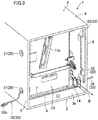
FIG. 3] FIG. 3 is a perspective view of the paper sheet processing device according to the embodiment in a state where the cover, the door portion, and the cap are detached, as viewed from the front-left side. - [
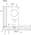
FIG. 4] FIG. 4 is a cross-sectional view schematically illustrating a state, on a longitudinal cross-section, of a portion near a bottom of a housing between the door portion and a storage position of a storage unit. - [
FIG. 5] FIG. 5 is a cross-sectional view schematically illustrating a state, on a transverse cross-section, of a position including a groove portion and a second hole of a second side wall. - [
FIG. 6] FIG. 6 is a block diagram illustrating a functional configuration between a control device and each of a power supply line and a communication line. - [
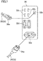
FIG. 7] FIG. 7 is a schematic diagram schematically illustrating a connection relationship between terminal portions of the control device and first ends of wires. - [
FIG. 8] FIG. 8 is a diagram corresponding toFIG. 3 and illustrating modification 1 of the paper sheet processing device according to the embodiment. - [
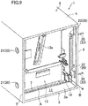
FIG. 9] FIG. 9 is a diagram corresponding toFIG. 3 andillustrating modification 2 of the paper sheet processing device according to the embodiment. - [
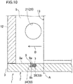
FIG. 10] FIG. 10 is a diagram corresponding toFIG. 4 andillustrating modification 2 of the paper sheet processing device according to the embodiment. - [
FIG. 11] FIG. 11 is a diagram corresponding toFIG. 3 andillustrating modification 3 of the paper sheet processing device according to the embodiment. - Embodiments of the present disclosure will be described below in detail with reference to the drawings. The following description of the embodiments is intrinsically illustrative, and is not intended to limit the present disclosure, the application thereof, or the usage thereof.
-
FIG. 1 to FIG. 3 illustrate the entirety of a paper sheet processing device 1 according to an embodiment of the present disclosure. The paper sheet processing device 1 is used for handling sheets such as banknotes and valuable mediums. Specifically, the paper sheet processing device 1 is used as, for example, a banknote handling device. The banknote handling device is installed in, for example, financial facilities such as banks, and retail stores. The banknote handling device is configured to perform various processing including depositing and dispensing. - In the following description, the upper (upper side) and the lower (lower side) represent a positional relationship in the up-down direction in the paper sheet processing device 1 shown in
FIG. 1 , the front (front side) and the rear (rear side) represent a positional relationship in the front-rear direction in the paper sheet processing device 1 shown inFIG. 1 , and the right side and the left side represent a positional relationship in the left-right direction in the paper sheet processing device 1 shown inFIG. 1 . - As shown in
FIG. 1 to FIG. 3 , the paper sheet processing device 1 includes ahousing 2. Thehousing 2 functions as a safe in which banknotes are stored. A display, a sheet inlet, and the like, which are not illustrated, are disposed on thehousing 2. Thehousing 2 is, for example, substantially rectangular-parallelepiped-box-shaped. Specifically, thehousing 2 has abottom 3, atop portion 4, afirst side wall 5, and asecond side wall 6. - The
bottom 3 and thetop portion 4 are disposed so as to face each other in the up-down direction. Each of thebottom 3 and thetop portion 4 is substantially plate-shaped. Thetop portion 4 has an inlet/outlet opening 4a through which sheets such as banknotes and valuable mediums are fed in and withdrawn between a not-illustrated handling unit (handling unit: includes the display, the sheet inlet, and the like which are not illustrated) disposed above the paper sheet processing device 1, and astorage unit 13 described below. In a case where the paper sheet processing device 1 is used as a banknote handling device, each of thebottom 3 and thetop portion 4 preferably has a thickness of, for example, 12.5 mm. - As shown in
FIG. 2 to FIG. 4 , thebottom 3 has aninner bottom 3a facing the inside of thehousing 2. As shown also inFIG. 5 , theinner bottom 3a has agroove portion 7. Thegroove portion 7 is formed so as to extend between thefirst side wall 5 and thesecond side wall 6 in the left-right direction. Thegroove portion 7 is, for example, straight-line-shaped. Thegroove portion 7 is formed so as to be recessed downward from theinner bottom 3a of thebottom 3. Thegroove portion 7 is formed in a well-like shape as viewed in the direction in which thegroove portion 7 extends. Thegroove portion 7 is disposed between adoor portion 12 and a storage position A at which thestorage unit 13 is stored in thehousing 2, in a direction in which thestorage unit 13 described below is drawn, that is, in an arrow B direction shown inFIG. 2 to FIG. 4 . - As shown in
FIG. 4 andFIG. 5 , thegroove portion 7 may have acover 8. Thecover 8 is configured to cover a power supply line 34 (wire 33), described below, stored at thegroove portion 7 from above thepower supply line 34. In the present embodiment, thecover 8 is substantially plate-shaped in a cross-sectional view. Thecover 8 is elongated in the left-right direction as compared with the front-rear direction. Thecover 8 is mounted to thegroove portion 7 such that the upper surface of thecover 8 is flush with theinner bottom 3a of thebottom 3. The left and the right end portions of thecover 8 are spaced from the inner wall surfaces of thefirst side wall 5 and thesecond side wall 6, respectively (seeFIG. 5 ). - As shown in
FIG. 1 to FIG. 3 , thefirst side wall 5 and thesecond side wall 6 are disposed so as to face each other in the horizontal direction and in the direction orthogonal to the direction in which thestorage unit 13 described below is drawn. That is, in the present embodiment, thefirst side wall 5 and thesecond side wall 6 are disposed so as to face each other in the left-right direction. - A lower end portion of the
first side wall 5 is connected to a left side end portion of the bottom 3 in the left-right direction. An upper end portion of thefirst side wall 5 is connected to a left side end portion of thetop portion 4 in the left-right direction. - A lower end portion of the
second side wall 6 is connected to a right side end portion of the bottom 3 in the left-right direction. An upper end portion of thesecond side wall 6 is connected to a right side end portion of thetop portion 4 in the left-right direction. - Each of the
first side wall 5 and thesecond side wall 6 is substantially plate-shaped. In a case where the paper sheet processing device 1 is used as a banknote handling device, each of thefirst side wall 5 and thesecond side wall 6 preferably has a thickness of, for example, 12.5 mm. - As shown in
FIG. 2 andFIG. 3 , an openingportion 11 is formed on the front surface side of thehousing 2 so as to be surrounded by thebottom 3, thetop portion 4, thefirst side wall 5, and thesecond side wall 6. In other words, the openingportion 11 is a front surface side end portion of thehousing 2 in a frame surrounded by thebottom 3, thetop portion 4, thefirst side wall 5, and thesecond side wall 6. As shown inFIG. 1 andFIG. 4 , thedoor portion 12 is disposed on the front surface side of thehousing 2 so as to close or open the openingportion 11. Specifically, thedoor portion 12 is configured to close or open the openingportion 11 by means ofhinge portions 12a mounted to thefirst side wall 5. - As shown in
FIG. 2 to FIG. 5 , the paper sheet processing device 1 includes thestorage unit 13. Thestorage unit 13 is used for storing sheets such as banknotes. Thestorage unit 13 is disposed in thehousing 2. Thestorage unit 13 is configured to be drawable through the openingportion 11 to outside of thehousing 2 when thedoor portion 12 is opened. Specifically, thestorage unit 13 is configured to be drawn forward from thehousing 2 along the arrow B direction. Ahandle 13a for drawing thestorage unit 13 is disposed on the front surface side of thestorage unit 13. - As shown in
FIG. 2 andFIG. 3 , aguide 14 is disposed at each of thefirst side wall 5 and thesecond side wall 6. Theguide 14 is used for drawing thestorage unit 13 through the openingportion 11 to outside of thehousing 2. Eachguide 14 extends in the front-rear direction in thehousing 2. Eachguide 14 is rail-shaped. Theguides 14 have back surfaces spaced from inner wall surfaces of thefirst side wall 5 and thesecond side wall 6, respectively (seeFIG. 5 ). In other words, therail 14 on thefirst side wall 5 side is spaced from thefirst side wall 5 and therail 14 on thesecond side wall 6 side is spaced from thesecond side wall 6. - As shown in
FIG. 2 , theguide 14 located at thefirst side wall 5 is disposed between two first holes 21 (described below) aligned in the up-down direction. As shown inFIG. 3 andFIG. 5 , theguide 14 located at thesecond side wall 6 is disposed below asecond hole 22 located on the lower side of thesecond side wall 6 in the up-down direction. - As shown in
FIG. 1 to FIG. 3 , thefirst side wall 5 and thesecond side wall 6 have a plurality ofholes 20. Eachhole 20 is configured so as to extend a second end of eachwire 33 described below from inside of thehousing 2 to outside of thehousing 2. In the present embodiment, a plurality of theholes 20 are disposed. More specifically, theholes 20 include a plurality (two in the illustrated example) of thefirst holes 21 and a plurality (two in the illustrated example) of the second holes 22. - As shown in
FIG. 2 to FIG. 4 , thefirst holes 21 are disposed at thefirst side wall 5. Each of thefirst holes 21 penetrates through thefirst side wall 5 from inside of thehousing 2 toward outside of thehousing 2. Each of thefirst holes 21 has a round shape. The shape of thefirst hole 21 is not limited to a round shape, and may be, for example, an ellipsoidal shape, a triangular shape, or a quadrangular shape. - The
first holes 21 are spaced from each other in the up-down direction. Thefirst holes 21 are disposed between thedoor portion 12 and thestorage unit 13 located at the storage position A, in the direction in which thestorage unit 13 is drawn. - As shown in
FIG. 2 andFIG. 3 , thesecond holes 22 are disposed at thesecond side wall 6. Similarly to thefirst holes 21, each of thesecond holes 22 penetrates through thesecond side wall 6 from inside of thehousing 2 toward outside of the housing 2 (seeFIG. 5 ). Each of thesecond holes 22 has a round shape. The shape of thesecond hole 22 is not limited to a round shape, and may be, for example, an ellipsoidal shape, a triangular shape, or a quadrangular shape. - The
second holes 22 are spaced from each other in the up-down direction. Thesecond holes 22 are disposed between thedoor portion 12 and thestorage unit 13 located at the storage position A, in the direction in which thestorage unit 13 is drawn. - As shown in
FIG. 1 to FIG. 3 , the paper sheet processing device 1 includes acap 23. Thecap 23 is used for closing eachhole 20 through which thewire 33 described below does not pass. A plurality of thecaps 23 may be disposed. In the present embodiment, thecap 23 is mounted to thefirst hole 21 disposed on the upper side of thefirst side wall 5. Thecap 23 is mounted also to thesecond hole 22 disposed on the upper side of thesecond side wall 6. - As shown in
FIG. 2 , the paper sheet processing device 1 includes acontrol device 30. Specifically, thecontrol device 30 is implemented as a computer. Thecontrol device 30 is disposed in thehousing 2. Specifically, thecontrol device 30 is disposed on the upper side in thehousing 2. Thecontrol device 30 is disposed between thefirst side wall 5 and thestorage unit 13 in the left-right direction. - As shown in
FIG. 6 , thecontrol device 30 has acontrol board 31. Thecontrol board 31 is used for controlling the operation of the paper sheet processing device 1. Specifically, thecontrol board 31 has a control program incorporated mainly for controlling the operation of thestorage unit 13. - As shown in
FIG. 7 , thecontrol device 30 hasterminal portions 32a to 32d for connection of each of thewires 33 described below. Each of theterminal portions 32a to 32d is electrically connected to thecontrol board 31. Theterminal portions 32a to 32d are disposed on the front surface side of thecontrol device 30. - The
terminal portion 32a is configured to connect thepower supply line 34 described below. Each of theterminal portions 32b to 32d is configured to connect acommunication line 35 described below. Specifically, theterminal portion 32b is used for connection of a LAN (local area network). Theterminal portion 32c is used for connection of a USB (universal serial bus). Theterminal portion 32d is used for connection to a display device as an external device. - As shown in
FIG. 2 andFIG. 3 , the paper sheet processing device 1 includes thewire 33. Onewire 33 or a plurality of thewires 33 may be disposed. Each of thewires 33 has electric conductivity. Each of thewires 33 is used for carrying electric current or a signal. As shown inFIG. 6 andFIG. 7 , thewire 33 is implemented as a wire (thepower supply line 34, the communication line 35) depending on the usage. - The
power supply line 34 has afirst end 34a. Thepower supply line 34 is configured such that thefirst end 34a is electrically connected to thecontrol board 31 via theterminal portion 32a. - The
power supply line 34 has asecond end 34b. Thepower supply line 34 is configured such that thesecond end 34b is electrically connected to, for example, a power receptacle (not shown) disposed outside the paper sheet processing device 1. - As shown in
FIG. 2 , thepower supply line 34 passes between the inner wall surface of thefirst side wall 5 and the back side of theguide 14. As shown also inFIG. 3 , thepower supply line 34 is disposed so as to be stored at thegroove portion 7. Thepower supply line 34 is wired so as to extend from thefirst side wall 5 toward thesecond side wall 6 in the left-right direction in a state where thepower supply line 34 is stored at thegroove portion 7. As shown inFIG. 3 andFIG. 5 , thepower supply line 34 passes between the inner wall surface of thesecond side wall 6 and the back side of theguide 14. Thesecond end 34b of thepower supply line 34 is extended to outside of thehousing 2 through thesecond hole 22 disposed on the lower side of thesecond side wall 6. - Next, as shown in
FIG. 6 andFIG. 7 , in the present embodiment, thecommunication line 35 is illustrated as a LAN cable. Thecommunication line 35 is not limited to the LAN cable, and may be implemented as a communication line as a USB cable or a communication line for connection to a display device as an external device. - The
communication line 35 has afirst end 35a. Thecommunication line 35 is configured such that thefirst end 35a is electrically connected to thecontrol board 31 via the terminal portion 32 of thecontrol device 30. - The
communication line 35 has asecond end 35b. Thecommunication line 35 is configured such that thesecond end 35b is electrically connected to an external device (not shown) disposed outside the paper sheet processing device 1. - As shown in
FIG. 2 , thecommunication line 35 passes between the inner wall surface of thefirst side wall 5 and the back side of theguide 14. Thesecond end 35b of thecommunication line 35 is extended to outside of thehousing 2 through thefirst hole 21 disposed on the lower side of thefirst side wall 5. That is, thesecond end 35b of thecommunication line 35 is extended to outside of thehousing 2 through thefirst hole 21 through which thepower supply line 34 does not pass. - As described above, in the paper sheet processing device 1, the second end of each
wire 33 connected to thecontrol board 31 can be extended from the side surface of thehousing 2 to outside of thehousing 2 through thehole 20 disposed at at least one of thefirst side wall 5 and thesecond side wall 6. Therefore, in a case where, for example, the paper sheet processing device 1 is installed in a state where a gap is very small between the back surface of thehousing 2 and a wall surface of a room in a building, the second end of thewire 33 is easily extended from the side surface of thehousing 2 to outside of thehousing 2 through thehole 20. Furthermore, also in a case where, for example, the paper sheet processing device 1 is installed under a desk in a state where a working space under the desk is very small, since the second end of thewire 33 is extended from the side surface of thehousing 2 to outside of thehousing 2, the wiring work is facilitated. Furthermore, also in a case where, for example, anotherwire 33 is additionally wired in order to additionally dispose an external device during maintenance after the paper sheet processing device 1 has been installed, since at least one option for extending the second end of thewire 33 to outside of the device is provided, the wiring work and a work for adding the external device are facilitated. Therefore, in the paper sheet processing device 1, the wiring work efficiency can be enhanced regardless of an environment or a state in which the paper sheet processing device 1 is installed. - The
second end 34b of thepower supply line 34 and thesecond end 35b of thecommunication line 35 are each extended through any of thefirst holes 21 and thesecond holes 22 to outside of thehousing 2. Thus, in the paper sheet processing device 1, a plurality of options for extending each of thesecond end 34b of thepower supply line 34 and thesecond end 35b of thecommunication line 35 to outside of the device are provided. Therefore, the wiring work efficiency can be further enhanced regardless of an environment or a state in which the paper sheet processing device 1 is installed. - In the present embodiment, the
second end 34b of thepower supply line 34 is extended to outside of thehousing 2 through thesecond hole 22. Thesecond end 35b of thecommunication line 35 is extended to outside of thehousing 2 through thefirst hole 21 through which thepower supply line 34 does not pass. That is, thesecond end 34b of thepower supply line 34 and thesecond end 35b of thecommunication line 35 are extended to outside of thehousing 2 through thesecond hole 22 and thefirst hole 21, respectively, in a separated state. Thus, thepower supply line 34 and thecommunication line 35 can be wired so as to be separated from each other. As a result, thepower supply line 34 and thecommunication line 35 are unlikely to exert electrical influence on each other, thereby inhibiting noise from causing communication error or the like. - The
hole 20 through which thewire 33 does not pass is closed by thecap 23, whereby thehousing 2 can be nearly sealed. Thus, a stored state of sheets in thehousing 2 can be maintained good. In a case where thehole 20 through which thewire 33 does not pass is closed by thecap 23, degradation in the design of the outer appearance of the paper sheet processing device 1 can be prevented. - In the paper sheet processing device 1, since the
wire 33 is disposed so as to be stored at thegroove portion 7, also in a case where thewire 33 is wired so as to extend between thefirst side wall 5 and thesecond side wall 6, thewire 33 can be stored neatly in thehousing 2. - In the paper sheet processing device 1, the
cover 8 can protect thewire 33 stored at thegroove portion 7. - The
wire 33 is stored at thegroove portion 7 disposed between thedoor portion 12 and the storage position A at which thestorage unit 13 is stored in thehousing 2, in the direction in which thestorage unit 13 is drawn. Therefore, also in a case where thewire 33 is wired so as to extend between thefirst side wall 5 and thesecond side wall 6, thestorage unit 13 can be drawn through the openingportion 11 to outside of thehousing 2 regardless of whether thewire 33 is present or absent. - The plurality of
holes 20 are disposed between thedoor portion 12 and thestorage unit 13 located at the storage position A, in the direction in which thestorage unit 13 is drawn. That is, the plurality ofholes 20 and thegroove portion 7 are collectively disposed between thedoor portion 12 and thestorage unit 13 located at the storage position A, in the direction in which thestorage unit 13 is drawn. Thus, also in a case where thepower supply line 34 is wired so as to extend between thefirst side wall 5 and thesecond side wall 6 as in the present embodiment, thepower supply line 34 stored at thegroove portion 7 can be easily wired so as to extend toward thesecond hole 22. - Each
wire 33 passes between the inner wall surface of thefirst side wall 5 or thesecond side wall 6 and the back side of theguide 14. Therefore, an operation for drawing thestorage unit 13 may not be inhibited due to a wiring state of eachwire 33. - The
guide 14 located at thefirst side wall 5 is disposed between the twofirst holes 21 aligned with each other in the up-down direction. Thus, each of thewires 33 can be extended to outside of thehousing 2 through either thefirst hole 21 disposed above theguide 14 or thefirst hole 21 disposed below theguide 14 without influencing an operation for drawing thestorage unit 13. - The
first side wall 5 and thesecond side wall 6 are disposed so as to face each other in the horizontal direction and in the direction orthogonal to the drawing direction. Thus, in the paper sheet processing device 1, thestorage unit 13 can be easily drawn through the openingportion 11 to outside of thehousing 2 when thedoor portion 12 is opened. - In the above-described embodiment, the
second end 34b of thepower supply line 34 is extended to outside of thehousing 2 through thesecond hole 22. However, the present disclosure is not limited to this configuration. - For example, as in modification 1 shown in
FIG. 8 . thesecond end 34b of thepower supply line 34 may be extended to outside of thehousing 2 through thefirst hole 21 disposed on the upper side of thefirst side wall 5. That is, the second end of thecommunication line 35 is extended to outside of thehousing 2 through thefirst hole 21 through which thepower supply line 34 does not pass. - In modification 1, each of the
second end 34b of thepower supply line 34 and thesecond end 35b of thecommunication line 35 is extended to outside of thehousing 2 through one of the twofirst holes 21. That is, also in this modification, as in the above-described embodiment, a plurality of options for extending each of thesecond end 34b of thepower supply line 34 and thesecond end 35b of thecommunication line 35 to outside of the device are provided. Since the twofirst holes 21 are spaced from each other in the up-down direction of thefirst side wall 5, thesecond end 34b of thepower supply line 34 and thesecond end 35b of thecommunication line 35 can be extended to outside of thehousing 2 through thefirst holes 21, respectively, in a separated state. - Therefore, also in the configuration as described in modification 1, similarly to the above-described embodiment, the
power supply line 34 and thecommunication line 35 are unlikely to exert electrical influence on each other, thereby inhibiting noise from causing communication error or the like. - In the above-described embodiment, the
second end 35b of thecommunication line 35 is extended to outside of thehousing 2 through thefirst hole 21 disposed on the lower side of thefirst side wall 5. However, the present disclosure is not limited to this configuration. - For example, as in
modification 2 shown inFIG. 9 andFIG. 10 , thesecond end 35b of thecommunication line 35 may be extended to outside of thehousing 2 through thesecond hole 22 disposed on the upper side of thesecond side wall 6. That is, thesecond end 35b of thecommunication line 35 is extended to outside of thehousing 2 through thesecond hole 22 through which thepower supply line 34 does not pass. - In
modification 2, thesecond end 34b of thepower supply line 34 and thesecond end 35b of thecommunication line 35 are each extended to outside of thehousing 2 through one of the twosecond holes 22. That is, also in this modification, as in the above-described embodiment, a plurality of options for extending each of thesecond end 34b of thepower supply line 34 and thesecond end 35b of thecommunication line 35 to outside of the device are provided. Since the twosecond holes 22 are spaced from each other in the up-down direction of thesecond side wall 6, thesecond end 34b of thepower supply line 34 and thesecond end 35b of thecommunication line 35 can be extended to outside of thehousing 2 through thesecond holes 22, respectively, in a separated state. - Furthermore, in
modification 2, instead of thecover 8 of the above-described embodiment, acover 9 having a shape partially different from that of thecover 8 is used. Thecover 9 is substantially T-shaped in a cross-sectional view. Specifically, thecover 9 has aplate portion 9a, and aseparation wall portion 9b projecting downward from almost the center of theplate portion 9a. By theseparation wall portion 9b of thecover 9, thepower supply line 34 and thecommunication line 35 can be stored at thegroove portion 7 so as to be separated from each other in thegroove portion 7. - Therefore, also in the configuration as described in
modification 2, thepower supply line 34 and thecommunication line 35 are unlikely to exert electrical influence on each other, thereby inhibiting noise from causing communication error or the like. - In the above-described embodiment, the
second end 35b of thecommunication line 35 is extended to outside of thehousing 2 through thefirst hole 21 through which thepower supply line 34 does not pass. However, the present disclosure is not limited to this configuration. That is, thesecond end 35b of thecommunication line 35 may be extended to outside of thehousing 2 through thefirst hole 21 or thesecond hole 22 through which thepower supply line 34 passes. - For example, as in
modification 3 shown inFIG. 11 , each of thesecond end 34b of thepower supply line 34 and thesecond end 35b of thecommunication line 35 may be extended to outside of thehousing 2 through thefirst hole 21 disposed on the lower side of thefirst side wall 5. In such a configuration, thepower supply line 34 and thecommunication line 35 connected to thecontrol board 31 can be collected into one and extended to outside of thehousing 2 through thefirst hole 21. Thus, the wiring work for thepower supply line 34 and thecommunication line 35 can be simplified. - In the above-described embodiment, the
guide 14 located at thesecond side wall 6 is disposed below thesecond hole 22 located on the lower side of thesecond side wall 6 in the up-down direction. However, the present disclosure is not limited to this configuration. That is, theguide 14 located at thesecond side wall 6 may be disposed between the twosecond holes 22 aligned with each other in the up-down direction in thesecond side wall 6. Thus, thewire 33 can be extended to outside of thehousing 2 through one of thesecond hole 22 disposed above theguide 14 or thesecond hole 22 disposed below theguide 14 without influencing an operation for drawing thestorage unit 13. - In the above-described embodiment, the number of the
communication lines 35 provided is one. However, the present disclosure is not limited to this configuration. That is, a plurality of thecommunication lines 35 may be provided. - The present disclosure has been described above based on the embodiments. However, the present disclosure is not limited to the above-described embodiments, and various modifications can be made in the scope of the present disclosure.
- The present disclosure can be industrially used as a paper sheet processing device for handling sheets such as banknotes and valuable mediums.
-
- 1
- paper sheet processing device
- 2
- housing
- 3
- bottom
- 3a
- inner bottom
- 5
- first side wall
- 6
- second side wall
- 7
- groove portion
- 8, 9
- cover
- 11
- opening portion
- 12
- door portion
- 13
- storage unit
- 14
- guide
- 20
- hole
- 21
- first hole
- 22
- second hole
- 23
- cap
- 30
- control device
- 31
- control board
- 32a to 32d
- terminal portion
- 33
- wire
- 34
- power supply line
- 35
- communication line
- A
- storage position
Claims (14)
- A paper sheet processing device comprising:a housing of the paper sheet processing device;a control board disposed in the housing for controlling an operation of the paper sheet processing device; andat least one conductive wire having a first end connected to the control board,whereinthe housing includesa bottom, anda first side wall and a second side wall connected to both ends of the bottom,at least one hole is provided at at least one of the first side wall and the second side wall so as to penetrate therethrough from inside of the housing to outside of the housing, andthe hole allows a second end of the wire to extend from inside of the housing to outside of the housing.
- The paper sheet processing device according to claim 1, wherein
the hole includesat least one first hole disposed at the first side wall, andat least one second hole disposed at the second side wall,the wire includes a power supply line having a first end connected to the control board,
the wire includes a communication line having a first end connected to the control board,
a second end of the power supply line is extended to outside of the housing through one of the at least one first hole and the at least one second hole, and
a second end of the communication line is extended to outside of the housing through one of the at least one first hole and the at least one second hole. - The paper sheet processing device according to claim 2, wherein
the second end of the power supply line is extended to outside of the housing through one of the at least one first hole and the at least one second hole, and
the second end of the communication line is extended to outside of the housing through the first hole or the second hole through which the power supply line passes. - The paper sheet processing device according to claim 2, wherein
the second end of the power supply line is extended to outside of the housing through one of the at least one first hole and the at least one second hole, and
the second end of the communication line is extended to outside of the housing through the first hole or the second hole through which the power supply line does not pass. - The paper sheet processing device according to any one of claims 2 to 4, wherein
the first hole comprises a plurality of first holes, and
the plurality of first holes are spaced from each other in an up-down direction of the first side wall. - The paper sheet processing device according to claim 5, wherein
the second hole comprises a plurality of second holes, and
the plurality of second holes are spaced from each other in an up-down direction of the second side wall. - The paper sheet processing device according to any one of claims 1 to 6, further comprising a cap for closing the hole through which the wire does not pass, among the holes disposed at at least one of the first side wall and the second side wall.
- The paper sheet processing device according to claim 1 or 2, wherein
the bottom has an inner bottom facing inside of the housing,
the inner bottom has a groove portion extending between the first side wall and the second side wall, and
the wire is disposed so as to be stored at the groove portion. - The paper sheet processing device according to claim 8, further comprising a cover for covering the wire stored at the groove portion, from above the wire.
- The paper sheet processing device according to claim 8 or 9, wherein
the housing includesan opening portion provided at a front surface side of the housing, anda door portion for closing or opening the opening portion,the paper sheet processing device further comprises a storage unit disposed in the housing for storing sheets,
the storage unit is drawable to outside of the housing through the opening portion when the door portion is opened, and
the groove portion is disposed between the door portion and a storage position at which the storage unit is stored in the housing, in a drawing direction of the storage unit. - The paper sheet processing device according to claim 10, wherein the hole is disposed between the door portion and the storage unit located at the storage position, in the drawing direction of the storage unit.
- The paper sheet processing device according to claim 10 or 11, wherein
each of the first side wall and the second side wall has a guide for drawing the storage unit to outside of the housing through the opening portion, and
the wire passes between a back side of the guide and an inner wall surface of each of the first side wall and the second side wall. - The paper sheet processing device according to claim 12, wherein
the hole comprises a plurality of holes, and the plurality of holes are spaced from each other in an up-down direction at at least one of the first side wall and the second side wall, and
the guide is disposed between the holes at at least one of the first side wall and the second side wall. - The paper sheet processing device according to any one of claims 10 to 13, wherein the first side wall and the second side wall are disposed so as to face each other in a horizontal direction and a direction orthogonal to the drawing direction.
Applications Claiming Priority (2)
| Application Number | Priority Date | Filing Date | Title |
|---|---|---|---|
| JP2018180432A JP2020052640A (en) | 2018-09-26 | 2018-09-26 | Paper processing apparatus |
| PCT/JP2019/036204 WO2020066716A1 (en) | 2018-09-26 | 2019-09-13 | Paper sheet processing device |
Publications (3)
| Publication Number | Publication Date |
|---|---|
| EP3859694A1 true EP3859694A1 (en) | 2021-08-04 |
| EP3859694A4 EP3859694A4 (en) | 2021-11-24 |
| EP3859694B1 EP3859694B1 (en) | 2023-11-01 |
Family
ID=69952400
Family Applications (1)
| Application Number | Title | Priority Date | Filing Date |
|---|---|---|---|
| EP19866362.7A Active EP3859694B1 (en) | 2018-09-26 | 2019-09-13 | Paper sheet processing device |
Country Status (4)
| Country | Link |
|---|---|
| US (1) | US11941935B2 (en) |
| EP (1) | EP3859694B1 (en) |
| JP (1) | JP2020052640A (en) |
| WO (1) | WO2020066716A1 (en) |
Family Cites Families (16)
| Publication number | Priority date | Publication date | Assignee | Title |
|---|---|---|---|---|
| JPS60167549U (en) * | 1984-04-14 | 1985-11-07 | 共栄工業株式会社 | Cord wiring device in storage sheds, etc. |
| JPH0513766U (en) * | 1991-07-31 | 1993-02-23 | 沖電気工業株式会社 | Printer |
| US5931103A (en) * | 1997-05-21 | 1999-08-03 | Huang; Huei Mien | Computer desk |
| JP4256826B2 (en) * | 2004-07-30 | 2009-04-22 | 矢崎総業株式会社 | Power supply device |
| JP2008277048A (en) * | 2007-04-26 | 2008-11-13 | Toshiba Corp | Electronics |
| KR100956136B1 (en) * | 2008-02-15 | 2010-05-06 | 전남대학교산학협력단 | Safe deposit box to prevent cash takeover by robbers and employees |
| US7889961B2 (en) * | 2008-03-27 | 2011-02-15 | Corning Cable Systems Llc | Compact, high-density adapter module, housing assembly and frame assembly for optical fiber telecommunications |
| JP2011159081A (en) * | 2010-01-29 | 2011-08-18 | Toshiba Corp | Electronic device |
| CN102856746A (en) * | 2011-06-30 | 2013-01-02 | 鸿富锦精密工业(深圳)有限公司 | Cable containing device and cable module with same |
| JP6041579B2 (en) | 2012-08-28 | 2016-12-14 | グローリー株式会社 | Banknote handling equipment |
| US8857597B2 (en) | 2012-07-24 | 2014-10-14 | Glory Ltd. | Banknote handling apparatus |
| US9585474B2 (en) * | 2013-07-17 | 2017-03-07 | Whirlpool Corporation | Traveling harness system |
| JP6471496B2 (en) * | 2014-12-26 | 2019-02-20 | 沖電気工業株式会社 | Medium processing apparatus and medium transaction apparatus |
| US10127538B2 (en) * | 2015-09-10 | 2018-11-13 | Innowi Inc. | Smart integrated point of sale system |
| JP6747249B2 (en) | 2015-11-28 | 2020-08-26 | 沖電気工業株式会社 | Automatic transaction equipment |
| CN207008769U (en) * | 2017-08-15 | 2018-02-13 | 刘学群 | A kind of cash register receiver |
-
2018
- 2018-09-26 JP JP2018180432A patent/JP2020052640A/en active Pending
-
2019
- 2019-09-13 EP EP19866362.7A patent/EP3859694B1/en active Active
- 2019-09-13 WO PCT/JP2019/036204 patent/WO2020066716A1/en not_active Ceased
-
2021
- 2021-03-25 US US17/211,842 patent/US11941935B2/en active Active
Also Published As
| Publication number | Publication date |
|---|---|
| WO2020066716A1 (en) | 2020-04-02 |
| EP3859694A4 (en) | 2021-11-24 |
| JP2020052640A (en) | 2020-04-02 |
| EP3859694B1 (en) | 2023-11-01 |
| US11941935B2 (en) | 2024-03-26 |
| US20210209887A1 (en) | 2021-07-08 |
Similar Documents
| Publication | Publication Date | Title |
|---|---|---|
| CN104247092B (en) | Wiring module | |
| JPS5833908A (en) | control center | |
| JPWO2015025489A1 (en) | Electric equipment with built-in cable duct | |
| JP5831416B2 (en) | Wire harness and protective equipment | |
| CN105431965A (en) | Distribution module | |
| EP3859694B1 (en) | Paper sheet processing device | |
| EP3828038B1 (en) | Electrical connection box and wire harness | |
| CN111550965B (en) | Wiring mechanism and refrigerator with same | |
| JP2019198135A (en) | Wire harness protector and wire harness with protector | |
| JP2015125199A (en) | Image forming apparatus | |
| CN104519692A (en) | Cabinet and method for avoiding PDU (power distribution unit) to invade and occupy maintenance space of same | |
| JP6068884B2 (en) | Battery pack terminal protection cover | |
| CN218850159U (en) | High-low voltage power distribution cabinet and power supply system | |
| CN101119617A (en) | Cabinet and communication device | |
| CN105873401B (en) | Wire controller | |
| CN209562981U (en) | A kind of mine belt conveyor driving protection control device | |
| CN219760275U (en) | Wire harness frame for power distribution cabinet | |
| CN211982204U (en) | Electrostatic protection device of feed cabinet | |
| CN216213824U (en) | Box structure and battery module with same | |
| CN218182626U (en) | Wiring harness channel data signal connector | |
| KR20210154552A (en) | Optical fiber distribution box | |
| CN220570103U (en) | Electrical device | |
| CN116238553B (en) | Double-layer partition wall and rail vehicle | |
| CN210721303U (en) | Case capable of horizontally and vertically mounting display card | |
| CN216626306U (en) | Pin-connected panel machine case cabinet |
Legal Events
| Date | Code | Title | Description |
|---|---|---|---|
| STAA | Information on the status of an ep patent application or granted ep patent |
Free format text: STATUS: THE INTERNATIONAL PUBLICATION HAS BEEN MADE |
|
| PUAI | Public reference made under article 153(3) epc to a published international application that has entered the european phase |
Free format text: ORIGINAL CODE: 0009012 |
|
| STAA | Information on the status of an ep patent application or granted ep patent |
Free format text: STATUS: REQUEST FOR EXAMINATION WAS MADE |
|
| 17P | Request for examination filed |
Effective date: 20210420 |
|
| AK | Designated contracting states |
Kind code of ref document: A1 Designated state(s): AL AT BE BG CH CY CZ DE DK EE ES FI FR GB GR HR HU IE IS IT LI LT LU LV MC MK MT NL NO PL PT RO RS SE SI SK SM TR |
|
| A4 | Supplementary search report drawn up and despatched |
Effective date: 20211022 |
|
| RIC1 | Information provided on ipc code assigned before grant |
Ipc: G07D 11/00 20190101ALI20211018BHEP Ipc: G07D 11/12 20190101AFI20211018BHEP |
|
| DAV | Request for validation of the european patent (deleted) | ||
| DAX | Request for extension of the european patent (deleted) | ||
| GRAP | Despatch of communication of intention to grant a patent |
Free format text: ORIGINAL CODE: EPIDOSNIGR1 |
|
| STAA | Information on the status of an ep patent application or granted ep patent |
Free format text: STATUS: GRANT OF PATENT IS INTENDED |
|
| INTG | Intention to grant announced |
Effective date: 20221005 |
|
| GRAJ | Information related to disapproval of communication of intention to grant by the applicant or resumption of examination proceedings by the epo deleted |
Free format text: ORIGINAL CODE: EPIDOSDIGR1 |
|
| STAA | Information on the status of an ep patent application or granted ep patent |
Free format text: STATUS: REQUEST FOR EXAMINATION WAS MADE |
|
| INTC | Intention to grant announced (deleted) | ||
| GRAP | Despatch of communication of intention to grant a patent |
Free format text: ORIGINAL CODE: EPIDOSNIGR1 |
|
| STAA | Information on the status of an ep patent application or granted ep patent |
Free format text: STATUS: GRANT OF PATENT IS INTENDED |
|
| INTG | Intention to grant announced |
Effective date: 20230509 |
|
| P01 | Opt-out of the competence of the unified patent court (upc) registered |
Effective date: 20230531 |
|
| GRAS | Grant fee paid |
Free format text: ORIGINAL CODE: EPIDOSNIGR3 |
|
| GRAA | (expected) grant |
Free format text: ORIGINAL CODE: 0009210 |
|
| STAA | Information on the status of an ep patent application or granted ep patent |
Free format text: STATUS: THE PATENT HAS BEEN GRANTED |
|
| AK | Designated contracting states |
Kind code of ref document: B1 Designated state(s): AL AT BE BG CH CY CZ DE DK EE ES FI FR GB GR HR HU IE IS IT LI LT LU LV MC MK MT NL NO PL PT RO RS SE SI SK SM TR |
|
| REG | Reference to a national code |
Ref country code: GB Ref legal event code: FG4D |
|
| REG | Reference to a national code |
Ref country code: CH Ref legal event code: EP |
|
| REG | Reference to a national code |
Ref country code: IE Ref legal event code: FG4D |
|
| REG | Reference to a national code |
Ref country code: DE Ref legal event code: R096 Ref document number: 602019040797 Country of ref document: DE |
|
| REG | Reference to a national code |
Ref country code: LT Ref legal event code: MG9D |
|
| REG | Reference to a national code |
Ref country code: NL Ref legal event code: MP Effective date: 20231101 |
|
| PG25 | Lapsed in a contracting state [announced via postgrant information from national office to epo] |
Ref country code: GR Free format text: LAPSE BECAUSE OF FAILURE TO SUBMIT A TRANSLATION OF THE DESCRIPTION OR TO PAY THE FEE WITHIN THE PRESCRIBED TIME-LIMIT Effective date: 20240202 |
|
| PG25 | Lapsed in a contracting state [announced via postgrant information from national office to epo] |
Ref country code: IS Free format text: LAPSE BECAUSE OF FAILURE TO SUBMIT A TRANSLATION OF THE DESCRIPTION OR TO PAY THE FEE WITHIN THE PRESCRIBED TIME-LIMIT Effective date: 20240301 |
|
| PG25 | Lapsed in a contracting state [announced via postgrant information from national office to epo] |
Ref country code: LT Free format text: LAPSE BECAUSE OF FAILURE TO SUBMIT A TRANSLATION OF THE DESCRIPTION OR TO PAY THE FEE WITHIN THE PRESCRIBED TIME-LIMIT Effective date: 20231101 |
|
| REG | Reference to a national code |
Ref country code: AT Ref legal event code: MK05 Ref document number: 1628120 Country of ref document: AT Kind code of ref document: T Effective date: 20231101 |
|
| PG25 | Lapsed in a contracting state [announced via postgrant information from national office to epo] |
Ref country code: NL Free format text: LAPSE BECAUSE OF FAILURE TO SUBMIT A TRANSLATION OF THE DESCRIPTION OR TO PAY THE FEE WITHIN THE PRESCRIBED TIME-LIMIT Effective date: 20231101 |
|
| PG25 | Lapsed in a contracting state [announced via postgrant information from national office to epo] |
Ref country code: AT Free format text: LAPSE BECAUSE OF FAILURE TO SUBMIT A TRANSLATION OF THE DESCRIPTION OR TO PAY THE FEE WITHIN THE PRESCRIBED TIME-LIMIT Effective date: 20231101 |
|
| PG25 | Lapsed in a contracting state [announced via postgrant information from national office to epo] |
Ref country code: ES Free format text: LAPSE BECAUSE OF FAILURE TO SUBMIT A TRANSLATION OF THE DESCRIPTION OR TO PAY THE FEE WITHIN THE PRESCRIBED TIME-LIMIT Effective date: 20231101 |
|
| PG25 | Lapsed in a contracting state [announced via postgrant information from national office to epo] |
Ref country code: NL Free format text: LAPSE BECAUSE OF FAILURE TO SUBMIT A TRANSLATION OF THE DESCRIPTION OR TO PAY THE FEE WITHIN THE PRESCRIBED TIME-LIMIT Effective date: 20231101 Ref country code: LT Free format text: LAPSE BECAUSE OF FAILURE TO SUBMIT A TRANSLATION OF THE DESCRIPTION OR TO PAY THE FEE WITHIN THE PRESCRIBED TIME-LIMIT Effective date: 20231101 Ref country code: IS Free format text: LAPSE BECAUSE OF FAILURE TO SUBMIT A TRANSLATION OF THE DESCRIPTION OR TO PAY THE FEE WITHIN THE PRESCRIBED TIME-LIMIT Effective date: 20240301 Ref country code: GR Free format text: LAPSE BECAUSE OF FAILURE TO SUBMIT A TRANSLATION OF THE DESCRIPTION OR TO PAY THE FEE WITHIN THE PRESCRIBED TIME-LIMIT Effective date: 20240202 Ref country code: ES Free format text: LAPSE BECAUSE OF FAILURE TO SUBMIT A TRANSLATION OF THE DESCRIPTION OR TO PAY THE FEE WITHIN THE PRESCRIBED TIME-LIMIT Effective date: 20231101 Ref country code: BG Free format text: LAPSE BECAUSE OF FAILURE TO SUBMIT A TRANSLATION OF THE DESCRIPTION OR TO PAY THE FEE WITHIN THE PRESCRIBED TIME-LIMIT Effective date: 20240201 Ref country code: AT Free format text: LAPSE BECAUSE OF FAILURE TO SUBMIT A TRANSLATION OF THE DESCRIPTION OR TO PAY THE FEE WITHIN THE PRESCRIBED TIME-LIMIT Effective date: 20231101 Ref country code: PT Free format text: LAPSE BECAUSE OF FAILURE TO SUBMIT A TRANSLATION OF THE DESCRIPTION OR TO PAY THE FEE WITHIN THE PRESCRIBED TIME-LIMIT Effective date: 20240301 |
|
| PG25 | Lapsed in a contracting state [announced via postgrant information from national office to epo] |
Ref country code: SE Free format text: LAPSE BECAUSE OF FAILURE TO SUBMIT A TRANSLATION OF THE DESCRIPTION OR TO PAY THE FEE WITHIN THE PRESCRIBED TIME-LIMIT Effective date: 20231101 Ref country code: RS Free format text: LAPSE BECAUSE OF FAILURE TO SUBMIT A TRANSLATION OF THE DESCRIPTION OR TO PAY THE FEE WITHIN THE PRESCRIBED TIME-LIMIT Effective date: 20231101 Ref country code: PL Free format text: LAPSE BECAUSE OF FAILURE TO SUBMIT A TRANSLATION OF THE DESCRIPTION OR TO PAY THE FEE WITHIN THE PRESCRIBED TIME-LIMIT Effective date: 20231101 Ref country code: NO Free format text: LAPSE BECAUSE OF FAILURE TO SUBMIT A TRANSLATION OF THE DESCRIPTION OR TO PAY THE FEE WITHIN THE PRESCRIBED TIME-LIMIT Effective date: 20240201 Ref country code: LV Free format text: LAPSE BECAUSE OF FAILURE TO SUBMIT A TRANSLATION OF THE DESCRIPTION OR TO PAY THE FEE WITHIN THE PRESCRIBED TIME-LIMIT Effective date: 20231101 Ref country code: HR Free format text: LAPSE BECAUSE OF FAILURE TO SUBMIT A TRANSLATION OF THE DESCRIPTION OR TO PAY THE FEE WITHIN THE PRESCRIBED TIME-LIMIT Effective date: 20231101 |
|
| PG25 | Lapsed in a contracting state [announced via postgrant information from national office to epo] |
Ref country code: DK Free format text: LAPSE BECAUSE OF FAILURE TO SUBMIT A TRANSLATION OF THE DESCRIPTION OR TO PAY THE FEE WITHIN THE PRESCRIBED TIME-LIMIT Effective date: 20231101 |
|
| PG25 | Lapsed in a contracting state [announced via postgrant information from national office to epo] |
Ref country code: CZ Free format text: LAPSE BECAUSE OF FAILURE TO SUBMIT A TRANSLATION OF THE DESCRIPTION OR TO PAY THE FEE WITHIN THE PRESCRIBED TIME-LIMIT Effective date: 20231101 |
|
| PG25 | Lapsed in a contracting state [announced via postgrant information from national office to epo] |
Ref country code: SK Free format text: LAPSE BECAUSE OF FAILURE TO SUBMIT A TRANSLATION OF THE DESCRIPTION OR TO PAY THE FEE WITHIN THE PRESCRIBED TIME-LIMIT Effective date: 20231101 |
|
| PG25 | Lapsed in a contracting state [announced via postgrant information from national office to epo] |
Ref country code: SM Free format text: LAPSE BECAUSE OF FAILURE TO SUBMIT A TRANSLATION OF THE DESCRIPTION OR TO PAY THE FEE WITHIN THE PRESCRIBED TIME-LIMIT Effective date: 20231101 Ref country code: SK Free format text: LAPSE BECAUSE OF FAILURE TO SUBMIT A TRANSLATION OF THE DESCRIPTION OR TO PAY THE FEE WITHIN THE PRESCRIBED TIME-LIMIT Effective date: 20231101 Ref country code: EE Free format text: LAPSE BECAUSE OF FAILURE TO SUBMIT A TRANSLATION OF THE DESCRIPTION OR TO PAY THE FEE WITHIN THE PRESCRIBED TIME-LIMIT Effective date: 20231101 Ref country code: DK Free format text: LAPSE BECAUSE OF FAILURE TO SUBMIT A TRANSLATION OF THE DESCRIPTION OR TO PAY THE FEE WITHIN THE PRESCRIBED TIME-LIMIT Effective date: 20231101 Ref country code: CZ Free format text: LAPSE BECAUSE OF FAILURE TO SUBMIT A TRANSLATION OF THE DESCRIPTION OR TO PAY THE FEE WITHIN THE PRESCRIBED TIME-LIMIT Effective date: 20231101 |
|
| REG | Reference to a national code |
Ref country code: DE Ref legal event code: R097 Ref document number: 602019040797 Country of ref document: DE |
|
| PLBE | No opposition filed within time limit |
Free format text: ORIGINAL CODE: 0009261 |
|
| STAA | Information on the status of an ep patent application or granted ep patent |
Free format text: STATUS: NO OPPOSITION FILED WITHIN TIME LIMIT |
|
| 26N | No opposition filed |
Effective date: 20240802 |
|
| PG25 | Lapsed in a contracting state [announced via postgrant information from national office to epo] |
Ref country code: SI Free format text: LAPSE BECAUSE OF FAILURE TO SUBMIT A TRANSLATION OF THE DESCRIPTION OR TO PAY THE FEE WITHIN THE PRESCRIBED TIME-LIMIT Effective date: 20231101 |
|
| PG25 | Lapsed in a contracting state [announced via postgrant information from national office to epo] |
Ref country code: SI Free format text: LAPSE BECAUSE OF FAILURE TO SUBMIT A TRANSLATION OF THE DESCRIPTION OR TO PAY THE FEE WITHIN THE PRESCRIBED TIME-LIMIT Effective date: 20231101 |
|
| PG25 | Lapsed in a contracting state [announced via postgrant information from national office to epo] |
Ref country code: MC Free format text: LAPSE BECAUSE OF FAILURE TO SUBMIT A TRANSLATION OF THE DESCRIPTION OR TO PAY THE FEE WITHIN THE PRESCRIBED TIME-LIMIT Effective date: 20231101 |
|
| REG | Reference to a national code |
Ref country code: CH Ref legal event code: PL |
|
| PG25 | Lapsed in a contracting state [announced via postgrant information from national office to epo] |
Ref country code: LU Free format text: LAPSE BECAUSE OF NON-PAYMENT OF DUE FEES Effective date: 20240913 |
|
| GBPC | Gb: european patent ceased through non-payment of renewal fee |
Effective date: 20240913 |
|
| PG25 | Lapsed in a contracting state [announced via postgrant information from national office to epo] |
Ref country code: GB Free format text: LAPSE BECAUSE OF NON-PAYMENT OF DUE FEES Effective date: 20240913 |
|
| REG | Reference to a national code |
Ref country code: BE Ref legal event code: MM Effective date: 20240930 |
|
| PG25 | Lapsed in a contracting state [announced via postgrant information from national office to epo] |
Ref country code: BE Free format text: LAPSE BECAUSE OF NON-PAYMENT OF DUE FEES Effective date: 20240930 |
|
| PG25 | Lapsed in a contracting state [announced via postgrant information from national office to epo] |
Ref country code: CH Free format text: LAPSE BECAUSE OF NON-PAYMENT OF DUE FEES Effective date: 20240930 |
|
| PG25 | Lapsed in a contracting state [announced via postgrant information from national office to epo] |
Ref country code: IE Free format text: LAPSE BECAUSE OF NON-PAYMENT OF DUE FEES Effective date: 20240913 |
|
| PG25 | Lapsed in a contracting state [announced via postgrant information from national office to epo] |
Ref country code: FI Free format text: LAPSE BECAUSE OF FAILURE TO SUBMIT A TRANSLATION OF THE DESCRIPTION OR TO PAY THE FEE WITHIN THE PRESCRIBED TIME-LIMIT Effective date: 20231101 |
|
| PGFP | Annual fee paid to national office [announced via postgrant information from national office to epo] |
Ref country code: DE Payment date: 20250919 Year of fee payment: 7 |
|
| PGFP | Annual fee paid to national office [announced via postgrant information from national office to epo] |
Ref country code: IT Payment date: 20250923 Year of fee payment: 7 |
|
| PGFP | Annual fee paid to national office [announced via postgrant information from national office to epo] |
Ref country code: FR Payment date: 20250922 Year of fee payment: 7 |
|
| PG25 | Lapsed in a contracting state [announced via postgrant information from national office to epo] |
Ref country code: RO Free format text: LAPSE BECAUSE OF FAILURE TO SUBMIT A TRANSLATION OF THE DESCRIPTION OR TO PAY THE FEE WITHIN THE PRESCRIBED TIME-LIMIT Effective date: 20231101 |
|
| PG25 | Lapsed in a contracting state [announced via postgrant information from national office to epo] |
Ref country code: CY Free format text: LAPSE BECAUSE OF FAILURE TO SUBMIT A TRANSLATION OF THE DESCRIPTION OR TO PAY THE FEE WITHIN THE PRESCRIBED TIME-LIMIT; INVALID AB INITIO Effective date: 20190913 |
|
| PG25 | Lapsed in a contracting state [announced via postgrant information from national office to epo] |
Ref country code: HU Free format text: LAPSE BECAUSE OF FAILURE TO SUBMIT A TRANSLATION OF THE DESCRIPTION OR TO PAY THE FEE WITHIN THE PRESCRIBED TIME-LIMIT; INVALID AB INITIO Effective date: 20190913 |