EP3859607A1 - Information processing program, method for processing information, and information processing apparatus - Google Patents
Information processing program, method for processing information, and information processing apparatus Download PDFInfo
- Publication number
- EP3859607A1 EP3859607A1 EP21150700.9A EP21150700A EP3859607A1 EP 3859607 A1 EP3859607 A1 EP 3859607A1 EP 21150700 A EP21150700 A EP 21150700A EP 3859607 A1 EP3859607 A1 EP 3859607A1
- Authority
- EP
- European Patent Office
- Prior art keywords
- image
- target
- training
- index value
- pixel number
- Prior art date
- Legal status (The legal status is an assumption and is not a legal conclusion. Google has not performed a legal analysis and makes no representation as to the accuracy of the status listed.)
- Granted
Links
Images









Classifications
-
- G—PHYSICS
- G06—COMPUTING OR CALCULATING; COUNTING
- G06V—IMAGE OR VIDEO RECOGNITION OR UNDERSTANDING
- G06V10/00—Arrangements for image or video recognition or understanding
- G06V10/40—Extraction of image or video features
- G06V10/44—Local feature extraction by analysis of parts of the pattern, e.g. by detecting edges, contours, loops, corners, strokes or intersections; Connectivity analysis, e.g. of connected components
- G06V10/443—Local feature extraction by analysis of parts of the pattern, e.g. by detecting edges, contours, loops, corners, strokes or intersections; Connectivity analysis, e.g. of connected components by matching or filtering
- G06V10/449—Biologically inspired filters, e.g. difference of Gaussians [DoG] or Gabor filters
- G06V10/451—Biologically inspired filters, e.g. difference of Gaussians [DoG] or Gabor filters with interaction between the filter responses, e.g. cortical complex cells
- G06V10/454—Integrating the filters into a hierarchical structure, e.g. convolutional neural networks [CNN]
-
- G—PHYSICS
- G06—COMPUTING OR CALCULATING; COUNTING
- G06F—ELECTRIC DIGITAL DATA PROCESSING
- G06F18/00—Pattern recognition
- G06F18/20—Analysing
- G06F18/21—Design or setup of recognition systems or techniques; Extraction of features in feature space; Blind source separation
- G06F18/214—Generating training patterns; Bootstrap methods, e.g. bagging or boosting
-
- G—PHYSICS
- G06—COMPUTING OR CALCULATING; COUNTING
- G06N—COMPUTING ARRANGEMENTS BASED ON SPECIFIC COMPUTATIONAL MODELS
- G06N3/00—Computing arrangements based on biological models
- G06N3/02—Neural networks
- G06N3/04—Architecture, e.g. interconnection topology
- G06N3/0464—Convolutional networks [CNN, ConvNet]
-
- G—PHYSICS
- G06—COMPUTING OR CALCULATING; COUNTING
- G06N—COMPUTING ARRANGEMENTS BASED ON SPECIFIC COMPUTATIONAL MODELS
- G06N3/00—Computing arrangements based on biological models
- G06N3/02—Neural networks
- G06N3/08—Learning methods
-
- G—PHYSICS
- G06—COMPUTING OR CALCULATING; COUNTING
- G06N—COMPUTING ARRANGEMENTS BASED ON SPECIFIC COMPUTATIONAL MODELS
- G06N3/00—Computing arrangements based on biological models
- G06N3/02—Neural networks
- G06N3/08—Learning methods
- G06N3/09—Supervised learning
-
- G—PHYSICS
- G06—COMPUTING OR CALCULATING; COUNTING
- G06T—IMAGE DATA PROCESSING OR GENERATION, IN GENERAL
- G06T7/00—Image analysis
- G06T7/0002—Inspection of images, e.g. flaw detection
- G06T7/0012—Biomedical image inspection
-
- G—PHYSICS
- G06—COMPUTING OR CALCULATING; COUNTING
- G06T—IMAGE DATA PROCESSING OR GENERATION, IN GENERAL
- G06T7/00—Image analysis
- G06T7/10—Segmentation; Edge detection
- G06T7/11—Region-based segmentation
-
- G—PHYSICS
- G06—COMPUTING OR CALCULATING; COUNTING
- G06V—IMAGE OR VIDEO RECOGNITION OR UNDERSTANDING
- G06V10/00—Arrangements for image or video recognition or understanding
- G06V10/70—Arrangements for image or video recognition or understanding using pattern recognition or machine learning
- G06V10/764—Arrangements for image or video recognition or understanding using pattern recognition or machine learning using classification, e.g. of video objects
-
- G—PHYSICS
- G06—COMPUTING OR CALCULATING; COUNTING
- G06V—IMAGE OR VIDEO RECOGNITION OR UNDERSTANDING
- G06V10/00—Arrangements for image or video recognition or understanding
- G06V10/70—Arrangements for image or video recognition or understanding using pattern recognition or machine learning
- G06V10/82—Arrangements for image or video recognition or understanding using pattern recognition or machine learning using neural networks
-
- G—PHYSICS
- G06—COMPUTING OR CALCULATING; COUNTING
- G06T—IMAGE DATA PROCESSING OR GENERATION, IN GENERAL
- G06T2207/00—Indexing scheme for image analysis or image enhancement
- G06T2207/10—Image acquisition modality
- G06T2207/10132—Ultrasound image
-
- G—PHYSICS
- G06—COMPUTING OR CALCULATING; COUNTING
- G06T—IMAGE DATA PROCESSING OR GENERATION, IN GENERAL
- G06T2207/00—Indexing scheme for image analysis or image enhancement
- G06T2207/20—Special algorithmic details
- G06T2207/20081—Training; Learning
-
- G—PHYSICS
- G06—COMPUTING OR CALCULATING; COUNTING
- G06T—IMAGE DATA PROCESSING OR GENERATION, IN GENERAL
- G06T2207/00—Indexing scheme for image analysis or image enhancement
- G06T2207/20—Special algorithmic details
- G06T2207/20084—Artificial neural networks [ANN]
-
- G—PHYSICS
- G06—COMPUTING OR CALCULATING; COUNTING
- G06T—IMAGE DATA PROCESSING OR GENERATION, IN GENERAL
- G06T2207/00—Indexing scheme for image analysis or image enhancement
- G06T2207/30—Subject of image; Context of image processing
- G06T2207/30004—Biomedical image processing
- G06T2207/30044—Fetus; Embryo
-
- G—PHYSICS
- G06—COMPUTING OR CALCULATING; COUNTING
- G06T—IMAGE DATA PROCESSING OR GENERATION, IN GENERAL
- G06T2207/00—Indexing scheme for image analysis or image enhancement
- G06T2207/30—Subject of image; Context of image processing
- G06T2207/30004—Biomedical image processing
- G06T2207/30048—Heart; Cardiac
-
- G—PHYSICS
- G06—COMPUTING OR CALCULATING; COUNTING
- G06V—IMAGE OR VIDEO RECOGNITION OR UNDERSTANDING
- G06V2201/00—Indexing scheme relating to image or video recognition or understanding
- G06V2201/03—Recognition of patterns in medical or anatomical images
- G06V2201/031—Recognition of patterns in medical or anatomical images of internal organs
Definitions
- the embodiments discussed herein relates to an information processing program, a method for processing information, and an information processing apparatus.
- the auto-encoder is trained, using normal data in which a target is normal as an input, so as to reconstruct the normal data and output the decoded the normal data.
- a trained auto-encoder decodes the abnormal data to normal data, the difference between the input-data and the output-data in this case is larger than that of cases where normal data is input.
- the scheme for detecting abnormality using an auto-encoder is highly versatile.
- Non-Patent Document 1 Simon Hawkins et al., "Outlier Detection Using Replicator Neural Networks", “Data Warehousing and Knowledge Discovery: 4th International Conference”, September 2, 2002
- one of the objects of the present invention is to enhance the precision in detecting abnormality of a target.
- an information processing program that causes a computer to execute a process including: acquiring a training data set including a plurality of pieces of training data, each of the plurality pieces of training data including an image obtained by photographing a training target, first annotation data representing a rectangular region including the training target in the image, and second annotation data representing one or more pixels corresponding to the training target in the image; training, based on the image and the first annotation data included in the training data set, an object detection model included in an estimation model, the object detection model specifying a rectangular region including the training target in the image in response to inputting of the image; training, based on the image and the second annotation data included in the training data set, a neural network included in the estimation model, the neural network outputs one or more pixels estimated to correspond to the training target in the image in response to inputting of the image; and calculating a first index value related to a relationship of a pixel number between a pixel number of the rectangular region including the training target specified by the first annotation data and a pixel
- the precision in detecting abnormality of a target can be enhanced.
- FIGs. 1 and 2 are each diagram illustrating an abnormal detection process of the comparative example.
- a server carries out unsupervised training by inputting an image 210 including a target into an auto-encoder 100 and instructing the auto-encoder 100 to output an image 220 obtained by reconstructing (decoding) the image 210 in a training phase.
- the sever compares an input image 230 with an output image 240 output from the auto-encoder 100 using the input image 230 as the input to obtain a difference between the input image 230 and the output image 240 and, if the difference is large, determines that the target included in the input image 230 is abnormal.
- the server determines that the target included in the input image 231 to be normal.
- the server determines that the target included in the input image 232 to be abnormal.
- the first scheme of the comparative example has a possibility of detecting variation of the background and/or the position included in the image 230, i.e., noise, to be abnormal, which results in lowering the precision of detecting abnormality.
- a second scheme illustrated in FIG. 2 is conceivable for an improvement to the first scheme, for example.
- the second scheme of the comparative example detects a mask of an object (target) to be examined from an input image in a unit of pixel, using a trained neural network (NNW) 300 for segmentation which network is trained with normal data. Then the server determines whether or not the target, which is masked, is normal or abnormal by applying the first scheme to the mask of the object to be examined which mask is detected in a unit of pixel.
- NGW trained neural network
- the server obtains a mask image 420 being output from the NNW 300 that inputs an image 410 including the target and including a mask of the target in a training phase. Then the sever carries out unsupervised training on the auto-encoder 100 such that the auto-encoder 100 reconstructs the input mask image 420 and outputs an output mask image 430.
- the sever compares the mask image 450 output from the NNW 300 using the image 440 as an input with an output mask image 460 output from the auto-encoder 100 using the mask image 450 as the input to obtain a difference.
- the server determines that the targets included in images 441 and 442 are normal.
- the server determines that the target included in an image 443 to be abnormal.
- the NNW 300 for segmentation preferentially learns normal data having a larger data volume. Accordingly, in cases where an image 444 including an abnormal target is input as represented by a dot-line frame 470 illustrated in FIG. 2 , a mask of a target is sometimes not output to a mask image 454 output from the NNW 300, which means the mask image 454 in which nothing appears may be output.
- the auto-encoder 100 may learn the image in which nothing appears to be normal, the difference between the mask image 454 and the output mask image 464 output from the trained auto-encoder 100 is sometimes relatively small. In this case, the server does not sometimes detect the abnormality like the target included in the image 444.
- Abnormality of a target may mean that, for example, the target has a shape different from the original shape of the normal target to an extent that the trained NNW 300 fails to detect the target to be a segmentation target.
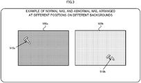
- an abnormal state is a state where the shape of a target is different from the shape of the normal target due to a loss of part of the target or deformation of at least part of the target, and is exemplified by a broken nail 510b illustrated in FIG. 3 .
- FIG. 3 is a diagram illustrating an example of a normal nail and an abnormal nail arranged at different positions on different backgrounds. As illustrated in FIG. 3 , a normal nail 510a and an abnormal nail 510b are arranged on different positions on images 500a and 500b having different backgrounds, respectively.
- description will be made in relation to a scheme that intends to enhance the precision in detecting abnormality of a target in cases where multiple background patterns of a target exist and/or the target may be deformed from its original shape (i.e., in cases where the target is abnormal) due to breaking as exemplarily illustrated in FIG. 3 .
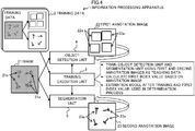
- FIG. 4 is a diagram illustrating an example of a training process among information processing performed by an information processing apparatus 1 according to one embodiment.
- a "target” is assumed to be an object like a nail
- an "image” is assumed to be an image including a target and a background.
- the information processing apparatus 1 may include a training execution unit 3, an object detection unit 4, and a segmentation unit 5 serving as processing functions in a training phase.
- the training execution unit 3 may train an estimation model including the object detection unit 4 and the segmentation unit 5 through executing the following processes (a) to (c).
- the estimation model trained in the above process (b) and the first index value calculated in the above process (c) are used in a determination process that determines, using a trained estimation model, whether or not an target that is included in the target image and that is to be determined is in the normal state.
- FIG. 5 is a diagram illustrating an example of calculating the first index value.
- the training execution unit 3 may calculate a pixel number in the rectangular region 22a included in the first annotation image 22 for each target 21a.
- pixel numbers A-D may be calculated.
- the pixel numbers A-D are examples of an area of each rectangular region 22a in the first annotation image 22.
- the training execution unit 3 may calculate a pixel number of the pixels 23a included in the second annotation image 23 for each target 21a.
- pixel numbers E-H may be calculated.
- the pixel numbers E-H are examples of an area of each pixel 23a in the second annotation image 23.
- the training execution unit 3 may calculate the first index value related to a relationship between the pixel numbers A-D of the rectangular regions 22a and the pixel numbers E-H of the pixels 23a.
- the training execution unit 3 may calculate the first index value for each target 21a. For example, the training execution unit 3 may calculate the first index value between the pixel number A and the pixel number E; the first index value between the pixel number B and the pixel number F; the first index value between the pixel number C and the pixel number G; and the first index value between the pixel number D and the pixel number H.
- the training execution unit 3 may calculate the first index value for each training data 2 included in the data set.
- the relationship for pixel number between the rectangular region 22a including the target 21a and the pixels 23a corresponding to the target 21a can be normalized. This makes it possible to quantatively recognize a correlation value (expected value) between output results from the object detection unit 4 and the segmentation unit 5, both into which the image 21 of the normal target 21a is input, regardless the size of the target 21a in the mage 21.
- FIG. 6 is a diagram illustrating an example of determination process among the information processes by the information processing apparatus 1 according to one embodiment.
- the information processing apparatus 1 may include the trained object detection unit 4, the trained segmentation unit 5, and a determination processing unit 9 for the purpose of a determination process in the determination phase.
- an image 6 is an example of a target image including one or more targets 6a to be determined.
- the image 6 may include an abnormal target 6b such as a broken nail.
- the determination processing unit 9 carries out, based on a second index value on the basis of an output result output from the trained estimation model in response to inputting of the image 6 and the first index value calculated by the training execution unit 3, a determination process that determines whether or not the target 6a included in the image 6 is in the normal state.
- the determination processing unit 9 calculates a second index value related to a relationship between a pixel number corresponding to a rectangular region 7a specified by an estimation result 7 obtained by using the object detection unit 4 and a pixel number of the pixels 8a corresponding to the target 6a specified by an estimation result 8 obtained by using the trained segmentation unit 5.
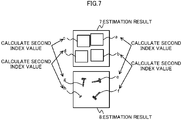
- FIG. 7 is a diagram illustrating an example of calculating the second index value.
- the determination processing unit 9 may calculate the pixel number in the rectangular region 7a included in the estimation result 7 obtained by using the object detection unit 4 for each target 6a, for example.
- the pixel numbers a-d may be calculated.
- the pixel numbers a-d are examples of the area of each rectangular region 7a in the estimation result 7.
- the determination processing unit 9 may calculate a pixel number of the pixels 8a included in the estimation result 8 obtained by using the segmentation unit 5 for each target 6a.
- pixel numbers e-h may be calculated.
- the pixel numbers e-h are examples of an area of each pixel 8a in the estimation result 8.
- the determination processing unit 9 may calculate the second index value related to the relationship between the pixel numbers a-d of the rectangular regions 7a and the pixel numbers e-h of the pixels 8a for each image 6.
- the determination processing unit 9 may calculate the second index value for each target 6a. For example, the determination processing unit 9 may calculate the second index value between the pixel number a and the pixel number e; the second index value between the pixel number b and the pixel number f; the second index value between the pixel number c and the pixel number g; and the second index value between the pixel number d and the pixel number h.
- the relationship between the pixel number of the rectangular region 7a including the target 6a and the pixel number of the pixels 8b corresponding to the target 6a can be normalized. This makes it possible to quantatively recognize a correlation value between output results from the object detection unit 4 and the segmentation unit 5, both into which the image 6 of the normal target 6a is input, regardless the size of the target 6a in the image 6.
- the determination processing unit 9 can determine, based on multiple first index values and the second index value, for example, whether or not the target 6a included in the image 6 is in the normal state.
- the determination process is carried out on the basis of the index values related to relationships between the pixel number related to an estimation result of the object detection unit 4 and the pixel number related to an estimation result of the segmentation unit 5.
- the object detection unit 4 outputs a rectangular region including a target in the input image, and the segmentation unit 5 outputs one or more pixels estimated to correspond to the target in the input image. As the above, the object detection unit 4 and the segmentation unit 5 output an estimation result less effected by the background of the image.
- the information processing apparatus 1 is able to detect possible abnormality (e.g., the target 6b) of the target 6a by discriminating the target 6a and the background of the target 6a included in the image 6 in the determination process based on the first and the second index values.
- possible abnormality e.g., the target 6b
- the object detection unit 4 and the segmentation unit 5 exemplified by YOLO and U-Net, respectively, are not algorithms designed for detecting abnormality of a target, there is low possibility of these units are independently of each other used for the above abnormality detection.
- the information processing apparatus 1 of one embodiment achieves enhancement in precision in detecting abnormality of a target by combining these algorithms with each other and additionally performing the determination process that uses outputs of the both algorithms.
- object-detecting Artificial Intelligence including the object detection unit 4 can output an appropriate rectangular region even if the target is partially lost or deformed.
- the object-detecting AI can robustly detect the target against a change in shape of the target.
- segmentation AI including the segmentation unit 5 is relatively sensitive to a change in shape of a target.
- the segmentation AI is sometimes unable to detect a target in cases where the target is partially lost or deformed because the segmentation AI is trained by using only the targets having a normal shape among targets having normal and abnormal shapes.
- the information processing apparatus 1 of one embodiment can detect abnormality of a target deformed from the original normal shape of the target by utilizing the difference in the ability of estimation between the object detecting AI and the segmentation AI, which have different sensitivities to a target in the abnormal state as the above.
- the information processing apparatus 1 of one embodiment can enhance the precision in detecting abnormality of a target.
- FIG. 8 is a diagram illustrating an example of a normal interventricular septum of a ultrasonographic image
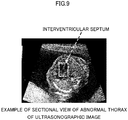
- FIG. 9 is a diagram illustrating an example of an abnormal interventricular septum of a ultrasonographic image. No defect is observed on the interventricular septum in the example of FIG. 8 , but a defect and the resultant deformation are observed on the interventricular septum in the example of FIG. 9 .
- the target is an interventricular septum and an image to be determined is a ultrasonographic image such as an echographic image obtained by photographing a fetus thorax.
- FIG. 10 is a diagram illustrating an example of a functional configuration of a server 10 of one embodiment.
- the server 10 is an example of an apparatus that determines whether or not a target included in the image is in the normal state and is an example of the information processing apparatus 1 illustrated in FIGs. 4-7 .
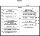
- the server 10 exemplarily includes a memory unit 11, an object detection unit 12, a segmentation unit 13, an acquisition unit 14, a training unit 15, a threshold calculating unit 16, an execution unit 17, a determination unit 18, and an outputting unit 19.
- the memory unit 11 is an example of a storing region and stores various pieces of information to be used for training the object detection unit 12 and the segmentation unit 13, execution (estimation), and outputting. As illustrated in FIG. 10 , the memory unit 11 can exemplarily stores multiple pieces of model information 11a, a training data set 11b, input-data 11c, and output-data 11d.
- the object detection unit 12 is an example of the object detection unit 4 illustrated in FIG. 1 , and for example, specifies a rectangular region including a target in an image in response to inputting of the image.
- An example of the object detection unit 12 may be an object-detecting NNW such as YOLO.
- the segmentation unit 13 is an example of the segmentation unit 5 illustrated in FIG. 1 , and for example, uses one or more pixels estimated to correspond to a target in an image in response to inputting of the image as an output.
- An example of the segmentation unit 13 may be a NNW that carries out segmentation of an image using a machine learning scheme, and is U-Net.
- the segmentation unit 13 is not limited to a U-Net, but may alternatively be a neural network that executes Semantic Segmentation or executes a segmentation scheme except for Semantic Segmentation.
- Information about the network structure and various parameters to achieve the object detection unit 12 and the segmentation unit 13 may be stored as the model information 11a for each of the object detection unit 12 and the segmentation unit 13 in the memory unit 11, for example.
- the acquisition unit 14 acquires information to be used for training and executing an estimation model including the object detection unit 12 and the segmentation unit 13 from, for example, a non-illustrated computer.
- the acquisition unit 14 acquires the training data set 11b to be used for training the estimation model and stores the acquired training data set into the memory unit 11.
- the training data set 11b is an example of a data set including multiple pieces of training data, each piece including an image obtained by photographing a training target, first annotation data representing a rectangular region including the training target in the image, and second annotation data representing one or more pixels corresponding to the training target in the image.
- the training data set 11b may include n (n is an integer of two or more) training data 110 as illustrated in FIG. 11 .
- Each training data 110 may include an image 111 obtained by photographing a training target, a first annotation image 112 representing a rectangular region including the training target in the image 111, and a second annotation image 113 representing one or more pixels corresponding to the training target in the image 111.
- the image 111 may be an echographic image obtained by photographing an interventricular septum serving as an example of a training target as illustrated in FIG. 11 .
- the first annotation image 112 is an example of the first annotation data, and is an image representing an annotation of rectangular information including an interventricular septum included in the image 111 of the training data 110 as illustrated in FIG. 11 .
- the rectangular information may be an image representing a region enclosed by the white dotted-lines in FIG. 11 , for example.
- the second annotation image 113 is an example of the second annotation data, and is an image representing an annotation in a unit of a pixel of an interventricular septum included in the image 111 of the training data 110 as illustrated in FIG. 11 .
- the second annotation image 113 may be an image obtained by masking the interventricular septum included.
- to mask means to display a region to be masked in such a manner that the region can be discriminated from a region not to be masked.
- An example of masking is filling the region to be masked in a predetermined color, in other words, setting a predetermined color to pixels at the region to be masked.
- the masked region i.e., a region corresponding to the interventricular septum
- the region except for the interventricular septum may be filled in black or another color.
- the acquisition unit 14 may acquire input-data 11c to be used for the determination process to be performed by the object detection unit 12 and the segmentation unit 13, and store the acquired input-data 11c into the memory unit 11.
- the input-data 11c is an image set containing one or more images to be determined, which may be a moving image such as a video image including multiple frames.
- the input-data 11c may be echography image including multiple images 114 such as echographic images as illustrated in FIG. 12 .
- the image 114 is an example of a target image to be input into the object detection unit 12 and the segmentation unit 13 in the determination process.
- the training unit 15 is a training execution unit that trains the object detection unit 12 and the segmentation unit 13, and specifically trains the object detection unit 12 and the segmentation unit 13, using the training data set 11b that the acquisition unit 14 acquires.
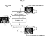
- FIG. 13 is a diagram illustrating an example of a machine learning process performed on the object detection unit 12 and the segmentation unit 13 by the training unit 15. As illustrated in FIG. 13 , the training unit 15 inputs the image 111 including the interventricular septum serving as the target 111a into both the object detection unit 12 and the segmentation unit 13.
- the training unit 15 executes machine learning on the object detection unit 12, using an estimation result that is obtained in response to inputting of the image 111 and that the object detection unit 12 outputs and the first annotation image 112 including annotation of a rectangular region 112a.
- the training unit 15 executes machine learning on the segmentation unit 13, using an estimation result that is obtained in response to inputting of the image 111 and that the segmentation unit 13 outputs and the second annotation image 113 including one or more pixels 113a corresponding to the target 111a.
- the object detection unit 12 is trained so as to specify (output) a rectangular region including the target in the input image likewise the first annotation image 112.
- the segmentation unit 13 is trained so as to output one or more pixels estimated to correspond to the target of the input image likewise the second annotation image 113, in other words, so as to carry out segmentation on the target.
- Any known scheme may be applied to a scheme of machine learning on the estimation model, i.e., the object detection unit 12 and the segmentation unit 13, using the first annotation image 112 and the second annotation image 113 as the teaching data.
- a back propagation may be executed to determine a parameter to be used in a process of the forward propagation.
- a back-propagation may be executed to determine a parameter to be used in a process of the forward propagation.
- an updating process may be carried out to update a variable such as a weight on the basis of a result of the back propagation.
- the parameter and variable may be included in the model information 11a.
- the training unit 15 may update the model information 11a in accordance with execution of the machine learning process.
- the training unit 15 may repeat the machine learning process on each of the object detection unit 12 and the segmentation unit 13, using the multiple training data 110 included in the training data set 11b until the repeat number or the precision reaches the threshold, for example.
- the object detection unit 12 and the segmentation unit 13 that have completed the training are collectively an example of a trained model.
- the threshold calculating unit 16 calculates one of or both the thresholds at an upper limit and a lower limit of a second index value to be detailed below to determine whether or not the target included in the image 114 is in the normal state. For example, the threshold calculating unit 16 may calculate the thresholds in the following procedural steps (i) to (iii).
- the threshold calculating unit 16 calculates the average and the variance of multiple first index value as the target 111a is in a normal state and determines thresholds Th1 and Th2 based on the calculated average and variance.
- the thresholds Th1 and Th2 represent boundaries of a range (e.g., the 2 ⁇ section) where multiple first index values are concentrated. Accordingly, determination of the thresholds Th1 and Th2 makes it possible to easily determine whether or not a second index value to be detailed below is included in a range where multiple first index values are concentrated.
- the threshold calculating unit 16 may alternatively determine the values ( ⁇ - ⁇ ) and ( ⁇ + ⁇ ) to be the lower-limit threshold Th1 and the upper-limit threshold Th2, respectively, by using the first index values at the 1 ⁇ section, i.e., at points distant by ⁇ from the average ⁇ serving as the center of the section.
- the threshold calculating unit 16 may determine the thresholds in accordance with various distributions of the first index values. Alternatively, the threshold calculating unit 16 may calculate the quartiles of the multiple first index values and determine the first quartile and the third quartile to be the lower-limit threshold Th1 and the upper-limit threshold Th2, respectively.
- the execution unit 17 executes an estimation process on the target related to the input-data 11c, using the object detection unit 12 and the segmentation unit 13 (also referred to as the trained object detection unit 12 and the trained segmentation unit 13) that has completed training by the training unit 15.
- FIG. 15 is a diagram illustrating of an example of the estimation process performed by the execution unit 17. As illustrated in FIG. 15 , the execution unit 17 extracts an image 114 included in the input-data 11c in the estimation process.
- the execution unit 17 carries out, in the estimation process, an object detection process by inputting the image 114 into the object detection unit 12 and acquiring a detected image 12a which is the estimation result image output from the object detection unit 12.
- the execution unit 17 carries out, in the estimation process, a segmentation process by inputting the image 114 into the segmentation unit 13 and acquiring a segmentation image 13a which is the estimation result image output from the segmentation unit 13.
- the detected image 12a may include a rectangular region 120a specified by the estimation result acquired by the trained object detection unit 12.
- the rectangular region 120a is a rectangular region 120a corresponding to the target 114a included in the image 114.
- the segmentation image 13a may include one or more pixels 130a corresponding to the target 114a included in the image 114 specified by the estimation result by the trained segmentation unit 13.
- the execution unit 17 may carry out a combination process that generates a combined image 17a by combining the acquired detected image 12a with the acquired segmentation image 13a.
- the combined image 17a may be image data including at least the rectangular region 120a included in the detected image 12a and the pixels 130a included in the segmentation image 13a.
- the background of the combined image 17a may be of mono-color such as solid black as illustrated in FIG. 15 or may be the same as that of the image 114.
- the determination unit 18 executes a determination process that determines whether or not the target 114a included in the image 114 is in the normal state on the basis of a set of the detected image 12a and the segmentation image 13a or a set of the rectangular region 120a and the pixels 130a included in the combined image 17a.
- the determination unit 18 calculates a second index value related to a relationship between a pixel number corresponding to a rectangular region 120a and a pixel number of the pixels 130a corresponding to the target 114a in the output result from the trained estimation model in response to inputting of the image 114 including the target 114a to be determined.
- the second index value may be, for example, a ratio between the pixel number corresponding to the rectangular region 120a specified by the estimation result obtained by using the object detection unit 12 and the pixel number of the pixels 130a corresponding to the target 114a specified by the estimation result obtained by using the segmentation unit 13.
- the determination unit 18 calculates, as the second index value, a ratio of the pixel number of the pixel 130a (see FIG. 15 ) of the combined image 17a or the segmentation image 13a to the rectangular region 120a (see FIG. 15 ) of the combined image 17a or the detected image 12a.
- the determination unit 18 is an example of a second index value calculation unit.
- the determination unit 18 may calculate the second index value for each of multiple images 114 included in the input-data 11c and also for each of one or more targets 114a included in each image 114.
- the determination unit 18 may determine whether or not the target 114a included in the image 114 is in the normal state on the basis of the calculated second index value and the first index value that the threshold calculating unit 16 calculates. For example, the determination unit 18 may determine normality or abnormality of the target 114a by comparing the second index value with the thresholds Th1 and Th2 determined on the basis of the first index value.
- the determination unit 18 may determine that the target 114a is in the normal state when the calculated second index value is equal to or more than the lower-limit threshold Th1 and also equal or less than the upper-limit threshold Th2, as illustrated in FIG. 15 .
- the determination unit 18 may determine that the target 114a is in the abnormal state when the calculated second index value is more than the upper-limit threshold Th2 or less than the lower-limit threshold Th1 as illustrated in FIG. 16 .
- the determination unit 18 can easily determine whether or not the target 114a is in the normal state by comparing the second index value with the threshold Th1 and/or the threshold Th2.
- the outputting unit 19 may output (accumulate) the combined images 17a input from the execution unit 17 and/or the detected images 12a and the segmentation images 13a to (into) the memory unit 11 and generate the output-data 11d based on the multiple accumulated images.
- the output-data 11d may be an image set composed of one or more output images 115 each including one of or the both the rectangular region 120a and the pixels 130a.
- the output image 115 may be the combined image 17a and/or a set of the detected image 12a and the segmentation image 13a, for example.
- Another example of the output image 115 may be a moving image such as a video image including multiple frames.
- the output-data 11d may be a video image in which the output images 115 serving as the combined images 17a are chronologically combined as frames, as illustrated in FIG. 17 .
- the outputting unit 19 may output the determination result by the determination unit 18 which result is exemplified by whether the target 114a is in the normal state or the abnormal state.
- the determination result may be displayed in the output image 115 or may be output data independent from the output image 115, for example.
- the outputting unit 19 overlays the display of a message 116 indicating the abnormal state on the output image 115.
- the outputting unit 19 may transmit the output-data 11d to a non-illustrated computer, for example.
- the execution unit 17, the determination unit 18, and the outputting unit 19 collectively serve as an example of a determination processing unit that executes a determination process that determines, using the trained estimation model, whether or not the target 114a included in the image 114 is in the normal state.
- the execution unit 17, the determination unit 18, and the outputting unit 19 collectively serving as an example of a determination processing unit may execute the determination process and output the determination result.
- FIG. 18 is a flow diagram illustrating an example of operation performed by the object detection unit 12 and the segmentation unit 13 in a training phase.
- the acquisition unit 14 acquires the training data set 11b (Step S1) and stores the training data set 11b into the memory unit 11.
- the training unit 15 inputs an image 111 included in each training data 110 of the training data set 11b into the object detection unit 12 and the segmentation unit 13 and executes machine learning (Step S2).
- the training unit 15 gives the first annotation image 112, as teaching data, to the object detection unit 12 and also gives the second annotation image 113, as teaching data, to the segmentation unit 13.
- the training unit 15 executes the machine learning on each of the object detection unit 12 and segmentation unit 13, using the multiple training data 110 in the training data set 11b.
- the threshold calculating unit 16 calculates multiple first index values based on the first and second annotation images 112 and 113 in the training data set 11b (Step S3).
- the threshold calculating unit 16 calculates the lower-limit threshold Th1 and the upper-limit threshold Th2 based on the multiple first index values (step S4) and terminates the process.
- FIG. 19 is a flow diagram illustrating an example of operation performed by the object detection unit 12 and the segmentation unit 13 in a determination phase.
- the acquisition unit 14 acquires the input-data 11c (Step S11) and stores the input-data 11c into the memory unit 11.
- the execution unit 17 inputs an image 114 included in the input-data 11c into the object detection unit 12 and the segmentation unit 13 (Step S12).
- the execution unit 17 generates a combined image 17a by combining the detected image 12a output from the object detection unit 12 and the segmentation image 13a output from the segmentation unit 13.
- the determination unit 18 calculates the second index value based on the pixel number of the rectangular region 120a in the detected image 12a and the pixel number of the pixels 130a corresponding to the target 114a included in the segmentation image 13a (Step S13).
- the determination unit 18 determines, based on the second index value and the lower-limit threshold Th1 and the upper-limit threshold Th2 that the threshold calculating unit 16 calculates, whether the target 114a is in the normal state or the abnormal state (Step S14).
- the outputting unit 19 accumulates the combined images 17a, as the output images 115, and outputs the output-data 11d obtained by merging the output images 115 being accumulated and the determination result made by the determination unit 18 (Step S15), and terminates the process.
- the output destination of the output-data 11d may be a non-illustrated computer or the like in addition to or in replace of the memory unit 11.
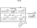
- FIG. 20 is a block diagram schematically illustrating an example of the HW configuration of a computer 20 that achieves the functions of the information processing apparatus 1 and the sever 10.
- each of the computers may have the HW configuration exemplarily illustrated in FIG. 20 .
- the computer 20 may exemplarily include a processor 20a, a memory 20b, a storing device 20c, an IF (Interface) device 20d, an I/O (Input/Output) device 20e, and a reader 20f as the HW configuration.
- the processor 20a is an example of an arithmetic processing apparatus that performs various controls and arithmetic operations.
- the processor 20a may be communicably connected to the blocks in the computer 20 to each other via a bus 20i.
- the processor 20a may be a multiprocessor including multiple processors, or a multi-core processor having multiple processor cores, or have a configuration consisting of multiple multi-core processors.
- processor 20a integrated circuits such as, for example, a CPU, an MPU, a GPU, an APU, a DSP, an ASIC and an FPGA are available. It is to be noted that, as the processor 20a, a combination of two or more of such integrated circuits as mentioned above may be used.
- the processing functions of at least part of the information processing apparatus 1, at least some of the acquisition unit 14, the threshold calculating unit 16, and the execution unit 17 of the server 10, the determination unit 18, and the outputting unit 19 may be achieved by a CPU or an MPU serving as the processor 20a.
- the processing functions of at least part of the information processing apparatus 1, at least some of the object detection unit 12, the segmentation unit 13, and the training unit 15 of the server 10, and the execution unit 17 may be achieved by an accelerator such as a GPU or ASIC (e.g., a Tensor Processing Unit (TPU)) in the processor 20a.
- TPU Tensor Processing Unit
- CPU is an abbreviation of Central Processing Unit
- MPU is an abbreviation of Micro Processing Unit
- GPU is an abbreviation of Graphics Processing Unit
- APU is an abbreviation of Accelerated Processing Unit
- DSP is an abbreviation of Digital Signal Processor
- ASIC is an abbreviation of Application Specific IC
- FPGA is an abbreviation of Field-Programmable Gate Array.
- TPU is an abbreviation of Tensor Processing Unit.
- the memory 20b is an example of a HW device that stores information such as various data pieces and a program.
- An example of the memory 20b includes one of or both a volatile memory such as the Dynamic Random Access Memory (DRAM), and a non-volatile memory such as the Persistent Memory (PM).
- DRAM Dynamic Random Access Memory
- PM Persistent Memory
- the storing device 20c is an example of a HW device that stores various data and a program.
- Examples of the storing device 20c is various storing devices exemplified by a magnetic disk device such as a Hard Disk Drive (HDD), a semiconductor drive device such as an Solid State Drive (SSD), and a non-volatile memory.
- Examples of a non-volatile memory are a flash memory, a Storage Class Memory (SCM) and a Read Only Memory (ROM).
- the storing device 20c may store a program 20g (information processing program) that achieves all or part of the functions of the computer 20.
- the processor 20a of the information processing apparatus 1 expands the program 20g stored in the storing device 20c onto the memory 20b and executes the expanded program 20g, so that the function as the information processing apparatus 1 illustrated in FIGs. 4 and 6 can be achieved.
- the processor 20a of the server 10 expands the program 20g stored in the storing device 20c onto the memory 20b and executes the expanded program 20g, so that the function as the server 10 illustrated in FIG. 10 can be achieved.
- a storing region possessed by at least one of the memory 20b and the storing device 20c may store the various pieces of the information 11a-11d illustrated in FIG. 10 .
- the memory unit 11 of FIG. 10 may be achieved by the storing region possessed by at least one of the memory 20b and the storing device 20c.
- the IF device 20d is an example of a communication IF that controls connection to and communication with a network.
- the IF device 20d may include an adaptor compatible with a LAN such as Ethernet (registered trademark) or an optical communication such as Fibre Channel (FC).
- the adaptor may be compatible with one of or both wired and wireless communication schemes.
- the server 10 may be communicably connected to another device via the IF device 20d.
- the program 20g may be downloaded from a network to a computer 20 through the communication IF and then stored into the storing device 20c.
- the I/O device 20e may include one of or both an input device and an output device.
- Examples of the input device are a keyboard, a mouse, and a touch screen.
- Examples of the output device are a monitor, a projector, and a printer.
- the reader 20f is an example of a reader that reads information of data and programs recorded on a recording medium 20h.
- the reader 20f may include a connecting terminal or a device to which the recording medium 20h can be connected or inserted.
- Examples of the reader 20f include an adapter conforming to, for example, Universal Serial Bus (USB), a drive apparatus that accesses a recording disk, and a card reader that accesses a flash memory such as an SD card.
- the program 20g may be stored in the recording medium 20h.
- the reader 20f may read the program 20g from the recording medium 20h and store the read program 20g into the storing device 20c.
- An example of the recording medium 20h is a non-transitory computer-readable recording medium such as a magnetic/optical disk, and a flash memory.
- the magnetic/optical disk include a flexible disk, a Compact Disc (CD), a Digital Versatile Disc (DVD), a Blu-ray disk, and a Holographic Versatile Disc (HVD).
- the flash memory include a semiconductor memory such as a USB memory and an SD card.
- the HW configuration of the computer 20 described above is merely illustrative. Accordingly, the computer 20 may appropriately undergo increase or decrease of HW (e.g., addition or deletion of arbitrary blocks), division, integration in an arbitrary combination, and addition or deletion of the bus. For example, at least one of the I/O device 20e and the reader 20f may be omitted in the information processing apparatus 1 and the sever 10.
- processing functions 12-19 that the server 10 of FIG. 10 includes may be merged in an arbitrary combination and each may be divided.
- the above one embodiment assumes the target and the image to be an interventricular septum and an echographic image, respectively, but the target and the image are not limited to these examples.
- the scheme according to the one embodiment can be applied to various targets and images as follows.
- Example of the target is a part of a human body and various articles having shapes to be deformed.
- Examples of the image is various images obtained by photographing a region including the target. Examples of the image include a ultrasonographic image except for an echographic image, a magnetic resonance image, an X-ray image, an image detected by a sensor that captures temperature or electromagnetic image, and an image photographed by an imaging sensor that captures visible light or invisible light.
- the server 10 illustrated in FIG. 10 may have a configuration that achieves various processing function by uniting multiple devices via a network.
- the acquisition unit 14 and the outputting unit 19 may be one or more Web servers
- the object detection unit 12, the segmentation unit 13, the training unit 15, the threshold calculating unit 16, the execution unit 17, and the determination unit 18 may be one or more application servers
- the memory unit 11 may be a Database (DB) server.
- each processing function as the server 10 may be achieved by uniting the Web servers, the application servers, and the DB server via a network.
- processing function i.e., the object detection unit 12, the segmentation unit 13, the acquisition unit 14, and the training unit 15
- the processing function i.e., the execution unit 17, the determination unit 18, and the outputting unit 19
- each processing function as the server 10 may be achieved by uniting these devices via a network.
Landscapes
- Engineering & Computer Science (AREA)
- Theoretical Computer Science (AREA)
- Physics & Mathematics (AREA)
- General Physics & Mathematics (AREA)
- Evolutionary Computation (AREA)
- Health & Medical Sciences (AREA)
- General Health & Medical Sciences (AREA)
- Artificial Intelligence (AREA)
- Computer Vision & Pattern Recognition (AREA)
- Computing Systems (AREA)
- Software Systems (AREA)
- Life Sciences & Earth Sciences (AREA)
- Multimedia (AREA)
- Data Mining & Analysis (AREA)
- Biomedical Technology (AREA)
- Molecular Biology (AREA)
- Medical Informatics (AREA)
- General Engineering & Computer Science (AREA)
- Databases & Information Systems (AREA)
- Biophysics (AREA)
- Computational Linguistics (AREA)
- Mathematical Physics (AREA)
- Biodiversity & Conservation Biology (AREA)
- Radiology & Medical Imaging (AREA)
- Quality & Reliability (AREA)
- Nuclear Medicine, Radiotherapy & Molecular Imaging (AREA)
- Bioinformatics & Cheminformatics (AREA)
- Bioinformatics & Computational Biology (AREA)
- Evolutionary Biology (AREA)
- Image Analysis (AREA)
Abstract
Description
- The embodiments discussed herein relates to an information processing program, a method for processing information, and an information processing apparatus.
- As a scheme for detecting abnormality of a target included in an input image, a scheme for detecting abnormality with an auto-encoder has been known.
- In a scheme for detecting abnormality with an auto-encoder, the auto-encoder is trained, using normal data in which a target is normal as an input, so as to reconstruct the normal data and output the decoded the normal data.
- Since, even if abnormal data in which the target is abnormal is input, a trained auto-encoder decodes the abnormal data to normal data, the difference between the input-data and the output-data in this case is larger than that of cases where normal data is input.
- For its ability of detecting abnormality of a target on the basis of a deviation of abnormal data from the normal data as a result of training that uses only the normal data among the normal and abnormal data, the scheme for detecting abnormality using an auto-encoder is highly versatile.
- [Non-Patent Document 1] Simon Hawkins et al., "Outlier Detection Using Replicator Neural Networks", "Data Warehousing and Knowledge Discovery: 4th International Conference", September 2, 2002
- In the meantime, such a scheme for detecting abnormality using an auto-encoder sometimes has a difficulty in discriminating the background and noise included in the normal data from abnormality, and therefore is sometimes vulnerable to change of the background and noise.
- For the above, when the above scheme for detecting abnormality in the target is applied to abnormality detection of a target, which has variations in at least of the position and the background thereof, the precision in detecting abnormality may be lowered.
- As one aspect, one of the objects of the present invention is to enhance the precision in detecting abnormality of a target.
- According to an aspect of the embodiments, an information processing program that causes a computer to execute a process including: acquiring a training data set including a plurality of pieces of training data, each of the plurality pieces of training data including an image obtained by photographing a training target, first annotation data representing a rectangular region including the training target in the image, and second annotation data representing one or more pixels corresponding to the training target in the image; training, based on the image and the first annotation data included in the training data set, an object detection model included in an estimation model, the object detection model specifying a rectangular region including the training target in the image in response to inputting of the image; training, based on the image and the second annotation data included in the training data set, a neural network included in the estimation model, the neural network outputs one or more pixels estimated to correspond to the training target in the image in response to inputting of the image; and calculating a first index value related to a relationship of a pixel number between a pixel number of the rectangular region including the training target specified by the first annotation data and a pixel number corresponding to the training target specified by the second annotation data, the estimation model after the training and the calculated first index value being used in a determination process that determines, based on the calculated first index value and a second index value, whether or not a target that is to be determined and that is included in a target image is normal, the second index value being related to a relationship between a pixel number corresponding to a rectangular region specified by an estimation result obtained by using the trained object detection model in an output result and a pixel number corresponding to the target specified by an estimation result obtained by using the trained neural network, the output result being output from the estimation model after the training in response to inputting of the target image including the target.
- As one aspect, the precision in detecting abnormality of a target can be enhanced.
-
-
FIG. 1 is a diagram illustrating an abnormality detection process according to a first scheme of a comparative example; -
FIG. 2 is a diagram illustrating an abnormality detection process according to a second scheme of a comparative example; -
FIG. 3 is a diagram illustrating an example of normal nail and abnormal nail arranged at different positions on different backgrounds; -
FIG. 4 is a diagram illustrating an example of a training process by an information processing apparatus according to one embodiment; -
FIG. 5 is a diagram illustrating an example of calculating a first index value; -
FIG. 6 is a diagram illustrating an example of a determination process by the information processing apparatus according to one embodiment; -
FIG. 7 is a diagram illustrating an example of calculating a second index value; -
FIG. 8 is a diagram illustrating an example of a normal interventricular septum of a ultrasonographic image; -
FIG. 9 is a diagram illustrating an example of an abnormal interventricular septum of a ultrasonographic image; -
FIG. 10 is a block diagram illustrating an example of a functional configuration of a server according to one embodiment; -
FIG. 11 is a diagram illustrating an example of a training data set; -
FIG. 12 is a diagram illustrating an example of input-data; -
FIG. 13 is a diagram illustrating an example of a machine learning process on an object detection unit and a segmentation unit by a training unit; -
FIG. 14 is a diagram illustrating an example a determination process of upper-limit and lower-limit thresholds by a threshold calculation unit; -
FIG. 15 is a diagram illustrating of an example of an estimation process by an execution unit; -
FIG. 16 is a diagram illustrating of an example of an estimation process by the execution unit; -
FIG. 17 is a diagram illustrating an example of output-data; -
FIG. 18 is a flow diagram illustrating an example of operation in a training phase; -
FIG. 19 is a flow diagram illustrating an example of operation in a determination phase; and -
FIG. 20 is a block diagram schematically illustrating an example of the hardware configuration of a computer of one embodiment. - Hereinafter, an embodiment of the present invention will now be described with reference to the accompanying drawings. However, one embodiment described below is merely illustrative and the present embodiment can be variously modified and implemented without departing from the scope thereof. In the drawings to be used in the following description, the same reference numbers denote the same or similar parts, unless otherwise specified.
- First of all, description will now be made in relation to a comparative example to one embodiment.
FIGs. 1 and2 are each diagram illustrating an abnormal detection process of the comparative example. - As illustrated in
FIG. 1 , according to the first scheme of the comparative example, a server carries out unsupervised training by inputting animage 210 including a target into an auto-encoder 100 and instructing the auto-encoder 100 to output animage 220 obtained by reconstructing (decoding) theimage 210 in a training phase. - In a working phase after the training phase, the sever compares an
input image 230 with anoutput image 240 output from the auto-encoder 100 using theinput image 230 as the input to obtain a difference between theinput image 230 and theoutput image 240 and, if the difference is large, determines that the target included in theinput image 230 is abnormal. - For example, since the difference between an
input image 231 including a target having a normal value and anoutput image 241 based on theinput image 231 is relatively small, the server determines that the target included in theinput image 231 to be normal. On the other hand, since the difference between aninput image 232 including a target having an abnormal value and anoutput image 242 based on theinput image 232 is relatively large, the server determines that the target included in theinput image 232 to be abnormal. - However, even if wishing to determine normality or abnormality of only the target included in the
input mage 230, the first scheme of the comparative example has a possibility of detecting variation of the background and/or the position included in theimage 230, i.e., noise, to be abnormal, which results in lowering the precision of detecting abnormality. - A second scheme illustrated in
FIG. 2 is conceivable for an improvement to the first scheme, for example. As illustrated inFIG. 2 , the second scheme of the comparative example detects a mask of an object (target) to be examined from an input image in a unit of pixel, using a trained neural network (NNW) 300 for segmentation which network is trained with normal data. Then the server determines whether or not the target, which is masked, is normal or abnormal by applying the first scheme to the mask of the object to be examined which mask is detected in a unit of pixel. - For example, the server obtains a
mask image 420 being output from the NNW 300 that inputs animage 410 including the target and including a mask of the target in a training phase. Then the sever carries out unsupervised training on the auto-encoder 100 such that the auto-encoder 100 reconstructs theinput mask image 420 and outputs anoutput mask image 430. - Further, in the working phase after the training phase, the sever compares the
mask image 450 output from the NNW 300 using theimage 440 as an input with anoutput mask image 460 output from the auto-encoder 100 using themask image 450 as the input to obtain a difference. - For example, since the differences of
mask images output mask images images mask image 453 including a target having an abnormal value from a correspondingoutput mask image 463 is relatively large, the server determines that the target included in animage 443 to be abnormal. - Here, in the second scheme of the comparative example, the NNW 300 for segmentation preferentially learns normal data having a larger data volume. Accordingly, in cases where an
image 444 including an abnormal target is input as represented by a dot-line frame 470 illustrated inFIG. 2 , a mask of a target is sometimes not output to amask image 454 output from the NNW 300, which means themask image 454 in which nothing appears may be output. - However, since the auto-
encoder 100 may learn the image in which nothing appears to be normal, the difference between themask image 454 and theoutput mask image 464 output from the trained auto-encoder 100 is sometimes relatively small. In this case, the server does not sometimes detect the abnormality like the target included in theimage 444. - "Abnormality" of a target may mean that, for example, the target has a shape different from the original shape of the normal target to an extent that the trained
NNW 300 fails to detect the target to be a segmentation target. For example, such an abnormal state is a state where the shape of a target is different from the shape of the normal target due to a loss of part of the target or deformation of at least part of the target, and is exemplified by abroken nail 510b illustrated inFIG. 3 . -
FIG. 3 is a diagram illustrating an example of a normal nail and an abnormal nail arranged at different positions on different backgrounds. As illustrated inFIG. 3 , anormal nail 510a and anabnormal nail 510b are arranged on different positions onimages - In one embodiment, description will be made in relation to a scheme that intends to enhance the precision in detecting abnormality of a target in cases where multiple background patterns of a target exist and/or the target may be deformed from its original shape (i.e., in cases where the target is abnormal) due to breaking as exemplarily illustrated in
FIG. 3 . -
FIG. 4 is a diagram illustrating an example of a training process among information processing performed by aninformation processing apparatus 1 according to one embodiment. In the following description, a "target" is assumed to be an object like a nail, and an "image" is assumed to be an image including a target and a background. - As illustrated in
FIG. 4 , theinformation processing apparatus 1 may include a training execution unit 3, anobject detection unit 4, and asegmentation unit 5 serving as processing functions in a training phase. - The training execution unit 3 may train an estimation model including the
object detection unit 4 and thesegmentation unit 5 through executing the following processes (a) to (c). - (a) The training execution unit 3 acquires a data set including
multiple training data 2.
Thetraining data 2 may include animage 21, afirst annotation image 22, and asecond annotation image 23.
Theimage 21 is an example of an image obtained by photographing a training target, and may include one ormore targets 21a to be learned. Theobject 21a may be a normal object, for example. Thefirst annotation image 22 is an example of first annotation data and is an image representing arectangular region 22a including thetarget 21a in theimage 21. Thesecond annotation image 23 is an example of second annotation data and is an image representing one ormore pixels 23a corresponding to thetarget 21a in theimage 21. - (b) The training execution unit 3 trains the
object detection unit 4 on the basis of theimage 21 in the data set and thefirst annotation image 22, and trains thesegmentation unit 5 on the basis of theimage 21 in the data set and thesecond annotation image 23.
Theobject detection unit 4 is an example of an object detection model, and specifies the rectangular region including thetarget 21a in theimage 21 in response to inputting of theimage 21. Examples of theobject detection unit 4 are various NNWs for object detection, and theobject detection unit 4 is assumed to be YOLO in one embodiment, for example.
Thesegmentation unit 5 is an example of a NNW and uses one or more pixels estimated to correspond to thetarget 21a in theimage 21 in response to an input as an output. Examples of thesegmentation unit 5 are various NNWs for segmentation, and thesegmentation unit 5 is assumed to a U-Net in one embodiment. Thesegmentation unit 5 is not limited to a U-Net, but may alternatively be a neural network that executes Semantic Segmentation or executes a segmentation scheme except for Semantic Segmentation.
For example, the training execution unit 3 may input theimage 21 into theobject detection unit 4 for eachtraining data 2 included in the data set and carry out machine learning on theobject detection unit 4, using thefirst annotation image 22 as teaching data. In addition, the training execution unit 3 may input theimage 21 into thesegmentation unit 5 for eachtraining data 2 included in the data set and carry out machine learning on thesegmentation unit 5, using thesecond annotation image 23 as teaching data. - (c) The training execution unit 3 calculates a first index value related to a relationship between a pixel number corresponding to a
rectangular region 22a including thetarget 21a specified by thefirst annotation image 22 and the number (pixel number) ofpixels 23a corresponding to thetarget 21a specified by thesecond annotation image 23. - The estimation model trained in the above process (b) and the first index value calculated in the above process (c) are used in a determination process that determines, using a trained estimation model, whether or not an target that is included in the target image and that is to be determined is in the normal state.
-
FIG. 5 is a diagram illustrating an example of calculating the first index value. For example, the training execution unit 3 may calculate a pixel number in therectangular region 22a included in thefirst annotation image 22 for eachtarget 21a. In the example ofFIG. 5 , pixel numbers A-D may be calculated. The pixel numbers A-D are examples of an area of eachrectangular region 22a in thefirst annotation image 22. - For example, the training execution unit 3 may calculate a pixel number of the
pixels 23a included in thesecond annotation image 23 for eachtarget 21a. In the example ofFIG. 5 , pixel numbers E-H may be calculated. The pixel numbers E-H are examples of an area of eachpixel 23a in thesecond annotation image 23. - Then the training execution unit 3 may calculate the first index value related to a relationship between the pixel numbers A-D of the
rectangular regions 22a and the pixel numbers E-H of thepixels 23a. - Alternatively, the training execution unit 3 may calculate the first index value for each
target 21a. For example, the training execution unit 3 may calculate the first index value between the pixel number A and the pixel number E; the first index value between the pixel number B and the pixel number F; the first index value between the pixel number C and the pixel number G; and the first index value between the pixel number D and the pixel number H. - Further alternatively, the training execution unit 3 may calculate the first index value for each
training data 2 included in the data set. - By calculating the first index value as the above, the relationship for pixel number between the
rectangular region 22a including thetarget 21a and thepixels 23a corresponding to thetarget 21a can be normalized. This makes it possible to quantatively recognize a correlation value (expected value) between output results from theobject detection unit 4 and thesegmentation unit 5, both into which theimage 21 of thenormal target 21a is input, regardless the size of thetarget 21a in themage 21. -
FIG. 6 is a diagram illustrating an example of determination process among the information processes by theinformation processing apparatus 1 according to one embodiment. - As illustrated in
FIG. 6 , theinformation processing apparatus 1 may include the trainedobject detection unit 4, the trainedsegmentation unit 5, and adetermination processing unit 9 for the purpose of a determination process in the determination phase. - As illustrated in
FIG. 6 , animage 6 is an example of a target image including one ormore targets 6a to be determined. Theimage 6 may include anabnormal target 6b such as a broken nail. - The
determination processing unit 9 carries out, based on a second index value on the basis of an output result output from the trained estimation model in response to inputting of theimage 6 and the first index value calculated by the training execution unit 3, a determination process that determines whether or not thetarget 6a included in theimage 6 is in the normal state. - For example, the
determination processing unit 9 calculates a second index value related to a relationship between a pixel number corresponding to arectangular region 7a specified by anestimation result 7 obtained by using theobject detection unit 4 and a pixel number of thepixels 8a corresponding to thetarget 6a specified by anestimation result 8 obtained by using the trainedsegmentation unit 5. -
FIG. 7 is a diagram illustrating an example of calculating the second index value. Thedetermination processing unit 9 may calculate the pixel number in therectangular region 7a included in theestimation result 7 obtained by using theobject detection unit 4 for eachtarget 6a, for example. In the example ofFIG. 7 , the pixel numbers a-d may be calculated. The pixel numbers a-d are examples of the area of eachrectangular region 7a in theestimation result 7. - For example, the
determination processing unit 9 may calculate a pixel number of thepixels 8a included in theestimation result 8 obtained by using thesegmentation unit 5 for eachtarget 6a. In the example ofFIG. 7 , pixel numbers e-h may be calculated. The pixel numbers e-h are examples of an area of eachpixel 8a in theestimation result 8. - Then the
determination processing unit 9 may calculate the second index value related to the relationship between the pixel numbers a-d of therectangular regions 7a and the pixel numbers e-h of thepixels 8a for eachimage 6. - Alternatively, the
determination processing unit 9 may calculate the second index value for eachtarget 6a. For example, thedetermination processing unit 9 may calculate the second index value between the pixel number a and the pixel number e; the second index value between the pixel number b and the pixel number f; the second index value between the pixel number c and the pixel number g; and the second index value between the pixel number d and the pixel number h. - By calculating the second index value as the above, the relationship between the pixel number of the
rectangular region 7a including thetarget 6a and the pixel number of thepixels 8b corresponding to thetarget 6a can be normalized. This makes it possible to quantatively recognize a correlation value between output results from theobject detection unit 4 and thesegmentation unit 5, both into which theimage 6 of thenormal target 6a is input, regardless the size of thetarget 6a in theimage 6. - This makes it possible to derive a significant difference between the correlation value (expected value) when the
image 21 of thenormal target 21a is input and the correlation value when theimage 6 of theabnormal target 6b is input in regard of the output results from theobject detection unit 4 and thesegmentation unit 5. - Accordingly, the
determination processing unit 9 can determine, based on multiple first index values and the second index value, for example, whether or not thetarget 6a included in theimage 6 is in the normal state. - An example of the determination logic based on the first and the second index values will be detailed below.
- As described above, according to the
information processing apparatus 1 of one embodiment, the determination process is carried out on the basis of the index values related to relationships between the pixel number related to an estimation result of theobject detection unit 4 and the pixel number related to an estimation result of thesegmentation unit 5. - The
object detection unit 4 outputs a rectangular region including a target in the input image, and thesegmentation unit 5 outputs one or more pixels estimated to correspond to the target in the input image. As the above, theobject detection unit 4 and thesegmentation unit 5 output an estimation result less effected by the background of the image. - Accordingly, the
information processing apparatus 1 is able to detect possible abnormality (e.g., thetarget 6b) of thetarget 6a by discriminating thetarget 6a and the background of thetarget 6a included in theimage 6 in the determination process based on the first and the second index values. - Since the
object detection unit 4 and thesegmentation unit 5 exemplified by YOLO and U-Net, respectively, are not algorithms designed for detecting abnormality of a target, there is low possibility of these units are independently of each other used for the above abnormality detection. In contrast to the above, theinformation processing apparatus 1 of one embodiment achieves enhancement in precision in detecting abnormality of a target by combining these algorithms with each other and additionally performing the determination process that uses outputs of the both algorithms. - For example, object-detecting Artificial Intelligence (AI) including the
object detection unit 4 can output an appropriate rectangular region even if the target is partially lost or deformed. In other words, the object-detecting AI can robustly detect the target against a change in shape of the target. - In contrast, segmentation AI including the
segmentation unit 5 is relatively sensitive to a change in shape of a target. For example, the segmentation AI is sometimes unable to detect a target in cases where the target is partially lost or deformed because the segmentation AI is trained by using only the targets having a normal shape among targets having normal and abnormal shapes. - The
information processing apparatus 1 of one embodiment can detect abnormality of a target deformed from the original normal shape of the target by utilizing the difference in the ability of estimation between the object detecting AI and the segmentation AI, which have different sensitivities to a target in the abnormal state as the above. - As described above, the
information processing apparatus 1 of one embodiment can enhance the precision in detecting abnormality of a target. - The following description will now be made in relation to a case where the determination process by the
information processing apparatus 1 is applied to abnormality detection of a part called the interventricular septum of a fetus heart in ultrasonographic diagnosis. - It is important for ultrasonographic check of a fetus heart to determine the presence or the absence of a defect in interventricular septum.
FIG. 8 is a diagram illustrating an example of a normal interventricular septum of a ultrasonographic image; andFIG. 9 is a diagram illustrating an example of an abnormal interventricular septum of a ultrasonographic image. No defect is observed on the interventricular septum in the example ofFIG. 8 , but a defect and the resultant deformation are observed on the interventricular septum in the example ofFIG. 9 . - In detecting a defect on the interventricular septum illustrated in
FIG. 9 , at least one of the following inconvenience (A)-(C) may occur. - (A) A ultrasonographic image sometimes contains much noise, which may be detected to be abnormality of the interventricular septum.
- (B) The position of the interventricular septum in the ultrasonographic image is changed with the operation of the probe.
- (C) When the interventricular septum has a defect, the shape of the interventricular septum are largely deformed.
- Hereinafter, description will now be made in relation to an example of a case where the
information processing apparatus 1 solves the above inconvenience. The following description assumes that the target is an interventricular septum and an image to be determined is a ultrasonographic image such as an echographic image obtained by photographing a fetus thorax. -
FIG. 10 is a diagram illustrating an example of a functional configuration of aserver 10 of one embodiment. Theserver 10 is an example of an apparatus that determines whether or not a target included in the image is in the normal state and is an example of theinformation processing apparatus 1 illustrated inFIGs. 4-7 . - As illustrated in
FIG. 10 , theserver 10 exemplarily includes amemory unit 11, anobject detection unit 12, asegmentation unit 13, anacquisition unit 14, atraining unit 15, athreshold calculating unit 16, anexecution unit 17, adetermination unit 18, and anoutputting unit 19. - The
memory unit 11 is an example of a storing region and stores various pieces of information to be used for training theobject detection unit 12 and thesegmentation unit 13, execution (estimation), and outputting. As illustrated inFIG. 10 , thememory unit 11 can exemplarily stores multiple pieces ofmodel information 11a, atraining data set 11b, input-data 11c, and output-data 11d. - The
object detection unit 12 is an example of theobject detection unit 4 illustrated inFIG. 1 , and for example, specifies a rectangular region including a target in an image in response to inputting of the image. An example of theobject detection unit 12 may be an object-detecting NNW such as YOLO. - The
segmentation unit 13 is an example of thesegmentation unit 5 illustrated inFIG. 1 , and for example, uses one or more pixels estimated to correspond to a target in an image in response to inputting of the image as an output. An example of thesegmentation unit 13 may be a NNW that carries out segmentation of an image using a machine learning scheme, and is U-Net. Thesegmentation unit 13 is not limited to a U-Net, but may alternatively be a neural network that executes Semantic Segmentation or executes a segmentation scheme except for Semantic Segmentation. Information about the network structure and various parameters to achieve theobject detection unit 12 and thesegmentation unit 13 may be stored as themodel information 11a for each of theobject detection unit 12 and thesegmentation unit 13 in thememory unit 11, for example. - The
acquisition unit 14 acquires information to be used for training and executing an estimation model including theobject detection unit 12 and thesegmentation unit 13 from, for example, a non-illustrated computer. - For example, the
acquisition unit 14 acquires thetraining data set 11b to be used for training the estimation model and stores the acquired training data set into thememory unit 11. - The
training data set 11b is an example of a data set including multiple pieces of training data, each piece including an image obtained by photographing a training target, first annotation data representing a rectangular region including the training target in the image, and second annotation data representing one or more pixels corresponding to the training target in the image. - For example, the
training data set 11b may include n (n is an integer of two or more)training data 110 as illustrated inFIG. 11 . Eachtraining data 110 may include animage 111 obtained by photographing a training target, afirst annotation image 112 representing a rectangular region including the training target in theimage 111, and asecond annotation image 113 representing one or more pixels corresponding to the training target in theimage 111. - For example, the
image 111 may be an echographic image obtained by photographing an interventricular septum serving as an example of a training target as illustrated inFIG. 11 . The echographic images ofmultiple training data 110 may be frames chronologically (e.g., t=0 to (n-1)) extracted from a series of echographic images, frames extracted from different moving images, or images photographed as still images. - The
first annotation image 112 is an example of the first annotation data, and is an image representing an annotation of rectangular information including an interventricular septum included in theimage 111 of thetraining data 110 as illustrated inFIG. 11 . The rectangular information may be an image representing a region enclosed by the white dotted-lines inFIG. 11 , for example. - The
second annotation image 113 is an example of the second annotation data, and is an image representing an annotation in a unit of a pixel of an interventricular septum included in theimage 111 of thetraining data 110 as illustrated inFIG. 11 . For example, thesecond annotation image 113 may be an image obtained by masking the interventricular septum included. - Here, "to mask" means to display a region to be masked in such a manner that the region can be discriminated from a region not to be masked. An example of masking is filling the region to be masked in a predetermined color, in other words, setting a predetermined color to pixels at the region to be masked. In the example of
FIG. 11 , the masked region, i.e., a region corresponding to the interventricular septum, is filled in white. In thesecond annotation image 113, the region except for the interventricular septum may be filled in black or another color. - The
acquisition unit 14 may acquire input-data 11c to be used for the determination process to be performed by theobject detection unit 12 and thesegmentation unit 13, and store the acquired input-data 11c into thememory unit 11. - The input-
data 11c is an image set containing one or more images to be determined, which may be a moving image such as a video image including multiple frames. In one embodiment, the input-data 11c may be echography image includingmultiple images 114 such as echographic images as illustrated inFIG. 12 . Theimage 114 is an example of a target image to be input into theobject detection unit 12 and thesegmentation unit 13 in the determination process. - The
training unit 15 is a training execution unit that trains theobject detection unit 12 and thesegmentation unit 13, and specifically trains theobject detection unit 12 and thesegmentation unit 13, using thetraining data set 11b that theacquisition unit 14 acquires. -
FIG. 13 is a diagram illustrating an example of a machine learning process performed on theobject detection unit 12 and thesegmentation unit 13 by thetraining unit 15. As illustrated inFIG. 13 , thetraining unit 15 inputs theimage 111 including the interventricular septum serving as thetarget 111a into both theobject detection unit 12 and thesegmentation unit 13. - Then the
training unit 15 executes machine learning on theobject detection unit 12, using an estimation result that is obtained in response to inputting of theimage 111 and that theobject detection unit 12 outputs and thefirst annotation image 112 including annotation of arectangular region 112a. - The
training unit 15 executes machine learning on thesegmentation unit 13, using an estimation result that is obtained in response to inputting of theimage 111 and that thesegmentation unit 13 outputs and thesecond annotation image 113 including one ormore pixels 113a corresponding to thetarget 111a. - Through the machine learning process on the estimation model by the
training unit 15, theobject detection unit 12 is trained so as to specify (output) a rectangular region including the target in the input image likewise thefirst annotation image 112. Thesegmentation unit 13 is trained so as to output one or more pixels estimated to correspond to the target of the input image likewise thesecond annotation image 113, in other words, so as to carry out segmentation on the target. - Any known scheme may be applied to a scheme of machine learning on the estimation model, i.e., the
object detection unit 12 and thesegmentation unit 13, using thefirst annotation image 112 and thesecond annotation image 113 as the teaching data. - For example, in order to reduce the value of an error function obtained on the basis of an estimation result obtained by a forward propagation performed by the
object detection unit 12 in response to inputting of theimage 111 and thefirst annotation image 112, a back propagation may be executed to determine a parameter to be used in a process of the forward propagation. - For example, in order to reduce the value of an error function obtained on the basis of an estimation result obtained by a forward propagation performed by the
segmentation unit 13 in response to the inputting of theimage 111 and thesecond annotation image 113, a back-propagation may be executed to determine a parameter to be used in a process of the forward propagation. - In the machine learning process, an updating process may be carried out to update a variable such as a weight on the basis of a result of the back propagation.
- The parameter and variable may be included in the
model information 11a. Thetraining unit 15 may update themodel information 11a in accordance with execution of the machine learning process. - The
training unit 15 may repeat the machine learning process on each of theobject detection unit 12 and thesegmentation unit 13, using themultiple training data 110 included in thetraining data set 11b until the repeat number or the precision reaches the threshold, for example. Theobject detection unit 12 and thesegmentation unit 13 that have completed the training are collectively an example of a trained model. - The
threshold calculating unit 16 calculates one of or both the thresholds at an upper limit and a lower limit of a second index value to be detailed below to determine whether or not the target included in theimage 114 is in the normal state. For example, thethreshold calculating unit 16 may calculate the thresholds in the following procedural steps (i) to (iii). - (i) The
threshold calculating unit 16 calculates a first index value related to a relationship between the pixel number corresponding to therectangular region 112a and the pixel number of thepixels 113a.
The first index value may be a ratio between the pixel number corresponding to therectangular region 112a including thetarget 111a specified by thefirst annotation image 112 and the pixel number corresponding to thepixels 113a corresponding to thetarget 111a specified by thesecond annotation image 113.
Thethreshold calculating unit 16 serving as an example of a first index value calculation unit calculates a first index value indicating a ratio of the area of the pixel number of thetarget 111a (seeFIG. 13 ) of thesecond annotation image 113 to the area of therectangular region 112a (seeFIG. 13 ) of thefirst annotation image 112, for example.
For example, thethreshold calculating unit 16 may calculate the first index value of each of themultiple images 111 included in thetraining data set 11b and also of each of one ormore targets 111a included in each of theimages 111. For this purpose, thethreshold calculating unit 16 may use the pixel numbers of therectangular region 112a of thefirst annotation image 112 and the pixel value of thepixels 113a of thesecond annotation image 113 for eachtraining data 110.
As described above, theobject detection unit 12 and thesegmentation unit 13 have a difference in sensitivity to a change of the shape of thetarget 111a. In other words, the first index value can be regarded as an index value that reflects the difference in sensitivity to a change of the shape of thetarget 111a between theobject detection unit 12 and thesegmentation unit 13. For the above, by calculating the ratio serving as the first index value, the first index value when thetarget 111a is in the normal state can be normalized amongmultiple targets 111a, and consequently, the correlation value between the output results from theobject detection unit 12 and thesegmentation unit 13 can be easily acquired.
The first index value is not limited to the ratio, and may alternatively be any information from which the correlation value between the output results from theobject detection unit 12 and thesegmentation unit 13 can be obtained. - (ii) The
threshold calculating unit 16 calculates the average and the variance of multiple first index values.
Thethreshold calculating unit 16 is an example of a calculating unit that calculates an average and a variance of multiple first index values calculated on the basis of the multiplefirst annotation images 112 and multiplesecond annotation images 113 included in thetraining data set 11b. - (iii) The
threshold calculating unit 16 determines one or more thresholds based on the calculated average and variance. - As an example, a case where the first index value is normally distributed is assumed. The calculated average and variance are represented by µ and σ^2, respectively. In this case, the
threshold calculating unit 16 may calculate a standard deviation σ being the square root of the calculated variance σ^2 as illustrated inFIG. 14 and determine the values of the first index value of the 2σ section, i.e., at points distant by ±2σ from the average µ serving as the center of the section, to be lower-limit and upper-limit thresholds. In the example ofFIG. 14 , thethreshold calculating unit 16 determines the values (µ-2σ) and (µ+2σ) to be the lower-limit threshold Th1 and the upper-limit threshold Th2, respectively. - As described above, the
threshold calculating unit 16 calculates the average and the variance of multiple first index value as thetarget 111a is in a normal state and determines thresholds Th1 and Th2 based on the calculated average and variance. The thresholds Th1 and Th2 represent boundaries of a range (e.g., the 2σ section) where multiple first index values are concentrated. Accordingly, determination of the thresholds Th1 and Th2 makes it possible to easily determine whether or not a second index value to be detailed below is included in a range where multiple first index values are concentrated. - As illustrated in
FIG. 14 , thethreshold calculating unit 16 may alternatively determine the values (µ-σ) and (µ+σ) to be the lower-limit threshold Th1 and the upper-limit threshold Th2, respectively, by using the first index values at the 1σ section, i.e., at points distant by ±σ from the average µ serving as the center of the section. - The foregoing example assumes that the first index value is normally distributed, but the distribution of the first index value is not limited to this. The
threshold calculating unit 16 may determine the thresholds in accordance with various distributions of the first index values. Alternatively, thethreshold calculating unit 16 may calculate the quartiles of the multiple first index values and determine the first quartile and the third quartile to be the lower-limit threshold Th1 and the upper-limit threshold Th2, respectively. - The
execution unit 17 executes an estimation process on the target related to the input-data 11c, using theobject detection unit 12 and the segmentation unit 13 (also referred to as the trainedobject detection unit 12 and the trained segmentation unit 13) that has completed training by thetraining unit 15. -
FIG. 15 is a diagram illustrating of an example of the estimation process performed by theexecution unit 17. As illustrated inFIG. 15 , theexecution unit 17 extracts animage 114 included in the input-data 11c in the estimation process. - Then the
execution unit 17 carries out, in the estimation process, an object detection process by inputting theimage 114 into theobject detection unit 12 and acquiring a detectedimage 12a which is the estimation result image output from theobject detection unit 12. In addition, theexecution unit 17 carries out, in the estimation process, a segmentation process by inputting theimage 114 into thesegmentation unit 13 and acquiring asegmentation image 13a which is the estimation result image output from thesegmentation unit 13. - The detected
image 12a may include arectangular region 120a specified by the estimation result acquired by the trainedobject detection unit 12. Therectangular region 120a is arectangular region 120a corresponding to thetarget 114a included in theimage 114. Thesegmentation image 13a may include one ormore pixels 130a corresponding to thetarget 114a included in theimage 114 specified by the estimation result by the trainedsegmentation unit 13. - In the estimation process, the
execution unit 17 may carry out a combination process that generates a combinedimage 17a by combining the acquired detectedimage 12a with the acquiredsegmentation image 13a. The combinedimage 17a may be image data including at least therectangular region 120a included in the detectedimage 12a and thepixels 130a included in thesegmentation image 13a. The background of the combinedimage 17a may be of mono-color such as solid black as illustrated inFIG. 15 or may be the same as that of theimage 114. - The
determination unit 18 executes a determination process that determines whether or not thetarget 114a included in theimage 114 is in the normal state on the basis of a set of the detectedimage 12a and thesegmentation image 13a or a set of therectangular region 120a and thepixels 130a included in the combinedimage 17a. - For example, the
determination unit 18 calculates a second index value related to a relationship between a pixel number corresponding to arectangular region 120a and a pixel number of thepixels 130a corresponding to thetarget 114a in the output result from the trained estimation model in response to inputting of theimage 114 including thetarget 114a to be determined. - The second index value may be, for example, a ratio between the pixel number corresponding to the
rectangular region 120a specified by the estimation result obtained by using theobject detection unit 12 and the pixel number of thepixels 130a corresponding to thetarget 114a specified by the estimation result obtained by using thesegmentation unit 13. - For example, the
determination unit 18 calculates, as the second index value, a ratio of the pixel number of thepixel 130a (seeFIG. 15 ) of the combinedimage 17a or thesegmentation image 13a to therectangular region 120a (seeFIG. 15 ) of the combinedimage 17a or the detectedimage 12a. Thedetermination unit 18 is an example of a second index value calculation unit. - For example, the
determination unit 18 may calculate the second index value for each ofmultiple images 114 included in the input-data 11c and also for each of one ormore targets 114a included in eachimage 114. - Then the
determination unit 18 may determine whether or not thetarget 114a included in theimage 114 is in the normal state on the basis of the calculated second index value and the first index value that thethreshold calculating unit 16 calculates. For example, thedetermination unit 18 may determine normality or abnormality of thetarget 114a by comparing the second index value with the thresholds Th1 and Th2 determined on the basis of the first index value. - As an example, the
determination unit 18 may determine that thetarget 114a is in the normal state when the calculated second index value is equal to or more than the lower-limit threshold Th1 and also equal or less than the upper-limit threshold Th2, as illustrated inFIG. 15 . - In contrast to the above, the
determination unit 18 may determine that thetarget 114a is in the abnormal state when the calculated second index value is more than the upper-limit threshold Th2 or less than the lower-limit threshold Th1 as illustrated inFIG. 16 . - The
determination unit 18 can easily determine whether or not thetarget 114a is in the normal state by comparing the second index value with the threshold Th1 and/or the threshold Th2. - The outputting
unit 19 may output (accumulate) the combinedimages 17a input from theexecution unit 17 and/or the detectedimages 12a and thesegmentation images 13a to (into) thememory unit 11 and generate the output-data 11d based on the multiple accumulated images. - The output-
data 11d may be an image set composed of one ormore output images 115 each including one of or the both therectangular region 120a and thepixels 130a. Theoutput image 115 may be the combinedimage 17a and/or a set of the detectedimage 12a and thesegmentation image 13a, for example. Another example of theoutput image 115 may be a moving image such as a video image including multiple frames. In one embodiment, the output-data 11d may be a video image in which theoutput images 115 serving as the combinedimages 17a are chronologically combined as frames, as illustrated inFIG. 17 . - The outputting
unit 19 may output the determination result by thedetermination unit 18 which result is exemplified by whether thetarget 114a is in the normal state or the abnormal state. The determination result may be displayed in theoutput image 115 or may be output data independent from theoutput image 115, for example. In the example ofFIG. 17 , the outputtingunit 19 overlays the display of amessage 116 indicating the abnormal state on theoutput image 115. - The outputting
unit 19 may transmit the output-data 11d to a non-illustrated computer, for example. - As described above, the
execution unit 17, thedetermination unit 18, and the outputtingunit 19 collectively serve as an example of a determination processing unit that executes a determination process that determines, using the trained estimation model, whether or not thetarget 114a included in theimage 114 is in the normal state. Theexecution unit 17, thedetermination unit 18, and the outputtingunit 19 collectively serving as an example of a determination processing unit may execute the determination process and output the determination result. - Next, description will now be made in relation to an example of operation of the
server 10 having the configuration described above with reference toFIGs. 18 and19 . -
FIG. 18 is a flow diagram illustrating an example of operation performed by theobject detection unit 12 and thesegmentation unit 13 in a training phase. - As illustrated in
FIG. 18 , theacquisition unit 14 acquires thetraining data set 11b (Step S1) and stores thetraining data set 11b into thememory unit 11. - The
training unit 15 inputs animage 111 included in eachtraining data 110 of thetraining data set 11b into theobject detection unit 12 and thesegmentation unit 13 and executes machine learning (Step S2). In the machine learning, thetraining unit 15 gives thefirst annotation image 112, as teaching data, to theobject detection unit 12 and also gives thesecond annotation image 113, as teaching data, to thesegmentation unit 13. - The
training unit 15 executes the machine learning on each of theobject detection unit 12 andsegmentation unit 13, using themultiple training data 110 in thetraining data set 11b. - Next, the
threshold calculating unit 16 calculates multiple first index values based on the first andsecond annotation images training data set 11b (Step S3). - Then, the
threshold calculating unit 16 calculates the lower-limit threshold Th1 and the upper-limit threshold Th2 based on the multiple first index values (step S4) and terminates the process. -
FIG. 19 is a flow diagram illustrating an example of operation performed by theobject detection unit 12 and thesegmentation unit 13 in a determination phase. - As illustrated in
FIG. 19 , theacquisition unit 14 acquires the input-data 11c (Step S11) and stores the input-data 11c into thememory unit 11. - The
execution unit 17 inputs animage 114 included in the input-data 11c into theobject detection unit 12 and the segmentation unit 13 (Step S12). Theexecution unit 17 generates a combinedimage 17a by combining the detectedimage 12a output from theobject detection unit 12 and thesegmentation image 13a output from thesegmentation unit 13. - The
determination unit 18 calculates the second index value based on the pixel number of therectangular region 120a in the detectedimage 12a and the pixel number of thepixels 130a corresponding to thetarget 114a included in thesegmentation image 13a (Step S13). - Then the
determination unit 18 determines, based on the second index value and the lower-limit threshold Th1 and the upper-limit threshold Th2 that thethreshold calculating unit 16 calculates, whether thetarget 114a is in the normal state or the abnormal state (Step S14). - The outputting
unit 19 accumulates the combinedimages 17a, as theoutput images 115, and outputs the output-data 11d obtained by merging theoutput images 115 being accumulated and the determination result made by the determination unit 18 (Step S15), and terminates the process. The output destination of the output-data 11d may be a non-illustrated computer or the like in addition to or in replace of thememory unit 11. -
FIG. 20 is a block diagram schematically illustrating an example of the HW configuration of acomputer 20 that achieves the functions of theinformation processing apparatus 1 and thesever 10. In cases where multiple computers are used as the HW resource that achieves the functions of theinformation processing apparatus 1 and thesever 10, each of the computers may have the HW configuration exemplarily illustrated inFIG. 20 . - As illustrated in
FIG. 20 , thecomputer 20 may exemplarily include aprocessor 20a, amemory 20b, astoring device 20c, an IF (Interface)device 20d, an I/O (Input/Output)device 20e, and areader 20f as the HW configuration. - The
processor 20a is an example of an arithmetic processing apparatus that performs various controls and arithmetic operations. Theprocessor 20a may be communicably connected to the blocks in thecomputer 20 to each other via abus 20i. Alternatively, theprocessor 20a may be a multiprocessor including multiple processors, or a multi-core processor having multiple processor cores, or have a configuration consisting of multiple multi-core processors. - As the
processor 20a, integrated circuits (ICs) such as, for example, a CPU, an MPU, a GPU, an APU, a DSP, an ASIC and an FPGA are available. It is to be noted that, as theprocessor 20a, a combination of two or more of such integrated circuits as mentioned above may be used. - For example, the processing functions of at least part of the
information processing apparatus 1, at least some of theacquisition unit 14, thethreshold calculating unit 16, and theexecution unit 17 of theserver 10, thedetermination unit 18, and the outputtingunit 19 may be achieved by a CPU or an MPU serving as theprocessor 20a. For example, the processing functions of at least part of theinformation processing apparatus 1, at least some of theobject detection unit 12, thesegmentation unit 13, and thetraining unit 15 of theserver 10, and theexecution unit 17 may be achieved by an accelerator such as a GPU or ASIC (e.g., a Tensor Processing Unit (TPU)) in theprocessor 20a. - CPU is an abbreviation of Central Processing Unit, and MPU is an abbreviation of Micro Processing Unit. GPU is an abbreviation of Graphics Processing Unit, and APU is an abbreviation of Accelerated Processing Unit. DSP is an abbreviation of Digital Signal Processor, and ASIC is an abbreviation of Application Specific IC and FPGA is an abbreviation of Field-Programmable Gate Array. TPU is an abbreviation of Tensor Processing Unit.
- The
memory 20b is an example of a HW device that stores information such as various data pieces and a program. An example of thememory 20b includes one of or both a volatile memory such as the Dynamic Random Access Memory (DRAM), and a non-volatile memory such as the Persistent Memory (PM). - The storing
device 20c is an example of a HW device that stores various data and a program. Examples of thestoring device 20c is various storing devices exemplified by a magnetic disk device such as a Hard Disk Drive (HDD), a semiconductor drive device such as an Solid State Drive (SSD), and a non-volatile memory. Examples of a non-volatile memory are a flash memory, a Storage Class Memory (SCM) and a Read Only Memory (ROM). - The storing
device 20c may store aprogram 20g (information processing program) that achieves all or part of the functions of thecomputer 20. For example, theprocessor 20a of theinformation processing apparatus 1 expands theprogram 20g stored in thestoring device 20c onto thememory 20b and executes the expandedprogram 20g, so that the function as theinformation processing apparatus 1 illustrated inFIGs. 4 and6 can be achieved. Likewise, theprocessor 20a of theserver 10 expands theprogram 20g stored in thestoring device 20c onto thememory 20b and executes the expandedprogram 20g, so that the function as theserver 10 illustrated inFIG. 10 can be achieved. - A storing region possessed by at least one of the
memory 20b and thestoring device 20c may store the various pieces of theinformation 11a-11d illustrated inFIG. 10 . In other words, thememory unit 11 ofFIG. 10 may be achieved by the storing region possessed by at least one of thememory 20b and thestoring device 20c. - The
IF device 20d is an example of a communication IF that controls connection to and communication with a network. For example, theIF device 20d may include an adaptor compatible with a LAN such as Ethernet (registered trademark) or an optical communication such as Fibre Channel (FC). The adaptor may be compatible with one of or both wired and wireless communication schemes. For example, theserver 10 may be communicably connected to another device via theIF device 20d. For example, theprogram 20g may be downloaded from a network to acomputer 20 through the communication IF and then stored into thestoring device 20c. - The I/
O device 20e may include one of or both an input device and an output device. Examples of the input device are a keyboard, a mouse, and a touch screen. Examples of the output device are a monitor, a projector, and a printer. - The
reader 20f is an example of a reader that reads information of data and programs recorded on arecording medium 20h. Thereader 20f may include a connecting terminal or a device to which therecording medium 20h can be connected or inserted. Examples of thereader 20f include an adapter conforming to, for example, Universal Serial Bus (USB), a drive apparatus that accesses a recording disk, and a card reader that accesses a flash memory such as an SD card. Theprogram 20g may be stored in therecording medium 20h. Thereader 20f may read theprogram 20g from therecording medium 20h and store theread program 20g into thestoring device 20c. - An example of the
recording medium 20h is a non-transitory computer-readable recording medium such as a magnetic/optical disk, and a flash memory. Examples of the magnetic/optical disk include a flexible disk, a Compact Disc (CD), a Digital Versatile Disc (DVD), a Blu-ray disk, and a Holographic Versatile Disc (HVD). Examples of the flash memory include a semiconductor memory such as a USB memory and an SD card. - The HW configuration of the
computer 20 described above is merely illustrative. Accordingly, thecomputer 20 may appropriately undergo increase or decrease of HW (e.g., addition or deletion of arbitrary blocks), division, integration in an arbitrary combination, and addition or deletion of the bus. For example, at least one of the I/O device 20e and thereader 20f may be omitted in theinformation processing apparatus 1 and thesever 10. - The technique disclosed in the above one embodiment can be modified or changed as follows.
- For example, the processing functions 12-19 that the
server 10 ofFIG. 10 includes may be merged in an arbitrary combination and each may be divided. - The above one embodiment assumes the target and the image to be an interventricular septum and an echographic image, respectively, but the target and the image are not limited to these examples. The scheme according to the one embodiment can be applied to various targets and images as follows.
- Example of the target is a part of a human body and various articles having shapes to be deformed. Examples of the image is various images obtained by photographing a region including the target. Examples of the image include a ultrasonographic image except for an echographic image, a magnetic resonance image, an X-ray image, an image detected by a sensor that captures temperature or electromagnetic image, and an image photographed by an imaging sensor that captures visible light or invisible light.
- The
server 10 illustrated inFIG. 10 may have a configuration that achieves various processing function by uniting multiple devices via a network. As an example, theacquisition unit 14 and the outputtingunit 19 may be one or more Web servers, theobject detection unit 12, thesegmentation unit 13, thetraining unit 15, thethreshold calculating unit 16, theexecution unit 17, and thedetermination unit 18 may be one or more application servers, and thememory unit 11 may be a Database (DB) server. In this case, each processing function as theserver 10 may be achieved by uniting the Web servers, the application servers, and the DB server via a network. - Furthermore, the processing function (i.e., the
object detection unit 12, thesegmentation unit 13, theacquisition unit 14, and the training unit 15) related to the training process on theobject detection unit 12 and thesegmentation unit 13, and the processing function (i.e., theexecution unit 17, thedetermination unit 18, and the outputting unit 19) related to the determination process may be provided by different devices. Also in this case, each processing function as theserver 10 may be achieved by uniting these devices via a network. -
- 1
- information processing apparatus
- 2, 110
- training data
- 3
- training execution unit
- 4, 12
- object detection unit
- 5, 13
- segmentation unit
- 6, 21, 111, 114
- image
- 6a, 6b, 21a, 111a, 114
- atarget
- 7, 8
- estimation result
- 7a, 7b, 22a, 112a, 120a
- rectangular region
- 8a, 8b, 23a, 113a, 130
- apixel
- 9
- determination processing unit
- 10
- server
- 11
- memory unit
- 11a
- model information
- 11b
- training data set
- 11c
- input-data
- 11d
- output-data
- 12a
- detected image
- 13a
- segmentation image
- 14
- acquisition unit
- 15
- training unit
- 16
- threshold calculating unit
- 17
- execution unit
- 17a
- combined image
- 18
- determination unit
- 19
- outputting unit
- 20
- computer
- 22, 112
- first annotation image
- 23, 113
- second annotation image
- 115
- output-image
- 116
- message
Claims (15)
- An information processing program that causes a computer to execute a process comprising:acquiring a training data set including a plurality of pieces of training data, each of the plurality pieces of training data including an image obtained by photographing a training target, first annotation data representing a rectangular region including the training target in the image, and second annotation data representing one or more pixels corresponding to the training target in the image;training, based on the image and the first annotation data included in the training data set, an object detection model (4) included in an estimation model, the object detection model (4) specifying a rectangular region including the training target in the image in response to inputting of the image;training, based on the image and the second annotation data included in the training data set, a neural network (5) included in the estimation model, the neural network (5) outputs one or more pixels estimated to correspond to the training target in the image in response to inputting of the image; andcalculating a first index value related to a relationship of a pixel number between a pixel number of the rectangular region including the training target specified by the first annotation data and a pixel number corresponding to the training target specified by the second annotation data, the estimation model after the training and the calculated first index value being used in a determination process that determines, based on the calculated first index value and a second index value, whether or not a target that is to be determined and that is included in a target image is normal, the second index value being related to a relationship between a pixel number corresponding to a rectangular region specified by an estimation result obtained by using the trained object detection model (4) in an output result and a pixel number corresponding to the target specified by an estimation result obtained by using the trained neural network (5), the output result being output from the estimation model after the training in response to inputting of the target image including the target.
- The information processing program according to claim 1, wherein:the first index value is a ratio between the pixel number corresponding to the rectangular region including the training target specified by the first annotation data and the pixel number corresponding to the training target specified by the second annotation data; andthe second index value is a ratio between the pixel number corresponding to the rectangular region specified by the estimation result obtained by using the trained object detection model (4) and the pixel number corresponding to the target specified by the estimation result obtained by using the trained neural network (5).
- The information processing program according to claim 1 or 2, the process further comprising:calculating an average and a variance of a plurality of the first index values calculated based on a plurality of the first annotation data and a plurality of the second annotation data included in the training data set; anddetermining, based on the calculated average and the calculated variance, one of or both an upper-limit threshold and a lower-limit thresholds of the second index value to determine whether or not the target included in the target image is normal.
- The information processing program according to claim 3, the process further comprising, in the determination process, outputting that the target included in the target image is abnormal when the second index value is larger than the upper-limit threshold or is smaller than the lower-limit threshold.
- The information processing program according to any one of claims 1 to 4, the process further comprising, in the determination process, outputting an image including one of or both the rectangular region specified by the estimation result obtained by using the object detection model (4) and the pixel corresponding to the target specified by the estimation result obtained by using the trained neural network (5).
- The information processing program according to any one of claims 1 to 5, wherein a plurality of the image included in the training data set and the target image are ultrasonographic images.
- A method for processing information executed by a computer, the method comprising:acquiring a training data set including a plurality of pieces of training data, each of the plurality pieces of training data including an image obtained by photographing a training target, first annotation data representing a rectangular region including the training target in the image, and second annotation data representing one or more pixels corresponding to the training target in the image;training, based on the image and the first annotation data included in the training data set, an object detection model (4) included in an estimation model, the object detection model (4) specifying a rectangular region including the training target in the image in response to inputting of the image;training, based on the image and the second annotation data included in the training data set, a neural network (5) included in the estimation model, the neural network (5) outputs one or more pixels estimated to correspond to the training target in the image in response to inputting of the image; andcalculating a first index value related to a relationship of a pixel number between a pixel number of the rectangular region including the training target specified by the first annotation data and a pixel number corresponding to the training target specified by the second annotation data, the estimation model after the training and the calculated first index value being used in a determination process that determines, based on the calculated first index value and a second index value, whether or not a target that is to be determined and that is included in a target image is normal, the second index value being related to a relationship between a pixel number corresponding to a rectangular region specified by an estimation result obtained by using the trained object detection model (4) in an output result and a pixel number corresponding to the target specified by an estimation result obtained by using the trained neural network (5), the output result being output from the estimation model after the training in response to inputting of the target image including the target.
- The method according to claim 7, wherein:the first index value is a ratio between the pixel number corresponding to the rectangular region including the training target specified by the first annotation data and the pixel number corresponding to the training target specified by the second annotation data; andthe second index value is a ratio between the pixel number corresponding to the rectangular region specified by the estimation result obtained by using the trained object detection model (4) and the pixel number corresponding to the target specified by the estimation result obtained by using the trained neural network (5).
- The method according to claim 7 or 8, further comprising:calculating an average and a variance of a plurality of the first index values calculated based on a plurality of the first annotation data and a plurality of the second annotation data included in the training data set; anddetermining, based on the calculated average and the calculated variance, one of or both an upper-limit threshold and a lower-limit thresholds of the second index value to determine whether or not the target included in the target image is normal.
- The method according to claim 9, further comprising:
in the determination process, outputting that the target included in the target image is abnormal when the second index value is larger than the upper-limit threshold or is smaller than the lower-limit threshold. - The method according to any one of claims 7 to 10, further comprising:at the computer,in the determination process, outputting an image including one of or both the rectangular region specified by the estimation result obtained by using the object detection model (4) and the pixel corresponding to the target specified by the estimation result obtained by using the trained neural network (5).
- The method according to any one of claims 7 to 11, wherein a plurality of the image included in the training data set and the target image are ultrasonographic images.
- An information processing apparatus comprising:an acquisition unit (14) that acquires a training data set including a plurality of pieces of training data, each of the plurality pieces of training data including an image obtained by photographing a training target, first annotation data representing a rectangular region including the training target in the image, and second annotation data representing one or more pixels corresponding to the training target in the image;a training execution unit (3) that trains based on the image and the first annotation data included in the training data set, an object detection model (4) included in an estimation model, the object detection model (4) specifying a rectangular region including the training target in the image in response to inputting of the image, and trains, based on the image and the second annotation data included in the training data set, a neural network (5) included in the estimation model, the neural network (5) outputs one or more pixels estimated to correspond to the training target in the image in response to inputting of the image;a first index value calculation unit (16) that calculates a first index value related to a relationship of a pixel number between a pixel number of the rectangular region including the training target specified by the first annotation data and a pixel number corresponding to the training target specified by the second annotation data; anda determination processing unit (9) that executes a determination process that determines, based on the calculated first index value and a second index value, whether or not a target that is to be determined and that is included in a target image is normal, the second index value being related to a relationship between a pixel number corresponding to a rectangular region specified by an estimation result obtained by using the trained object detection model (4) in an output result and a pixel number corresponding to the target specified by an estimation result obtained by using the trained neural network (5), using the estimation model after the training and the calculated first index value, the output result being output from the estimation model after the training in response to inputting of the target image including the target.
- The information processing apparatus according to claim 13, wherein:the first index value is a ratio between the pixel number corresponding to the rectangular region including the training target specified by the first annotation data and the pixel number corresponding to the training target specified by the second annotation data; andthe second index value is a ratio between the pixel number corresponding to the rectangular region specified by the estimation result obtained by using the trained object detection model (4) and the pixel number corresponding to the target specified by the estimation result obtained by using the trained neural network (5).
- The information processing apparatus according to claim 13 or 14, further comprising:a calculating unit (16) that calculates an average and a variance of a plurality of the first index values calculated based on a plurality of the first annotation data and a plurality of the second annotation data included in the training data set; anda threshold calculation unit (16) that determines, based on the calculated average and the calculated variance, one of or both an upper-limit threshold and a lower-limit thresholds of the second index value to determine whether or not the target included in the target image is normal.
Applications Claiming Priority (1)
| Application Number | Priority Date | Filing Date | Title |
|---|---|---|---|
| JP2020014107A JP7322358B2 (en) | 2020-01-30 | 2020-01-30 | Information processing program, information processing method, and information processing apparatus |
Publications (2)
| Publication Number | Publication Date |
|---|---|
| EP3859607A1 true EP3859607A1 (en) | 2021-08-04 |
| EP3859607B1 EP3859607B1 (en) | 2023-10-25 |
Family
ID=74125084
Family Applications (1)
| Application Number | Title | Priority Date | Filing Date |
|---|---|---|---|
| EP21150700.9A Active EP3859607B1 (en) | 2020-01-30 | 2021-01-08 | Information processing program, method for processing information, and information processing apparatus |
Country Status (3)
| Country | Link |
|---|---|
| US (1) | US11508064B2 (en) |
| EP (1) | EP3859607B1 (en) |
| JP (1) | JP7322358B2 (en) |
Families Citing this family (1)
| Publication number | Priority date | Publication date | Assignee | Title |
|---|---|---|---|---|
| JP2024068553A (en) * | 2022-11-08 | 2024-05-20 | キヤノン株式会社 | Data creation device, control method and program |
Citations (1)
| Publication number | Priority date | Publication date | Assignee | Title |
|---|---|---|---|---|
| US20190057507A1 (en) * | 2017-08-18 | 2019-02-21 | Samsung Electronics Co., Ltd. | System and method for semantic segmentation of images |
Family Cites Families (9)
| Publication number | Priority date | Publication date | Assignee | Title |
|---|---|---|---|---|
| JP3982646B2 (en) * | 1997-04-28 | 2007-09-26 | 財団法人くまもとテクノ産業財団 | Image identification apparatus and method, image detection identification apparatus provided with image identification apparatus, and medium on which image identification program is recorded |
| JP2008172441A (en) * | 2007-01-10 | 2008-07-24 | Omron Corp | Detection apparatus and method, and program |
| JP6639113B2 (en) * | 2015-06-05 | 2020-02-05 | キヤノン株式会社 | Image recognition device, image recognition method, and program |
| CN110688891B (en) * | 2015-08-15 | 2024-05-31 | 硕动力公司 | Three-dimensional (3D) convolution with 3D batch normalization |
| US9858525B2 (en) * | 2015-10-14 | 2018-01-02 | Microsoft Technology Licensing, Llc | System for training networks for semantic segmentation |
| US9858496B2 (en) * | 2016-01-20 | 2018-01-02 | Microsoft Technology Licensing, Llc | Object detection and classification in images |
| US10593033B2 (en) * | 2017-06-27 | 2020-03-17 | Nec Corporation | Reconstructor and contrastor for medical anomaly detection |
| JP7250653B2 (en) * | 2018-10-10 | 2023-04-03 | キヤノン株式会社 | Image processing device, image processing method and program |
| JP7278088B2 (en) * | 2019-01-31 | 2023-05-19 | キヤノン株式会社 | Information processing device, information processing method, and program |
-
2020
- 2020-01-30 JP JP2020014107A patent/JP7322358B2/en active Active
-
2021
- 2021-01-08 EP EP21150700.9A patent/EP3859607B1/en active Active
- 2021-01-08 US US17/144,162 patent/US11508064B2/en active Active
Patent Citations (1)
| Publication number | Priority date | Publication date | Assignee | Title |
|---|---|---|---|---|
| US20190057507A1 (en) * | 2017-08-18 | 2019-02-21 | Samsung Electronics Co., Ltd. | System and method for semantic segmentation of images |
Non-Patent Citations (5)
| Title |
|---|
| PAUL F JAEGER ET AL: "Retina U-Net: Embarrassingly Simple Exploitation of Segmentation Supervision for Medical Object Detection", ARXIV.ORG, CORNELL UNIVERSITY LIBRARY, 201 OLIN LIBRARY CORNELL UNIVERSITY ITHACA, NY 14853, 21 November 2018 (2018-11-21), XP080937447 * |
| SHENGFENG LIU ET AL: "Deep Learning in Medical Ultrasound Analysis: A Review", ENGINEERING, vol. 5, no. 2, 29 January 2019 (2019-01-29), pages 261 - 275, XP055653134, ISSN: 2095-8099, DOI: 10.1016/j.eng.2018.11.020 * |
| SIMON HAWKINS ET AL.: "Outlier Detection Using Replicator Neural Networks", DATA WAREHOUSING AND KNOWLEDGE DISCOVERY: 4TH INTERNATIONAL CONFERENCE, 2 September 2002 (2002-09-02) |
| TERESA ARA\'UJO ET AL: "UOLO - automatic object detection and segmentation in biomedical images", ARXIV.ORG, CORNELL UNIVERSITY LIBRARY, 201 OLIN LIBRARY CORNELL UNIVERSITY ITHACA, NY 14853, 9 October 2018 (2018-10-09), XP081357608, DOI: 10.1007/978-3-030-00889-5_19 * |
| ULLAH IHSAN ET AL: "Real-Time Tracking of Guidewire Robot Tips Using Deep Convolutional Neural Networks on Successive Localized Frames", IEEE ACCESS, vol. 7, 29 October 2019 (2019-10-29), pages 159743 - 159753, XP011754182, DOI: 10.1109/ACCESS.2019.2950263 * |
Also Published As
| Publication number | Publication date |
|---|---|
| US20210241452A1 (en) | 2021-08-05 |
| JP2021120816A (en) | 2021-08-19 |
| US11508064B2 (en) | 2022-11-22 |
| EP3859607B1 (en) | 2023-10-25 |
| JP7322358B2 (en) | 2023-08-08 |
Similar Documents
| Publication | Publication Date | Title |
|---|---|---|
| Elangovan et al. | Glaucoma assessment from color fundus images using convolutional neural network | |
| EP3451209B1 (en) | Apparatus and method for anonymizing image content | |
| US20250267283A1 (en) | Method for video-based patch-wise vector quantized auto-encoder codebook learning for video anomaly detection | |
| CN113033305B (en) | Living body detection method, living body detection device, terminal equipment and storage medium | |
| WO2021120961A1 (en) | Brain addiction structure map evaluation method and apparatus | |
| CN115170401A (en) | Image completion method, device, equipment and storage medium | |
| EP3859606B1 (en) | Training program, training method, and information processing apparatus | |
| CN115135358B (en) | Automatic sensor tracking verification using machine learning | |
| US20240144729A1 (en) | Generation method and information processing apparatus | |
| Guo et al. | Study on the method of fundus image generation based on improved GAN | |
| Cazanas-Gordon et al. | Multiscale attention gated network (MAGNet) for retinal layer and macular cystoid edema segmentation | |
| KR102952783B1 (en) | Method for analyzing medical image based on deep learning | |
| WO2022114600A1 (en) | Medical imaging-based method for detecting white matter lesion | |
| EP3859607B1 (en) | Information processing program, method for processing information, and information processing apparatus | |
| CN111739046A (en) | Method, apparatus, device and medium for model update and image detection | |
| JP2020003879A (en) | Information processing device, information processing method, watermark detection device, watermark detection method, and program | |
| EP3859668B1 (en) | Estimation processing program, estimation processing method and information processing apparatus | |
| Bissoto et al. | Subgroup Performance Analysis in Hidden Stratifications | |
| Billast et al. | Improved inter-scanner MS lesion segmentation by adversarial training on longitudinal data | |
| US20240312180A1 (en) | Data skew detection in machine learning environments | |
| JP7323235B2 (en) | Image tracking device, image tracking method, and program | |
| KR20230138686A (en) | Method for predicting spine alignment condition | |
| CN108229514A (en) | Object detecting method, device and electronic equipment | |
| CN114283114A (en) | Image processing method, device, equipment and storage medium | |
| KR20220082456A (en) | Method for detecting state of object of interest based on medical image |
Legal Events
| Date | Code | Title | Description |
|---|---|---|---|
| PUAI | Public reference made under article 153(3) epc to a published international application that has entered the european phase |
Free format text: ORIGINAL CODE: 0009012 |
|
| STAA | Information on the status of an ep patent application or granted ep patent |
Free format text: STATUS: THE APPLICATION HAS BEEN PUBLISHED |
|
| AK | Designated contracting states |
Kind code of ref document: A1 Designated state(s): AL AT BE BG CH CY CZ DE DK EE ES FI FR GB GR HR HU IE IS IT LI LT LU LV MC MK MT NL NO PL PT RO RS SE SI SK SM TR |
|
| STAA | Information on the status of an ep patent application or granted ep patent |
Free format text: STATUS: REQUEST FOR EXAMINATION WAS MADE |
|
| 17P | Request for examination filed |
Effective date: 20211213 |
|
| RBV | Designated contracting states (corrected) |
Designated state(s): AL AT BE BG CH CY CZ DE DK EE ES FI FR GB GR HR HU IE IS IT LI LT LU LV MC MK MT NL NO PL PT RO RS SE SI SK SM TR |
|
| REG | Reference to a national code |
Ref country code: DE Ref legal event code: R079 Free format text: PREVIOUS MAIN CLASS: G06K0009460000 Ipc: G06V0010440000 Ref document number: 602021006074 Country of ref document: DE |
|
| GRAP | Despatch of communication of intention to grant a patent |
Free format text: ORIGINAL CODE: EPIDOSNIGR1 |
|
| STAA | Information on the status of an ep patent application or granted ep patent |
Free format text: STATUS: GRANT OF PATENT IS INTENDED |
|
| RIC1 | Information provided on ipc code assigned before grant |
Ipc: G06V 10/82 20220101ALI20230420BHEP Ipc: G06V 10/764 20220101ALI20230420BHEP Ipc: G06V 10/44 20220101AFI20230420BHEP |
|
| INTG | Intention to grant announced |
Effective date: 20230515 |
|
| GRAS | Grant fee paid |
Free format text: ORIGINAL CODE: EPIDOSNIGR3 |
|
| GRAA | (expected) grant |
Free format text: ORIGINAL CODE: 0009210 |
|
| STAA | Information on the status of an ep patent application or granted ep patent |
Free format text: STATUS: THE PATENT HAS BEEN GRANTED |
|
| AK | Designated contracting states |
Kind code of ref document: B1 Designated state(s): AL AT BE BG CH CY CZ DE DK EE ES FI FR GB GR HR HU IE IS IT LI LT LU LV MC MK MT NL NO PL PT RO RS SE SI SK SM TR |
|
| REG | Reference to a national code |
Ref country code: GB Ref legal event code: FG4D |
|
| REG | Reference to a national code |
Ref country code: CH Ref legal event code: EP |
|
| REG | Reference to a national code |
Ref country code: DE Ref legal event code: R096 Ref document number: 602021006074 Country of ref document: DE |
|
| REG | Reference to a national code |
Ref country code: IE Ref legal event code: FG4D |
|
| REG | Reference to a national code |
Ref country code: NL Ref legal event code: FP |
|
| REG | Reference to a national code |
Ref country code: LT Ref legal event code: MG9D |
|
| REG | Reference to a national code |
Ref country code: AT Ref legal event code: MK05 Ref document number: 1625461 Country of ref document: AT Kind code of ref document: T Effective date: 20231025 |
|
| PG25 | Lapsed in a contracting state [announced via postgrant information from national office to epo] |
Ref country code: GR Free format text: LAPSE BECAUSE OF FAILURE TO SUBMIT A TRANSLATION OF THE DESCRIPTION OR TO PAY THE FEE WITHIN THE PRESCRIBED TIME-LIMIT Effective date: 20240126 |
|
| PG25 | Lapsed in a contracting state [announced via postgrant information from national office to epo] |
Ref country code: IS Free format text: LAPSE BECAUSE OF FAILURE TO SUBMIT A TRANSLATION OF THE DESCRIPTION OR TO PAY THE FEE WITHIN THE PRESCRIBED TIME-LIMIT Effective date: 20240225 |
|
| PG25 | Lapsed in a contracting state [announced via postgrant information from national office to epo] |
Ref country code: LT Free format text: LAPSE BECAUSE OF FAILURE TO SUBMIT A TRANSLATION OF THE DESCRIPTION OR TO PAY THE FEE WITHIN THE PRESCRIBED TIME-LIMIT Effective date: 20231025 |
|
| PG25 | Lapsed in a contracting state [announced via postgrant information from national office to epo] |
Ref country code: AT Free format text: LAPSE BECAUSE OF FAILURE TO SUBMIT A TRANSLATION OF THE DESCRIPTION OR TO PAY THE FEE WITHIN THE PRESCRIBED TIME-LIMIT Effective date: 20231025 |
|
| PG25 | Lapsed in a contracting state [announced via postgrant information from national office to epo] |
Ref country code: ES Free format text: LAPSE BECAUSE OF FAILURE TO SUBMIT A TRANSLATION OF THE DESCRIPTION OR TO PAY THE FEE WITHIN THE PRESCRIBED TIME-LIMIT Effective date: 20231025 |
|
| PG25 | Lapsed in a contracting state [announced via postgrant information from national office to epo] |
Ref country code: LT Free format text: LAPSE BECAUSE OF FAILURE TO SUBMIT A TRANSLATION OF THE DESCRIPTION OR TO PAY THE FEE WITHIN THE PRESCRIBED TIME-LIMIT Effective date: 20231025 Ref country code: IS Free format text: LAPSE BECAUSE OF FAILURE TO SUBMIT A TRANSLATION OF THE DESCRIPTION OR TO PAY THE FEE WITHIN THE PRESCRIBED TIME-LIMIT Effective date: 20240225 Ref country code: GR Free format text: LAPSE BECAUSE OF FAILURE TO SUBMIT A TRANSLATION OF THE DESCRIPTION OR TO PAY THE FEE WITHIN THE PRESCRIBED TIME-LIMIT Effective date: 20240126 Ref country code: ES Free format text: LAPSE BECAUSE OF FAILURE TO SUBMIT A TRANSLATION OF THE DESCRIPTION OR TO PAY THE FEE WITHIN THE PRESCRIBED TIME-LIMIT Effective date: 20231025 Ref country code: BG Free format text: LAPSE BECAUSE OF FAILURE TO SUBMIT A TRANSLATION OF THE DESCRIPTION OR TO PAY THE FEE WITHIN THE PRESCRIBED TIME-LIMIT Effective date: 20240125 Ref country code: AT Free format text: LAPSE BECAUSE OF FAILURE TO SUBMIT A TRANSLATION OF THE DESCRIPTION OR TO PAY THE FEE WITHIN THE PRESCRIBED TIME-LIMIT Effective date: 20231025 Ref country code: PT Free format text: LAPSE BECAUSE OF FAILURE TO SUBMIT A TRANSLATION OF THE DESCRIPTION OR TO PAY THE FEE WITHIN THE PRESCRIBED TIME-LIMIT Effective date: 20240226 |
|
| PG25 | Lapsed in a contracting state [announced via postgrant information from national office to epo] |
Ref country code: SE Free format text: LAPSE BECAUSE OF FAILURE TO SUBMIT A TRANSLATION OF THE DESCRIPTION OR TO PAY THE FEE WITHIN THE PRESCRIBED TIME-LIMIT Effective date: 20231025 Ref country code: RS Free format text: LAPSE BECAUSE OF FAILURE TO SUBMIT A TRANSLATION OF THE DESCRIPTION OR TO PAY THE FEE WITHIN THE PRESCRIBED TIME-LIMIT Effective date: 20231025 Ref country code: PL Free format text: LAPSE BECAUSE OF FAILURE TO SUBMIT A TRANSLATION OF THE DESCRIPTION OR TO PAY THE FEE WITHIN THE PRESCRIBED TIME-LIMIT Effective date: 20231025 Ref country code: NO Free format text: LAPSE BECAUSE OF FAILURE TO SUBMIT A TRANSLATION OF THE DESCRIPTION OR TO PAY THE FEE WITHIN THE PRESCRIBED TIME-LIMIT Effective date: 20240125 Ref country code: LV Free format text: LAPSE BECAUSE OF FAILURE TO SUBMIT A TRANSLATION OF THE DESCRIPTION OR TO PAY THE FEE WITHIN THE PRESCRIBED TIME-LIMIT Effective date: 20231025 Ref country code: HR Free format text: LAPSE BECAUSE OF FAILURE TO SUBMIT A TRANSLATION OF THE DESCRIPTION OR TO PAY THE FEE WITHIN THE PRESCRIBED TIME-LIMIT Effective date: 20231025 |
|
| PG25 | Lapsed in a contracting state [announced via postgrant information from national office to epo] |
Ref country code: DK Free format text: LAPSE BECAUSE OF FAILURE TO SUBMIT A TRANSLATION OF THE DESCRIPTION OR TO PAY THE FEE WITHIN THE PRESCRIBED TIME-LIMIT Effective date: 20231025 |
|
| PG25 | Lapsed in a contracting state [announced via postgrant information from national office to epo] |
Ref country code: CZ Free format text: LAPSE BECAUSE OF FAILURE TO SUBMIT A TRANSLATION OF THE DESCRIPTION OR TO PAY THE FEE WITHIN THE PRESCRIBED TIME-LIMIT Effective date: 20231025 |
|
| REG | Reference to a national code |
Ref country code: DE Ref legal event code: R097 Ref document number: 602021006074 Country of ref document: DE |
|
| PG25 | Lapsed in a contracting state [announced via postgrant information from national office to epo] |
Ref country code: SK Free format text: LAPSE BECAUSE OF FAILURE TO SUBMIT A TRANSLATION OF THE DESCRIPTION OR TO PAY THE FEE WITHIN THE PRESCRIBED TIME-LIMIT Effective date: 20231025 |
|
| PG25 | Lapsed in a contracting state [announced via postgrant information from national office to epo] |
Ref country code: SM Free format text: LAPSE BECAUSE OF FAILURE TO SUBMIT A TRANSLATION OF THE DESCRIPTION OR TO PAY THE FEE WITHIN THE PRESCRIBED TIME-LIMIT Effective date: 20231025 Ref country code: SK Free format text: LAPSE BECAUSE OF FAILURE TO SUBMIT A TRANSLATION OF THE DESCRIPTION OR TO PAY THE FEE WITHIN THE PRESCRIBED TIME-LIMIT Effective date: 20231025 Ref country code: RO Free format text: LAPSE BECAUSE OF FAILURE TO SUBMIT A TRANSLATION OF THE DESCRIPTION OR TO PAY THE FEE WITHIN THE PRESCRIBED TIME-LIMIT Effective date: 20231025 Ref country code: IT Free format text: LAPSE BECAUSE OF FAILURE TO SUBMIT A TRANSLATION OF THE DESCRIPTION OR TO PAY THE FEE WITHIN THE PRESCRIBED TIME-LIMIT Effective date: 20231025 Ref country code: EE Free format text: LAPSE BECAUSE OF FAILURE TO SUBMIT A TRANSLATION OF THE DESCRIPTION OR TO PAY THE FEE WITHIN THE PRESCRIBED TIME-LIMIT Effective date: 20231025 Ref country code: DK Free format text: LAPSE BECAUSE OF FAILURE TO SUBMIT A TRANSLATION OF THE DESCRIPTION OR TO PAY THE FEE WITHIN THE PRESCRIBED TIME-LIMIT Effective date: 20231025 Ref country code: CZ Free format text: LAPSE BECAUSE OF FAILURE TO SUBMIT A TRANSLATION OF THE DESCRIPTION OR TO PAY THE FEE WITHIN THE PRESCRIBED TIME-LIMIT Effective date: 20231025 |
|
| PG25 | Lapsed in a contracting state [announced via postgrant information from national office to epo] |
Ref country code: MC Free format text: LAPSE BECAUSE OF FAILURE TO SUBMIT A TRANSLATION OF THE DESCRIPTION OR TO PAY THE FEE WITHIN THE PRESCRIBED TIME-LIMIT Effective date: 20231025 |
|
| PG25 | Lapsed in a contracting state [announced via postgrant information from national office to epo] |
Ref country code: MC Free format text: LAPSE BECAUSE OF FAILURE TO SUBMIT A TRANSLATION OF THE DESCRIPTION OR TO PAY THE FEE WITHIN THE PRESCRIBED TIME-LIMIT Effective date: 20231025 |
|
| PLBE | No opposition filed within time limit |
Free format text: ORIGINAL CODE: 0009261 |
|
| REG | Reference to a national code |
Ref country code: CH Ref legal event code: PL |
|
| STAA | Information on the status of an ep patent application or granted ep patent |
Free format text: STATUS: NO OPPOSITION FILED WITHIN TIME LIMIT |
|
| PG25 | Lapsed in a contracting state [announced via postgrant information from national office to epo] |
Ref country code: LU Free format text: LAPSE BECAUSE OF NON-PAYMENT OF DUE FEES Effective date: 20240108 |
|
| PG25 | Lapsed in a contracting state [announced via postgrant information from national office to epo] |
Ref country code: LU Free format text: LAPSE BECAUSE OF NON-PAYMENT OF DUE FEES Effective date: 20240108 |
|
| 26N | No opposition filed |
Effective date: 20240726 |
|
| PG25 | Lapsed in a contracting state [announced via postgrant information from national office to epo] |
Ref country code: BE Free format text: LAPSE BECAUSE OF NON-PAYMENT OF DUE FEES Effective date: 20240131 |
|
| PG25 | Lapsed in a contracting state [announced via postgrant information from national office to epo] |
Ref country code: FR Free format text: LAPSE BECAUSE OF NON-PAYMENT OF DUE FEES Effective date: 20240131 |
|
| PG25 | Lapsed in a contracting state [announced via postgrant information from national office to epo] |
Ref country code: CH Free format text: LAPSE BECAUSE OF NON-PAYMENT OF DUE FEES Effective date: 20240131 |
|
| PG25 | Lapsed in a contracting state [announced via postgrant information from national office to epo] |
Ref country code: SI Free format text: LAPSE BECAUSE OF FAILURE TO SUBMIT A TRANSLATION OF THE DESCRIPTION OR TO PAY THE FEE WITHIN THE PRESCRIBED TIME-LIMIT Effective date: 20231025 |
|
| PG25 | Lapsed in a contracting state [announced via postgrant information from national office to epo] |
Ref country code: SI Free format text: LAPSE BECAUSE OF FAILURE TO SUBMIT A TRANSLATION OF THE DESCRIPTION OR TO PAY THE FEE WITHIN THE PRESCRIBED TIME-LIMIT Effective date: 20231025 Ref country code: FR Free format text: LAPSE BECAUSE OF NON-PAYMENT OF DUE FEES Effective date: 20240131 Ref country code: CH Free format text: LAPSE BECAUSE OF NON-PAYMENT OF DUE FEES Effective date: 20240131 Ref country code: BE Free format text: LAPSE BECAUSE OF NON-PAYMENT OF DUE FEES Effective date: 20240131 |
|
| REG | Reference to a national code |
Ref country code: BE Ref legal event code: MM Effective date: 20240131 |
|
| PG25 | Lapsed in a contracting state [announced via postgrant information from national office to epo] |
Ref country code: IE Free format text: LAPSE BECAUSE OF NON-PAYMENT OF DUE FEES Effective date: 20240108 |
|
| PG25 | Lapsed in a contracting state [announced via postgrant information from national office to epo] |
Ref country code: IE Free format text: LAPSE BECAUSE OF NON-PAYMENT OF DUE FEES Effective date: 20240108 |
|
| PG25 | Lapsed in a contracting state [announced via postgrant information from national office to epo] |
Ref country code: CY Free format text: LAPSE BECAUSE OF FAILURE TO SUBMIT A TRANSLATION OF THE DESCRIPTION OR TO PAY THE FEE WITHIN THE PRESCRIBED TIME-LIMIT; INVALID AB INITIO Effective date: 20210108 |
|
| PG25 | Lapsed in a contracting state [announced via postgrant information from national office to epo] |
Ref country code: HU Free format text: LAPSE BECAUSE OF FAILURE TO SUBMIT A TRANSLATION OF THE DESCRIPTION OR TO PAY THE FEE WITHIN THE PRESCRIBED TIME-LIMIT; INVALID AB INITIO Effective date: 20210108 |
|
| PG25 | Lapsed in a contracting state [announced via postgrant information from national office to epo] |
Ref country code: FI Free format text: LAPSE BECAUSE OF FAILURE TO SUBMIT A TRANSLATION OF THE DESCRIPTION OR TO PAY THE FEE WITHIN THE PRESCRIBED TIME-LIMIT Effective date: 20231025 |
|
| PG25 | Lapsed in a contracting state [announced via postgrant information from national office to epo] |
Ref country code: TR Free format text: LAPSE BECAUSE OF FAILURE TO SUBMIT A TRANSLATION OF THE DESCRIPTION OR TO PAY THE FEE WITHIN THE PRESCRIBED TIME-LIMIT Effective date: 20231025 |
|
| PGFP | Annual fee paid to national office [announced via postgrant information from national office to epo] |
Ref country code: GB Payment date: 20251219 Year of fee payment: 6 |
|
| PGFP | Annual fee paid to national office [announced via postgrant information from national office to epo] |
Ref country code: NL Payment date: 20251217 Year of fee payment: 6 |
|
| PGFP | Annual fee paid to national office [announced via postgrant information from national office to epo] |
Ref country code: DE Payment date: 20251217 Year of fee payment: 6 |