EP3859606A1 - Training program, training method, and information processing apparatus - Google Patents
Training program, training method, and information processing apparatus Download PDFInfo
- Publication number
- EP3859606A1 EP3859606A1 EP21150698.5A EP21150698A EP3859606A1 EP 3859606 A1 EP3859606 A1 EP 3859606A1 EP 21150698 A EP21150698 A EP 21150698A EP 3859606 A1 EP3859606 A1 EP 3859606A1
- Authority
- EP
- European Patent Office
- Prior art keywords
- image
- target
- images
- frame
- training
- Prior art date
- Legal status (The legal status is an assumption and is not a legal conclusion. Google has not performed a legal analysis and makes no representation as to the accuracy of the status listed.)
- Granted
Links
Images








Classifications
-
- G—PHYSICS
- G06—COMPUTING OR CALCULATING; COUNTING
- G06V—IMAGE OR VIDEO RECOGNITION OR UNDERSTANDING
- G06V10/00—Arrangements for image or video recognition or understanding
- G06V10/20—Image preprocessing
- G06V10/30—Noise filtering
-
- G—PHYSICS
- G06—COMPUTING OR CALCULATING; COUNTING
- G06F—ELECTRIC DIGITAL DATA PROCESSING
- G06F18/00—Pattern recognition
- G06F18/20—Analysing
- G06F18/21—Design or setup of recognition systems or techniques; Extraction of features in feature space; Blind source separation
- G06F18/214—Generating training patterns; Bootstrap methods, e.g. bagging or boosting
-
- G—PHYSICS
- G06—COMPUTING OR CALCULATING; COUNTING
- G06N—COMPUTING ARRANGEMENTS BASED ON SPECIFIC COMPUTATIONAL MODELS
- G06N3/00—Computing arrangements based on biological models
- G06N3/02—Neural networks
- G06N3/04—Architecture, e.g. interconnection topology
-
- G—PHYSICS
- G06—COMPUTING OR CALCULATING; COUNTING
- G06N—COMPUTING ARRANGEMENTS BASED ON SPECIFIC COMPUTATIONAL MODELS
- G06N3/00—Computing arrangements based on biological models
- G06N3/02—Neural networks
- G06N3/04—Architecture, e.g. interconnection topology
- G06N3/045—Combinations of networks
- G06N3/0455—Auto-encoder networks; Encoder-decoder networks
-
- G—PHYSICS
- G06—COMPUTING OR CALCULATING; COUNTING
- G06N—COMPUTING ARRANGEMENTS BASED ON SPECIFIC COMPUTATIONAL MODELS
- G06N3/00—Computing arrangements based on biological models
- G06N3/02—Neural networks
- G06N3/04—Architecture, e.g. interconnection topology
- G06N3/0464—Convolutional networks [CNN, ConvNet]
-
- G—PHYSICS
- G06—COMPUTING OR CALCULATING; COUNTING
- G06N—COMPUTING ARRANGEMENTS BASED ON SPECIFIC COMPUTATIONAL MODELS
- G06N3/00—Computing arrangements based on biological models
- G06N3/02—Neural networks
- G06N3/08—Learning methods
- G06N3/09—Supervised learning
-
- G—PHYSICS
- G06—COMPUTING OR CALCULATING; COUNTING
- G06T—IMAGE DATA PROCESSING OR GENERATION, IN GENERAL
- G06T5/00—Image enhancement or restoration
- G06T5/50—Image enhancement or restoration using two or more images, e.g. averaging or subtraction
-
- G—PHYSICS
- G06—COMPUTING OR CALCULATING; COUNTING
- G06T—IMAGE DATA PROCESSING OR GENERATION, IN GENERAL
- G06T7/00—Image analysis
- G06T7/0002—Inspection of images, e.g. flaw detection
- G06T7/0012—Biomedical image inspection
-
- G—PHYSICS
- G06—COMPUTING OR CALCULATING; COUNTING
- G06T—IMAGE DATA PROCESSING OR GENERATION, IN GENERAL
- G06T7/00—Image analysis
- G06T7/10—Segmentation; Edge detection
- G06T7/11—Region-based segmentation
-
- G—PHYSICS
- G06—COMPUTING OR CALCULATING; COUNTING
- G06T—IMAGE DATA PROCESSING OR GENERATION, IN GENERAL
- G06T2207/00—Indexing scheme for image analysis or image enhancement
- G06T2207/10—Image acquisition modality
- G06T2207/10132—Ultrasound image
-
- G—PHYSICS
- G06—COMPUTING OR CALCULATING; COUNTING
- G06V—IMAGE OR VIDEO RECOGNITION OR UNDERSTANDING
- G06V2201/00—Indexing scheme relating to image or video recognition or understanding
- G06V2201/03—Recognition of patterns in medical or anatomical images
Definitions
- the present invention relates to a training program, a training method, and an information processing apparatus.
- a technology which performs, in order to detect a target from moving image data obtained by photographing a target, segmentation using a neural network (NNW) for each of frame images included in the moving image data.
- NGW neural network
- a technology is available in which a combined image (for example, an optical flow) representative of a motion of a target is inputted to one of two NNWs like a 2-way network and segmentation of the target is performed using a segmentation network for a still picture of the other one of the two NNWs.
- a combined image for example, an optical flow
- a technology is available in which several preceding and succeeding frame images of moving image data are inputted together to an NNW to perform segmentation of a target.
- Non-Patent Document 1 Joseph Redmon, Santosh Divvala, Ross Girshick, Ali Farhadi, "You Only Look Once: Unified, Real-Time Object Detection", arXiv: 1506.02640v5 [cs.CV], laid-open date: May 9, 2016
- moving image data is such moving image data that it includes much noise and indicates a small movement of a target like moving image data of an ultrasonography video or a surveillance video photographed by a surveillance camera and having comparatively-low picture quality.
- a target is detected from such moving image data as just described including a shape of the target, the first and second methods described above sometimes suffer from such inconveniences as described below.
- the first method is suitable for segmentation of a target with movement like a running vehicle, in other words, a target whose position changes between image frames, because a combined image (for example, an optical flow) representative of a movement of the target is used as one of inputs.
- the first method is not suitable for detailed segmentation specified for a target region such as moving image data obtained by photographing a target whose change in position is comparatively small.
- the second method it is difficult to perform training taking a frame image of a target for which segmentation is to be performed into consideration. Therefore, for example, even if a target does not appear in a target frame image, if the target appears in preceding or succeeding frame images of the target frame image, then there is the possibility that the NNW detects the target in the target frame image in error.
- both of the first and second methods described above are low in robustness against noise of a frame image of moving image data in object detection of the frame image.
- a training program that causes a computer to execute a process includes: acquiring training data including moving image data obtained by photographing a target and a plurality of annotation images each indicative of a region of the target in each of a plurality of frame images included in the moving image data; and executing a training process using the training data.
- the training process includes: detecting the target included in the plurality of frame images; inputting a combined image to an auto-encoder, the combined image being obtained by combining a plurality of partial images including the target and a plurality of peripheral region images of the target, the plurality of partial images and plurality of peripheral region images being detected in a given number of preceding and succeeding second frame images in a time series of the moving image data of a first frame image from among the plurality of frame images; inputting a partial image, in the plurality of partial images, corresponding to the first frame image to a neural network that performs a segmentation process for an image; and performing parameter update of the auto-encoder and the neural network, based on a difference between a combination output image obtained by combining an output image from the auto-encoder and an output image from the neural network and a partial image of the annotation image indicative of a region of the target in the first frame image.
- the robustness of a frame image of moving image data against noise in object detection of the frame image can be improved.
- FIG. 1 is a view illustrating an example of a training process by an information processing apparatus 1 according to the embodiment.
- moving image data signifies video data such as an echo image obtained by photographing a comparatively small target with respect to a size of a frame image and including noise
- target signifies a predetermined part of a photographing target of an echo image.
- the information processing apparatus 1 acquires training data including moving image data obtained by photographing a target and multiple annotation images indicative of a region of the target in each of multiple frame images included in the moving image data. Then, the information processing apparatus 1 executes a training process using the training data.
- the information processing apparatus 1 executes processes of (a) to (d) described below for each of multiple frame images in the training process.
- the processes of (a) to (d) may be repeatedly executed, changing while a first frame image that is a target (noticed) frame image in a time series order of the moving image data.
- an entire frame image is sometimes referred to as "total image”.
- the information processing apparatus 1 detects a target included in multiple frame images.
- the information processing apparatus 1 may detect a target included in (t-n)th to (t+n)th total images 1a in a time series of moving image data from among multiple frame images.
- the symbol "t” is a variable indicative of the first frame image.
- n indicates an integer equal to or greater than one and is an example of a given number (predetermined number).
- (t-n)th to (t-1)th and (t+1)th to (t+n)th frame images are an example of n preceding and n succeeding second frame images 1a of the first frame image 1a.
- total images (t ⁇ n) are denoted by "total images (t ⁇ n)" for simplified illustration.
- the information processing apparatus 1 may detect the target included in an annotation image 1b of the (t)th total image 1a included in the training data in addition to the foregoing.
- the information processing apparatus 1 may detect the target from the total image 1a and the annotation image 1b, for example, by an object detection unit 2.
- the object detection unit 2 may be a trained object detection model generated, for example, using a dataset of the training data for specifying a region of the target included in an input image, and may be an object detection NNW such as a YOLO as an example.
- the object detection unit 2 may output target peripheral images 2a to 2c and a target peripheral annotation image 2d as a result of the detection of the target.
- the target peripheral image 2a is multiple partial images including a target and a peripheral region of the target detected in n frame images preceding to the first frame image 1a, namely, in the (t-n)th to (t-1)th second frame images 1a.
- the target peripheral image 2b is multiple partial images including a target and a peripheral region of the target detected in n frame images succeeding the first frame image 1a, namely, in the (t+1)th to (t+n)th second frame images 1a.
- the target peripheral image 2c is a partial image including a target and a peripheral region of the target that are detected in the (t)th first frame image 1a.
- the target peripheral annotation image 2d is a partial image including a target and a peripheral region of the target that are detected in the annotation image 1b, and is, for example, a partial image obtained by cutting out a partial region the same as that of the target peripheral image 2c from the annotation image 1b.
- the information processing apparatus 1 inputs a combined image obtained by combining the target peripheral images 2a and 2b to an auto-encoder 4.
- the information processing apparatus 1 may combine n target peripheral images 2a and 2b by lining up them in a channel direction.
- the auto-encoder 4 is an example of a support module 7.
- the auto-encoder 4 is exemplified by an NNW in which the number of units in an intermediate layer is small in comparison with the number of units of each of an input layer and an output layer, such as an auto encoder.
- the information processing apparatus 1 inputs the target peripheral image 2c to a segmentation unit 5 that performs a segmentation process for an image.
- the segmentation unit 5 is an example of a segmentation module 8. Although, as the segmentation unit 5, various NNWs for segmentation are available, in the embodiment, for example, the U-Net is used. It is to be noted that the segmentation unit 5 is not limited to the U-Net, and may be a different neural network that executes Semantic Segmentation or maybe a neural network that uses a segmentation method other than the Semantic Segmentation.
- Each of the auto-encoder 4 and the segmentation unit 5 is an NNW that is a target to be trained in a training process.
- the information processing apparatus 1 performs parameter update of the auto-encoder 4 and the segmentation unit 5 on the basis of a difference between a combined output-image obtained by combining an output image from the auto-encoder 4 and an output image from the segmentation unit 5 and the target peripheral annotation image 2d.
- the information processing apparatus 1 may generate the combined output-image by adding the output image from the auto-encoder 4 and the output image from the segmentation unit 5 for each pixel, for example, by an adding unit 6.
- the combined output-image is an example of a segmented image.
- the information processing apparatus 1 may input the target peripheral annotation image 2d, for example, to the adding unit 6 and may train the auto-encoder 4 and the segmentation unit 5 by backward error propagation or the like on the basis of the difference between the combined output-image and the target peripheral annotation image 2d.
- the information processing apparatus 1 can train a support module 7 that outputs complementation information based on a context of preceding and succeeding images of the first frame image 1a on the basis of the target peripheral annotation image 2d. Further, the information processing apparatus 1 can train the segmentation module 8 on the basis of the target peripheral annotation image 2d.
- a network for outputting a segmentation result focusing on the first frame image 1a can be constructed, considering the preceding and succeeding images of the first frame image 1a.
- the information processing apparatus 1 includes a feature outputting unit 3 in the support module 7 as exemplified in FIG. 2 .
- the feature outputting unit 3 may be a trained model generated using a dataset of an image different from the frame image 1a obtained by photographing a target and may be a trained model for estimating a label to an input image.
- VGG-Backbone is available.
- the VGG-Backbone may be, for example, an NNW equivalent to a trained NNW such as a VGG from which an output layer is removed.
- the VGG-Backbone may be an NNW including a convolution layer and a pooling layer with a fully connected layer as an outputting later removed from a VGG.
- the VGG is an example of a trained NNW usable in the embodiment.
- the trained NNW to be utilized in the embodiment is not limited only to the VGG (or the VGG-Backbone).
- the information processing apparatus 1 depicted in FIG. 2 may input a feature relating to the entire first frame image 1a obtained by inputting the (t)th first frame image (total image) 1a to the feature outputting unit 3, in other words, a context relating to the entire image, to an intermediate layer of the auto-encoder 4.
- the intermediate layer of the auto-encoder 4 may be a bottleneck of the auto-encoder 4 and may be, as an example, a layer in which the size (vertical and horizontal sizes) of an image to be processed is in the minimum from among layers of the auto-encoder 4.
- the auto-encoder 4 to which a combined image of the target peripheral images 2a and 2b is inputted can make use of the context of the entire image from the feature outputting unit 3 in addition to the context of preceding and succeeding images of the first frame image 1a. Accordingly, the accuracy of the output from the auto-encoder 4 can be enhanced.
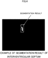
- the interventricular septum included in an ultrasonographic image sometimes seems to have a defect by noise. Noise can appear at a position different for each frame image of moving image data. Accordingly, in order to decide presence or absence of a defect in the interventricular septum included in the first frame image, it is important to perform segmentation for a portion of the interventricular septum using information of preceding and succeeding second frame images of the first frame image as exemplified in FIG. 4 .
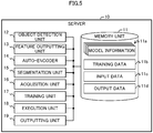
- FIG. 5 is a block diagram depicting an example of a functional configuration of a server 10 according to the embodiment.
- the server 10 is an apparatus that trains an NNW group for estimating a target from a frame image and estimates a target using the NNW group, and is an example of the information processing apparatus 1 depicted in FIG. 1 .
- the target of a segmentation target is an interventricular septum and the image for which segmentation is to be performed is an ultrasonographic image such as an echo image obtained by photographing the thoracic cage including the interventricular septum, for example, a fetus chest.
- the server 10 may illustratively include a memory unit 11, an object detection unit 12, a feature outputting unit 13, an auto-encoder 14, a segmentation unit 15, an acquisition unit 16, a training unit 17, an execution unit 18 and an outputting unit 19.
- the memory unit 11 is an example of a storage region and stores various information to be used for training the auto-encoder 14 and the segmentation unit 15, executing and outputting the estimation process using an NNW group and so forth. As depicted in FIG. 5 , the memory unit 11 may be illustratively capable of storing multiple pieces of model information 11a, training data 11b, input data 11c and output data 11d.
- the target detection unit 12 is an example of the target detection unit 2 depicted in FIG. 1 , and, for example, the target detection unit 12 detects a target from each of multiple inputted images and outputs multiple partial images including the detected target and a peripheral image of the target.
- a partial region is generated, for example, by cutting out a region including a target and a peripheral region of the target in a rectangular shape from the inputted image.
- the target detection unit 12 may be, for example, an object detection model generated using the training data 11b and trained in advance for specifying a region of the target included in an input image and may be an object detection NNW such as a YOLO as an example.
- a manager or a utilizer of the server 10 may execute training of the target detection unit 12 in advance using the training data 11b.
- the feature outputting unit 13 is an example of the feature outputting unit 3 depicted in FIG. 1 .
- the feature outputting unit 13 may be a trained model generated using a dataset of an image different from an image obtained by photographing a target and may be a trained model for estimating a label for an input image.
- a VGG-Backbone is available.
- the VGG-Backbone may be an NNW in which a fully connected layer as an outputting layer is removed from a VGG and which consequently includes a convolution layer and a pooling layer.
- a VGG is an example of a trained NNW usable in the embodiment.
- a trained NNW usable in the embodiment is not limited only to a VGG (or a VGG-Backbone).
- the feature outputting unit 13 since the feature outputting unit 13 is generated using a dataset of an image different from an image of the training data 11b, the feature outputting unit 13 may be a model obtained by diverting or processing a trained NNW such as a VGG publicly opened on the Internet or the like.
- the auto-encoder 14 is an example of the auto-encoder 4 depicted in FIG. 1 .
- the auto-encoder 14 for example, an NNW in which the number of units of an intermediate layer is smaller in comparison with those of the inputting layer and the outputting layer, as an example, an auto encoder, is available.
- the feature outputting unit 13 and the auto-encoder 14 collectively serve as an example of the support module 7.
- the segmentation unit 15 is an example of the segmentation unit 5 and an example of the segmentation module 8 depicted in FIG. 1 .
- various segmentation NNWs are available as the segmentation unit 15, in the embodiment, for example, it is assumed that a U-Net is used. It is to be noted that the segmentation unit 15 is not limited to the U-Net and may be a different neural network for executing Semantic Segmentation or may be a neural network using a segmentation method other than the Semantic Segmentation.
- Each of the auto-encoder 14 and the segmentation unit 15 is an NNW of a target a target to be trained in the training process in the server 10.
- the target detection unit 12, the feature outputting unit 13, the auto-encoder 14, and the segmentation unit 15 are sometimes referred to as "NNWs" or "NNW group”.
- Information of a network structure, various parameters and so forth for implementing the NNWs 12 to 15 may be stored as model information 11a for each of the NNWs 12 to 15 in the memory unit 11.
- the acquisition unit 16 acquires information to be used for training and execution of the auto-encoder 14 and the segmentation unit 15, for example, from a computer not depicted.
- the acquisition unit 16 may acquire and store the training data 11b to be used for training of the auto-encoder 14 and the segmentation unit 15 into the memory unit 11.
- the training data 11b may include moving image data obtained by photographing a target and multiple annotation images indicative of a region of the target in each of multiple frame images included in the moving image data.
- the training data 11b may include m (m: two or more, for example, higher than n, integer) image sets 110 as depicted in FIG. 6 .
- Each of the image sets 110 may include an image 111 obtained by photographing a target (that may be referred to as "training target") and an annotation image 112 as correct answer data of segmentation of the image 111.
- the image 111 is an example of a frame image and, for example, may be an echo image obtained by photographing the interventricular septum that is an example of a target as depicted in FIG. 6 .
- the image 111 may be referred to as "total image".
- the annotation image 112 is an example of an annotation image and is an image obtained by masking a target (in an example of FIG. 6 , "interventricular septum") in the image 111 of the image set 110, for example, as depicted in FIG. 6 .
- “mask” signifies, for example, that a region of a mask target is displayed in a mode distinguishable from a region that is not the mask target, and, as an example, "mask” may signify that a region of a mask target is filled with a predetermined color (a predetermined color is set to pixels in a region of a mask target).
- a masked region in other words, a region corresponding to the thorax, is indicated by painting in white while the other region, in other words, any region other than the thorax, is indicated by paining in black.
- the server 10 may perform training of the auto-encoder 14 and the segmentation unit 15 using multiple training data 11b, in other words, using a dataset for multiple f moving image data.
- the acquisition unit 16 may acquire and store input data 11c to be used in the estimation process by the NNW groups 12 to 15 into the memory unit 11.
- the input data 11c is an example of target data including target moving image data obtained by photographing an estimation target.
- the input data 11c may include multiple images 113 obtained by photographing a target (that may be referred to as "estimation target").
- the image 113 is an example of a target frame image and may be an echo image obtained by photographing the interventricular septum that is an example of the estimation target, for example, as depicted in FIG. 7 .
- the image 113 may be referred to as "total image".
- the training unit 17 is an example of a training execution unit and performs training of the auto-encoder 14 and the segmentation unit 15 using the training data 11b acquired by the acquisition unit 16.
- the execution unit 18 is an example of an estimation processing unit that executes an estimation process of a region of the estimation target for the input data 11c.
- the execution unit 18 performs the estimation process of segmentation of a target for the input data 11c using the trained auto-encoder 14 and the segmentation unit 15 that are trained by the training unit 17 and the input data 11c that is acquired by the acquisition unit 16.
- the outputting unit 19 may output (accumulate) a segmented image 115 that is to be described below and that is inputted from the execution unit 18 to (into) the memory unit 11, and generate output data 11d on the basis of multiple accumulated segmented images 115.
- the output data 11d includes an image set including one or more segmented images 115, in other words, one or more output images, and, for example, may be moving image data of a video including multiple frame images.
- the output data 11d may be a video obtained by coupling the segmented images 115 in a time series as frame images.
- the outputting unit 19 may transmit the output data 11d, for example, to a computer not depicted.
- FIG. 9 is a flow chart illustrating an example of operation of the training phase
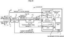
- FIG. 10 is a view illustrating an example of operation of the training phase.
- the NNW groups 12 to 15 may be coupled to each other by the configuration depicted in FIG. 10 in the server 10.
- the training unit 17 may include a combining unit 17a and an adding unit 17b hereinafter described as exemplified in FIG. 10 .
- the training unit 17 acquires (t-n)th to (t+n)th total images 111 and a (t)th annotation image 112 from time series images 111 included in training data 11b acquired by the acquisition unit 16 (step S1).
- the (t-n)th to (t+n)th total images 111 are referred to as “total images (t ⁇ n).” It is to be noted that the value of n may be, as an example, "3" or the like.
- the training unit 17 may generate total images 111 and an annotation image 112 by resizing the acquired (t-n)th to (t+n)th total images 111 and (t)th annotation image 112 into an input size to the target detection unit 12. Further, the training unit 17 may generate a total image 111 having a size resized to the input size to the feature outputting unit 13 from the size of the acquired (t)th total image 111.
- the training unit 17 inputs the resized (t-n)th to (t+n) total images 111 to the target detection unit 12 (step S2: refer to reference character A of FIG. 10 ).
- the training unit 17 inputs the resized (t)th total image 111 to the feature outputting unit 13 (step S3: refer to reference character B of FIG. 10 ).
- the feature outing unit 13 extracts a feature (feature amount) of the inputted (t)th total image 111 and inputs the extracted feature to an intermediate layer of the auto-encoder 14 (step S4: refer to reference character C of FIG. 10 ).
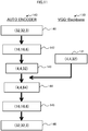
- FIG. 11 is a view depicting an example of a configuration of the feature outputting unit 13 and the auto-encoder 14.
- a VGG-Backbone (VGG backbone) 130 is an example of the feature outputting unit 13
- an Auto Encoder (auto encoder) 140 is an example of the auto-encoder 14.
- the VGG backbone 130 at least includes a layer 131 that outputs the feature extracted by the VGG backbone 130.
- the auto encoder 140 includes multiple layers 141 to 146 such as a convolution layer. It is to be noted that, in the example of FIG. 11 , one layer 131 of the VGG backbone 130 is depicted while illustration of layers in preceding stages to the layer 131 is omitted.
- (x, y, z) indicated in the blocks of the layer 131 and the layers 141 to 146 indicate a size of information to be utilized (processed) by the layers 131 to 141 to 146.
- the symbols "x" and “y” indicate sizes in the vertical and horizontal directions of an image
- the symbol "z” indicates a channel number.
- the feature outputted from the layer 131 of the VGG backbone 130 may be coupled (concatenated) in a channel direction to the output of the layer 143 of the auto encoder 140 and may be inputted to the layer 144 (refer to step S4 of FIG. 9 and reference character C of FIG. 10 ).
- the layer 144 performs a process using information of (4, 4, 64) in which the output (4, 4, 32) of the layer 143 and the output (4, 4, 32) of the layer 131 are coupled to each other in the channel (z) direction. Further, the layer 145 performs a process in which the feature that is the output (4, 4, 32) of the layer 131 is taken into account, and outputs information of (16, 16, 6) whose size is equal to that of the opposing layer 142.
- the layer 144 is an example of an intermediate layer of the auto-encoder 14.
- the intermediate layer may be, as an example, a layer whose size (x, y) is in the minimum, or in other words, may be a bottleneck of the auto encoder 140.
- the intermediate layer of the auto encoder 140 that serves as an outputting designation of a feature from the layer 131 is not limited to the example depicted in FIG. 11 but may be any of various layers between the input layer 141 and the output layer 146 among the layers of the auto encoder 140.
- the object detection unit 12 detects a target from each of the (t-n)th to (t+n)th total images 111 inputted in step S2 (reference character A in FIG. 10 ), and outputs target peripheral images 12a to 12c including the detected target and a peripheral region of the detected target.
- the training unit 17 inputs the (t)th target peripheral image 12c outputted from the object detection unit 12 to the segmentation unit 15 (step S5: refer to reference character D in FIG. 10 ).
- the segmentation unit 15 inputs a segmentation image 15a obtained by segmentation (for example, masking) of the target on the basis of the (t)th target peripheral image 12c to the adding unit 17b (step S6: refer to reference character E in FIG. 10 ).
- the training unit 17 combines, by the combining unit 17a thereof, n (t-n)th to (t-1)th target peripheral images 12a and n (t+1)th to (t+n)th target peripheral images 12b outputted from the object detection unit 12 (refer to FIG. 10 ).
- the combining unit 17a may line up, for example, n images in a channel direction to output a combined image 12e.
- the combining unit 17a may output two combined images 12e including a combined image 12e in which the n (t-n)th to (t-1)th target peripheral images 12a are used and another combined image 12e in which the n (t+1)th to (t+n)th target peripheral images 12b are used.
- the combining unit 17a may otherwise output one combined image 12e, using the (t-n)th to (t-1)th and (t+1)th to (t+n)th target peripheral images 12a and 12b (2n images).
- the training unit 17 inputs the combined image 12e outputted from the combining unit 17a to the auto-encoder 14 (step S7: refer to reference character F in FIG. 10 ).
- the auto-encoder 14 receives the combined images 12e of the (t-n)th to (t-1)th and (t+1)th to (t+n)th images as an input to the input layer and receives a feature inputted from the feature outputting unit 13 as an input to the intermediate layer thereof, and outputs an output image 14a from the output layer.
- the input layer may be the layer 141; the intermediate layer may be the layer 144; and the output layer may be the layer 146.
- the training unit 17 inputs the output image 14a outputted from the auto-encoder 14 to the adding unit 17b (step S8: refer to reference character G in FIG. 10 ).
- FIG. 12 is a view illustrating an example of a configuration and operation of the adding unit 17b.
- the adding unit 17b may illustratively include processing functions of an addition processing unit 171, a difference calculation unit 172 and a training processing unit 173.
- the addition processing unit 171 adds a segmentation image 15a outputted from the segmentation unit 15 and an output image 14a outputted from the auto-encoder 14 for each cell to generate a combined output-image 12f (step S9: refer to reference character H in FIG. 12 ).
- the difference calculation unit 172 calculates a difference 12g between the combined output-image 12f outputted from the addition processing unit 171 and a target peripheral annotation image 12d outputted from the object detection unit 12 and outputs the difference 12g to the training processing unit 173.
- various known methods such as, for example, a least squares method can be applied.
- the training unit 17 inputs a resized (t)th annotation image 112 to the object detection unit 12 (step S10: refer to reference character I in FIG. 10 ).
- step S10 the inputting of the annotation image 112 to the object detection unit 12 (step S10) may be performed, for example, in parallel to the inputting of the (t-n)th to (t+n)th total images 111 to the object detection unit 12 and the feature outputting unit 13 (steps S2 and S3).
- the object detection unit 12 outputs a target peripheral annotation image 12d obtained by cutting out, from the inputted (t)th annotation image 112, a partial region same as that of the (t)th target peripheral image 12c.
- the training unit 17 inputs the (t)th target peripheral annotation image 12d outputted from the object detection unit 12 to the difference calculation unit 172 of the adding unit 17b (step S11: refer to reference character J in FIG. 10 and reference character K in FIG. 12 ).
- the training processing unit 173 performs training of the auto-encoder 14 and the segmentation unit 15 on the basis of the difference 12g calculated by the difference calculation unit 172 (step S12: refer to reference character L in FIG. 12 ), and the processing ends therewith.
- various machine learning methods may be used.
- a back propagation process of determining (updating) a parameter to be used in processes in a forward propagation direction by the auto-encoder 14 and the segmentation unit 15 may be executed.
- an update process of updating a variable such as a weight may be executed on the basis of a result of the back propagation process.
- the training unit 17 may repeatedly execute the machine learning process of the auto-encoder 14 and the segmentation unit 15, for example, using multiple image sets 110 included in training data 11b until a number of iterations, accuracy, or the like reaches a threshold value.
- the auto-encoder 14 and the segmentation unit 15 for which the training is completed are examples of a trained model.
- the training unit 17 may execute the processes in steps S1 to S12 depicted in FIG. 9 using each of the multiple total images 111 in the training data 11b as a first frame image by changing the value of (t) corresponding to the frame number in the moving image data. It is to be noted that the total images 111 up to the (n-1)th total image 111 from the top and the end in the moving image data as the training data 11b may be excluded from a selection target for a first frame image.
- FIG. 13 is a flow chart illustrating an example of operation of the estimation phase
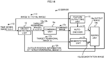
- FIGS. 14 and 15 are views illustrating an example of operation of the estimation phase.
- the execution unit 18 may include a combination unit 18a and an adding unit 18b to be described below as exemplified in FIG. 14 in order to perform estimation of segmentation of an estimation target in the estimation phase.
- the combination unit 18a may have a processing function similar to that of the combining unit 17a.
- FIG. 14 is basically similar to FIG. 9 in terms of flows of data although it is different from FIG. 9 in reference character of the image 113, in that the annotation image 112 is not inputted to the object detection unit 12, in that the object detection unit 12 outputs cutout position information 12h of the target peripheral image 12c in place of the target peripheral annotation image 12d, and in the configuration of the adding unit 18b.
- the execution unit 18 acquires the (t-n)th to (t+n)th total images 113 from among the time series images 113 included in the input data 11c acquired by the acquisition unit 16 (step S21: refer to FIG. 14 ).
- the (t)th total image 113 is an example of a third frame image
- the (t-n)th to (t-1)th and (t+1)th to (t+n)th total images 113 are an example of a predetermined number of preceding and succeeding fourth frame images of the third frame image in the time series of target moving image data.
- the execution unit 18 may generate total images 113', for example, by resizing the sizes of the acquired (t-n)th to (t+n)th total images 113 to the input size of the object detection unit 12. Further, the execution unit 18 may generate a total image 113" by resizing the size of the acquired (t)th image 113 to the input size of the feature outputting unit 13.
- the execution unit 18 inputs the resized (t-n)th to (t+n)th total images 113' to the object detection unit 12 (step S22).
- the execution unit 18 inputs the resized (t)th total image 113" to the feature outputting unit 13 (step S23).
- the feature outputting unit 13 extracts a feature of the inputted (t)th total image 113" and inputs the extracted feature to the intermediate layer of the auto-encoder 14 (step S24).
- the object detection unit 12 detects the estimation target from each of the (t-n)th to (t+n)th total images 113' inputted in step S22. Then, the object detection unit 12 outputs the target peripheral images 12a to 12c (refer to FIG. 15 ) including the detected estimation target and a peripheral region of the estimation target, in other words, multiple partial images.
- the execution unit 18 inputs the (t)th target peripheral image 12c outputted from the object detection unit 12 to the segmentation unit 15 trained with parameter update by the training unit 17 (step S25).
- the segmentation unit 15 inputs a segmentation image 15a (refer to FIG. 15 ) obtained by segmenting the estimation target on the basis of the inputted target peripheral image 12c to the adding unit 18b (step S26).
- the execution unit 18 combines, by the combination unit 18a thereof, the n (t-n)th to (t-1)th target peripheral images 12a and the n (t+1)th to (t+n)th target peripheral images 12b outputted from the object detection unit 12.
- the combination unit 18a may output a combined image 12e, for example, by lining up n images in the channel direction similarly to the combining unit 17a. It is to be noted that the combination unit 18a may output one combined image 12e using the (t-n)th to (t-1)th and (t+1)th to (t+n)th target peripheral images 12a and 12b (2n images).
- the execution unit 18 inputs the combined image 12e outputted from the combination unit 18a to the auto-encoder 14 trained already with parameter update by the training unit 17 (step S27).
- the auto-encoder 14 receives the (t-n)th to (t-1)th and (t+1)th to (t+n)th combined images 12e as an input to the input layer thereof and receives the feature inputted from the feature outputting unit 13 as an input to the intermediate layer thereof, and outputs an output image 14a (refer to FIG. 15 ) from the output layer thereof.
- the execution unit 18 inputs the output image 14a outputted from the auto-encoder 14 to the adding unit 18b (step S28).
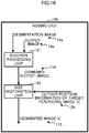
- FIG. 16 is a view illustrating an example of a configuration and operation of the adding unit 18b.
- the adding unit 18b may illustratively include processing functions of an addition processing unit 181 and a size restoration unit 182.
- the addition processing unit 181 adds the segmentation image 15a outputted from the segmentation unit 15 and the output image 14a outputted from the auto-encoder 14 for each pixel to generate a combined output-image 114 (refer to FIG. 15 ) (step S29).
- the size restoration unit 182 receives as inputs thereto the combined output-image 114 outputted from the addition processing unit 181 and the cutout position information 12h of the target peripheral image 12c outputted from the object detection unit 12.
- cutout position information 12h inputted to the size restoration unit 182 is described.
- the object detection unit 12 when the (t)th total image 113' is inputted in step S22, the object detection unit 12 outputs the cutout position information 12h of the target peripheral image 12c in the total image 113' together with the target peripheral image 12c.
- the execution unit 18 inputs, for example, the cutout position information 12h outputted from the object detection unit 12 to the size restoration unit 182 of the adding unit 18b (step S30: refer to FIGS. 15 and 16 ).
- the cutout position information 12h is an example of position information indicative of the position in the (t)th total image 113' from which the (t)th target peripheral image 12c is cut out.
- the cutout position information 12h for example, coordinate information indicative of a cutout position (region) of the target peripheral image 12c in the total image 113' or like information is available.
- the size restoration unit 182 returns, on the basis of the combined output-image 114 and the cutout position information 12h, the size of the combined output-image 114 to the original size of the total image 113 to generate a segmented image 115 (step S31).
- the segmented image 115 is an example of an image that includes a region estimated as an estimation target in the total image 113.
- the size restoration unit 182 may fit the combined output-image 114 into the original (t)th image 113 on the basis of the cutout coordinates indicated by the cutout position information 12h to perform restoration.
- the (t)th total image 113 may be inputted in addition to the cutout position information 12h of the (t)th target peripheral image 12c.
- the execution unit 18 may change, for example, the value of (t) corresponding to the frame number in the target moving image data to set each of the multiple total images 113 in the input data 11c as a third frame image to execute the processes in steps S21 to S31 depicted in FIG. 13 . It is to be noted that the images 113 up to the (n-1)th image 113 from the top and the end in the moving image data as the input data 11c may be excluded from a selection target for a third frame image.
- the outputting unit 19 accumulates the segmented images 115 and outputs output data 11d in which the accumulated segmented images 115 are combined to the output data 11d (step S32), and the processing ends therewith. It is to be noted that, as the outputting destination of the output data 11d, for example, a computer or the like not depicted is available in addition to the memory unit 11.
- the execution unit 18 and the outputting unit 19 are an example of an image outputting unit that outputs an image including a region estimated as an estimation target in a third frame image on the basis of the combined output-image 114 and the cutout position information 12h.
- segmentation of a target is performed by inputting the following three kinds of images 113 and 12a to 12c to the NNWs 13 to 15 different from one another and integrating outputs (results) from the NNWs 13 to 15.
- the server 10 inputs an image 12c, in which a peripheral region of a target in a frame image of the target is enlarged, to the segmentation unit 15. Further, the server 10 inputs images 12a and 12b in which a target peripheral region is enlarged in frame images preceding to and succeeding the frame image of the target to the auto-encoder 14. Furthermore, the server 10 inputs the image 113 of the entire frame of the target to the feature outputting unit 13.
- the auto-encoder 14 can output, based on the frame images preceding to and succeeding the frame image of the target, an output image 14a, from which an influence of noise of the object included in the frame image of the target has been decreased.
- the auto-encoder 14 can utilize information of portions other than the cutout portion.
- the auto-encoder 14 can output the output image 14a that takes the direction of the target into consideration.
- the output image 14a from the auto-encoder 14 and the segmentation image 15a from the segmentation unit 15 are outputted. Consequently, for example, a user of the server 10 can compare, in the estimation phase, the output image 14a and the segmentation image 15a with each other to decide in what point the output image 14a has been amended with respect to the segmentation image 15a solely from the segmentation unit 15.
- FIG. 17 is a block diagram depicting an example of a hardware (HW) configuration of a computer 20 that implements the functions of the information processing apparatus 1 and the server 10.
- HW hardware
- the computer 20 may illustratively include a processor 20a, a memory 20b, a storage unit 20c, an interface (IF) unit 20d, an input/output (I/O) unit 20e and a reading unit 20f as a hardware configuration.
- the processor 20a is an example of an arithmetic processing unit that performs various controls and arithmetic operations.
- the processor 20a may be coupled for mutual communication to the blocks in the computer 20 by a bus 20i.
- the processor 20a may be a multiprocessor including multiple processors or may be a multicore processor having multiple processor cores or otherwise may be configured so as to have multiple multicore processors.
- processor 20a integrated circuits such as, for example, a CPU, an MPU, a GPU, an APU, a DSP, an ASIC and an FPGA are available. It is to be noted that, as the processor 20a, a combination of two or more of such integrated circuits as mentioned above may be used.
- processing functions of at least part of the information processing apparatus 1, the acquisition unit 16 of the server 10, at least part of the training unit 17, at least part of the execution unit 18 and the outputting unit 19 may be implemented by a CPU, an MPU or the like as the processor 20a.
- processing functions of at least part of the information processing apparatus 1, the NNWs 12 to 15 of the server 10, at least part of the training unit 17 and at least part of the execution unit 18 may be implemented by an accelerator such as a GPU or an ASIC (for example, a TPC) within the processor 20a.
- CPU is an abbreviation of Central Processing Unit
- MPU is an abbreviation of Micro Processing Unit
- GPU is an abbreviation of Graphics Processing Unit
- APU is an abbreviation of Accelerated Processing Unit
- DSP is an abbreviation of Digital Signal Processor
- ASIC is an abbreviation of Application Specific IC
- FPGA is an abbreviation of Field-Programmable Gate Array.
- TPU is an abbreviation of Tensor Processing Unit.
- the memory 20b is an example of HW that stores information of various data, programs and so forth.
- a volatile memory such as a dynamic random access memory (DRAM)
- a nonvolatile memory such as a persistent memory (PM) are available.
- the storage unit 20c is an en example of HW that stores information of various data, programs and so forth.
- various storage devices such as a magnetic disk device such as a hard disk drive (HDD), a semiconductor drive device such as a solid state drive (SSD) and a nonvolatile memory are available.
- a nonvolatile memory for example, a flash memory, a storage class memory (SCM), a read only memory (ROM) and so forth are available.
- the storage unit 20c may store a program 20g (training program) that implements all or part of various functions of the computer 20.
- the processor 20a of the information processing apparatus 1 can implement functions as the information processing apparatus 1 exemplified in FIGS. 1 and 2 by expanding the program 20g stored in the storage unit 20c on the memory 20b and executing the expanded program 20g.
- the processor 20a of the server 10 can implement the functions as the server 10 exemplified in FIGS. 5 , 10 , 12 , 14 and 16 by expanding the program 20g stored in the storage unit 20c on the memory 20b and executing the expanded program 20g.
- the storage region at least one of the memory 20b and the storage unit 20c has may be capable of storing the information 11a to 11d depicted in FIG. 5 .
- the memory unit 11 of FIG. 5 may be implemented by a storage region at least one of the memory 20b and the storage unit 20c has.
- the IF unit 20d is an example of a communication IF that performs control and so forth of coupling to and communication with a network.
- the IF unit 20d may include an adapter that complies with a local area network (LAN) such as the Ethernet (registered trademark) or optical communication such as the Fibre Channel (FC) or the like.
- the adapter may be compatible with a communication method for one of or both wireless and wired communication.
- the server 10 may be coupled for mutual communication to a different apparatus through the IF unit 20d.
- the program 20g may be downloaded from the network to the computer 20 through the communication IF and stored into the storage unit 20c.
- the I/O unit 20e may include one of or both an inputting apparatus and an outputting apparatus.
- an inputting apparatus for example, a keyboard, a mouse, a touch panel and so forth are available.
- an outputting apparatus for example, a monitor, a projector, a printer and so forth are available.
- the reading unit 20f is an example of a reader for reading out information of data and programs recorded on a recording medium 20h.
- the reading unit 20f may include a connection terminal or device to or into which the recording medium 20h can be connected or inserted.
- an adapter that complies with Universal Serial Bus (USB) or the like, a drive device that accesses a recording disk, a card reader that accesses a flash memory such as an SD card and so forth are available.
- USB Universal Serial Bus
- the recording medium 20h has the program 20g stored therein and the reading unit 20f may read out the program 20g from the recording medium 20h and store the program 20g into the storage unit 20c.
- the recording medium 20h illustratively a non-transitory computer-readable recording medium such as a magnetic/optical disk, a flash memory and so forth are available.
- a magnetic/optical disk illustratively a flexible disk, a compact disc (CD), a digital versatile disc (DVD), a Blu-ray (registered trademark) disk, a holographic versatile disc (HVD) and so forth are available.
- the flash memory illustratively a semiconductor memory such as a USB memory or an SD card is available.
- the HW configuration of the computer 20 described above is exemplary. Accordingly, increase or decrease of HW in the computer 20 (for example, addition or deletion of an arbitrary block), division, integration in arbitrary combination, addition or deletion of a bus and so forth may be performed suitably.
- increase or decrease of HW in the computer 20 for example, addition or deletion of an arbitrary block
- division, integration in arbitrary combination, addition or deletion of a bus and so forth may be performed suitably.
- at least one of the I/O unit 20e and the reading unit 20f may be omitted.
- processing functions 12 to 19 provided in the server 10 depicted in FIG. 5 may individually be merged or divided in arbitrary combinations.
- the target and the image are an interventricular septum and an echo image, respectively, they are not restrictive.
- the technique according to the embodiment can be applied also to various objects and images as described below.
- the target for example, in addition to a part of the human body, various objects in regard to which one or both of the size and the amount of movement of the target is comparatively small with respect to the total region of an image are available. Further, the target does not have to be an object that can be viewed with the naked eye, for example, like an object at least part of which is buried in the ground.
- the image various images obtained by photographing a region including a target are available. For example, as the image, various images are available including an ultrasonic image other than an echo image, a magnetic resonance image, an X-ray image, a detection image by a sensor that captures a temperature, electromagnetic waves or the like, and a captured image by an image sensor that captures visible light or invisible light.
- the server 10 depicted in FIG. 5 may be configured such that the various processing functions are implemented by multiple apparatus that cooperate with each other through a network.
- the acquisition unit 16 and the outputting unit 19 may be a Web server; the NNWs 12 to 15, training unit 17 and execution unit 18 may be an application server; and the memory unit 11 may be a database (DB) server.
- the Web server, application server and DB server may cooperate with each other through a network to implement the processing functions as the server 10.
- processing functions relating to the training process of the NNWs 14 and 15 acquisition unit 16 and training unit 17
- estimation process execution unit 18 and outputting unit 19
- the devices may cooperate with each other through a network to implement the processing functions as the server 10.
Landscapes
- Engineering & Computer Science (AREA)
- Theoretical Computer Science (AREA)
- Physics & Mathematics (AREA)
- General Physics & Mathematics (AREA)
- Data Mining & Analysis (AREA)
- General Health & Medical Sciences (AREA)
- Health & Medical Sciences (AREA)
- Life Sciences & Earth Sciences (AREA)
- Evolutionary Computation (AREA)
- General Engineering & Computer Science (AREA)
- Artificial Intelligence (AREA)
- Molecular Biology (AREA)
- Software Systems (AREA)
- Mathematical Physics (AREA)
- Computing Systems (AREA)
- Biomedical Technology (AREA)
- Biophysics (AREA)
- Computational Linguistics (AREA)
- Computer Vision & Pattern Recognition (AREA)
- Multimedia (AREA)
- Medical Informatics (AREA)
- Nuclear Medicine, Radiotherapy & Molecular Imaging (AREA)
- Radiology & Medical Imaging (AREA)
- Quality & Reliability (AREA)
- Evolutionary Biology (AREA)
- Bioinformatics & Computational Biology (AREA)
- Bioinformatics & Cheminformatics (AREA)
- Image Analysis (AREA)
Abstract
Description
- The present invention relates to a training program, a training method, and an information processing apparatus.
- A technology is available which performs, in order to detect a target from moving image data obtained by photographing a target, segmentation using a neural network (NNW) for each of frame images included in the moving image data.
- As a first method, a technology is available in which a combined image (for example, an optical flow) representative of a motion of a target is inputted to one of two NNWs like a 2-way network and segmentation of the target is performed using a segmentation network for a still picture of the other one of the two NNWs.
- As a second method, a technology is available in which several preceding and succeeding frame images of moving image data are inputted together to an NNW to perform segmentation of a target.
- [Non-Patent Document 1] Joseph Redmon, Santosh Divvala, Ross Girshick, Ali Farhadi, "You Only Look Once: Unified, Real-Time Object Detection", arXiv: 1506.02640v5 [cs.CV], laid-open date: May 9, 2016
- For example, a case is assumed in which moving image data is such moving image data that it includes much noise and indicates a small movement of a target like moving image data of an ultrasonography video or a surveillance video photographed by a surveillance camera and having comparatively-low picture quality. In the case where a target is detected from such moving image data as just described including a shape of the target, the first and second methods described above sometimes suffer from such inconveniences as described below.
- The first method is suitable for segmentation of a target with movement like a running vehicle, in other words, a target whose position changes between image frames, because a combined image (for example, an optical flow) representative of a movement of the target is used as one of inputs. However, the first method is not suitable for detailed segmentation specified for a target region such as moving image data obtained by photographing a target whose change in position is comparatively small.
- In the second method, it is difficult to perform training taking a frame image of a target for which segmentation is to be performed into consideration. Therefore, for example, even if a target does not appear in a target frame image, if the target appears in preceding or succeeding frame images of the target frame image, then there is the possibility that the NNW detects the target in the target frame image in error.
- In this manner, it is considered that both of the first and second methods described above are low in robustness against noise of a frame image of moving image data in object detection of the frame image.
- According to one aspect, it is an object of the present technology to improve the robustness against noise of a frame image of moving image data in object detection of the frame image.
- According to an aspect of the embodiments, a training program that causes a computer to execute a process includes: acquiring training data including moving image data obtained by photographing a target and a plurality of annotation images each indicative of a region of the target in each of a plurality of frame images included in the moving image data; and executing a training process using the training data. The training process includes: detecting the target included in the plurality of frame images; inputting a combined image to an auto-encoder, the combined image being obtained by combining a plurality of partial images including the target and a plurality of peripheral region images of the target, the plurality of partial images and plurality of peripheral region images being detected in a given number of preceding and succeeding second frame images in a time series of the moving image data of a first frame image from among the plurality of frame images; inputting a partial image, in the plurality of partial images, corresponding to the first frame image to a neural network that performs a segmentation process for an image; and performing parameter update of the auto-encoder and the neural network, based on a difference between a combination output image obtained by combining an output image from the auto-encoder and an output image from the neural network and a partial image of the annotation image indicative of a region of the target in the first frame image.
- According to the one aspect, the robustness of a frame image of moving image data against noise in object detection of the frame image can be improved.
-
-
FIG. 1 is a view illustrating an example of a training process by an information processing apparatus according to an embodiment; -
FIG. 2 is a view illustrating a different example of the training process by the information processing apparatus according to the embodiment; -
FIG. 3 is a view depicting an example of a sectional view of a thorax of an ultrasonographic image; -
FIG. 4 is a view depicting an example of a segmentation result of a thoracic region; -
FIG. 5 is a block diagram depicting an example of a functional configuration of a server according to the embodiment; -
FIG. 6 is a view depicting an example of training data; -
FIG. 7 is a view depicting an example of input data; -
FIG. 8 is a view depicting an example of output data; -
FIG. 9 is a flow chart illustrating an example of operation of a training phase; -
FIG. 10 is a view illustrating an example of operation of the training phase; -
FIG. 11 is a view depicting an example of a configuration of a feature outputting unit and an auto-encoder; -
FIG. 12 is a view illustrating an example of a configuration and operation of an adding unit; -
FIG. 13 is a flow chart illustrating an example of operation of an estimation phase; -
FIG. 14 is a view illustrating an example of operation of the estimation phase; -
FIG. 15 is a view illustrating an example of operation of the estimation phase; -
FIG. 16 is a view illustrating an example of a configuration and operation of the adding unit; and -
FIG. 17 is a block diagram depicting an example of a hardware configuration of a computer according to the embodiment. - In the following, an embodiment of the present technology is described with reference to the drawings. However, the embodiment described below is illustrative to the end, and there is no intention to eliminate various modifications and applications of the technology that are not specified in the following. For example, the present embodiment can be carried out in various modified forms without departing from the subject matter of the present technology. It is to be noted that, unless otherwise specified, in the drawings referred to in the following description of the embodiment, same or like elements are denoted by like reference characters.
-
FIG. 1 is a view illustrating an example of a training process by aninformation processing apparatus 1 according to the embodiment. It is to be noted that, in the description with reference toFIG. 1 , "moving image data" signifies video data such as an echo image obtained by photographing a comparatively small target with respect to a size of a frame image and including noise, and "target" signifies a predetermined part of a photographing target of an echo image. - The
information processing apparatus 1 acquires training data including moving image data obtained by photographing a target and multiple annotation images indicative of a region of the target in each of multiple frame images included in the moving image data. Then, theinformation processing apparatus 1 executes a training process using the training data. - For example, as depicted in
FIG. 1 , theinformation processing apparatus 1 executes processes of (a) to (d) described below for each of multiple frame images in the training process. As an example, the processes of (a) to (d) may be repeatedly executed, changing while a first frame image that is a target (noticed) frame image in a time series order of the moving image data. In the following description, an entire frame image is sometimes referred to as "total image". - For example, as depicted in
FIG. 1 , theinformation processing apparatus 1 may detect a target included in (t-n)th to (t+n)thtotal images 1a in a time series of moving image data from among multiple frame images. The symbol "t" is a variable indicative of the first frame image. n indicates an integer equal to or greater than one and is an example of a given number (predetermined number). Further, (t-n)th to (t-1)th and (t+1)th to (t+n)th frame images are an example of n preceding and n succeedingsecond frame images 1a of thefirst frame image 1a. It is to be noted that, inFIG. 1 and the following drawings, the (t-n)th to (t+n)th total images are denoted by "total images (t±n)" for simplified illustration. - It is to be noted that the
information processing apparatus 1 may detect the target included in anannotation image 1b of the (t)thtotal image 1a included in the training data in addition to the foregoing. - The
information processing apparatus 1 may detect the target from thetotal image 1a and theannotation image 1b, for example, by anobject detection unit 2. Theobject detection unit 2 may be a trained object detection model generated, for example, using a dataset of the training data for specifying a region of the target included in an input image, and may be an object detection NNW such as a YOLO as an example. - The
object detection unit 2 may output targetperipheral images 2a to 2c and a targetperipheral annotation image 2d as a result of the detection of the target. - The target
peripheral image 2a is multiple partial images including a target and a peripheral region of the target detected in n frame images preceding to thefirst frame image 1a, namely, in the (t-n)th to (t-1)thsecond frame images 1a. - The target
peripheral image 2b is multiple partial images including a target and a peripheral region of the target detected in n frame images succeeding thefirst frame image 1a, namely, in the (t+1)th to (t+n)thsecond frame images 1a. - It is to be noted that, in
FIG. 1 and the succeeding figures, for simplified illustration, the (t-n)th to (t-1)th targetperipheral images 2a and (t+1)th to (t+n)th targetperipheral images 2b are denoted by "target peripheral images (t-n)" and "target peripheral images (t+n)", respectively. - The target
peripheral image 2c is a partial image including a target and a peripheral region of the target that are detected in the (t)thfirst frame image 1a. - The target
peripheral annotation image 2d is a partial image including a target and a peripheral region of the target that are detected in theannotation image 1b, and is, for example, a partial image obtained by cutting out a partial region the same as that of the targetperipheral image 2c from theannotation image 1b. - For example, the
information processing apparatus 1 may combine n targetperipheral images - The auto-encoder 4 is an example of a
support module 7. For example, as the auto-encoder 4 is exemplified by an NNW in which the number of units in an intermediate layer is small in comparison with the number of units of each of an input layer and an output layer, such as an auto encoder. - The segmentation unit 5 is an example of a segmentation module 8. Although, as the segmentation unit 5, various NNWs for segmentation are available, in the embodiment, for example, the U-Net is used. It is to be noted that the segmentation unit 5 is not limited to the U-Net, and may be a different neural network that executes Semantic Segmentation or maybe a neural network that uses a segmentation method other than the Semantic Segmentation.
- Each of the auto-encoder 4 and the segmentation unit 5 is an NNW that is a target to be trained in a training process.
- The
information processing apparatus 1 may generate the combined output-image by adding the output image from the auto-encoder 4 and the output image from the segmentation unit 5 for each pixel, for example, by an adding unit 6. The combined output-image is an example of a segmented image. Then, theinformation processing apparatus 1 may input the targetperipheral annotation image 2d, for example, to the adding unit 6 and may train the auto-encoder 4 and the segmentation unit 5 by backward error propagation or the like on the basis of the difference between the combined output-image and the targetperipheral annotation image 2d. - Consequently, the
information processing apparatus 1 can train asupport module 7 that outputs complementation information based on a context of preceding and succeeding images of thefirst frame image 1a on the basis of the targetperipheral annotation image 2d. Further, theinformation processing apparatus 1 can train the segmentation module 8 on the basis of the targetperipheral annotation image 2d. - Accordingly, in object detection of the
frame image 1a of the moving image data, even if noise is included in theframe image 1a, a network for outputting a segmentation result focusing on thefirst frame image 1a can be constructed, considering the preceding and succeeding images of thefirst frame image 1a. - From the foregoing, with the
information processing apparatus 1, robustness against noise of theframe image 1a in object detection of theframe image 1a of the moving image data can be improved. - Further, the
information processing apparatus 1 according to the embodiment includes afeature outputting unit 3 in thesupport module 7 as exemplified inFIG. 2 . Thefeature outputting unit 3 may be a trained model generated using a dataset of an image different from theframe image 1a obtained by photographing a target and may be a trained model for estimating a label to an input image. - As the
feature outputting unit 3, for example, VGG-Backbone is available. The VGG-Backbone may be, for example, an NNW equivalent to a trained NNW such as a VGG from which an output layer is removed. As an example, the VGG-Backbone may be an NNW including a convolution layer and a pooling layer with a fully connected layer as an outputting later removed from a VGG. It is to be noted that the VGG is an example of a trained NNW usable in the embodiment. The trained NNW to be utilized in the embodiment is not limited only to the VGG (or the VGG-Backbone). - For example, the
information processing apparatus 1 depicted inFIG. 2 may input a feature relating to the entirefirst frame image 1a obtained by inputting the (t)th first frame image (total image) 1a to thefeature outputting unit 3, in other words, a context relating to the entire image, to an intermediate layer of the auto-encoder 4. - It is to be noted that the intermediate layer of the auto-encoder 4 may be a bottleneck of the auto-encoder 4 and may be, as an example, a layer in which the size (vertical and horizontal sizes) of an image to be processed is in the minimum from among layers of the auto-encoder 4.
- Consequently, the auto-encoder 4 to which a combined image of the target
peripheral images feature outputting unit 3 in addition to the context of preceding and succeeding images of thefirst frame image 1a. Accordingly, the accuracy of the output from the auto-encoder 4 can be enhanced. - In the following description, a case in which the training process and the estimation process by the
information processing apparatus 1 are utilized for decision of presence or absence of defect in a site called interventricular septum of the heart in ultrasonographic image diagnosis is described as an example. - As exemplified in
FIG. 3 , the interventricular septum included in an ultrasonographic image sometimes seems to have a defect by noise. Noise can appear at a position different for each frame image of moving image data. Accordingly, in order to decide presence or absence of a defect in the interventricular septum included in the first frame image, it is important to perform segmentation for a portion of the interventricular septum using information of preceding and succeeding second frame images of the first frame image as exemplified inFIG. 4 . -
FIG. 5 is a block diagram depicting an example of a functional configuration of aserver 10 according to the embodiment. Theserver 10 is an apparatus that trains an NNW group for estimating a target from a frame image and estimates a target using the NNW group, and is an example of theinformation processing apparatus 1 depicted inFIG. 1 . - In the description of the embodiment, it is assumed that the target of a segmentation target is an interventricular septum and the image for which segmentation is to be performed is an ultrasonographic image such as an echo image obtained by photographing the thoracic cage including the interventricular septum, for example, a fetus chest.
- As depicted in
FIG. 5 , theserver 10 may illustratively include amemory unit 11, anobject detection unit 12, afeature outputting unit 13, an auto-encoder 14, asegmentation unit 15, anacquisition unit 16, atraining unit 17, anexecution unit 18 and anoutputting unit 19. - The
memory unit 11 is an example of a storage region and stores various information to be used for training the auto-encoder 14 and thesegmentation unit 15, executing and outputting the estimation process using an NNW group and so forth. As depicted inFIG. 5 , thememory unit 11 may be illustratively capable of storing multiple pieces ofmodel information 11a, training data 11b,input data 11c andoutput data 11d. - The
target detection unit 12 is an example of thetarget detection unit 2 depicted inFIG. 1 , and, for example, thetarget detection unit 12 detects a target from each of multiple inputted images and outputs multiple partial images including the detected target and a peripheral image of the target. A partial region is generated, for example, by cutting out a region including a target and a peripheral region of the target in a rectangular shape from the inputted image. - The
target detection unit 12 may be, for example, an object detection model generated using the training data 11b and trained in advance for specifying a region of the target included in an input image and may be an object detection NNW such as a YOLO as an example. For example, a manager or a utilizer of theserver 10 may execute training of thetarget detection unit 12 in advance using the training data 11b. - The
feature outputting unit 13 is an example of thefeature outputting unit 3 depicted inFIG. 1 . For example, thefeature outputting unit 13 may be a trained model generated using a dataset of an image different from an image obtained by photographing a target and may be a trained model for estimating a label for an input image. - As the
feature outputting unit 13, for example, a VGG-Backbone is available. As an example, the VGG-Backbone may be an NNW in which a fully connected layer as an outputting layer is removed from a VGG and which consequently includes a convolution layer and a pooling layer. It is to be noted that a VGG is an example of a trained NNW usable in the embodiment. A trained NNW usable in the embodiment is not limited only to a VGG (or a VGG-Backbone). - It is to be noted that, since the
feature outputting unit 13 is generated using a dataset of an image different from an image of the training data 11b, thefeature outputting unit 13 may be a model obtained by diverting or processing a trained NNW such as a VGG publicly opened on the Internet or the like. - The auto-
encoder 14 is an example of the auto-encoder 4 depicted inFIG. 1 . As the auto-encoder 14, for example, an NNW in which the number of units of an intermediate layer is smaller in comparison with those of the inputting layer and the outputting layer, as an example, an auto encoder, is available. - The
feature outputting unit 13 and the auto-encoder 14 collectively serve as an example of thesupport module 7. - The
segmentation unit 15 is an example of the segmentation unit 5 and an example of the segmentation module 8 depicted inFIG. 1 . Although various segmentation NNWs are available as thesegmentation unit 15, in the embodiment, for example, it is assumed that a U-Net is used. It is to be noted that thesegmentation unit 15 is not limited to the U-Net and may be a different neural network for executing Semantic Segmentation or may be a neural network using a segmentation method other than the Semantic Segmentation. - Each of the auto-
encoder 14 and thesegmentation unit 15 is an NNW of a target a target to be trained in the training process in theserver 10. - In the following description, the
target detection unit 12, thefeature outputting unit 13, the auto-encoder 14, and thesegmentation unit 15 are sometimes referred to as "NNWs" or "NNW group". - Information of a network structure, various parameters and so forth for implementing the
NNWs 12 to 15 may be stored asmodel information 11a for each of theNNWs 12 to 15 in thememory unit 11. - The
acquisition unit 16 acquires information to be used for training and execution of the auto-encoder 14 and thesegmentation unit 15, for example, from a computer not depicted. - For example, the
acquisition unit 16 may acquire and store the training data 11b to be used for training of the auto-encoder 14 and thesegmentation unit 15 into thememory unit 11. - The training data 11b may include moving image data obtained by photographing a target and multiple annotation images indicative of a region of the target in each of multiple frame images included in the moving image data.
- For example, the training data 11b may include m (m: two or more, for example, higher than n, integer) image sets 110 as depicted in
FIG. 6 . Each of the image sets 110 may include animage 111 obtained by photographing a target (that may be referred to as "training target") and anannotation image 112 as correct answer data of segmentation of theimage 111. - The
image 111 is an example of a frame image and, for example, may be an echo image obtained by photographing the interventricular septum that is an example of a target as depicted inFIG. 6 . Each of the echo images in the multiple image sets 110 may be a frame cut out in a time series (for example, T = 0 to (m - 1)) from a series of echo images. Theimage 111 may be referred to as "total image". - The
annotation image 112 is an example of an annotation image and is an image obtained by masking a target (in an example ofFIG. 6 , "interventricular septum") in theimage 111 of the image set 110, for example, as depicted inFIG. 6 . It is to be noted that "mask" signifies, for example, that a region of a mask target is displayed in a mode distinguishable from a region that is not the mask target, and, as an example, "mask" may signify that a region of a mask target is filled with a predetermined color (a predetermined color is set to pixels in a region of a mask target). In the example ofFIG. 6 , a masked region, in other words, a region corresponding to the thorax, is indicated by painting in white while the other region, in other words, any region other than the thorax, is indicated by paining in black. - It is to be noted that the
server 10 may perform training of the auto-encoder 14 and thesegmentation unit 15 using multiple training data 11b, in other words, using a dataset for multiple f moving image data. - Further, the
acquisition unit 16 may acquire and storeinput data 11c to be used in the estimation process by theNNW groups 12 to 15 into thememory unit 11. - The
input data 11c is an example of target data including target moving image data obtained by photographing an estimation target. - For example, as depicted in
FIG. 7 , theinput data 11c may includemultiple images 113 obtained by photographing a target (that may be referred to as "estimation target"). - The
image 113 is an example of a target frame image and may be an echo image obtained by photographing the interventricular septum that is an example of the estimation target, for example, as depicted inFIG. 7 . Each of the echo images included in theinput data 11c may be a frame cut out in a time series (for example, T = 0 to (m - 1)) from a series of echo images. Theimage 113 may be referred to as "total image". - The
training unit 17 is an example of a training execution unit and performs training of the auto-encoder 14 and thesegmentation unit 15 using the training data 11b acquired by theacquisition unit 16. - The
execution unit 18 is an example of an estimation processing unit that executes an estimation process of a region of the estimation target for theinput data 11c. Theexecution unit 18 performs the estimation process of segmentation of a target for theinput data 11c using the trained auto-encoder 14 and thesegmentation unit 15 that are trained by thetraining unit 17 and theinput data 11c that is acquired by theacquisition unit 16. - The outputting
unit 19 may output (accumulate) asegmented image 115 that is to be described below and that is inputted from theexecution unit 18 to (into) thememory unit 11, and generateoutput data 11d on the basis of multiple accumulatedsegmented images 115. - The
output data 11d includes an image set including one or moresegmented images 115, in other words, one or more output images, and, for example, may be moving image data of a video including multiple frame images. In the embodiment, as exemplified inFIG. 8 , theoutput data 11d may be a video obtained by coupling thesegmented images 115 in a time series as frame images. - It is to be noted that the outputting
unit 19 may transmit theoutput data 11d, for example, to a computer not depicted. - Now, an example of operation of the
server 10 configured in such a manner as described above is described. -
FIG. 9 is a flow chart illustrating an example of operation of the training phase, andFIG. 10 is a view illustrating an example of operation of the training phase. - The
NNW groups 12 to 15 may be coupled to each other by the configuration depicted inFIG. 10 in theserver 10. In order to perform training of the auto-encoder 14 and thesegmentation unit 15 in the training phase, thetraining unit 17 may include a combiningunit 17a and an addingunit 17b hereinafter described as exemplified inFIG. 10 . - As exemplified in
FIG. 9 , thetraining unit 17 acquires (t-n)th to (t+n)thtotal images 111 and a (t)th annotation image 112 fromtime series images 111 included in training data 11b acquired by the acquisition unit 16 (step S1). InFIG. 10 and succeeding drawings, for simplified illustration, the (t-n)th to (t+n)thtotal images 111 are referred to as "total images (t±n)." It is to be noted that the value of n may be, as an example, "3" or the like. - The
training unit 17 may generatetotal images 111 and anannotation image 112 by resizing the acquired (t-n)th to (t+n)thtotal images 111 and (t)th annotation image 112 into an input size to thetarget detection unit 12. Further, thetraining unit 17 may generate atotal image 111 having a size resized to the input size to thefeature outputting unit 13 from the size of the acquired (t)thtotal image 111. - The
training unit 17 inputs the resized (t-n)th to (t+n)total images 111 to the target detection unit 12 (step S2: refer to reference character A ofFIG. 10 ). - Further, the
training unit 17 inputs the resized (t)thtotal image 111 to the feature outputting unit 13 (step S3: refer to reference character B ofFIG. 10 ). Thefeature outing unit 13 extracts a feature (feature amount) of the inputted (t)thtotal image 111 and inputs the extracted feature to an intermediate layer of the auto-encoder 14 (step S4: refer to reference character C ofFIG. 10 ). -
FIG. 11 is a view depicting an example of a configuration of thefeature outputting unit 13 and the auto-encoder 14. In the example depicted inFIG. 11 , a VGG-Backbone (VGG backbone) 130 is an example of thefeature outputting unit 13 and an Auto Encoder (auto encoder) 140 is an example of the auto-encoder 14. - As depicted in
FIG. 11 , theVGG backbone 130 at least includes alayer 131 that outputs the feature extracted by theVGG backbone 130. Theauto encoder 140 includesmultiple layers 141 to 146 such as a convolution layer. It is to be noted that, in the example ofFIG. 11 , onelayer 131 of theVGG backbone 130 is depicted while illustration of layers in preceding stages to thelayer 131 is omitted. - Referring to
FIG. 11 , (x, y, z) indicated in the blocks of thelayer 131 and thelayers 141 to 146 indicate a size of information to be utilized (processed) by thelayers 131 to 141 to 146. For example, the symbols "x" and "y" indicate sizes in the vertical and horizontal directions of an image, and the symbol "z" indicates a channel number. - The feature outputted from the
layer 131 of theVGG backbone 130 may be coupled (concatenated) in a channel direction to the output of thelayer 143 of theauto encoder 140 and may be inputted to the layer 144 (refer to step S4 ofFIG. 9 and reference character C ofFIG. 10 ). - The
layer 144 performs a process using information of (4, 4, 64) in which the output (4, 4, 32) of thelayer 143 and the output (4, 4, 32) of thelayer 131 are coupled to each other in the channel (z) direction. Further, thelayer 145 performs a process in which the feature that is the output (4, 4, 32) of thelayer 131 is taken into account, and outputs information of (16, 16, 6) whose size is equal to that of the opposinglayer 142. - In this manner, the
layer 144 is an example of an intermediate layer of the auto-encoder 14. The intermediate layer may be, as an example, a layer whose size (x, y) is in the minimum, or in other words, may be a bottleneck of theauto encoder 140. - It is to be noted that the intermediate layer of the
auto encoder 140 that serves as an outputting designation of a feature from thelayer 131 is not limited to the example depicted inFIG. 11 but may be any of various layers between theinput layer 141 and theoutput layer 146 among the layers of theauto encoder 140. - Referring back to
FIG. 9 , theobject detection unit 12 detects a target from each of the (t-n)th to (t+n)thtotal images 111 inputted in step S2 (reference character A inFIG. 10 ), and outputs targetperipheral images 12a to 12c including the detected target and a peripheral region of the detected target. - For example, the
training unit 17 inputs the (t)th targetperipheral image 12c outputted from theobject detection unit 12 to the segmentation unit 15 (step S5: refer to reference character D inFIG. 10 ). Thesegmentation unit 15 inputs asegmentation image 15a obtained by segmentation (for example, masking) of the target on the basis of the (t)th targetperipheral image 12c to the addingunit 17b (step S6: refer to reference character E inFIG. 10 ). - Further, for example, the
training unit 17 combines, by the combiningunit 17a thereof, n (t-n)th to (t-1)th targetperipheral images 12a and n (t+1)th to (t+n)th targetperipheral images 12b outputted from the object detection unit 12 (refer toFIG. 10 ). - It is to be noted that, in
FIG. 10 and the succeeding figures, the (t-n)th to (t-1)th targetperipheral images 12a are represented as "target peripheral images (t-n)" and the (t+1)th to (t+n)th targetperipheral images 12b are represented as "target peripheral images (t+n)" for simplified indication. - The combining
unit 17a may line up, for example, n images in a channel direction to output a combinedimage 12e. As an example, the combiningunit 17a may output two combinedimages 12e including a combinedimage 12e in which the n (t-n)th to (t-1)th targetperipheral images 12a are used and another combinedimage 12e in which the n (t+1)th to (t+n)th targetperipheral images 12b are used. It is to be noted that the combiningunit 17a may otherwise output one combinedimage 12e, using the (t-n)th to (t-1)th and (t+1)th to (t+n)th targetperipheral images - Then, the
training unit 17 inputs the combinedimage 12e outputted from the combiningunit 17a to the auto-encoder 14 (step S7: refer to reference character F inFIG. 10 ). - The auto-
encoder 14 receives the combinedimages 12e of the (t-n)th to (t-1)th and (t+1)th to (t+n)th images as an input to the input layer and receives a feature inputted from thefeature outputting unit 13 as an input to the intermediate layer thereof, and outputs anoutput image 14a from the output layer. In the example ofFIG. 11 , the input layer may be thelayer 141; the intermediate layer may be thelayer 144; and the output layer may be thelayer 146. - The
training unit 17 inputs theoutput image 14a outputted from the auto-encoder 14 to the addingunit 17b (step S8: refer to reference character G inFIG. 10 ). -
FIG. 12 is a view illustrating an example of a configuration and operation of the addingunit 17b. As depicted inFIG. 12 , the addingunit 17b may illustratively include processing functions of anaddition processing unit 171, adifference calculation unit 172 and atraining processing unit 173. - The
addition processing unit 171 adds asegmentation image 15a outputted from thesegmentation unit 15 and anoutput image 14a outputted from the auto-encoder 14 for each cell to generate a combined output-image 12f (step S9: refer to reference character H inFIG. 12 ). - The
difference calculation unit 172 calculates adifference 12g between the combined output-image 12f outputted from theaddition processing unit 171 and a targetperipheral annotation image 12d outputted from theobject detection unit 12 and outputs thedifference 12g to thetraining processing unit 173. As the calculation method for a difference by thedifference calculation unit 172, various known methods such as, for example, a least squares method can be applied. - Here, the target
peripheral annotation image 12d inputted to thedifference calculation unit 172 is described. As depicted inFIG. 9 , thetraining unit 17 inputs a resized (t)th annotation image 112 to the object detection unit 12 (step S10: refer to reference character I inFIG. 10 ). - It is to be noted that the inputting of the
annotation image 112 to the object detection unit 12 (step S10) may be performed, for example, in parallel to the inputting of the (t-n)th to (t+n)thtotal images 111 to theobject detection unit 12 and the feature outputting unit 13 (steps S2 and S3). - The
object detection unit 12 outputs a targetperipheral annotation image 12d obtained by cutting out, from the inputted (t)th annotation image 112, a partial region same as that of the (t)th targetperipheral image 12c. - For example, the
training unit 17 inputs the (t)th targetperipheral annotation image 12d outputted from theobject detection unit 12 to thedifference calculation unit 172 of the addingunit 17b (step S11: refer to reference character J inFIG. 10 and reference character K inFIG. 12 ). - The
training processing unit 173 performs training of the auto-encoder 14 and thesegmentation unit 15 on the basis of thedifference 12g calculated by the difference calculation unit 172 (step S12: refer to reference character L inFIG. 12 ), and the processing ends therewith. - As the training method of the auto-
encoder 14 and thesegmentation unit 15 by thetraining processing unit 173, various machine learning methods may be used. As an example, in a machine learning process, in order to reduce thedifference 12g, namely, to reduce the value of an error function, a back propagation process of determining (updating) a parameter to be used in processes in a forward propagation direction by the auto-encoder 14 and thesegmentation unit 15 may be executed. Then, in the machine learning process, an update process of updating a variable such as a weight may be executed on the basis of a result of the back propagation process. - The
training unit 17 may repeatedly execute the machine learning process of the auto-encoder 14 and thesegmentation unit 15, for example, using multiple image sets 110 included in training data 11b until a number of iterations, accuracy, or the like reaches a threshold value. The auto-encoder 14 and thesegmentation unit 15 for which the training is completed are examples of a trained model. - For example, the
training unit 17 may execute the processes in steps S1 to S12 depicted inFIG. 9 using each of the multipletotal images 111 in the training data 11b as a first frame image by changing the value of (t) corresponding to the frame number in the moving image data. It is to be noted that thetotal images 111 up to the (n-1)thtotal image 111 from the top and the end in the moving image data as the training data 11b may be excluded from a selection target for a first frame image. -
FIG. 13 is a flow chart illustrating an example of operation of the estimation phase, andFIGS. 14 and15 are views illustrating an example of operation of the estimation phase. - The
execution unit 18 may include acombination unit 18a and an addingunit 18b to be described below as exemplified inFIG. 14 in order to perform estimation of segmentation of an estimation target in the estimation phase. It is to be noted that thecombination unit 18a may have a processing function similar to that of the combiningunit 17a. Further,FIG. 14 is basically similar toFIG. 9 in terms of flows of data although it is different fromFIG. 9 in reference character of theimage 113, in that theannotation image 112 is not inputted to theobject detection unit 12, in that theobject detection unit 12 outputscutout position information 12h of the targetperipheral image 12c in place of the targetperipheral annotation image 12d, and in the configuration of the addingunit 18b. - As exemplified in
FIG. 13 , theexecution unit 18 acquires the (t-n)th to (t+n)thtotal images 113 from among thetime series images 113 included in theinput data 11c acquired by the acquisition unit 16 (step S21: refer toFIG. 14 ). - It is to be noted that the (t)th
total image 113 is an example of a third frame image, and the (t-n)th to (t-1)th and (t+1)th to (t+n)thtotal images 113 are an example of a predetermined number of preceding and succeeding fourth frame images of the third frame image in the time series of target moving image data. - As depicted in
FIG. 15 , theexecution unit 18 may generate total images 113', for example, by resizing the sizes of the acquired (t-n)th to (t+n)thtotal images 113 to the input size of theobject detection unit 12. Further, theexecution unit 18 may generate atotal image 113" by resizing the size of the acquired (t)thimage 113 to the input size of thefeature outputting unit 13. - The
execution unit 18 inputs the resized (t-n)th to (t+n)th total images 113' to the object detection unit 12 (step S22). - Further, the
execution unit 18 inputs the resized (t)thtotal image 113" to the feature outputting unit 13 (step S23). Thefeature outputting unit 13 extracts a feature of the inputted (t)thtotal image 113" and inputs the extracted feature to the intermediate layer of the auto-encoder 14 (step S24). - The
object detection unit 12 detects the estimation target from each of the (t-n)th to (t+n)th total images 113' inputted in step S22. Then, theobject detection unit 12 outputs the targetperipheral images 12a to 12c (refer toFIG. 15 ) including the detected estimation target and a peripheral region of the estimation target, in other words, multiple partial images. - For example, the
execution unit 18 inputs the (t)th targetperipheral image 12c outputted from theobject detection unit 12 to thesegmentation unit 15 trained with parameter update by the training unit 17 (step S25). Thesegmentation unit 15 inputs asegmentation image 15a (refer toFIG. 15 ) obtained by segmenting the estimation target on the basis of the inputted targetperipheral image 12c to the addingunit 18b (step S26). - Further, for example, the
execution unit 18 combines, by thecombination unit 18a thereof, the n (t-n)th to (t-1)th targetperipheral images 12a and the n (t+1)th to (t+n)th targetperipheral images 12b outputted from theobject detection unit 12. - The
combination unit 18a may output a combinedimage 12e, for example, by lining up n images in the channel direction similarly to the combiningunit 17a. It is to be noted that thecombination unit 18a may output one combinedimage 12e using the (t-n)th to (t-1)th and (t+1)th to (t+n)th targetperipheral images - Then, the
execution unit 18 inputs the combinedimage 12e outputted from thecombination unit 18a to the auto-encoder 14 trained already with parameter update by the training unit 17 (step S27). - The auto-
encoder 14 receives the (t-n)th to (t-1)th and (t+1)th to (t+n)th combinedimages 12e as an input to the input layer thereof and receives the feature inputted from thefeature outputting unit 13 as an input to the intermediate layer thereof, and outputs anoutput image 14a (refer toFIG. 15 ) from the output layer thereof. - The
execution unit 18 inputs theoutput image 14a outputted from the auto-encoder 14 to the addingunit 18b (step S28). -
FIG. 16 is a view illustrating an example of a configuration and operation of the addingunit 18b. As depicted inFIG. 16 , the addingunit 18b may illustratively include processing functions of anaddition processing unit 181 and asize restoration unit 182. - The
addition processing unit 181 adds thesegmentation image 15a outputted from thesegmentation unit 15 and theoutput image 14a outputted from the auto-encoder 14 for each pixel to generate a combined output-image 114 (refer toFIG. 15 ) (step S29). - The
size restoration unit 182 receives as inputs thereto the combined output-image 114 outputted from theaddition processing unit 181 and thecutout position information 12h of the targetperipheral image 12c outputted from theobject detection unit 12. - Here, the
cutout position information 12h inputted to thesize restoration unit 182 is described. - As depicted in
FIG. 13 , when the (t)th total image 113' is inputted in step S22, theobject detection unit 12 outputs thecutout position information 12h of the targetperipheral image 12c in the total image 113' together with the targetperipheral image 12c. Theexecution unit 18 inputs, for example, thecutout position information 12h outputted from theobject detection unit 12 to thesize restoration unit 182 of the addingunit 18b (step S30: refer toFIGS. 15 and16 ). - The
cutout position information 12h is an example of position information indicative of the position in the (t)th total image 113' from which the (t)th targetperipheral image 12c is cut out. As thecutout position information 12h, for example, coordinate information indicative of a cutout position (region) of the targetperipheral image 12c in the total image 113' or like information is available. - The
size restoration unit 182 returns, on the basis of the combined output-image 114 and thecutout position information 12h, the size of the combined output-image 114 to the original size of thetotal image 113 to generate a segmented image 115 (step S31). Thesegmented image 115 is an example of an image that includes a region estimated as an estimation target in thetotal image 113. - For example, the
size restoration unit 182 may fit the combined output-image 114 into the original (t)thimage 113 on the basis of the cutout coordinates indicated by thecutout position information 12h to perform restoration. For this purpose, for example, the (t)thtotal image 113 may be inputted in addition to thecutout position information 12h of the (t)th targetperipheral image 12c. - The
execution unit 18 may change, for example, the value of (t) corresponding to the frame number in the target moving image data to set each of the multipletotal images 113 in theinput data 11c as a third frame image to execute the processes in steps S21 to S31 depicted inFIG. 13 . It is to be noted that theimages 113 up to the (n-1)th image 113 from the top and the end in the moving image data as theinput data 11c may be excluded from a selection target for a third frame image. - The outputting
unit 19 accumulates thesegmented images 115 andoutputs output data 11d in which the accumulatedsegmented images 115 are combined to theoutput data 11d (step S32), and the processing ends therewith. It is to be noted that, as the outputting destination of theoutput data 11d, for example, a computer or the like not depicted is available in addition to thememory unit 11. - As above, the
execution unit 18 and the outputtingunit 19 are an example of an image outputting unit that outputs an image including a region estimated as an estimation target in a third frame image on the basis of the combined output-image 114 and thecutout position information 12h. - As above, with the
server 10 according to the embodiment, segmentation of a target is performed by inputting the following three kinds ofimages NNWs 13 to 15 different from one another and integrating outputs (results) from theNNWs 13 to 15. - For example, the
server 10 inputs animage 12c, in which a peripheral region of a target in a frame image of the target is enlarged, to thesegmentation unit 15. Further, theserver 10inputs images encoder 14. Furthermore, theserver 10 inputs theimage 113 of the entire frame of the target to thefeature outputting unit 13. - Consequently, the auto-
encoder 14 can output, based on the frame images preceding to and succeeding the frame image of the target, anoutput image 14a, from which an influence of noise of the object included in the frame image of the target has been decreased. - Accordingly, the robustness of the frame image against noise in object detection of a frame image of moving image data can be improved.
- Further, for example, even in the case where at least p art of a target in moving image data whose picture quality is comparatively rough is hidden by noise, segmentation of the target including the region hidden by the noise can be performed precisely.
- Furthermore, by providing context information of surroundings of portions cut out as the target
peripheral images feature outputting unit 13 to the auto-encoder 14, the auto-encoder 14 can utilize information of portions other than the cutout portion. - For example, in the
output image 14a based only on the targetperipheral images output image 14a does not sometimes coincide with the correct direction of the target in the total image. Therefore, by providing a feature of the total image from thefeature outputting unit 13 to the auto-encoder 14, the auto-encoder 14 can output theoutput image 14a that takes the direction of the target into consideration. - Further, from the
server 10, theoutput image 14a from the auto-encoder 14 and thesegmentation image 15a from thesegmentation unit 15 are outputted. Consequently, for example, a user of theserver 10 can compare, in the estimation phase, theoutput image 14a and thesegmentation image 15a with each other to decide in what point theoutput image 14a has been amended with respect to thesegmentation image 15a solely from thesegmentation unit 15. -
FIG. 17 is a block diagram depicting an example of a hardware (HW) configuration of acomputer 20 that implements the functions of theinformation processing apparatus 1 and theserver 10. In the case where multiple computers are used as HW resources that implement the functions of theinformation processing apparatus 1 and theserver 10, each computer may have the HW configuration exemplified inFIG. 17 . - As depicted in
FIG. 17 , thecomputer 20 may illustratively include aprocessor 20a, amemory 20b, astorage unit 20c, an interface (IF)unit 20d, an input/output (I/O)unit 20e and areading unit 20f as a hardware configuration. - The
processor 20a is an example of an arithmetic processing unit that performs various controls and arithmetic operations. Theprocessor 20a may be coupled for mutual communication to the blocks in thecomputer 20 by abus 20i. It is to be noted that theprocessor 20a may be a multiprocessor including multiple processors or may be a multicore processor having multiple processor cores or otherwise may be configured so as to have multiple multicore processors. - As the
processor 20a, integrated circuits (ICs) such as, for example, a CPU, an MPU, a GPU, an APU, a DSP, an ASIC and an FPGA are available. It is to be noted that, as theprocessor 20a, a combination of two or more of such integrated circuits as mentioned above may be used. - For example, processing functions of at least part of the
information processing apparatus 1, theacquisition unit 16 of theserver 10, at least part of thetraining unit 17, at least part of theexecution unit 18 and the outputtingunit 19 may be implemented by a CPU, an MPU or the like as theprocessor 20a. Further, processing functions of at least part of theinformation processing apparatus 1, theNNWs 12 to 15 of theserver 10, at least part of thetraining unit 17 and at least part of theexecution unit 18 may be implemented by an accelerator such as a GPU or an ASIC (for example, a TPC) within theprocessor 20a. - CPU is an abbreviation of Central Processing Unit, and MPU is an abbreviation of Micro Processing Unit. GPU is an abbreviation of Graphics Processing Unit, and APU is an abbreviation of Accelerated Processing Unit. DSP is an abbreviation of Digital Signal Processor, and ASIC is an abbreviation of Application Specific IC and FPGA is an abbreviation of Field-Programmable Gate Array. TPU is an abbreviation of Tensor Processing Unit.
- The
memory 20b is an example of HW that stores information of various data, programs and so forth. As thememory 20b, one or both of a volatile memory such as a dynamic random access memory (DRAM) and a nonvolatile memory such as a persistent memory (PM) are available. - The
storage unit 20c is an en example of HW that stores information of various data, programs and so forth. As thestorage unit 20c, various storage devices such as a magnetic disk device such as a hard disk drive (HDD), a semiconductor drive device such as a solid state drive (SSD) and a nonvolatile memory are available. As the nonvolatile memory, for example, a flash memory, a storage class memory (SCM), a read only memory (ROM) and so forth are available. - Further, the
storage unit 20c may store aprogram 20g (training program) that implements all or part of various functions of thecomputer 20. For example, theprocessor 20a of theinformation processing apparatus 1 can implement functions as theinformation processing apparatus 1 exemplified inFIGS. 1 and2 by expanding theprogram 20g stored in thestorage unit 20c on thememory 20b and executing the expandedprogram 20g. Further, theprocessor 20a of theserver 10 can implement the functions as theserver 10 exemplified inFIGS. 5 ,10 ,12 ,14 and16 by expanding theprogram 20g stored in thestorage unit 20c on thememory 20b and executing the expandedprogram 20g. - It is to be noted that the storage region at least one of the
memory 20b and thestorage unit 20c has may be capable of storing theinformation 11a to 11d depicted inFIG. 5 . In other words, thememory unit 11 ofFIG. 5 may be implemented by a storage region at least one of thememory 20b and thestorage unit 20c has. - The
IF unit 20d is an example of a communication IF that performs control and so forth of coupling to and communication with a network. For example, theIF unit 20d may include an adapter that complies with a local area network (LAN) such as the Ethernet (registered trademark) or optical communication such as the Fibre Channel (FC) or the like. The adapter may be compatible with a communication method for one of or both wireless and wired communication. For example, theserver 10 may be coupled for mutual communication to a different apparatus through theIF unit 20d. For example, theprogram 20g may be downloaded from the network to thecomputer 20 through the communication IF and stored into thestorage unit 20c. - The I/
O unit 20e may include one of or both an inputting apparatus and an outputting apparatus. As the inputting apparatus, for example, a keyboard, a mouse, a touch panel and so forth are available. As the outputting apparatus, for example, a monitor, a projector, a printer and so forth are available. - The
reading unit 20f is an example of a reader for reading out information of data and programs recorded on arecording medium 20h. Thereading unit 20f may include a connection terminal or device to or into which therecording medium 20h can be connected or inserted. As thereading unit 20f, for example, an adapter that complies with Universal Serial Bus (USB) or the like, a drive device that accesses a recording disk, a card reader that accesses a flash memory such as an SD card and so forth are available. It is to be noted that therecording medium 20h has theprogram 20g stored therein and thereading unit 20f may read out theprogram 20g from therecording medium 20h and store theprogram 20g into thestorage unit 20c. - As the
recording medium 20h, illustratively a non-transitory computer-readable recording medium such as a magnetic/optical disk, a flash memory and so forth are available. As the magnetic/optical disk, illustratively a flexible disk, a compact disc (CD), a digital versatile disc (DVD), a Blu-ray (registered trademark) disk, a holographic versatile disc (HVD) and so forth are available. As the flash memory, illustratively a semiconductor memory such as a USB memory or an SD card is available. - The HW configuration of the
computer 20 described above is exemplary. Accordingly, increase or decrease of HW in the computer 20 (for example, addition or deletion of an arbitrary block), division, integration in arbitrary combination, addition or deletion of a bus and so forth may be performed suitably. For example, in theinformation processing apparatus 1 and theserver 10, at least one of the I/O unit 20e and thereading unit 20f may be omitted. - The technology relating to the embodiment described above can be carried out in such a modified or altered form as described below.
- For example, the processing functions 12 to 19 provided in the
server 10 depicted inFIG. 5 may individually be merged or divided in arbitrary combinations. - It is to be noted that, although it is described in the description of the embodiment that the target and the image are an interventricular septum and an echo image, respectively, they are not restrictive. The technique according to the embodiment can be applied also to various objects and images as described below.
- As the target, for example, in addition to a part of the human body, various objects in regard to which one or both of the size and the amount of movement of the target is comparatively small with respect to the total region of an image are available. Further, the target does not have to be an object that can be viewed with the naked eye, for example, like an object at least part of which is buried in the ground. As the image, various images obtained by photographing a region including a target are available. For example, as the image, various images are available including an ultrasonic image other than an echo image, a magnetic resonance image, an X-ray image, a detection image by a sensor that captures a temperature, electromagnetic waves or the like, and a captured image by an image sensor that captures visible light or invisible light.
- Further, the
server 10 depicted inFIG. 5 may be configured such that the various processing functions are implemented by multiple apparatus that cooperate with each other through a network. As an example, theacquisition unit 16 and the outputtingunit 19 may be a Web server; theNNWs 12 to 15,training unit 17 andexecution unit 18 may be an application server; and thememory unit 11 may be a database (DB) server. In this case, the Web server, application server and DB server may cooperate with each other through a network to implement the processing functions as theserver 10. - Furthermore, the processing functions relating to the training process of the
NNWs 14 and 15 (acquisition unit 16 and training unit 17) and the estimation process (execution unit 18 and outputting unit 19) may be provided by devices different from each other. Also in this case, the devices may cooperate with each other through a network to implement the processing functions as theserver 10. -
- 1
- information processing apparatus
- 1a, 111, 113, 113', 113"
- image (total image)
- 1b, 112
- annotation image
- 2, 12
- object detection unit
- 2a to 2e, 12a to 12c
- target peripheral image
- 2d,
- 12d target peripheral annotation image
- 3, 13
- feature outputting unit
- 4, 14
- auto-encoder
- 5, 15
- segmentation unit
- 6, 17b, 18b
- adding unit
- 7
- support module
- 8
- segmentation module
- 10
- server
- 11
- memory unit
- 11a
- model information
- 11b
- training data
- 11c
- input-data
- 11d
- output-data
- 12e
- combined image
- 12f, 114
- combined output-image
- 12g
- difference
- 12h
- cutout position information
- 14a
- output-image
- 15a
- segmentation image
- 16
- acquisition unit
- 17
- training unit
- 17a, 18a
- combining unit
- 18
- execution unit
- 19
- outputting unit
- 20
- computer
- 110
- image set
- 115
- segmented image
- 130
- VGG backbone
- 131, 141 to 146
- layer
- 140
- auto encoder
- 171, 181
- addition processing unit
- 172
- difference calculation unit
- 173
- training processing unit
- 182
- size restoration unit
Claims (15)
- A training program that causes a computer to execute a process comprising:acquiring training data including moving image data obtained by photographing a target and a plurality of annotation images each indicative of a region of the target in each of a plurality of frame images included in the moving image data; andexecuting a training process using the training data, whereinthe training process comprises:detecting the target included in the plurality of frame images;inputting a combined image to an auto-encoder (4), the combined image being obtained by combining a plurality of partial images including the target and a plurality of peripheral region images of the target, the plurality of partial images and plurality of peripheral region images being detected in a given number of preceding and succeeding second frame images in a time series of the moving image data of a first frame image from among the plurality of frame images;inputting a partial image, in the plurality of partial images, corresponding to the first frame image to a neural network (5) that performs a segmentation process for an image; andperforming parameter update of the auto-encoder (4) and the neural network (5), based on a difference between a combined output-image obtained by combining an output image from the auto-encoder and an output image from the neural network and a partial image of the annotation image indicative of a region of the target in the first frame image.
- The training program according to claim 1, wherein the training process comprises:
inputting a feature relating to the entire first frame image obtained by inputting the first frame image to a trained model (3), to an intermediate layer of the auto-encoder (4), the trained model (3) being produced using a dataset of an image different from an image obtained by photographing the target and estimates a label for an input image. - The training program according to claim 1 or 2, wherein
the target included in the plurality of frame images is detected using a trained object detection model (2) that is generated using a dataset including a plurality of images obtained by photographing the target and that specifies a region of the target included in an input image. - The training program according to any one of claims 1 to 3, wherein the process further comprises:acquiring target data including target moving image data obtained by photographing an estimation target;detecting the estimation target included in each of a plurality of target frame images included the target moving image data;inputting a combined image obtained by combining a plurality of partial images including the estimation target and a peripheral region image of the estimation target detected in a given number of preceding and succeeding fourth frame images of a third frame image in a time series of the target moving image data to the auto-encoder (4) trained by the parameter update;inputting a partial image, in the plurality of partial images, corresponding to the third frame image to the neural network (5) trained by the parameter update; andoutputting an image including a region estimated as the estimation target in the third frame image based on a combined output-image obtained by combining an output image from the auto-encoder (4) and an output image from the neural network (5) and position information indicative of a position at which the partial image in the third frame image is cut out.
- The training program according to any one of claims 1 to 3, wherein
each of the plurality of frame images is an ultrasonic image. - The training program according to claim 4, wherein
each of the plurality of frame images and the plurality of target frame images is an ultrasonic image. - A training method executed by a computer, the training method comprising:acquiring training data including moving image data obtained by photographing a target and a plurality of annotation images each indicative of a region of the target in each of a plurality of frame images included in the moving image data; andexecuting a training process using the training data, whereinthe training process comprises:detecting the target included in the plurality of frame images;inputting a combined image to an auto-encoder (4), the combined image being obtained by combining a plurality of partial images including the target and a plurality of peripheral region images of the target, the plurality of partial images and plurality of peripheral region images being detected in a given number of preceding and succeeding second frame images in a time series of the moving image data of a first frame image from among the plurality of frame images;inputting a partial image, in the plurality of partial images, corresponding to the first frame image to a neural network (5) that performs a segmentation process for an image; andperforming parameter update of the auto-encoder (4) and the neural network (5), based on a difference between a combined output-image obtained by combining an output image from the auto-encoder (4) and an output image from the neural network (5) and a partial image of the annotation image indicative of a region of the target in the first frame image.
- The training method according to claim 7, wherein the training process comprises:
inputting a feature relating to the entire first frame image obtained by inputting the first frame image to a trained model (3), which is produced using a dataset of an image different from an image obtained by photographing the target and estimates a label for an input image, to an intermediate layer of the auto-encoder (4). - The training method according to claim 7 or 8, wherein the training process comprises:
detecting the target included in the plurality of frame images using a trained object detection model (2) that is generated using a dataset including a plurality of images obtained by photographing the target and specifies a region of the target included in an input image. - The training method according to any one of claims 7 to 9, wherein the process further comprises:acquiring target data including target moving image data obtained by photographing an estimation target;detecting the estimation target included in each of a plurality of target frame images included the target moving image data;inputting, to the auto-encoder (4) trained by the parameter update, a combined image obtained by combining a plurality of partial images including the estimation target and a plurality of peripheral region images of the estimation target detected in a given number of preceding and succeeding fourth frame images of a third frame image in a time series of the target moving image data;inputting a partial image, in the plurality of partial images, corresponding to the third frame image to the neural network (5) trained by the parameter update; andoutputting an image including a region estimated as the estimation target in the third frame image based on a combined output-image obtained by combining an output image from the auto-encoder (4) and an output image from the neural network (5) and position information indicative of a position at which the partial image in the third frame image is cut out.
- The training method according to any one of claims 7 to 9, wherein
each of the plurality of frame images is an ultrasonic image. - The training method according to claim 10, wherein
each of the plurality of frame images and the plurality of target frame images is an ultrasonic image. - An information processing apparatus, comprising:an acquisition unit (16) configured to acquire training data including moving image data obtained by photographing a target and a plurality of annotation images indicative of a region of the target in each of a plurality of frame images included in the moving image data;an auto-encoder (4);a neural network (5) configured to perform a segmentation process for an image; anda training execution unit (17) configured to execute a training process of the auto-encoder (4) and the neural network (5) using the training data, whereinthe training execution unit (5) performs, in the training process:detecting the target included in the plurality of frame images;inputting a combined image to an auto-encoder (4), the combined image being obtained by combining a plurality of partial images including the target and a plurality of peripheral region images of the target, the plurality of partial images and plurality of peripheral region images being detected from a given number of preceding and succeeding second frame images in a time series of the moving image data of a first frame image from among the plurality of frame images;inputting a partial image, in the plurality of partial images, corresponding to the first frame image to the neural network (5); andperforming parameter update of the auto-encoder (4) and the neural network (5), based on a difference between a combined output-image obtained by combining an output image from the auto-encoder (4) and an output image from the neural network (5) and a partial image of the annotation image indicative of a region of the target in the first frame image.
- The information processing apparatus according to claim 13, further comprising:a trained model (3) produced using a dataset of an image different from an image obtained by photographing the target, the training model (3) estimating a label for an input image, whereinthe training execution unit (17) inputs, in the training process, a feature relating to the entire first frame image obtained by inputting the first frame image to the trained model (3), to an intermediate layer of the auto-encoder (4).
- The information processing apparatus according to claim 13 or 14, further comprising:a trained object detection model (2) produced using a dataset including a plurality of images obtained by photographing the target, the trained object specifying a region of the target included in an input image; whereinthe target included in the plurality of frame images is detected using the trained object detection model (2).
Applications Claiming Priority (1)
| Application Number | Priority Date | Filing Date | Title |
|---|---|---|---|
| JP2020014105A JP7333520B2 (en) | 2020-01-30 | 2020-01-30 | LEARNING PROGRAM, LEARNING METHOD, AND INFORMATION PROCESSING DEVICE |
Publications (2)
| Publication Number | Publication Date |
|---|---|
| EP3859606A1 true EP3859606A1 (en) | 2021-08-04 |
| EP3859606B1 EP3859606B1 (en) | 2024-12-18 |
Family
ID=74125082
Family Applications (1)
| Application Number | Title | Priority Date | Filing Date |
|---|---|---|---|
| EP21150698.5A Active EP3859606B1 (en) | 2020-01-30 | 2021-01-08 | Training program, training method, and information processing apparatus |
Country Status (3)
| Country | Link |
|---|---|
| US (1) | US11676361B2 (en) |
| EP (1) | EP3859606B1 (en) |
| JP (1) | JP7333520B2 (en) |
Cited By (2)
| Publication number | Priority date | Publication date | Assignee | Title |
|---|---|---|---|---|
| CN114283469A (en) * | 2021-12-14 | 2022-04-05 | 贵州大学 | A lightweight target detection method and system based on improved YOLOv4-tiny |
| WO2023050433A1 (en) * | 2021-09-30 | 2023-04-06 | 浙江大学 | Video encoding and decoding method, encoder, decoder and storage medium |
Families Citing this family (2)
| Publication number | Priority date | Publication date | Assignee | Title |
|---|---|---|---|---|
| KR102971086B1 (en) * | 2018-12-04 | 2026-05-28 | 삼성전자주식회사 | Image processing apparatus and operating method for the same |
| US11971885B2 (en) * | 2021-02-10 | 2024-04-30 | Adobe Inc. | Retrieval aware embedding |
Citations (1)
| Publication number | Priority date | Publication date | Assignee | Title |
|---|---|---|---|---|
| US20190311202A1 (en) * | 2018-04-10 | 2019-10-10 | Adobe Inc. | Video object segmentation by reference-guided mask propagation |
Family Cites Families (4)
| Publication number | Priority date | Publication date | Assignee | Title |
|---|---|---|---|---|
| US10672109B2 (en) * | 2018-03-29 | 2020-06-02 | Pixar | Multi-scale architecture of denoising monte carlo renderings using neural networks |
| JP2019177032A (en) | 2018-03-30 | 2019-10-17 | 株式会社ニデック | Ophthalmologic image processing device and ophthalmologic image processing program |
| WO2020003533A1 (en) | 2018-06-29 | 2020-01-02 | Nec Corporation | Pattern recognition apparatus, pattern recognition method, and computer-readable recording medium |
| US11514573B2 (en) * | 2019-11-27 | 2022-11-29 | Shanghai United Imaging Intelligence Co., Ltd. | Estimating object thickness with neural networks |
-
2020
- 2020-01-30 JP JP2020014105A patent/JP7333520B2/en active Active
-
2021
- 2021-01-08 EP EP21150698.5A patent/EP3859606B1/en active Active
- 2021-01-08 US US17/144,157 patent/US11676361B2/en active Active
Patent Citations (1)
| Publication number | Priority date | Publication date | Assignee | Title |
|---|---|---|---|---|
| US20190311202A1 (en) * | 2018-04-10 | 2019-10-10 | Adobe Inc. | Video object segmentation by reference-guided mask propagation |
Non-Patent Citations (3)
| Title |
|---|
| AGISILAOS CHARTSIAS ET AL: "Factorised Representation Learning in Cardiac Image Analysis", ARXIV.ORG, CORNELL UNIVERSITY LIBRARY, 201 OLIN LIBRARY CORNELL UNIVERSITY ITHACA, NY 14853, 22 March 2019 (2019-03-22), XP081156788 * |
| JOSEPH REDMONSANTOSH DIVVALAROSS GIRSHICKALI FARHADI: "You Only Look Once: Unified, Real-Time Object Detection", ARXIV: 1506.02640V5 [CS.CV, 9 May 2016 (2016-05-09) |
| SADDA PRANEETH ET AL: "Real-Time Medical Video Denoising with Deep Learning: Application to Angiography", INTERNATIONAL JOURNAL OF APPLIED INFORMATION SYSTEMS, 1 May 2018 (2018-05-01), United States, pages 22 - 28, XP055814412, Retrieved from the Internet <URL:https://www.ncbi.nlm.nih.gov/pmc/articles/PMC5985814/pdf/nihms967772.pdf> [retrieved on 20210616], DOI: 10.5120/ijais2018451755 * |
Cited By (2)
| Publication number | Priority date | Publication date | Assignee | Title |
|---|---|---|---|---|
| WO2023050433A1 (en) * | 2021-09-30 | 2023-04-06 | 浙江大学 | Video encoding and decoding method, encoder, decoder and storage medium |
| CN114283469A (en) * | 2021-12-14 | 2022-04-05 | 贵州大学 | A lightweight target detection method and system based on improved YOLOv4-tiny |
Also Published As
| Publication number | Publication date |
|---|---|
| US20210241460A1 (en) | 2021-08-05 |
| EP3859606B1 (en) | 2024-12-18 |
| JP7333520B2 (en) | 2023-08-25 |
| JP2021120814A (en) | 2021-08-19 |
| US11676361B2 (en) | 2023-06-13 |
Similar Documents
| Publication | Publication Date | Title |
|---|---|---|
| Hu et al. | Deep level sets for salient object detection | |
| US10885365B2 (en) | Method and apparatus for detecting object keypoint, and electronic device | |
| US11270158B2 (en) | Instance segmentation methods and apparatuses, electronic devices, programs, and media | |
| US11676361B2 (en) | Computer-readable recording medium having stored therein training program, training method, and information processing apparatus | |
| Kruthiventi et al. | Saliency unified: A deep architecture for simultaneous eye fixation prediction and salient object segmentation | |
| KR102527642B1 (en) | System and method for detecting small target based deep learning | |
| EP2984602B1 (en) | Image labeling using geodesic features | |
| WO2016054779A1 (en) | Spatial pyramid pooling networks for image processing | |
| US20190114510A1 (en) | Multi-scale deep learning system | |
| US20200250401A1 (en) | Computer system and computer-readable storage medium | |
| US20210201501A1 (en) | Motion-based object detection method, object detection apparatus and electronic device | |
| JP2023161956A (en) | Object tracking device, object tracking method, and program | |
| KR20220153667A (en) | Feature extraction methods, devices, electronic devices, storage media and computer programs | |
| CN110807379A (en) | A semantic recognition method, device, and computer storage medium | |
| CN115482523B (en) | Small object target detection method and system of lightweight multi-scale attention mechanism | |
| Annum et al. | Saliency detection using contrast enhancement and texture smoothing operations | |
| Li et al. | A spatially enhanced multiscale polarity sensing framework for UAV small target detection | |
| US11869193B2 (en) | Computer-readable recoding medium having stored therein estimation processing program, estimation processing method and information processing apparatus | |
| KR101592087B1 (en) | Method for generating saliency map based background location and medium for recording the same | |
| CN113971671A (en) | Instance partitioning method, instance partitioning device, electronic equipment and storage medium | |
| CN112651351B (en) | Data processing method and device | |
| KR20240093170A (en) | Obtaining method of object mask information for public safety and server system performing the same | |
| CN114257748A (en) | Video anti-shake method and device, computer readable medium and electronic device | |
| Yusiong et al. | Unsupervised monocular depth estimation of driving scenes using siamese convolutional LSTM networks | |
| KR102916563B1 (en) | Method of acquiring object segmentation information through trained neural network and server system performing the same method |
Legal Events
| Date | Code | Title | Description |
|---|---|---|---|
| PUAI | Public reference made under article 153(3) epc to a published international application that has entered the european phase |
Free format text: ORIGINAL CODE: 0009012 |
|
| STAA | Information on the status of an ep patent application or granted ep patent |
Free format text: STATUS: THE APPLICATION HAS BEEN PUBLISHED |
|
| AK | Designated contracting states |
Kind code of ref document: A1 Designated state(s): AL AT BE BG CH CY CZ DE DK EE ES FI FR GB GR HR HU IE IS IT LI LT LU LV MC MK MT NL NO PL PT RO RS SE SI SK SM TR |
|
| STAA | Information on the status of an ep patent application or granted ep patent |
Free format text: STATUS: REQUEST FOR EXAMINATION WAS MADE |
|
| 17P | Request for examination filed |
Effective date: 20211221 |
|
| RBV | Designated contracting states (corrected) |
Designated state(s): AL AT BE BG CH CY CZ DE DK EE ES FI FR GB GR HR HU IE IS IT LI LT LU LV MC MK MT NL NO PL PT RO RS SE SI SK SM TR |
|
| STAA | Information on the status of an ep patent application or granted ep patent |
Free format text: STATUS: EXAMINATION IS IN PROGRESS |
|
| 17Q | First examination report despatched |
Effective date: 20230314 |
|
| REG | Reference to a national code |
Ref country code: DE Ref legal event code: R079 Ref document number: 602021023408 Country of ref document: DE Free format text: PREVIOUS MAIN CLASS: G06K0009400000 Ipc: G06V0010300000 |
|
| GRAP | Despatch of communication of intention to grant a patent |
Free format text: ORIGINAL CODE: EPIDOSNIGR1 |
|
| STAA | Information on the status of an ep patent application or granted ep patent |
Free format text: STATUS: GRANT OF PATENT IS INTENDED |
|
| RIC1 | Information provided on ipc code assigned before grant |
Ipc: G06V 10/30 20220101AFI20240625BHEP |
|
| INTG | Intention to grant announced |
Effective date: 20240711 |
|
| GRAS | Grant fee paid |
Free format text: ORIGINAL CODE: EPIDOSNIGR3 |
|
| GRAA | (expected) grant |
Free format text: ORIGINAL CODE: 0009210 |
|
| STAA | Information on the status of an ep patent application or granted ep patent |
Free format text: STATUS: THE PATENT HAS BEEN GRANTED |
|
| AK | Designated contracting states |
Kind code of ref document: B1 Designated state(s): AL AT BE BG CH CY CZ DE DK EE ES FI FR GB GR HR HU IE IS IT LI LT LU LV MC MK MT NL NO PL PT RO RS SE SI SK SM TR |
|
| REG | Reference to a national code |
Ref country code: CH Ref legal event code: EP |
|
| REG | Reference to a national code |
Ref country code: DE Ref legal event code: R096 Ref document number: 602021023408 Country of ref document: DE |
|
| REG | Reference to a national code |
Ref country code: IE Ref legal event code: FG4D |
|
| REG | Reference to a national code |
Ref country code: NL Ref legal event code: FP |
|
| REG | Reference to a national code |
Ref country code: LT Ref legal event code: MG9D |
|
| PG25 | Lapsed in a contracting state [announced via postgrant information from national office to epo] |
Ref country code: HR Free format text: LAPSE BECAUSE OF FAILURE TO SUBMIT A TRANSLATION OF THE DESCRIPTION OR TO PAY THE FEE WITHIN THE PRESCRIBED TIME-LIMIT Effective date: 20241218 |
|
| PG25 | Lapsed in a contracting state [announced via postgrant information from national office to epo] |
Ref country code: FI Free format text: LAPSE BECAUSE OF FAILURE TO SUBMIT A TRANSLATION OF THE DESCRIPTION OR TO PAY THE FEE WITHIN THE PRESCRIBED TIME-LIMIT Effective date: 20241218 |
|
| PG25 | Lapsed in a contracting state [announced via postgrant information from national office to epo] |
Ref country code: BG Free format text: LAPSE BECAUSE OF FAILURE TO SUBMIT A TRANSLATION OF THE DESCRIPTION OR TO PAY THE FEE WITHIN THE PRESCRIBED TIME-LIMIT Effective date: 20241218 |
|
| PG25 | Lapsed in a contracting state [announced via postgrant information from national office to epo] |
Ref country code: NO Free format text: LAPSE BECAUSE OF FAILURE TO SUBMIT A TRANSLATION OF THE DESCRIPTION OR TO PAY THE FEE WITHIN THE PRESCRIBED TIME-LIMIT Effective date: 20250318 |
|
| PG25 | Lapsed in a contracting state [announced via postgrant information from national office to epo] |
Ref country code: LV Free format text: LAPSE BECAUSE OF FAILURE TO SUBMIT A TRANSLATION OF THE DESCRIPTION OR TO PAY THE FEE WITHIN THE PRESCRIBED TIME-LIMIT Effective date: 20241218 Ref country code: GR Free format text: LAPSE BECAUSE OF FAILURE TO SUBMIT A TRANSLATION OF THE DESCRIPTION OR TO PAY THE FEE WITHIN THE PRESCRIBED TIME-LIMIT Effective date: 20250319 |
|
| PG25 | Lapsed in a contracting state [announced via postgrant information from national office to epo] |
Ref country code: RS Free format text: LAPSE BECAUSE OF FAILURE TO SUBMIT A TRANSLATION OF THE DESCRIPTION OR TO PAY THE FEE WITHIN THE PRESCRIBED TIME-LIMIT Effective date: 20250318 |
|
| REG | Reference to a national code |
Ref country code: AT Ref legal event code: MK05 Ref document number: 1752880 Country of ref document: AT Kind code of ref document: T Effective date: 20241218 |
|
| PG25 | Lapsed in a contracting state [announced via postgrant information from national office to epo] |
Ref country code: SM Free format text: LAPSE BECAUSE OF FAILURE TO SUBMIT A TRANSLATION OF THE DESCRIPTION OR TO PAY THE FEE WITHIN THE PRESCRIBED TIME-LIMIT Effective date: 20241218 |
|
| PG25 | Lapsed in a contracting state [announced via postgrant information from national office to epo] |
Ref country code: PL Free format text: LAPSE BECAUSE OF FAILURE TO SUBMIT A TRANSLATION OF THE DESCRIPTION OR TO PAY THE FEE WITHIN THE PRESCRIBED TIME-LIMIT Effective date: 20241218 |
|
| PG25 | Lapsed in a contracting state [announced via postgrant information from national office to epo] |
Ref country code: ES Free format text: LAPSE BECAUSE OF FAILURE TO SUBMIT A TRANSLATION OF THE DESCRIPTION OR TO PAY THE FEE WITHIN THE PRESCRIBED TIME-LIMIT Effective date: 20241218 |
|
| PG25 | Lapsed in a contracting state [announced via postgrant information from national office to epo] |
Ref country code: IS Free format text: LAPSE BECAUSE OF FAILURE TO SUBMIT A TRANSLATION OF THE DESCRIPTION OR TO PAY THE FEE WITHIN THE PRESCRIBED TIME-LIMIT Effective date: 20250418 |
|
| PG25 | Lapsed in a contracting state [announced via postgrant information from national office to epo] |
Ref country code: PT Free format text: LAPSE BECAUSE OF FAILURE TO SUBMIT A TRANSLATION OF THE DESCRIPTION OR TO PAY THE FEE WITHIN THE PRESCRIBED TIME-LIMIT Effective date: 20250421 |
|
| PG25 | Lapsed in a contracting state [announced via postgrant information from national office to epo] |
Ref country code: EE Free format text: LAPSE BECAUSE OF FAILURE TO SUBMIT A TRANSLATION OF THE DESCRIPTION OR TO PAY THE FEE WITHIN THE PRESCRIBED TIME-LIMIT Effective date: 20241218 |
|
| PG25 | Lapsed in a contracting state [announced via postgrant information from national office to epo] |
Ref country code: AT Free format text: LAPSE BECAUSE OF FAILURE TO SUBMIT A TRANSLATION OF THE DESCRIPTION OR TO PAY THE FEE WITHIN THE PRESCRIBED TIME-LIMIT Effective date: 20241218 Ref country code: RO Free format text: LAPSE BECAUSE OF FAILURE TO SUBMIT A TRANSLATION OF THE DESCRIPTION OR TO PAY THE FEE WITHIN THE PRESCRIBED TIME-LIMIT Effective date: 20241218 |
|
| PG25 | Lapsed in a contracting state [announced via postgrant information from national office to epo] |
Ref country code: SK Free format text: LAPSE BECAUSE OF FAILURE TO SUBMIT A TRANSLATION OF THE DESCRIPTION OR TO PAY THE FEE WITHIN THE PRESCRIBED TIME-LIMIT Effective date: 20241218 |
|
| PG25 | Lapsed in a contracting state [announced via postgrant information from national office to epo] |
Ref country code: CZ Free format text: LAPSE BECAUSE OF FAILURE TO SUBMIT A TRANSLATION OF THE DESCRIPTION OR TO PAY THE FEE WITHIN THE PRESCRIBED TIME-LIMIT Effective date: 20241218 |
|
| PG25 | Lapsed in a contracting state [announced via postgrant information from national office to epo] |
Ref country code: IT Free format text: LAPSE BECAUSE OF FAILURE TO SUBMIT A TRANSLATION OF THE DESCRIPTION OR TO PAY THE FEE WITHIN THE PRESCRIBED TIME-LIMIT Effective date: 20241218 |
|
| REG | Reference to a national code |
Ref country code: CH Ref legal event code: PL |
|
| PG25 | Lapsed in a contracting state [announced via postgrant information from national office to epo] |
Ref country code: SE Free format text: LAPSE BECAUSE OF FAILURE TO SUBMIT A TRANSLATION OF THE DESCRIPTION OR TO PAY THE FEE WITHIN THE PRESCRIBED TIME-LIMIT Effective date: 20241218 |
|
| PG25 | Lapsed in a contracting state [announced via postgrant information from national office to epo] |
Ref country code: LU Free format text: LAPSE BECAUSE OF NON-PAYMENT OF DUE FEES Effective date: 20250108 Ref country code: MC Free format text: LAPSE BECAUSE OF FAILURE TO SUBMIT A TRANSLATION OF THE DESCRIPTION OR TO PAY THE FEE WITHIN THE PRESCRIBED TIME-LIMIT Effective date: 20241218 |
|
| REG | Reference to a national code |
Ref country code: DE Ref legal event code: R097 Ref document number: 602021023408 Country of ref document: DE |
|
| PG25 | Lapsed in a contracting state [announced via postgrant information from national office to epo] |
Ref country code: DK Free format text: LAPSE BECAUSE OF FAILURE TO SUBMIT A TRANSLATION OF THE DESCRIPTION OR TO PAY THE FEE WITHIN THE PRESCRIBED TIME-LIMIT Effective date: 20241218 |
|
| PG25 | Lapsed in a contracting state [announced via postgrant information from national office to epo] |
Ref country code: BE Free format text: LAPSE BECAUSE OF NON-PAYMENT OF DUE FEES Effective date: 20250131 |
|
| PG25 | Lapsed in a contracting state [announced via postgrant information from national office to epo] |
Ref country code: CH Free format text: LAPSE BECAUSE OF NON-PAYMENT OF DUE FEES Effective date: 20250131 |
|
| REG | Reference to a national code |
Ref country code: BE Ref legal event code: MM Effective date: 20250131 |
|
| PLBE | No opposition filed within time limit |
Free format text: ORIGINAL CODE: 0009261 |
|
| STAA | Information on the status of an ep patent application or granted ep patent |
Free format text: STATUS: NO OPPOSITION FILED WITHIN TIME LIMIT |
|
| 26N | No opposition filed |
Effective date: 20250919 |
|
| PGFP | Annual fee paid to national office [announced via postgrant information from national office to epo] |
Ref country code: GB Payment date: 20251220 Year of fee payment: 6 |
|
| PG25 | Lapsed in a contracting state [announced via postgrant information from national office to epo] |
Ref country code: FR Free format text: LAPSE BECAUSE OF NON-PAYMENT OF DUE FEES Effective date: 20250218 |
|
| PGFP | Annual fee paid to national office [announced via postgrant information from national office to epo] |
Ref country code: NL Payment date: 20251217 Year of fee payment: 6 |
|
| PG25 | Lapsed in a contracting state [announced via postgrant information from national office to epo] |
Ref country code: IE Free format text: LAPSE BECAUSE OF NON-PAYMENT OF DUE FEES Effective date: 20250108 |
|
| PGFP | Annual fee paid to national office [announced via postgrant information from national office to epo] |
Ref country code: DE Payment date: 20251217 Year of fee payment: 6 |
|
| PG25 | Lapsed in a contracting state [announced via postgrant information from national office to epo] |
Ref country code: CY Free format text: LAPSE BECAUSE OF FAILURE TO SUBMIT A TRANSLATION OF THE DESCRIPTION OR TO PAY THE FEE WITHIN THE PRESCRIBED TIME-LIMIT Effective date: 20241218 |
|
| PG25 | Lapsed in a contracting state [announced via postgrant information from national office to epo] |
Ref country code: TR Free format text: LAPSE BECAUSE OF FAILURE TO SUBMIT A TRANSLATION OF THE DESCRIPTION OR TO PAY THE FEE WITHIN THE PRESCRIBED TIME-LIMIT Effective date: 20241218 |
|
| PG25 | Lapsed in a contracting state [announced via postgrant information from national office to epo] |
Ref country code: LT Free format text: LAPSE BECAUSE OF FAILURE TO SUBMIT A TRANSLATION OF THE DESCRIPTION OR TO PAY THE FEE WITHIN THE PRESCRIBED TIME-LIMIT Effective date: 20241218 |