EP3859466A1 - Dental machining system for predicting the machining time for manufacturing a dental restoration/appliance - Google Patents
Dental machining system for predicting the machining time for manufacturing a dental restoration/appliance Download PDFInfo
- Publication number
- EP3859466A1 EP3859466A1 EP20154582.9A EP20154582A EP3859466A1 EP 3859466 A1 EP3859466 A1 EP 3859466A1 EP 20154582 A EP20154582 A EP 20154582A EP 3859466 A1 EP3859466 A1 EP 3859466A1
- Authority
- EP
- European Patent Office
- Prior art keywords
- dental
- machining
- appliance
- restoration
- mappings
- Prior art date
- Legal status (The legal status is an assumption and is not a legal conclusion. Google has not performed a legal analysis and makes no representation as to the accuracy of the status listed.)
- Granted
Links
Images


Classifications
-
- A—HUMAN NECESSITIES
- A61—MEDICAL OR VETERINARY SCIENCE; HYGIENE
- A61C—DENTISTRY; APPARATUS OR METHODS FOR ORAL OR DENTAL HYGIENE
- A61C13/00—Dental prostheses; Making same
- A61C13/0003—Making bridge-work, inlays, implants or the like
- A61C13/0004—Computer-assisted sizing or machining of dental prostheses
-
- A—HUMAN NECESSITIES
- A61—MEDICAL OR VETERINARY SCIENCE; HYGIENE
- A61C—DENTISTRY; APPARATUS OR METHODS FOR ORAL OR DENTAL HYGIENE
- A61C1/00—Dental machines for boring or cutting ; General features of dental machines or apparatus, e.g. hand-piece design
- A61C1/0007—Control devices or systems
-
- A—HUMAN NECESSITIES
- A61—MEDICAL OR VETERINARY SCIENCE; HYGIENE
- A61C—DENTISTRY; APPARATUS OR METHODS FOR ORAL OR DENTAL HYGIENE
- A61C13/00—Dental prostheses; Making same
- A61C13/0003—Making bridge-work, inlays, implants or the like
- A61C13/0006—Production methods
-
- A—HUMAN NECESSITIES
- A61—MEDICAL OR VETERINARY SCIENCE; HYGIENE
- A61C—DENTISTRY; APPARATUS OR METHODS FOR ORAL OR DENTAL HYGIENE
- A61C13/00—Dental prostheses; Making same
- A61C13/0003—Making bridge-work, inlays, implants or the like
- A61C13/0022—Blanks or green, unfinished dental restoration parts
-
- A—HUMAN NECESSITIES
- A61—MEDICAL OR VETERINARY SCIENCE; HYGIENE
- A61C—DENTISTRY; APPARATUS OR METHODS FOR ORAL OR DENTAL HYGIENE
- A61C5/00—Filling or capping teeth
- A61C5/70—Tooth crowns; Making thereof
- A61C5/77—Methods or devices for making crowns
-
- G—PHYSICS
- G05—CONTROLLING; REGULATING
- G05B—CONTROL OR REGULATING SYSTEMS IN GENERAL; FUNCTIONAL ELEMENTS OF SUCH SYSTEMS; MONITORING OR TESTING ARRANGEMENTS FOR SUCH SYSTEMS OR ELEMENTS
- G05B19/00—Program-control systems
- G05B19/02—Program-control systems electric
- G05B19/18—Numerical control [NC], i.e. automatically operating machines, in particular machine tools, e.g. in a manufacturing environment, so as to execute positioning, movement or co-ordinated operations by means of program data in numerical form
-
- G—PHYSICS
- G05—CONTROLLING; REGULATING
- G05B—CONTROL OR REGULATING SYSTEMS IN GENERAL; FUNCTIONAL ELEMENTS OF SUCH SYSTEMS; MONITORING OR TESTING ARRANGEMENTS FOR SUCH SYSTEMS OR ELEMENTS
- G05B19/00—Program-control systems
- G05B19/02—Program-control systems electric
- G05B19/18—Numerical control [NC], i.e. automatically operating machines, in particular machine tools, e.g. in a manufacturing environment, so as to execute positioning, movement or co-ordinated operations by means of program data in numerical form
- G05B19/4097—Numerical control [NC], i.e. automatically operating machines, in particular machine tools, e.g. in a manufacturing environment, so as to execute positioning, movement or co-ordinated operations by means of program data in numerical form characterised by using design data to control NC machines, e.g. CAD/CAM
- G05B19/4099—Surface or curve machining, making three-dimensional [3D] objects, e.g. desktop manufacturing
-
- G—PHYSICS
- G05—CONTROLLING; REGULATING
- G05B—CONTROL OR REGULATING SYSTEMS IN GENERAL; FUNCTIONAL ELEMENTS OF SUCH SYSTEMS; MONITORING OR TESTING ARRANGEMENTS FOR SUCH SYSTEMS OR ELEMENTS
- G05B19/00—Program-control systems
- G05B19/02—Program-control systems electric
- G05B19/18—Numerical control [NC], i.e. automatically operating machines, in particular machine tools, e.g. in a manufacturing environment, so as to execute positioning, movement or co-ordinated operations by means of program data in numerical form
- G05B19/4155—Numerical control [NC], i.e. automatically operating machines, in particular machine tools, e.g. in a manufacturing environment, so as to execute positioning, movement or co-ordinated operations by means of program data in numerical form characterised by program execution, i.e. part program or machine function execution, e.g. selection of a program
-
- G—PHYSICS
- G05—CONTROLLING; REGULATING
- G05B—CONTROL OR REGULATING SYSTEMS IN GENERAL; FUNCTIONAL ELEMENTS OF SUCH SYSTEMS; MONITORING OR TESTING ARRANGEMENTS FOR SUCH SYSTEMS OR ELEMENTS
- G05B2219/00—Program-control systems
- G05B2219/30—Nc systems
- G05B2219/31—From computer integrated manufacturing till monitoring
- G05B2219/31407—Machining, work, process finish time estimation, calculation
-
- G—PHYSICS
- G05—CONTROLLING; REGULATING
- G05B—CONTROL OR REGULATING SYSTEMS IN GENERAL; FUNCTIONAL ELEMENTS OF SUCH SYSTEMS; MONITORING OR TESTING ARRANGEMENTS FOR SUCH SYSTEMS OR ELEMENTS
- G05B2219/00—Program-control systems
- G05B2219/30—Nc systems
- G05B2219/33—Director till display
- G05B2219/33002—Artificial intelligence AI, expert, knowledge, rule based system KBS
-
- G—PHYSICS
- G05—CONTROLLING; REGULATING
- G05B—CONTROL OR REGULATING SYSTEMS IN GENERAL; FUNCTIONAL ELEMENTS OF SUCH SYSTEMS; MONITORING OR TESTING ARRANGEMENTS FOR SUCH SYSTEMS OR ELEMENTS
- G05B2219/00—Program-control systems
- G05B2219/30—Nc systems
- G05B2219/33—Director till display
- G05B2219/33036—Error back propagation
-
- G—PHYSICS
- G05—CONTROLLING; REGULATING
- G05B—CONTROL OR REGULATING SYSTEMS IN GENERAL; FUNCTIONAL ELEMENTS OF SUCH SYSTEMS; MONITORING OR TESTING ARRANGEMENTS FOR SUCH SYSTEMS OR ELEMENTS
- G05B2219/00—Program-control systems
- G05B2219/30—Nc systems
- G05B2219/33—Director till display
- G05B2219/33037—Learn parameters of network offline, not while controlling system
-
- G—PHYSICS
- G05—CONTROLLING; REGULATING
- G05B—CONTROL OR REGULATING SYSTEMS IN GENERAL; FUNCTIONAL ELEMENTS OF SUCH SYSTEMS; MONITORING OR TESTING ARRANGEMENTS FOR SUCH SYSTEMS OR ELEMENTS
- G05B2219/00—Program-control systems
- G05B2219/30—Nc systems
- G05B2219/37—Measurements
- G05B2219/37355—Cutting, milling, machining force
-
- G—PHYSICS
- G05—CONTROLLING; REGULATING
- G05B—CONTROL OR REGULATING SYSTEMS IN GENERAL; FUNCTIONAL ELEMENTS OF SUCH SYSTEMS; MONITORING OR TESTING ARRANGEMENTS FOR SUCH SYSTEMS OR ELEMENTS
- G05B2219/00—Program-control systems
- G05B2219/30—Nc systems
- G05B2219/45—Nc applications
- G05B2219/45167—Dentist, dental manufacture
Definitions
- the present invention relates to a dental machining system which has a dental tool machine for manufacturing a dental restoration/appliance from a dental blank by using one or more dental tools.
- the present invention more particularly relates to a method of predicting the machining time for manufacturing a dental restoration or a dental appliance with the dental machining system.
- a dental machining system has a dental tool machine for machining a dental blank which is typically made from ceramic.
- the dental tool machine generally has one or more driving units each movably holding at least one dental tool for machining the dental blank.
- the dental tools are respectively mounted to tool motors in the driving units.
- the dental tools can be exchanged after their service lifes are over.
- the dental blank is mounted to a dental blank holder which is relatively movable with respect to the dental tools.
- a control unit controls the operation of the dental tool machine.
- a CAD/CAM software runs on a PC connected to the control unit in the dental machining system.
- the CAD/CAM software is used to digitally construct a dental restoration/appliance and to provide a list of machining processes.
- the machining processes are used to generate the temporal trajectory of the dental tool in the dental tool machine.
- the machining time required for completing the machining processes are estimated before generating the temporal trajectory.
- Different estimation methods are known. According to a commonly known estimation method, first a rough estimation is conducted by using empirical values based on parameters such as the dental restoration/appliance class, the number of the caps in the dental restoration/appliance, the material of the dental blank, the degree of detail in the dental restoration/appliance, and the machining modes of the dental tool machine. Subsequently, a fine estimation is conducted based on the machining processes which are specifically identified for manufacturing the dental restoration/appliance. In the literature, machine learning methods are alternatively used to estimate the machining time.
- the differences in the geometries of the dental restoration/appliances complicates the estimation of the machining time.
- a typical factor that causes the estimation to become complicated is the need of selective removal of rest material from highly uneven, restoration/appliance-specific areas to be machined, in particular undercuts. Therefore, generally the machining time can only be estimated with poor accuracy.
- An objective of the present invention is to overcome the problems of the prior art and to provide a dental machining system for accurately predicting the machining time for manufacturing a dental restoration/appliance.
- the present invention provides a dental machining system for manufacturing a dental restoration/appliance.
- the dental machining system comprises a dental tool machine which comprises a dental blank holder for movably holding at least one dental blank relative to one or more dental tools; one or more driving units each for movably holding one or more dental tools; and a control unit for controlling the dental blank holder and the driving units based on construction data of the dental restoration/appliance and a plurality of machining processes specific for the manufacturing of the dental restoration/appliance from the dental blank.
- the control unit is further adapted to execute a trained artificial intelligence algorithm adapted to predict the machining time for manufacturing the dental restoration/appliance based on input data comprising: process parameters defining the machining processes respectively; and mappings which include information on the target geometry of the dental restoration/appliance, which are constructed based on the said machining processes respectively.
- a major advantageous effect of the present invention is that the dental machining system can accurately predict the machining time through the trained artificial intelligence algorithms with due consideration of the target geometry of the dental restoration/appliance. This makes it possible to accurately predict the machining time when selectively removing rest material from the restoration/appliance-specific areas to be machined, in particular undercuts.
- Another major advantageous effect of the present invention is that the artificial intelligence algorithm can be trained to adapt the prediction of the machining time to a change in the dental tool trajectory calculation schemes.
- Another major advantageous effect of the present invention is that the trained artificial intelligence algorithm based prediction may also take account of unknown factors influencing the machining time.
- mappings may be used as input data.
- a first type of mapping is used to describe the target geometry of the dental restoration/appliance relative to the machining directions in the respective machining processes.
- the machining processes that are to be executed by the dental tool machine are preferably provided in a sequential list.
- Each machining process in the list also includes information on the process parameters that will be used to control the driving unit.
- each machining process in the list includes the machining direction relative to the target geometry of the dental restoration/appliance, and the type of the dental tool to be used.
- the machining directions are parallel to the dental tool.
- These first type of mappings preferably describe the distance from the surface of the dental restoration/appliance to a reference plane of the driving unit.
- the first type of mappings may preferably describe the distance from the surface of the dental blank to the surface of the dental restoration/appliance.
- the first type of mappings preferably define distance maps in two dimensions. Each distance map shows the distances through numerical values. Alternatively, colors or greyscales may be used.
- the input data may also include for each first type of mapping information on the type of the dental tool used for the corresponding machining process. Thanks to the first type of mappings, the amount of rest material can be determined based on the distance map and taken into consideration together preferably with the type of the dental tool by the trained artificial intelligence algorithm to predict the machining time.
- second type of mappings are used as input data.
- the second type of mappings are obtained via simulation and describe the actual geometry of the rest dental blank relative to the target geometry of the dental restoration/appliance after simulated completion of the corresponding machining processes.
- the machining process that are to be executed by the dental tool machine are preferably provided in a sequential list.
- the actual geometry of the rest dental blank after completion of the corresponding machining process is found via simulation.
- the second type of mappings preferably describe the distance of the surface of the actual geometry of the rest dental blank to the target geometry of the dental restoration/appliance after simulated completion of the corresponding machining process.
- the second type of mappings preferably define distance maps in three dimensions.
- each distance map shows the simulated distances through numerical values.
- colors or greyscales may be used.
- the surface of the actual geometry is preferably described through triangulation with attributes including the simulated distances respectively.
- the attributes may be located at the vertices or the triangles.
- control unit of the dental machining system generates the input data based on the construction data of the dental restoration/appliance.
- the dental machining system may receive the input data and the construction data through an input means.
- the dental machining system has a training mode and an inference mode.
- the control unit executes the trained artificial intelligence algorithm for predicting the machining time.
- the control unit is adapted to train the artificial intelligence algorithm for predicting the machining time for manufacturing the dental restoration/appliance based on input data comprising: process parameters defining the said machining processes respectively; and mappings which include information on the target geometry of the dental restoration/appliance which are constructed based on the said machining processes respectively; and actual machining times required for completing the machining processes respectively.
- the trained artificial intelligence algorithm is based on a neural network, preferably a convolutional neural network.
- the dental machining system uses previously generated or received input data derived from experimental or real manufacturing operations.
- the actual machining times are obtained by monitoring the machining processes.
- a database can be continually updated with such input data for the training mode.
- the dental machining system may also have a CAD/CAM module which preferably includes a computer station such as a PC that runs a CAD/CAM software.
- the trained artificial intelligence algorithm is preferably provided as part of the CAD/CAM module.
- the CAD/CAM module is preferably external to the dental tool machine and accessible through a network or the like. A plurality of different dental tool machines may use the trained artificial intelligence algorithm for the inference.
- the CAD/CAM module may be also provided as part of the dental tool machine.
- the present invention also provides a CAD/CAM software for implementing the above mentioned functions of the dental machining system.
- the CAD/CAM software has computer-readable codes for causing a computerized dental machining system to execute the functions.
- the CAD/CAM software is stored in a computer-readable storage medium.
- the storage medium may be portable or integrated.
- the storage medium may be located external or internal to the dental machining system.
- the storage medium may be accessible through a network or the like.
- the present invention can be applied to dental tool machines with various types of kinematics for moving the dental blank and the dental tools.
- Fig. 1 shows a dental machining system for manufacturing a dental restoration/appliance, comprising: a dental tool machine (1) which comprises: a dental blank holder for movably holding a dental blank (2) relative to the dental tools (3); two driving units (4) each for movably holding a dental tool (3), a control unit for controlling the dental blank holder and the driving units (4) based on construction data of the dental restoration/appliance and a plurality of machining processes specific for the manufacturing of the dental restoration/appliance from the dental blank (2).
- Each driving unit (4) has a shaft (4b) and an arm (4a) radially fixed to the shaft (4b). Each shaft (4b) can be moved in the z axis through a driving mechanism of the respective driving unit (4).
- Each arm (4a) can be moved around the z axis through the driving mechanism.
- the dental tools (3) are mounted to tool motors in the arm (4a) respectively.
- the dental blank (2) is joined to a shaft (2a) which can be moved along the y axis and rotated around the y axis through another driving mechanism.
- the control unit has a training mode and an inference mode. In the inference mode, the control unit is further adapted to execute a trained artificial intelligence algorithm adapted to predict the machining time for manufacturing the dental restoration/appliance based on input data comprising: process parameters defining the machining processes respectively; and mappings which include information on the target geometry of the dental restoration/appliance, which are constructed based on the said machining processes respectively.
- the process parameters comprise, for example, path distance, max feed, max acceleration and the like.
- the training mode will be described later.
- the control unit is adapted to generate the input data based on the construction data of the dental restoration/appliance. Alternatively, the input data and the construction data is input into the dental machining system through an input means.
- the mappings comprise first type of mappings that describe the target geometry of the dental restoration/appliance relative to the machining directions (z) in said machining processes respectively.
- the input data also includes information on the type of the dental tool (3) used for the corresponding machining process.
- the machining directions (z) are parallel to the dental tool (3).
- the first type of mappings further describe the distance from the surface of the dental restoration/appliance to a reference plane of the driving unit (4) or the distance from the surface of the dental blank (2) to the surface of the dental restoration/appliance.
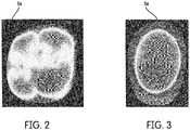
- the first type of mappings define distance maps respectively. Fig. 2 and Fig.
- each distance map may show the distance through colors, or numbers.
- the light grey scales show the deep fissures which lead to a long machining time due to the extensive use of a small dental tool for selective removal of rest material.
- the target geometry is simple and leads to a short machining time. Thus, the details of the target geometry have a large influence on the resulting machining time.
- the mappings alternatively comprise second type of mappings that have been obtained via simulation and describe the actual geometry of the rest dental blank (2') relative to the target geometry of the dental restoration/appliance after simulated completion of the corresponding machining processes.
- the second type of mappings describe the distance from the surface of the actual geometry of the rest dental blank (2') to the target geometry of the dental restoration/appliance or vice versa after simulated completion the corresponding machining process.
- the simulation may compute the distance from the target geometry to the actual one. These distances are obtained by simulation of the corresponding machining process.
- the surface of the actual geometry is described through triangulation with attributes including the simulated distances respectively.
- the second type of mappings define distance maps respectively obtained by simulation. Fig.
- FIG. 4 shows a greyscale distance map of the actual geometry of the rest dental blank (2') relative to the target geometry of the dental restoration/appliance, before simulated completion of the undercut machining processes.
- Fig. 5 shows a greyscale distance map of the actual geometry of the rest dental blank (2') relative to the target geometry of the dental restoration/appliance, after simulated completion of the undercut machining processes.
- the greyscale distance maps in Fig. 4 and Fig. 5 are obtained by simulation.
- the distance maps in Fig. 4 and Fig. 5 may show the simulated distances through colors or numbers.
- the light grey scales show the restoration/appliance-specific areas obtained by simulation of the undercut machining.
- control unit is adapted to train the artificial intelligence algorithm for predicting the machining time for manufacturing the dental restoration/appliance based on input data comprising: process parameters defining the said machining processes respectively; and mappings which include information on the target geometry of the dental restoration/appliance which are constructed based on the said machining processes respectively; and actual machining times required for completing the machining processes respectively.
- the artificial intelligence algorithm is based on a neural network, in particular a convolutional neural network.
- the convolutional neural network is able to learn geometry properties by means of training examples, which may require selective reworking by a thin dental tool (residual material removal). Furthermore, it may be possible to identify areas where only a slow feed is possible or where a special material immersion process (ZigZag) is required. These geometry dependent properties also have a large influence on the resulting machining time.
- the parameters of the neural network are learned through back-propagation.
Landscapes
- Health & Medical Sciences (AREA)
- Engineering & Computer Science (AREA)
- General Health & Medical Sciences (AREA)
- Animal Behavior & Ethology (AREA)
- Veterinary Medicine (AREA)
- Public Health (AREA)
- Life Sciences & Earth Sciences (AREA)
- Oral & Maxillofacial Surgery (AREA)
- Dentistry (AREA)
- Epidemiology (AREA)
- Manufacturing & Machinery (AREA)
- Physics & Mathematics (AREA)
- Human Computer Interaction (AREA)
- Automation & Control Theory (AREA)
- General Physics & Mathematics (AREA)
- Water Supply & Treatment (AREA)
- Dental Prosthetics (AREA)
- Dental Tools And Instruments Or Auxiliary Dental Instruments (AREA)
- Numerical Control (AREA)
Abstract
Description
- The present invention relates to a dental machining system which has a dental tool machine for manufacturing a dental restoration/appliance from a dental blank by using one or more dental tools. The present invention more particularly relates to a method of predicting the machining time for manufacturing a dental restoration or a dental appliance with the dental machining system.
- In general, a dental machining system has a dental tool machine for machining a dental blank which is typically made from ceramic. The dental tool machine generally has one or more driving units each movably holding at least one dental tool for machining the dental blank. The dental tools are respectively mounted to tool motors in the driving units. The dental tools can be exchanged after their service lifes are over. The dental blank is mounted to a dental blank holder which is relatively movable with respect to the dental tools. A control unit controls the operation of the dental tool machine. Generally, a CAD/CAM software runs on a PC connected to the control unit in the dental machining system. The CAD/CAM software is used to digitally construct a dental restoration/appliance and to provide a list of machining processes. The machining processes are used to generate the temporal trajectory of the dental tool in the dental tool machine. Usually, the machining time required for completing the machining processes are estimated before generating the temporal trajectory. Different estimation methods are known. According to a commonly known estimation method, first a rough estimation is conducted by using empirical values based on parameters such as the dental restoration/appliance class, the number of the caps in the dental restoration/appliance, the material of the dental blank, the degree of detail in the dental restoration/appliance, and the machining modes of the dental tool machine. Subsequently, a fine estimation is conducted based on the machining processes which are specifically identified for manufacturing the dental restoration/appliance. In the literature, machine learning methods are alternatively used to estimate the machining time. Reference can be made to the article of the authors Saric, T.; Simunovic, G.; Simunovic, K; & Svalina, I., titled "Estimation of Machining Time for CNC Manufacturing Using Neural Computing" published in the International Journal of Simulation Modelling. 15 (2016) 4, 663-675. In this method, process parameters of the machining processes are used as input data.
- In general, the differences in the geometries of the dental restoration/appliances complicates the estimation of the machining time. A typical factor that causes the estimation to become complicated is the need of selective removal of rest material from highly uneven, restoration/appliance-specific areas to be machined, in particular undercuts. Therefore, generally the machining time can only be estimated with poor accuracy.
- An objective of the present invention is to overcome the problems of the prior art and to provide a dental machining system for accurately predicting the machining time for manufacturing a dental restoration/appliance.
- This objective has been achieved through the dental machining system as defined in claim 1. The subject-matters of the dependent claims relate to further developments.
- The present invention provides a dental machining system for manufacturing a dental restoration/appliance. The dental machining system comprises a dental tool machine which comprises a dental blank holder for movably holding at least one dental blank relative to one or more dental tools; one or more driving units each for movably holding one or more dental tools; and a control unit for controlling the dental blank holder and the driving units based on construction data of the dental restoration/appliance and a plurality of machining processes specific for the manufacturing of the dental restoration/appliance from the dental blank. The control unit is further adapted to execute a trained artificial intelligence algorithm adapted to predict the machining time for manufacturing the dental restoration/appliance based on input data comprising: process parameters defining the machining processes respectively; and mappings which include information on the target geometry of the dental restoration/appliance, which are constructed based on the said machining processes respectively.
- A major advantageous effect of the present invention is that the dental machining system can accurately predict the machining time through the trained artificial intelligence algorithms with due consideration of the target geometry of the dental restoration/appliance. This makes it possible to accurately predict the machining time when selectively removing rest material from the restoration/appliance-specific areas to be machined, in particular undercuts. Another major advantageous effect of the present invention is that the artificial intelligence algorithm can be trained to adapt the prediction of the machining time to a change in the dental tool trajectory calculation schemes. Another major advantageous effect of the present invention is that the trained artificial intelligence algorithm based prediction may also take account of unknown factors influencing the machining time.
- According to the present invention different types of mappings may be used as input data. In an embodiment of the present invention, a first type of mapping is used to describe the target geometry of the dental restoration/appliance relative to the machining directions in the respective machining processes. The machining processes that are to be executed by the dental tool machine are preferably provided in a sequential list. Each machining process in the list also includes information on the process parameters that will be used to control the driving unit. For instance, each machining process in the list includes the machining direction relative to the target geometry of the dental restoration/appliance, and the type of the dental tool to be used. The machining directions are parallel to the dental tool. These first type of mappings preferably describe the distance from the surface of the dental restoration/appliance to a reference plane of the driving unit. Alternatively, the first type of mappings may preferably describe the distance from the surface of the dental blank to the surface of the dental restoration/appliance. The first type of mappings preferably define distance maps in two dimensions. Each distance map shows the distances through numerical values. Alternatively, colors or greyscales may be used. The input data may also include for each first type of mapping information on the type of the dental tool used for the corresponding machining process. Thanks to the first type of mappings, the amount of rest material can be determined based on the distance map and taken into consideration together preferably with the type of the dental tool by the trained artificial intelligence algorithm to predict the machining time.
- In an alternative embodiment of the present invention, second type of mappings are used as input data. The second type of mappings are obtained via simulation and describe the actual geometry of the rest dental blank relative to the target geometry of the dental restoration/appliance after simulated completion of the corresponding machining processes. Also, in this embodiment, the machining process that are to be executed by the dental tool machine are preferably provided in a sequential list. The actual geometry of the rest dental blank after completion of the corresponding machining process is found via simulation. The second type of mappings preferably describe the distance of the surface of the actual geometry of the rest dental blank to the target geometry of the dental restoration/appliance after simulated completion of the corresponding machining process. The second type of mappings preferably define distance maps in three dimensions. Also, in this embodiment, each distance map shows the simulated distances through numerical values. Alternatively, colors or greyscales may be used. The surface of the actual geometry is preferably described through triangulation with attributes including the simulated distances respectively. The attributes may be located at the vertices or the triangles.
- According to the present invention, the control unit of the dental machining system generates the input data based on the construction data of the dental restoration/appliance. Alternatively, the dental machining system may receive the input data and the construction data through an input means.
- According to an embodiment of the present invention, the dental machining system has a training mode and an inference mode. In the inference mode, the control unit executes the trained artificial intelligence algorithm for predicting the machining time. In the training mode, the control unit is adapted to train the artificial intelligence algorithm for predicting the machining time for manufacturing the dental restoration/appliance based on input data comprising: process parameters defining the said machining processes respectively; and mappings which include information on the target geometry of the dental restoration/appliance which are constructed based on the said machining processes respectively; and actual machining times required for completing the machining processes respectively. According to the present invention, the trained artificial intelligence algorithm is based on a neural network, preferably a convolutional neural network.
- In the training mode, the dental machining system uses previously generated or received input data derived from experimental or real manufacturing operations. The actual machining times are obtained by monitoring the machining processes. A database can be continually updated with such input data for the training mode.
- According to an embodiment of the present invention, the dental machining system may also have a CAD/CAM module which preferably includes a computer station such as a PC that runs a CAD/CAM software. The trained artificial intelligence algorithm is preferably provided as part of the CAD/CAM module. The CAD/CAM module is preferably external to the dental tool machine and accessible through a network or the like. A plurality of different dental tool machines may use the trained artificial intelligence algorithm for the inference. The CAD/CAM module may be also provided as part of the dental tool machine. The present invention also provides a CAD/CAM software for implementing the above mentioned functions of the dental machining system. The CAD/CAM software has computer-readable codes for causing a computerized dental machining system to execute the functions. The CAD/CAM software is stored in a computer-readable storage medium. The storage medium may be portable or integrated. The storage medium may be located external or internal to the dental machining system. The storage medium may be accessible through a network or the like. The present invention can be applied to dental tool machines with various types of kinematics for moving the dental blank and the dental tools.
- In the subsequent description, further aspects and advantageous effects of the present invention will be described in more detail by using exemplary embodiments and by reference to the drawings, wherein
-
Fig. 1 - is a schematic partial perspective view of a dental tool machine of the dental machining system according to an embodiment of the present invention; -
Fig. 2 - is a greyscale distance map, in two dimensions, of the dental restoration/appliance viewed along the machining direction parallel to the dental tool according to an embodiment of the present invention; -
Fig. 3 - is a greyscale distance map, in two dimensions, of the dental restoration/appliance viewed along the machining direction parallel to the dental tool according to another embodiment of the present invention; -
Fig. 4 - is a greyscale distance map of the actual geometry of the rest dental blank relative to the target geometry of the dental restoration/appliance, before simulated completion of an undercut machining process; -
Fig. 5 - is a greyscale distance map of the actual geometry of the rest dental blank relative to the target geometry of the dental restoration/appliance, after simulated completion of the undercut machining process. - The reference numbers shown in the drawings denote the elements as listed below and will be referred to in the subsequent description of the exemplary embodiments:
- 1.
- Dental tool machine
- 2.
- Dental blank
- 2'
- Rest dental blank
- 2a.
- Shaft
- 3.
- Dental tool
- 4.
- Driving unit
- 4a.
- Arm
- 4b.
- Shaft
- 5a., 5b.
- Greyscale distance maps
- X,Y,Z:
- Directions
-
Fig. 1 shows a dental machining system for manufacturing a dental restoration/appliance, comprising: a dental tool machine (1) which comprises: a dental blank holder for movably holding a dental blank (2) relative to the dental tools (3); two driving units (4) each for movably holding a dental tool (3), a control unit for controlling the dental blank holder and the driving units (4) based on construction data of the dental restoration/appliance and a plurality of machining processes specific for the manufacturing of the dental restoration/appliance from the dental blank (2). Each driving unit (4) has a shaft (4b) and an arm (4a) radially fixed to the shaft (4b). Each shaft (4b) can be moved in the z axis through a driving mechanism of the respective driving unit (4). Each arm (4a) can be moved around the z axis through the driving mechanism. The dental tools (3) are mounted to tool motors in the arm (4a) respectively. The dental blank (2) is joined to a shaft (2a) which can be moved along the y axis and rotated around the y axis through another driving mechanism. The control unit has a training mode and an inference mode. In the inference mode, the control unit is further adapted to execute a trained artificial intelligence algorithm adapted to predict the machining time for manufacturing the dental restoration/appliance based on input data comprising: process parameters defining the machining processes respectively; and mappings which include information on the target geometry of the dental restoration/appliance, which are constructed based on the said machining processes respectively. The process parameters comprise, for example, path distance, max feed, max acceleration and the like. The training mode will be described later. The control unit is adapted to generate the input data based on the construction data of the dental restoration/appliance. Alternatively, the input data and the construction data is input into the dental machining system through an input means. - In a first embodiment, the mappings comprise first type of mappings that describe the target geometry of the dental restoration/appliance relative to the machining directions (z) in said machining processes respectively. The input data also includes information on the type of the dental tool (3) used for the corresponding machining process. The machining directions (z) are parallel to the dental tool (3). The first type of mappings further describe the distance from the surface of the dental restoration/appliance to a reference plane of the driving unit (4) or the distance from the surface of the dental blank (2) to the surface of the dental restoration/appliance. The first type of mappings define distance maps respectively.
Fig. 2 and Fig. 3 each show a greyscale distance map in two dimensions of the dental restoration/appliance viewed from the machining direction parallel to the dental tool according to another embodiment of the present invention. Alternatively, each distance map may show the distance through colors, or numbers. InFig. 2 , the light grey scales show the deep fissures which lead to a long machining time due to the extensive use of a small dental tool for selective removal of rest material. InFig. 3 , the target geometry is simple and leads to a short machining time. Thus, the details of the target geometry have a large influence on the resulting machining time. - In a second embodiment, the mappings alternatively comprise second type of mappings that have been obtained via simulation and describe the actual geometry of the rest dental blank (2') relative to the target geometry of the dental restoration/appliance after simulated completion of the corresponding machining processes. The second type of mappings describe the distance from the surface of the actual geometry of the rest dental blank (2') to the target geometry of the dental restoration/appliance or vice versa after simulated completion the corresponding machining process. In particular, the simulation may compute the distance from the target geometry to the actual one. These distances are obtained by simulation of the corresponding machining process. The surface of the actual geometry is described through triangulation with attributes including the simulated distances respectively. The second type of mappings define distance maps respectively obtained by simulation.
Fig. 4 shows a greyscale distance map of the actual geometry of the rest dental blank (2') relative to the target geometry of the dental restoration/appliance, before simulated completion of the undercut machining processes.Fig. 5 shows a greyscale distance map of the actual geometry of the rest dental blank (2') relative to the target geometry of the dental restoration/appliance, after simulated completion of the undercut machining processes. The greyscale distance maps inFig. 4 and Fig. 5 are obtained by simulation. Alternatively, the distance maps inFig. 4 and Fig. 5 may show the simulated distances through colors or numbers. InFig. 5 , the light grey scales show the restoration/appliance-specific areas obtained by simulation of the undercut machining. - In the training mode, the control unit is adapted to train the artificial intelligence algorithm for predicting the machining time for manufacturing the dental restoration/appliance based on input data comprising: process parameters defining the said machining processes respectively; and mappings which include information on the target geometry of the dental restoration/appliance which are constructed based on the said machining processes respectively; and actual machining times required for completing the machining processes respectively.
- The artificial intelligence algorithm is based on a neural network, in particular a convolutional neural network. Regarding the distance maps of the dental restoration/appliance in combination with an indication of the dental tools used, the convolutional neural network is able to learn geometry properties by means of training examples, which may require selective reworking by a thin dental tool (residual material removal). Furthermore, it may be possible to identify areas where only a slow feed is possible or where a special material immersion process (ZigZag) is required. These geometry dependent properties also have a large influence on the resulting machining time. During the training of the neural network based artificial intelligence algorithm, the parameters of the neural network are learned through back-propagation.
Claims (14)
- A dental machining system for manufacturing a dental restoration/appliance, comprising:
a dental tool machine (1) which comprises:a dental blank holder for movably holding at least one dental blank (2) relative to one or more dental tools (3);one or more driving units (4) each for movably holding one or more dental tools (3),a control unit for controlling the dental blank holder and the driving units (4) based on construction data of the dental restoration/appliance and a plurality of machining processes specific for the manufacturing of the dental restoration/appliance from the dental blank (2);characterized in thatthe control unit is further adapted to executea trained artificial intelligence algorithm adapted to predict the machining time for manufacturing the dental restoration/appliance based on input data comprising:process parameters defining the machining processes respectively; andmappings which include information on the target geometry of the dental restoration/appliance, which are constructed based on the said machining processes respectively. - The dental machining system according to claim 1, characterized in that the mappings comprise: first type of mappings that describe the target geometry of the dental restoration/appliance relative to the machining directions (z) in said machining processes respectively, wherein the machining directions (z) are parallel to the dental tool (3).
- The dental machining system according to claim 2, characterized in that the first type of mappings further describe the distance from the surface of the target geometry of the dental restoration/appliance to a reference plane of the driving unit (4) or the distance from the surface of the dental blank (2) to the surface of the target geometry of the dental restorati on/appliance.
- The dental machining system according to claim 3, characterized in that the first type of mappings define distance maps respectively.
- The dental machining system according to claim 4, characterized in that each distance map shows the distance through colors, greyscales, or numbers.
- The dental machining system according to any one of claims 2 to 5, characterized in that the input data also includes for each first type of mapping information on the type of the dental tool (3) to be used in the corresponding machining process.
- The dental machining system according to claim 1, characterized in that the mappings comprise: second type of mappings that have been obtained via simulation, and describe the actual geometry of the rest dental blank (2') relative to the target geometry of the dental restoration/appliance after simulated completion of the corresponding machining processes.
- The dental machining system according to claim 7, characterized in that the second type of mappings describe the distance of the surface of the actual geometry of the rest dental blank (2') to the surface of the target geometry of the dental restoration/appliance or vice versa after simulated completion the corresponding machining processes.
- The dental machining system according to claim 8, characterized in that the surface of the actual geometry or target geometry is described through triangulation with attributes including the distances respectively.
- The dental machining system according to claim 8 or 9, characterized in that the second type of mappings define distance maps respectively.
- The dental machining system according to claim 10, characterized in that each distance map shows the distance through colors, greyscale, or numbers.
- The dental machining system according to any one of claims 1 to 11, characterized in that the control unit is adapted to generate the input data based on the construction data of the dental restoration/appliance.
- The dental machining system according to any one of claims 1 to 12, characterized by further comprising input means for receiving the input data and the construction data.
- The dental machining system according to any one of claims 1 to 13, characterized in that the control unit is adapted to train the artificial intelligence algorithm for predicting the machining time for manufacturing the dental restoration/appliance based on input data comprising:process parameters defining the said machining processes respectively; andmappings which include information on the target geometry of the dental restoration/appliance which are constructed based on the said machining processes respectively;and actual machining times required for completing the machining processes respectively.
Priority Applications (7)
| Application Number | Priority Date | Filing Date | Title |
|---|---|---|---|
| EP20154582.9A EP3859466B1 (en) | 2020-01-30 | 2020-01-30 | Dental machining system for predicting the machining time for manufacturing a dental restoration/appliance |
| JP2022542709A JP7589249B2 (en) | 2020-01-30 | 2021-01-29 | Dental machining system for predicting machining times for manufacturing dental restorations/appliances - Patent application |
| CN202180011725.9A CN114981740B (en) | 2020-01-30 | 2021-01-29 | Dental machining system for predicting machining time for manufacturing dental restorations/appliances |
| US17/795,156 US12402991B2 (en) | 2020-01-30 | 2021-01-29 | Dental machining system for predicting the machining time for manufacturing a dental restoration/appliance |
| CA3166313A CA3166313A1 (en) | 2020-01-30 | 2021-01-29 | Dental machining system for predicting the machining time for manufacturing a dental restoration/appliance |
| KR1020227021361A KR20220133863A (en) | 2020-01-30 | 2021-01-29 | Dental machining systems for predicting machining times to fabricate dental restorations/instruments |
| PCT/EP2021/052158 WO2021152125A1 (en) | 2020-01-30 | 2021-01-29 | Dental machining system for predicting the machining time for manufacturing a dental restoration/appliance |
Applications Claiming Priority (1)
| Application Number | Priority Date | Filing Date | Title |
|---|---|---|---|
| EP20154582.9A EP3859466B1 (en) | 2020-01-30 | 2020-01-30 | Dental machining system for predicting the machining time for manufacturing a dental restoration/appliance |
Publications (2)
| Publication Number | Publication Date |
|---|---|
| EP3859466A1 true EP3859466A1 (en) | 2021-08-04 |
| EP3859466B1 EP3859466B1 (en) | 2024-10-02 |
Family
ID=69411313
Family Applications (1)
| Application Number | Title | Priority Date | Filing Date |
|---|---|---|---|
| EP20154582.9A Active EP3859466B1 (en) | 2020-01-30 | 2020-01-30 | Dental machining system for predicting the machining time for manufacturing a dental restoration/appliance |
Country Status (7)
| Country | Link |
|---|---|
| US (1) | US12402991B2 (en) |
| EP (1) | EP3859466B1 (en) |
| JP (1) | JP7589249B2 (en) |
| KR (1) | KR20220133863A (en) |
| CN (1) | CN114981740B (en) |
| CA (1) | CA3166313A1 (en) |
| WO (1) | WO2021152125A1 (en) |
Cited By (1)
| Publication number | Priority date | Publication date | Assignee | Title |
|---|---|---|---|---|
| US12402991B2 (en) | 2020-01-30 | 2025-09-02 | Dentsply Sirona Inc. | Dental machining system for predicting the machining time for manufacturing a dental restoration/appliance |
Families Citing this family (6)
| Publication number | Priority date | Publication date | Assignee | Title |
|---|---|---|---|---|
| US11842484B2 (en) | 2021-01-04 | 2023-12-12 | James R. Glidewell Dental Ceramics, Inc. | Teeth segmentation using neural networks |
| US12136208B2 (en) | 2021-03-31 | 2024-11-05 | James R. Glidewell Dental Ceramics, Inc. | Automatic clean up of jaw scans |
| US12210802B2 (en) | 2021-04-30 | 2025-01-28 | James R. Glidewell Dental Ceramics, Inc. | Neural network margin proposal |
| US12201489B2 (en) * | 2021-09-01 | 2025-01-21 | Exocad Gmbh | Compensating deviations using a simulation of a manufacturing |
| US12295806B2 (en) | 2022-01-10 | 2025-05-13 | James R. Glidewell Dental Ceramics, Inc. | Automatic determination of trim-line for aligners |
| KR102805619B1 (en) * | 2022-12-01 | 2025-05-13 | 주식회사 휴비츠 | Method for predicting processing time of dental prosthesis |
Citations (4)
| Publication number | Priority date | Publication date | Assignee | Title |
|---|---|---|---|---|
| US5495430A (en) * | 1991-12-13 | 1996-02-27 | Kabushiki Kaisha Toyota Chuo Kenkyusho | Process time estimating apparatus |
| EP1088526A2 (en) * | 1999-10-01 | 2001-04-04 | Decim AB | Method and apparatus for the manufacturing of dental restorations |
| CN103235556A (en) * | 2013-03-27 | 2013-08-07 | 南京航空航天大学 | Feature-based numerical-control method for processing and manufacturing complicated parts |
| US20180028294A1 (en) * | 2016-07-27 | 2018-02-01 | James R. Glidewell Dental Ceramics, Inc. | Dental cad automation using deep learning |
Family Cites Families (10)
| Publication number | Priority date | Publication date | Assignee | Title |
|---|---|---|---|---|
| DE19922870A1 (en) | 1999-05-19 | 2000-12-07 | Paul Weigl | Automatic adjustment of dental restoration work comprises submitting CAD data to iterative process comprising analyzing properties of natural tooth, calculating required values, applying material to produce these and correcting |
| DE502004012224D1 (en) | 2003-04-04 | 2011-04-07 | Xawex Ag | Blank for the production of dental reconstructions and its production process |
| JP4815907B2 (en) | 2005-07-14 | 2011-11-16 | 株式会社ジェイテクト | Machining time prediction method and prediction device, and NC data editing device having machining time prediction function |
| US8562339B2 (en) * | 2007-07-13 | 2013-10-22 | 3M Innovative Properties Company | Digital orthodontic appliance coupling matrix |
| US8568897B2 (en) * | 2007-07-20 | 2013-10-29 | Ivoclar Vivadent Ag | Addressable matrices/cluster blanks for dental CAD/CAM systems and optimization thereof |
| JP5955798B2 (en) | 2013-03-18 | 2016-07-20 | イボクラール ビバデント アクチェンゲゼルシャフト | Addressable matrix / cluster blank for dental CAD / CAM system and its optimization |
| JP6627892B2 (en) | 2016-02-10 | 2020-01-08 | 富士通株式会社 | Dental technician manufacturing apparatus, method and program |
| JP6469065B2 (en) | 2016-10-28 | 2019-02-13 | ファナック株式会社 | Machine learning device and machining time prediction device |
| DE102017203475A1 (en) * | 2017-03-03 | 2018-09-06 | Sirona Dental Systems Gmbh | Method of constructing a restoration |
| EP3859466B1 (en) | 2020-01-30 | 2024-10-02 | DENTSPLY SIRONA Inc. | Dental machining system for predicting the machining time for manufacturing a dental restoration/appliance |
-
2020
- 2020-01-30 EP EP20154582.9A patent/EP3859466B1/en active Active
-
2021
- 2021-01-29 KR KR1020227021361A patent/KR20220133863A/en not_active Ceased
- 2021-01-29 US US17/795,156 patent/US12402991B2/en active Active
- 2021-01-29 CN CN202180011725.9A patent/CN114981740B/en active Active
- 2021-01-29 JP JP2022542709A patent/JP7589249B2/en active Active
- 2021-01-29 WO PCT/EP2021/052158 patent/WO2021152125A1/en not_active Ceased
- 2021-01-29 CA CA3166313A patent/CA3166313A1/en active Pending
Patent Citations (4)
| Publication number | Priority date | Publication date | Assignee | Title |
|---|---|---|---|---|
| US5495430A (en) * | 1991-12-13 | 1996-02-27 | Kabushiki Kaisha Toyota Chuo Kenkyusho | Process time estimating apparatus |
| EP1088526A2 (en) * | 1999-10-01 | 2001-04-04 | Decim AB | Method and apparatus for the manufacturing of dental restorations |
| CN103235556A (en) * | 2013-03-27 | 2013-08-07 | 南京航空航天大学 | Feature-based numerical-control method for processing and manufacturing complicated parts |
| US20180028294A1 (en) * | 2016-07-27 | 2018-02-01 | James R. Glidewell Dental Ceramics, Inc. | Dental cad automation using deep learning |
Non-Patent Citations (1)
| Title |
|---|
| SARIC, T.SIMUNOVIC, G.SIMUNOVIC, KSVALINA, I.: "Estimation of Machining Time for CNC Manufacturing Using Neural Computing", THE INTERNATIONAL JOURNAL OF SIMULATION MODELLING, vol. 15, no. 4, 2016, pages 663 - 675 |
Cited By (1)
| Publication number | Priority date | Publication date | Assignee | Title |
|---|---|---|---|---|
| US12402991B2 (en) | 2020-01-30 | 2025-09-02 | Dentsply Sirona Inc. | Dental machining system for predicting the machining time for manufacturing a dental restoration/appliance |
Also Published As
| Publication number | Publication date |
|---|---|
| WO2021152125A1 (en) | 2021-08-05 |
| CN114981740B (en) | 2025-06-06 |
| JP7589249B2 (en) | 2024-11-25 |
| KR20220133863A (en) | 2022-10-05 |
| EP3859466B1 (en) | 2024-10-02 |
| US12402991B2 (en) | 2025-09-02 |
| US20230057664A1 (en) | 2023-02-23 |
| CA3166313A1 (en) | 2021-08-05 |
| CN114981740A (en) | 2022-08-30 |
| JP2023518642A (en) | 2023-05-08 |
Similar Documents
| Publication | Publication Date | Title |
|---|---|---|
| US12402991B2 (en) | Dental machining system for predicting the machining time for manufacturing a dental restoration/appliance | |
| Suh et al. | A framework for an intelligent CNC and data model | |
| US8892255B2 (en) | Method for the automated programming and optimization of robotic work sequences | |
| EP3213161B1 (en) | Method for optimizing the productivity of a machining process of a cnc machine | |
| US7117056B2 (en) | CNC control unit with learning ability for machining centers | |
| US7099737B2 (en) | Intelligent STEP-NC controller | |
| JP2019082836A (en) | Tool life prediction device | |
| JP2017033138A (en) | Machine tool, simulation apparatus, and machine learning device | |
| KR20220092865A (en) | Dental machining systems for predicting wear conditions on dental tools | |
| US12616560B2 (en) | Dental machining system for generating process parameters of the machining | |
| CN107390640A (en) | Numerical control device | |
| Zhang et al. | A design for a novel open, intelligent and integrated CNC system based on ISO 10303-238 and PMAC | |
| Amouzgar et al. | Smart process planning of crankshaft machining through multiple objectives optimization | |
| KR102860009B1 (en) | Computer numerical control capable of limiting machining error and method of computer numerical control using the same | |
| Balic | Neural-network-based numerical control for milling machine | |
| Caniglia | End-effector tools wear prediction: interaction with the workpiece modelling in a quasi-FEM approach | |
| Živanović et al. | Machine tools and industry 4.0-trends of development | |
| Pansica | End-effector tools wear prediction: analysis and modelling of a CNC machine and new formulation of the friction coefficient | |
| Westkamper | Technical Intelligence in the Manufacturing of the Future |
Legal Events
| Date | Code | Title | Description |
|---|---|---|---|
| PUAI | Public reference made under article 153(3) epc to a published international application that has entered the european phase |
Free format text: ORIGINAL CODE: 0009012 |
|
| STAA | Information on the status of an ep patent application or granted ep patent |
Free format text: STATUS: THE APPLICATION HAS BEEN PUBLISHED |
|
| AK | Designated contracting states |
Kind code of ref document: A1 Designated state(s): AL AT BE BG CH CY CZ DE DK EE ES FI FR GB GR HR HU IE IS IT LI LT LU LV MC MK MT NL NO PL PT RO RS SE SI SK SM TR |
|
| STAA | Information on the status of an ep patent application or granted ep patent |
Free format text: STATUS: REQUEST FOR EXAMINATION WAS MADE |
|
| 17P | Request for examination filed |
Effective date: 20220117 |
|
| RBV | Designated contracting states (corrected) |
Designated state(s): AL AT BE BG CH CY CZ DE DK EE ES FI FR GB GR HR HU IE IS IT LI LT LU LV MC MK MT NL NO PL PT RO RS SE SI SK SM TR |
|
| P01 | Opt-out of the competence of the unified patent court (upc) registered |
Effective date: 20230524 |
|
| STAA | Information on the status of an ep patent application or granted ep patent |
Free format text: STATUS: EXAMINATION IS IN PROGRESS |
|
| 17Q | First examination report despatched |
Effective date: 20231018 |
|
| GRAP | Despatch of communication of intention to grant a patent |
Free format text: ORIGINAL CODE: EPIDOSNIGR1 |
|
| STAA | Information on the status of an ep patent application or granted ep patent |
Free format text: STATUS: GRANT OF PATENT IS INTENDED |
|
| RIC1 | Information provided on ipc code assigned before grant |
Ipc: A61C 5/77 20170101ALN20240502BHEP Ipc: A61C 13/00 20060101ALI20240502BHEP Ipc: G05B 19/4099 20060101AFI20240502BHEP |
|
| INTG | Intention to grant announced |
Effective date: 20240527 |
|
| GRAS | Grant fee paid |
Free format text: ORIGINAL CODE: EPIDOSNIGR3 |
|
| GRAA | (expected) grant |
Free format text: ORIGINAL CODE: 0009210 |
|
| STAA | Information on the status of an ep patent application or granted ep patent |
Free format text: STATUS: THE PATENT HAS BEEN GRANTED |
|
| AK | Designated contracting states |
Kind code of ref document: B1 Designated state(s): AL AT BE BG CH CY CZ DE DK EE ES FI FR GB GR HR HU IE IS IT LI LT LU LV MC MK MT NL NO PL PT RO RS SE SI SK SM TR |
|
| REG | Reference to a national code |
Ref country code: GB Ref legal event code: FG4D |
|
| REG | Reference to a national code |
Ref country code: CH Ref legal event code: EP |
|
| REG | Reference to a national code |
Ref country code: IE Ref legal event code: FG4D |
|
| REG | Reference to a national code |
Ref country code: DE Ref legal event code: R096 Ref document number: 602020038558 Country of ref document: DE |
|
| REG | Reference to a national code |
Ref country code: LT Ref legal event code: MG9D |
|
| REG | Reference to a national code |
Ref country code: NL Ref legal event code: MP Effective date: 20241002 |
|
| PG25 | Lapsed in a contracting state [announced via postgrant information from national office to epo] |
Ref country code: NL Free format text: LAPSE BECAUSE OF FAILURE TO SUBMIT A TRANSLATION OF THE DESCRIPTION OR TO PAY THE FEE WITHIN THE PRESCRIBED TIME-LIMIT Effective date: 20241002 |
|
| PG25 | Lapsed in a contracting state [announced via postgrant information from national office to epo] |
Ref country code: NL Free format text: LAPSE BECAUSE OF FAILURE TO SUBMIT A TRANSLATION OF THE DESCRIPTION OR TO PAY THE FEE WITHIN THE PRESCRIBED TIME-LIMIT Effective date: 20241002 |
|
| PG25 | Lapsed in a contracting state [announced via postgrant information from national office to epo] |
Ref country code: IS Free format text: LAPSE BECAUSE OF FAILURE TO SUBMIT A TRANSLATION OF THE DESCRIPTION OR TO PAY THE FEE WITHIN THE PRESCRIBED TIME-LIMIT Effective date: 20250202 Ref country code: HR Free format text: LAPSE BECAUSE OF FAILURE TO SUBMIT A TRANSLATION OF THE DESCRIPTION OR TO PAY THE FEE WITHIN THE PRESCRIBED TIME-LIMIT Effective date: 20241002 Ref country code: PT Free format text: LAPSE BECAUSE OF FAILURE TO SUBMIT A TRANSLATION OF THE DESCRIPTION OR TO PAY THE FEE WITHIN THE PRESCRIBED TIME-LIMIT Effective date: 20250203 |
|
| PG25 | Lapsed in a contracting state [announced via postgrant information from national office to epo] |
Ref country code: FI Free format text: LAPSE BECAUSE OF FAILURE TO SUBMIT A TRANSLATION OF THE DESCRIPTION OR TO PAY THE FEE WITHIN THE PRESCRIBED TIME-LIMIT Effective date: 20241002 |
|
| PG25 | Lapsed in a contracting state [announced via postgrant information from national office to epo] |
Ref country code: BG Free format text: LAPSE BECAUSE OF FAILURE TO SUBMIT A TRANSLATION OF THE DESCRIPTION OR TO PAY THE FEE WITHIN THE PRESCRIBED TIME-LIMIT Effective date: 20241002 |
|
| PG25 | Lapsed in a contracting state [announced via postgrant information from national office to epo] |
Ref country code: ES Free format text: LAPSE BECAUSE OF FAILURE TO SUBMIT A TRANSLATION OF THE DESCRIPTION OR TO PAY THE FEE WITHIN THE PRESCRIBED TIME-LIMIT Effective date: 20241002 |
|
| PG25 | Lapsed in a contracting state [announced via postgrant information from national office to epo] |
Ref country code: NO Free format text: LAPSE BECAUSE OF FAILURE TO SUBMIT A TRANSLATION OF THE DESCRIPTION OR TO PAY THE FEE WITHIN THE PRESCRIBED TIME-LIMIT Effective date: 20250102 |
|
| PG25 | Lapsed in a contracting state [announced via postgrant information from national office to epo] |
Ref country code: LV Free format text: LAPSE BECAUSE OF FAILURE TO SUBMIT A TRANSLATION OF THE DESCRIPTION OR TO PAY THE FEE WITHIN THE PRESCRIBED TIME-LIMIT Effective date: 20241002 Ref country code: GR Free format text: LAPSE BECAUSE OF FAILURE TO SUBMIT A TRANSLATION OF THE DESCRIPTION OR TO PAY THE FEE WITHIN THE PRESCRIBED TIME-LIMIT Effective date: 20250103 |
|
| PG25 | Lapsed in a contracting state [announced via postgrant information from national office to epo] |
Ref country code: PL Free format text: LAPSE BECAUSE OF FAILURE TO SUBMIT A TRANSLATION OF THE DESCRIPTION OR TO PAY THE FEE WITHIN THE PRESCRIBED TIME-LIMIT Effective date: 20241002 Ref country code: CZ Free format text: LAPSE BECAUSE OF FAILURE TO SUBMIT A TRANSLATION OF THE DESCRIPTION OR TO PAY THE FEE WITHIN THE PRESCRIBED TIME-LIMIT Effective date: 20241002 |
|
| PG25 | Lapsed in a contracting state [announced via postgrant information from national office to epo] |
Ref country code: RS Free format text: LAPSE BECAUSE OF FAILURE TO SUBMIT A TRANSLATION OF THE DESCRIPTION OR TO PAY THE FEE WITHIN THE PRESCRIBED TIME-LIMIT Effective date: 20250102 |
|
| PG25 | Lapsed in a contracting state [announced via postgrant information from national office to epo] |
Ref country code: SM Free format text: LAPSE BECAUSE OF FAILURE TO SUBMIT A TRANSLATION OF THE DESCRIPTION OR TO PAY THE FEE WITHIN THE PRESCRIBED TIME-LIMIT Effective date: 20241002 |
|
| REG | Reference to a national code |
Ref country code: DE Ref legal event code: R097 Ref document number: 602020038558 Country of ref document: DE |
|
| PG25 | Lapsed in a contracting state [announced via postgrant information from national office to epo] |
Ref country code: DK Free format text: LAPSE BECAUSE OF FAILURE TO SUBMIT A TRANSLATION OF THE DESCRIPTION OR TO PAY THE FEE WITHIN THE PRESCRIBED TIME-LIMIT Effective date: 20241002 |
|
| PG25 | Lapsed in a contracting state [announced via postgrant information from national office to epo] |
Ref country code: EE Free format text: LAPSE BECAUSE OF FAILURE TO SUBMIT A TRANSLATION OF THE DESCRIPTION OR TO PAY THE FEE WITHIN THE PRESCRIBED TIME-LIMIT Effective date: 20241002 |
|
| PG25 | Lapsed in a contracting state [announced via postgrant information from national office to epo] |
Ref country code: RO Free format text: LAPSE BECAUSE OF FAILURE TO SUBMIT A TRANSLATION OF THE DESCRIPTION OR TO PAY THE FEE WITHIN THE PRESCRIBED TIME-LIMIT Effective date: 20241002 |
|
| PG25 | Lapsed in a contracting state [announced via postgrant information from national office to epo] |
Ref country code: SK Free format text: LAPSE BECAUSE OF FAILURE TO SUBMIT A TRANSLATION OF THE DESCRIPTION OR TO PAY THE FEE WITHIN THE PRESCRIBED TIME-LIMIT Effective date: 20241002 |
|
| PG25 | Lapsed in a contracting state [announced via postgrant information from national office to epo] |
Ref country code: IT Free format text: LAPSE BECAUSE OF FAILURE TO SUBMIT A TRANSLATION OF THE DESCRIPTION OR TO PAY THE FEE WITHIN THE PRESCRIBED TIME-LIMIT Effective date: 20241002 |
|
| PLBE | No opposition filed within time limit |
Free format text: ORIGINAL CODE: 0009261 |
|
| STAA | Information on the status of an ep patent application or granted ep patent |
Free format text: STATUS: NO OPPOSITION FILED WITHIN TIME LIMIT |
|
| PG25 | Lapsed in a contracting state [announced via postgrant information from national office to epo] |
Ref country code: SE Free format text: LAPSE BECAUSE OF FAILURE TO SUBMIT A TRANSLATION OF THE DESCRIPTION OR TO PAY THE FEE WITHIN THE PRESCRIBED TIME-LIMIT Effective date: 20241002 |
|
| 26N | No opposition filed |
Effective date: 20250703 |
|
| PG25 | Lapsed in a contracting state [announced via postgrant information from national office to epo] |
Ref country code: MC Free format text: LAPSE BECAUSE OF FAILURE TO SUBMIT A TRANSLATION OF THE DESCRIPTION OR TO PAY THE FEE WITHIN THE PRESCRIBED TIME-LIMIT Effective date: 20241002 Ref country code: LU Free format text: LAPSE BECAUSE OF NON-PAYMENT OF DUE FEES Effective date: 20250130 |
|
| REG | Reference to a national code |
Ref country code: AT Ref legal event code: UEP Ref document number: 1728927 Country of ref document: AT Kind code of ref document: T Effective date: 20241002 |
|
| PG25 | Lapsed in a contracting state [announced via postgrant information from national office to epo] |
Ref country code: BE Free format text: LAPSE BECAUSE OF NON-PAYMENT OF DUE FEES Effective date: 20250131 |
|
| REG | Reference to a national code |
Ref country code: BE Ref legal event code: MM Effective date: 20250131 |
|
| PGFP | Annual fee paid to national office [announced via postgrant information from national office to epo] |
Ref country code: GB Payment date: 20251220 Year of fee payment: 7 |
|
| PGFP | Annual fee paid to national office [announced via postgrant information from national office to epo] |
Ref country code: FR Payment date: 20251218 Year of fee payment: 7 |
|
| PG25 | Lapsed in a contracting state [announced via postgrant information from national office to epo] |
Ref country code: IE Free format text: LAPSE BECAUSE OF NON-PAYMENT OF DUE FEES Effective date: 20250130 |
|
| REG | Reference to a national code |
Ref country code: CH Ref legal event code: U11 Free format text: ST27 STATUS EVENT CODE: U-0-0-U10-U11 (AS PROVIDED BY THE NATIONAL OFFICE) Effective date: 20260201 |
|
| PGFP | Annual fee paid to national office [announced via postgrant information from national office to epo] |
Ref country code: DE Payment date: 20251217 Year of fee payment: 7 |
|
| PGFP | Annual fee paid to national office [announced via postgrant information from national office to epo] |
Ref country code: AT Payment date: 20251218 Year of fee payment: 7 |
|
| PGFP | Annual fee paid to national office [announced via postgrant information from national office to epo] |
Ref country code: CH Payment date: 20260201 Year of fee payment: 7 |
|
| PG25 | Lapsed in a contracting state [announced via postgrant information from national office to epo] |
Ref country code: CY Free format text: LAPSE BECAUSE OF FAILURE TO SUBMIT A TRANSLATION OF THE DESCRIPTION OR TO PAY THE FEE WITHIN THE PRESCRIBED TIME-LIMIT Effective date: 20241002 |
|
| PG25 | Lapsed in a contracting state [announced via postgrant information from national office to epo] |
Ref country code: TR Free format text: LAPSE BECAUSE OF FAILURE TO SUBMIT A TRANSLATION OF THE DESCRIPTION OR TO PAY THE FEE WITHIN THE PRESCRIBED TIME-LIMIT Effective date: 20241002 |
|
| PG25 | Lapsed in a contracting state [announced via postgrant information from national office to epo] |
Ref country code: LT Free format text: LAPSE BECAUSE OF FAILURE TO SUBMIT A TRANSLATION OF THE DESCRIPTION OR TO PAY THE FEE WITHIN THE PRESCRIBED TIME-LIMIT Effective date: 20241002 |