EP3859356A1 - Electric field sensor - Google Patents
Electric field sensor Download PDFInfo
- Publication number
- EP3859356A1 EP3859356A1 EP19867019.2A EP19867019A EP3859356A1 EP 3859356 A1 EP3859356 A1 EP 3859356A1 EP 19867019 A EP19867019 A EP 19867019A EP 3859356 A1 EP3859356 A1 EP 3859356A1
- Authority
- EP
- European Patent Office
- Prior art keywords
- electric field
- signal
- electric
- light
- electro
- Prior art date
- Legal status (The legal status is an assumption and is not a legal conclusion. Google has not performed a legal analysis and makes no representation as to the accuracy of the status listed.)
- Granted
Links
Images



Classifications
-
- G—PHYSICS
- G01—MEASURING; TESTING
- G01R—MEASURING ELECTRIC VARIABLES; MEASURING MAGNETIC VARIABLES
- G01R29/00—Arrangements for measuring or indicating electric quantities not covered by groups G01R19/00 - G01R27/00
- G01R29/08—Measuring electromagnetic field characteristics
- G01R29/0864—Measuring electromagnetic field characteristics characterised by constructional or functional features
- G01R29/0878—Sensors; antennas; probes; detectors
- G01R29/0885—Sensors; antennas; probes; detectors using optical probes, e.g. electro-optical, luminescent, glow discharge, or optical interferometers
-
- G—PHYSICS
- G01—MEASURING; TESTING
- G01R—MEASURING ELECTRIC VARIABLES; MEASURING MAGNETIC VARIABLES
- G01R35/00—Testing or calibrating of apparatus covered by the other groups of this subclass
- G01R35/005—Calibrating; Standards or reference devices, e.g. voltage or resistance standards, "golden" references
-
- G—PHYSICS
- G02—OPTICS
- G02F—OPTICAL DEVICES OR ARRANGEMENTS FOR THE CONTROL OF LIGHT BY MODIFICATION OF THE OPTICAL PROPERTIES OF THE MEDIA OF THE ELEMENTS INVOLVED THEREIN; NON-LINEAR OPTICS; FREQUENCY-CHANGING OF LIGHT; OPTICAL LOGIC ELEMENTS; OPTICAL ANALOGUE/DIGITAL CONVERTERS
- G02F1/00—Devices or arrangements for the control of the intensity, colour, phase, polarisation or direction of light arriving from an independent light source, e.g. switching, gating or modulating; Non-linear optics
- G02F1/01—Devices or arrangements for the control of the intensity, colour, phase, polarisation or direction of light arriving from an independent light source, e.g. switching, gating or modulating; Non-linear optics for the control of the intensity, phase, polarisation or colour
- G02F1/03—Devices or arrangements for the control of the intensity, colour, phase, polarisation or direction of light arriving from an independent light source, e.g. switching, gating or modulating; Non-linear optics for the control of the intensity, phase, polarisation or colour based on ceramics or electro-optical crystals, e.g. exhibiting Pockels effect or Kerr effect
- G02F1/0305—Constructional arrangements
-
- G—PHYSICS
- G02—OPTICS
- G02F—OPTICAL DEVICES OR ARRANGEMENTS FOR THE CONTROL OF LIGHT BY MODIFICATION OF THE OPTICAL PROPERTIES OF THE MEDIA OF THE ELEMENTS INVOLVED THEREIN; NON-LINEAR OPTICS; FREQUENCY-CHANGING OF LIGHT; OPTICAL LOGIC ELEMENTS; OPTICAL ANALOGUE/DIGITAL CONVERTERS
- G02F1/00—Devices or arrangements for the control of the intensity, colour, phase, polarisation or direction of light arriving from an independent light source, e.g. switching, gating or modulating; Non-linear optics
- G02F1/01—Devices or arrangements for the control of the intensity, colour, phase, polarisation or direction of light arriving from an independent light source, e.g. switching, gating or modulating; Non-linear optics for the control of the intensity, phase, polarisation or colour
- G02F1/21—Devices or arrangements for the control of the intensity, colour, phase, polarisation or direction of light arriving from an independent light source, e.g. switching, gating or modulating; Non-linear optics for the control of the intensity, phase, polarisation or colour by interference
- G02F1/225—Devices or arrangements for the control of the intensity, colour, phase, polarisation or direction of light arriving from an independent light source, e.g. switching, gating or modulating; Non-linear optics for the control of the intensity, phase, polarisation or colour by interference in an optical waveguide structure
Definitions
- the present invention relates to an electric field sensor.
- a sensor element made of a metal such as a general dipole antenna is generally used.
- electro-optic effect is an effect in which, when an electric field is applied to an electro-optic crystal, a refractive index of light passing through the electro-optic crystal changes in proportion to an electric field intensity. A change in the refractive index causes a phase change in a light wave passing through the optical crystal.
- an electric field applied to an electro-optic crystal can be measured by measuring a change in phase (see, for example, Patent Literatures 1 and 2).
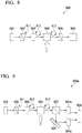
- FIG. 8 is a diagram showing a configuration example of a conventional electric field sensor utilizing an electro-optic effect.
- an electric field sensor 900 includes a light source 901, a polarizer 902, a wavelength plate 903, an electro-optic crystal 904, a polarizer 905, and a light receiver 906.
- the light source 901 is, for example, a semiconductor laser.
- the polarizer 902 emits linearly polarized light (reference sign 911) among light beams incident from the light source 901.
- the wavelength plate 903 is a ⁇ /4 wavelength plate and polarizes the light beams incident from the polarizer 902 into circularly polarized light (reference sign 912) to emit it.
- the electro-optic crystal 904 changes a polarization state due to a change in birefringence according to an electric field intensity applied by an external electric field source.
- the electro-optic crystal 904 emits a light beam of elliptically polarized light (reference sign 913) whose polarization state has changed.
- the polarizer 905 converts the light beam emitted by the electro-optic crystal 904 into linearly polarized light.
- the light receiver 906 converts the light beam emitted by the polarizer 905 into an electric signal and outputs it.
- the reason why the wavelength plate 903 is used is to prevent a detection sensitivity of the same birefringent component as a polarization axis of the light source from decreasing when linearly polarized light is incident on the electro-optic crystal 904, and because it is necessary to use circularly polarized light to determine a polarity of the electric field.
- an electric field intensity to be measured is converted into an electric intensity by converting a change in light intensity into a light receiver electric signal (see, for example, Non-Patent Literature 1).
- a measured value may vary due to a change in an amount of light from the light source.
- a polarization beam splitter is disposed instead of the polarizer after an output of the electro-optic crystal to reduce the variation.
- Fig. 9 is a diagram showing a configuration example in which a polarization beam splitter is disposed instead of an analyzer (the polarizer 905) after an output of the electro-optic crystal 904. As shown in Fig.
- an electric field sensor 900A includes a light source 901, a polarizer 902, a wavelength plate 903, an electro-optic crystal 904, a beam splitter 907, a mirror 908, a first light receiver 906a, a second light receiver 906b, and a differential amplifier 909.
- the beam splitter 907 is a polarization beam splitter and separates incident light into a horizontal polarization component P P and a vertical polarization component Ps.
- the first light receiver 906a converts the horizontal polarization component P P into an electric signal.
- the second light receiver 906b converts the vertical polarization component P S that has been totally reflected by the mirror into an electric signal.
- the differential amplifier 909 performs differential output of the two component signals output from the first light receiver 906a and the second light receiver 906b. With this configuration, common variation components such as light source variation are removed (see, for example, Non-Patent Literature 2).
- ⁇ n is a refractive index change
- n is an unperturbed refractive index
- E is an electric field intensity
- r eff is a linear electro-optic coefficient
- ⁇ is a phase change
- L is a crystal length
- d is a crystal thickness
- ⁇ is a wavelength
- an optical power intensity P out output from the analyzer (polarizer 905) is represented by the following expression (3).
- P out P in ⁇ 1 + sin ⁇ ⁇ / 2
- P out is the optical power intensity output from the analyzer (polarizer 905)
- P in is optical power input to the electro-optic crystal.
- a magnitude of an amount of phase change with respect to an electric field of an optical crystal that is, a linear electro-optic constant r eff corresponding to a sensitivity, changes according to a temperature dependence of birefringence of the optical crystal.
- a phase change is added to the linear electro-optic constant r eff due to a change in a polarized wave state in the crystal caused by stress such as extension and contraction of an electro-optical action length of the crystal due to a thermal expansion coefficient of a material of the optical crystal, and thereby a sensor output varies due to factors other than an electric field to be measured, and the variation amount is added to an original measurement output, resulting in a decrease in measurement stability.
- a decrease in detection sensitivity is also a variation factor of the sensitivity to the electric field intensity.
- a polarization beam splitter also has temperature dependence, a ratio between a P-wave component and an S-wave component that are separated changes.
- Non-Patent Literature 2 Due to these variation factors, even when branching is performed at a polarization beam splitter to configure a differential optical system so that a temporal variation in intensity of a light source is cancelled as in the technology described in Non-Patent Literature 2, it is not easy to cancel the temperature-dependent factors of the entire sensor and perform highly stable electric field measurement.
- One aspect of the present invention provides an electric field sensor that utilizes an electro-optic effect and can measure an electric field intensity without impairing measurement stability even when an ambient temperature or the like changes.
- An electric field sensor (100, 100A, 100A', 100C, 100D) according to one aspect of the present invention is an electric field sensor which measures an electric field generated by a target utilizing an electro-optic effect and includes a light source (1), an electro-optic crystal (5, 5D) on which light in a predetermined polarization state emitted from the light source is incident and which is subjected to an electric field generated by the target, a reference electric field applicator (reference power supply 11, electric field controller 15, reference electric field source 16) configured to apply an electric field based on a reference signal with a known signal level to the electro-optic crystal, a light receiver (1021) configured to receive light emitted from the electro-optic crystal and to convert the received light into an electric signal, and a separation corrector (1022, 1022A) configured to separate the electric signal into a measurement signal based on the electric field generated by the target and the reference signal and to correct a signal level of the measurement signal on the basis of the signal level of the separated reference signal.
- the electric field sensor can monitor an amount of change in a linear electro-optic constant r eff by applying an electric field based on the reference signal with a known signal level to the electro-optic crystal and detecting a change in the linear electro-optic constant r eff only with the reference signal at a second separator.
- the electric field sensor utilizes an electro-optic effect and can measure the electric field intensity without impairing measurement stability even when an ambient temperature or the like changes.
- the separation corrector may include a first separator (a filter 10) configured to separate the measurement signal from the electric signal, a second separator (a lock-in amplifier 12) configured to separate the reference signal from the electric signal, and a corrector (a gain controller 13, a variable gain amplifier 14) configured to correct the signal level of the measurement signal on the basis of the signal level of the separated reference signal.
- the electric field sensor can obtain the amount of phase change induced by the electric field intensity applied to the electro-optic crystal.
- the electric field sensor may further include a measurement electric field applicator (measurement power supply 21, measurement electric field controller 22) configured to apply a referential signal with a known signal level to the target
- the separation corrector may include a first separator (lock-in amplifier 12a) configured to separate the measurement signal on which the referential signal is superimposed from the electric signal, a second separator (lock-in amplifier 12b) configured to separate the reference signal from the electric signal, and a corrector (gain controller 13, variable gain amplifier 14) configured to correct the signal level of the measurement signal on the basis of the signal level of the separated reference signal.
- the electric field sensor is configured such that the referential signal is superimposed on the measurement signal by applying the electric field based on the referential signal to the electric field generated by the target, and the first separator separates the measurement signal on which the referential signal is superimposed from the electric signal.
- the electric field sensor can remove these noise components with the above-described configuration.
- the electric field sensor can measure the electric field intensity with high accuracy even when an electric field intensity to be measured is small and a signal to noise (SN) ratio is poor.
- the target may be a solar cell (201)
- the light source solar cell irradiation light source 24
- the electro-optic crystal may be subjected to an electric field generated by the solar cell irradiated with the light from the light source as an electric field generated by the target.
- the electric field sensor can measure the electric field generated by irradiating the solar cell with light. Therefore, with the configuration described above, since an electric field sensitivity of the electric field sensor can be corrected using the reference signal even when an ambient temperature changes, highly stable measurement is possible.
- the electro-optic crystal may include a first optical waveguide (3031) on which light of the light source is incident, a first electrode (3033) which is connected to a first output of the first optical waveguide and to which the electric field generated by the target is input, a second electrode (3034) which is connected to the first electrode and to which the electric field based on the reference signal is applied, a third electrode (3032) connected to a first output of the first optical waveguide and grounded, and a second optical waveguide (3035) having a first input to which the second electrode is connected, a second input to which the third electrode is connected, and an output connected to the light receiver.
- the electric field sensor can monitor a phase change with respect to a temperature change by applying the electric field based on the reference signal even in the electric field sensor of an optical waveguide-type.
- the electric field sensor may further include a transparent electrode (ITO electrode 5D1) disposed on a first surface of the electro-optic crystal (5D), and a mirror (5D2) disposed on a second surface of the electro-optic crystal facing the first surface, light emitted from the light source may be incident from the transparent electrode, the light incident from the transparent electrode may be reflected by the mirror, and the reflected light may be emitted from the transparent electrode.
- ITO electrode 5D1 disposed on a first surface of the electro-optic crystal (5D)
- a mirror (5D2) disposed on a second surface of the electro-optic crystal facing the first surface
- the electric field sensor measures an electric field intensity by acquiring a phase change of light when a light beam is reflected by the mirror and returned through the transparent electrode.
- the electric field sensor can monitor a phase change with respect to a temperature change by applying the electric field based on the reference even when a phase change occurs with respect to the electric field applied to the transparent electrode and a lower surface of the crystal.
- the predetermined polarization state may be circularly polarized light.
- the electric field sensor can determine a polarity of the electric field using the circularly polarized light.
- a frequency of the reference signal may be in a frequency band that does not affect the measurement signal.
- the electric field sensor is configured such that the reference signal intensity does not affect the measurement signal, it is possible to provide an electric field sensor with high measurement stability.
- the light receiver may include a polarization beam splitter configured to separate circularly polarized light emitted from the electro-optic crystal into P-polarized light and S-polarized light, and a differential amplifier configured to amplify a differential component of electric signals of the P-polarized light and the S-polarized light separated by the polarization beam splitter and to output the amplified electric signal to the separation corrector.
- a polarization beam splitter configured to separate circularly polarized light emitted from the electro-optic crystal into P-polarized light and S-polarized light
- a differential amplifier configured to amplify a differential component of electric signals of the P-polarized light and the S-polarized light separated by the polarization beam splitter and to output the amplified electric signal to the separation corrector.
- the electric field sensor utilizes an electro-optic effect and can measure the electric field intensity without impairing measurement stability even when an ambient temperature or the like changes.
- the separation corrector may include a filter configured to remove a signal component of the electric field based on the reference signal in the electric signal output from the differential amplifier, an amplifier configured to extract a signal component of the electric field based on the reference signal in the electric signal output from the differential amplifier using the reference signal, a gain controller configured to generate a control signal that controls an amplification factor according to the signal component of the electric field based on the reference signal output from the amplifier, and a variable gain amplifier configured to vary an amplification factor of the electric signal output from the filter in which the signal component of the electric field based on the reference signal is removed according to the control signal output from the gain controller, and to output the electric signal.
- a filter configured to remove a signal component of the electric field based on the reference signal in the electric signal output from the differential amplifier
- an amplifier configured to extract a signal component of the electric field based on the reference signal in the electric signal output from the differential amplifier using the reference signal
- a gain controller configured to generate a control signal that controls an amplification factor according to the signal component
- the electric field sensor utilizes an electro-optic effect and can measure the electric field intensity without impairing measurement stability even when an ambient temperature or the like changes.
- the electric field sensor may further include a measurement electric field applicator configured to apply a referential signal with a known signal level to the target
- the light receiver may include a polarization beam splitter configured to separate circularly polarized light emitted from the electro-optic crystal into P-polarized light and S-polarized light, and a differential amplifier configured to amplify a differential component of electric signals of the P-polarized light and the S-polarized light separated by the polarization beam splitter and to output the amplified electric signal to the separation corrector.
- the electric field sensor when there is capacitive coupling noise from the power supply or noise due to electromagnetic induction or the like in the surroundings in addition to the electric field to be measured, the electric field sensor can remove these noise components with the above-described configuration. As a result, the electric field sensor can measure the electric field intensity with high accuracy even when an electric field intensity to be measured is small and the SN ratio is poor.
- the separation corrector may include a first amplifier configured to extract a signal component of an electric field based on the measurement signal in an electric signal output from the differential amplifier using the measurement signal, a second amplifier configured to extract a signal component of an electric field based on the reference signal in an electric signal output from the differential amplifier using the reference signal, a gain controller configured to generate a control signal that controls an amplification factor according to a signal component of the electric field based on the reference signal output from the second amplifier, and a variable gain amplifier configured to vary an amplification factor of the electric signal of the signal component of the electric field based on the measurement signal output from the first amplifier according to the control signal output from the gain controller, and to output the electric signal.
- the electric field sensor when there is capacitive coupling noise from the power supply or noise due to electromagnetic induction or the like in the surroundings in addition to the electric field to be measured, the electric field sensor can remove these noise components with the above-described configuration. As a result, the electric field sensor can measure the electric field intensity with high accuracy even when an electric field intensity to be measured is small and the SN ratio is poor.
- the separation corrector may be configured to measure the electric field generated by the target by acquiring a phase change of light that has been emitted by the light source, reflected by the mirror, and returned through the transparent electrode.
- the electric field sensor can monitor a phase change with respect to a temperature change by applying the electric field based on the reference even when a phase change occurs with respect to the electric field applied to the transparent electrode and a lower surface of the crystal.
- the light receiver may include a polarization beam splitter configured to separate circularly polarized light emitted from the electro-optic crystal into P-polarized light and S-polarized light, and a differential amplifier configured to amplify a differential component of electric signals of the P-polarized light and the S-polarized light separated by the polarization beam splitter and to output the amplified electric signal to the separation corrector.
- a polarization beam splitter configured to separate circularly polarized light emitted from the electro-optic crystal into P-polarized light and S-polarized light
- a differential amplifier configured to amplify a differential component of electric signals of the P-polarized light and the S-polarized light separated by the polarization beam splitter and to output the amplified electric signal to the separation corrector.
- the separation corrector may include a filter configured to remove a signal component of the electric field based on the reference signal in the electric signal output from the differential amplifier, an amplifier configured to extract a signal component of the electric field based on the reference signal in the electric signal output from the differential amplifier using the reference signal, a gain controller configured to generate a control signal that controls an amplification factor according to the signal component of the electric field based on the reference signal output from the amplifier, and a variable gain amplifier configured to vary an amplification factor of the electric signal output from the filter in which the signal component of the electric field based on the reference signal is removed according to the control signal output from the gain controller, and to output the electric signal.
- a filter configured to remove a signal component of the electric field based on the reference signal in the electric signal output from the differential amplifier
- an amplifier configured to extract a signal component of the electric field based on the reference signal in the electric signal output from the differential amplifier using the reference signal
- a gain controller configured to generate a control signal that controls an amplification factor according to the signal component
- an electric field intensity can be measured without impairing measurement stability even when an ambient temperature or the like changes in an electric field sensor that utilizes an electro-optic effect.
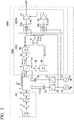
- Fig. 1 is a diagram showing a configuration example of an electric field sensor 100 according to the present embodiment.
- the electric field sensor 100 includes a light source 1, a lens 2, a polarizer 3, a ⁇ /4 wavelength plate 4, an electro-optic crystal 5, a polarization beam splitter 6 (light receiving means, light receiver), a lens 7a (light receiving means, light receiver), a lens 7b (light receiving means, light receiver), a light receiver 8a (light receiving means, light receiver), a light receiver 8b (light receiving means, light receiver), a differential amplifier 9 (light receiving means, light receiver), a filter 10 (first separator), a reference power supply 11 (reference electric field means, reference electric field applicator), a lock-in amplifier 12 (second separator), a gain controller 13, a variable gain amplifier 14, an electric field controller 15 (reference electric field means, reference electric field applicator), and a reference electric field source 16 (reference electric field means, reference electric field applicator).
- a filter 10 first separator
- a reference power supply 11 reference electric field means, reference electric field applicator
- lock-in amplifier 12 second separator
- a component 101 on an input side to the electro-optic crystal 5 includes the light source 1, the lens 2, the polarizer 3, and the ⁇ /4 wavelength plate 4.
- a component 102 (separation correction means, separation corrector) on an output side of the electro-optic crystal 5 includes the polarization beam splitter 6, the lens 7a, the lens 7b, the light receiver 8a, the light receiver 8b, the differential amplifier 9, the filter 10, the lock-in amplifier 12, the gain controller 13 (corrector), and the variable gain amplifier 14 (corrector).
- the component 102 on the output side of the electro-optic crystal 5 includes a light receiving means 1021 and a separation correction means 1022.
- the light receiving means 1021 includes the polarization beam splitter 6, the lens 7a, the lens 7b, the light receiver 8a, the light receiver 8b, and the differential amplifier 9.
- the separation correction means 1022 includes the filter 10, the lock-in amplifier 12, the gain controller 13, and the variable gain amplifier 14.
- the lens 2 is disposed between the light source 1 and the polarizer 3.
- the polarizer 3 is disposed between the lens 2 and the ⁇ /4 wavelength plate 4.
- the ⁇ /4 wavelength plate 4 is disposed between the polarizer 3 and the electro-optic crystal 5.
- the electro-optic crystal 5 is disposed between the ⁇ /4 wavelength plate 4 and the polarization beam splitter 6.
- the polarization beam splitter 6 is disposed between the electro-optic crystal 5 and the lens 7a, and between the electro-optic crystal 5 and the lens 7b.
- the lens 7a is disposed between the polarization beam splitter 6 and the light receiver 8a (light receiving element).
- the lens 7b is disposed between the polarization beam splitter 6 and the light receiver 8b (light receiving element).
- the light receiver 8a is disposed on an emission side of the lens 7a.
- the light receiver 8b is disposed on an emission side of the lens 7b.
- An output terminal of the light receiver 8a is connected to a first input terminal of the differential amplifier 9.
- An output terminal of the light receiver 8b is connected to a second input terminal of the differential amplifier 9.
- An output terminal of the differential amplifier 9 is connected to an input terminal of the filter 10 and a first input terminal of the lock-in amplifier 12.
- An output terminal of the filter 10 is connected to an input terminal of the variable gain amplifier 14.
- a second input terminal is connected to one end of the reference power supply 11 and an input terminal of the electric field controller 15, and an output terminal is connected to an input terminal of the gain controller 13.
- the other end of the reference power supply 11 is grounded.
- An output terminal of the gain controller 13 is connected to a control terminal of the variable gain amplifier 14.
- variable gain amplifier 14 An output terminal of the variable gain amplifier 14 is connected to an output of the electric field sensor 100.
- the other end of the electric field controller 15 is connected to the reference electric field source 16.
- the reference electric field source 16 In the electro-optic crystal 5, the reference electric field source 16 is provided on a first surface side, and a second surface side facing the first surface is grounded.
- the electric field sensor 100 measures an intensity of an electric field generated by a target.
- a measurement electric field source 23 is the target to be measured.
- the light source 1 is, for example, a laser diode (LD).
- LD laser diode
- the lens 2 is a collimator lens, which converts a light beam emitted by the light source into parallel light and emits it.
- the polarizer 3 polarizes the light beam emitted by the lens 2 into linear light.
- the ⁇ /4 wavelength plate 4 polarizes the light beam emitted by the polarizer 3 into circularly polarized light and emits it.
- the ⁇ /4 wavelength plate 4 is inserted in front of the electro-optic crystal 5 for polarization for the purpose of increasing a sensitivity near an origin of the electric field and for determining a polarity of the electric field.
- the ⁇ /4 wavelength plate 4 may not necessarily be mounted.
- a light beam emitted by the ⁇ /4 wavelength plate 4 is incident on the electro-optic crystal 5, and the electro-optic crystal 5 to which a reference electric field E(fref) is applied by the reference electric field source 16 is subjected to a measurement electric field E(meas) by the measurement electric field source 23 on the same surface as the surface to which the reference electric field E(fref) is applied.
- the electro-optic crystal 5 emits a light beam P (meas+fref) of circularly polarized light whose polarization state has changed due to a change in birefringence according to the reference electric field E(fref) and the measurement electric field E(meas).
- the electro-optic crystal 5 may be, for example, LiNbO 3 , LiTaO 3 , Bi 12 SiO 2 0 (BSO), Bi 12 GeO 20 (BGO), ADP, KDP, a crystal, or the like.
- the polarization beam splitter 6 separates the light beam of circularly polarized light emitted by the electro-optic crystal 5 into P-polarized light PH (meas+fref) and S-polarized light PS (meas+fref).
- the lens 7a is a collimator lens and focuses the light beam of the P-polarized light emitted by the polarization beam splitter 6 on the light receiver 8a.
- the lens 7b is a collimator lens and focuses the light beam of the S-polarized light emitted by the polarization beam splitter 6 on the light receiver 8b.
- the light receiver 8a photoelectrically converts an amount of received light and outputs it to the differential amplifier 9 as an electric signal VH (meas+fref) according to an electric field intensity.
- the light receiver 8b photoelectrically converts an amount of received light and outputs it to the differential amplifier 9 as an electric signal VS (meas+fref) according to an electric field intensity.
- the differential amplifier 9 amplifies a differential component of electric signals of the P polarized light component and the S polarized light component, and outputs an amplified electric signal V(meas+ref) to the input terminal of the filter 10 and the lock-in amplifier 12.
- the filter 10 outputs to the variable gain amplifier 14 an electric signal V(meas) from which a reference electric field signal component in a measurement signal output from the differential amplifier 9 is removed.
- the reference power supply 11 generates a reference signal fref for creating the reference electric field signal component and outputs the generated reference signal to the lock-in amplifier 12 and the electric field controller 15.
- the lock-in amplifier 12 extracts the reference electric field signal component V(fref) from the electric signal output from the differential amplifier 9 using the reference signal output from the reference power supply 11.
- the lock-in amplifier 12 may not necessarily be used, and a synchronous detection type amplifier may also be used.
- the gain controller 13 generates a control signal that controls an amplification factor according to the reference electric field signal component output from the lock-in amplifier 12, and outputs the generated control signal to the variable gain amplifier 14. For example, when a magnitude of a known reference electric field signal has decreased (sensitivity has decreased), the gain controller 13 outputs a control signal for increasing a gain of the variable gain amplifier 14 to the variable gain amplifier 14. As described above, the gain controller 13 functions as an automatic gain control (AGC; automatic gain control).
- AGC automatic gain control
- variable gain amplifier 14 varies an amplification factor of the signal output from the filter 10 according to the control signal output from the gain controller 13 and outputs the signal.
- the electric field controller 15 is a driver that drives the reference signal output from the reference power supply 11 to the electric field intensity, and outputs a drive signal to the reference electric field source 16.
- the reference electric field source 16 is a reference electric field source for monitoring a change in an electro-optic constant of the electro-optic crystal 5, is driven by the drive signal output from the electric field controller 15, and applies the reference electric field E(fref) to the electro-optic crystal 5. Applying the reference electric field E(fref) to the electro-optic crystal 5 as described above means that modulation is performed with the reference signal fref.
- the electric field sensor 100 obtains an amount of phase change induced by the electric field intensity applied to the electro-optic crystal 5 mounted in the sensor by an optical means.
- an optical action length of the electro-optic crystal 5 changes according to a thermal expansion coefficient of a material of the optical crystal. Since a phase change due to a change in a polarized wave state in the crystal caused by stress is added, it is necessary to provide an electric field sensor with high measurement stability by incorporating a mechanism for constantly monitoring the phase change and correcting the change.
- an amount of change in the linear electro-optic constant r eff can be monitored by applying the reference electric field signal E(fref) that generates a known electric field to the electro-optic crystal and detecting a change in the linear electro-optic constant r eff only with the reference signal component V(fref) in the subsequent stage at the lock-in amplifier 12.
- the signal of the reference signal component V(fref) is common from the light source to the input of the differential amplifier, when a sensitivity of the measurement signal is corrected by a calculator (the filter 10, the lock-in amplifier 12, the gain controller 13, the variable gain amplifier 14) according to an amount of variation, the electric field can be measured with high measurement stability even when the linear electro-optic constant r eff changes due to an ambient temperature or the like.
- a frequency of the reference signal component V(fref) and a measurement frequency band need to be separated so that an intensity of the reference signal does not affect the measurement signal. Therefore, in the present embodiment, the filter 10 is used to separate them so that an intensity of the reference signal does not affect the measurement signal.
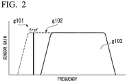
- Fig. 2 is a diagram for explaining effects of the electric field sensor 100 according to the present embodiment.
- the horizontal axis represents a frequency and the vertical axis represents a sensor gain of the electric field sensor 100.
- Reference sign g101 indicates a frequency fref of the reference signal
- reference sign g102 indicates frequency characteristics of the electric field sensor 100
- reference sign g103 indicates measurement frequency characteristics.
- the frequency fref is, for example, 10 Hz
- the measurement frequency is, for example, 100 Hz.
- the frequency of the reference signal component V(fref) need only be a frequency that does not affect the measurement frequency band, and may be a lower frequency or a higher frequency than the measurement frequency band as shown in Fig. 2 .
- a temperature variation or the like of each component in the electric field sensor 100 is corrected by applying the reference electric field to the electro-optic crystal 5, extracting the applied reference electric field, and performing AGC for the sensitivity of the signal to be measured using the gain controller 13.
- a reference electric field having a known magnitude of the electric field is applied to the electro-optic crystal 5 during the measurement.
- an influence of the temperature dependence is corrected by taking a difference from the reference electric field with a magnitude of the known reference electric field as a reference without a change in magnitude of the electric field due to a temperature.
- the measurement electric field signal E(meas) and the reference electric field signal E(fref) for monitoring an amount of change in the linear electro-optic constant r eff are applied to the same electro-optic crystal, and a light beam that probes a phase change of the electro-optic crystal is also the same.
- a measurement electric field signal component fm and a reference electric field signal fref are superimposed on a horizontal polarization component signal and a vertical polarization component signal in the polarization beam splitter 6.
- a difference in sensitivity between the two light receivers (8a and 8b) and a change in a polarization separation ratio of the polarization beam splitter 6 can also be removed by the differential amplifier 9 and the calculator (the filter 10, the lock-in amplifier 12, the gain controller 13, the variable gain amplifier 14) in the subsequent stage.
- the reference signal is extracted by the lock-in amplifier 12, and a signal corresponding to a required gain is generated by the gain controller 13.
- the gain of the variable gain amplifier 14 is actively adjusted to a gain that corrects a variation of the electro-optic constant r eff , and thereby highly stable electric field measurement can be realized even with respect to a variation such as temperature.
- Fig. 3 is a diagram showing a configuration example of an electric field sensor 100A according to the present embodiment.
- the electric field sensor 100A includes a light source 1, a lens 2, a polarizer 3, a ⁇ /4 wavelength plate 4, an electro-optic crystal 5, a polarization beam splitter 6, a lens 7a, a lens 7b, a light receiver 8a, a light receiver 8b, a differential amplifier 9, a reference power supply 11 (reference electric field means, reference electric field applicator), a lock-in amplifier 12a (first separator), a lock-in amplifier 12b (second separator), a gain controller 13, a variable gain amplifier 14, an electric field controller 15 (reference electric field means, reference electric field applicator), a reference electric field source 16 (reference electric field means, reference electric field applicator), a measurement power supply 21 (measurement electric field means, measurement electric field applicator), and a measurement electric field controller 22 (measurement electric field means, measurement electric field applicator).
- a reference power supply 11 reference electric field means, reference electric field applicator
- a lock-in amplifier 12a first separator
- a component 101 on an input side to the electro-optic crystal 5 includes the light source 1, the lens 2, the polarizer 3, and the ⁇ /4 wavelength plate 4.
- a component 102A (separation correction means, separation corrector) on an output side of the electro-optic crystal 5 includes the polarization beam splitter 6, the lens 7a, the lens 7b, the light receiver 8a, the light receiver 8b, the differential amplifier 9, the lock-in amplifier 12a, the lock-in amplifier 12b, the gain controller 13, and the variable gain amplifier 14.
- the component 102 on the output side of the electro-optic crystal 5 includes a light receiving means 1021 and a separation correction means 1022A.
- the light receiving means 1021 includes the polarization beam splitter 6, the lens 7a, the lens 7b, the light receiver 8a, the light receiver 8b, and the differential amplifier 9.
- the separation correction means 1022A includes the lock-in amplifier 12a (first amplifier), the lock-in amplifier 12b (second amplifier), the gain controller 13, and the variable gain amplifier 14.
- a disposition of optical components of the electric field sensor 100A is the same as that of the electric field sensor 100.
- An output terminal of the light receiver 8a is connected to a first input terminal of the differential amplifier 9.
- An output terminal of the light receiver 8b is connected to a second input terminal of the differential amplifier 9.
- An output terminal of the differential amplifier 9 is connected to a first input terminal of the lock-in amplifier 12a and a first input terminal of the lock-in amplifier 12b.
- a second input terminal is connected to one end of the measurement power supply 21 and an input terminal of the measurement electric field controller 22, and an output terminal is connected to an input terminal of the variable gain amplifier 14.
- a second input terminal is connected to one end of the reference power supply 11 and an input terminal of the electric field controller 15, and an output terminal is connected to an input terminal of the gain controller 13.
- the other end of the reference power supply 11 is grounded.
- An output terminal of the gain controller 13 is connected to a control terminal of the variable gain amplifier 14.
- An output terminal of the variable gain amplifier 14 is connected to an output of the electric field sensor 100A.
- the other terminal of the electric field controller 15 is connected to the reference electric field source 16.
- the reference electric field source 16 and a measurement electric field source 23 are provided on a first surface side, and a second surface side facing the first surface is grounded.
- the other end of the measurement power supply 21 is grounded.
- the other terminal of the measurement electric field controller 22 is connected to the measurement electric field source 23.
- the electric field sensor 100A measures an intensity of an electric field generated by a target.
- the measurement electric field source 23 is the target to be measured.
- the measurement power supply 21 generates a measurement referential signal fm.
- the measurement electric field controller 22 is a driver that drives the measurement referential signal output from the measurement power supply 21 to an electric field intensity, and outputs a drive signal to the measurement electric field source 23.
- the measurement electric field source 23 is driven by the drive signal output from the measurement electric field controller 22 and applies a measurement electric field E(fm) to the electro-optic crystal 5. Applying the reference electric field measurement electric field E(fm) to the electro-optic crystal 5 as described above means that the measurement electric field is modulated with the frequency fm.
- the differential amplifier 9 amplifies a differential component of electric signals of a P polarized light component and an S polarized light component, and outputs an amplified electric signal V(fm+fref) to the lock-in amplifier 12a and the lock-in amplifier 12b.
- the lock-in amplifier 12a extracts a measurement electric field signal component V(fm) from the electric signal output from the differential amplifier 9 using a measurement signal output from the measurement power supply 21.
- the lock-in amplifier 12b extracts a reference electric field signal component V(fref) from the electric signal output from the differential amplifier 9 using a reference signal output from the reference power supply 11.
- a referential signal E(fm) is superimposed on the measurement electric field in the present embodiment. Then, also in the present embodiment, only the measurement signal component is detected in the component 102A on the output side of the electro-optic crystal 5. Also in the present embodiment, a level of the measurement signal is corrected by the gain controller 13 and the variable gain amplifier 14 on the basis of a magnitude of the reference signal detected by the lock-in amplifier 12b.
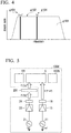
- Fig. 4 is a diagram for explaining effects of the electric field sensor 100A according to the present embodiment.
- the horizontal axis represents a frequency and the vertical axis represents a sensor gain of the electric field sensor 100A.
- Reference sign g101 indicates a frequency fref of the reference signal
- reference sign g102 indicates frequency characteristics of the electric field sensor 100A
- reference sign g103 indicates measurement frequency characteristics.
- Reference sign g104 indicates a reference frequency for measurement. As shown in Fig. 4 , the frequency fref of the reference signal is different from the reference frequency for measurement.
- the electric field sensor 100A of the present embodiment can obtain the same effects as those of the electric field sensor 100 of the first embodiment. Further, according to the present embodiment, when there is capacitive coupling noise from the power supply or noise due to electromagnetic induction or the like, these noise components can be removed. Therefore, according to the present embodiment, a signal-to-noise ratio (SN ratio) can be further improved as compared with that in the first embodiment.
- SN ratio signal-to-noise ratio
- Fig. 5 is a diagram showing a configuration example when the electric field sensor 100A of the second embodiment is applied to measurement of a generated electric field distribution of a solar cell.
- the electric field sensor 100A includes the component 101 on an input side to the electro-optic crystal 5 ( Fig. 3 ), the component 102A on an output side of the electro-optic crystal 5 ( Fig. 3 ), the reference power supply 11, the electric field controller 15, the reference electric field source 16, the measurement electric field controller 22 (measurement electric field means, measurement electric field applicator), the measurement power supply 21 (measurement electric field means, measurement electric field applicator), and a solar cell irradiation light source 24 (measurement electric field means, measurement electric field applicator).
- a solar cell 201 is a target to be measured.
- An electric field sensor 100A' measures an intensity of an electric field generated by the solar cell 201 which is a target.
- a connection of the electric field sensor 100A' that is different from the connection of the electric field sensor 100A will be described.
- the other terminal of the measurement electric field controller 22 is connected to the solar cell irradiation light source 24.
- the measurement power supply 21 generates the measurement referential signal fm.
- the measurement electric field controller 22 is a driver that drives the measurement referential signal output from the measurement power supply 21 to an electric field intensity and outputs a drive signal to the solar cell irradiation light source 24.
- the solar cell irradiation light source 24 is a light source for causing the solar cell 201 to generate electricity.
- the solar cell irradiation light source 24 is driven by the drive signal output from the measurement electric field controller 22, and irradiates the solar cell 201 with a light beam P(fm) modulated by the measurement referential signal fm.
- the solar cell 201 is irradiated with light for power generation modulated by the measurement referential signal at a frequency fm.
- the solar cell 201 generates an electric field E(fm) using the irradiated light.
- the electric field sensor 100A' provides the electric field E(fm) generated by the solar cell 201 to the electro-optic crystal 5. Then, a reference electric field E(ref) modulated by the reference signal at the frequency fref is applied to the electro-optic crystal 5.
- the electric field E(fm) generated by the solar cell 201 instead of the measurement electric field source 23 in the electric field sensor 100A of Fig. 3 is applied to the electro-optic crystal 5.
- the electric field sensor 100A' measures the electric field E(fm) generated by the solar cell 201.
- Fig. 6 is a diagram showing a configuration example when the electric field sensor 100 of the first embodiment is applied to the electric field sensor of a waveguide type.
- an electric field sensor 100C includes a light source 301, an optical fiber 302, an electro-optic crystal 303, a reference power supply 305, an optical fiber 306, a light receiver 307, and a separation correction means 308.
- the electro-optic crystal 303 includes a first optical waveguide 3031, an electrode 3032 (third electrode), an electrode 3033 (first electrode), an electrode 3034 (second electrode), and a second optical waveguide 3035.
- One end of the optical fiber 302 is connected to the light source 301.
- the other end of the optical fiber 302 is connected to an input terminal of the first optical waveguide 3031 of the electro-optic crystal 303.
- the optical fiber 302 is connected to the first optical waveguide 3031 of the electro-optic crystal 303 via a photocoupler.
- the first optical waveguide 3031 is formed in a Y shape and includes one input terminal and two output terminals (a first output terminal and a second output terminal). In the first optical waveguide 3031, the first output terminal is connected to an input terminal of the electrode 3032, and the second output terminal is connected to an input terminal of the electrode 3033.
- a connection part to the outside is grounded, and an output terminal is connected to a first input terminal of the second optical waveguide 3035.
- a connection part to the outside is connected to a measurement electric field source 304, and an output terminal is connected to an input terminal of the electrode 3034.
- a connection part to the outside is connected to one end of the reference power supply 305, and an output terminal is connected to a second input terminal of the second optical waveguide 3035.
- the second optical waveguide 3035 is formed in a Y shape and includes two input terminals (a first output terminal and a second output terminal) and one output terminal.
- the output terminal of the second optical waveguide 3035 is connected to an input end of the optical fiber 306.
- the other end of the optical fiber 306 is connected to the light receiver 307.
- the optical fiber 306 is connected to the second optical waveguide 3035 of the electro-optic crystal 303.
- a light beam incident on the optical fiber 302 from the light source 301 is a light beam of linearly polarized light.
- the measurement electric field source 304 applies a measurement electric field E(meas) to the electrode 3033 to apply the measurement electric field E(meas) to the electro-optic crystal 303.
- the reference power supply 305 generates a reference signal fref for creating a reference electric field signal component and applies it to the electrode 3034 to apply the reference signal fref to the electro-optic crystal 303.
- a configuration emitted from the electro-optic crystal 303 to the optical fiber 306 is also linearly polarized light.
- the light receiver 307 receives the light emitted from the electro-optic crystal 303 via the optical fiber 306 and converts the received light into an electric signal.
- the electric field sensor 100C measures an intensity of an electric field generated by a target.
- the measurement electric field source 304 is the target to be measured.
- the separation correction means 308 detects a measurement signal and a reference signal from the electric signal output from the light receiver 307.
- the separation correction means 308 corrects a signal level of the measurement signal on the basis of a signal level of the detected reference signal.
- the separation correction means 308 may be constituted by, for example, the filter 10 (first separator), the lock-in amplifier 12 (second separator), the gain controller 13, and the variable gain amplifier 14 as in Fig. 1 .
- the separation correction means 308 may be a central processing unit (CPU), and may also be one in which outputs of the measurement signal component and the reference signal component are A/D-converted into numerical values, and then calculated and processed by software.
- the second example is one in which the barrack-type electro-optic crystal of Fig. 1 is configured in the electric field sensor of an optical waveguide-type.
- the light source 301 corresponds to the light source 1 ( Fig. 1 )
- the measurement electric field source 304 corresponds to the measurement electric field source 23
- the reference power supply 305 corresponds to the reference power supply 11.
- a signal component passing through the electrode 3032 is not affected by the electric field.
- a phase of a signal component passing through the electrode 3033 and the electrode 3034 changes due to a change in the measurement electric field E(meas).
- the second optical waveguide 3035 mixes the signal component passing through the electrode 3032 with the signal component passing through the electrode 3033 and the electrode 3034.
- the light receiver 307 receives such a signal and obtains a phase change from the received signal on the basis of the reference signal.
- a gain of the extracted signal is controlled by the gain controller 13 ( Fig. 1 ) as in the electric field sensor 100 ( Fig.
- the electric field sensor 100C converts the signal received by the light receiver 307 into an electric signal and extracts the measurement signal component V(meas) from the converted electric signal using the filter 10 ( Fig. 1 ). Then, in the electric field sensor 100C, the reference signal V(fref) is detected by the lock-in amplifier 12 ( Fig. 1 ), and the variable gain amplifier 14 ( Fig. 1 ) is controlled by the gain controller 13 ( Fig. 1 ) using the detected reference signal V(fref).
- a phase change of the electro-optic crystal 303 is temperature dependent.
- components the reference power supply 305 and the electrode 3034
- the light receiver 307 monitors a phase change with respect to a temperature change, and an arithmetic device (not shown) corrects an intensity of the measurement signal according to a variation amount, and thereby electric field can be measured with high measurement stability even when an ambient temperature or the like changes.
- Non-Patent Literature 4 As for a configuration example and an operation example of the vertical electric field sensor, see, for example, Non-Patent Literature 4.
- Fig. 7 is a diagram showing a configuration example in which the electric field sensor of the present embodiment is applied to the vertical electric field sensor.
- Fig. 7 is an example in which the electric field sensor of the first embodiment is applied to the vertical electric field sensor.
- the electric field sensor of the second embodiment can also be used as a vertical electric field sensor as a matter of course.
- an electric field sensor 100D includes the light source 1, a beam splitter 401, a ⁇ /4 wavelength plate 402, an electro-optic crystal 5D, the polarization beam splitter 6, the lens 7a, the lens 7b, the light receiver 8a, the light receiver 8b, the differential amplifier 9, the filter 10 (first separator), the reference power supply 11 (reference electric field means, reference electric field applicator), the lock-in amplifier 12 (second separator), the gain controller 13, the variable gain amplifier 14, the electric field controller 15 (reference electric field means, reference electric field applicator), and the reference electric field source 16 (reference electric field means, reference electric field applicator).
- a component 101D on an input side to the electro-optic crystal 5D includes the light source 1, the beam splitter 401, and the ⁇ /4 wavelength plate 402.
- the component 102 (separation correction means, separation corrector) on an output side from the electro-optic crystal 5D includes the polarization beam splitter 6, the lens 7a, the lens 7b, the light receiver 8a, the light receiver 8b, the differential amplifier 9, the filter 10, the lock-in amplifier 12, the gain controller 13, and the variable gain amplifier 14.
- the component 102 on the output side of the electro-optic crystal 5D includes the light receiving means 1021 and the separation correction means 1022.
- an indium tin oxide (ITO) electrode 5D1 is grounded.
- the ITO electrode 5D1 is a transparent electrode.
- the electro-optic crystal 5D includes a mirror 5D2 provided on a second surface facing a first surface on which the ITO electrode 5D1 is disposed.
- the electro-optic crystal 5 emits the light beam P (meas+fref) of circularly polarized light whose polarization state has changed due to a change in birefringence according to the reference electric field E(fref) and the measurement electric field E(meas).
- the electro-optic crystal 5D is, for example, LiNbO 3 , LiTaO 3 , Bi 12 SiO 2 O (BSO), Bi 12 GeO 20 (BGO), ADP, KDP, a crystal, or the like.
- a disposition of the components of the electric field sensor 100D different from the disposition of the electric field sensor 100 will be described.
- the beam splitter 401 is disposed between the light source 1 and the ⁇ /4 wavelength plate 402.
- the ⁇ /4 wavelength plate 402 is disposed between the beam splitter 401 and the electro-optic crystal 5.
- the surface having the grounded ITO electrode 5D1 is disposed on a side facing the ⁇ /4 wavelength plate 402, and the surface having the mirror 5D2 is disposed on a side facing the reference electric field source 16 and the measurement electric field source 23.
- the electric field sensor 100D measures an intensity of an electric field generated by a target.
- the measurement electric field source 23 is the target to be measured.
- the beam splitter 401 divides a light beam emitted by the light source 1 into two, emits one light beam to the polarization beam splitter 6, and emits the other light beam to the ⁇ /4 wavelength plate 402.
- the light beam that has been emitted to the ⁇ /4 wavelength plate 402 is reflected by the mirror 5D2 of the electro-optic crystal 5D, passes through the ⁇ /4 wavelength plate 402, and is incident on the beam splitter 401.
- the light beam emitted to the polarization beam splitter 6 by the beam splitter 401 also includes the light beam of the light source 1 that has passed through the ⁇ /4 wavelength plate 402, has passed through the electro-optic crystal 5D, has been reflected by the mirror 5D2, and has passed through the ⁇ /4 wavelength plate 402 in addition to the light beam that has been divided from the light source 1.
- the ⁇ /4 wavelength plate 402 gives a phase difference of ⁇ /4 to a wavelength of the light beam incident from the beam splitter 401 and causes a phase difference of ⁇ /4 in a wavelength of the light beam that has passed through the electro-optic crystal 5D and has been reflected by the mirror 5D2.
- a phase change occurs with respect to an electric field (reference electric field, measurement electric field) applied to the ITO electrode 5D1 and a lower surface of the electro-optic crystal 5D.
- the electric field sensor 100D measures an electric field intensity by acquiring a phase change of light when the light beam is reflected by the mirror 5D2 and returned through the ITO electrode 5D1.
- the configuration may also be based on the configuration of the electric field sensor 100A shown in Fig. 3 .
- the measurement referential signal may be supplied to the measurement electric field source 23 ( Fig. 3 ) via the measurement electric field controller 22 ( Fig. 3 ).
- a configuration of the separation correction means 1022 is the same as that of the separation correction means 1022A ( Fig. 3 ).
Landscapes
- Physics & Mathematics (AREA)
- General Physics & Mathematics (AREA)
- Nonlinear Science (AREA)
- Optics & Photonics (AREA)
- Electromagnetism (AREA)
- Chemical & Material Sciences (AREA)
- Engineering & Computer Science (AREA)
- Ceramic Engineering (AREA)
- Crystallography & Structural Chemistry (AREA)
- Measuring Instrument Details And Bridges, And Automatic Balancing Devices (AREA)
- Optical Modulation, Optical Deflection, Nonlinear Optics, Optical Demodulation, Optical Logic Elements (AREA)
Abstract
Description
- The present invention relates to an electric field sensor.
- Priority is claimed on
Japanese Patent Application No. 2018-180875 - As an electric field sensor for measuring an electric field, a sensor element made of a metal such as a general dipole antenna is generally used.
- On the other hand, in electric field measurement using an electro-optic effect, since a sensor element is not made of a metal, an electric field to be measured can be measured without being disturbed, and furthermore, measurement with a high spatial resolution can be performed. Therefore, electric field measurement using the electro-optic effect has begun to be used in various applications. The "electro-optic effect" is an effect in which, when an electric field is applied to an electro-optic crystal, a refractive index of light passing through the electro-optic crystal changes in proportion to an electric field intensity. A change in the refractive index causes a phase change in a light wave passing through the optical crystal. In electric field measurement using the electro-optic effect, an electric field applied to an electro-optic crystal can be measured by measuring a change in phase (see, for example,
Patent Literatures 1 and 2). - An outline of a configuration and an operation of a conventional electric field sensor using the electro-optic effect will be described.
-
Fig. 8 is a diagram showing a configuration example of a conventional electric field sensor utilizing an electro-optic effect. As shown inFig. 8 , anelectric field sensor 900 includes alight source 901, apolarizer 902, awavelength plate 903, an electro-optic crystal 904, apolarizer 905, and alight receiver 906. - The
light source 901 is, for example, a semiconductor laser. Thepolarizer 902 emits linearly polarized light (reference sign 911) among light beams incident from thelight source 901. Thewavelength plate 903 is a λ/4 wavelength plate and polarizes the light beams incident from thepolarizer 902 into circularly polarized light (reference sign 912) to emit it. The electro-optic crystal 904 changes a polarization state due to a change in birefringence according to an electric field intensity applied by an external electric field source. The electro-optic crystal 904 emits a light beam of elliptically polarized light (reference sign 913) whose polarization state has changed. Thepolarizer 905 converts the light beam emitted by the electro-optic crystal 904 into linearly polarized light. Thelight receiver 906 converts the light beam emitted by thepolarizer 905 into an electric signal and outputs it. The reason why thewavelength plate 903 is used is to prevent a detection sensitivity of the same birefringent component as a polarization axis of the light source from decreasing when linearly polarized light is incident on the electro-optic crystal 904, and because it is necessary to use circularly polarized light to determine a polarity of the electric field. In the configuration ofFig. 8 , an electric field intensity to be measured is converted into an electric intensity by converting a change in light intensity into a light receiver electric signal (see, for example, Non-Patent Literature 1). - In the configuration of
Fig. 8 , a measured value may vary due to a change in an amount of light from the light source. A configuration example in which a polarization beam splitter is disposed instead of the polarizer after an output of the electro-optic crystal to reduce the variation will be described.Fig. 9 is a diagram showing a configuration example in which a polarization beam splitter is disposed instead of an analyzer (the polarizer 905) after an output of the electro-optic crystal 904. As shown inFig. 9 , anelectric field sensor 900A includes alight source 901, apolarizer 902, awavelength plate 903, an electro-optic crystal 904, abeam splitter 907, amirror 908, afirst light receiver 906a, a secondlight receiver 906b, and adifferential amplifier 909. - The
beam splitter 907 is a polarization beam splitter and separates incident light into a horizontal polarization component PP and a vertical polarization component Ps. For example, thefirst light receiver 906a converts the horizontal polarization component PP into an electric signal. Thesecond light receiver 906b converts the vertical polarization component PS that has been totally reflected by the mirror into an electric signal. Thedifferential amplifier 909 performs differential output of the two component signals output from the firstlight receiver 906a and the secondlight receiver 906b. With this configuration, common variation components such as light source variation are removed (see, for example, Non-Patent Literature 2). - Next, a refractive index change, an optical phase change, incident optical power, and emitted optical power of the electro-
optic crystal 904 will be described. - When an external electric field E is applied to the electro-
optic crystal 904, a magnitude Δn of change in a refractive index of the electro-optic crystal 904 is represented by the following expression (1).
[Math. 1]
- In expression (1), Δn is a refractive index change, n is an unperturbed refractive index, E is an electric field intensity, and reff is a linear electro-optic coefficient.
- An optical phase change ΔΦ at this time is represented by the following expression (2).
[Math. 2]
- In expression (2), ΔΦ is a phase change, L is a crystal length, d is a crystal thickness, and λ is a wavelength.
- When the
wavelength plate 903 gives a phase difference of π/2 to light linearly polarized by thepolarizer 902 to convert it into circularly polarized light, an optical power intensity Pout output from the analyzer (polarizer 905) is represented by the following expression (3).
[Math. 3]
In expression (3), Pout is the optical power intensity output from the analyzer (polarizer 905), and Pin is optical power input to the electro-optic crystal. -
- [Patent Literature 1]
Japanese Unexamined Patent Application, First Publication No. 2002-122622 - [Patent Literature 2]
Japanese Unexamined Patent Application, First Publication No. 2007-101384 -
- [Non-Patent Literature 1]
Tokio Kihara, "Measurements of Voltage by Using an Electro-Optic Crystal Sensor", Fukui University of Technology, Memoirs of Fukui University of Technology No. 17, p37-p45, 1987 - [Non-Patent Literature 2]
Xiaojun Zeng, Haiqing Chen, "Electro-optical measurement of highly intense electric field with high frequency," Optical Sensing, Imaging and Manipulation for Biological and Biomedical Applications Held in Taipei, Taiwan on 26-27 July 2000, p298 -307 - [Non-Patent Literature 3]
Hiroshi Ito, Tadashi Ichikawa, "Development of Electric Field Meter Using Ti:LiNbO3 Integrated Optics," R&D Review of Toyota Central R&D Labs, R&D Review Editorial Committee, Vol. 29 No. 3, 1994.09, p13-24 - [Non-Patent Literature 4]
Hajime Kuzumi, Masayuki Yoshima, Eiji Konishi, "Technology for Testing Printed Wiring Boards Using E-O Effect," SMH Journal, Vol. 12, (1996) No. 3, p. 28-32 - A magnitude of an amount of phase change with respect to an electric field of an optical crystal, that is, a linear electro-optic constant reff corresponding to a sensitivity, changes according to a temperature dependence of birefringence of the optical crystal. Further, a phase change is added to the linear electro-optic constant reff due to a change in a polarized wave state in the crystal caused by stress such as extension and contraction of an electro-optical action length of the crystal due to a thermal expansion coefficient of a material of the optical crystal, and thereby a sensor output varies due to factors other than an electric field to be measured, and the variation amount is added to an original measurement output, resulting in a decrease in measurement stability.
- It is known that natural birefringence of an optical crystal changes due to a temperature variation. For example, when a wavelength of a light source changes due to a temperature, an amount of phase shift due to a λ/4 wavelength plate is changed. Since an optical crystal has an in-plane distribution of an electro-optic constant and a position of a light beam passing through the crystal shifts due to a change in ambient temperature, a change in sensitivity with respect to an electric field intensity is also a variation factor of a sensitivity to the electric field intensity. Since light entering an electro-optic crystal changes from circularly polarized light to elliptically polarized light due to a temperature dependence of components used for guiding light into a sensor such as a λ/4 wavelength plate or polarization-maintaining fibers, a decrease in detection sensitivity is also a variation factor of the sensitivity to the electric field intensity. Further, since a polarization beam splitter also has temperature dependence, a ratio between a P-wave component and an S-wave component that are separated changes.
- Due to these variation factors, even when branching is performed at a polarization beam splitter to configure a differential optical system so that a temporal variation in intensity of a light source is cancelled as in the technology described in Non-Patent Literature 2, it is not easy to cancel the temperature-dependent factors of the entire sensor and perform highly stable electric field measurement.
- One aspect of the present invention provides an electric field sensor that utilizes an electro-optic effect and can measure an electric field intensity without impairing measurement stability even when an ambient temperature or the like changes.
- An electric field sensor (100, 100A, 100A', 100C, 100D) according to one aspect of the present invention is an electric field sensor which measures an electric field generated by a target utilizing an electro-optic effect and includes a light source (1), an electro-optic crystal (5, 5D) on which light in a predetermined polarization state emitted from the light source is incident and which is subjected to an electric field generated by the target, a reference electric field applicator (
reference power supply 11,electric field controller 15, reference electric field source 16) configured to apply an electric field based on a reference signal with a known signal level to the electro-optic crystal, a light receiver (1021) configured to receive light emitted from the electro-optic crystal and to convert the received light into an electric signal, and a separation corrector (1022, 1022A) configured to separate the electric signal into a measurement signal based on the electric field generated by the target and the reference signal and to correct a signal level of the measurement signal on the basis of the signal level of the separated reference signal. - With the configuration described above, the electric field sensor can monitor an amount of change in a linear electro-optic constant reff by applying an electric field based on the reference signal with a known signal level to the electro-optic crystal and detecting a change in the linear electro-optic constant reff only with the reference signal at a second separator. When a signal level of the measurement signal is corrected on the basis of the signal level of the reference signal detected as described above, the electric field sensor utilizes an electro-optic effect and can measure the electric field intensity without impairing measurement stability even when an ambient temperature or the like changes.
- In the electric field sensor according to one aspect of the present invention, the separation corrector may include a first separator (a filter 10) configured to separate the measurement signal from the electric signal, a second separator (a lock-in amplifier 12) configured to separate the reference signal from the electric signal, and a corrector (a
gain controller 13, a variable gain amplifier 14) configured to correct the signal level of the measurement signal on the basis of the signal level of the separated reference signal. - With the configuration described above, the electric field sensor can obtain the amount of phase change induced by the electric field intensity applied to the electro-optic crystal. With the configuration described above, it is possible to provide an electric field sensor with high measurement stability by correcting a phase change using the separation corrector that constantly monitors the phase change.
- The electric field sensor according to one aspect of the present invention may further include a measurement electric field applicator (
measurement power supply 21, measurement electric field controller 22) configured to apply a referential signal with a known signal level to the target, and the separation corrector may include a first separator (lock-inamplifier 12a) configured to separate the measurement signal on which the referential signal is superimposed from the electric signal, a second separator (lock-inamplifier 12b) configured to separate the reference signal from the electric signal, and a corrector (gaincontroller 13, variable gain amplifier 14) configured to correct the signal level of the measurement signal on the basis of the signal level of the separated reference signal. - With the configuration described above, the electric field sensor is configured such that the referential signal is superimposed on the measurement signal by applying the electric field based on the referential signal to the electric field generated by the target, and the first separator separates the measurement signal on which the referential signal is superimposed from the electric signal. Thereby, for example, when there is capacitive coupling noise from the power supply or noise due to electromagnetic induction or the like in the surroundings in addition to the electric field to be measured, the electric field sensor can remove these noise components with the above-described configuration. As a result, the electric field sensor can measure the electric field intensity with high accuracy even when an electric field intensity to be measured is small and a signal to noise (SN) ratio is poor.
- In the electric field sensor according to one aspect of the present invention, the target may be a solar cell (201), the light source (solar cell irradiation light source 24) may be configured to irradiate the solar cell with light, and the electro-optic crystal may be subjected to an electric field generated by the solar cell irradiated with the light from the light source as an electric field generated by the target.
- With the configuration described above, the electric field sensor can measure the electric field generated by irradiating the solar cell with light. Thereby, with the configuration described above, since an electric field sensitivity of the electric field sensor can be corrected using the reference signal even when an ambient temperature changes, highly stable measurement is possible.
- In the electric field sensor according to one aspect of the present invention, the electro-optic crystal may include a first optical waveguide (3031) on which light of the light source is incident, a first electrode (3033) which is connected to a first output of the first optical waveguide and to which the electric field generated by the target is input, a second electrode (3034) which is connected to the first electrode and to which the electric field based on the reference signal is applied, a third electrode (3032) connected to a first output of the first optical waveguide and grounded, and a second optical waveguide (3035) having a first input to which the second electrode is connected, a second input to which the third electrode is connected, and an output connected to the light receiver.
- With the configuration described above, the electric field sensor can monitor a phase change with respect to a temperature change by applying the electric field based on the reference signal even in the electric field sensor of an optical waveguide-type. With the configuration described above, it is possible to provide an electric field sensor with high measurement stability by correcting a phase change using the separation corrector that constantly monitors the phase change.
- The electric field sensor according to one aspect of the present invention may further include a transparent electrode (ITO electrode 5D1) disposed on a first surface of the electro-optic crystal (5D), and a mirror (5D2) disposed on a second surface of the electro-optic crystal facing the first surface, light emitted from the light source may be incident from the transparent electrode, the light incident from the transparent electrode may be reflected by the mirror, and the reflected light may be emitted from the transparent electrode.
- With the configuration described above, the electric field sensor measures an electric field intensity by acquiring a phase change of light when a light beam is reflected by the mirror and returned through the transparent electrode. With the configuration described above, the electric field sensor can monitor a phase change with respect to a temperature change by applying the electric field based on the reference even when a phase change occurs with respect to the electric field applied to the transparent electrode and a lower surface of the crystal. With the configuration described above, it is possible to provide an electric field sensor with high measurement stability by correcting a phase change using the separation corrector that constantly monitors the phase change.
- In the electric field sensor according to one aspect of the present invention, the predetermined polarization state may be circularly polarized light.
- With the configuration described above, the electric field sensor can determine a polarity of the electric field using the circularly polarized light.
- In the electric field sensor according to one aspect of the present invention, a frequency of the reference signal may be in a frequency band that does not affect the measurement signal.
- With the configuration described above, since the electric field sensor is configured such that the reference signal intensity does not affect the measurement signal, it is possible to provide an electric field sensor with high measurement stability.
- In the electric field sensor according to one aspect of the present invention, the light receiver may include a polarization beam splitter configured to separate circularly polarized light emitted from the electro-optic crystal into P-polarized light and S-polarized light, and a differential amplifier configured to amplify a differential component of electric signals of the P-polarized light and the S-polarized light separated by the polarization beam splitter and to output the amplified electric signal to the separation corrector.
- With the configuration described above, when a signal level of the measurement signal is corrected on the basis of the signal level of the reference signal detected as described above, the electric field sensor utilizes an electro-optic effect and can measure the electric field intensity without impairing measurement stability even when an ambient temperature or the like changes.
- In the electric field sensor according to one aspect of the present invention, the separation corrector may include a filter configured to remove a signal component of the electric field based on the reference signal in the electric signal output from the differential amplifier, an amplifier configured to extract a signal component of the electric field based on the reference signal in the electric signal output from the differential amplifier using the reference signal, a gain controller configured to generate a control signal that controls an amplification factor according to the signal component of the electric field based on the reference signal output from the amplifier, and a variable gain amplifier configured to vary an amplification factor of the electric signal output from the filter in which the signal component of the electric field based on the reference signal is removed according to the control signal output from the gain controller, and to output the electric signal.
- With the configuration described above, when a signal level of the measurement signal is corrected on the basis of the signal level of the reference signal detected as described above, the electric field sensor utilizes an electro-optic effect and can measure the electric field intensity without impairing measurement stability even when an ambient temperature or the like changes.
- The electric field sensor according to one aspect of the present invention may further include a measurement electric field applicator configured to apply a referential signal with a known signal level to the target, and the light receiver may include a polarization beam splitter configured to separate circularly polarized light emitted from the electro-optic crystal into P-polarized light and S-polarized light, and a differential amplifier configured to amplify a differential component of electric signals of the P-polarized light and the S-polarized light separated by the polarization beam splitter and to output the amplified electric signal to the separation corrector.
- With the configuration described above, when there is capacitive coupling noise from the power supply or noise due to electromagnetic induction or the like in the surroundings in addition to the electric field to be measured, the electric field sensor can remove these noise components with the above-described configuration. As a result, the electric field sensor can measure the electric field intensity with high accuracy even when an electric field intensity to be measured is small and the SN ratio is poor.
- In the electric field sensor according to one aspect of the present invention, the separation corrector may include a first amplifier configured to extract a signal component of an electric field based on the measurement signal in an electric signal output from the differential amplifier using the measurement signal, a second amplifier configured to extract a signal component of an electric field based on the reference signal in an electric signal output from the differential amplifier using the reference signal, a gain controller configured to generate a control signal that controls an amplification factor according to a signal component of the electric field based on the reference signal output from the second amplifier, and a variable gain amplifier configured to vary an amplification factor of the electric signal of the signal component of the electric field based on the measurement signal output from the first amplifier according to the control signal output from the gain controller, and to output the electric signal.
- With the configuration described above, when there is capacitive coupling noise from the power supply or noise due to electromagnetic induction or the like in the surroundings in addition to the electric field to be measured, the electric field sensor can remove these noise components with the above-described configuration. As a result, the electric field sensor can measure the electric field intensity with high accuracy even when an electric field intensity to be measured is small and the SN ratio is poor.
- In the electric field sensor according to one aspect of the present invention, the separation corrector may be configured to measure the electric field generated by the target by acquiring a phase change of light that has been emitted by the light source, reflected by the mirror, and returned through the transparent electrode.
- With the configuration described above, the electric field sensor can monitor a phase change with respect to a temperature change by applying the electric field based on the reference even when a phase change occurs with respect to the electric field applied to the transparent electrode and a lower surface of the crystal.
- In the electric field sensor according to one aspect of the present invention, the light receiver may include a polarization beam splitter configured to separate circularly polarized light emitted from the electro-optic crystal into P-polarized light and S-polarized light, and a differential amplifier configured to amplify a differential component of electric signals of the P-polarized light and the S-polarized light separated by the polarization beam splitter and to output the amplified electric signal to the separation corrector.
- With the configuration described above, it is possible to provide an electric field sensor with high measurement stability by correcting a phase change using the separation corrector that constantly monitors the phase change.
- In the electric field sensor according to one aspect of the present invention, the separation corrector may include a filter configured to remove a signal component of the electric field based on the reference signal in the electric signal output from the differential amplifier, an amplifier configured to extract a signal component of the electric field based on the reference signal in the electric signal output from the differential amplifier using the reference signal, a gain controller configured to generate a control signal that controls an amplification factor according to the signal component of the electric field based on the reference signal output from the amplifier, and a variable gain amplifier configured to vary an amplification factor of the electric signal output from the filter in which the signal component of the electric field based on the reference signal is removed according to the control signal output from the gain controller, and to output the electric signal.
- With the configuration described above, it is possible to provide an electric field sensor with high measurement stability by correcting a phase change using the separation corrector that constantly monitors the phase change.
- According to one aspect of the present invention, an electric field intensity can be measured without impairing measurement stability even when an ambient temperature or the like changes in an electric field sensor that utilizes an electro-optic effect.
-
-
Fig. 1 is a diagram showing a configuration example of an electric field sensor according to a first embodiment. -
Fig. 2 is a diagram for explaining effects of the electric field sensor according to the first embodiment. -
Fig. 3 is a diagram showing a configuration example of an electric field sensor according to a second embodiment. -
Fig. 4 is a diagram for explaining effects of the electric field sensor according to the second embodiment. -
Fig. 5 is a diagram showing a configuration example when the electric field sensor of the second embodiment is applied to measurement of a generated electric field distribution of a solar cell. -
Fig. 6 is a diagram showing a configuration example when the electric field sensor of the first embodiment is applied to an electric field sensor of a waveguide type. -
Fig. 7 is a diagram showing a configuration example in which the electric field sensor of the present embodiment is applied to a vertical electric field sensor. -
Fig. 8 is a diagram showing a configuration example of a conventional electric field sensor utilizing an electro-optic effect. -
Fig. 9 is a diagram showing a configuration example in which a polarization beam splitter is disposed instead of an analyzer (polarizer) after an output of an electro-optic crystal. - Hereinafter, embodiments of the present invention will be described with reference to the drawings. In the drawings used in the following description, a scale of each member will be appropriately changed so that a size of each member is recognizable.
-
Fig. 1 is a diagram showing a configuration example of anelectric field sensor 100 according to the present embodiment. - As shown in
Fig. 1 , theelectric field sensor 100 includes alight source 1, a lens 2, apolarizer 3, a λ/4wavelength plate 4, an electro-optic crystal 5, a polarization beam splitter 6 (light receiving means, light receiver), alens 7a (light receiving means, light receiver), alens 7b (light receiving means, light receiver), alight receiver 8a (light receiving means, light receiver), alight receiver 8b (light receiving means, light receiver), a differential amplifier 9 (light receiving means, light receiver), a filter 10 (first separator), a reference power supply 11 (reference electric field means, reference electric field applicator), a lock-in amplifier 12 (second separator), again controller 13, avariable gain amplifier 14, an electric field controller 15 (reference electric field means, reference electric field applicator), and a reference electric field source 16 (reference electric field means, reference electric field applicator). - A
component 101 on an input side to the electro-optic crystal 5 includes thelight source 1, the lens 2, thepolarizer 3, and the λ/4wavelength plate 4. - A component 102 (separation correction means, separation corrector) on an output side of the electro-
optic crystal 5 includes thepolarization beam splitter 6, thelens 7a, thelens 7b, thelight receiver 8a, thelight receiver 8b, thedifferential amplifier 9, thefilter 10, the lock-inamplifier 12, the gain controller 13 (corrector), and the variable gain amplifier 14 (corrector). - The
component 102 on the output side of the electro-optic crystal 5 includes a light receiving means 1021 and a separation correction means 1022. - The light receiving means 1021 includes the
polarization beam splitter 6, thelens 7a, thelens 7b, thelight receiver 8a, thelight receiver 8b, and thedifferential amplifier 9. - The separation correction means 1022 includes the
filter 10, the lock-inamplifier 12, thegain controller 13, and thevariable gain amplifier 14. - First, a disposition of optical components of the
electric field sensor 100 will be described. - The lens 2 is disposed between the
light source 1 and thepolarizer 3. Thepolarizer 3 is disposed between the lens 2 and the λ/4wavelength plate 4. The λ/4wavelength plate 4 is disposed between thepolarizer 3 and the electro-optic crystal 5. The electro-optic crystal 5 is disposed between the λ/4wavelength plate 4 and thepolarization beam splitter 6. Thepolarization beam splitter 6 is disposed between the electro-optic crystal 5 and thelens 7a, and between the electro-optic crystal 5 and thelens 7b. Thelens 7a is disposed between thepolarization beam splitter 6 and thelight receiver 8a (light receiving element). Thelens 7b is disposed between thepolarization beam splitter 6 and thelight receiver 8b (light receiving element). Thelight receiver 8a is disposed on an emission side of thelens 7a. Thelight receiver 8b is disposed on an emission side of thelens 7b. - Next, a connection relationship of electrical components of the
electric field sensor 100 will be described. - An output terminal of the
light receiver 8a is connected to a first input terminal of thedifferential amplifier 9. An output terminal of thelight receiver 8b is connected to a second input terminal of thedifferential amplifier 9. An output terminal of thedifferential amplifier 9 is connected to an input terminal of thefilter 10 and a first input terminal of the lock-inamplifier 12. An output terminal of thefilter 10 is connected to an input terminal of thevariable gain amplifier 14. In the lock-inamplifier 12, a second input terminal is connected to one end of thereference power supply 11 and an input terminal of theelectric field controller 15, and an output terminal is connected to an input terminal of thegain controller 13. The other end of thereference power supply 11 is grounded. An output terminal of thegain controller 13 is connected to a control terminal of thevariable gain amplifier 14. An output terminal of thevariable gain amplifier 14 is connected to an output of theelectric field sensor 100. The other end of theelectric field controller 15 is connected to the referenceelectric field source 16. In the electro-optic crystal 5, the referenceelectric field source 16 is provided on a first surface side, and a second surface side facing the first surface is grounded. - Next, an operation of the
electric field sensor 100 and each component thereof will be described. - The
electric field sensor 100 measures an intensity of an electric field generated by a target. InFig. 1 , a measurementelectric field source 23 is the target to be measured. - The
light source 1 is, for example, a laser diode (LD). - The lens 2 is a collimator lens, which converts a light beam emitted by the light source into parallel light and emits it.
- The
polarizer 3 polarizes the light beam emitted by the lens 2 into linear light. - The λ/4
wavelength plate 4 polarizes the light beam emitted by thepolarizer 3 into circularly polarized light and emits it. In the present embodiment, the λ/4wavelength plate 4 is inserted in front of the electro-optic crystal 5 for polarization for the purpose of increasing a sensitivity near an origin of the electric field and for determining a polarity of the electric field. However, when it is not necessary to increase a sensitivity or determine a polarity of the electric field, the λ/4wavelength plate 4 may not necessarily be mounted. - A light beam emitted by the λ/4
wavelength plate 4 is incident on the electro-optic crystal 5, and the electro-optic crystal 5 to which a reference electric field E(fref) is applied by the referenceelectric field source 16 is subjected to a measurement electric field E(meas) by the measurementelectric field source 23 on the same surface as the surface to which the reference electric field E(fref) is applied. The electro-optic crystal 5 emits a light beam P (meas+fref) of circularly polarized light whose polarization state has changed due to a change in birefringence according to the reference electric field E(fref) and the measurement electric field E(meas). The electro-optic crystal 5 may be, for example, LiNbO3, LiTaO3, Bi12SiO20 (BSO), Bi12GeO20 (BGO), ADP, KDP, a crystal, or the like. - The
polarization beam splitter 6 separates the light beam of circularly polarized light emitted by the electro-optic crystal 5 into P-polarized light PH (meas+fref) and S-polarized light PS (meas+fref). - The
lens 7a is a collimator lens and focuses the light beam of the P-polarized light emitted by thepolarization beam splitter 6 on thelight receiver 8a. - The
lens 7b is a collimator lens and focuses the light beam of the S-polarized light emitted by thepolarization beam splitter 6 on thelight receiver 8b. - The
light receiver 8a photoelectrically converts an amount of received light and outputs it to thedifferential amplifier 9 as an electric signal VH (meas+fref) according to an electric field intensity. - The
light receiver 8b photoelectrically converts an amount of received light and outputs it to thedifferential amplifier 9 as an electric signal VS (meas+fref) according to an electric field intensity. - The
differential amplifier 9 amplifies a differential component of electric signals of the P polarized light component and the S polarized light component, and outputs an amplified electric signal V(meas+ref) to the input terminal of thefilter 10 and the lock-inamplifier 12. - The
filter 10 outputs to thevariable gain amplifier 14 an electric signal V(meas) from which a reference electric field signal component in a measurement signal output from thedifferential amplifier 9 is removed. - The
reference power supply 11 generates a reference signal fref for creating the reference electric field signal component and outputs the generated reference signal to the lock-inamplifier 12 and theelectric field controller 15. - The lock-in
amplifier 12 extracts the reference electric field signal component V(fref) from the electric signal output from thedifferential amplifier 9 using the reference signal output from thereference power supply 11. For the extraction of the reference electric field signal component, the lock-inamplifier 12 may not necessarily be used, and a synchronous detection type amplifier may also be used. - The
gain controller 13 generates a control signal that controls an amplification factor according to the reference electric field signal component output from the lock-inamplifier 12, and outputs the generated control signal to thevariable gain amplifier 14. For example, when a magnitude of a known reference electric field signal has decreased (sensitivity has decreased), thegain controller 13 outputs a control signal for increasing a gain of thevariable gain amplifier 14 to thevariable gain amplifier 14. As described above, thegain controller 13 functions as an automatic gain control (AGC; automatic gain control). - The
variable gain amplifier 14 varies an amplification factor of the signal output from thefilter 10 according to the control signal output from thegain controller 13 and outputs the signal. - The
electric field controller 15 is a driver that drives the reference signal output from thereference power supply 11 to the electric field intensity, and outputs a drive signal to the referenceelectric field source 16. - The reference
electric field source 16 is a reference electric field source for monitoring a change in an electro-optic constant of the electro-optic crystal 5, is driven by the drive signal output from theelectric field controller 15, and applies the reference electric field E(fref) to the electro-optic crystal 5. Applying the reference electric field E(fref) to the electro-optic crystal 5 as described above means that modulation is performed with the reference signal fref. - In the configuration shown in
Fig. 1 , although improvement in measurement stability is performed by hardware by adjusting a gain in accordance with a variation amount of the reference signal using the variable gain amplifier, this may also be calculated and processed by software after outputs of the measurement signal component and the reference signal component are analog/digital (A/D)-converted into numerical values. - Next, effects of the
electric field sensor 100 will be described. - The
electric field sensor 100 obtains an amount of phase change induced by the electric field intensity applied to the electro-optic crystal 5 mounted in the sensor by an optical means. A magnitude of an amount of phase change with respect to the electric field of the electro-optic crystal 5, that is, a linear electro-optic constant reff corresponding to a sensitivity, changes according to a temperature dependence of birefringence of the optical crystal. - Further, an optical action length of the electro-
optic crystal 5 changes according to a thermal expansion coefficient of a material of the optical crystal. Since a phase change due to a change in a polarized wave state in the crystal caused by stress is added, it is necessary to provide an electric field sensor with high measurement stability by incorporating a mechanism for constantly monitoring the phase change and correcting the change. - Therefore, in the present embodiment, an amount of change in the linear electro-optic constant reff can be monitored by applying the reference electric field signal E(fref) that generates a known electric field to the electro-optic crystal and detecting a change in the linear electro-optic constant reff only with the reference signal component V(fref) in the subsequent stage at the lock-in
amplifier 12. - Since the signal of the reference signal component V(fref) is common from the light source to the input of the differential amplifier, when a sensitivity of the measurement signal is corrected by a calculator (the
filter 10, the lock-inamplifier 12, thegain controller 13, the variable gain amplifier 14) according to an amount of variation, the electric field can be measured with high measurement stability even when the linear electro-optic constant reff changes due to an ambient temperature or the like. - As shown in
Fig. 2 , a frequency of the reference signal component V(fref) and a measurement frequency band need to be separated so that an intensity of the reference signal does not affect the measurement signal. Therefore, in the present embodiment, thefilter 10 is used to separate them so that an intensity of the reference signal does not affect the measurement signal. -
Fig. 2 is a diagram for explaining effects of theelectric field sensor 100 according to the present embodiment. InFig. 2 , the horizontal axis represents a frequency and the vertical axis represents a sensor gain of theelectric field sensor 100. Reference sign g101 indicates a frequency fref of the reference signal, reference sign g102 indicates frequency characteristics of theelectric field sensor 100, and reference sign g103 indicates measurement frequency characteristics. The frequency fref is, for example, 10 Hz, and the measurement frequency is, for example, 100 Hz. The frequency of the reference signal component V(fref) need only be a frequency that does not affect the measurement frequency band, and may be a lower frequency or a higher frequency than the measurement frequency band as shown inFig. 2 . - With the configuration described above, in the present embodiment, a temperature variation or the like of each component in the
electric field sensor 100 is corrected by applying the reference electric field to the electro-optic crystal 5, extracting the applied reference electric field, and performing AGC for the sensitivity of the signal to be measured using thegain controller 13. As described above, in the present embodiment, a reference electric field having a known magnitude of the electric field is applied to the electro-optic crystal 5 during the measurement. In a conventional technology, since each component has temperature dependence, there have been cases in which a measured value is changed due to a temperature even though the true measured value is not changed. In contrast, in the present embodiment, an influence of the temperature dependence is corrected by taking a difference from the reference electric field with a magnitude of the known reference electric field as a reference without a change in magnitude of the electric field due to a temperature. - Thereby, in the present embodiment, the measurement electric field signal E(meas) and the reference electric field signal E(fref) for monitoring an amount of change in the linear electro-optic constant reff are applied to the same electro-optic crystal, and a light beam that probes a phase change of the electro-optic crystal is also the same. Then, in the present embodiment, a measurement electric field signal component fm and a reference electric field signal fref are superimposed on a horizontal polarization component signal and a vertical polarization component signal in the
polarization beam splitter 6. Thereby, according to the present embodiment, a difference in sensitivity between the two light receivers (8a and 8b) and a change in a polarization separation ratio of thepolarization beam splitter 6 can also be removed by thedifferential amplifier 9 and the calculator (thefilter 10, the lock-inamplifier 12, thegain controller 13, the variable gain amplifier 14) in the subsequent stage. - Further, in the present embodiment, the reference signal is extracted by the lock-in
amplifier 12, and a signal corresponding to a required gain is generated by thegain controller 13. As described above, in the present embodiment, the gain of thevariable gain amplifier 14 is actively adjusted to a gain that corrects a variation of the electro-optic constant reff, and thereby highly stable electric field measurement can be realized even with respect to a variation such as temperature. - In a second embodiment, an example in which a measurement electric field is also modulated will be described.
-
Fig. 3 is a diagram showing a configuration example of anelectric field sensor 100A according to the present embodiment. - As shown in
Fig. 3 , theelectric field sensor 100A includes alight source 1, a lens 2, apolarizer 3, a λ/4wavelength plate 4, an electro-optic crystal 5, apolarization beam splitter 6, alens 7a, alens 7b, alight receiver 8a, alight receiver 8b, adifferential amplifier 9, a reference power supply 11 (reference electric field means, reference electric field applicator), a lock-inamplifier 12a (first separator), a lock-inamplifier 12b (second separator), again controller 13, avariable gain amplifier 14, an electric field controller 15 (reference electric field means, reference electric field applicator), a reference electric field source 16 (reference electric field means, reference electric field applicator), a measurement power supply 21 (measurement electric field means, measurement electric field applicator), and a measurement electric field controller 22 (measurement electric field means, measurement electric field applicator). - A
component 101 on an input side to the electro-optic crystal 5 includes thelight source 1, the lens 2, thepolarizer 3, and the λ/4wavelength plate 4. - A
component 102A (separation correction means, separation corrector) on an output side of the electro-optic crystal 5 includes thepolarization beam splitter 6, thelens 7a, thelens 7b, thelight receiver 8a, thelight receiver 8b, thedifferential amplifier 9, the lock-inamplifier 12a, the lock-inamplifier 12b, thegain controller 13, and thevariable gain amplifier 14. - The
component 102 on the output side of the electro-optic crystal 5 includes a light receiving means 1021 and a separation correction means 1022A. - The light receiving means 1021 includes the
polarization beam splitter 6, thelens 7a, thelens 7b, thelight receiver 8a, thelight receiver 8b, and thedifferential amplifier 9. - The separation correction means 1022A includes the lock-in
amplifier 12a (first amplifier), the lock-inamplifier 12b (second amplifier), thegain controller 13, and thevariable gain amplifier 14. - A disposition of optical components of the
electric field sensor 100A is the same as that of theelectric field sensor 100. - Next, a connection relationship of electrical components of the
electric field sensor 100A will be described. - An output terminal of the
light receiver 8a is connected to a first input terminal of thedifferential amplifier 9. An output terminal of thelight receiver 8b is connected to a second input terminal of thedifferential amplifier 9. An output terminal of thedifferential amplifier 9 is connected to a first input terminal of the lock-inamplifier 12a and a first input terminal of the lock-inamplifier 12b. In the lock-inamplifier 12a, a second input terminal is connected to one end of themeasurement power supply 21 and an input terminal of the measurementelectric field controller 22, and an output terminal is connected to an input terminal of thevariable gain amplifier 14. In the lock-inamplifier 12b, a second input terminal is connected to one end of thereference power supply 11 and an input terminal of theelectric field controller 15, and an output terminal is connected to an input terminal of thegain controller 13. The other end of thereference power supply 11 is grounded. An output terminal of thegain controller 13 is connected to a control terminal of thevariable gain amplifier 14. An output terminal of thevariable gain amplifier 14 is connected to an output of theelectric field sensor 100A. The other terminal of theelectric field controller 15 is connected to the referenceelectric field source 16. In the electro-optic crystal 5, the referenceelectric field source 16 and a measurementelectric field source 23 are provided on a first surface side, and a second surface side facing the first surface is grounded. The other end of themeasurement power supply 21 is grounded. The other terminal of the measurementelectric field controller 22 is connected to the measurementelectric field source 23. - Next, an operation of the
electric field sensor 100 and each component will be described. Components having the same functions as those inFig. 1 will be denoted by the same reference signs, and description thereof will be omitted. - The
electric field sensor 100A measures an intensity of an electric field generated by a target. InFig. 3 , the measurementelectric field source 23 is the target to be measured. - The
measurement power supply 21 generates a measurement referential signal fm. - The measurement
electric field controller 22 is a driver that drives the measurement referential signal output from themeasurement power supply 21 to an electric field intensity, and outputs a drive signal to the measurementelectric field source 23. - The measurement
electric field source 23 is driven by the drive signal output from the measurementelectric field controller 22 and applies a measurement electric field E(fm) to the electro-optic crystal 5. Applying the reference electric field measurement electric field E(fm) to the electro-optic crystal 5 as described above means that the measurement electric field is modulated with the frequency fm. - The
differential amplifier 9 amplifies a differential component of electric signals of a P polarized light component and an S polarized light component, and outputs an amplified electric signal V(fm+fref) to the lock-inamplifier 12a and the lock-inamplifier 12b. - The lock-in
amplifier 12a extracts a measurement electric field signal component V(fm) from the electric signal output from thedifferential amplifier 9 using a measurement signal output from themeasurement power supply 21. - The lock-in
amplifier 12b extracts a reference electric field signal component V(fref) from the electric signal output from thedifferential amplifier 9 using a reference signal output from thereference power supply 11. - Although improvement in measurement stability is performed by hardware by adjusting a gain in accordance with a variation amount of the reference signal using the
variable gain amplifier 14, this may also be calculated and processed by software after outputs of the measurement signal component and the reference signal component are analog/digital (A/D)-converted into numerical values. - When there is capacitive coupling noise from the power supply or noise due to electromagnetic induction or the like in the surroundings in addition to the electric field to be measured, in order to remove these noise components, a referential signal E(fm) is superimposed on the measurement electric field in the present embodiment. Then, also in the present embodiment, only the measurement signal component is detected in the
component 102A on the output side of the electro-optic crystal 5. Also in the present embodiment, a level of the measurement signal is corrected by thegain controller 13 and thevariable gain amplifier 14 on the basis of a magnitude of the reference signal detected by the lock-inamplifier 12b. -
Fig. 4 is a diagram for explaining effects of theelectric field sensor 100A according to the present embodiment. InFig. 4 , the horizontal axis represents a frequency and the vertical axis represents a sensor gain of theelectric field sensor 100A. Reference sign g101 indicates a frequency fref of the reference signal, reference sign g102 indicates frequency characteristics of theelectric field sensor 100A, and reference sign g103 indicates measurement frequency characteristics. Reference sign g104 indicates a reference frequency for measurement. As shown inFig. 4 , the frequency fref of the reference signal is different from the reference frequency for measurement. - Thereby, the
electric field sensor 100A of the present embodiment can obtain the same effects as those of theelectric field sensor 100 of the first embodiment. Further, according to the present embodiment, when there is capacitive coupling noise from the power supply or noise due to electromagnetic induction or the like, these noise components can be removed. Therefore, according to the present embodiment, a signal-to-noise ratio (SN ratio) can be further improved as compared with that in the first embodiment. - An example in which the
electric field sensor 100A of the second embodiment is applied to measurement of a generated electric field distribution of a solar cell will be described. -
Fig. 5 is a diagram showing a configuration example when theelectric field sensor 100A of the second embodiment is applied to measurement of a generated electric field distribution of a solar cell. - As shown in
Fig. 5 , theelectric field sensor 100A includes thecomponent 101 on an input side to the electro-optic crystal 5 (Fig. 3 ), thecomponent 102A on an output side of the electro-optic crystal 5 (Fig. 3 ), thereference power supply 11, theelectric field controller 15, the referenceelectric field source 16, the measurement electric field controller 22 (measurement electric field means, measurement electric field applicator), the measurement power supply 21 (measurement electric field means, measurement electric field applicator), and a solar cell irradiation light source 24 (measurement electric field means, measurement electric field applicator). - A
solar cell 201 is a target to be measured. - An
electric field sensor 100A' measures an intensity of an electric field generated by thesolar cell 201 which is a target. - A connection of the
electric field sensor 100A' that is different from the connection of theelectric field sensor 100A will be described. - The other terminal of the measurement
electric field controller 22 is connected to the solar cellirradiation light source 24. - Next, an operation of the
electric field sensor 100A' that is different from the operation of theelectric field sensor 100A will be described. - The
measurement power supply 21 generates the measurement referential signal fm. - The measurement
electric field controller 22 is a driver that drives the measurement referential signal output from themeasurement power supply 21 to an electric field intensity and outputs a drive signal to the solar cellirradiation light source 24. - The solar cell
irradiation light source 24 is a light source for causing thesolar cell 201 to generate electricity. The solar cellirradiation light source 24 is driven by the drive signal output from the measurementelectric field controller 22, and irradiates thesolar cell 201 with a light beam P(fm) modulated by the measurement referential signal fm. - The
solar cell 201 is irradiated with light for power generation modulated by the measurement referential signal at a frequency fm. Thesolar cell 201 generates an electric field E(fm) using the irradiated light. - The
electric field sensor 100A' provides the electric field E(fm) generated by thesolar cell 201 to the electro-optic crystal 5. Then, a reference electric field E(ref) modulated by the reference signal at the frequency fref is applied to the electro-optic crystal 5. - That is, in the
electric field sensor 100A', the electric field E(fm) generated by thesolar cell 201 instead of the measurementelectric field source 23 in theelectric field sensor 100A ofFig. 3 is applied to the electro-optic crystal 5. Theelectric field sensor 100A' measures the electric field E(fm) generated by thesolar cell 201. - Also in the present example, as in the second embodiment, when a gain of the variable gain amplifier 14 (
Fig. 3 ) is actively adjusted to a gain that corrects a variation of the electro-optic constant reff, an electric field sensitivity of theelectric field sensor 100A' can be corrected by thereference power supply 11 of theelectric field sensor 100A' even when an ambient temperature changes, and thereby highly stable electric field measurement can be realized even with respect to a variation such as temperature. Thereby, according to the present example, highly stable measurement is possible. - An example applied to an electric field sensor of a waveguide type will be described based on the
electric field sensor 100 of the first embodiment. As for a configuration example and an operation example of the electric field sensor of a waveguide type, see, for example,Non-Patent Literature 3. -
Fig. 6 is a diagram showing a configuration example when theelectric field sensor 100 of the first embodiment is applied to the electric field sensor of a waveguide type. - As shown in
Fig. 6 , anelectric field sensor 100C includes alight source 301, anoptical fiber 302, an electro-optic crystal 303, areference power supply 305, anoptical fiber 306, alight receiver 307, and a separation correction means 308. - The electro-
optic crystal 303 includes a firstoptical waveguide 3031, an electrode 3032 (third electrode), an electrode 3033 (first electrode), an electrode 3034 (second electrode), and a secondoptical waveguide 3035. - One end of the
optical fiber 302 is connected to thelight source 301. - The other end of the
optical fiber 302 is connected to an input terminal of the firstoptical waveguide 3031 of the electro-optic crystal 303. Theoptical fiber 302 is connected to the firstoptical waveguide 3031 of the electro-optic crystal 303 via a photocoupler. - The first
optical waveguide 3031 is formed in a Y shape and includes one input terminal and two output terminals (a first output terminal and a second output terminal). In the firstoptical waveguide 3031, the first output terminal is connected to an input terminal of theelectrode 3032, and the second output terminal is connected to an input terminal of theelectrode 3033. - In the
electrode 3032, a connection part to the outside is grounded, and an output terminal is connected to a first input terminal of the secondoptical waveguide 3035. - In the
electrode 3033, a connection part to the outside is connected to a measurementelectric field source 304, and an output terminal is connected to an input terminal of theelectrode 3034. - In the
electrode 3034, a connection part to the outside is connected to one end of thereference power supply 305, and an output terminal is connected to a second input terminal of the secondoptical waveguide 3035. - The second
optical waveguide 3035 is formed in a Y shape and includes two input terminals (a first output terminal and a second output terminal) and one output terminal. The output terminal of the secondoptical waveguide 3035 is connected to an input end of theoptical fiber 306. - The other end of the
optical fiber 306 is connected to thelight receiver 307. Theoptical fiber 306 is connected to the secondoptical waveguide 3035 of the electro-optic crystal 303. - A light beam incident on the
optical fiber 302 from thelight source 301 is a light beam of linearly polarized light. - The measurement
electric field source 304 applies a measurement electric field E(meas) to theelectrode 3033 to apply the measurement electric field E(meas) to the electro-optic crystal 303. - The
reference power supply 305 generates a reference signal fref for creating a reference electric field signal component and applies it to theelectrode 3034 to apply the reference signal fref to the electro-optic crystal 303. - A configuration emitted from the electro-
optic crystal 303 to theoptical fiber 306 is also linearly polarized light. - The
light receiver 307 receives the light emitted from the electro-optic crystal 303 via theoptical fiber 306 and converts the received light into an electric signal. - The
electric field sensor 100C measures an intensity of an electric field generated by a target. InFig. 6 , the measurementelectric field source 304 is the target to be measured. - The separation correction means 308 detects a measurement signal and a reference signal from the electric signal output from the
light receiver 307. The separation correction means 308 corrects a signal level of the measurement signal on the basis of a signal level of the detected reference signal. The separation correction means 308 may be constituted by, for example, the filter 10 (first separator), the lock-in amplifier 12 (second separator), thegain controller 13, and thevariable gain amplifier 14 as inFig. 1 . Alternatively, the separation correction means 308 may be a central processing unit (CPU), and may also be one in which outputs of the measurement signal component and the reference signal component are A/D-converted into numerical values, and then calculated and processed by software. - As shown in
Fig. 6 , the second example is one in which the barrack-type electro-optic crystal ofFig. 1 is configured in the electric field sensor of an optical waveguide-type. Thelight source 301 corresponds to the light source 1 (Fig. 1 ), the measurementelectric field source 304 corresponds to the measurementelectric field source 23, and thereference power supply 305 corresponds to thereference power supply 11. - In the configuration shown in
Fig. 6 , a signal component passing through theelectrode 3032 is not affected by the electric field. On the other hand, a phase of a signal component passing through theelectrode 3033 and theelectrode 3034 changes due to a change in the measurement electric field E(meas). The secondoptical waveguide 3035 mixes the signal component passing through theelectrode 3032 with the signal component passing through theelectrode 3033 and theelectrode 3034. Thelight receiver 307 receives such a signal and obtains a phase change from the received signal on the basis of the reference signal. Also in this configuration, a gain of the extracted signal is controlled by the gain controller 13 (Fig. 1 ) as in the electric field sensor 100 (Fig. 1 ) on the basis of the obtained phase change, and thereby an influence due to a temperature variation can be corrected. Theelectric field sensor 100C converts the signal received by thelight receiver 307 into an electric signal and extracts the measurement signal component V(meas) from the converted electric signal using the filter 10 (Fig. 1 ). Then, in theelectric field sensor 100C, the reference signal V(fref) is detected by the lock-in amplifier 12 (Fig. 1 ), and the variable gain amplifier 14 (Fig. 1 ) is controlled by the gain controller 13 (Fig. 1 ) using the detected reference signal V(fref). - Also in the electric field sensor configured as shown in
Fig. 6 , a phase change of the electro-optic crystal 303 is temperature dependent. For such a temperature dependence, in the second example shown inFig. 6 , components (thereference power supply 305 and the electrode 3034) for applying the reference electric field are provided to monitor the phase change with respect to the temperature change. Then, also in the second embodiment, thelight receiver 307 monitors a phase change with respect to a temperature change, and an arithmetic device (not shown) corrects an intensity of the measurement signal according to a variation amount, and thereby electric field can be measured with high measurement stability even when an ambient temperature or the like changes. - Next, an example in which the electric field sensor of the present embodiment is applied to a vertical electric field sensor will be described. As for a configuration example and an operation example of the vertical electric field sensor, see, for example,
Non-Patent Literature 4. -
Fig. 7 is a diagram showing a configuration example in which the electric field sensor of the present embodiment is applied to the vertical electric field sensor. - The example of
Fig. 7 is an example in which the electric field sensor of the first embodiment is applied to the vertical electric field sensor. The electric field sensor of the second embodiment can also be used as a vertical electric field sensor as a matter of course. - As shown in
Fig. 7 , anelectric field sensor 100D includes thelight source 1, abeam splitter 401, a λ/4wavelength plate 402, an electro-optic crystal 5D, thepolarization beam splitter 6, thelens 7a, thelens 7b, thelight receiver 8a, thelight receiver 8b, thedifferential amplifier 9, the filter 10 (first separator), the reference power supply 11 (reference electric field means, reference electric field applicator), the lock-in amplifier 12 (second separator), thegain controller 13, thevariable gain amplifier 14, the electric field controller 15 (reference electric field means, reference electric field applicator), and the reference electric field source 16 (reference electric field means, reference electric field applicator). - A
component 101D on an input side to the electro-optic crystal 5D includes thelight source 1, thebeam splitter 401, and the λ/4wavelength plate 402. - The component 102 (separation correction means, separation corrector) on an output side from the electro-
optic crystal 5D includes thepolarization beam splitter 6, thelens 7a, thelens 7b, thelight receiver 8a, thelight receiver 8b, thedifferential amplifier 9, thefilter 10, the lock-inamplifier 12, thegain controller 13, and thevariable gain amplifier 14. - The
component 102 on the output side of the electro-optic crystal 5D includes the light receiving means 1021 and the separation correction means 1022. - In the electro-
optic crystal 5D, an indium tin oxide (ITO) electrode 5D1 is grounded. The ITO electrode 5D1 is a transparent electrode. The electro-optic crystal 5D includes a mirror 5D2 provided on a second surface facing a first surface on which the ITO electrode 5D1 is disposed. The electro-optic crystal 5 emits the light beam P (meas+fref) of circularly polarized light whose polarization state has changed due to a change in birefringence according to the reference electric field E(fref) and the measurement electric field E(meas). The electro-optic crystal 5D is, for example, LiNbO3, LiTaO3, Bi12SiO2O (BSO), Bi12GeO20 (BGO), ADP, KDP, a crystal, or the like. - Components having the same functions as those of the
electric field sensor 100 will be denoted by the same reference signs, and description thereof will be omitted. - A disposition of the components of the
electric field sensor 100D different from the disposition of theelectric field sensor 100 will be described. - The
beam splitter 401 is disposed between thelight source 1 and the λ/4wavelength plate 402. The λ/4wavelength plate 402 is disposed between thebeam splitter 401 and the electro-optic crystal 5. - In the electro-
optic crystal 5, the surface having the grounded ITO electrode 5D1 is disposed on a side facing the λ/4wavelength plate 402, and the surface having the mirror 5D2 is disposed on a side facing the referenceelectric field source 16 and the measurementelectric field source 23. - The
electric field sensor 100D measures an intensity of an electric field generated by a target. InFig. 7 , the measurementelectric field source 23 is the target to be measured. - The
beam splitter 401 divides a light beam emitted by thelight source 1 into two, emits one light beam to thepolarization beam splitter 6, and emits the other light beam to the λ/4wavelength plate 402. The light beam that has been emitted to the λ/4wavelength plate 402 is reflected by the mirror 5D2 of the electro-optic crystal 5D, passes through the λ/4wavelength plate 402, and is incident on thebeam splitter 401. Therefore, the light beam emitted to thepolarization beam splitter 6 by thebeam splitter 401 also includes the light beam of thelight source 1 that has passed through the λ/4wavelength plate 402, has passed through the electro-optic crystal 5D, has been reflected by the mirror 5D2, and has passed through the λ/4wavelength plate 402 in addition to the light beam that has been divided from thelight source 1. - The λ/4
wavelength plate 402 gives a phase difference of λ/4 to a wavelength of the light beam incident from thebeam splitter 401 and causes a phase difference of λ/4 in a wavelength of the light beam that has passed through the electro-optic crystal 5D and has been reflected by the mirror 5D2. - In the configuration shown in
Fig. 7 , a phase change occurs with respect to an electric field (reference electric field, measurement electric field) applied to the ITO electrode 5D1 and a lower surface of the electro-optic crystal 5D. Theelectric field sensor 100D measures an electric field intensity by acquiring a phase change of light when the light beam is reflected by the mirror 5D2 and returned through the ITO electrode 5D1. - Thus, also in the present example, it is possible to cope with a temperature change by applying the reference electric field from the reference
electric field source 16 that generates the reference electric field. - Although an example based on the configuration of the
electric field sensor 100 shown inFig. 1 has been described in the configuration shown inFig. 7 , the configuration may also be based on the configuration of theelectric field sensor 100A shown inFig. 3 . In this case, the measurement referential signal may be supplied to the measurement electric field source 23 (Fig. 3 ) via the measurement electric field controller 22 (Fig. 3 ). Then, a configuration of the separation correction means 1022 is the same as that of the separation correction means 1022A (Fig. 3 ). -
- 100, 100A, 100A', 100C, 100D Electric field sensor
- 1 Light source
- 2 Lens
- 3 Polarizer
- 4 λ/4 wavelength plate
- 5, 5D Electro-optic crystal
- 6 Polarization beam splitter
- 7a Lens
- 7b Lens
- 8a Light receiver
- 8b Light receiver
- 9 Differential amplifier
- 10 Filter
- 11 Reference power supply
- 12, 12a, 12b Lock-in amplifier
- 13 Gain controller
- 14 Variable gain amplifier
- 15 Electric field controller
- 16 Reference electric field source
- 21 Measurement power supply
- 22 Measurement electric field controller
- 23 Measurement electric field source
- 24 Solar cell irradiation light source
- 301 Light source
- 302 Optical fiber
- 303 Electro-optic crystal
- 304 Measurement electric field source
- 305 Reference power supply
- 306 Optical fiber
- 307 Light receiver
- 101, 101D Component on input side to electro-optic crystal
- 102, 102A Component on output side of electro-optic crystal
- 401 Beam splitter
- 402 λ/4 wavelength plate
- 3031 First optical waveguide
- 3032
Electrode 3032 - 3033 Electrode
- 3034 Electrode
- 3035 Second optical waveguide
Claims (15)
- An electric field sensor which measures an electric field generated by a target utilizing an electro-optic effect, the electric field sensor comprising:a light source;an electro-optic crystal on which light in a predetermined polarization state emitted from the light source is incident and which is subjected to the electric field generated by the target;a reference electric field applicator configured to apply an electric field based on a reference signal with a known signal level to the electro-optic crystal;a light receiver configured to receive light emitted from the electro-optic crystal and to convert the received light into an electric signal; anda separation corrector configured to separate the electric signal into a measurement signal based on the electric field generated by the target and the reference signal and to correct a signal level of the measurement signal on the basis of the signal level of the separated reference signal.
- The electric field sensor according to claim 1, wherein the separation corrector comprises:a first separator configured to separate the measurement signal from the electric signal;a second separator configured to separate the reference signal from the electric signal; anda corrector configured to correct the signal level of the measurement signal on the basis of the signal level of the separated reference signal.
- The electric field sensor according to claim 1, further comprising:a measurement electric field applicator configured to apply a referential signal with a known signal level to the target,wherein the separation corrector comprises:a first separator configured to separate the measurement signal, on which the referential signal is superimposed, from the electric signal;a second separator configured to separate the reference signal from the electric signal; anda corrector configured to correct the signal level of the measurement signal on the basis of the signal level of the separated reference signal.
- The electric field sensor according to claim 3, wherein
the target is a solar cell,
the light source is configured to irradiate the solar cell with light, and
the electro-optic crystal is subjected to an electric field generated by the solar cell irradiated with the light from the light source as the electric field generated by the target. - The electric field sensor according to any one of claims 1 to 3, wherein the electro-optic crystal comprises:a first optical waveguide on which light of the light source is incident;a first electrode which is connected to a first output of the first optical waveguide and to which the electric field generated by the target is input;a second electrode which is connected to the first electrode and to which the electric field based on the reference signal is applied;a third electrode which is connected to the first output of the first optical waveguide and grounded; anda second optical waveguide having a first input to which the second electrode is connected, a second input to which the third electrode is connected, and an output connected to the light receiver.
- The electric field sensor according to any one of claims 1 to 3, further comprising:a transparent electrode disposed on a first surface of the electro-optic crystal; anda mirror disposed on a second surface of the electro-optic crystal facing the first surface,wherein light emitted from the light source is incident from the transparent electrode, the light incident from the transparent electrode is reflected by the mirror, and the reflected light is emitted from the transparent electrode.
- The electric field sensor according to any one of claims 1 to 4 and claim 6, wherein the predetermined polarization state is circularly polarized light.
- The electric field sensor according to any one of claims 1 to 7, wherein a frequency of the reference signal is in a frequency band that does not affect the measurement signal.
- The electric field sensor according to claim 1, wherein the light receiver comprises:a polarization beam splitter configured to separate circularly polarized light emitted from the electro-optic crystal into P-polarized light and S-polarized light; anda differential amplifier configured to amplify a differential component of electric signals of the P-polarized light and the S-polarized light separated by the polarization beam splitter and to output the amplified electric signal to the separation corrector.
- The electric field sensor according to claim 9, wherein the separation corrector comprises:a filter configured to remove a signal component of the electric field based on the reference signal in the electric signal output from the differential amplifier;an amplifier configured to extract a signal component of the electric field based on the reference signal in the electric signal output from the differential amplifier using the reference signal;a gain controller configured to generate a control signal that controls an amplification factor according to the signal component of the electric field based on the reference signal output from the amplifier; anda variable gain amplifier configured to vary an amplification factor of the electric signal output from the filter in which the signal component of the electric field based on the reference signal is removed according to the control signal output from the gain controller, and to output the electric signal.
- The electric field sensor according to claim 1, further comprising:a measurement electric field applicator configured to apply a referential signal with a known signal level to the target,wherein the light receiver comprises:a polarization beam splitter configured to separate circularly polarized light emitted from the electro-optic crystal into P-polarized light and S-polarized light; anda differential amplifier configured to amplify a differential component of electric signals of the P-polarized light and the S-polarized light separated by the polarization beam splitter and to output the amplified electric signal to the separation corrector.
- The electric field sensor according to claim 11, wherein the separation corrector comprises:a first amplifier configured to extract a signal component of an electric field based on the measurement signal in the electric signal output from the differential amplifier using the measurement signal;a second amplifier configured to extract a signal component of an electric field based on the reference signal in the electric signal output from the differential amplifier using the reference signal;a gain controller configured to generate a control signal that controls an amplification factor according to a signal component of the electric field based on the reference signal output from the second amplifier; anda variable gain amplifier configured to vary an amplification factor of the electric signal of the signal component of the electric field based on the measurement signal output from the first amplifier according to the control signal output from the gain controller, and to output the electric signal.
- The electric field sensor according to claim 6, wherein the separation corrector is configured to measure the electric field generated by the target by acquiring a phase change of light that has been emitted by the light source, reflected by the mirror, and returned through the transparent electrode.
- The electric field sensor according to claim 13, wherein the light receiver comprises:a polarization beam splitter configured to separate circularly polarized light emitted from the electro-optic crystal into P-polarized light and S-polarized light; anda differential amplifier configured to amplify a differential component of electric signals of the P-polarized light and the S-polarized light separated by the polarization beam splitter and to output the amplified electric signal to the separation corrector.
- The electric field sensor according to claim 14, wherein the separation corrector comprises:a filter configured to remove a signal component of the electric field based on the reference signal in the electric signal output from the differential amplifier;an amplifier configured to extract a signal component of the electric field based on the reference signal in the electric signal output from the differential amplifier using the reference signal;a gain controller configured to generate a control signal that controls an amplification factor according to the signal component of the electric field based on the reference signal output from the amplifier; anda variable gain amplifier configured to vary an amplification factor of the electric signal output from the filter in which the signal component of the electric field based on the reference signal is removed according to the control signal output from the gain controller, and to output the electric signal.
Applications Claiming Priority (2)
| Application Number | Priority Date | Filing Date | Title |
|---|---|---|---|
| JP2018180875A JP7619553B2 (en) | 2018-09-26 | 2018-09-26 | Electric Field Sensor |
| PCT/JP2019/036677 WO2020066816A1 (en) | 2018-09-26 | 2019-09-19 | Electric field sensor |
Publications (3)
| Publication Number | Publication Date |
|---|---|
| EP3859356A1 true EP3859356A1 (en) | 2021-08-04 |
| EP3859356A4 EP3859356A4 (en) | 2022-06-29 |
| EP3859356B1 EP3859356B1 (en) | 2024-06-12 |
Family
ID=69950609
Family Applications (1)
| Application Number | Title | Priority Date | Filing Date |
|---|---|---|---|
| EP19867019.2A Active EP3859356B1 (en) | 2018-09-26 | 2019-09-19 | Electric field sensor |
Country Status (4)
| Country | Link |
|---|---|
| US (1) | US11885841B2 (en) |
| EP (1) | EP3859356B1 (en) |
| JP (1) | JP7619553B2 (en) |
| WO (1) | WO2020066816A1 (en) |
Families Citing this family (8)
| Publication number | Priority date | Publication date | Assignee | Title |
|---|---|---|---|---|
| CN112285443B (en) * | 2020-12-31 | 2021-04-13 | 中国电力科学研究院有限公司 | Electric field measuring equipment provided with self-calibration device and self-calibration method |
| JP2023012760A (en) * | 2021-07-14 | 2023-01-26 | 横河電機株式会社 | electric field sensor |
| JP7739806B2 (en) * | 2021-07-19 | 2025-09-17 | 横河電機株式会社 | Electric Field Sensor |
| KR102860016B1 (en) | 2021-12-21 | 2025-09-12 | 삼성전자주식회사 | Electric field measuring apparatus and method of measuring an electric field using the same |
| JP2024010321A (en) * | 2022-07-12 | 2024-01-24 | 株式会社精工技研 | optical sensor probe |
| JP2024034056A (en) * | 2022-08-31 | 2024-03-13 | 横河電機株式会社 | electric field sensor |
| CN116203328A (en) * | 2023-04-06 | 2023-06-02 | 埃用仪器(苏州)有限公司 | Electric field sensor with self-calibration function |
| CN119780814B (en) * | 2024-11-15 | 2025-11-11 | 贵州电网有限责任公司 | Iterative harmonic working point static verification method, electronic equipment and storage medium |
Family Cites Families (14)
| Publication number | Priority date | Publication date | Assignee | Title |
|---|---|---|---|---|
| JPH0743397B2 (en) * | 1988-11-24 | 1995-05-15 | 株式会社日立製作所 | Optical DC transformer |
| JPH077022B2 (en) * | 1989-07-12 | 1995-01-30 | 日本碍子株式会社 | Optical electric field measuring method and device |
| US5113131A (en) * | 1990-02-16 | 1992-05-12 | Southern California Edison Company | Voltage measuring device having electro-optic sensor and compensator |
| JPH07181211A (en) * | 1993-12-24 | 1995-07-21 | Ricoh Co Ltd | Surface potential measuring device |
| US5963034A (en) * | 1996-09-19 | 1999-10-05 | Ramar Corporation | Electro-optic electromagnetic field sensor system with optical bias adjustment |
| JPH116849A (en) * | 1997-06-17 | 1999-01-12 | Tokin Corp | Electric field sensor head and electric field sensor device using the same |
| JPH11316245A (en) * | 1998-05-01 | 1999-11-16 | Ando Electric Co Ltd | Electro-optic sampling oscilloscope |
| JP2001013172A (en) * | 1999-06-28 | 2001-01-19 | Matsushita Electric Ind Co Ltd | Optical voltage sensor and optical current sensor |
| JP4851000B2 (en) | 2000-10-13 | 2012-01-11 | 株式会社精工技研 | Optical electric field sensor device |
| EP1650574A4 (en) * | 2003-07-28 | 2007-06-13 | Nippon Telegraph & Telephone | ELECTRIC FIELD SENSOR AND METHOD OF ADJUSTING THE SAME |
| JP2007101384A (en) | 2005-10-05 | 2007-04-19 | Kuresuto:Kk | Optical electric voltage/electric field sensor corresponding to direct current and isolated amplifier |
| JP6252912B2 (en) * | 2013-05-22 | 2017-12-27 | パナソニックIpマネジメント株式会社 | Electric field measuring device |
| JP2015036671A (en) * | 2013-08-16 | 2015-02-23 | 横河電機株式会社 | Photovoltaic measurement system |
| JP2018180875A (en) | 2017-04-12 | 2018-11-15 | 富士通株式会社 | Judgment apparatus, judgment method and judgment program |
-
2018
- 2018-09-26 JP JP2018180875A patent/JP7619553B2/en active Active
-
2019
- 2019-09-19 EP EP19867019.2A patent/EP3859356B1/en active Active
- 2019-09-19 WO PCT/JP2019/036677 patent/WO2020066816A1/en not_active Ceased
- 2019-09-19 US US17/275,464 patent/US11885841B2/en active Active
Also Published As
| Publication number | Publication date |
|---|---|
| US11885841B2 (en) | 2024-01-30 |
| US20220050132A1 (en) | 2022-02-17 |
| JP7619553B2 (en) | 2025-01-22 |
| JP2020051871A (en) | 2020-04-02 |
| EP3859356B1 (en) | 2024-06-12 |
| EP3859356A4 (en) | 2022-06-29 |
| WO2020066816A1 (en) | 2020-04-02 |
Similar Documents
| Publication | Publication Date | Title |
|---|---|---|
| EP3859356B1 (en) | Electric field sensor | |
| US10488259B2 (en) | Apparatus and method for measurement of optical frequency shifts | |
| US5278499A (en) | Fiberoptic apparatus for measuring electromagnetic field intensity with an electro-optic sensor | |
| JP2571385B2 (en) | Voltage detector | |
| EP0581556A2 (en) | Non-contact type probe and non-contact type voltage measuring apparatus | |
| JPS5918923A (en) | Birefringence measuring device | |
| Li et al. | Optical voltage sensor based on electrooptic crystal multiplier | |
| JP2556910B2 (en) | Light intensity change detector | |
| US6285182B1 (en) | Electro-optic voltage sensor | |
| US6208129B1 (en) | Optical method and arrangement for measuring a periodic value having at least one frequency component | |
| US5895912A (en) | Method and device for measuring an alternating electric quantity with temperature compensation by fitting | |
| JP5645011B2 (en) | Modulated light analyzer and electric field or magnetic field measuring probe device using the modulated light analyzer | |
| CN116576920A (en) | A cable vibration and strain monitoring device and method | |
| JP2810976B2 (en) | Electrical signal measuring method and apparatus | |
| JP2015011019A (en) | DC voltage measuring device | |
| Xu et al. | Chip-scale Brillouin instantaneous frequency measurement by use of one-shot frequency-to-power mapping based on lock-in amplification | |
| US5075793A (en) | Apparatus for detecting intensity-modulated light signals | |
| EP3916401A1 (en) | Electric field sensor | |
| JP2007057324A (en) | Optical fiber type measurement system | |
| RU2539849C2 (en) | Method and apparatus for distributed measurement of birefringence in fibres with polarisation preservation (versions) | |
| RU2433414C1 (en) | Fibre-optic current sensor | |
| Vetrov et al. | A highly sensitive technique for measurements of the Kerr electrooptic coefficient in glasses and glass ceramics | |
| JPH07181211A (en) | Surface potential measuring device | |
| JP3872456B2 (en) | Electric field sensor | |
| JPS6269110A (en) | Measuring method for optical distortion |
Legal Events
| Date | Code | Title | Description |
|---|---|---|---|
| STAA | Information on the status of an ep patent application or granted ep patent |
Free format text: STATUS: THE INTERNATIONAL PUBLICATION HAS BEEN MADE |
|
| PUAI | Public reference made under article 153(3) epc to a published international application that has entered the european phase |
Free format text: ORIGINAL CODE: 0009012 |
|
| STAA | Information on the status of an ep patent application or granted ep patent |
Free format text: STATUS: REQUEST FOR EXAMINATION WAS MADE |
|
| 17P | Request for examination filed |
Effective date: 20210317 |
|
| AK | Designated contracting states |
Kind code of ref document: A1 Designated state(s): AL AT BE BG CH CY CZ DE DK EE ES FI FR GB GR HR HU IE IS IT LI LT LU LV MC MK MT NL NO PL PT RO RS SE SI SK SM TR |
|
| DAV | Request for validation of the european patent (deleted) | ||
| DAX | Request for extension of the european patent (deleted) | ||
| A4 | Supplementary search report drawn up and despatched |
Effective date: 20220530 |
|
| RIC1 | Information provided on ipc code assigned before grant |
Ipc: G01R 35/00 20060101ALI20220523BHEP Ipc: G01R 29/08 20060101ALI20220523BHEP Ipc: G01R 29/12 20060101AFI20220523BHEP |
|
| GRAP | Despatch of communication of intention to grant a patent |
Free format text: ORIGINAL CODE: EPIDOSNIGR1 |
|
| STAA | Information on the status of an ep patent application or granted ep patent |
Free format text: STATUS: GRANT OF PATENT IS INTENDED |
|
| INTG | Intention to grant announced |
Effective date: 20240118 |
|
| GRAS | Grant fee paid |
Free format text: ORIGINAL CODE: EPIDOSNIGR3 |
|
| GRAA | (expected) grant |
Free format text: ORIGINAL CODE: 0009210 |
|
| STAA | Information on the status of an ep patent application or granted ep patent |
Free format text: STATUS: THE PATENT HAS BEEN GRANTED |
|
| AK | Designated contracting states |
Kind code of ref document: B1 Designated state(s): AL AT BE BG CH CY CZ DE DK EE ES FI FR GB GR HR HU IE IS IT LI LT LU LV MC MK MT NL NO PL PT RO RS SE SI SK SM TR |
|
| REG | Reference to a national code |
Ref country code: GB Ref legal event code: FG4D |
|
| REG | Reference to a national code |
Ref country code: CH Ref legal event code: EP |
|
| REG | Reference to a national code |
Ref country code: DE Ref legal event code: R096 Ref document number: 602019053716 Country of ref document: DE |
|
| REG | Reference to a national code |
Ref country code: IE Ref legal event code: FG4D |
|
| P01 | Opt-out of the competence of the unified patent court (upc) registered |
Free format text: CASE NUMBER: APP_39819/2024 Effective date: 20240704 |
|
| PG25 | Lapsed in a contracting state [announced via postgrant information from national office to epo] |
Ref country code: BG Free format text: LAPSE BECAUSE OF FAILURE TO SUBMIT A TRANSLATION OF THE DESCRIPTION OR TO PAY THE FEE WITHIN THE PRESCRIBED TIME-LIMIT Effective date: 20240612 |
|
| PG25 | Lapsed in a contracting state [announced via postgrant information from national office to epo] |
Ref country code: FI Free format text: LAPSE BECAUSE OF FAILURE TO SUBMIT A TRANSLATION OF THE DESCRIPTION OR TO PAY THE FEE WITHIN THE PRESCRIBED TIME-LIMIT Effective date: 20240612 Ref country code: HR Free format text: LAPSE BECAUSE OF FAILURE TO SUBMIT A TRANSLATION OF THE DESCRIPTION OR TO PAY THE FEE WITHIN THE PRESCRIBED TIME-LIMIT Effective date: 20240612 |
|
| REG | Reference to a national code |
Ref country code: LT Ref legal event code: MG9D |
|
| PG25 | Lapsed in a contracting state [announced via postgrant information from national office to epo] |
Ref country code: GR Free format text: LAPSE BECAUSE OF FAILURE TO SUBMIT A TRANSLATION OF THE DESCRIPTION OR TO PAY THE FEE WITHIN THE PRESCRIBED TIME-LIMIT Effective date: 20240913 |
|
| REG | Reference to a national code |
Ref country code: NL Ref legal event code: MP Effective date: 20240612 |
|
| PG25 | Lapsed in a contracting state [announced via postgrant information from national office to epo] |
Ref country code: ES Free format text: LAPSE BECAUSE OF FAILURE TO SUBMIT A TRANSLATION OF THE DESCRIPTION OR TO PAY THE FEE WITHIN THE PRESCRIBED TIME-LIMIT Effective date: 20240612 |
|
| PG25 | Lapsed in a contracting state [announced via postgrant information from national office to epo] |
Ref country code: LV Free format text: LAPSE BECAUSE OF FAILURE TO SUBMIT A TRANSLATION OF THE DESCRIPTION OR TO PAY THE FEE WITHIN THE PRESCRIBED TIME-LIMIT Effective date: 20240612 |
|
| PG25 | Lapsed in a contracting state [announced via postgrant information from national office to epo] |
Ref country code: NO Free format text: LAPSE BECAUSE OF FAILURE TO SUBMIT A TRANSLATION OF THE DESCRIPTION OR TO PAY THE FEE WITHIN THE PRESCRIBED TIME-LIMIT Effective date: 20240912 Ref country code: LV Free format text: LAPSE BECAUSE OF FAILURE TO SUBMIT A TRANSLATION OF THE DESCRIPTION OR TO PAY THE FEE WITHIN THE PRESCRIBED TIME-LIMIT Effective date: 20240612 Ref country code: HR Free format text: LAPSE BECAUSE OF FAILURE TO SUBMIT A TRANSLATION OF THE DESCRIPTION OR TO PAY THE FEE WITHIN THE PRESCRIBED TIME-LIMIT Effective date: 20240612 Ref country code: GR Free format text: LAPSE BECAUSE OF FAILURE TO SUBMIT A TRANSLATION OF THE DESCRIPTION OR TO PAY THE FEE WITHIN THE PRESCRIBED TIME-LIMIT Effective date: 20240913 Ref country code: FI Free format text: LAPSE BECAUSE OF FAILURE TO SUBMIT A TRANSLATION OF THE DESCRIPTION OR TO PAY THE FEE WITHIN THE PRESCRIBED TIME-LIMIT Effective date: 20240612 Ref country code: ES Free format text: LAPSE BECAUSE OF FAILURE TO SUBMIT A TRANSLATION OF THE DESCRIPTION OR TO PAY THE FEE WITHIN THE PRESCRIBED TIME-LIMIT Effective date: 20240612 Ref country code: BG Free format text: LAPSE BECAUSE OF FAILURE TO SUBMIT A TRANSLATION OF THE DESCRIPTION OR TO PAY THE FEE WITHIN THE PRESCRIBED TIME-LIMIT Effective date: 20240612 Ref country code: RS Free format text: LAPSE BECAUSE OF FAILURE TO SUBMIT A TRANSLATION OF THE DESCRIPTION OR TO PAY THE FEE WITHIN THE PRESCRIBED TIME-LIMIT Effective date: 20240912 |
|
| PG25 | Lapsed in a contracting state [announced via postgrant information from national office to epo] |
Ref country code: NL Free format text: LAPSE BECAUSE OF FAILURE TO SUBMIT A TRANSLATION OF THE DESCRIPTION OR TO PAY THE FEE WITHIN THE PRESCRIBED TIME-LIMIT Effective date: 20240612 |
|
| REG | Reference to a national code |
Ref country code: AT Ref legal event code: MK05 Ref document number: 1694709 Country of ref document: AT Kind code of ref document: T Effective date: 20240612 |
|
| PG25 | Lapsed in a contracting state [announced via postgrant information from national office to epo] |
Ref country code: NL Free format text: LAPSE BECAUSE OF FAILURE TO SUBMIT A TRANSLATION OF THE DESCRIPTION OR TO PAY THE FEE WITHIN THE PRESCRIBED TIME-LIMIT Effective date: 20240612 |
|
| PG25 | Lapsed in a contracting state [announced via postgrant information from national office to epo] |
Ref country code: PT Free format text: LAPSE BECAUSE OF FAILURE TO SUBMIT A TRANSLATION OF THE DESCRIPTION OR TO PAY THE FEE WITHIN THE PRESCRIBED TIME-LIMIT Effective date: 20241014 |
|
| PG25 | Lapsed in a contracting state [announced via postgrant information from national office to epo] |
Ref country code: PT Free format text: LAPSE BECAUSE OF FAILURE TO SUBMIT A TRANSLATION OF THE DESCRIPTION OR TO PAY THE FEE WITHIN THE PRESCRIBED TIME-LIMIT Effective date: 20241014 |
|
| PG25 | Lapsed in a contracting state [announced via postgrant information from national office to epo] |
Ref country code: PL Free format text: LAPSE BECAUSE OF FAILURE TO SUBMIT A TRANSLATION OF THE DESCRIPTION OR TO PAY THE FEE WITHIN THE PRESCRIBED TIME-LIMIT Effective date: 20240612 |
|
| PG25 | Lapsed in a contracting state [announced via postgrant information from national office to epo] |
Ref country code: EE Free format text: LAPSE BECAUSE OF FAILURE TO SUBMIT A TRANSLATION OF THE DESCRIPTION OR TO PAY THE FEE WITHIN THE PRESCRIBED TIME-LIMIT Effective date: 20240612 |
|
| PG25 | Lapsed in a contracting state [announced via postgrant information from national office to epo] |
Ref country code: AT Free format text: LAPSE BECAUSE OF FAILURE TO SUBMIT A TRANSLATION OF THE DESCRIPTION OR TO PAY THE FEE WITHIN THE PRESCRIBED TIME-LIMIT Effective date: 20240612 Ref country code: IS Free format text: LAPSE BECAUSE OF FAILURE TO SUBMIT A TRANSLATION OF THE DESCRIPTION OR TO PAY THE FEE WITHIN THE PRESCRIBED TIME-LIMIT Effective date: 20241012 |
|
| PG25 | Lapsed in a contracting state [announced via postgrant information from national office to epo] |
Ref country code: CZ Free format text: LAPSE BECAUSE OF FAILURE TO SUBMIT A TRANSLATION OF THE DESCRIPTION OR TO PAY THE FEE WITHIN THE PRESCRIBED TIME-LIMIT Effective date: 20240612 |
|
| PG25 | Lapsed in a contracting state [announced via postgrant information from national office to epo] |
Ref country code: SK Free format text: LAPSE BECAUSE OF FAILURE TO SUBMIT A TRANSLATION OF THE DESCRIPTION OR TO PAY THE FEE WITHIN THE PRESCRIBED TIME-LIMIT Effective date: 20240612 Ref country code: RO Free format text: LAPSE BECAUSE OF FAILURE TO SUBMIT A TRANSLATION OF THE DESCRIPTION OR TO PAY THE FEE WITHIN THE PRESCRIBED TIME-LIMIT Effective date: 20240612 |
|
| PG25 | Lapsed in a contracting state [announced via postgrant information from national office to epo] |
Ref country code: SM Free format text: LAPSE BECAUSE OF FAILURE TO SUBMIT A TRANSLATION OF THE DESCRIPTION OR TO PAY THE FEE WITHIN THE PRESCRIBED TIME-LIMIT Effective date: 20240612 |
|
| PG25 | Lapsed in a contracting state [announced via postgrant information from national office to epo] |
Ref country code: SM Free format text: LAPSE BECAUSE OF FAILURE TO SUBMIT A TRANSLATION OF THE DESCRIPTION OR TO PAY THE FEE WITHIN THE PRESCRIBED TIME-LIMIT Effective date: 20240612 Ref country code: SK Free format text: LAPSE BECAUSE OF FAILURE TO SUBMIT A TRANSLATION OF THE DESCRIPTION OR TO PAY THE FEE WITHIN THE PRESCRIBED TIME-LIMIT Effective date: 20240612 Ref country code: RO Free format text: LAPSE BECAUSE OF FAILURE TO SUBMIT A TRANSLATION OF THE DESCRIPTION OR TO PAY THE FEE WITHIN THE PRESCRIBED TIME-LIMIT Effective date: 20240612 Ref country code: PL Free format text: LAPSE BECAUSE OF FAILURE TO SUBMIT A TRANSLATION OF THE DESCRIPTION OR TO PAY THE FEE WITHIN THE PRESCRIBED TIME-LIMIT Effective date: 20240612 Ref country code: IS Free format text: LAPSE BECAUSE OF FAILURE TO SUBMIT A TRANSLATION OF THE DESCRIPTION OR TO PAY THE FEE WITHIN THE PRESCRIBED TIME-LIMIT Effective date: 20241012 Ref country code: EE Free format text: LAPSE BECAUSE OF FAILURE TO SUBMIT A TRANSLATION OF THE DESCRIPTION OR TO PAY THE FEE WITHIN THE PRESCRIBED TIME-LIMIT Effective date: 20240612 Ref country code: CZ Free format text: LAPSE BECAUSE OF FAILURE TO SUBMIT A TRANSLATION OF THE DESCRIPTION OR TO PAY THE FEE WITHIN THE PRESCRIBED TIME-LIMIT Effective date: 20240612 Ref country code: AT Free format text: LAPSE BECAUSE OF FAILURE TO SUBMIT A TRANSLATION OF THE DESCRIPTION OR TO PAY THE FEE WITHIN THE PRESCRIBED TIME-LIMIT Effective date: 20240612 |
|
| PG25 | Lapsed in a contracting state [announced via postgrant information from national office to epo] |
Ref country code: IT Free format text: LAPSE BECAUSE OF FAILURE TO SUBMIT A TRANSLATION OF THE DESCRIPTION OR TO PAY THE FEE WITHIN THE PRESCRIBED TIME-LIMIT Effective date: 20240612 |
|
| REG | Reference to a national code |
Ref country code: DE Ref legal event code: R097 Ref document number: 602019053716 Country of ref document: DE |
|
| REG | Reference to a national code |
Ref country code: DE Ref legal event code: R119 Ref document number: 602019053716 Country of ref document: DE |
|
| PG25 | Lapsed in a contracting state [announced via postgrant information from national office to epo] |
Ref country code: DK Free format text: LAPSE BECAUSE OF FAILURE TO SUBMIT A TRANSLATION OF THE DESCRIPTION OR TO PAY THE FEE WITHIN THE PRESCRIBED TIME-LIMIT Effective date: 20240612 |
|
| PLBE | No opposition filed within time limit |
Free format text: ORIGINAL CODE: 0009261 |
|
| STAA | Information on the status of an ep patent application or granted ep patent |
Free format text: STATUS: NO OPPOSITION FILED WITHIN TIME LIMIT |
|
| PG25 | Lapsed in a contracting state [announced via postgrant information from national office to epo] |
Ref country code: MC Free format text: LAPSE BECAUSE OF FAILURE TO SUBMIT A TRANSLATION OF THE DESCRIPTION OR TO PAY THE FEE WITHIN THE PRESCRIBED TIME-LIMIT Effective date: 20240612 |
|
| REG | Reference to a national code |
Ref country code: CH Ref legal event code: PL |
|
| PG25 | Lapsed in a contracting state [announced via postgrant information from national office to epo] |
Ref country code: LU Free format text: LAPSE BECAUSE OF NON-PAYMENT OF DUE FEES Effective date: 20240919 |
|
| 26N | No opposition filed |
Effective date: 20250313 |
|
| PG25 | Lapsed in a contracting state [announced via postgrant information from national office to epo] |
Ref country code: DE Free format text: LAPSE BECAUSE OF NON-PAYMENT OF DUE FEES Effective date: 20250401 |
|
| REG | Reference to a national code |
Ref country code: BE Ref legal event code: MM Effective date: 20240930 |
|
| PG25 | Lapsed in a contracting state [announced via postgrant information from national office to epo] |
Ref country code: BE Free format text: LAPSE BECAUSE OF NON-PAYMENT OF DUE FEES Effective date: 20240930 |
|
| PG25 | Lapsed in a contracting state [announced via postgrant information from national office to epo] |
Ref country code: FR Free format text: LAPSE BECAUSE OF NON-PAYMENT OF DUE FEES Effective date: 20240930 |
|
| PG25 | Lapsed in a contracting state [announced via postgrant information from national office to epo] |
Ref country code: CH Free format text: LAPSE BECAUSE OF NON-PAYMENT OF DUE FEES Effective date: 20240930 |
|
| PG25 | Lapsed in a contracting state [announced via postgrant information from national office to epo] |
Ref country code: IE Free format text: LAPSE BECAUSE OF NON-PAYMENT OF DUE FEES Effective date: 20240919 |
|
| PG25 | Lapsed in a contracting state [announced via postgrant information from national office to epo] |
Ref country code: SE Free format text: LAPSE BECAUSE OF FAILURE TO SUBMIT A TRANSLATION OF THE DESCRIPTION OR TO PAY THE FEE WITHIN THE PRESCRIBED TIME-LIMIT Effective date: 20240612 |
|
| PGFP | Annual fee paid to national office [announced via postgrant information from national office to epo] |
Ref country code: GB Payment date: 20250927 Year of fee payment: 7 |
|
| PG25 | Lapsed in a contracting state [announced via postgrant information from national office to epo] |
Ref country code: CY Free format text: LAPSE BECAUSE OF FAILURE TO SUBMIT A TRANSLATION OF THE DESCRIPTION OR TO PAY THE FEE WITHIN THE PRESCRIBED TIME-LIMIT; INVALID AB INITIO Effective date: 20190919 |
|
| PG25 | Lapsed in a contracting state [announced via postgrant information from national office to epo] |
Ref country code: HU Free format text: LAPSE BECAUSE OF FAILURE TO SUBMIT A TRANSLATION OF THE DESCRIPTION OR TO PAY THE FEE WITHIN THE PRESCRIBED TIME-LIMIT; INVALID AB INITIO Effective date: 20190919 |