EP3859288A1 - Electro-optic sensor - Google Patents
Electro-optic sensor Download PDFInfo
- Publication number
- EP3859288A1 EP3859288A1 EP21154154.5A EP21154154A EP3859288A1 EP 3859288 A1 EP3859288 A1 EP 3859288A1 EP 21154154 A EP21154154 A EP 21154154A EP 3859288 A1 EP3859288 A1 EP 3859288A1
- Authority
- EP
- European Patent Office
- Prior art keywords
- led light
- sensor
- housing
- light detector
- led
- Prior art date
- Legal status (The legal status is an assumption and is not a legal conclusion. Google has not performed a legal analysis and makes no representation as to the accuracy of the status listed.)
- Granted
Links
Images


Classifications
-
- G—PHYSICS
- G01—MEASURING; TESTING
- G01F—MEASURING VOLUME, VOLUME FLOW, MASS FLOW OR LIQUID LEVEL; METERING BY VOLUME
- G01F23/00—Indicating or measuring liquid level or level of fluent solid material, e.g. indicating in terms of volume or indicating by means of an alarm
- G01F23/22—Indicating or measuring liquid level or level of fluent solid material, e.g. indicating in terms of volume or indicating by means of an alarm by measuring physical variables, other than linear dimensions, pressure or weight, dependent on the level to be measured, e.g. by difference of heat transfer of steam or water
- G01F23/28—Indicating or measuring liquid level or level of fluent solid material, e.g. indicating in terms of volume or indicating by means of an alarm by measuring physical variables, other than linear dimensions, pressure or weight, dependent on the level to be measured, e.g. by difference of heat transfer of steam or water by measuring the variations of parameters of electromagnetic or acoustic waves applied directly to the liquid or fluent solid material
- G01F23/284—Electromagnetic waves
- G01F23/292—Light, e.g. infrared or ultraviolet
- G01F23/2921—Light, e.g. infrared or ultraviolet for discrete levels
- G01F23/2922—Light, e.g. infrared or ultraviolet for discrete levels with light-conducting sensing elements, e.g. prisms
-
- G—PHYSICS
- G01—MEASURING; TESTING
- G01F—MEASURING VOLUME, VOLUME FLOW, MASS FLOW OR LIQUID LEVEL; METERING BY VOLUME
- G01F23/00—Indicating or measuring liquid level or level of fluent solid material, e.g. indicating in terms of volume or indicating by means of an alarm
- G01F23/22—Indicating or measuring liquid level or level of fluent solid material, e.g. indicating in terms of volume or indicating by means of an alarm by measuring physical variables, other than linear dimensions, pressure or weight, dependent on the level to be measured, e.g. by difference of heat transfer of steam or water
- G01F23/28—Indicating or measuring liquid level or level of fluent solid material, e.g. indicating in terms of volume or indicating by means of an alarm by measuring physical variables, other than linear dimensions, pressure or weight, dependent on the level to be measured, e.g. by difference of heat transfer of steam or water by measuring the variations of parameters of electromagnetic or acoustic waves applied directly to the liquid or fluent solid material
- G01F23/284—Electromagnetic waves
- G01F23/292—Light, e.g. infrared or ultraviolet
-
- G—PHYSICS
- G01—MEASURING; TESTING
- G01K—MEASURING TEMPERATURE; MEASURING QUANTITY OF HEAT; THERMALLY-SENSITIVE ELEMENTS NOT OTHERWISE PROVIDED FOR
- G01K1/00—Details of thermometers not specially adapted for particular types of thermometer
- G01K1/02—Means for indicating or recording specially adapted for thermometers
- G01K1/026—Means for indicating or recording specially adapted for thermometers arrangements for monitoring a plurality of temperatures, e.g. by multiplexing
-
- G—PHYSICS
- G01—MEASURING; TESTING
- G01K—MEASURING TEMPERATURE; MEASURING QUANTITY OF HEAT; THERMALLY-SENSITIVE ELEMENTS NOT OTHERWISE PROVIDED FOR
- G01K7/00—Measuring temperature based on the use of electric or magnetic elements directly sensitive to heat ; Power supply therefor, e.g. using thermoelectric elements
- G01K7/01—Measuring temperature based on the use of electric or magnetic elements directly sensitive to heat ; Power supply therefor, e.g. using thermoelectric elements using semiconducting elements having PN junctions
Definitions
- the present disclosure relates to electro-optic sensors that can detect the presence or absence of fluid.
- Electro-optic liquid sensors are described in U.S. Patent No. 10,222,251 to Kopansky et al. , which is herein incorporated by reference in its entirety.
- Known electro-optic sensors generally do not perform well in high temperature environments.
- electro-optic liquid sensors that also have the capability of measuring temperature.
- the present disclosure provides an electro-optic sensor that performs well in a wide range of temperatures.
- the fluid sensors of the present disclosure can be used in high temperature applications.
- the sensor can detect the presence or absence of fluid as well as measure temperature.
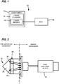
- FIG. 1 is a block diagram view of a system 10 including a component 12 for which determining the presence or absence of liquid may be desirable.
- the component 12 may include a liquid chamber 14, and the system 10 may further include a liquid sensor 16 and an electronic control unit (ECU) 18.
- ECU electronice control unit
- the component 12 may be any component in any field that includes or may be exposed to liquid in its operation.
- the component 12 may be or may be included in a mechanical, electrical, hydraulic, pneumatic, or other known actuator or actuation system.
- the component 12 may include a liquid chamber 14 configured to store or receive a liquid.
- the liquid may be, for example only, of a type necessary for the functionality of the component 12 (e.g., hydraulic fluid, liquid for lubrication, fuel, etc.), liquid incidental to the environment of the component 12, and/or liquid that is detrimental to the function of the component 12.
- the component 12 could be, for example, a gearbox that houses gears and high temperature lubricating oil.
- the gearbox could be a high performance type gearbox in an aerospace application, such as the gearbox of a jet engine.
- the temperature of the oil in the gearbox could be between 150 to 200 degrees Celsius. It should be appreciated that many alternative applications are possible.
- the liquid sensor 16 may be coupled with the component 12.
- the liquid sensor 16 may be disposed within the liquid chamber 14 of the component 12.
- the liquid sensor 16 may be an electro-optic sensor according to the present disclosure, such as that described in conjunction with FIGS. 2 and 3 . It should be appreciated that alternative embodiments are possible.
- the ECU 18 may be electrically coupled to the liquid sensor 16 and may be configured to drive the liquid sensor 16, receive feedback from the liquid sensor 16, assess whether liquid is present or absent in the liquid chamber 14, and/or assess the operational state of the liquid sensor 16.
- the ECU 18 may comprise, in embodiments, one or more of a processor, a non-volatile computer-readable memory, an application-specific integrated circuit (ASIC), field-programmable gate array (FPGA), and/or other known processing or memory devices.
- the ECU 18 may be or may comprise a dedicated processing resource for the liquid sensor 16, or may be or may comprise processing resources for numerous sensors, components, and/or systems.
- the ECU 18 may be electrically coupled to the liquid sensor 16 through known wired and/or wireless connections.
- FIG. 2 illustrates a multicomponent system wherein the ECU 18 (also referenced herein as Sensor Signal Conditioning Circuitry) is connected to the liquid sensor 16 via an electrical cable and electrical connector interface.
- the ECU 18 also referenced herein as Sensor Signal Conditioning Circuitry
- the hardware components including the light emitter, sensor, and temperature sensors are remote from the signal conditioning unit.
- FIG. 3 illustrates an alternative embodiment wherein the ECU/Sensor Signal Conditioning Circuitry 18 is integrated with the hardware components of the liquid sensor 16.
- FIG. 3 illustrates an embodiment wherein the ECU/Sensor Signal Conditioning Circuitry 18 is directly mounted to the sensor housing.
- FIG. 4 depicts an example physical housing of the integrated sensor of FIG. 3 .
- the sensor can be mounted via a single aperture into a tank and provide both fluid presence sensing and temperature sensing. It should be appreciated that alternative embodiments are possible.
- the ECU 18 can be configured to ascertain the temperature at the liquid sensor 16.
- the liquid sensor 16 may include a light source 20, a light detector 22, a prism 24, and a reflective optical member (which may also be referred to as an optical shield), which may be generally disposed within a housing 28.
- Reflective optical members are shown and described in further detail in U.S. Patent No. 10,222,251 to Kopansky et al. , which is incorporated by reference in its entirety.
- the light source 20 may be configured to emit light of a chosen frequency and power (or powers) appropriate for a given application (i.e., appropriate for the characteristics of the other elements of the sensor, such as shape, orientation, materials, reflectivity, etc., and/or according to characteristics of the liquid to be detected, such as density, scattering properties, etc.).
- a light frequency should be understood to include either/or both of a specific frequency of light and a frequency band.
- the light source 20 may be configured to emit light in the infrared portion and/or the near-infrared portion of the electromagnetic spectrum.
- the light source 20 may be or may include one or more of a light-emitting diode (LED), a laser, or other known light source, in an embodiment.
- LED light-emitting diode
- the light detector 22 may be configured, in an embodiment, to detect light of one or more frequencies of light, including at least the frequency of light emitted by the light source 20.
- the light detector 22 is a LED.
- the LED is not used to generate light but rather it is used in reverse to detect light.
- the light detecting LED is configured to generate a voltage or current when it detects light (e.g., when light is shined on the detecting LED). Whether a voltage or current is generated depends on the configuration of the diode arrangement within the system.
- the LED diode is an 850 nanometer peak emission Gallium-Aluminum-Arsenide (GaAIAs) type device. It should be appreciated that many alternatives are possible.
- the LED light emitter and/or LED light detector can alternatively have GaAS or GalnAs construction.
- the combination of the paired LED emitter and detector provides a liquid sensor that performs well in high temperature applications.
- the LED emitter can be configured to measure temperature as well.
- the LED light detector and the LED light emitter can be two of the same component. Using the same model LED for both the emitter and detector ensures that they are paired. It should be appreciated that the LED can be of different models and brands as well. As discussed above, the LED light detector is paired to the light emitting LED so long as the LED light detector can detect light of the frequency or wavelength that is emitted by the light emitting LED. To decrease susceptibility to ambient light noise, it can be desirable to further match the LED so that the nominal operable wavelength substantially overlaps. For example, in some embodiments, it can be desirable that the emitting LED only emits light in the range that the detecting LED can detect light. This decreases the likelihood that light from another source creates a false reading on the light detecting LED and increases the system's light immunity.
- the prism 24 may be a member, article, or device comprising one or more components configured in size, shape, and materials to reflect a light signal from the light source 20 to the light detector 22 in certain conditions, and to pass light from the light source 20 through the prism 24 in certain conditions.
- the prism 24 may be configured to reflect light from the light source 20 to the light detector 22 when liquid is not present around the prism 24, and to pass light from the light source 20 through the prism 24 when liquid is present around the prism 24.
- the prism 24 may comprise borosilicate glass, fused silica (quartz), one or more polymers, etc., that is optically-transmissive at least to light of the frequency emitted by the light source 20.
- the prism 24 may be optically-transmissive to light in the infrared and/or near-infrared portions of the electromagnetic spectrum, for example only.
- the IR emitter and temperature sensor diode are operably connected to a constant current source.
- the constant current source supplies current to the IR emitter for level sensing and/or temperature sensing functions.
- the temperature constant current source supplies a small current and offset current sufficient to mitigate component and environmental effects such as diode self-heating. This current could be, for example, within 0.1 to 1 mA range depending on the diode used and application temperature range.
- the level sensing excitation current source could be, for example, within 1 to 10 mA depending on the particular diode and application.
- the IR emitter and temperature sensor diode are operably connected to temperature signal conditioning circuitry.
- the temperature signal conditioning circuit converts the signal from the temperature diode to a °C/V signal mapped to the range of the temperature processing circuit and corrects for environmental offsets. For example, the temperature from -65 to 175°C could be mapped to 0 to 5V range for processing.
- the temperature signal conditioning circuitry is operably connected to temperature processing circuitry.
- the temperature processing circuit converts the signal from the conditioning circuit to the temperature output interface.
- the processing circuit could provide signal sampling and buffering for a digital serial output.
- the IR detector diode e.g., LED detector
- the signal conditioning circuit converts the raw signal from the IR detector to a format suitable for the signal processing circuit. For example, this circuit could amplify and filter the raw signal for further signal processing.
- the signal conditioning circuit is operably connected to signal processing circuitry.
- the signal processing circuitry converts the signal from the signal conditioning circuitry to a discrete liquid level output interface. For example, sampling and buffering the signal for a digital serial output or triggering a digital on/off signal.
- the system includes built-in test circuitry.
- the built-in test circuitry includes self-test capabilities to test level and temperature sensing functions.
Landscapes
- Physics & Mathematics (AREA)
- General Physics & Mathematics (AREA)
- Electromagnetism (AREA)
- Thermal Sciences (AREA)
- Fluid Mechanics (AREA)
- Investigating Or Analysing Materials By Optical Means (AREA)
- Measuring Temperature Or Quantity Of Heat (AREA)
Abstract
Description
- This application claims the benefit of
U.S. Patent Application Serial No. 62/968,653, filed on January 31, 2020 - The present disclosure relates to electro-optic sensors that can detect the presence or absence of fluid.
- Sensors for detecting the presence or absence of fluid and/or temperature have numerous applications. One known sensor type for detecting the presence or absence of fluid is an electro-optic liquid sensor. Electro-optic liquid sensors are described in
U.S. Patent No. 10,222,251 to Kopansky et al. - The present disclosure provides an electro-optic sensor that performs well in a wide range of temperatures. The fluid sensors of the present disclosure can be used in high temperature applications. In some embodiments, the sensor can detect the presence or absence of fluid as well as measure temperature.
- The following drawings are illustrative of particular embodiments of the present disclosure and therefore do not limit the scope of the present disclosure. The drawings are not to scale and are intended for use in conjunction with the explanations in the following detailed description. Embodiments of the present disclosure will hereinafter be described in conjunction with the appended drawings, wherein like numerals denote like elements.
-
FIG. 1 is a block diagram of an exemplary embodiment of a system including a component for which determining the presence or absence of fluid and/or temperature may be desirable; -
FIG. 2 is a cross-sectional view of an embodiment of the sensor of the present disclosure; -
FIG. 3 is a cross-sectional view of an alternative embodiment of the sensor ofFIG. 2 ; -
FIG. 4 is a side elevation view of a sensor according the present disclosure; and -
FIG. 5 is a block diagram of an embodiment of the system of the present disclosure. - Corresponding reference characters indicate corresponding parts throughout the several views. The exemplifications set out herein illustrate embodiments of the invention, and such exemplifications are not to be construed as limiting the scope of the invention in any manner.
- Reference will now be made in detail to embodiments of the present disclosure, examples of which are described herein and illustrated in the accompanying drawings. While the invention will be described in conjunction with embodiments, it will be understood that they are not intended to limit the invention to these embodiments. On the contrary, the invention is intended to cover alternatives, modifications and equivalents, which may be included within the spirit and scope of the invention as defined by the appended claims.
- Referring to the figures, in which like reference numerals refer to the same or similar features in the various views,
FIG. 1 is a block diagram view of asystem 10 including acomponent 12 for which determining the presence or absence of liquid may be desirable. Thecomponent 12 may include aliquid chamber 14, and thesystem 10 may further include aliquid sensor 16 and an electronic control unit (ECU) 18. - The
component 12 may be any component in any field that includes or may be exposed to liquid in its operation. For example, thecomponent 12 may be or may be included in a mechanical, electrical, hydraulic, pneumatic, or other known actuator or actuation system. Thecomponent 12 may include aliquid chamber 14 configured to store or receive a liquid. The liquid may be, for example only, of a type necessary for the functionality of the component 12 (e.g., hydraulic fluid, liquid for lubrication, fuel, etc.), liquid incidental to the environment of thecomponent 12, and/or liquid that is detrimental to the function of thecomponent 12. - In one embodiment, the
component 12 could be, for example, a gearbox that houses gears and high temperature lubricating oil. The gearbox could be a high performance type gearbox in an aerospace application, such as the gearbox of a jet engine. The temperature of the oil in the gearbox could be between 150 to 200 degrees Celsius. It should be appreciated that many alternative applications are possible. - The
liquid sensor 16 may be coupled with thecomponent 12. For example, theliquid sensor 16 may be disposed within theliquid chamber 14 of thecomponent 12. Theliquid sensor 16 may be an electro-optic sensor according to the present disclosure, such as that described in conjunction withFIGS. 2 and3 . It should be appreciated that alternative embodiments are possible. - The
ECU 18 may be electrically coupled to theliquid sensor 16 and may be configured to drive theliquid sensor 16, receive feedback from theliquid sensor 16, assess whether liquid is present or absent in theliquid chamber 14, and/or assess the operational state of theliquid sensor 16. The ECU 18 may comprise, in embodiments, one or more of a processor, a non-volatile computer-readable memory, an application-specific integrated circuit (ASIC), field-programmable gate array (FPGA), and/or other known processing or memory devices. The ECU 18 may be or may comprise a dedicated processing resource for theliquid sensor 16, or may be or may comprise processing resources for numerous sensors, components, and/or systems. TheECU 18 may be electrically coupled to theliquid sensor 16 through known wired and/or wireless connections. -
FIG. 2 illustrates a multicomponent system wherein the ECU 18 (also referenced herein as Sensor Signal Conditioning Circuitry) is connected to theliquid sensor 16 via an electrical cable and electrical connector interface. In the depicted embodiment, some of the hardware components including the light emitter, sensor, and temperature sensors are remote from the signal conditioning unit. -
FIG. 3 illustrates an alternative embodiment wherein the ECU/Sensor Signal Conditioning Circuitry 18 is integrated with the hardware components of theliquid sensor 16.FIG. 3 illustrates an embodiment wherein the ECU/Sensor Signal Conditioning Circuitry 18 is directly mounted to the sensor housing. -
FIG. 4 depicts an example physical housing of the integrated sensor ofFIG. 3 . In the depicted embodiment, the sensor can be mounted via a single aperture into a tank and provide both fluid presence sensing and temperature sensing. It should be appreciated that alternative embodiments are possible. - In addition to assessing the data from the
liquid sensor 16 to determine whether liquid is present or absent at theliquid sensor 16, theECU 18 can be configured to ascertain the temperature at theliquid sensor 16. - The
liquid sensor 16 may include alight source 20, alight detector 22, aprism 24, and a reflective optical member (which may also be referred to as an optical shield), which may be generally disposed within ahousing 28. Reflective optical members are shown and described in further detail inU.S. Patent No. 10,222,251 to Kopansky et al. - The
light source 20 may be configured to emit light of a chosen frequency and power (or powers) appropriate for a given application (i.e., appropriate for the characteristics of the other elements of the sensor, such as shape, orientation, materials, reflectivity, etc., and/or according to characteristics of the liquid to be detected, such as density, scattering properties, etc.). As used herein, a light frequency should be understood to include either/or both of a specific frequency of light and a frequency band. In an embodiment, thelight source 20 may be configured to emit light in the infrared portion and/or the near-infrared portion of the electromagnetic spectrum. Thelight source 20 may be or may include one or more of a light-emitting diode (LED), a laser, or other known light source, in an embodiment. - The
light detector 22 may be configured, in an embodiment, to detect light of one or more frequencies of light, including at least the frequency of light emitted by thelight source 20. In the depicted embodiment, thelight detector 22 is a LED. The LED is not used to generate light but rather it is used in reverse to detect light. The light detecting LED is configured to generate a voltage or current when it detects light (e.g., when light is shined on the detecting LED). Whether a voltage or current is generated depends on the configuration of the diode arrangement within the system. In one embodiment, the LED diode is an 850 nanometer peak emission Gallium-Aluminum-Arsenide (GaAIAs) type device. It should be appreciated that many alternatives are possible. For example, the LED light emitter and/or LED light detector can alternatively have GaAS or GalnAs construction. - The combination of the paired LED emitter and detector provides a liquid sensor that performs well in high temperature applications. In addition, as discussed above, the LED emitter can be configured to measure temperature as well.
- In the depicted embodiment, the LED light detector and the LED light emitter can be two of the same component. Using the same model LED for both the emitter and detector ensures that they are paired. It should be appreciated that the LED can be of different models and brands as well. As discussed above, the LED light detector is paired to the light emitting LED so long as the LED light detector can detect light of the frequency or wavelength that is emitted by the light emitting LED. To decrease susceptibility to ambient light noise, it can be desirable to further match the LED so that the nominal operable wavelength substantially overlaps. For example, in some embodiments, it can be desirable that the emitting LED only emits light in the range that the detecting LED can detect light. This decreases the likelihood that light from another source creates a false reading on the light detecting LED and increases the system's light immunity.
- The
prism 24 may be a member, article, or device comprising one or more components configured in size, shape, and materials to reflect a light signal from thelight source 20 to thelight detector 22 in certain conditions, and to pass light from thelight source 20 through theprism 24 in certain conditions. For example only, theprism 24 may be configured to reflect light from thelight source 20 to thelight detector 22 when liquid is not present around theprism 24, and to pass light from thelight source 20 through theprism 24 when liquid is present around theprism 24. In an embodiment, for example only, theprism 24 may comprise borosilicate glass, fused silica (quartz), one or more polymers, etc., that is optically-transmissive at least to light of the frequency emitted by thelight source 20. Thus, in an embodiment, theprism 24 may be optically-transmissive to light in the infrared and/or near-infrared portions of the electromagnetic spectrum, for example only. - Referring to
FIG. 5 , a block diagram of an embodiment of the system of the present disclosure is shown. In the depicted embodiment, the IR emitter and temperature sensor diode (e.g., LED emitter) are operably connected to a constant current source. In the depicted embodiment, the constant current source supplies current to the IR emitter for level sensing and/or temperature sensing functions. The temperature constant current source supplies a small current and offset current sufficient to mitigate component and environmental effects such as diode self-heating. This current could be, for example, within 0.1 to 1 mA range depending on the diode used and application temperature range. The level sensing excitation current source could be, for example, within 1 to 10 mA depending on the particular diode and application. - In the depicted embodiment, the IR emitter and temperature sensor diode (e.g., LED emitter) are operably connected to temperature signal conditioning circuitry. In the depicted embodiment, the temperature signal conditioning circuit converts the signal from the temperature diode to a °C/V signal mapped to the range of the temperature processing circuit and corrects for environmental offsets. For example, the temperature from -65 to 175°C could be mapped to 0 to 5V range for processing.
- In the depicted embodiment, the temperature signal conditioning circuitry is operably connected to temperature processing circuitry. In the depicted embodiment, the temperature processing circuit converts the signal from the conditioning circuit to the temperature output interface. For example, the processing circuit could provide signal sampling and buffering for a digital serial output.
- In the depicted embodiment, the IR detector diode (e.g., LED detector) is operably connected to signal conditioning circuitry. In the depicted embodiment, the signal conditioning circuit converts the raw signal from the IR detector to a format suitable for the signal processing circuit. For example, this circuit could amplify and filter the raw signal for further signal processing.
- In the depicted embodiment, the signal conditioning circuit is operably connected to signal processing circuitry. In the depicted embodiment, the signal processing circuitry converts the signal from the signal conditioning circuitry to a discrete liquid level output interface. For example, sampling and buffering the signal for a digital serial output or triggering a digital on/off signal.
- In the depicted embodiment, the system includes built-in test circuitry. In the depicted embodiment, the built-in test circuitry includes self-test capabilities to test level and temperature sensing functions.
- The various embodiments described above are provided by way of illustration only and should not be construed to limit the claims attached hereto. Those skilled in the art will readily recognize various modifications and changes that may be made without following the example embodiments and applications illustrated and described herein, and without departing from the true spirit and scope of the following claims.
Claims (19)
- An electro-optic liquid sensor comprising:an LED light emitter;an LED light detector; anda prism configured to reflect light emitted from the LED light emitter to the LED light detector.
- The sensor of claim 1, wherein the LED light emitter is configured to generate light of a first range of wavelengths, wherein the LED light detector is configured to generate voltage when the light of the first range of wavelengths is shined on the LED light detector.
- The sensor of claim 1, wherein the LED light emitter is configured to generate light of a first range of wavelengths, wherein the LED light detector is configured to generate current when the light of the first range of wavelengths is shined on the LED light detector.
- The sensor of claim 1, wherein the LED light emitter and the LED light detector are LED that share substantially the same overlapping operating wavelength ranges.
- The sensor of claim 1, further comprising a housing including a first end and a second end, wherein the LED light emitter is secured in the housing and the LED light detector is secured in the housing, wherein the prism is connected to the first end of the housing, wherein the housing is sealed and configured to be at least partially immersed into a tank containing liquid.
- The sensor of claim 5, further comprising a thermally conductive light blocking chassis located in a first end portion of the housing, wherein the LED light emitter and the LED light detector are secured in the thermally conductive light blocking chassis.
- The sensor of claim 5, wherein the housing comprises a seal flange at the second end of the housing, the seal flange configured to seal an opening in a tank wall into which the first end of the housing extends.
- The sensor of claim 5, wherein the second end of the housing is configured to mate with an electrical connector
- The sensor of claim 5, wherein the tank is a gearbox and the liquid is oil.
- The sensor of claim 1, wherein the LED light emitter emits infrared or near-infrared light, and wherein the LED light detector detects infrared or near-infrared light.
- The sensor of claim 1, wherein the LED light emitter emits visible light, and wherein the LED light detector detects visible light.
- The sensor of claim 1, wherein the LED light emitter emits ultraviolet light, and wherein the LED light detector detects ultraviolet light.
- The sensor of claim 1, further comprising a reflective optical member, wherein the reflective optical member is arranged to reflect light emitted by the LED light emitter to the LED light detector and the LED light emitter is configured to provide light at a plurality of intensity for assessing an operational state of the sensor.
- The sensor of claim 1, wherein at least one of the LED light emitter or LED light detector is also a temperature sensor, wherein a signal conditioning unit is configured to determine the temperature of the liquid in the tank.
- The sensor of claim 1, wherein the LED light emitter and the LED light detector are 850 nanometer peak emission Gallium-Aluminum-Arsenide LED diodes.
- The sensor of claim 5, wherein the temperature of the liquid is at least 150 degrees Celsius.
- The sensor of claim 1, wherein the LED light emitter and the LED light detector are paired in terms of wavelength specifications.
- The sensor of claim 1, wherein the LED light emitter and the LED light detector have the same hardware construction.
- An electro-optic liquid sensor system comprising:a sensor including:a sealed housing including a first end and a second end;an LED light emitter secured in the housing;an LED light detector secured in the housing; anda prism connected to the first end of the housing configured to reflectlight emitted from the LED light emitter to the LED light detector;an electrical connector connected to the second end of the housing;an electrical cable including a first end connected to the electrical connector; anda signal conditioning unit connected to a second end of the electrical cable.
Applications Claiming Priority (1)
| Application Number | Priority Date | Filing Date | Title |
|---|---|---|---|
| US202062968653P | 2020-01-31 | 2020-01-31 |
Publications (2)
| Publication Number | Publication Date |
|---|---|
| EP3859288A1 true EP3859288A1 (en) | 2021-08-04 |
| EP3859288B1 EP3859288B1 (en) | 2025-04-23 |
Family
ID=74418170
Family Applications (1)
| Application Number | Title | Priority Date | Filing Date |
|---|---|---|---|
| EP21154154.5A Active EP3859288B1 (en) | 2020-01-31 | 2021-01-28 | Electro-optic sensor |
Country Status (2)
| Country | Link |
|---|---|
| US (1) | US11781896B2 (en) |
| EP (1) | EP3859288B1 (en) |
Families Citing this family (2)
| Publication number | Priority date | Publication date | Assignee | Title |
|---|---|---|---|---|
| US20230117200A1 (en) | 2021-10-14 | 2023-04-20 | Eaton Intelligent Power Limited | In-line debris separtor for liquid |
| US20230236058A1 (en) * | 2022-01-21 | 2023-07-27 | Eaton Intelligent Power Limited | Methods and systems for testing electro optic sensors |
Citations (8)
| Publication number | Priority date | Publication date | Assignee | Title |
|---|---|---|---|---|
| DE3519342A1 (en) * | 1985-05-30 | 1986-12-04 | Hella KG Hueck & Co, 4780 Lippstadt | Device for measuring and monitoring the filling level of a liquid container |
| US4946242A (en) * | 1987-08-28 | 1990-08-07 | Hitachi, Ltd. | Optical part including integral combination of optical fiber and light emitting or receiving element and method of manufacturing the same |
| US5029471A (en) * | 1990-10-23 | 1991-07-09 | Watkins Johnson Company | Liquid level sensor assembly |
| US5279157A (en) * | 1992-08-03 | 1994-01-18 | Casco Products Corporation | Liquid level monitor |
| US5765994A (en) * | 1995-07-14 | 1998-06-16 | Barbier; William J. | Low oil detector with automatic reset |
| US20120140233A1 (en) * | 2010-12-07 | 2012-06-07 | Rockwell Thomas L | Apparatus and method for detecting the presence of water on a remote surface |
| US8264171B1 (en) * | 2009-05-22 | 2012-09-11 | Ixys Corporation | In-situ LED junction temperature monitoring using LED as temperature sensor |
| US10222251B2 (en) | 2013-09-10 | 2019-03-05 | Eaton Intelligent Power Limited | Electro-optic liquid sensor enabling in-liquid testing having a light source providing a plurality of intensities for assessing an operational state of the sensor |
Family Cites Families (8)
| Publication number | Priority date | Publication date | Assignee | Title |
|---|---|---|---|---|
| CA1087269A (en) * | 1976-09-03 | 1980-10-07 | William F. Jacobsen | Frequency sensitive level detecting apparatus |
| DE4129719A1 (en) * | 1991-09-06 | 1992-03-05 | Gistl Egmont | Simultaneous oil temp. and level measuring appts. - uses single phototransistor and light emitting diode with functional changeover by optical coupler for simultaneous display |
| US6661504B2 (en) * | 1997-03-05 | 2003-12-09 | John Rakucewicz | Failure detecting optoelectronic sensor |
| US6681585B1 (en) | 2003-01-23 | 2004-01-27 | Whirlpool Corporation | Liquid dispenser with self-filling container |
| US7259383B2 (en) * | 2004-04-22 | 2007-08-21 | Opti Sensor Systems, Llc | Optical transducer for detecting liquid level |
| US8028942B2 (en) * | 2008-08-01 | 2011-10-04 | Fellowes, Inc. | Bin full detection with light intensity sensing |
| US9164001B2 (en) * | 2013-06-28 | 2015-10-20 | Bridgelux, Inc. | Using an LED die to measure temperature inside silicone that encapsulates an LED array |
| ES2949695T3 (en) | 2016-06-08 | 2023-10-02 | Eaton Intelligent Power Ltd | Fluid Sensor Assembly |
-
2021
- 2021-01-27 US US17/160,240 patent/US11781896B2/en active Active
- 2021-01-28 EP EP21154154.5A patent/EP3859288B1/en active Active
Patent Citations (8)
| Publication number | Priority date | Publication date | Assignee | Title |
|---|---|---|---|---|
| DE3519342A1 (en) * | 1985-05-30 | 1986-12-04 | Hella KG Hueck & Co, 4780 Lippstadt | Device for measuring and monitoring the filling level of a liquid container |
| US4946242A (en) * | 1987-08-28 | 1990-08-07 | Hitachi, Ltd. | Optical part including integral combination of optical fiber and light emitting or receiving element and method of manufacturing the same |
| US5029471A (en) * | 1990-10-23 | 1991-07-09 | Watkins Johnson Company | Liquid level sensor assembly |
| US5279157A (en) * | 1992-08-03 | 1994-01-18 | Casco Products Corporation | Liquid level monitor |
| US5765994A (en) * | 1995-07-14 | 1998-06-16 | Barbier; William J. | Low oil detector with automatic reset |
| US8264171B1 (en) * | 2009-05-22 | 2012-09-11 | Ixys Corporation | In-situ LED junction temperature monitoring using LED as temperature sensor |
| US20120140233A1 (en) * | 2010-12-07 | 2012-06-07 | Rockwell Thomas L | Apparatus and method for detecting the presence of water on a remote surface |
| US10222251B2 (en) | 2013-09-10 | 2019-03-05 | Eaton Intelligent Power Limited | Electro-optic liquid sensor enabling in-liquid testing having a light source providing a plurality of intensities for assessing an operational state of the sensor |
Non-Patent Citations (1)
| Title |
|---|
| LAU K T ET AL: "A low-cost optical sensing device based on paired emitter-detector light emitting diodes", ANALYTICA CHIMICA ACTA, ELSEVIER, AMSTERDAM, NL, vol. 557, no. 1-2, 31 January 2006 (2006-01-31), pages 111 - 116, XP027912442, ISSN: 0003-2670, [retrieved on 20060131] * |
Also Published As
| Publication number | Publication date |
|---|---|
| EP3859288B1 (en) | 2025-04-23 |
| US11781896B2 (en) | 2023-10-10 |
| US20210239508A1 (en) | 2021-08-05 |
Similar Documents
| Publication | Publication Date | Title |
|---|---|---|
| KR101393943B1 (en) | Fiber optic temperature sensor | |
| US11781896B2 (en) | Electro-optic sensor | |
| JP6693759B2 (en) | Multifunctional fiber optic fuel sensor system with photonic membrane background | |
| US10627281B2 (en) | Electro-optic liquid sensor enabling in-liquid testing | |
| US8053728B2 (en) | Gas sensor with an especially explosion-proof housing | |
| US11680840B2 (en) | Method of operating an electro-optic liquid sensor to determine presence of liquid based on an amount of reflected light | |
| EP2694948B1 (en) | Analyzer instrument and methods for operating same | |
| US7196320B1 (en) | Fiber optic encoder for position sensing | |
| EP3370311A1 (en) | Method of determining operation conditions of a laser-based particle detector | |
| EP3760985B1 (en) | Electro-optic liquid sensor | |
| US10761017B2 (en) | Gas detection system, gas detection method and program | |
| US20140036257A1 (en) | Analyzer Instrument And Methods For Operating Same | |
| US8362436B1 (en) | Electro-optic fluid quantity measurement system | |
| EP3318849A1 (en) | Electro-optic liquid sensor | |
| US6581461B1 (en) | Electro-optic sensor for levelmeter providing output signal with frequency modulated by surface level | |
| JP2008232707A (en) | Infrared touch switch | |
| JP4315280B2 (en) | Flame detector | |
| US7589329B1 (en) | Systems and methods for remote optical sensing | |
| CN120457333A (en) | Light emitting diode and turbidity sensor having the same | |
| CN223769557U (en) | Integrated pressure and temperature sensor | |
| JP2025137396A (en) | Optical concentration measuring device and signal processing unit | |
| JP4881643B2 (en) | Gas detector adapter and gas detector calibration method | |
| CN120609773A (en) | Optical concentration measuring device and signal processing unit | |
| JP2001194209A (en) | Level gage | |
| CZ280008B6 (en) | Temperature sensor |
Legal Events
| Date | Code | Title | Description |
|---|---|---|---|
| PUAI | Public reference made under article 153(3) epc to a published international application that has entered the european phase |
Free format text: ORIGINAL CODE: 0009012 |
|
| STAA | Information on the status of an ep patent application or granted ep patent |
Free format text: STATUS: REQUEST FOR EXAMINATION WAS MADE |
|
| 17P | Request for examination filed |
Effective date: 20210128 |
|
| AK | Designated contracting states |
Kind code of ref document: A1 Designated state(s): AL AT BE BG CH CY CZ DE DK EE ES FI FR GB GR HR HU IE IS IT LI LT LU LV MC MK MT NL NO PL PT RO RS SE SI SK SM TR |
|
| STAA | Information on the status of an ep patent application or granted ep patent |
Free format text: STATUS: EXAMINATION IS IN PROGRESS |
|
| 17Q | First examination report despatched |
Effective date: 20230417 |
|
| P01 | Opt-out of the competence of the unified patent court (upc) registered |
Effective date: 20230521 |
|
| GRAP | Despatch of communication of intention to grant a patent |
Free format text: ORIGINAL CODE: EPIDOSNIGR1 |
|
| STAA | Information on the status of an ep patent application or granted ep patent |
Free format text: STATUS: GRANT OF PATENT IS INTENDED |
|
| GRAJ | Information related to disapproval of communication of intention to grant by the applicant or resumption of examination proceedings by the epo deleted |
Free format text: ORIGINAL CODE: EPIDOSDIGR1 |
|
| STAA | Information on the status of an ep patent application or granted ep patent |
Free format text: STATUS: EXAMINATION IS IN PROGRESS |
|
| RIC1 | Information provided on ipc code assigned before grant |
Ipc: G01K 13/02 20210101ALN20241004BHEP Ipc: G01F 23/292 20060101AFI20241004BHEP |
|
| GRAP | Despatch of communication of intention to grant a patent |
Free format text: ORIGINAL CODE: EPIDOSNIGR1 |
|
| STAA | Information on the status of an ep patent application or granted ep patent |
Free format text: STATUS: GRANT OF PATENT IS INTENDED |
|
| INTG | Intention to grant announced |
Effective date: 20241016 |
|
| INTC | Intention to grant announced (deleted) | ||
| INTG | Intention to grant announced |
Effective date: 20241119 |
|
| RIC1 | Information provided on ipc code assigned before grant |
Ipc: G01K 13/02 20210101ALN20241108BHEP Ipc: G01K 7/01 20060101ALI20241108BHEP Ipc: G01F 23/292 20060101AFI20241108BHEP |
|
| GRAS | Grant fee paid |
Free format text: ORIGINAL CODE: EPIDOSNIGR3 |
|
| GRAA | (expected) grant |
Free format text: ORIGINAL CODE: 0009210 |
|
| STAA | Information on the status of an ep patent application or granted ep patent |
Free format text: STATUS: THE PATENT HAS BEEN GRANTED |
|
| AK | Designated contracting states |
Kind code of ref document: B1 Designated state(s): AL AT BE BG CH CY CZ DE DK EE ES FI FR GB GR HR HU IE IS IT LI LT LU LV MC MK MT NL NO PL PT RO RS SE SI SK SM TR |
|
| REG | Reference to a national code |
Ref country code: GB Ref legal event code: FG4D |
|
| REG | Reference to a national code |
Ref country code: CH Ref legal event code: EP |
|
| REG | Reference to a national code |
Ref country code: DE Ref legal event code: R096 Ref document number: 602021029438 Country of ref document: DE |
|
| REG | Reference to a national code |
Ref country code: IE Ref legal event code: FG4D |
|
| REG | Reference to a national code |
Ref country code: NL Ref legal event code: MP Effective date: 20250423 |
|
| PG25 | Lapsed in a contracting state [announced via postgrant information from national office to epo] |
Ref country code: NL Free format text: LAPSE BECAUSE OF FAILURE TO SUBMIT A TRANSLATION OF THE DESCRIPTION OR TO PAY THE FEE WITHIN THE PRESCRIBED TIME-LIMIT Effective date: 20250423 |
|
| REG | Reference to a national code |
Ref country code: AT Ref legal event code: MK05 Ref document number: 1788144 Country of ref document: AT Kind code of ref document: T Effective date: 20250423 |
|
| PG25 | Lapsed in a contracting state [announced via postgrant information from national office to epo] |
Ref country code: PT Free format text: LAPSE BECAUSE OF FAILURE TO SUBMIT A TRANSLATION OF THE DESCRIPTION OR TO PAY THE FEE WITHIN THE PRESCRIBED TIME-LIMIT Effective date: 20250825 Ref country code: FI Free format text: LAPSE BECAUSE OF FAILURE TO SUBMIT A TRANSLATION OF THE DESCRIPTION OR TO PAY THE FEE WITHIN THE PRESCRIBED TIME-LIMIT Effective date: 20250423 Ref country code: ES Free format text: LAPSE BECAUSE OF FAILURE TO SUBMIT A TRANSLATION OF THE DESCRIPTION OR TO PAY THE FEE WITHIN THE PRESCRIBED TIME-LIMIT Effective date: 20250423 |
|
| REG | Reference to a national code |
Ref country code: LT Ref legal event code: MG9D |
|
| PG25 | Lapsed in a contracting state [announced via postgrant information from national office to epo] |
Ref country code: NO Free format text: LAPSE BECAUSE OF FAILURE TO SUBMIT A TRANSLATION OF THE DESCRIPTION OR TO PAY THE FEE WITHIN THE PRESCRIBED TIME-LIMIT Effective date: 20250723 Ref country code: GR Free format text: LAPSE BECAUSE OF FAILURE TO SUBMIT A TRANSLATION OF THE DESCRIPTION OR TO PAY THE FEE WITHIN THE PRESCRIBED TIME-LIMIT Effective date: 20250724 |
|
| PG25 | Lapsed in a contracting state [announced via postgrant information from national office to epo] |
Ref country code: PL Free format text: LAPSE BECAUSE OF FAILURE TO SUBMIT A TRANSLATION OF THE DESCRIPTION OR TO PAY THE FEE WITHIN THE PRESCRIBED TIME-LIMIT Effective date: 20250423 |
|
| PG25 | Lapsed in a contracting state [announced via postgrant information from national office to epo] |
Ref country code: BG Free format text: LAPSE BECAUSE OF FAILURE TO SUBMIT A TRANSLATION OF THE DESCRIPTION OR TO PAY THE FEE WITHIN THE PRESCRIBED TIME-LIMIT Effective date: 20250423 |
|
| PG25 | Lapsed in a contracting state [announced via postgrant information from national office to epo] |
Ref country code: HR Free format text: LAPSE BECAUSE OF FAILURE TO SUBMIT A TRANSLATION OF THE DESCRIPTION OR TO PAY THE FEE WITHIN THE PRESCRIBED TIME-LIMIT Effective date: 20250423 |
|
| PG25 | Lapsed in a contracting state [announced via postgrant information from national office to epo] |
Ref country code: AT Free format text: LAPSE BECAUSE OF FAILURE TO SUBMIT A TRANSLATION OF THE DESCRIPTION OR TO PAY THE FEE WITHIN THE PRESCRIBED TIME-LIMIT Effective date: 20250423 |
|
| PG25 | Lapsed in a contracting state [announced via postgrant information from national office to epo] |
Ref country code: RS Free format text: LAPSE BECAUSE OF FAILURE TO SUBMIT A TRANSLATION OF THE DESCRIPTION OR TO PAY THE FEE WITHIN THE PRESCRIBED TIME-LIMIT Effective date: 20250723 |
|
| PG25 | Lapsed in a contracting state [announced via postgrant information from national office to epo] |
Ref country code: IS Free format text: LAPSE BECAUSE OF FAILURE TO SUBMIT A TRANSLATION OF THE DESCRIPTION OR TO PAY THE FEE WITHIN THE PRESCRIBED TIME-LIMIT Effective date: 20250823 |
|
| PG25 | Lapsed in a contracting state [announced via postgrant information from national office to epo] |
Ref country code: LV Free format text: LAPSE BECAUSE OF FAILURE TO SUBMIT A TRANSLATION OF THE DESCRIPTION OR TO PAY THE FEE WITHIN THE PRESCRIBED TIME-LIMIT Effective date: 20250423 |
|
| PGFP | Annual fee paid to national office [announced via postgrant information from national office to epo] |
Ref country code: GB Payment date: 20251220 Year of fee payment: 6 |
|
| PG25 | Lapsed in a contracting state [announced via postgrant information from national office to epo] |
Ref country code: DK Free format text: LAPSE BECAUSE OF FAILURE TO SUBMIT A TRANSLATION OF THE DESCRIPTION OR TO PAY THE FEE WITHIN THE PRESCRIBED TIME-LIMIT Effective date: 20250423 Ref country code: SM Free format text: LAPSE BECAUSE OF FAILURE TO SUBMIT A TRANSLATION OF THE DESCRIPTION OR TO PAY THE FEE WITHIN THE PRESCRIBED TIME-LIMIT Effective date: 20250423 |
|
| PGFP | Annual fee paid to national office [announced via postgrant information from national office to epo] |
Ref country code: FR Payment date: 20251217 Year of fee payment: 6 |
|
| PG25 | Lapsed in a contracting state [announced via postgrant information from national office to epo] |
Ref country code: CZ Free format text: LAPSE BECAUSE OF FAILURE TO SUBMIT A TRANSLATION OF THE DESCRIPTION OR TO PAY THE FEE WITHIN THE PRESCRIBED TIME-LIMIT Effective date: 20250423 |
|
| PG25 | Lapsed in a contracting state [announced via postgrant information from national office to epo] |
Ref country code: EE Free format text: LAPSE BECAUSE OF FAILURE TO SUBMIT A TRANSLATION OF THE DESCRIPTION OR TO PAY THE FEE WITHIN THE PRESCRIBED TIME-LIMIT Effective date: 20250423 |
|
| REG | Reference to a national code |
Ref country code: DE Ref legal event code: R097 Ref document number: 602021029438 Country of ref document: DE |
|
| PG25 | Lapsed in a contracting state [announced via postgrant information from national office to epo] |
Ref country code: SK Free format text: LAPSE BECAUSE OF FAILURE TO SUBMIT A TRANSLATION OF THE DESCRIPTION OR TO PAY THE FEE WITHIN THE PRESCRIBED TIME-LIMIT Effective date: 20250423 Ref country code: RO Free format text: LAPSE BECAUSE OF FAILURE TO SUBMIT A TRANSLATION OF THE DESCRIPTION OR TO PAY THE FEE WITHIN THE PRESCRIBED TIME-LIMIT Effective date: 20250423 |
|
| PLBE | No opposition filed within time limit |
Free format text: ORIGINAL CODE: 0009261 |
|
| STAA | Information on the status of an ep patent application or granted ep patent |
Free format text: STATUS: NO OPPOSITION FILED WITHIN TIME LIMIT |
|
| REG | Reference to a national code |
Ref country code: CH Ref legal event code: L10 Free format text: ST27 STATUS EVENT CODE: U-0-0-L10-L00 (AS PROVIDED BY THE NATIONAL OFFICE) Effective date: 20260304 |
|
| 26N | No opposition filed |
Effective date: 20260126 |
|
| PGFP | Annual fee paid to national office [announced via postgrant information from national office to epo] |
Ref country code: DE Payment date: 20251217 Year of fee payment: 6 |
|
| PGFP | Annual fee paid to national office [announced via postgrant information from national office to epo] |
Ref country code: IT Payment date: 20260107 Year of fee payment: 6 |